JP5178617B2 - Light irradiation device and inspection device - Google Patents
Light irradiation device and inspection device Download PDFInfo
- Publication number
- JP5178617B2 JP5178617B2 JP2009106435A JP2009106435A JP5178617B2 JP 5178617 B2 JP5178617 B2 JP 5178617B2 JP 2009106435 A JP2009106435 A JP 2009106435A JP 2009106435 A JP2009106435 A JP 2009106435A JP 5178617 B2 JP5178617 B2 JP 5178617B2
- Authority
- JP
- Japan
- Prior art keywords
- light
- light guide
- groove
- reflected
- reflector
- Prior art date
- Legal status (The legal status is an assumption and is not a legal conclusion. Google has not performed a legal analysis and makes no representation as to the accuracy of the status listed.)
- Expired - Fee Related
Links
Images


Landscapes
- Liquid Crystal (AREA)
- Non-Portable Lighting Devices Or Systems Thereof (AREA)
- Planar Illumination Modules (AREA)
Description
本発明は、光照射装置および検査装置に関する。 The present invention relates to a light irradiation apparatus and an inspection apparatus.
従来、光照射装置としては、特開2004−249998号公報(特許文献1)に記載されているフロントライト方式の反射型液晶用照射装置がある。 Conventionally, as a light irradiation apparatus, there is a front light type reflection liquid crystal irradiation apparatus described in Japanese Patent Application Laid-Open No. 2004-249998 (Patent Document 1).
この反射型液晶用照射装置は、導光体に溝部を形成しておいて、導光体から漏れ光を発生させて、その漏れ光を液晶パネルに照射するようになっている。そして、上記液晶パネルからの反射光を導光板の上面(反射体と反対面)側に照射するようになっている。 In this reflection type liquid crystal irradiation device, a groove is formed in the light guide, leakage light is generated from the light guide, and the liquid crystal panel is irradiated with the leakage light. And the reflected light from the said liquid crystal panel is irradiated to the upper surface (opposite surface to a reflector) side of a light-guide plate.
この反射型液晶用照射装置は、導光体の上記溝部の溝形状を変化させることにより、導光板の漏れ光を均一化するようになっており、液晶パネルを照射する照度を均一化するようになっている。 In this reflection type liquid crystal irradiation device, the light leakage of the light guide plate is made uniform by changing the groove shape of the groove portion of the light guide, and the illuminance to irradiate the liquid crystal panel is made uniform. It has become.
また、従来、他の光照射装置としては、特表2006−511050号公報(特許文献2)に記載されている反射型液晶用照射装置がある。 Conventionally, as another light irradiation apparatus, there is a reflection type liquid crystal irradiation apparatus described in JP-T-2006-511050 (Patent Document 2).
この反射型液晶照射装置は、光源を、導光体の両側に配置し、さらに、導光体内部の溝の形状を中心対称に変化させて、照度を均一化するようになっている。 In this reflection type liquid crystal irradiation device, light sources are arranged on both sides of the light guide, and the shape of the grooves inside the light guide is changed symmetrically to make the illuminance uniform.
上述のように、上記従来の光照射装置では、導光体からの漏れ光を反射体である反射型液晶パネルで反射させ、導光体からの出射光のみで、照射する照度の均一性を確保している。上記従来の光照射装置では、設計段階では照度ムラを最小にする構造を実現することができるが、設計段階で照度ムラが最小であったとしても、試作時の作製誤差の影響で照度ムラが発生することが避けがたく、この照度ムラを、調整することができない。そして、その結果、作製時に発生した照度ムラをそのまま残した光照射装置しか実現できない。加えて、従来の装置では、反射率の可変を行うことができず、かつ、特定の部分だけを照射することができないから、溝部からの漏れ光の反射も考慮して、照度ムラの均一化の調整を行うことができない。 As described above, in the conventional light irradiation device, the leakage light from the light guide is reflected by the reflective liquid crystal panel, which is a reflector, and the uniformity of the illuminance to be irradiated is made only by the light emitted from the light guide. Secured. The conventional light irradiation device can realize a structure that minimizes the illuminance unevenness at the design stage, but even if the illuminance unevenness is minimum at the design stage, the illuminance unevenness is affected by the manufacturing error at the time of the prototype. It is unavoidable to occur, and this illuminance unevenness cannot be adjusted. As a result, only the light irradiation device that leaves the illuminance unevenness generated at the time of manufacture can be realized. In addition, with conventional devices, the reflectance cannot be varied, and only a specific part cannot be irradiated. Cannot be adjusted.
また、従来の均一化原理を採用した反射型液晶用の光照射装置を、太陽電池の検査装置用光照射装置として用いると、照度調整を精度良く行うことが困難な構成であるから、照度均一性の低下により評価性能が落ちることになる。 In addition, when a conventional light irradiation device for a reflective liquid crystal that uses the principle of uniformization is used as a light irradiation device for a solar cell inspection device, it is difficult to accurately adjust the illuminance. As a result, the evaluation performance deteriorates.
そこで、本発明の課題は、照度の均一化の調整ができる光照射装置を提供することにある。また、本発明の課題は、そのような光照射装置を備える検査装置を提供することにある。 Then, the subject of this invention is providing the light irradiation apparatus which can adjust the uniformity of illumination intensity. Moreover, the subject of this invention is providing an inspection apparatus provided with such a light irradiation apparatus.
上記課題を解決するため、この発明の光照射装置は、
光源と、
光が出射される光出射面と、この光出射面に対向すると共に、一方向に互いに間隔をおいて位置する複数の溝が形成された溝形成面とを有する導光体と、
上記光源からの光を上記導光体に案内する光学部材と、
上記導光体の上記溝形成面に対向する反射面を有する反射体と
を備え、
上記導光体の上記各溝は、上記一方向を法線とする平面に対して傾斜する傾斜面を有し、
上記光源からの光のうちの一部の光は、上記傾斜面で反射して上記反射面に到達すると共に、上記一部の光であって、上記反射面で反射した光の少なくとも一部は、上記導光体の上記光出射面に到達し、
上記反射体の上記反射面は、上記光源からの光の一部であって上記溝の上記傾斜面で反射する光が到達可能な第1部分と、この第1部分に対して間隔をおいて位置すると共に、上記傾斜面以外の面から反射された光が入射する第2部分とを有し、
上記第1部分の光の反射率は、上記第2部分の光の反射率と異なることを特徴としている。
In order to solve the above problems, the light irradiation device of the present invention is:
A light source;
A light guide having a light emitting surface from which light is emitted, and a groove forming surface formed with a plurality of grooves facing the light emitting surface and spaced apart from each other in one direction;
An optical member for guiding light from the light source to the light guide;
A reflector having a reflecting surface facing the groove forming surface of the light guide,
Each groove of the light guide has an inclined surface that is inclined with respect to a plane whose normal is the one direction,
A part of the light from the light source is reflected by the inclined surface and reaches the reflecting surface, and at least a part of the light reflected by the reflecting surface is the part of the light. Reaching the light exit surface of the light guide ,
The reflecting surface of the reflector is a part of the light from the light source and can be reached by light reflected by the inclined surface of the groove, and is spaced from the first part. And a second portion on which light reflected from a surface other than the inclined surface is incident,
Reflectance of light of the first portion is characterized Rukoto different from the reflectance of light of the second portion.
本発明によれば、導光体の上記各溝は、上記一方向を法線とする平面に対して傾斜する傾斜面を有し、かつ、導光体の上記光出射面に対向する反射面を有する反射体を備えるから、傾斜面の傾斜を適宜適切な傾斜にすることにより、上記光源からの光であって導光体の溝から反射面に向かう光の拡がり角度を制限できる。したがって、その反射面に向かう光の上記反射体での反射光で、上記導光体の上記光出射面での所定の範囲(または、光照射装置が照射する照射面の所定の範囲)における光の照度を調整することができる。 According to the present invention, each of the grooves of the light guide has an inclined surface that is inclined with respect to a plane whose normal is the one direction, and is a reflective surface that faces the light emitting surface of the light guide. Therefore, by appropriately setting the inclination of the inclined surface to an appropriate angle, the spread angle of the light from the light source toward the reflecting surface from the groove of the light guide can be limited. Therefore, the light traveling toward the reflecting surface is reflected by the reflector and is light in a predetermined range (or a predetermined range of the irradiation surface irradiated by the light irradiation device) on the light emitting surface of the light guide. The illuminance can be adjusted.
また、一実施形態では、
上記光学部材は、上記光源からの光であって上記導光体に案内される光が上記導光体の上記光出射面に入射する際の最大の入射角が、上記光出射面の全反射の臨界角よりも大きくなるように、上記光源からの光の進路を制限し、
上記溝の上記斜面が上記導光体の上記光出射面に対してなす角の角度および上記最大の入射角の角度で、上記光源からの光の一部であって上記溝の上記傾斜面と上記反射面で反射して上記光出射面に到達した光の照射範囲を制限することによって、上記光出射面から出射される光が上記光出射面の出射位置によらずより一様に近づくように照射する。
In one embodiment,
The optical member has a maximum incident angle when light from the light source and guided to the light guide is incident on the light exit surface of the light guide. Limiting the path of light from the light source to be greater than the critical angle of
The angle formed by the inclined surface of the groove with respect to the light exit surface of the light guide and the angle of the maximum incident angle is a part of light from the light source and the inclined surface of the groove By limiting the irradiation range of the light reflected by the reflecting surface and reaching the light emitting surface, the light emitted from the light emitting surface approaches more uniformly regardless of the emitting position of the light emitting surface. Irradiate.
上記実施形態によれば、上記溝の上記傾斜面で反射する調整光に基づく導光体の光出射面(光照射装置が照射する照射面)での照度の調整範囲を、更に局所化、細分化することができる。 According to the embodiment, the adjustment range of the illuminance on the light exit surface (irradiation surface irradiated by the light irradiation device) of the light guide based on the adjustment light reflected by the inclined surface of the groove is further localized and subdivided. Can be
また、本発明によれば、光源からの光であって反射体での反射光による調整の幅(自由度)を更に格段に拡げることができる。 Further , according to the present invention , the range of adjustment (degree of freedom) by light reflected from the light source and reflected by the reflector can be further expanded.
また、本発明の光照射装置は、
光源と、
光が出射される光出射面と、この光出射面に対向すると共に、一方向に互いに間隔をおいて位置する複数の溝が形成された溝形成面とを有する導光体と、
上記光源からの光を上記導光体に案内する光学部材と、
上記導光体の上記溝形成面に対向する反射面を有する反射体と
を備え、
上記導光体の上記各溝は、上記一方向を法線とする平面に対して傾斜する傾斜面を有し、
上記光源からの光のうちの一部の光は、上記傾斜面で反射して上記反射面に到達すると共に、上記一部の光であって、上記反射面で反射した光の少なくとも一部は、上記導光体の上記光出射面に到達し、
上記反射体の上記反射面は、上記光源からの光の一部であって上記溝の上記傾斜面で反射する光が到達可能な第1部分と、この第1部分に対して間隔をおいて位置すると共に、上記傾斜面以外の面から反射された光が入射する第2部分とを有し、
上記第1部分の反射率は、上記第1部分に入射する光の入射角に基づいて変動する角度依存性を有すると共に、上記第2部分の反射率は、上記第2部分に入射する光の入射角に基づいて変動する角度依存性を有し、
上記第1部分の反射率の角度依存性は、上記第2部分の反射率の角度依存性と異なることを特徴としている。
Moreover, the light irradiation device of the present invention comprises:
A light source;
A light guide having a light emitting surface from which light is emitted, and a groove forming surface formed with a plurality of grooves facing the light emitting surface and spaced apart from each other in one direction;
An optical member for guiding light from the light source to the light guide;
A reflector having a reflecting surface facing the groove forming surface of the light guide;
With
Each groove of the light guide has an inclined surface that is inclined with respect to a plane whose normal is the one direction,
A part of the light from the light source is reflected by the inclined surface and reaches the reflecting surface, and at least a part of the light reflected by the reflecting surface is the part of the light. Reaching the light exit surface of the light guide,
The reflecting surface of the reflector is a part of the light from the light source and can be reached by light reflected by the inclined surface of the groove, and is spaced from the first part. And a second portion on which light reflected from a surface other than the inclined surface is incident ,
The reflectance of the first part has an angle dependency that varies based on the incident angle of the light incident on the first part, and the reflectance of the second part is the reflectance of the light incident on the second part. It has an angle dependency that varies based on the incident angle,
Angular dependence of the reflectance of the first portion is characterized in that different from the angular dependence of the reflectance of the second portion.
本発明によれば、溝からの漏れ光を反射して照射面に再度照射する際の照射範囲をさらに狭めることが可能になり、精度の高い照度調整を行うことができる。 ADVANTAGE OF THE INVENTION According to this invention , it becomes possible to further narrow the irradiation range at the time of reflecting the leak light from a groove | channel, and irradiating an irradiation surface again, and can perform highly accurate illumination intensity adjustment.
また、一実施形態では、
上記光源からの光であって上記傾斜面で反射して上記反射面に向かう光の一部が、上記反射面に到達することを防止する防止部を備える。
In one embodiment,
A prevention unit is provided that prevents a part of the light from the light source that is reflected by the inclined surface and travels toward the reflecting surface from reaching the reflecting surface.
上記実施形態によれば、上記光源からの光であって溝の上記傾斜面で反射した光の光量を低減することができるから、照度調整時の照度調整幅を大きくすることができると共に、照度の微調整を行うことができる。 According to the embodiment, since the amount of light from the light source and reflected by the inclined surface of the groove can be reduced, the illuminance adjustment width at the time of illuminance adjustment can be increased, and the illuminance Can be fine-tuned.
また、一実施形態では、
上記反射面は、
上記溝形成面において上記溝から間隔をおいて位置する部分との距離が、第1距離である第1距離部と、
上記溝形成面において上記溝から間隔をおいて位置する部分との距離が、第1距離よりも大きい第2距離である第2距離部と
を有する。
In one embodiment,
The reflective surface is
A distance between the groove forming surface and a portion located at a distance from the groove is a first distance portion, which is a first distance;
A distance between the groove forming surface and a portion located at a distance from the groove has a second distance portion that is a second distance larger than the first distance.
上記実施形態によれば、溝部からの漏れ光を反射して照射面に再度照射する際の光の照射範囲を適切に変動させることができて、照度の微調整を行うことができる。 According to the embodiment, it is possible to appropriately change the irradiation range of light when reflecting the leakage light from the groove and irradiating the irradiation surface again, and fine adjustment of illuminance can be performed.
また、本発明の検査装置は、
本発明の光照射装置と、
上記導光体の光の出射範囲内に位置すると共に、透明材料からなる測定物配置部材と、
上記光源からの光であって上記導光体を経由して上記測定物配置部材に到達する光の波長毎の強度を変動させる光学フィルタと
を備えることを特徴としている。
Moreover, the inspection apparatus of the present invention is
A light irradiation device of the present invention;
While being located within the light emission range of the light guide, a measured object arrangement member made of a transparent material,
And an optical filter that varies the intensity for each wavelength of the light from the light source and reaching the measurement object arranging member via the light guide.
本発明によれば、検査光源の照度ムラを小さくすることができる。したがって、特に、照度ムラが小さければ有効に検査できる太陽電池の検査を精度高く行うことができる。 According to the present invention, the illuminance unevenness of the inspection light source can be reduced. Therefore, in particular, it is possible to accurately inspect a solar cell that can be effectively inspected if illuminance unevenness is small.
本発明の光照射装置によれば、局所的な照度の不均一性を調整して改善することができて、照度の均一性を向上することができる。 According to the light irradiation apparatus of the present invention, it is possible to adjust and improve local non-uniformity of illuminance, and to improve illuminance uniformity.
また、一実施形態の光照射装置によれば、上記導光体に導入する光の伝搬角、すなわち、導光体の入射面の法線に対して光の伝搬する方向がなす角度を、制限する光学部材を設けたり、反射体上に角度選択性(例えば、反射する角度を限定したり、入射する光の入射角度により反射率が異なることをいう)を有する反射ミラーを設置したり、あるいは、吸収体を設ける。このようにすれば、光源からの光であって溝の傾斜面で反射し、更に、上記反射体の反射面で反射されて照射面を照射する光において、照度調整領域をより限定的に制限できる。したがって、照度均一化のための調整を、より精度高いものにすることができる。 In addition, according to the light irradiation device of one embodiment, the propagation angle of light introduced into the light guide, that is, the angle formed by the light propagation direction with respect to the normal line of the incident surface of the light guide is limited. An optical member to be installed, a reflection mirror having an angle selectivity (for example, limiting the angle of reflection, meaning that the reflectance varies depending on the incident angle of incident light) on the reflector, or Provide an absorber. In this way, the illuminance adjustment area is more limited in the light from the light source that is reflected by the inclined surface of the groove and further reflected by the reflecting surface of the reflector to irradiate the irradiation surface. it can. Therefore, the adjustment for uniform illumination can be made with higher accuracy.
また、一実施形態の光照射装置によれば、反射体(例えば、反射型液晶)が、照射光の均一化を実現するための反射率可変機能や、特定の部分だけを照射する指向性付加機能を有しているから、照度ムラの均一化を溝からの漏れ光の反射も考慮して調整することができる。 In addition, according to the light irradiation apparatus of one embodiment, the reflector (for example, the reflective liquid crystal) has a reflectance variable function for realizing uniformity of the irradiation light, and directivity addition for irradiating only a specific portion. Since it has a function, it is possible to adjust the uniformity of illuminance unevenness in consideration of reflection of leaked light from the groove.
また、本発明の検査装置で、太陽電池等の検査を行った場合、照度均一性の高い(照度ムラが平均に対して±2%以下)光を太陽電池等に照射することができるので、太陽電池等の検査精度を高くすることができる。 In addition, in the inspection apparatus of the present invention, when a solar cell or the like is inspected, light with high illuminance uniformity (illuminance unevenness is ± 2% or less with respect to the average) can be applied to the solar cell or the like. Inspection accuracy of solar cells and the like can be increased.
以下、本発明を図示の形態により詳細に説明する。 Hereinafter, the present invention will be described in detail with reference to the drawings.
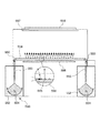
図1Aは、本発明の第1実施形態の光照射装置の斜視図である。 FIG. 1A is a perspective view of the light irradiation apparatus according to the first embodiment of the present invention.
この光照射装置は、面状照射するようになっている。詳しくは、この光照射装置は、光源1、リフレクタ2、集光レンズ3、導光体4および反射体6を備え、光源1から出射した光は、リフレクタ2および集光レンズ3によって集光されて導光体4の中に案内されるようになっている。
This light irradiating device is configured to irradiate a surface. Specifically, this light irradiation device includes a
上記導光体4は、直方体状の形状を有し、光出射面77と、溝形成面78とを有する。上記溝形成面78は、導光体4の底面を構成する。上記溝形成面78は、溝部5を有し、溝部5は、複数の溝55を有する。上記導光体4に入射した光は、溝部5で反射して、底面に対向する面側に進行し、光照射装置の照射面9に照射されるようになっている。上記導光体4の光源1側とは反対側の端面10は、ミラー面となっている。この光照射装置は、1灯配置の構成を有している。
The light guide 4 has a rectangular parallelepiped shape, and has a
図1Bは、導光体4の側面図であり、導光体4の溝形状を示す図である。 FIG. 1B is a side view of the light guide 4 and shows a groove shape of the light guide 4.
図1Bに示すように、上記各溝55の形状は、断面略二等辺三角形状であり、その二等辺三角形一方の底角φ1は、他方の底角φ2と等しくなっている。
As shown in FIG. 1B, the shape of each
例えば、上記底角φ1が、30°である場合に、図1Bの側面において、溝形成面78(他の表現をすると、導光体4と周囲との界面S)に略平行に進行する光について考える。上記導光体4の導光板材料が合成石英(屈折率Nd:1.46)で臨界角が43度である場合、溝部5への入射光(導光体4の伝搬光)Iinは、溝55の斜面に対する入射角θ1が全反射条件を満たし、全反射されて照射光Ir1となる。このような全反射した照射光は、各溝55から発せられて、照射面9に照射する。このようにして、面状照射を行う。
For example, when the base angle φ1 is 30 °, the light that travels substantially parallel to the groove forming surface 78 (in other words, the interface S between the light guide 4 and the periphery) on the side surface of FIG. 1B. think about. When the light guide plate material of the light guide 4 is synthetic quartz (refractive index Nd: 1.46) and the critical angle is 43 degrees, the incident light (propagation light of the light guide 4) Iin to the groove 5 is a groove. The incident angle θ1 with respect to the slope of 55 satisfies the total reflection condition, and is totally reflected to become the irradiation light Ir1. Such totally reflected irradiation light is emitted from each
上記各溝55は、三角柱状の形状を有し、各溝55の形状は、図1Bの紙面に垂直な方向に一様であり、導光体4の奥行き方向に一様である。断面二等辺三角形状の溝55の深さを、0.1mmに設定すると共に、導光体4の厚さを、15mmに設定した場合、上記溝を約5mm間隔で均等に配置することで、照射面において、平均照度±2%以下の照度均一性を、解析的に獲得できる。
Each
第1実施形態では、上記反射体6を、導光体4の下に配置している。このようにして、導光体4の溝形成時の誤差等によって、反射体6を導光体4の下に配置しなかったならば顕著であったであろう照射面9(図1A参照)での照度ムラを抑制し、設計通りの照度均一性を獲得するようにしている。
In the first embodiment, the
図1Aに示すように、上記導光体4は、支持基板7に支持ピット8で支持されている。上記導光体4と、支持基板7との間には、スペースが存在している。上記反射体6は、上記スペースにおいて照射面9の照度調整をしたい部分の照度調整が可能な箇所に配置されている。詳しくは、上記光源1からの光であって反射体6で反射した反射光が、照射面9の所望の部分に照射されるように、反射体6を配置するようになっている。
As shown in FIG. 1A, the light guide 4 is supported on a support substrate 7 by
光源1からの光であって導光体4内を進行する光は、導光体4の光出射面77から抜け出る他、導光体4の溝形成面78からも抜け出る。例えば、溝55の斜面88(図1B参照)の法線方向に進行して、斜面に入射する光は、導光体4の溝形成面78から抜け出ることになる。
The light traveling from the
以下、図1Bにおいて紙面の右側に位置する部分を用いて、反射体6の機能について説明する。
Hereinafter, the function of the
上記導光体4内を進行する光の一部は、溝55の光源1(図1A参照)側の斜面を出た後、溝55の他方の斜面から再度導光体4に入射する。この再度の導光体4への入射時に、反射光Ir2が発生する。この反射光Ir2は、反射体6で反射され、その反射光Ir3が照射面9(図1A参照)に向けて照射されることになる。第1実施形態では、上記再度の導光体4への入射の際に発生する反射光Ir2を、照度均一化のために用いているのである。
A part of the light traveling in the light guide 4 exits the slope on the light source 1 (see FIG. 1A) side of the
上記反射体6は、反射光Ir3光が作製誤差による照射面9の照射ずれが大きい部分に向けて照射されるように配置する。例えば、溝が、導光体の伝搬光を50%全反射する一方、他の伝搬光を溝55の斜面から外に一旦出射するという条件、すなわち、導光体4の材料が合成石英で、屈折率Ndが1.46であり、溝の深さが0.1mmであり、かつ、斜面の斜度φ1、φ2が30°という条件の場合、反射体6から反射され、再度照射光として用いることのできる照射角度範囲、すなわち、溝55で反射されて反射体6に到達し、さらに反射体6で反射後、再度導光体の出射面に到達した位置に、点光源があるとみなし、その到達位置の出射面に対する法線を中心に、導光体4から出射する光Ir3が照射面9を見込む厚さ方向の角度範囲は、角度選択、すなわち、溝の斜面の角度φ1、φ2を導光体の伝搬光が全て全反射とならないように設定するという角度選択を設けない場合に対して半分の±22.5°の角度範囲となる。この場合、照射面9と導光体4との距離hが100mmで、かつ、反射体6で反射させる領域のサイズが0.1mm角である場合、1箇所の反射体が照射する範囲は、82mm角の範囲になる。したがって、82mm角の範囲を、その照度調整範囲として設定することができる。
The
このことを逆に考えれば、所望の照度調整範囲、例えば、82mm角の調整範囲を、調整するべく、反射体6の位置を定めることで、この範囲での照度の調整をすることができる。
Considering this in reverse, the illuminance can be adjusted within this range by determining the position of the
尚、上記第1実施形態では、1灯配置の構成を有していたが、この発明では、図1Cに示すように、2灯配置の構成を取ることもできる。すなわち、図1Cに示すように、光を、導光体104の両側から入射させることもできる。2灯配置のほうが照度均一化時の溝部の配置誤差の影響を受けにくくなる。したがって、2灯配置のほうが、均一化を行う溝部105の配置設計の際に、設計時の公差を大きく取ることができる。尚、図1Cにおいて、101は、光源であり、102は、リフレクタであり、103は、集光レンズである。また、106は、反射体であり、107は、支持基板であり、108は、支持ピットである。
In addition, in the said 1st Embodiment, although it had the structure of 1 lamp arrangement | positioning, in this invention, as shown to FIG. 1C, the structure of 2 lamp arrangement | positioning can also be taken. That is, as shown in FIG. 1C, light can be incident from both sides of the
また、上記第1実施形態では、導光体4は、直方体形状であったが、この発明では、導光体は、六面体等、直方体以外の如何なる形状をとることもできる。 Moreover, in the said 1st Embodiment, although the light guide 4 was a rectangular parallelepiped shape, in this invention, a light guide can take any shapes other than a rectangular parallelepiped, such as a hexahedron.
図2Aは、第2実施形態の光照射装置の側面図である。 FIG. 2A is a side view of the light irradiation apparatus of the second embodiment.
第2実施形態では、集光レンズ213のNAを小さくして、光源211からの出射光を、リフレクタ212を介して導光体204に入射させるようにしている。使用するレンズは、焦点距離が200mmで、有効範囲が110mmで、NA=0.26である。尚、ここで、NA(numerical aperture)は、レンズの開口数であり、レンズの分解能を表す指数である。http://ja.wikipedia.org/wiki/%E3%83%95%E3%82%A1%E3%82%A4%E3%83%AB:Numerical_aperture.svg
In the second embodiment, the NA of the condensing
このようにして、上記集光レンズ13からの入射光の角度範囲を、導光体の光が入射する面の法線に対して、導光体の厚み方向になす角を±15°の範囲に制限するようにしている。また、導光体を合成石英で形成して、導光体4の内部を伝搬する角度を、±10°以下に制限している。 In this way, the angle range of the incident light from the condenser lens 13 with respect to the normal of the surface on which the light of the light guide is incident is in the range of ± 15 ° in the thickness direction of the light guide. I try to limit it to Further, the light guide is made of synthetic quartz, and the angle of propagation inside the light guide 4 is limited to ± 10 ° or less.
また、第2実施形態では、上記導光体204が合成石英からなり、かつ、溝部215の各溝の斜面の斜度φ1、φ2を、45°にしている。このことから、図2Aの部分拡大断面図である図2Bに示すように、反射体206の反射面290および導光体204の長手方向の両方に垂直な平面の法線方向に進行する伝搬光が、溝255で全反射して、導光体204の光出射面277の略法線方向に進行するようになっている。
In the second embodiment, the
上記溝255の斜度φ1、φ2が45°の場合には、溝部255において全反射角で反射される成分Ir1は、溝部205に入射する光に対する割合は65%であり、残りの成分は溝255の斜面から導光体204の外部に漏れる。この結果、導光体204の外部に漏れて再度、照射面に対して照射される角度範囲、すなわち、溝255面から漏れて、反射面290に到達、反射面290で反射後に導光体204の光出射面277に到達して、導光体204から出射される光Ir3が、その到達点における導光体204の光出射面277の法線に対して、導光板の厚さ方向になす角度の範囲が±6°以下(全角度成分、すなわち、導光体204に入射された時点で制限された伝搬角で決まる、導光板厚さ方向の角度成分、±15°の35%以下)に設定することができる。したがって、一旦導光体204の外部に漏れた後、再度照射面に入射する光を照度調整に用いた場合の光の照射範囲を、さらに絞ることができて、光の照度ムラを、より局所的にピンポイントに調整することができる。
When the slopes φ1 and φ2 of the
例えば、反射体で反射される領域のサイズが0.1mm角である場合、照射面と導光体との距離が400mmの場合であっても、84mm角の範囲を、その照度調整範囲とすることができる。 For example, when the size of the area reflected by the reflector is 0.1 mm square, even if the distance between the irradiation surface and the light guide is 400 mm, the range of 84 mm square is the illuminance adjustment range. be able to.
また、上記反射体206において導光体204からの出射方向が照射される部分において、多層膜反射ミラー216を用いることで、反射体206における反射光に角度選択性、すなわち、多層膜反射ミラー216への入射光のうち、全てを反射するのではなく、予め設定された入射角(多層反射ミラーに対する)に与えることができる。詳しくは、上記導光体4から反射体6へ向けて出射する光のうち、再度、導光体4へ反射する光Ir2が±6°以下に角度制限されている場合において、多層反射ミラー16の多層膜の層数を増やし、反射時の角度選択性をさらに±3°以下に抑制する。このようにすると、照射面と導光体との距離が400mmの場合で、反射ミラー16で反射される領域のサイズが0.1mm角である場合、照射面9における照射範囲を、42mm角まで小さくできる。
Further, by using the multilayer
尚、第2実施形態では、反射面を反射体6の全面に形成しておいて、一部に別の反射特性(入射角依存性)を持つ多層膜反射ミラー16を配置する構造になっている。尚、この発明では、反射ミラーとして、多層膜反射ミラー以外のものを使用することもできる。
In the second embodiment, the reflection surface is formed on the entire surface of the
第2実施形態のように、反射ミラーを局所的に配置する場合は、反射体6が反射率、すなわち反射面290への入射光に対して、導光体側に反射される率を予め部分的に変えた反射体206を配置する場合に比べて以下の利点がある。すなわち、照度調整は設計からのずれに対応するもので、予測した照度ずれと異なる場合に、予め反射率を変えて、その状態が固定化するならば対応できない。一方で、反射体206全体で溝255からの反射光Ir2を一定の反射率で反射する構成にしておき、更に、照度調整したい照度範囲に対応する位置に、反射率を上下させた多層膜反射ミラー216を形成する。このようにすれば、照度調整を重点的に行う側と、重点的に行わない側の両方で、適切に照度調整を行うことができる。上記反射体206の反射面において多層膜反射ミラー216と間隔をおいて位置する部分は、第1部分を構成し、多層膜反射ミラー216の導光体206側の表面は、第2部分を構成している。
When the reflecting mirror is locally arranged as in the second embodiment, the reflectance of the
このように反射体6の反射率に角度依存性を持つ部位を形成した場合、照度調整範囲をより狭めることができ、より局所的な照度のばらつきを補正することができる。したがって、照度の均一化を好適に実現することができる。
Thus, when the site | part which has an angle dependence in the reflectance of the
尚、この発明では、図2Bにおける多層膜反射ミラー216の位置に、多層膜反射ミラー216の代わりに角度選択性のある吸収体を設ける構成にしても良い。このようにすると、反射体に入射した光のうち、ある角度範囲の光を吸収することができて、多層膜反射ミラー使用時と同じように、反射体での反射光を照度調整に利用する際に、特定角度範囲の光を減衰させる形で、照度調整範囲を狭くすることができる。尚、角度選択性のある吸収体としては、深溝(照射波長の3倍以上の深さ)の金属製グレーティングを形成した吸収素子等を使用することができる。
In the present invention, an absorber having an angle selectivity may be provided instead of the
第2実施形態によれば、反射体206から図示しない照射面(図1Aに9で示す面に対応する面)に向けて進行する光の立体角の範囲をより狭めることができて、照射面での照度の補正の範囲をより効果的に絞り込むことができる。
According to the second embodiment, the range of the solid angle of light traveling from the
尚、多層膜反射ミラー16の代わりに角度選択性のある吸収体を設ける構成にした場合、再反射光量は、反射強度Ir3から減衰して、(1−α)・Ir3(吸収率:α)になる。尚、このとき、照度調整時の変化量は、αIr3となる。 In addition, when it is set as the structure which provides an absorber with an angle selectivity instead of the multilayer film reflective mirror 16, the amount of re-reflections attenuate | damps from reflection intensity Ir3, (1- (alpha)) * Ir3 (absorption rate: (alpha)) become. At this time, the amount of change when adjusting the illuminance is αIr3.
図3Aは、第3実施形態の光照射装置の側面図である。また、図3Bは、図3Aの部分拡大断面図である。 FIG. 3A is a side view of the light irradiation apparatus of the third embodiment. FIG. 3B is a partially enlarged sectional view of FIG. 3A.
第3実施形態では、図3Bに示すように、反射体306の一部に溝355から出た光の光路を直接に遮断する防止部の一例としての構造体336を、反射体306上に形成している。このようにして、直接に照射面(図示せず)を照射する光量を制限する。
In the third embodiment, as shown in FIG. 3B, a
このようにすると、反射体に入射する光の光量を変化させずに、反射体の反射率を変える場合よりも、大きい光量の範囲の調整を行うことができる。 In this way, it is possible to adjust the range of a larger amount of light than when changing the reflectance of the reflector without changing the amount of light incident on the reflector.
詳しくは、反射体上に構造体が存在していない場合、調整用光の光量は、導光体材料が合成石英の場合で、溝の斜面から一旦導光体の外に出る光量が50%の場合、最大でも調整光Ir3は、漏れ光の約2.5%である。一方、第3実施形態では、同じく一旦、溝355から導光体304の外に出る光量割合が50%の場合であって、更に、反射体306がフレネル反射による損失だけで損失させる透明構造体である場合であっても、調整光Ir3、すなわち、反射面で反射した光の光量として、漏れ光の約5%の光量を確保できる。尚、構造体336による遮断率を上げれば、調整光量を大きくすることができる。
Specifically, when there is no structure on the reflector, the amount of light for adjustment is 50% when the light guide material is synthetic quartz, and the amount of light that temporarily goes out of the light guide from the groove slope is 50%. In this case, the adjustment light Ir3 is about 2.5% of the leakage light at the maximum. On the other hand, in the third embodiment, similarly, the ratio of the amount of light emitted from the
尚、第3実施形態では、反射体306上に形成した突出部としての構造体336によって光を遮断しているが、構造体336の反射体306の反射面からの高さを変えることでも、遮光量を変えることができる。
In the third embodiment, the light is blocked by the
図4Aは、第4実施形態の光照射装置の側面図である。また、図4Bは、図4Aの変形例の部分拡大断面図である。 FIG. 4A is a side view of the light irradiation apparatus of the fourth embodiment. FIG. 4B is a partially enlarged cross-sectional view of a modification of FIG. 4A.
図4A,4Bに示すように、反射体406上に、反射体406とは別体の第2反射体416を設けて、第2反射体416の高さを適宜変動させるようにしても良い。このようにしても、溝455で屈折するか、または、その他の部分で屈折するかを変更できて、照射面(図示せず)への照射範囲を変動させることができる。
As shown in FIGS. 4A and 4B, a second reflector 416 separate from the
すなわち、例えば、部分反射体446(図4B参照)から照射面に向かう光のうち、溝455を通る光、それ以外を通る光が存在するように、部分反射体446の高さを調整する。そして、反射光のうち溝455を通る光だけ、照射面側に出射し、それ以外のところを通る光は、遮光体447(図4B参照)で遮光する。この場合にも、照度調整のために、反射体406から反射する光の照射範囲を実効的に制限できて、照度調整範囲を絞り込むことができる。
That is, for example, the height of the
このように、上記反射体406の反射位置の高さを変えることでも、照度調整範囲を変動させることができて、照度ムラを調整する調整精度を上げることができる。図4Bを参照して、溝形成面の溝455が形成されていない部分から紙面の左側の部分反射体446までの距離は、第1距離を構成し、溝形成面の溝455が形成されていない部分から紙面の右側の部分反射体446までの距離は、第2距離を構成している。
As described above, by changing the height of the reflection position of the
図5は、本発明の第5実施形態の検査装置を示す図である。 FIG. 5 is a diagram showing an inspection apparatus according to the fifth embodiment of the present invention.
この検査装置は、太陽電池の検査を行うようになっている。この検査装置は、光照射装置590と、測定物配置部材の一例としての検査板557とを備え、光照射装置590は、反射部材550、二つの光源551、リフレクタ552、伝搬角変更テーパ部553、導光体(導光板)554、および、反射体556を有する。上記導光板554には、複数の溝555が形成されている。
This inspection apparatus inspects solar cells. This inspection apparatus includes a
上記各光源551は、棒状光源である。上記各光源551からの光を、集光用のリフレクタ552で集光する。また、集光された光が、導光体554に結合する前に、伝搬角変更用のテーパ部553で、集光された光の導光体554への入射角を制限している。このようにして、その集光された光の導光体554内での伝搬角の範囲も狭くなるようにしている。
Each
上記テーパ部553は入射端の開口が出射端の開口よりも小さくなっている。この検査装置では、光源551から、導光体554までの光路途中に、波長特性(波長ごとに強度が変化する放射スペクトルに合わせた特性等)をコントロールする光学フィルタ(図示せず)を配置している。このようにして、導光板554に入る前に、光の波長特性を制御している。なお、光源の種類は複数種でも良く、また、光源として2灯以外の灯、例えば、3灯以上の灯を配置しても良い。このような場合であっても、光を導光体に導入する前に、反射部材のところに光路合成部材を用いることで、これら複数の光源の出射光を導光体に同時に入射することができる。
The tapered
上記検査板557は、導光体554から400mm離れた位置に配置されている。上記検査板557の上には、検査されるべき太陽電池558が搭載されるようになっている。光は、導光体554から太陽電池558に向けて照射されるようになっている。上記反射体556の一部に、反射率を変えた部分を形成することで、太陽電池558に向けて照射する照度の均一性を高くすることができる。
The
1,101,211,311,411,551 光源
2,102,212,312,412,552 リフレクタ
3,103,213,313,413 集光レンズ
4,104,204,305,404,554 導光体
5 溝部
6,106,206,306,406,556 反射体
46 部分反射体
55,255,355,455,555 溝
1,101,211,311,411,551 Light source 2,102,212,312,412,552 Reflector 3,103,213,313,413 Condensing lens 4,104,204,305,404,554 Light guide 5 Groove 6,106,206,306,406,556 Reflector 46 Partial reflector 55,255,355,455,555 Groove
Claims (6)
光が出射される光出射面と、この光出射面に対向すると共に、一方向に互いに間隔をおいて位置する複数の溝が形成された溝形成面とを有する導光体と、
上記光源からの光を上記導光体に案内する光学部材と、
上記導光体の上記溝形成面に対向する反射面を有する反射体と
を備え、
上記導光体の上記各溝は、上記一方向を法線とする平面に対して傾斜する傾斜面を有し、
上記光源からの光のうちの一部の光は、上記傾斜面で反射して上記反射面に到達すると共に、上記一部の光であって、上記反射面で反射した光の少なくとも一部は、上記導光体の上記光出射面に到達し、
上記反射体の上記反射面は、上記光源からの光の一部であって上記溝の上記傾斜面で反射する光が到達可能な第1部分と、この第1部分に対して間隔をおいて位置すると共に、上記傾斜面以外の面から反射された光が入射する第2部分とを有し、
上記第1部分の光の反射率は、上記第2部分の光の反射率と異なることを特徴とする光照射装置。 A light source;
A light guide having a light emitting surface from which light is emitted, and a groove forming surface formed with a plurality of grooves facing the light emitting surface and spaced apart from each other in one direction;
An optical member for guiding light from the light source to the light guide;
A reflector having a reflecting surface facing the groove forming surface of the light guide,
Each groove of the light guide has an inclined surface that is inclined with respect to a plane whose normal is the one direction,
A part of the light from the light source is reflected by the inclined surface and reaches the reflecting surface, and at least a part of the light reflected by the reflecting surface is the part of the light. Reaching the light exit surface of the light guide ,
The reflecting surface of the reflector is a part of the light from the light source and can be reached by light reflected by the inclined surface of the groove, and is spaced from the first part. And a second portion on which light reflected from a surface other than the inclined surface is incident,
The reflectance of light of the first portion, the light irradiation apparatus according to claim Rukoto different from the reflectance of light of the second portion.
光が出射される光出射面と、この光出射面に対向すると共に、一方向に互いに間隔をおいて位置する複数の溝が形成された溝形成面とを有する導光体と、
上記光源からの光を上記導光体に案内する光学部材と、
上記導光体の上記溝形成面に対向する反射面を有する反射体と
を備え、
上記導光体の上記各溝は、上記一方向を法線とする平面に対して傾斜する傾斜面を有し、
上記光源からの光のうちの一部の光は、上記傾斜面で反射して上記反射面に到達すると共に、上記一部の光であって、上記反射面で反射した光の少なくとも一部は、上記導光体の上記光出射面に到達し、
上記反射体の上記反射面は、上記光源からの光の一部であって上記溝の上記傾斜面で反射する光が到達可能な第1部分と、この第1部分に対して間隔をおいて位置すると共に、上記傾斜面以外の面から反射された光が入射する第2部分とを有し、
上記第1部分の反射率は、上記第1部分に入射する光の入射角に基づいて変動する角度依存性を有すると共に、上記第2部分の反射率は、上記第2部分に入射する光の入射角に基づいて変動する角度依存性を有し、
上記第1部分の反射率の角度依存性は、上記第2部分の反射率の角度依存性と異なることを特徴とする光照射装置。 A light source;
A light guide having a light emitting surface from which light is emitted, and a groove forming surface formed with a plurality of grooves facing the light emitting surface and spaced apart from each other in one direction;
An optical member for guiding light from the light source to the light guide;
A reflector having a reflecting surface facing the groove forming surface of the light guide;
With
Each groove of the light guide has an inclined surface that is inclined with respect to a plane whose normal is the one direction,
A part of the light from the light source is reflected by the inclined surface and reaches the reflecting surface, and at least a part of the light reflected by the reflecting surface is the part of the light. Reaching the light exit surface of the light guide,
The reflecting surface of the reflector is a part of the light from the light source and can be reached by light reflected by the inclined surface of the groove, and is spaced from the first part. And a second portion on which light reflected from a surface other than the inclined surface is incident ,
The reflectance of the first part has an angle dependency that varies based on the incident angle of the light incident on the first part, and the reflectance of the second part is the reflectance of the light incident on the second part. It has an angle dependency that varies based on the incident angle,
The light irradiation apparatus according to claim 1, wherein the angle dependency of the reflectance of the first portion is different from the angle dependency of the reflectance of the second portion.
上記光源からの光であって上記傾斜面で反射して上記反射面に向かう光の一部が、上記反射面に到達することを防止する防止部を備えることを特徴とする光照射装置。 In the light irradiation apparatus of Claim 1 or 2 ,
A light irradiation apparatus comprising: a prevention unit that prevents a part of light from the light source that is reflected by the inclined surface and travels toward the reflection surface from reaching the reflection surface.
上記反射面は、
上記溝形成面において上記溝から間隔をおいて位置する部分との距離が、第1距離である第1距離部と、
上記溝形成面において上記溝から間隔をおいて位置する部分との距離が、第1距離よりも大きい第2距離である第2距離部と
を有することを特徴とする光照射装置。 In the light irradiation apparatus as described in any one of Claim 1 to 3 ,
The reflective surface is
A distance between the groove forming surface and a portion located at a distance from the groove is a first distance portion, which is a first distance;
A light irradiation apparatus comprising: a second distance portion that is a second distance that is larger than the first distance in a distance from a portion that is spaced from the groove on the groove forming surface.
上記光学部材は、上記光源からの光であって上記導光体に案内される光が上記導光体の上記光出射面に入射する際の最大の入射角が、上記光出射面の全反射の臨界角よりも大きくなるように、上記光源からの光の進路を制限し、
上記溝の上記斜面が上記導光体の上記光出射面に対してなす角の角度および上記最大の入射角の角度で、上記光源からの光の一部であって上記溝の上記傾斜面と上記反射面で反射して上記光出射面に到達した光の照射範囲を制限することによって、上記光出射面から出射される光が上記光出射面の出射位置によらずより一様に近づくように照射することを特徴とする光照射装置。 In the light irradiation apparatus as described in any one of Claim 1 to 4 ,
The optical member has a maximum incident angle when light from the light source and guided to the light guide is incident on the light exit surface of the light guide. Limiting the path of light from the light source to be greater than the critical angle of
The angle formed by the inclined surface of the groove with respect to the light exit surface of the light guide and the angle of the maximum incident angle is a part of light from the light source and the inclined surface of the groove By limiting the irradiation range of the light reflected by the reflecting surface and reaching the light emitting surface, the light emitted from the light emitting surface approaches more uniformly regardless of the emitting position of the light emitting surface. The light irradiation apparatus characterized by irradiating.
上記導光体から出射される光の出射範囲内に位置すると共に、透明材料からなる測定物配置部材と、
上記光源からの光であって上記導光体を経由して上記測定物配置部材に到達する光の波長毎の強度を変動させる光学フィルタと
を備えることを特徴とする検査装置。 The light irradiation device according to any one of claims 1 to 5 ,
Located within the emission range of light emitted from the light guide, and a measurement object arrangement member made of a transparent material,
An inspection apparatus comprising: an optical filter that fluctuates intensity for each wavelength of light from the light source and reaching the measurement object arranging member via the light guide.
Priority Applications (1)
| Application Number | Priority Date | Filing Date | Title |
|---|---|---|---|
| JP2009106435A JP5178617B2 (en) | 2009-04-24 | 2009-04-24 | Light irradiation device and inspection device |
Applications Claiming Priority (1)
| Application Number | Priority Date | Filing Date | Title |
|---|---|---|---|
| JP2009106435A JP5178617B2 (en) | 2009-04-24 | 2009-04-24 | Light irradiation device and inspection device |
Publications (2)
| Publication Number | Publication Date |
|---|---|
| JP2010257749A JP2010257749A (en) | 2010-11-11 |
| JP5178617B2 true JP5178617B2 (en) | 2013-04-10 |
Family
ID=43318455
Family Applications (1)
| Application Number | Title | Priority Date | Filing Date |
|---|---|---|---|
| JP2009106435A Expired - Fee Related JP5178617B2 (en) | 2009-04-24 | 2009-04-24 | Light irradiation device and inspection device |
Country Status (1)
| Country | Link |
|---|---|
| JP (1) | JP5178617B2 (en) |
Families Citing this family (1)
| Publication number | Priority date | Publication date | Assignee | Title |
|---|---|---|---|---|
| JP6043005B2 (en) * | 2016-02-17 | 2016-12-14 | 株式会社三共 | Game machine |
Family Cites Families (11)
| Publication number | Priority date | Publication date | Assignee | Title |
|---|---|---|---|---|
| JPH08334765A (en) * | 1995-06-09 | 1996-12-17 | Matsushita Electric Ind Co Ltd | Surface light source device and liquid crystal display formed by using the same |
| JP2003215589A (en) * | 1997-03-28 | 2003-07-30 | Sharp Corp | Forward illumination device and reflecting type liquid crystal display device equipped with it |
| JP3874224B2 (en) * | 1997-09-12 | 2007-01-31 | インターナショナル・ビジネス・マシーンズ・コーポレーション | Light guide unit and liquid crystal display device for increasing polarization component |
| JP2002109932A (en) * | 2000-10-03 | 2002-04-12 | Enplas Corp | Flat light source device and image display device |
| JP2002324420A (en) * | 2001-04-18 | 2002-11-08 | Internatl Business Mach Corp <Ibm> | Surface light source apparatus, display device and reflection sheet |
| JP2003077323A (en) * | 2001-09-05 | 2003-03-14 | Goyo Paper Working Co Ltd | Well-proportioned surface light emitting device |
| JP4043285B2 (en) * | 2002-05-21 | 2008-02-06 | シチズン電子株式会社 | Backlight unit |
| JP2004287368A (en) * | 2003-01-27 | 2004-10-14 | Tokyo Electron Ltd | Inspecting device |
| JP2006227408A (en) * | 2005-02-18 | 2006-08-31 | Alps Electric Co Ltd | Liquid crystal display |
| JP2007213972A (en) * | 2006-02-09 | 2007-08-23 | Seiko Instruments Inc | Lighting system and display device provided with it |
| JP2009043574A (en) * | 2007-08-09 | 2009-02-26 | Hitachi Maxell Ltd | Optical device, and liquid crystal display device |
-
2009
- 2009-04-24 JP JP2009106435A patent/JP5178617B2/en not_active Expired - Fee Related
Also Published As
| Publication number | Publication date |
|---|---|
| JP2010257749A (en) | 2010-11-11 |
Similar Documents
| Publication | Publication Date | Title |
|---|---|---|
| JP5314653B2 (en) | Light irradiation device, simulated solar light irradiation device, solar cell panel inspection device | |
| JP4570680B1 (en) | Light irradiation device and inspection device | |
| JP4865883B2 (en) | Light source device and pseudo-sunlight irradiation device provided with the same | |
| US20120275132A1 (en) | Pseudo-Sunlight Irradiating Apparatus | |
| KR100818280B1 (en) | Surface light emitting device and display device using the same | |
| JP5310946B2 (en) | Solar simulator and solar cell inspection device | |
| TW201706726A (en) | Critical dimension variation correction in extreme ultraviolet lithography | |
| JP5178617B2 (en) | Light irradiation device and inspection device | |
| JP5887981B2 (en) | Ultraviolet irradiation device and illuminance adjustment method | |
| KR20160127080A (en) | Line light source and optical line sensor unit | |
| JP5178610B2 (en) | Light irradiation device | |
| KR20120112387A (en) | Pseudo sunlight emitting device | |
| JP2011003475A (en) | Pseudo-sunlight irradiating device | |
| JP5274528B2 (en) | Pseudo-sunlight irradiation device and solar panel inspection device | |
| CN113892022A (en) | Light source and biochemical analyzer | |
| JP5355525B2 (en) | Pseudo-sunlight irradiation device and solar panel inspection device | |
| JP5049375B2 (en) | Simulated solar irradiation device | |
| WO2013038769A1 (en) | Artificial-sunlight projection device | |
| JP7265370B2 (en) | line lighting source | |
| CN115701527A (en) | Light detection device and light irradiation device | |
| CN118092078A (en) | Illumination optical system, exposure apparatus, irradiation method, and method for manufacturing component | |
| KR101978663B1 (en) | Reflecting structure of lighting optics | |
| TW202306689A (en) | Light irradiation device | |
| JP2019132799A (en) | Measuring device and measuring method | |
| JP2006214917A (en) | Method and device for detecting defect of substrate |
Legal Events
| Date | Code | Title | Description |
|---|---|---|---|
| A621 | Written request for application examination |
Free format text: JAPANESE INTERMEDIATE CODE: A621 Effective date: 20110310 |
|
| A977 | Report on retrieval |
Free format text: JAPANESE INTERMEDIATE CODE: A971007 Effective date: 20120713 |
|
| A131 | Notification of reasons for refusal |
Free format text: JAPANESE INTERMEDIATE CODE: A131 Effective date: 20120731 |
|
| A521 | Written amendment |
Free format text: JAPANESE INTERMEDIATE CODE: A523 Effective date: 20120926 |
|
| A01 | Written decision to grant a patent or to grant a registration (utility model) |
Free format text: JAPANESE INTERMEDIATE CODE: A01 Effective date: 20121218 |
|
| A61 | First payment of annual fees (during grant procedure) |
Free format text: JAPANESE INTERMEDIATE CODE: A61 Effective date: 20130108 |
|
| LAPS | Cancellation because of no payment of annual fees |