JP5163031B2 - Electronic camera - Google Patents
Electronic camera Download PDFInfo
- Publication number
- JP5163031B2 JP5163031B2 JP2007249803A JP2007249803A JP5163031B2 JP 5163031 B2 JP5163031 B2 JP 5163031B2 JP 2007249803 A JP2007249803 A JP 2007249803A JP 2007249803 A JP2007249803 A JP 2007249803A JP 5163031 B2 JP5163031 B2 JP 5163031B2
- Authority
- JP
- Japan
- Prior art keywords
- image
- electronic camera
- cpu
- value
- signal
- Prior art date
- Legal status (The legal status is an assumption and is not a legal conclusion. Google has not performed a legal analysis and makes no representation as to the accuracy of the status listed.)
- Expired - Fee Related
Links
- 238000003384 imaging method Methods 0.000 claims description 78
- 239000000203 mixture Substances 0.000 claims description 46
- 230000015572 biosynthetic process Effects 0.000 claims description 39
- 238000003786 synthesis reaction Methods 0.000 claims description 39
- 238000004364 calculation method Methods 0.000 claims description 19
- 230000002194 synthesizing effect Effects 0.000 claims description 9
- 238000005375 photometry Methods 0.000 claims description 6
- 238000009826 distribution Methods 0.000 claims description 2
- 238000000034 method Methods 0.000 description 86
- 230000008569 process Effects 0.000 description 84
- 238000012545 processing Methods 0.000 description 80
- 238000012986 modification Methods 0.000 description 33
- 230000004048 modification Effects 0.000 description 33
- 230000035945 sensitivity Effects 0.000 description 25
- 239000002131 composite material Substances 0.000 description 22
- 238000009825 accumulation Methods 0.000 description 17
- 238000001514 detection method Methods 0.000 description 12
- 230000003287 optical effect Effects 0.000 description 9
- 238000006243 chemical reaction Methods 0.000 description 8
- 229920006395 saturated elastomer Polymers 0.000 description 7
- 208000003443 Unconsciousness Diseases 0.000 description 6
- 238000010586 diagram Methods 0.000 description 6
- 230000000694 effects Effects 0.000 description 5
- 230000004044 response Effects 0.000 description 5
- 238000012790 confirmation Methods 0.000 description 4
- 238000003825 pressing Methods 0.000 description 4
- 230000006641 stabilisation Effects 0.000 description 4
- 238000011105 stabilization Methods 0.000 description 4
- 238000012937 correction Methods 0.000 description 3
- 238000003860 storage Methods 0.000 description 3
- 230000004397 blinking Effects 0.000 description 2
- 230000003247 decreasing effect Effects 0.000 description 2
- 230000006870 function Effects 0.000 description 2
- XLYOFNOQVPJJNP-UHFFFAOYSA-N water Substances O XLYOFNOQVPJJNP-UHFFFAOYSA-N 0.000 description 2
- 230000003321 amplification Effects 0.000 description 1
- 230000008859 change Effects 0.000 description 1
- 239000012141 concentrate Substances 0.000 description 1
- 238000005314 correlation function Methods 0.000 description 1
- 238000000605 extraction Methods 0.000 description 1
- 210000004709 eyebrow Anatomy 0.000 description 1
- 230000014509 gene expression Effects 0.000 description 1
- 239000004973 liquid crystal related substance Substances 0.000 description 1
- 238000003199 nucleic acid amplification method Methods 0.000 description 1
- 238000002360 preparation method Methods 0.000 description 1
- 239000004065 semiconductor Substances 0.000 description 1
- 238000012546 transfer Methods 0.000 description 1
Images


Classifications
-
- H—ELECTRICITY
- H04—ELECTRIC COMMUNICATION TECHNIQUE
- H04N—PICTORIAL COMMUNICATION, e.g. TELEVISION
- H04N23/00—Cameras or camera modules comprising electronic image sensors; Control thereof
- H04N23/70—Circuitry for compensating brightness variation in the scene
-
- H—ELECTRICITY
- H04—ELECTRIC COMMUNICATION TECHNIQUE
- H04N—PICTORIAL COMMUNICATION, e.g. TELEVISION
- H04N23/00—Cameras or camera modules comprising electronic image sensors; Control thereof
- H04N23/70—Circuitry for compensating brightness variation in the scene
- H04N23/71—Circuitry for evaluating the brightness variation
-
- H—ELECTRICITY
- H04—ELECTRIC COMMUNICATION TECHNIQUE
- H04N—PICTORIAL COMMUNICATION, e.g. TELEVISION
- H04N23/00—Cameras or camera modules comprising electronic image sensors; Control thereof
- H04N23/70—Circuitry for compensating brightness variation in the scene
- H04N23/743—Bracketing, i.e. taking a series of images with varying exposure conditions
Landscapes
- Engineering & Computer Science (AREA)
- Multimedia (AREA)
- Signal Processing (AREA)
- Studio Devices (AREA)
- Image Processing (AREA)
Description
本発明は、電子カメラに関する。 The present invention relates to an electronic camera.
複数の画像を合成するカメラが知られている(特許文献1参照)。 A camera that synthesizes a plurality of images is known (see Patent Document 1).
従来技術では、カメラ自身に画像合成の要否を判断させることが困難で、合成不要な場合にも無駄な処理を行うおそれがあった。 In the prior art, it is difficult for the camera itself to determine whether image synthesis is necessary, and there is a possibility that useless processing may be performed even when synthesis is not necessary.
請求項1に記載の電子カメラは、被写体像を撮像して画像信号を出力する撮像素子と、前記撮像素子によって異なる撮像条件で撮像された複数の画像信号を用いて1つの画像を生成する画像合成手段と、所定の判定条件に基づいて、前記画像合成手段に対して前記画像合成の可否を制御する制御手段と、前記画像信号を用いて測光演算する測光手段と、を備え、前記撮像素子は、前記画像合成手段で用いられる前記複数の画像信号を撮像する前に、互いに異なる撮像条件で撮像された複数のプレビュー画像信号を出力し、前記測光手段は、前記各プレビュー画像信号を用いて測光演算を行い、前記制御手段は、前記複数のプレビュー画像信号に対する前記測光演算で得られた最大輝度値と最小輝度値との差の段数に基づいて、前記画像合成に用いられる前記複数の画像の数を決定することを特徴とする。
請求項2に記載の電子カメラは、請求項1に記載の電子カメラにおいて、前記制御手段は、前記複数のプレビュー画像信号に対する前記測光演算で得られた画像の明るさ分布に基づいて、前記画像合成の可否を制御することを特徴とする。
請求項3に記載の電子カメラは、請求項2に記載の電子カメラにおいて、前記制御手段は、前記差の段数に基づいて、前記画像合成の可否を制御することを特徴とする。
請求項4に記載の電子カメラは、請求項1〜3の何れか一項に記載の電子カメラにおいて、前記画像合成手段が用いる前記複数の画像信号は、撮影指示に応じて前記撮像素子が毎秒数十〜数百フレームのフレームレートで取得したものであることを特徴とする。
請求項5に記載の電子カメラは、請求項1に記載の電子カメラにおいて、前記制御手段は、前記測光演算によって得られる画像の平均的な明るさに基づいた撮像条件で前記撮像素子が撮像した前記プレビュー画像信号の最大値または最小値に基づいて、前記画像合成の可否を制御することを特徴とする。
請求項6に記載の電子カメラは、請求項1〜請求項5のいずれか一項に記載の電子カメラにおいて、前記制御手段は、設定されている撮影モードに応じて前記画像合成の可否を制御することを特徴とする。
請求項7に記載の電子カメラは、請求項1〜請求項6のいずれか一項に記載の電子カメラにおいて、前記画像合成手段は、前記画像合成に用いる複数の画像のそれぞれの信号値の範囲より広い信号値の範囲を有する1つの画像を生成することを特徴とする。
The electronic camera according to
The electronic camera according to
According to a third aspect of the present invention, in the electronic camera according to the second aspect, the control means controls whether or not the image composition is possible based on the number of steps of the difference.
The electronic camera according to a fourth aspect is the electronic camera according to any one of the first to third aspects, wherein the image pickup device uses the image pickup device in response to a shooting instruction. It is obtained at a frame rate of several tens to several hundred frames.
The electronic camera according to claim 5 is the electronic camera according to
The electronic camera according to claim 6 is the electronic camera according to any one of
The electronic camera according to claim 7 is the electronic camera according to any one of
本発明によれば、適切に画像合成を行う電子カメラが得られる。 According to the present invention, an electronic camera that appropriately performs image composition can be obtained.
以下、図面を参照して本発明を実施するための最良の形態について説明する。
(第一の実施形態)
図1は、本発明の第一の実施形態による電子カメラの構成を例示するブロック図である。図1において、電子カメラは、撮像光学系11と、撮像素子12と、AFE(Analog front end)回路13と、画像処理部14と、バッファメモリ15と、記録インターフェース(I/F)16と、モニタ17と、操作部材18と、半押しスイッチ19aと、全押しスイッチ19bと、メモリ20と、CPU21と、ズームレンズ駆動装置25と、防振レンズ駆動装置26と、振れセンサ50とを備える。
The best mode for carrying out the present invention will be described below with reference to the drawings.
(First embodiment)
FIG. 1 is a block diagram illustrating the configuration of the electronic camera according to the first embodiment of the invention. In FIG. 1, an electronic camera includes an imaging
CPU21、メモリ20、記録インターフェース16、画像処理部14、バッファメモリ15、およびモニタ17は、それぞれがバス22を介して接続されている。
The
撮像光学系11は、ズームレンズやフォーカシングレンズ、防振レンズを含む複数のレンズ群で構成され、被写体像を撮像素子12の受光面に結像させる。なお、図1を簡単にするため、撮像光学系11を単レンズとして図示している。
The imaging
撮像素子12は、受光面に受光素子が二次元配列されたCMOSイメージセンサなどによって構成される。撮像素子12は、撮像光学系11を通過した光束による被写体像を光電変換してアナログ画像信号を生成する。アナログ画像信号は、AFE回路13に入力される。
The
AFE回路13は、アナログ画像信号に対するゲイン調整(指示されたISO感度に応じた信号増幅など)を行う。具体的には、CPU21からの感度設定指示に応じて撮像感度(露光感度)を所定範囲(たとえばISO50相当〜ISO3200相当)内で変更する。撮像感度は、相当するISO値で表されることからISO感度と呼ばれる。AFE回路13はさらに、内蔵するA/D変換回路によってアナログ処理後の画像信号をデジタルデータに変換する。デジタル画像データは、画像処理部14に入力される。
The
画像処理部14は、デジタル画像データに対して各種の画像処理(色補間処理、階調変換処理、輪郭強調処理、ホワイトバランス調整処理など)の他、後述する画像合成処理を施す。
The
バッファメモリ15は、画像処理部14による画像処理の前工程や後工程での画像データを一時的に記憶する。記録インターフェース16はコネクタ(不図示)を有し、該コネクタに記録媒体23が接続される。記録インターフェース16は、接続された記録媒体23に対するデータの書き込みや、記録媒体23からのデータの読み込みを行う。記録媒体23は、半導体メモリを内蔵したメモリカード、またはハードディスクドライブなどで構成される。
The
モニタ17は液晶パネルによって構成され、CPU21からの指示に応じて画像や操作メニューなどを表示する。操作部材18は、モードダイヤル、十字キー、決定ボタンなどを含む。操作部材18は、モード切替え操作やメニュー選択操作など、各操作に応じた操作信号をCPU21へ送出する。
The
半押しスイッチ19aおよび全押しスイッチ19bは、レリーズボタン(不図示)の押下操作に連動して、それぞれがオン信号をCPU21へ出力する。スイッチ19aからのオン信号(半押し操作信号)は、レリーズボタンが通常ストロークの半分程度まで押し下げ操作されると出力され、半ストロークの押し下げ操作解除で出力が解除される。スイッチ19bからのオン信号(全押し操作信号)は、レリーズボタンが通常ストロークまで押し下げ操作されると出力され、通常ストロークの押し下げ操作が解除されると出力が解除される。半押し操作信号は、CPU21に対して撮影準備の開始を指示する。全押し操作信号は、CPU21に対して記録用画像の取得開始を指示する。
The half-push switch 19a and the full-push switch 19b each output an ON signal to the
CPU21は、ROM(不図示)に格納されたプログラムを実行することによって電子カメラが行う動作を統括的に制御する。CPU21は、AF(オートフォーカス)動作制御や自動露出(AE)演算、オートホワイトバランス演算などを行う。AF動作は、たとえば、プレビュー画像のコントラスト情報に基づいてフォーカシングレンズ(不図示)の合焦位置を求めるコントラスト検出方式を用いる。プレビュー画像(スルー画像とも称す)は、撮影指示される前に撮像素子12が取得するモニタ用画像(所定の間引き率で間引きされた画像)のことをいう。なお、コントラスト検出方式でなく、位相差検出方式によるオートフォーカス調節を行うように構成しても構わない。
The
CPU21は、顔検出部24としても機能する。顔検出部24は、プレビュー画像に含まれる顔領域を検出する。顔検出処理は、公知の特徴点抽出処理によって眉、目、鼻、唇の各端点などの特徴点を抽出し、抽出した特徴点に基づいて顔領域か否かを判定する。なお、プレビュー画像とあらかじめ用意した参照データ(顔画像など)との相関関数を求め、この関数が所定の判定閾値を超えた場合に顔領域と判定するように構成してもよい。
The
振れセンサ50は、電子カメラのヨー方向およびピッチ方向の振れをそれぞれ検出し、各検出信号をCPU21へ送信する。
The
防振レンズ駆動装置26は、CPU21からの指示に応じて撮影光学系11を構成する防振レンズ(不図示)を光軸と直交する向きへ進退移動させる。CPU21は、振れセンサ50からの検出信号に基づいて、検出された振れの影響を打ち消すように防振レンズ駆動指示を防振レンズ駆動装置26へ送る。これにより、電子カメラの揺動に起因する撮像素子12上における被写体像の相対的な揺れが抑えられる。
The anti-vibration
ズームレンズ駆動装置25は、CPU21からの指示に応じて撮影光学系11を構成するズームレンズ(不図示)を光軸方向に進退移動させる。CPU21は、操作部材18からのズーム操作信号に応じてズームレンズ駆動指示をズームレンズ駆動装置25へ送る。
The zoom
本実施形態の電子カメラは、複数の画像を合成した画像を記録する撮影モードを有する。画像合成を許可する「合成オート」モードに設定された電子カメラは、撮影時に合成要否を判定し、合成必要を判定した場合に複数の画像を取得して合成し、合成画像を記録する。複数の画像(レリーズボタンの全押し操作で取得される本画像)の取得は、たとえば、数十フレーム/毎秒のフレームレート(たとえば80fps)で行う。一方、合成必要を判定しない場合には通常撮影と同様に1画像を取得して記録する。「合成オート」モードは、モードダイヤル操作によって電子カメラに設定される。 The electronic camera of this embodiment has a shooting mode for recording an image obtained by combining a plurality of images. The electronic camera set to the “composite auto” mode that permits image composition determines whether or not composition is necessary at the time of shooting, and if it is determined that composition is necessary, acquires and composes a plurality of images and records the composite image. Acquisition of a plurality of images (main images acquired by fully pressing the release button) is performed, for example, at a frame rate of several tens of frames / second (for example, 80 fps). On the other hand, if it is not determined that synthesis is necessary, one image is acquired and recorded in the same manner as in normal shooting. The “composite auto” mode is set in the electronic camera by a mode dial operation.
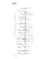
電子カメラが「合成オート」モードに設定された場合に行う処理の流れについて、図2のフローチャートを参照して説明する。CPU21は、「合成オート」モードに設定されると図2のレリーズ待機処理を行うプログラムを起動する。
A flow of processing performed when the electronic camera is set to the “composite auto” mode will be described with reference to a flowchart of FIG. When the “composite auto” mode is set, the
<レリーズ待機処理>
レリーズ待機処理では、数十〜百数十フレーム/毎秒のフレームレート(たとえば60fps〜120fps)でプレビュー画像を繰り返し取得して後述する露出演算やフォーカス調節を行うとともに、プレビュー画像をモニタ17に逐次表示させながらレリーズ操作を待つ。なお、電子カメラはプレビュー画像を構成する信号値を用いて測光演算を行うため、プレビュー画像取得時の撮像感度を前フレームで取得した信号値に応じて適宜変更する。しかしながら、画像の平均的な明るさに応じた撮像感度で取得したフレームの画像を選択してモニタ17に表示することにより、モニタ17に表示される画像の明るさが不自然に変動することを防止している。
<Release standby processing>
In the release standby process, a preview image is repeatedly acquired at a frame rate of several tens to hundreds of tens of frames / second (for example, 60 fps to 120 fps), exposure calculation and focus adjustment described later are performed, and the preview image is sequentially displayed on the
図2のステップS10において、CPU21は半押し操作判定を行う。CPU21は、半押しスイッチ19aから半押し操作信号を受けるとステップS10を肯定判定してステップS20へ進む。CPU21は、半押し操作信号を受けない場合にはステップS10を否定判定し、当該判定処理を繰り返す。
In step S10 of FIG. 2, the
ステップS20において、CPU21はプレビュー画像を構成する画像信号値に基づいて自動露出演算(AE)を行ってステップS30へ進む。この自動露出演算では、たとえば、画像の平均的な明るさに基づいて撮像条件(撮像感度、蓄積時間および絞り値)を決定する。本実施形態では、撮像時の信号蓄積時間をいわゆる電子シャッタによって制御する。ステップS30において、CPU21は、プレビュー画像から得られるコントラスト情報に基づいてオートフォーカス調節を行ってステップS40へ進む。
In step S20, the
ステップS40において、CPU21は画像合成の要否を判定する。図3は、ステップS20において取得した、後述する3つのプレビュー画像信号(互いに撮像条件を変えた3回のプレビュー撮影動作で得た画像)から得られるヒストグラムを例示する図である。横軸は明るさ(信号レベル)を表し、縦軸はデータ数を表す。CPU21は、各画素位置に対応する信号について、明るい(暗い)ものから順に並べて図3のヒストグラムを得る。
In step S40, the
撮像素子12のような蓄積型のセンサを用いる場合、ダイナミックレンジはA/D変換の精度(すなわちビット長)に依存する。たとえば、8ビット長でA/D変換する場合のダイナミックレンジは、Ev値で6段程度である。この場合、たとえばEv1〜Ev20の範囲の全域について1回の撮像(測光)によって適切な値の画像信号を得ることは困難であるため、被写体の明るさに応じて撮像レンジを変更する。撮像レンジの変更は、ステップS20で決定した撮像感度および蓄積時間の少なくとも一方を変化させることによって行う。本実施形態では、絞り値を上記ステップS20で決定した値に固定しておき、撮像感度や蓄積時間を変化させて撮像レンジを変えながら、合成レリーズ処理(ステップS80において後述)を行う。この合成レリーズ処理と同様に互いの撮像条件を変えながら複数回のプレビュー画像の取得動作を行う方法について以下に述べる。
When a storage type sensor such as the
CPU21は、画像の平均的な明るさに基づいて決定した撮像条件で撮像したプレビュー画像(第1のプレビュー画像)の画素信号のうち、信号レベルが飽和している(たとえば8ビット長の場合に信号値が255超)画素位置のものは、撮像感度を下げて(または蓄積時間を短くして)飽和しないようにして撮像した別のプレビュー画像(第2のプレビュー画像)の対応する画素位置の信号と置換する。このとき、プレビュー画像間における感度差(蓄積時間差)を加味した上で置換する。これにより、プレビュー画像の最も明るい領域の信号が、いわゆる白飛びのない状態で得られる。なお、白飛びとは、たとえば図3にBxで示したように、ある明るさにおいてデータ数が収束していない(所定数未満となっていない)状態でヒストグラムが切れている場合を示す。
The
反対に、画像の平均的な明るさに基づいて決定した撮像条件で撮像したプレビュー画像(第1のプレビュー画像)の画素信号のうち、信号レベルが所定値以下のものは、撮像感度を上げて(または蓄積時間を長くして)所定値以上となるようにして撮像した別のプレビュー画像(第3のプレビュー画像)の対応する画素位置の信号と置換する。このとき、プレビュー画像間における感度差(蓄積時間差)を加味した上で置換する。これにより、プレビュー画像の最も暗い領域の信号が、いわゆる黒つぶれのない状態で得られる。なお、黒つぶれとは、たとえば図3にByで示したように、ある暗さにおいてデータ数が収束していない(所定数未満となっていない)状態でヒストグラムが切れている場合を示す。このようにして得られた上記3つのプレビュー画像に基づいて図3に示したヒストグラムが得られる。このヒストグラムは後述するステップS50で用いる。 On the contrary, among the pixel signals of the preview image (first preview image) imaged under the imaging condition determined based on the average brightness of the image, those having a signal level equal to or lower than a predetermined value increase the imaging sensitivity. It replaces with a signal at a corresponding pixel position of another preview image (third preview image) taken so as to be equal to or greater than a predetermined value (or by increasing the accumulation time). At this time, replacement is performed in consideration of sensitivity difference (accumulation time difference) between preview images. As a result, the signal in the darkest area of the preview image can be obtained without so-called blackout. Note that blackout indicates a case where the histogram is cut off in a state where the number of data does not converge (is less than a predetermined number) in a certain darkness, for example, as indicated by By in FIG. The histogram shown in FIG. 3 is obtained based on the three preview images thus obtained. This histogram is used in step S50 described later.
ステップS40の判定を行うCPU21は、画像の平均的な明るさに基づいて決定した撮像条件で撮像したプレビュー画像(第1のプレビュー画像)の画素信号に上述した白飛びも黒つぶれも生じていない場合は、ステップS40を否定判定してステップS90へ進む。ステップS90へ進む場合は合成不要を判定する場合である。
The
CPU21は、画像の平均的な明るさに基づいて決定した撮像条件で撮像したプレビュー画像の画素信号に上述した白飛びおよび黒つぶれの少なくとも一方が生じている場合には、ステップS40を肯定判定してステップS50へ進む。ステップS50へ進む場合は合成必要を判定する場合である。
When at least one of the above-described overexposure and underexposure occurs in the pixel signal of the preview image captured under the image capturing condition determined based on the average brightness of the image, the
ステップS50において、CPU21は合成条件を決定する。合成条件は、合成のために取得する画像の数と、各画像を取得する際の撮像条件とを含む。CPU21は、たとえば、上述のようにして得られたヒストグラム(図3)の最高輝度データBhと最低輝度データBlとの差が8段あれば、最大Ev値と、最大Ev値より8段低いEv値と、この間を補間するEv値でそれぞれ画像を取得する。具体的には、(1)最大Ev値と、(2)最大Ev値より2段低いEv値と、(3)最大Ev値より4段低いEv値と、(4)最大Ev値より8段低いEv値とを決定する。この場合、合成のために取得する画像の数は、8(BhとBlの差)/2(補間ステップ)=4である。
In step S50, the
最大Ev値は以下のように決定する。CPU21は、最高輝度値Bhをダイナミックレンジに含むように、最高輝度値Bhに対して所定のマージンΔBを加えた輝度B(B=Bh+ΔB)に応じてシャッター速度Tvおよび/または撮像感度Svを決定する(絞りAvは上述したように所定値)。本実施形態の場合、シャッター速度Tvの高速側上限は、たとえば1/80秒とする。このように決定した(Tv+Av)は最大Ev値に対応する。最大Ev値では、たとえば、太陽などの高輝度領域の画素信号は飽和しない(いわゆる白飛びをしない)ものの、他の領域の画素信号は画像の平均的な明るさより暗くなる。
The maximum Ev value is determined as follows. The
次にCPU21は、Ev値を最大Ev値から2段低くする。具体的には、シャッター速度Tvおよび/または撮像感度Svを変える(絞りは上述した値に固定)。Ev値を2段下げると、太陽などの高輝度領域の画素信号が飽和するものの、画像の平均的な明るさの領域の画素信号の信号値が高まる。
Next, the
同様にCPU21は、Ev値を最大Ev値から4段低くする。シャッター速度Tvおよび/または撮像感度Svを変えて(絞りは上述した値に固定)Ev値を4段下げると、画像の平均的な明るさの領域の画素信号の信号値がさらに高まる。
Similarly, the
CPU21はさらに、Ev値を最大Ev値から8段低くする。シャッター速度Tvおよび/または撮像感度Svを変えて(絞りは上述した値に固定)Ev値を8段下げると、画像の平均的な明るさを有する領域の画素信号レベルは高いものの、画像の暗領域の画素信号は所定値以上の値が得られる(いわゆる黒つぶれをしない)。
Further, the
CPU21は、以上のように合成条件を決定したらステップS60へ進む。ステップS60において、CPU21は半押し操作が解除されたか否かを判定する。CPU21は、半押しスイッチ19aからの半押し操作信号が入力されていない場合はステップS60を肯定判定してステップS10へ戻り、上述した処理を繰り返す。CPU21は、半押しスイッチ19aからの半押し操作信号が入力されている場合はステップS60を否定判定し、ステップS70へ進む。
If CPU21 determines a synthetic | combination condition as mentioned above, it will progress to step S60. In step S60, the
ステップS70において、CPU21は全押し操作判定を行う。CPU21は、全押しスイッチ19bから全押し操作信号を受けるとステップS70を肯定判定してステップS80へ進む。CPU21は、全押し操作信号を受けない場合にはステップS70を否定判定してステップS60へ戻る。
In step S70, the
ステップS80において、CPU21は、合成時レリーズ処理を行ってステップS10へ戻る。合成時レリーズ処理の詳細については後述する。
In step S80, the
上述したステップS40を否定判定して進むステップS90において、CPU21は半押し操作が解除されたか否かを判定する。CPU21は、半押しスイッチ19aからの半押し操作信号が入力されていない場合はステップS90を肯定判定してステップS10へ戻り、上述した処理を繰り返す。CPU21は、半押しスイッチ19aからの半押し操作信号が入力されている場合はステップS90を否定判定し、ステップS100へ進む。
In step S90, which is determined by making a negative determination in step S40 described above, the
ステップS100において、CPU21は全押し操作判定を行う。CPU21は、全押しスイッチ19bから全押し操作信号を受けるとステップS100を肯定判定してステップS110へ進む。CPU21は、全押し操作信号を受けない場合にはステップS100を否定判定してステップS90へ戻る。
In step S100, the
ステップS110において、CPU21は、通常時レリーズ処理を行ってステップS10へ戻る。通常時レリーズ処理の詳細については後述する。
In step S110, the
<合成時レリーズ処理>
合成時レリーズ処理の流れについて、図4のフローチャートを参照して説明する。図4のステップS81において、CPU21は撮像条件をセットしてステップS82へ進む。具体的には、ステップS50(図2)において決定した内容で、撮像素子12の蓄積時間およびAFE回路13の利得(撮像感度)をセットする。ステップS82において、CPU21は撮像素子12に撮像させてステップS83へ進む。これにより、セットされた撮像条件で撮像(本画像の取得動作)が行われ、蓄積信号がAFE回路13を介して画像処理部14へ転送される。
<Release processing during synthesis>
The flow of the release process at the time of composition will be described with reference to the flowchart of FIG. In step S81 in FIG. 4, the
ステップS83において、CPU21は所定回数の撮像を終了したか否かを判定する。CPU21は、合成のために取得する画像数に対応する回数(本例では4)の撮像を終了した場合にステップS83を肯定判定してステップS84へ進む。CPU21は、上記撮像回数に満たない場合にはステップS83を否定判定してステップS81へ戻り、所定回数に達するまで撮像を繰り返す。これにより、1撮影指示(全押し操作信号入力)に応じて、Ev値を4通りに変えながら画像1〜画像4まで4画像が取得される。図5は、取得する画像1〜画像4についてのEv値の大小を例示する図である。図5において、画像2は、画像1に比べて−2段のEv値で取得された画像である。画像3は、画像1に比べて−4段のEv値で取得された画像である。画像4は、画像1に比べて−8段のEv値で取得された画像である。なお、図5は撮影指示が出される度に(全押し操作がなされる度に)、上述の一連の撮影(Ev値を変えながらの4回の撮像)が行われることを示している。
In step S83, the
ステップS84において、CPU21は画像処理部14へ指示を送り、取得した画像を合成させる。画像処理部14は、図3のヒストグラムに基づいて明るさを4つの範囲に分け、以下のように合成処理を行う。なお、4つの範囲の境界周辺の画素位置に対応する領域には、境界継ぎ目が目立たないように境界処理を施す。なお、合成は、色補間処理を施して各画素位置に各色(たとえばRGB)のデータを有する画像を用いて行う。
(a)最も明るい範囲に含まれる画素位置に対応する領域を画像1によるデータで表す。
(b)2番目に明るい範囲に含まれる画素位置に対応する領域を画像2によるデータで表す。
(c)3番目に明るい範囲に含まれる画素位置に対応する領域を画像3によるデータで表す。
(d)4番目に明るい(最も暗い)範囲に含まれる画素位置に対応する領域を画像4によるデータで表す。
In step S84, the
(a) An area corresponding to a pixel position included in the brightest range is represented by data based on the
(b) An area corresponding to a pixel position included in the second brightest range is represented by data based on the
(c) A region corresponding to a pixel position included in the third brightest range is represented by data based on the image 3.
(d) A region corresponding to a pixel position included in the fourth brightest (darkest) range is represented by data based on the
図6は、合成後の画像を説明する図である。図中「画像1」の領域は、画像1によるデータで表されていることを示す。「画像2」の領域は、画像2によるデータで表されていることを示す。また、「画像3」の領域は、画像3によるデータで表されていることを示す。さらに、「画像4」の領域は、画像4によるデータで表されていることを示す。
FIG. 6 is a diagram for explaining the combined image. The area of “
画像処理部14は、以上のように合成処理を行った後に(図6の合成画像データに)階調変換処理、輪郭強調処理、ホワイトバランス調整処理を行う。CPU21は、画像処理が終了するとステップS85へ進む。ステップS85において、CPU21は、処理後の画像データ(合成画像データ)を記録媒体23へ保存する処理を開始させてステップS86へ進む。ステップS86において、CPU21は、処理後の合成画像データをモニタ17に表示させる処理を開始させて図4による処理を終了する。
The
<通常時レリーズ処理>
通常時レリーズ処理の流れについて、図7のフローチャートを参照して説明する。通常時のレリーズ処理では、ステップS20の露出演算で得られる制御露出値に基づいて1画像を取得する。図7のステップS111において、CPU21は撮像条件をセットしてステップS112へ進む。具体的には、ステップS20で取得されている制御露出にしたがって撮像素子12の蓄積時間およびAFE回路13の利得、絞り(不図示)の絞り値をセットする。通常時レリーズ処理では、絞り優先自動露出モードのように電子カメラに設定されている絞り値で露出を制御する場合を除き、絞りも制御対象に含めて制御する。
<Normal release process>
The flow of the normal release process will be described with reference to the flowchart of FIG. In the normal release process, one image is acquired based on the control exposure value obtained by the exposure calculation in step S20. In step S111 in FIG. 7, the
ステップS112において、CPU21は撮像素子12に撮像させてステップS113へ進む。これにより、セットされた撮像条件で撮像が行われ、蓄積信号がAFE回路13を介して画像処理部14へ転送される。画像処理部14は、転送データに色補間処理、階調変換処理、輪郭強調処理、ホワイトバランス調整処理などを行う。
In step S112, the
ステップS113において、CPU21は、処理後の画像データを記録媒体23へ保存する処理を開始させてステップS114へ進む。ステップS114において、CPU21は、処理後の画像データをモニタ17に表示させる処理を開始させて図7による処理を終了する。
In step S113, the
CPU21は、「合成時レリーズ処理」を行う場合、撮影条件としてモニタ17に表示するシャッター速度の値は、次のように表示させる。たとえば、合成のために取得する画像数が4であって、画像1〜画像4のシャッター速度Tvが全て1/80秒の場合(撮像素子12の画像取得のフレームレートが80fpsの場合)、CPU21は、(1/80+1/80+1/80+1/80)=1/20秒を表示させる。
When performing the “release process during composition”, the
以上説明した第一の実施形態によれば、次の作用効果が得られる。
(1)電子カメラが「合成時レリーズ処理」を行うか「通常時レリーズ処理」を行うかを自動的に決定するので、手動で切り換える場合と異なり、ユーザーは撮影操作に専念できる。
According to the first embodiment described above, the following operational effects can be obtained.
(1) Since the electronic camera automatically determines whether to perform “release process at the time of composition” or “release process at the time of normal operation”, unlike when switching manually, the user can concentrate on the shooting operation.
(2)「合成時レリーズ処理」では、1撮影指示(全押し操作信号入力)に応じて複数の画像を高いフレームレート(数十〜数百フレーム/毎秒)で取得するので、いわゆるブラケット撮影の場合と異なり、ユーザーは1コマ撮影と同様の感覚で撮影操作を行うことができる。 (2) “Release processing during compositing” acquires a plurality of images at a high frame rate (several tens to several hundred frames / second) in response to one shooting instruction (full-press operation signal input). Unlike the case, the user can perform the shooting operation with the same feeling as in the single frame shooting.
(3)ヒストグラム(図3)に基づいて複数の画像をEv値を変えながら取得するので、1回の撮像(測光)のダイナミックレンジを超える広範囲(たとえばEv1〜Ev20)の撮影に対応が可能である。つまり、明るい被写体領域も暗い被写体領域も、複数の画像のいずれかで適切な信号値の画像として取得できるので、白飛びや黒つぶれがない画像が得られる。 (3) Since a plurality of images are acquired while changing the Ev value based on the histogram (FIG. 3), it is possible to cope with a wide range (for example, Ev1 to Ev20) exceeding the dynamic range of one imaging (photometry). is there. That is, since a bright subject area and a dark subject area can be acquired as an image having an appropriate signal value in any of a plurality of images, an image without whiteout or blackout can be obtained.
(4)撮像素子12で取得したプレビュー画像を構成する信号値を用いて測光演算を行うようにしたので、撮像素子12と別個に測光センサを設ける場合に比べてコスト低減および実装スペースの縮小に効果が得られる。
(4) Since the photometric calculation is performed using the signal value constituting the preview image acquired by the
(5)ヒストグラム(図3)に基づいて被写界の明るさを複数(たとえば4つ)の範囲に分け、最も明るい範囲に含まれる画素位置に対応する領域を画像1によるデータで表し、2番目に明るい範囲に含まれる画素位置に対応する領域を画像2によるデータで表し、3番目に明るい範囲に含まれる画素位置に対応する領域を画像3によるデータで表し、4番目に明るい(最も暗い)範囲に含まれる画素位置に対応する領域を画像4によるデータで表すように上記複数の画像から1つの画像を生成するとともに、4つの範囲の境界周辺の画素位置に対応する領域に境界処理を施すように合成処理を行うので、広ダイナミックレンジで高品質の画像が得られる。
(5) The brightness of the object scene is divided into a plurality of (for example, four) ranges based on the histogram (FIG. 3), and the region corresponding to the pixel position included in the brightest range is represented by data from
(6)合成処理のために取得する画像数を、撮影指示前(ステップS20)に取得したヒストグラム(図3)の最高輝度データBhと最低輝度データBlとの差に基づいて決めるので、レリーズ全押し操作前に画像取得に見込まれる時間を求め、モニタ17に表示させることができる。
(6) Since the number of images to be acquired for the composition process is determined based on the difference between the maximum luminance data Bh and the minimum luminance data B1 in the histogram (FIG. 3) acquired before the shooting instruction (step S20), all the releases The time expected for image acquisition before the push operation can be obtained and displayed on the
(変形例1)
電子カメラが「合成時レリーズ処理」を行うか「通常時レリーズ処理」を行うかを自動的に決定する「合成オート」モードを備える例を説明したが、手動操作によって「合成時レリーズ処理」を行うか「通常時レリーズ処理」を行うかを切り換える構成にしてもよい。たとえば、切換可能なモードダイヤル上に「合成モード」を設けておき、このモードダイヤルの切換操作によって「合成時レリーズ処理」を選択するようにしてもよい。
(Modification 1)
Although an example has been provided with the “Composite Auto” mode in which the electronic camera automatically determines whether to perform “Release processing during synthesis” or “Release processing during normal operation”, the “Release processing during synthesis” can be performed manually. It may be configured to switch between performing and “normal release process”. For example, a “composite mode” may be provided on a switchable mode dial, and “release process during compositing” may be selected by switching the mode dial.
(変形例2)
電子カメラが「合成時レリーズ処理」を行うか「通常時レリーズ処理」を行うかを自動決定する際(ステップS40)、画像の平均的な明るさに基づくプレビュー画像の画素信号に白飛び、黒つぶれが生じるか否かに応じて行う例を説明した。この代わりに、ヒストグラム(図3)の最高輝度データBhと最低輝度データBlとの差が所定段数を超えるか否かに応じて上記自動決定を行うようにしてもよい。この場合、たとえば、最高輝度データBhと最低輝度データBlとの差が所定値(撮像素子自身のもつダイナミックレンジを示す値で本実施例の場合は6段)を超えた場合に「合成必要」を決定し、「合成時レリーズ処理」を行うように制御する。
(Modification 2)
When the electronic camera automatically determines whether to perform “combination release processing” or “normal release processing” (step S40), the pixel signal of the preview image based on the average brightness of the image is over-exposed and black-out. The example performed according to whether crushing arises was demonstrated. Instead of this, the automatic determination may be performed according to whether or not the difference between the highest luminance data Bh and the lowest luminance data Bl in the histogram (FIG. 3) exceeds a predetermined number of steps. In this case, for example, when the difference between the maximum luminance data Bh and the minimum luminance data Bl exceeds a predetermined value (a value indicating the dynamic range of the image pickup device itself, which is six steps in this embodiment), “combining is necessary”. And control to perform “release process at the time of composition”.
(変形例3)
また、電子カメラが「合成時レリーズ処理」を行うか「通常時レリーズ処理」を行うかを自動決定する際(ステップS40)、自動露出演算(ステップS20)の結果に応じて上記自動決定を行うようにしてもよい。変形例3のCPU21は、画像の平均的な明るさに基づいて決定した蓄積時間が、いわゆる手ぶれ限界秒時より低速側である場合に「合成必要」を決定し、「合成時レリーズ処理」を行うように制御する。これにより、被写体が暗くて黒つぶれが生じるおそれがある場合であっても蓄積時間を制限した「合成時レリーズ処理」を行うことで、手ブレの生じない画像を得つつ、広ダイナミックレンジで高品質の画像が得られる。
(Modification 3)
Further, when the electronic camera automatically determines whether to perform “combination release processing” or “normal release processing” (step S40), the automatic determination is performed according to the result of the automatic exposure calculation (step S20). You may do it. The
(変形例4)
「合成オート」モードにおいて、電子カメラが「合成時レリーズ処理」を行うか「通常時レリーズ処理」を行うかを自動決定する場合、主要被写体の動きがあるか否かを判定し、この判定結果に応じて上記自動決定を行うようにしてもよい。
(Modification 4)
In “Composite Auto” mode, when the electronic camera automatically decides whether to perform “Release processing during synthesis” or “Release processing during normal operation”, it determines whether there is any movement of the main subject, and this determination result Depending on the above, the above automatic determination may be performed.
変形例4のCPU21は、プレビュー画像のコマ間の被写体画像の変化量が所定の判定閾値以上か否かを判定する。たとえば、前コマのプレビュー画像と当コマのプレビュー画像のデータから算出されるコマ間(フレーム間)の動きベクトルの大きさが所定値以上の場合、被写体の動きがあると判定する。被写体の動きがある場合は「合成不要」を決定し、「合成時レリーズ処理」を行わずに「通常時レリーズ処理」を行うように制御する。動いている被写体を撮影する場合は「通常時レリーズ処理」を行うことで、合成による像ブレの可能性を皆無に制御できる。
The
(変形例5)
電子カメラが「合成時レリーズ処理」を行うか「通常時レリーズ処理」を行うかを自動決定する場合、設定されている撮影モードに応じて上記自動決定を行うようにしてもよい。変形例5のCPU21は、撮影モードが「スポーツシーン」モードか否かを判定する。たとえば、「スポーツシーン」を撮影するモードの場合は「合成不要」を決定し、「合成時レリーズ処理」を行わずに「通常時レリーズ処理」を行うように制御する。動きのある被写体を撮影する場合は「通常時レリーズ処理」を行うことで、合成による像ブレの可能性を排除できる。
(Modification 5)
When the electronic camera automatically determines whether to perform the “combination release process” or “normal release process”, the automatic determination may be performed according to the set shooting mode. The
(変形例6)
変形例6のCPU21は、撮影モードが「遠景(風景)」モードか否かを判定する。たとえば、「遠景」を撮影するモードの場合は「合成必要」を決定し、「合成時レリーズ処理」を行うように制御する。風景撮影など、明暗を適切に表現したい場合に「合成時レリーズ処理」を行うことで、広ダイナミックレンジで高品質の画像が得られる。また、風景には被写体として動体が入る率は低いので、合成による像ブレの影響が合成画像に発生する可能性が低い。
(Modification 6)
The
(変形例7)
変形例7のCPU21は、撮影モードが「ポートレート」モードか否かを判定する。たとえば、「ポートレート」を撮影するモードの場合は上記遠景モードと同様に被写体として動体が入る可能性が低いことが予想されるので「合成必要」を決定し、「合成時レリーズ処理」を行うように制御する。
(Modification 7)
The
(変形例8)
「合成オート」モードにおいて、電子カメラが「合成時レリーズ処理」を行うか「通常時レリーズ処理」を行うかを自動決定する場合、電池残量を判定し、この判定結果に応じて上記自動決定を行うようにしてもよい。
(Modification 8)
In the “Composite Auto” mode, when the electronic camera automatically determines whether to perform “Release processing during synthesis” or “Release processing during normal operation”, the remaining battery level is determined, and the above automatic determination is made according to the determination result. May be performed.
変形例8のCPU21は、不図示の電池電圧検出回路による検出結果に基づいて電池残量が所定値以下か否かを判定する。電池残量が所定値以下の場合は「合成不要」を決定し、「合成時レリーズ処理」を行わずに「通常時レリーズ処理」を行うように制御する。電池残量が少ない場合に撮像する回数を減らすことや合成処理を行わないようにすることで、消費電力を抑えることができる。
The
(変形例9)
「合成オート」モードにおいて、電子カメラが「合成時レリーズ処理」を行うか「通常時レリーズ処理」を行うかを自動決定する場合、撮影位置情報および撮影日時情報を用いて上記自動決定を行うようにしてもよい。
(Modification 9)
In “Composite Auto” mode, when the electronic camera automatically decides whether to perform “Release Process at Compositing” or “Release Process at Normal Time”, the above automatic decision should be made using the shooting position information and the shooting date / time information. It may be.
変形例9のCPU21は、不図示のGPS装置を用いて取得した位置情報、およびCPU21が内蔵する計時回路から取得した日時情報に基づいて合成要否を判定する。たとえば、夏季の海辺、または冬季の山間部のようなダイナミックレンジの広い被写体であることが予想される場合は「合成必要」を決定し、「合成時レリーズ処理」を行うように制御する。明暗を適切に表現したい場合に「合成時レリーズ処理」を行うことで、広ダイナミックレンジで高品質の画像が得られる。
The
(変形例10)
「合成オート」モードにおいて、電子カメラが「合成時レリーズ処理」を行うか「通常時レリーズ処理」を行うかを自動決定する場合、電子カメラに露出補正が指示されているか否かに応じて上記自動決定を行うようにしてもよい。変形例10のCPU21は、たとえば、露出補正が指示されている場合に「合成不要」を決定し、「合成時レリーズ処理」を行わずに「通常時レリーズ処理」を行うように制御する。広ダイナミックレンジ化の処理を行わないことで、ユーザーが意図する露出補正効果を得ることができる。
(Modification 10)
In the “Composite Auto” mode, when automatically determining whether the electronic camera performs the “release process during composition” or the “release process during normal operation”, the above is performed depending on whether exposure correction is instructed to the electronic camera. Automatic determination may be performed. For example, when exposure correction is instructed, the
(変形例11)
「合成オート」モードにおいて、電子カメラが「合成時レリーズ処理」を行うか「通常時レリーズ処理」を行うかを自動決定する場合、振れセンサ50からの検出信号に基づいて上記自動決定を行うようにしてもよい。変形例11のCPU21は、振れセンサ50による検出値が防振制御範囲を超える(防振レンズを駆動させても振れの影響を打ち消すことが困難)場合に「合成必要」を決定し、一撮影指示で得られた複数の画像の中から手ブレしていない画像を抽出して合成するために「合成時レリーズ処理」を行うように制御する。
(Modification 11)
In the “composite auto” mode, when the electronic camera automatically determines whether to perform “release process during synthesis” or “release process during normal operation”, the above automatic determination is performed based on the detection signal from the
(変形例12)
以上の説明では、「合成時レリーズ処理」を行う場合に画像の全域について合成するようにしたが、画像の一部を合成処理の対象にしてもよい。たとえば、画像の中央を中心とした所定範囲や、フォーカス調節の対象とした所定範囲を合成処理の対象にする。画像全域を合成する場合に比べて、合成処理時の負担を軽減できる。
(Modification 12)
In the above description, when the “release process at the time of composition” is performed, the entire area of the image is composed. However, a part of the image may be a target of the composition process. For example, a predetermined range centered on the center of the image or a predetermined range targeted for focus adjustment is set as the target of the synthesis process. Compared to the case where the entire image is synthesized, the burden during the synthesis process can be reduced.
(変形例13)
上述した説明では、全押し操作信号を受け付け後に取得した複数の画像を用いて画像を合成する例を説明したが、半押し操作信号を受け付け後に連続的な、あるいは所定間隔おきに繰り返される画像(全押し操作で得られる本画像と同様な画像を示し、上述したプレビュー画像ではない)取得を開始させて、半押し操作から全押し操作までに取得される画像群も画像合成の対象に含めるようにしてもよい。とくに、合成に用いる画像の数が多い場合には、レリーズタイムラグをみかけ上縮小させる点で有効である。
(Modification 13)
In the above description, an example in which an image is synthesized using a plurality of images acquired after receiving a full-press operation signal has been described, but images that are continuous or repeated at predetermined intervals after receiving a half-press operation signal ( The image similar to the main image obtained by the full press operation is shown (not the preview image described above), and acquisition is started so that an image group acquired from the half press operation to the full press operation is also included in the image composition target. It may be. In particular, when the number of images used for composition is large, it is effective in that the release time lag is apparently reduced.
(第二の実施形態)
第二の実施形態では、撮影指示に応じて取得した画像(本画像)を構成する画像信号値に基づいて、合成するための画像の撮像条件を決める。図8は、第二の実施形態によるレリーズ待機処理の流れを説明をするフローチャートである。CPU21は、図2の処理に代えて図8の処理を行うプログラムを起動する。
(Second embodiment)
In the second embodiment, imaging conditions for an image to be combined are determined based on image signal values constituting an image (main image) acquired in accordance with a shooting instruction. FIG. 8 is a flowchart for explaining the flow of the release standby process according to the second embodiment. CPU21 starts the program which replaces the process of FIG. 2 and performs the process of FIG.
<レリーズ待機処理>
図8のステップS10〜ステップS70の各処理は、図2における同ステップ番号の処理と同様なので説明を省略する。図8のステップS201において、CPU21は撮像条件をセットしてステップS202へ進む。具体的には、ステップS20で取得されている制御露出にしたがって撮像素子12の蓄積時間およびAFE回路13の利得、絞り(不図示)の絞り値をセットする。
<Release standby processing>
Each process of step S10 to step S70 in FIG. 8 is the same as the process of the same step number in FIG. In step S201 of FIG. 8, the
ステップS202において、CPU21は撮像素子12に撮像させてステップS203へ進む。これにより、セットされた撮像条件で撮像が行われ、蓄積信号がAFE回路13を介して画像処理部14へ転送される。
In step S202, the
ステップS203において、CPU21は画像合成の要否を判定する。CPU21は、取得画像(ステップS202で得られた本画像)のデータに飽和成分(たとえば8ビット長の場合に信号値が255超)のものが所定数以上存在する場合、あるいは取得画像のデータの中に信号値が所定値未満の成分が所定数以上(ある取得画像データの中の所定割合以上)存在する場合には、ステップS203を肯定判定してステップS204へ進む。ステップS204へ進む場合は合成必要を判定する場合である。
In step S203, the
CPU21は、取得画像のデータに飽和成分が所定数以上存在せず、かつ信号値が所定値未満の成分も所定数以上存在しない場合には、ステップS203を否定判定してステップS208へ進む。ステップS208へ進む場合は合成不要を判定する場合である。
If there is no predetermined number or more of saturation components in the acquired image data and there are also no more than a predetermined number of components whose signal value is less than the predetermined value, the
ステップS204において、CPU21は、撮像条件を再セットしてステップS205へ進む。具体的には、取得画像のデータに飽和成分が存在する場合、前回のEv値からたとえば+2段するようにシャッター速度Tvおよび撮像感度Svを変える。取得画像のデータに所定値未満の成分が存在する場合、前回のEv値からたとえば−2段するようにシャッター速度Tvおよび撮像感度Svを変える。ステップS205において、CPU21は撮像素子12に撮像させてステップS206へ進む。これにより、再セットされた撮像条件で撮像が行われ、蓄積信号がAFE回路13を介して画像処理部14へ転送される。
In step S204, the
ステップS206において、CPU21は合成のための画像取得を終了するか否かを判定する。CPU21は、依然として取得画像のデータに飽和成分(たとえば8ビット長の場合に信号値が255超)のものが所定数以上存在する場合、あるいは取得画像のデータの中に信号値が所定値未満の成分が所定数以上存在する場合には、ステップS206を否定判定してステップS204へ戻る。ステップS204へ戻る場合は上述した処理を繰り返す。
In step S206, the
CPU21は、取得画像のデータに飽和成分が所定数以上存在せず、かつ信号値が所定値未満の成分も所定数以上存在しない場合には、ステップS206を肯定判定してステップS207へ進む。ステップS207へ進む場合は画像取得終了を判定する場合である。図9は、取得された画像1〜画像4についてのEv値の大小を例示する図である。図9において、画像1は、画像の平均的な明るさに基づく撮像条件(撮像感度、蓄積時間および絞り値)で取得された(ステップS202)画像である。画像2は、画像1に比べて+2段のEv値で取得された画像である。画像3は、画像1に比べて+4段のEv値で取得された画像である。画像4は、画像1に比べて−2段のEv値で取得された画像である。
If there is no predetermined number or more of the saturated components in the acquired image data and there are no more than the predetermined number of components whose signal value is less than the predetermined value, the
図8のステップS207において、CPU21は画像処理部14へ指示を送り、取得した画像を合成させる。画像処理部14は、図3のヒストグラムに基づいて明るさを4つの範囲に分け、以下のように合成処理を行う。色補間処理後の画像を用いて合成する点、4つの範囲の境界周辺の画素位置に対応する領域に境界処理を施す点は、第一の実施形態と同様である。
(a)最も明るい範囲に含まれる画素位置に対応する領域を画像1によるデータで表す。
(b)2番目に明るい範囲に含まれる画素位置に対応する領域を画像2によるデータで表す。
(c)3番目に明るい範囲に含まれる画素位置に対応する領域を画像3によるデータで表す。
(d)4番目に明るい(最も暗い)範囲に含まれる画素位置に対応する領域を画像4によるデータで表す。
In step S207 of FIG. 8, the
(a) An area corresponding to a pixel position included in the brightest range is represented by data based on the
(b) An area corresponding to a pixel position included in the second brightest range is represented by data based on the
(c) A region corresponding to a pixel position included in the third brightest range is represented by data based on the image 3.
(d) A region corresponding to a pixel position included in the fourth brightest (darkest) range is represented by data based on the
これにより、第一の実施形態と同様に、図6に例示するような合成後の画像が得られる。なお、合成のための取得画像数が4より少ない場合には合成する画像数を減らし、合成のための取得画像数が4より多い場合には合成する画像数を増やす。画像処理部14は、以上のように合成処理を行った後に階調変換処理、輪郭強調処理、ホワイトバランス調整処理を行う。CPU21は、画像処理が終了するとステップS208へ進む。
As a result, similarly to the first embodiment, a combined image as illustrated in FIG. 6 is obtained. When the number of acquired images for synthesis is less than 4, the number of images to be combined is reduced, and when the number of acquired images for synthesis is more than 4, the number of images to be combined is increased. The
ステップS208において、CPU21は、色補間処理、階調変換処理、輪郭強調処理、ホワイトバランス調整処理後の画像データを記録媒体23へ保存する処理を開始させてステップS209へ進む。ステップS209において、CPU21は、処理後の画像データをモニタ17に表示させる処理を開始させて図8による処理を終了する。
In step S208, the
以上説明した第二の実施形態によれば、次の作用効果が得られる。
(1)撮影指示に応じて取得した画像を構成する画像信号値に基づいて、次に取得する合成のための画像の撮像条件を決めるので、プレビュー画像の信号値に基づいて決定する場合に比べて、次の画像取得の要/不要を正確に判定できる。
According to the second embodiment described above, the following operational effects can be obtained.
(1) Since the imaging condition for the image to be acquired next is determined based on the image signal value constituting the image acquired in accordance with the shooting instruction, compared with the case of determining based on the signal value of the preview image Thus, the necessity / unnecessity of the next image acquisition can be accurately determined.
(2)取得画像の中に実際に飽和成分が含まれる場合、あるいは取得画像の中に実際に所定値未満の信号値が含まれる場合でなければ次の画像取得を行わないので、含まれるおそれがある場合に次の画像取得を行う場合に比べて、合成のために取得する画像数を少なく抑えることができる。 (2) The next image is not acquired unless the saturation component is actually included in the acquired image, or the signal value less than the predetermined value is actually included in the acquired image, and may be included. The number of images to be acquired for synthesis can be reduced as compared with the case where the next image is acquired when there is an image.
(変形例14)
ステップS204で行う撮像条件の再セットにおいて、取得画像に含まれる飽和成分が構成する画像の面積に応じてEv値の増加段数を決めてもよい。また、取得画像に含まれる所定値未満のデータで構成される画像の面積に応じてEv値の減少段数を決めてもよい。
(Modification 14)
In the resetting of the imaging conditions performed in step S204, the number of steps for increasing the Ev value may be determined according to the area of the image formed by the saturation component included in the acquired image. Further, the number of steps for decreasing the Ev value may be determined according to the area of the image composed of data less than a predetermined value included in the acquired image.
(変形例15)
ステップS206において、増減したEv値の段数に応じて判定するようにしてもよい。たとえば、最初に取得した(ステップS202)際のEv値に対して所定段数(たとえば+6段)を超える撮像条件を設定しないように判定を行う。あるいは、最初に取得した(ステップS202)際のEv値に対して所定段数(たとえば−4段)を下回る撮像条件を設定しないように判定を行う。
(Modification 15)
In step S206, the determination may be made according to the number of stages of the increased or decreased Ev value. For example, it is determined not to set an imaging condition that exceeds a predetermined number of steps (for example, +6 steps) with respect to the Ev value at the time of first acquisition (step S202). Alternatively, it is determined not to set an imaging condition that is less than a predetermined number of steps (for example, −4 steps) with respect to the Ev value at the time of first acquisition (step S202).
(変形例16)
以上説明した第一の実施形態および第二の実施形態では、「合成時レリーズ処理」または「通常時レリーズ処理」を行うようにしたが、両方を行うようにしてもよい。この場合のCPU21は、合成処理後の画像データ、および通常撮影した画像データをそれぞれバッファメモリ15へ格納し、操作部材18からの操作信号を待つ。
(Modification 16)
In the first embodiment and the second embodiment described above, “combination release processing” or “normal release processing” is performed, but both may be performed. In this case, the
CPU21は、操作部材18からの操作信号に応じて合成処理後の画像データによる確認画像と通常撮影した画像データによる確認用画像とをモニタ17上に同時または順次表示させ、操作部材18から一方の画像の保存を指示する操作信号を受けると、その保存指示された画像に対応する画像データを記録媒体23へ保存する。これにより、ユーザーは、両画像を比べて好みの画像を保存させることができる。なお、いずれか一方に限らず、両方の画像を保存できるように構成しても構わない。
The
(変形例17)
以上説明した第一の実施形態および第二の実施形態において「合成時レリーズ処理」を行う場合、上述した画像1〜画像4の撮像を1組だけでなく2組以上繰り返し撮像してもよい。この場合のCPU21は、複数組の画像のうち適切な組の合成画像を選んで記録媒体23へ保存する。たとえば人物を撮影する場合に、目つぶり画像や被写体ぶれ画像が含まれる組でなく、目つぶり、被写体ぶれを含まない画像の組の合成画像を保存対象にする。また、蛍光灯のフリッカによる色状態が異なる画像を含む組の合成画像を保存対象から除外するとよい。
(Modification 17)
In the first embodiment and the second embodiment described above, when the “combination release process” is performed, the above-described imaging of the
(変形例18)
以上説明した画像合成では、画像を合成することによって画像のダイナミックレンジを広く表現する例を説明したが、被写界深度を深く表現するように画像を合成してもよい。変形例18では、「合成時レリーズ処理」において複数の画像を取得する場合、各画像の撮像条件を揃える(たとえば、ステップS20で取得されている制御露出にしたがって蓄積時間、撮像感度、絞り値をセットする)とともに、各画像間でピント状態が異なるようにフォーカシングレンズの位置をずらしながら複数の画像を取得する。
(Modification 18)
In the image composition described above, the example in which the dynamic range of the image is expressed widely by combining the images has been described, but the image may be combined so as to express the depth of field deeply. In
変形例18のCPU21は、操作部材18からの操作信号に応じて合成処理前の各画像データによる確認用画像をモニタ17に表示させ、操作部材18から合成を指示する操作信号を受けると、指示された2つの画像データを合成させる。合成処理は、最もピントが合っている画像から主要被写体以外の背景領域を抽出し、他の画像の対応する画素位置のデータと置換する。合成処理後の画像データは記録媒体23へ保存する。
When the
変形例18による画像合成をポートレート撮影時に行うと、主要被写体である人物の顔にピントが合い、背景領域はピントをずらした(いわゆる背景ぼけ)画像が得られる。合成に用いる2つの画像をユーザー操作で選べるように構成することで、ユーザー好みの背景ぼけを得ることができる。なお、ポートレート撮影モードに設定された場合、自動的に変形例18の処理を行うように構成してもよい。
When the image composition according to the modified example 18 is performed during portrait photography, an image in which the face of the person who is the main subject is in focus and the background area is out of focus (so-called background blur) is obtained. By configuring so that two images used for composition can be selected by a user operation, it is possible to obtain a user-desired background blur. It should be noted that when the portrait photographing mode is set, the process of the
(変形例19)
被写体の動きを表現するように画像を合成してもよい。変形例19では、「合成時レリーズ処理」において複数の画像を取得する場合、各画像間で蓄積時間が異なるように蓄積時間をずらしながら複数の画像を取得する。なお、複数の画像間で明るさ状態が揃うように撮像感度をセットするのが好ましい。
(Modification 19)
Images may be combined so as to represent the movement of the subject. In Modification 19, when a plurality of images are acquired in the “combination release process”, a plurality of images are acquired while shifting the accumulation time so that the accumulation times differ among the images. Note that it is preferable to set the imaging sensitivity so that the brightness state is uniform among a plurality of images.
変形例19のCPU21は、操作部材18からの操作信号に応じて合成処理前の各画像データによる確認用画像をモニタ17に表示させ、操作部材18から合成を指示する操作信号を受けると、指示された複数の画像データを合成させる。合成処理は、複数の画像の対応する画素位置データ同士を加算する。合成処理後の画像データは記録媒体23へ保存する。
When the
変形例19による画像合成を、たとえば飛散する水滴などの撮影時に行うと、像ぶれした(空間を移動して流れるように見える)水滴像や停止した水滴像が含まれる画像が得られる。合成に用いる複数の画像をユーザー操作で選べるように構成することで、ユーザー好みの表現を得ることができる。なお、加算時の重み付けもユーザー操作によって選べるように構成してもよい。 When the image composition according to the modified example 19 is performed at the time of photographing, for example, splashing water droplets, an image including a blurred image (which appears to flow through space) or a stopped water droplet image is obtained. By configuring so that a plurality of images used for composition can be selected by a user operation, it is possible to obtain user-preferred expressions. In addition, you may comprise so that the weight at the time of addition can also be selected by user operation.
以上の説明はあくまで一例であり、上記の実施形態の構成に何ら限定されるものではない。各実施形態および変形例は、適宜組み合わせても構わない。 The above description is merely an example, and is not limited to the configuration of the above embodiment. Each embodiment and modification may be appropriately combined.
11…撮像光学系
12…撮像素子
13…AFE回路
14…画像処理部
17…モニタ
18…操作部材
19a…半押しスイッチ
19b…全押しスイッチ
21…CPU
DESCRIPTION OF
Claims (7)
前記撮像素子によって異なる撮像条件で撮像された複数の画像信号を用いて1つの画像を生成する画像合成手段と、
所定の判定条件に基づいて、前記画像合成手段に対して前記画像合成の可否を制御する制御手段と、
前記画像信号を用いて測光演算する測光手段と、を備え、
前記撮像素子は、前記画像合成手段で用いられる前記複数の画像信号を撮像する前に、互いに異なる撮像条件で撮像された複数のプレビュー画像信号を出力し、
前記測光手段は、前記各プレビュー画像信号を用いて測光演算を行い、
前記制御手段は、前記複数のプレビュー画像信号に対する前記測光演算で得られた最大輝度値と最小輝度値との差の段数に基づいて、前記画像合成に用いられる前記複数の画像の数を決定することを特徴とする電子カメラ。 An image sensor that captures a subject image and outputs an image signal;
Image synthesizing means for generating one image using a plurality of image signals imaged under different imaging conditions by the imaging element;
Control means for controlling whether or not the image composition is possible for the image composition means based on a predetermined determination condition;
Photometric means for performing photometric calculation using the image signal,
The imaging element outputs a plurality of preview image signals imaged under different imaging conditions before imaging the plurality of image signals used in the image synthesizing unit,
The photometry means performs photometry calculation using each preview image signal,
The control means determines the number of the plurality of images used for the image composition based on the number of steps of the difference between the maximum luminance value and the minimum luminance value obtained by the photometric calculation for the plurality of preview image signals. An electronic camera characterized by that.
前記制御手段は、前記複数のプレビュー画像信号に対する前記測光演算で得られた画像の明るさ分布に基づいて、前記画像合成の可否を制御することを特徴とする電子カメラ。 The electronic camera according to claim 1,
The electronic camera according to claim 1, wherein the control unit controls whether or not the image composition is possible based on a brightness distribution of an image obtained by the photometry calculation with respect to the plurality of preview image signals .
前記制御手段は、前記差の段数に基づいて、前記画像合成の可否を制御することを特徴とする電子カメラ。 The electronic camera according to claim 2,
The electronic camera according to claim 1, wherein the control means controls whether or not the image composition is possible based on the number of stages of the difference.
前記画像合成手段が用いる前記複数の画像信号は、撮影指示に応じて前記撮像素子が毎秒数十〜数百フレームのフレームレートで取得したものであることを特徴とする電子カメラ。 In the electronic camera as described in any one of Claims 1-3,
The electronic camera characterized in that the plurality of image signals used by the image synthesizing means are acquired by the image sensor at a frame rate of several tens to several hundred frames per second in accordance with a photographing instruction.
前記制御手段は、前記測光演算によって得られる画像の平均的な明るさに基づいた撮像条件で前記撮像素子が撮像した前記プレビュー画像信号の最大値または最小値に基づいて、前記画像合成の可否を制御することを特徴とする電子カメラ。 The electronic camera according to claim 1,
The control means determines whether or not the image composition is possible based on a maximum value or a minimum value of the preview image signal captured by the image sensor under an imaging condition based on an average brightness of an image obtained by the photometric calculation. An electronic camera characterized by controlling.
前記制御手段は、設定されている撮影モードに応じて前記画像合成の可否を制御することを特徴とする電子カメラ。 In the electronic camera according to any one of claims 1 to 5,
The electronic camera according to claim 1, wherein the control unit controls whether or not the image composition is possible according to a set shooting mode.
前記画像合成手段は、前記画像合成に用いる複数の画像のそれぞれの信号値の範囲より広い信号値の範囲を有する1つの画像を生成することを特徴とする電子カメラ。
The electronic camera according to any one of claims 1 to 6,
The electronic camera is characterized in that the image synthesizing unit generates one image having a signal value range wider than each signal value range of the plurality of images used for the image synthesis.
Priority Applications (5)
| Application Number | Priority Date | Filing Date | Title |
|---|---|---|---|
| JP2007249803A JP5163031B2 (en) | 2007-09-26 | 2007-09-26 | Electronic camera |
| US12/232,647 US8130280B2 (en) | 2007-09-26 | 2008-09-22 | Electronic camera |
| DE602008003280T DE602008003280D1 (en) | 2007-09-26 | 2008-09-25 | Electronic camera |
| EP08165154A EP2043361B1 (en) | 2007-09-26 | 2008-09-25 | Electronic camera |
| CN2008101610610A CN101399925B (en) | 2007-09-26 | 2008-09-26 | Electronic camera |
Applications Claiming Priority (1)
| Application Number | Priority Date | Filing Date | Title |
|---|---|---|---|
| JP2007249803A JP5163031B2 (en) | 2007-09-26 | 2007-09-26 | Electronic camera |
Publications (3)
| Publication Number | Publication Date |
|---|---|
| JP2009081693A JP2009081693A (en) | 2009-04-16 |
| JP2009081693A5 JP2009081693A5 (en) | 2010-11-11 |
| JP5163031B2 true JP5163031B2 (en) | 2013-03-13 |
Family
ID=40336704
Family Applications (1)
| Application Number | Title | Priority Date | Filing Date |
|---|---|---|---|
| JP2007249803A Expired - Fee Related JP5163031B2 (en) | 2007-09-26 | 2007-09-26 | Electronic camera |
Country Status (5)
| Country | Link |
|---|---|
| US (1) | US8130280B2 (en) |
| EP (1) | EP2043361B1 (en) |
| JP (1) | JP5163031B2 (en) |
| CN (1) | CN101399925B (en) |
| DE (1) | DE602008003280D1 (en) |
Families Citing this family (31)
| Publication number | Priority date | Publication date | Assignee | Title |
|---|---|---|---|---|
| US7983835B2 (en) | 2004-11-03 | 2011-07-19 | Lagassey Paul J | Modular intelligent transportation system |
| JP4818393B2 (en) * | 2009-05-07 | 2011-11-16 | キヤノン株式会社 | Image processing method and image processing apparatus |
| JP5397068B2 (en) * | 2009-06-03 | 2014-01-22 | ソニー株式会社 | Imaging apparatus, imaging control method, exposure control apparatus, and exposure control method |
| JP4709309B2 (en) * | 2009-10-20 | 2011-06-22 | 株式会社パスコ | Road surface image capturing / editing device and road surface image capturing / editing program |
| US8823808B2 (en) * | 2009-10-27 | 2014-09-02 | Intellectual Ventures Fund 83 Llc | Method for improved digital video image quality |
| CN102104737A (en) * | 2009-12-21 | 2011-06-22 | 展讯通信(上海)有限公司 | Method and system for imaging high dynamic range image |
| CN102129148A (en) * | 2010-01-20 | 2011-07-20 | 鸿富锦精密工业(深圳)有限公司 | Camera and photo shooting and processing method |
| KR101643613B1 (en) * | 2010-02-01 | 2016-07-29 | 삼성전자주식회사 | Digital image process apparatus, method for image processing and storage medium thereof |
| DE102010014491B4 (en) | 2010-04-10 | 2019-10-17 | Dr. Ing. H.C. F. Porsche Aktiengesellschaft | vehicle |
| JP5317023B2 (en) * | 2010-09-16 | 2013-10-16 | カシオ計算機株式会社 | Camera shake correction apparatus, camera shake correction method, and program |
| CN103299605B (en) * | 2011-02-09 | 2016-05-04 | 日本电气株式会社 | Electronic equipment, water checkout gear control method and electronic equipment operator scheme establishing method |
| JP5882599B2 (en) | 2011-04-28 | 2016-03-09 | キヤノン株式会社 | Imaging apparatus and control method thereof |
| JP5797003B2 (en) * | 2011-05-10 | 2015-10-21 | キヤノン株式会社 | Imaging apparatus, control method therefor, program, and storage medium |
| JP5895409B2 (en) | 2011-09-14 | 2016-03-30 | 株式会社リコー | Imaging device |
| JP5802520B2 (en) * | 2011-11-11 | 2015-10-28 | 株式会社 日立産業制御ソリューションズ | Imaging device |
| JP6006506B2 (en) * | 2012-02-24 | 2016-10-12 | キヤノン株式会社 | Image processing apparatus, image processing method, program, and storage medium |
| CN103327221B (en) * | 2012-03-20 | 2016-12-14 | 华晶科技股份有限公司 | Camera device and its image preview system and image preview method |
| US9083935B2 (en) | 2012-06-15 | 2015-07-14 | Microsoft Technology Licensing, Llc | Combining multiple images in bracketed photography |
| KR101909085B1 (en) * | 2012-09-28 | 2018-10-18 | 삼성전자주식회사 | Method for reproducing multiple shutter sound and electric device thereof |
| JP2016076869A (en) * | 2014-10-08 | 2016-05-12 | オリンパス株式会社 | Imaging apparatus, imaging method, and program |
| JP5846549B1 (en) * | 2015-02-06 | 2016-01-20 | 株式会社リコー | Image processing system, image processing method, program, imaging system, image generation apparatus, image generation method and program |
| CN105847664B (en) * | 2015-07-31 | 2019-01-29 | 维沃移动通信有限公司 | A kind of method and apparatus that mobile terminal is taken pictures |
| US10339812B2 (en) * | 2017-03-02 | 2019-07-02 | Denso International America, Inc. | Surrounding view camera blockage detection |
| JP7144926B2 (en) * | 2017-09-26 | 2022-09-30 | ソニーセミコンダクタソリューションズ株式会社 | IMAGING CONTROL DEVICE, IMAGING DEVICE, AND CONTROL METHOD OF IMAGING CONTROL DEVICE |
| CN107809592B (en) * | 2017-11-13 | 2019-09-17 | Oppo广东移动通信有限公司 | Method, device, terminal and storage medium for shooting image |
| CN107809591B (en) * | 2017-11-13 | 2019-09-10 | Oppo广东移动通信有限公司 | Shoot method, apparatus, terminal and the storage medium of image |
| CN107809593B (en) | 2017-11-13 | 2019-08-16 | Oppo广东移动通信有限公司 | Shoot method, apparatus, terminal and the storage medium of image |
| CN109218627B (en) * | 2018-09-18 | 2021-04-09 | Oppo广东移动通信有限公司 | Image processing method, image processing device, electronic equipment and storage medium |
| CN111565265A (en) * | 2019-02-14 | 2020-08-21 | 上海银镐环境科技有限公司 | Frequency difference value camera device |
| JP7566470B2 (en) | 2020-02-06 | 2024-10-15 | キヤノン株式会社 | Imaging device and control method |
| CN114650361B (en) | 2020-12-17 | 2023-06-06 | 北京字节跳动网络技术有限公司 | Shooting mode determining method, shooting mode determining device, electronic equipment and storage medium |
Family Cites Families (23)
| Publication number | Priority date | Publication date | Assignee | Title |
|---|---|---|---|---|
| JP2522015B2 (en) * | 1987-08-31 | 1996-08-07 | キヤノン株式会社 | Imaging device |
| US5801773A (en) * | 1993-10-29 | 1998-09-01 | Canon Kabushiki Kaisha | Image data processing apparatus for processing combined image signals in order to extend dynamic range |
| US6204881B1 (en) * | 1993-10-10 | 2001-03-20 | Canon Kabushiki Kaisha | Image data processing apparatus which can combine a plurality of images at different exposures into an image with a wider dynamic range |
| JPH07131718A (en) | 1993-10-29 | 1995-05-19 | Canon Inc | Picture synthesizer |
| JP3639627B2 (en) * | 1995-02-03 | 2005-04-20 | キヤノン株式会社 | Image synthesizer |
| JP3630905B2 (en) * | 1997-02-28 | 2005-03-23 | キヤノン株式会社 | Imaging method and imaging apparatus |
| JPH10262182A (en) * | 1997-03-17 | 1998-09-29 | Ricoh Co Ltd | Image synthesis device |
| JP2000050151A (en) * | 1998-07-28 | 2000-02-18 | Olympus Optical Co Ltd | Image pickup device |
| JP4163353B2 (en) | 1998-12-03 | 2008-10-08 | オリンパス株式会社 | Image processing device |
| US6825884B1 (en) * | 1998-12-03 | 2004-11-30 | Olympus Corporation | Imaging processing apparatus for generating a wide dynamic range image |
| JP3297040B1 (en) * | 2001-04-24 | 2002-07-02 | 松下電器産業株式会社 | Image composing and displaying method of vehicle-mounted camera and apparatus therefor |
| JP2002369074A (en) | 2001-06-11 | 2002-12-20 | Ricoh Co Ltd | Exposure controller for optical equipment and its program and its method |
| JP3645502B2 (en) * | 2001-06-29 | 2005-05-11 | 株式会社東芝 | Imaging apparatus and video signal processing method |
| JP4136464B2 (en) * | 2002-06-03 | 2008-08-20 | オリンパス株式会社 | Imaging apparatus and imaging method |
| JP4103129B2 (en) | 2002-04-19 | 2008-06-18 | ソニー株式会社 | Solid-state imaging device and imaging method |
| US7508421B2 (en) * | 2002-06-24 | 2009-03-24 | Fujifilm Corporation | Image pickup apparatus and image processing method |
| JP2004248061A (en) * | 2003-02-14 | 2004-09-02 | Fuji Photo Film Co Ltd | Image processing apparatus, method, and program |
| JP2006165725A (en) * | 2004-12-03 | 2006-06-22 | Fuji Photo Film Co Ltd | Imaging apparatus and its exposure determination method |
| US7839932B2 (en) * | 2004-12-06 | 2010-11-23 | Thomson Licensing | Method and apparatus for encoding or decoding two digital video signals arranged in a single-video signal path |
| JP4619895B2 (en) | 2005-08-12 | 2011-01-26 | 富士フイルム株式会社 | Imaging apparatus, image processing apparatus, imaging method, and image processing method |
| JP4772547B2 (en) | 2006-03-17 | 2011-09-14 | ローレル精機株式会社 | Desktop coin depositing and dispensing machine |
| US7826671B2 (en) * | 2006-11-21 | 2010-11-02 | Samsung Electronics Co., Ltd. | Method and system for quantization layer reduction in digital image processing |
| JP5188101B2 (en) * | 2007-06-01 | 2013-04-24 | 株式会社キーエンス | Magnification observation apparatus, magnified image photographing method, magnified image photographing program, and computer-readable recording medium |
-
2007
- 2007-09-26 JP JP2007249803A patent/JP5163031B2/en not_active Expired - Fee Related
-
2008
- 2008-09-22 US US12/232,647 patent/US8130280B2/en active Active
- 2008-09-25 DE DE602008003280T patent/DE602008003280D1/en active Active
- 2008-09-25 EP EP08165154A patent/EP2043361B1/en not_active Ceased
- 2008-09-26 CN CN2008101610610A patent/CN101399925B/en not_active Expired - Fee Related
Also Published As
| Publication number | Publication date |
|---|---|
| EP2043361A1 (en) | 2009-04-01 |
| CN101399925A (en) | 2009-04-01 |
| JP2009081693A (en) | 2009-04-16 |
| EP2043361B1 (en) | 2010-11-03 |
| DE602008003280D1 (en) | 2010-12-16 |
| US20090096896A1 (en) | 2009-04-16 |
| CN101399925B (en) | 2012-08-22 |
| US8130280B2 (en) | 2012-03-06 |
Similar Documents
| Publication | Publication Date | Title |
|---|---|---|
| JP5163031B2 (en) | Electronic camera | |
| KR101342477B1 (en) | Imaging apparatus and imaging method for taking moving image | |
| CN102131056B (en) | Image-capturing device and image-capturing method | |
| US8106995B2 (en) | Image-taking method and apparatus | |
| KR100799215B1 (en) | camera | |
| US9148561B2 (en) | Image capturing apparatus, executable autoexposure bracketing and control method thereof | |
| JP5022105B2 (en) | Camera display control apparatus and method | |
| US20030007076A1 (en) | Image-processing apparatus and image-quality control method | |
| JP2004128584A (en) | Photographing apparatus | |
| JP2010213213A (en) | Imaging device and imaging method | |
| JP2012050073A (en) | Imaging device and image synthesis program | |
| JP2001103366A (en) | Camera | |
| JP2017022610A (en) | Image processing apparatus and image processing method | |
| JP4999871B2 (en) | Imaging apparatus and control method thereof | |
| JP2009065573A (en) | Imaging apparatus, focus control method, and focus control program | |
| JP2009058966A (en) | Diaphragm control method and apparatus for camera, and camera | |
| JP2010093679A (en) | Imaging apparatus, and imaging control method | |
| US20170318208A1 (en) | Imaging device, imaging method, and image display device | |
| CN104243804A (en) | Imaging apparatus, image processing apparatus, and control method therefor | |
| JP2007311962A (en) | Electronic camera and image display program | |
| JP5003348B2 (en) | Electronic camera | |
| US20190278156A1 (en) | Image processing apparatus, image processing method, display control apparatus, and display control method | |
| JP5335964B2 (en) | Imaging apparatus and control method thereof | |
| JP2004328606A (en) | Imaging device | |
| JP5772064B2 (en) | Imaging apparatus and image generation program |
Legal Events
| Date | Code | Title | Description |
|---|---|---|---|
| A521 | Request for written amendment filed |
Free format text: JAPANESE INTERMEDIATE CODE: A523 Effective date: 20100922 |
|
| A621 | Written request for application examination |
Free format text: JAPANESE INTERMEDIATE CODE: A621 Effective date: 20100922 |
|
| RD02 | Notification of acceptance of power of attorney |
Free format text: JAPANESE INTERMEDIATE CODE: A7422 Effective date: 20100922 |
|
| A977 | Report on retrieval |
Free format text: JAPANESE INTERMEDIATE CODE: A971007 Effective date: 20111220 |
|
| A131 | Notification of reasons for refusal |
Free format text: JAPANESE INTERMEDIATE CODE: A131 Effective date: 20111227 |
|
| A521 | Request for written amendment filed |
Free format text: JAPANESE INTERMEDIATE CODE: A523 Effective date: 20120227 |
|
| A131 | Notification of reasons for refusal |
Free format text: JAPANESE INTERMEDIATE CODE: A131 Effective date: 20120619 |
|
| A521 | Request for written amendment filed |
Free format text: JAPANESE INTERMEDIATE CODE: A523 Effective date: 20120815 |
|
| TRDD | Decision of grant or rejection written | ||
| A01 | Written decision to grant a patent or to grant a registration (utility model) |
Free format text: JAPANESE INTERMEDIATE CODE: A01 Effective date: 20121120 |
|
| A61 | First payment of annual fees (during grant procedure) |
Free format text: JAPANESE INTERMEDIATE CODE: A61 Effective date: 20121203 |
|
| FPAY | Renewal fee payment (event date is renewal date of database) |
Free format text: PAYMENT UNTIL: 20151228 Year of fee payment: 3 |
|
| R150 | Certificate of patent or registration of utility model |
Ref document number: 5163031 Country of ref document: JP Free format text: JAPANESE INTERMEDIATE CODE: R150 Free format text: JAPANESE INTERMEDIATE CODE: R150 |
|
| FPAY | Renewal fee payment (event date is renewal date of database) |
Free format text: PAYMENT UNTIL: 20151228 Year of fee payment: 3 |
|
| R250 | Receipt of annual fees |
Free format text: JAPANESE INTERMEDIATE CODE: R250 |
|
| R250 | Receipt of annual fees |
Free format text: JAPANESE INTERMEDIATE CODE: R250 |
|
| R250 | Receipt of annual fees |
Free format text: JAPANESE INTERMEDIATE CODE: R250 |
|
| R250 | Receipt of annual fees |
Free format text: JAPANESE INTERMEDIATE CODE: R250 |
|
| R250 | Receipt of annual fees |
Free format text: JAPANESE INTERMEDIATE CODE: R250 |
|
| LAPS | Cancellation because of no payment of annual fees |