JP5142521B2 - Pack battery - Google Patents
Pack battery Download PDFInfo
- Publication number
- JP5142521B2 JP5142521B2 JP2006356921A JP2006356921A JP5142521B2 JP 5142521 B2 JP5142521 B2 JP 5142521B2 JP 2006356921 A JP2006356921 A JP 2006356921A JP 2006356921 A JP2006356921 A JP 2006356921A JP 5142521 B2 JP5142521 B2 JP 5142521B2
- Authority
- JP
- Japan
- Prior art keywords
- battery
- batteries
- block assembly
- series
- circuit board
- Prior art date
- Legal status (The legal status is an assumption and is not a legal conclusion. Google has not performed a legal analysis and makes no representation as to the accuracy of the status listed.)
- Active
Links
- 239000000758 substrate Substances 0.000 claims description 17
- HBBGRARXTFLTSG-UHFFFAOYSA-N Lithium ion Chemical compound [Li+] HBBGRARXTFLTSG-UHFFFAOYSA-N 0.000 claims description 8
- 238000001514 detection method Methods 0.000 claims description 8
- 229910001416 lithium ion Inorganic materials 0.000 claims description 8
- 238000007599 discharging Methods 0.000 description 9
- 238000003860 storage Methods 0.000 description 9
- 238000003780 insertion Methods 0.000 description 8
- 230000037431 insertion Effects 0.000 description 8
- 229920005989 resin Polymers 0.000 description 6
- 239000011347 resin Substances 0.000 description 6
- PXHVJJICTQNCMI-UHFFFAOYSA-N nickel Substances [Ni] PXHVJJICTQNCMI-UHFFFAOYSA-N 0.000 description 5
- 230000036544 posture Effects 0.000 description 5
- 239000000463 material Substances 0.000 description 4
- 230000002093 peripheral effect Effects 0.000 description 4
- 238000010586 diagram Methods 0.000 description 3
- 238000000034 method Methods 0.000 description 3
- 229910052759 nickel Inorganic materials 0.000 description 3
- XEEYBQQBJWHFJM-UHFFFAOYSA-N Iron Chemical compound [Fe] XEEYBQQBJWHFJM-UHFFFAOYSA-N 0.000 description 2
- 239000004642 Polyimide Substances 0.000 description 2
- 239000011810 insulating material Substances 0.000 description 2
- WABPQHHGFIMREM-UHFFFAOYSA-N lead(0) Chemical class [Pb] WABPQHHGFIMREM-UHFFFAOYSA-N 0.000 description 2
- 229910052751 metal Inorganic materials 0.000 description 2
- 239000002184 metal Substances 0.000 description 2
- 238000000465 moulding Methods 0.000 description 2
- -1 nickel metal hydride Chemical class 0.000 description 2
- 239000004033 plastic Substances 0.000 description 2
- 229920003023 plastic Polymers 0.000 description 2
- 239000002985 plastic film Substances 0.000 description 2
- 229920001721 polyimide Polymers 0.000 description 2
- 238000004382 potting Methods 0.000 description 2
- 238000003466 welding Methods 0.000 description 2
- RYGMFSIKBFXOCR-UHFFFAOYSA-N Copper Chemical compound [Cu] RYGMFSIKBFXOCR-UHFFFAOYSA-N 0.000 description 1
- 240000007594 Oryza sativa Species 0.000 description 1
- 235000007164 Oryza sativa Nutrition 0.000 description 1
- 239000004698 Polyethylene Substances 0.000 description 1
- XUIMIQQOPSSXEZ-UHFFFAOYSA-N Silicon Chemical compound [Si] XUIMIQQOPSSXEZ-UHFFFAOYSA-N 0.000 description 1
- 229920000122 acrylonitrile butadiene styrene Polymers 0.000 description 1
- 229910052782 aluminium Inorganic materials 0.000 description 1
- XAGFODPZIPBFFR-UHFFFAOYSA-N aluminium Chemical compound [Al] XAGFODPZIPBFFR-UHFFFAOYSA-N 0.000 description 1
- OJIJEKBXJYRIBZ-UHFFFAOYSA-N cadmium nickel Chemical compound [Ni].[Cd] OJIJEKBXJYRIBZ-UHFFFAOYSA-N 0.000 description 1
- 238000004891 communication Methods 0.000 description 1
- 229910052802 copper Inorganic materials 0.000 description 1
- 239000010949 copper Substances 0.000 description 1
- 238000005520 cutting process Methods 0.000 description 1
- 230000003247 decreasing effect Effects 0.000 description 1
- 238000013461 design Methods 0.000 description 1
- 230000006866 deterioration Effects 0.000 description 1
- 230000000694 effects Effects 0.000 description 1
- 239000003822 epoxy resin Substances 0.000 description 1
- 150000003949 imides Chemical class 0.000 description 1
- 229910052742 iron Inorganic materials 0.000 description 1
- 229910052987 metal hydride Inorganic materials 0.000 description 1
- 238000012544 monitoring process Methods 0.000 description 1
- 238000010137 moulding (plastic) Methods 0.000 description 1
- 229920000647 polyepoxide Polymers 0.000 description 1
- 229920000573 polyethylene Polymers 0.000 description 1
- 235000009566 rice Nutrition 0.000 description 1
- 238000004904 shortening Methods 0.000 description 1
- 229910052710 silicon Inorganic materials 0.000 description 1
- 239000010703 silicon Substances 0.000 description 1
- 238000005476 soldering Methods 0.000 description 1
- 229920002803 thermoplastic polyurethane Polymers 0.000 description 1
- 238000004078 waterproofing Methods 0.000 description 1
Images


Classifications
-
- Y—GENERAL TAGGING OF NEW TECHNOLOGICAL DEVELOPMENTS; GENERAL TAGGING OF CROSS-SECTIONAL TECHNOLOGIES SPANNING OVER SEVERAL SECTIONS OF THE IPC; TECHNICAL SUBJECTS COVERED BY FORMER USPC CROSS-REFERENCE ART COLLECTIONS [XRACs] AND DIGESTS
- Y02—TECHNOLOGIES OR APPLICATIONS FOR MITIGATION OR ADAPTATION AGAINST CLIMATE CHANGE
- Y02E—REDUCTION OF GREENHOUSE GAS [GHG] EMISSIONS, RELATED TO ENERGY GENERATION, TRANSMISSION OR DISTRIBUTION
- Y02E60/00—Enabling technologies; Technologies with a potential or indirect contribution to GHG emissions mitigation
- Y02E60/10—Energy storage using batteries
Landscapes
- Battery Mounting, Suspending (AREA)
Description
本発明は、主として大電流の放電に適しているパック電池に関し、特に複数の電池を並列と直列に接続しているパック電池に関し、さらに電動自転車に最適なパック電池に関する。 The present invention relates to a battery pack mainly suitable for discharging a large current, and more particularly to a battery pack in which a plurality of batteries are connected in parallel and in series, and further to a battery pack optimal for an electric bicycle.
パック電池は、並列に接続する電池の個数を多くして出力電流を大きくでき、また、直列に接続する電池の個数を多くして出力電圧を高くできる。多数の電池を直列と並列に接続するパック電池は、充放電を繰り返すにしたがって、電池の電気特性のアンバランスが大きくなる。電池のアンバランスは、電池の寿命を短くすることに加えて、パック電池の安全性を低下させる原因となる。この弊害を避けるために、各々の電池電圧を検出しながら、充放電をコントロールするパック電池が開発されている。(特許文献1参照)
特許文献1のパック電池は、図1に示すように、電池ブロック集合体90と回路基板96をケース94に内蔵する。電池ブロック集合体90は、多数の電池91を平行な姿勢で、多段多列に配列して、全体の形状を細長い四角柱状としている。さらに、電池ブロック集合体90は、対向する両面をリード接続面として、ここにリード板95を配置している。全ての電池91は、端部電極をリード接続面に配置して、ここにリード板95をスポット溶接等の方法で接続している。リード板95は、縦方向(図において上下方向)に並べられる電池91を直列に接続して、横方向(図において左右方向)に並べられる電池91を並列に接続している。図1の電池ブロック集合体90は、横方向に並べた4本の電池91を並列に接続して、縦方向に並べた7本の電池91を直列に接続している。すなわち、28本の電池91を、4並、7直に接続している。各々のリード板95は、電池ブロック集合体90の側面に配置する回路基板96に接続している。回路基板96は、各々のリード板95を介して全ての電池91の端部電極に接続される。回路基板96は、各々の電池電圧を検出して、充放電をコントロールする電圧検出回路を実装する。このパック電池は、電圧検出回路で全ての電池電圧を検出して電流をコントロールできる。このため、電池電圧がアンバランスになり、特定の電池電圧が高くなるのを監視しながら充放電をコントロールして、安全性を向上し、また特定の電池の劣化を防止できる。
As shown in FIG. 1, the battery pack of
ただ、図1のパック電池は、電池ブロック集合体90の側面に回路基板96を配置することから、回路基板96が大きくなる。回路基板が大きくなることは、部品コストを高くする。
However, since the
本発明は、この欠点を解決することを目的に開発されたものである。本発明の重要な目的は、全ての電池の電圧を検出できる構造として、電池を保護しながら安全に使用できることに加えて、回路基板を小さくして部品コストを低減できるパック電池を提供することにある。
The present invention has been developed for the purpose of solving this drawback. An important object of the present invention, a structure capable of detecting the voltages of all the batteries, in addition to being able to safely use while protecting the battery, to provide a battery pack that can be low reducing the component costs and reduce the circuit board There is.
本発明のパック電池は、前述の目的を達成するために以下の構成を備える。
パック電池は、複数の電池1を平行な姿勢で、多段多列に配列してなる電池ブロック集合体10と、この電池ブロック集合体10を構成する各々の電池1にリード板5を介して接続されて、各々の電池電圧を検出する電圧検出回路を備える回路基板6と、回路基板6を連結してなる電池ブロック集合体10を収納している外装ケース4とを備えるパック電池であって、以下の全ての構成を有するパック電池。
(a)電池ブロック集合体10は、全体の形状を細長い四角柱状としている。
(b)電池ブロック集合体10の最も面積の小さい一端面に対向する姿勢で回路基板6を配置している。
(c)電池ブロック集合体10は、複数の直列ブロック9を縦方向に多段に積層している。
(d)各々の直列ブロック9は、複数の電池1を2段の俵積み状に配列している。
(e)2段の俵積み状に配列される直列ブロック9は、一方の段の電池1の個数を他方の段よりもひとつ少なくしている。
(f)俵積み状に配列される2段の電池1は、電池ブロック集合体10の縦方向に配置される。
(g)多段に積層される直列ブロック9は、電池1の端部電極を、電池ブロック集合体10のリード接続面8に配置している。
(h)各々の電池1は、リード接続面8に配置される端部電極にリード板5を接続している。
(i)リード板5は、電池ブロック集合体10の縦方向に長い形状で、直列ブロック9を構成する2段の電池1を直列に接続し、かつ各々の直列ブロック9の電池1を並列に接続している。
(j)電池ブロック集合体10のリード接続面8には、複数枚のリード板5を、横に並べて非接触状態に配置している。
(k)各々のリード板5の一端を回路基板6に接続している。
The battery pack of the present invention has the following configuration in order to achieve the aforementioned object.
The battery pack includes a
(A) The
(B) The
(C) The
(D) Each
(E) In the
(F) The two-
(G) In the
(H) Each
(I) The
(J) On the
(K) One end of each
ただし、本明細書において、細長い四角柱状の長手方向を「縦方向」、縦方向に直交する方向を「横方向」と定義する。図において、縦方向は上下方向となり、横方向は水平方向となる。 However, in the present specification, the longitudinal direction of the elongated quadrangular prism is defined as “vertical direction”, and the direction orthogonal to the vertical direction is defined as “lateral direction”. In the figure, the vertical direction is the vertical direction, and the horizontal direction is the horizontal direction.
本発明の請求項2のパック電池は、請求項1の構成に加えて、各々の直列ブロック9が、5個ないし9個の電池1を2段の俵積み状に配置している。
In the battery pack of claim 2 of the present invention, in addition to the configuration of
本発明の請求項3のパック電池は、請求項1の構成に加えて、パック電池を電動自転車40又は電動オートバイの走行モータに電力を供給する電源用としている。
The battery pack according to claim 3 of the present invention, in addition to the structure of
本発明の請求項4のパック電池は、請求項1の構成に加えて、電池1をリチウムイオン二次電池としている。
The battery pack according to
本発明のパック電池は、直列と並列に接続される全ての電池の電圧を検出できるように回路基板に接続して、電池を保護しながら安全に使用できると共に、回路基板を小さくして部品コストを低減し、さらに全体をコンパクトにできる特徴がある。この特徴は、電池ブロック集合体の電池の配列とリード板の接続状態を独特の構成として実現される。本発明のパック電池は、電池ブロック集合体の全体形状を細長い四角柱状として、その一端面に対向して回路基板を配置し、この回路基板に各々の電池の端部電極をリード板で接続している。各々の電池の端部電極を回路基板に接続するリード板は、電池を直列と並列に接続する。リード板がこの状態で、電池と回路基板とを接続するために、電池ブロック集合体は、複数の直列ブロックを縦方向に多段に積層している。そして、各々の直列ブロックは、複数の電池を2段の俵積み状に配列している。さらに、俵積み状に配列される2段の電池は、電池ブロック集合体の縦方向に配置される。電池をこの状態に配列し、リード板を、電池ブロック集合体の縦に長い形状として、直列ブロックを構成する2段の電池を直列に接続し、かつ各々の直列ブロックの電池を並列に接続しながら、これを回路基板に接続して、各々の電池の端部電極を回路基板に接続している。 The battery pack of the present invention is connected to a circuit board so that the voltage of all the batteries connected in series and in parallel can be detected, and can be used safely while protecting the battery. There is a feature that can be reduced and the whole can be made more compact. This feature is realized by a unique configuration of the battery arrangement of the battery block assembly and the connection state of the lead plates. In the battery pack of the present invention, the battery block assembly is formed into an elongated quadrangular prism, and a circuit board is arranged opposite to one end face, and the end electrodes of each battery are connected to the circuit board by lead plates. ing. Lead plates that connect the end electrodes of each battery to the circuit board connect the batteries in series and in parallel. In order to connect the battery and the circuit board with the lead plate in this state, the battery block assembly has a plurality of serial blocks stacked in multiple stages in the vertical direction. Each series block has a plurality of batteries arranged in a two-stage stack. Furthermore, the two-stage batteries arranged in a stack are arranged in the vertical direction of the battery block assembly. The batteries are arranged in this state, the lead plate is formed in a vertically long shape of the battery block assembly, the two-stage batteries constituting the series block are connected in series, and the batteries of each series block are connected in parallel. However, this is connected to the circuit board, and the end electrodes of each battery are connected to the circuit board.
以上のパック電池は、横幅を狭くでき、また横幅を広くすることなく、並列接続する電池の個数を多くして出力電流を大きくできる。それは、回路基板を電池ブロック集合体の端部に配設すると共に、並列に接続される直列ブロックを電池ブロック集合体の縦方向に積層するからである。 The above battery packs can be reduced in width, and the output current can be increased by increasing the number of batteries connected in parallel without increasing the width. This is because the circuit board is disposed at the end of the battery block assembly and serial blocks connected in parallel are stacked in the vertical direction of the battery block assembly.
以下、本発明の実施の形態を図面に基づいて説明する。ただし、以下に示す実施の形態は、本発明の技術思想を具体化するためのパック電池を例示するものであって、本発明はパック電池を以下のものに特定しない。 Hereinafter, embodiments of the present invention will be described with reference to the drawings. However, the embodiment described below exemplifies a battery pack for embodying the technical idea of the present invention, and the present invention does not specify the battery pack as follows.
さらに、この明細書は、特許請求の範囲を理解しやすいように、実施例に示される部材に対応する番号を、「特許請求の範囲」および「課題を解決するための手段の欄」に示される部材に付記している。ただ、本明細書は、特許請求の範囲に示される部材を、実施の形態の部材に特定するものでは決してない。特に実施の形態に記載されている構成部品の寸法、材質、形状、その相対的配置等は特に特定的な記載がない限りは、本発明の範囲をそれのみに限定する趣旨ではなく、単なる説明例にすぎない。なお、各図面が示す部材の大きさや位置関係等は、説明を明確にするため誇張していることがある。さらに以下の説明において、同一の名称、符号については同一もしくは同質の部材を示しており、詳細説明を適宜省略する。さらに、本発明を構成する各要素は、複数の要素を同一の部材で構成して一の部材で複数の要素を兼用する態様としてもよいし、逆に一の部材の機能を複数の部材で分担して実現することもできる。 Further, in this specification, in order to facilitate understanding of the scope of claims, numbers corresponding to the members shown in the examples are indicated in the “claims” and “means for solving problems” sections. It is added to the members. However, the present specification by no means specifies the members shown in the claims to the members of the embodiments. In particular, the dimensions, materials, shapes, relative arrangements, and the like of the component parts described in the embodiments are not intended to limit the scope of the present invention unless otherwise specified, and are merely explanations. It's just an example. Note that the size, positional relationship, and the like of the members shown in each drawing may be exaggerated for clarity of explanation. Furthermore, in the following description, the same name and symbol indicate the same or the same members, and detailed description thereof will be omitted as appropriate. Furthermore, each element constituting the present invention may be configured such that a plurality of elements are constituted by the same member and the plurality of elements are shared by one member, and conversely, the function of one member is constituted by a plurality of members. It can also be realized by sharing.
図2と図3は、本発明の実施例のパック電池を示す。図2は外装ケースに収納される電池ブロック集合体を示し、図3は電池ブロック集合体の分解斜視図を示している。これ等の図のパック電池は、複数の電池1を平行な姿勢で、多段多列に配列している電池ブロック集合体10と、この電池ブロック集合体10を構成する各々の電池1にリード板5を介して接続されて、各々の電池電圧を検出する電圧検出回路(図示せず)を備える回路基板6と、回路基板6を連結している電池ブロック集合体10を収納している外装ケース4とを備える。
2 and 3 show a battery pack according to an embodiment of the present invention. FIG. 2 shows the battery block assembly housed in the exterior case, and FIG. 3 shows an exploded perspective view of the battery block assembly. The battery pack shown in these figures includes a
[電池1]
電池1は、充電可能な円筒形の二次電池である。本実施の形態においては、電池1として円筒型のリチウムイオン二次電池を使用する。リチウムイオン二次電池は、複数個を並列に接続して、これを直列に接続するパック電池の二次電池として適している。それは、複数のリチウムイオン二次電池を並列に接続して、内部抵抗を小さくして出力電流を大きくできるからである。また、リチウムイオン二次電池は、充電容量も大きいので、大電流を必要とする用途の場合でも、容量不足を招かずに十分な使用時間を確保できる。ただし、本発明のパック電池は、電池をリチウムイオン二次電池に特定せず、円筒形の電池であればニッケル水素電池やニッケルカドミウム電池等の二次電池も使用できる。
[Battery 1]
The
[電池ブロック集合体10]
電池ブロック集合体10は、複数の電池1を多段多列に配列している。図の電池ブロック集合体10は、各々の電池1を電池ホルダ2で定位置に配置して、リード板5に接続している。図のパック電池の回路図を図4に示す。この回路図のパック電池は、5組の直列ブロック9をリード板5で並列に接続している。各々の直列ブロック9は、7個の電池1を直列に接続している。したがって、このパック電池は、35個の電池1を、7直、5並に接続している。
[Battery block assembly 10]
The
図2の電池ブロック集合体10は、全体の形状を細長い四角柱状として、一端面である上面と対向する姿勢で回路基板6を配置している。電池ブロック集合体10は、複数の直列ブロック9を縦に多段に積層して、全体の形状を四角柱状としている。図の電池ブロック集合体10は、5組の直列ブロック9を縦に積層するように配列して、図の上下方向となる縦方向に細長い四角柱状としている。直列ブロック9は、複数の電池1を2段の俵積み状に配列している。図の直列ブロック9は、上段に4本の電池1を水平面に並べ、下段に3個の電池1を水平面に並べている。上段と下段の電池1は、互いに隣接する電池1の谷間にあって、俵積み状に配列される。本明細書において、電池を「俵積み状」に配列するとは、米俵を崩れないように積み重ねるように、上下の電池をその谷間に配設して積層する配列を意味する。さらに、直列ブロック9は、図5に示すように、各々の電池1の端部電極をリード接続面8に配置している。俵積み状に配置される電池1は、上段と下段の電池1が谷間に位置するので、図3に示すように、最も外側に配列されるリード板5の端縁、図3において右側に配列される複数のリード板5の最も左端に配置されるリード板5の左側縁と、左側に配列される複数のリード板5の最も右端に配置されるリード板5の右側縁を直線状にして、上下の直列ブロック9を並列に接続でき、また回路基板6にも接続できる。また、電池1を俵積み状に配列するパック電池は、無駄なスペースを少なくして、外形を小さくできる。それは、円筒形電池の谷間にできるスペースを有効に利用して電池1を配置するからである。
The
図の直列ブロック9は、電池1を4列と3列に並べて俵積み状に配置するので、1組みの直列ブロック9は、7個の電池1を直列に接続している。ただし、本発明のパック電池は、1組の直列ブロックの電池を7個には特定しない。直列ブロックは、図示しないが、3列と2列に電池を配列して5個の電池を直列に接続し、あるいは5列と4列に電池を配列して、9個の電池を直列に接続することもできる。直列ブロック9は、電池1を2段の俵積み状に配列するが、上段と下段の電池1は個数が異なり、一方の列を他方よりもひとつ少なくしている。上段と下段に同じ個数の電池を並べると、電池ブロック集合体10の縦に長いリード板5で、直列ブロック9の電池1を直列に接続して、直列ブロック9の電池1を並列に接続できなくなるからである。図のパック電池は、直列ブロック9の上段の電池1を下段の電池1よりも多くしているが、上下を反転して、上段の電池の個数を下段の電池よりも少なくすることもできる。
In the illustrated
縦に積層される直列ブロック9は、リード板5を介して並列に接続される。図のパック電池は、5組の直列ブロック9を並列に接続している。本発明のパック電池は、並列に接続する直列ブロックの個数を5組には特定しない。4組以下の直列ブロックを縦に並べて並列に接続し、あるいは6組以上の直列ブロックを縦に並べて並列に接続することもできる。ただ、電池ブロック集合体10は、縦に細長い四角柱状となるように、複数の直列ブロック9を縦に並べて並列に接続する。多段に積層される直列ブロック9は、電池1の端部電極を、電池ブロック集合体10のリード接続面8に配置する。全ての直列ブロック9の電池1にリード板5を接続するためである。
The serial blocks 9 stacked vertically are connected in parallel via the
[リード板5]
全ての電池1は、リード接続面8に配置される端部電極にリード板5を接続している。リード板5は、電気導電および熱伝導のよい材質が使用され、表面をニッケル等のメッキをした鉄板、ニッケル板、銅板、アルミニウム板等の金属板が好適に使用できる。
[Lead plate 5]
All the
リード板5は、電池ブロック集合体10の縦に長い形状で、直列ブロック9を構成する2段、7個の電池1を直列に接続し、かつ各々の5組の直列ブロック9の電池1を並列に接続している。電池ブロック集合体10のリード接続面8に、複数枚のリード板5を非接続状態で横に並べて配置して、各々のリード板5を電池1の端部電極に接続している。リード板5は、電池ブロック集合体10の縦方向、図において上下に配列される電池1に接続されて、直列ブロック9を構成する7個の電池1を直列に接続し、さらに、上下に配列される直列ブロック9を並列に接続する。図のパック電池は、直列ブロック9が4列と3列の電池1を俵積み状に配列するので、各リード接続面8において、4列のリード板5を互いに非接触状態に離して配置する。とくに、図のパック電池は、4枚のリード板5を電池ホルダ2の位置決凹部24に入れて定位置に配置する。この構造のパック電池は、隣接するリード板5を確実に絶縁して配置できる。
The
上下の電池1は俵積み状に配列されて、水平方向で位置ずれしている。したがって、上下の電池1の端部電極に接続されるリード板5は、金属板を所定の幅のジグザグ状に裁断して製作される。図3に示すようにジグザグ状に形成されるリード板5は、電池1の端面に沿って各リード板5をジグザグ状とするので、外力が印加されても負荷が集中し難く分散され易い傾向にあり、リード板5が破断するよりも変形して力が吸収される効果が高くなる。ただし、リード接続面8の片側に配列されるリード板5、図3において電池1の右側に配置される複数のリード板5の最も左側のリード板5と、電池の左側に配置される複数のリード板5の最も右側のリード板5は、上下の直列ブロック9の出力端子となる端部電極を並列に接続するので、電池1をひとつ飛びに接続する。したがって、このリード板5は、片側をジグザグ状として、外側縁を直線状としている。
The upper and
各々のリード板5は、その上端を回路基板6に接続して、回路基板6に実装される電圧検出回路(図示せず)で全ての電池電圧を検出する。リード板5は、回路基板6に接続する接続部5Aを端部(図において上端)に設けている。リード板5は、回路基板6に連結しているリードピン21にハンダ付け等の方法で接続され、あるいは、回路基板6に連結しているリード板20にネジ止めして連結される。
Each
[電池ホルダ2]
電池ホルダ2は、図2と図3に示すように、電池1を挿通して保持する保持筒11の両端に、支持側壁12を一体的に成形して連結している。この電池ホルダ2は、一対の支持側壁12の対向する内側に保持筒11を設けて電池収納部としている。保持筒11に電池1を入れて、電池1は定位置に保持される。この電池ホルダ22は絶縁材を成形して製作される。電池ホルダ2を成形する絶縁材はプラスチックである。保持筒11は、電池1を挿通する複数の挿通穴13を貫通して設けている。電池ホルダ2は、保持筒11の挿通穴13に電池1を挿通して、複数の電池1を所定の位置に保持している。図の電池ホルダ2は、35本の円筒型電池1を連結して保持するので、支持側壁12に35本の保持筒11を設けて、各々の保持筒11に挿通穴13を設けている。これらの保持筒11は、35本の電池1を前述の配列で、すなわち俵積み状に配列できるように、支持側壁12に一体成形して設けている。
[Battery holder 2]
As shown in FIGS. 2 and 3, the battery holder 2 is formed by integrally connecting
図3に示す電池ホルダ2は、保持筒11を軸方向の中間で2分割して、一対の支持側壁12に一体的に成形して連結している。分割された保持筒11の端部を支持側壁12の内側に連結する形状に成形している。この電池ホルダ2は、保持筒11の分割端である開口部を挿通穴13として電池1を挿入し、一対の支持側壁12を連結して、複数の電池1を電池ホルダ2に収納している。
In the battery holder 2 shown in FIG. 3, the holding
保持筒11は、図3に示すように、電池1の表面のほぼ全周に沿う筒状に挿通穴13を開口している。ただ、保持筒は、必ずしも電池の全周に沿う筒状に挿通穴を開口する必要はない。さらに、図3に示す電池ホルダ2は、保持筒11の一部に開口部11Aを設けている。図の電池ホルダ2は、分割された一方の保持筒11の開口端部を切欠して開口部11Aを設けている。この電池ホルダ2は、保持筒11に設けた開口部11Aに温度センサー19を配設して、電池1の温度を検出することができる。このパック電池は、温度センサーで電池温度を検出しながら、電池1の充放電を制御できる特徴がある。ただ、保持筒は、必ずしも開口部を設ける必要はない。
As shown in FIG. 3, the holding
中間で分割される保持筒11は、図示しないが、分割端側から支持側壁12側に向かって次第に内径が小さくなるテーパー状に内面を成形している。この保持筒11は、支持側壁12側の端部の内面に突出する部分を電池1の表面に面接触させて電池1を定位置に保持できる。このように、保持筒11を分割する構造は、プラスチックを成形する金型の設計を簡単にして、プラスチック成形を容易にできる特長がある。
Although not shown, the holding
一対の支持側壁12は、保持筒11の両端に位置して、互いに平行な姿勢で設けられている。支持側壁12は、保持筒11に対して直交する板状に成形されている。一対の支持側壁12は、中央部に保持筒11を設けて電池収納部とし、外周部に回路基板6の収納スペース14を設けている。電池ホルダ2は、一対の支持側壁12を、保持筒11の両端から、図において上方に突出させており、一対の支持側壁12の間に、基板ホルダ7を収納する収納スペース14を設けている。基板の収納スペース14は、保持筒11の長さ、すなわち電池1の長さで幅が特定され、支持側壁12が保持筒11から上方に突出する突出高さで深さが特定される。収納スペース14の深さ、すなわち、支持側壁12の突出高さは、収納スペース14に基板ホルダ7を収納できる高さとする。
The pair of
さらに、電池ホルダ2は、両側に位置する支持側壁12に、リード板5を配設している。支持側壁12は、保持筒11の外側において、挿通穴13の開口部から表出する端部電極にリード板5を溶着して連結している。図2と図3の支持側壁12は、リード板5を嵌入する位置決凹部24を外側面に設けており、この位置決凹部24にリード板5を入れて定位置に配置している。位置決凹部24は、リード板5の外形よりもわずかに大きい外形として、ここにリード板5を入れて定位置に配置している。
Further, the battery holder 2 is provided with
さらに、支持側壁12は、リード板5の接続部5Aを回路基板6に接続するための接続窓18を開口している。接続窓18は、位置決凹部24に配設されるリード板5の接続部5Aの位置に開口されており、接続部5Aを収納スペース14に表出させている。リード板5の接続部5Aは、接続窓18に配置されて、収納スペース14に配置される基板ホルダ7の回路基板6に接続している。
Further, the
以上の電池ホルダ2は、図3に示すように、一対の支持側壁12に保持筒11を一体的に成形してホルダーユニット2Aとし、このホルダーユニット2Aを連結している。一対のホルダーユニット2Aは、一体的に成形されたボス22に止ネジ23をねじ込んで互いに連結される。図2と図3のホルダユニット2Aは、両端部と中央下部に、ボス22を一体的に成形して設けている。ボス22は筒状で、内部に止ネジ23を挿通している。ただ、図示しないが、分割されたホルダーユニットは、係止構造で連結し、あるいは接着して連結し、あるいはまた、これらを組み合わせて連結することもできる。
As shown in FIG. 3, the battery holder 2 described above is formed by integrally forming a holding
以上の電池ホルダ2は、保持筒11の半分と支持側壁12とを一体的に成形してホルダーユニット2Aとしているが、本発明のパック電池は、電池ホルダを以上の構造に特定しない。電池ホルダは、複数の電池を所定の位置に保持できる他の全ての構造とすることができる。電池ホルダは、たとえば、保持筒と支持側壁を分割することなく一体構造とすることも、保持筒と両端の支持側壁とを分割してなる構造とすることもできる。以上のように、複数の電池1を電池ホルダ2で定位置に保持して電池ブロック集合体10とする構造は、電池ブロック集合体10の組み立てを簡単かつ容易にできる特長がある。
In the battery holder 2 described above, half of the holding
[回路基板6]
回路基板6は、リード板5を介して電池1に接続される。回路基板6は、各々の電池電圧を検出して、電池を保護する保護回路(図示せず)を実装している。回路基板6に実装される保護回路は、電池1の過充電や過放電を検出して電流を制御する回路、電池の過充電を検出して電流を遮断する回路等である。保護回路は、電池1の過充電や過放電を検出するために、電池1の電圧を検出する電圧検出回路(図示せず)を備える。電圧検出回路は、リード板5を介して各々の電池電圧を検出し、検出した電圧から電池1の過充電や過放電を検出する。保護回路は、いずれかの電池電圧が最低電圧よりも低くなると、放電電流を遮断するスイッチング素子をオフに切り換えて、放電電流を遮断する。また、いずれかの電池電圧が最高電圧よりも高くなると、充電を停止するスイッチング素子をオフに切り換えて、充電を停止する。このように、各々の電池電圧を検出して、充放電をコントロールする保護回路を実装するパック電池は、電池1を保護しながら安全に使用できる。
[Circuit board 6]
The
さらに、図示しないが、回路基板6からは、リード線が引き出されている。このリード線は、外部機器に接続されるコネクタを先端に接続している。回路基板は、通信用のリード線を引き出してコネクタに接続することもできる。コネクタは、内蔵する電池の出力用の出力端子や、外部機器との接続端子を装備している。コネクタは、出力端子や接続端子を外部に表出する状態で外装ケースに設けた開口窓に配設される。パック電池は、充放電用の出力端子が電動機器に接続される状態で放電し、充放電用の出力端子が充電器に接続される状態で電池が充電される。
Further, although not shown, lead wires are drawn from the
[基板ホルダ7]
基板ホルダ7は、回路基板6を収納して所定の位置に配置する。図2と図3に示す基板ホルダ7は、底板25の周囲に周壁26を設けて上方開口の箱形としており、この周壁26の内側に回路基板6を収納して、所定の位置に配置している。基板ホルダ7は、図3に示すように、底板25から下方に突出する連結部28を一体成形して設けており、この連結部28に電池ホルダ2を貫通する止ネジ30をねじ込んで電池ホルダ2に固定している。電池ホルダ2は、連結部28に止ネジ30をねじ込むために、支持側壁12の内側に突出する連結ボス29を一体成形して設けている。連結部28は、図3に示すように、最上段に位置する保持筒11の上面の谷間の部分に位置して配設している。基板ホルダ7は、連結ボス29を貫通する止ネジ30が連結部28にねじ込まれて、電池ホルダ2の定位置に固定される。ただ、基板ホルダは、図示しないが、係止構造で電池ホルダに固定することもできる。
[Substrate holder 7]
The
さらに、図3に示す基板ホルダ7は、底板25から突出する支持部27を設けており、この支持部27に止ネジ31を介して回路基板6を固定して、回路基板6を基板ホルダ7の底板25から離れた位置に配置している。この回路基板6は、基板ホルダ7の底板25との対向面に保護回路等を実現する電子部品(図示せず)を配置できる。このように、基板ホルダ7の底板25との対向面に電子部品を配置する構造は、これらの電子部品の凹凸が、外側に突出するのを有効に防止できる。
Further, the
基板ホルダ7に収納される回路基板6は、たとえば、絶縁樹脂にポッテングして埋設される。回路基板6を絶縁樹脂にポッティングして埋設することにより、回路基板6の防水が図られると共に、回路基板6に接続されたリード線5の分離を阻止し、ショートの恐れを回避する。このように、回路基板6を絶縁樹脂にポッティングして埋設する構造は、回路基板6を防水構造に保護できるので、回路基板6の故障を極減し、長期間にわたって回路基板6で電池1を保護しながら充放電できる特徴がある。図3に示す回路基板6は、基板ホルダ7の底板25との間に絶縁樹脂を充填できるように、中央部に貫通孔6Aを開口している。ポッティングの材料には、ウレタン系樹脂、シリコン系樹脂、エポキシ系樹脂等の樹脂が利用できる。
The
[外装ケース4]
外装ケース4は、詳細には表示しないが、たとえば、ABS樹脂などで成形されており、2以上の部材に分割されてネジ止めや嵌め込み式などの連結方法により連結して固定される。外装ケース4は、パック電池の用途や目的、使用状況に応じた様々な形状に設計できる。外装ケース4は、図2の鎖線で示すように、上部に取手4Aを一体成形して設けて、持ち運びを容易にできる。
[Exterior case 4]
The
以上のように、複数の電池1を電池ホルダ2で所定の位置に保持して電池ブロック集合体10とすると共に、各々の電池1の端面に接続したリード板5を回路基板6に接続し、さらに、回路基板6が固定された基板ホルダ7を電池ホルダ2に固定して電池のコアパックとなる。電池のコアパックが、外装ケース4に収納されて、パック電池となる。
As described above, a plurality of
さらに、本発明のパック電池は、電池のコアパックを防水袋に収納し、その開口部を水密に閉塞して防水構造として、外装ケースに収納することもできる。この防水袋には、たとえば、可撓性シートを袋状に成形したものが使用できる。防水袋の可撓性シートには、プラスチックシートが使用できる。プラスチックシートには、ポリイミド(PI)、ポリエチレンイミド(PEI)、ペット(PET)等が使用できる。このパック電池は、電池に回路基板を接続している電池のコアパックを防水袋に収納するので、電池に加えて回路基板も一緒に防水構造として外装ケースに収納できる。さらに、このパック電池は、防水袋で電池のコアパックを防水しながら、これをクッション材に使用して、外装ケースの衝撃を吸収して、耐衝撃強度を向上することもできる。 Furthermore, the battery pack of the present invention can be housed in an exterior case as a waterproof structure by storing the battery core pack in a waterproof bag and watertightly closing the opening. As this waterproof bag, for example, a flexible sheet formed into a bag shape can be used. A plastic sheet can be used as the flexible sheet of the waterproof bag. For the plastic sheet, polyimide (PI), polyethylene imide (PEI), pet (PET) or the like can be used. In this battery pack, the battery core pack in which the circuit board is connected to the battery is housed in a waterproof bag, so that the circuit board can be housed in the outer case together with the battery in addition to the battery. Furthermore, this battery pack can be used as a cushioning material while waterproofing the core pack of the battery with a waterproof bag to absorb the impact of the outer case and improve the impact resistance strength.
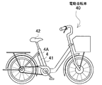
本発明のパック電池は、たとえば、図6に示すように、電動自転車40のモーターを駆動する電源として使用することができる。図に示すパック電池は、電動自転車40のサドル42の下に設けた縦パイプ41の背面に装着している。このように、電動自転車40の縦パイプ41に沿って装着されるパック電池は、幅が広くなると、横方向、あるいは後方に突出し、バランスよく配設できなくなる。とくに、垂直方向に立てた姿勢で、縦パイプ41に沿って安定して装着できなくなる。本発明のパック電池は、電池ブロック集合体10の電池1の配列とリード板5の接続状態を独特の構成とすることにより、多数の電池を所定の出力電圧となるように接続しながら、しかも回路基板6を細長い四角柱状の電池ブロック集合体10の上部に配置して、パック電池全体の横幅を広くすることなくコンパクトにできる。したがって、電動自転車用の電源として、垂直姿勢で立てた姿勢で縦パイプ41に装着するパック電池として、理想的な状態で使用できる。ただ、本発明のパック電池は、電動自転車以外の電動機器の電源として、使用できるのは言うまでもない。とくに、本発明のパック電池は、横幅を広くすることなく、細長い四角柱状としてコンパクトな形状としながら、並列接続する電池の個数を多くして出力電流を大きくすることが求められる用途に好適に使用できる。
The battery pack of the present invention can be used as a power source for driving the motor of the
本発明のパック電池は、屋外で使用される電気機器、とくに、電動自転車や電動オートバイの電源として好適に使用される。 The battery pack of the present invention is suitably used as a power source for electric equipment used outdoors, particularly electric bicycles and electric motorcycles.
1…電池
2…電池ホルダ 2A…ホルダユニット
4…外装ケース 4A…取手
5…リード板 5A…接続部
6…回路基板 6A…貫通孔
7…基板ホルダ
8…リード接続面
9…直列ブロック
10…電池ブロック集合体
11…保持筒 11A…開口部
12…支持側壁
13…挿通穴
14…収納スペース
18…接続窓
19…温度センサー
20…リード板
21…リードピン
22…ボス
23…止ネジ
24…位置決凹部
25…底板
26…周壁
27…支持部
28…連結部
29…連結ボス
30…止ネジ
31…止ネジ
40…電動自転車
41…縦パイプ
42…サドル
90…電池ブロック集合体
91…電池
94…ケース
95…リード板
96…回路基板
DESCRIPTION OF
Claims (4)
この電池ブロック集合体(10)を構成する各々の電池(1)にリード板(5)を介して接続されて、各々の電池電圧を検出する電圧検出回路を備える回路基板(6)と、回路基板(6)を連結てなる電池ブロック集合体(10)を収納している外装ケース(4)とを備えるパック電池であ
って、以下の全ての構成を有するパック電池。
(a)前記電池ブロック集合体(10)は、全体の形状を細長い四角柱状としている。
(b)前記電池ブロック集合体(10)の最も面積の小さい一端面に対向する姿勢で前記回路基板(6)を配置している。
(c)電池ブロック集合体(10)は、複数の直列ブロック(9)を縦方向に多段に積層してい
る。
(d)各々の直列ブロック(9)は、複数の電池(1)を2段の俵積み状に配列している。
(e)2段の俵積み状に配列される直列ブロック(9)は、一方の段の電池(1)の個数を他方の段よりもひとつ少なくしている。
(f)俵積み状に配列される2段の電池(1)は、電池ブロック集合体(10)の縦方向に配置
される。
(g)多段に積層される直列ブロック(9)は、電池(1)の端部電極を、電池ブロック集合体(10)のリード接続面(8)に配置している。
(h)各々の電池(1)は、リード接続面(8)に配置される端部電極にリード板(5)を接続し
ている。
(i)リード板(5)は、電池ブロック集合体(10)の縦方向に長い形状で、直列ブロック(9)を構成する2段の電池(1)を直列に接続し、かつ各々の直列ブロック(9)の電池(1)を並列に接続している。
(j)電池ブロック集合体(10)のリード接続面(8)には、複数枚のリード板(5)を、横に並べて非接触状態に配置している。
(k)各々のリード板(5)の一端を回路基板(6)に接続している。 A battery block assembly (10) in which a plurality of batteries (1) are arranged in a multi-stage multi-row in a parallel posture;
A circuit board (6) having a voltage detection circuit connected to each battery (1) constituting the battery block assembly (10) via a lead plate (5) and detecting each battery voltage, and a circuit A battery pack comprising an outer case (4) housing a battery block assembly (10) formed by connecting substrates (6), and having all the following configurations.
(A) The battery block assembly (10) has an elongated quadrangular prism shape as a whole.
(B) The circuit board (6) is arranged in a posture facing the one end surface having the smallest area of the battery block assembly (10).
(C) The battery block assembly (10) has a plurality of series blocks (9) stacked in multiple stages in the vertical direction.
(D) Each series block (9) has a plurality of batteries (1) arranged in a two-stage stack.
(E) In the series blocks (9) arranged in a two-stage stack, the number of batteries (1) in one stage is one less than that in the other stage.
(F) The two-stage batteries (1) arranged in a stack are arranged in the vertical direction of the battery block assembly (10).
(G) In the series block (9) stacked in multiple stages, the end electrodes of the battery (1) are arranged on the lead connection surface (8) of the battery block assembly (10).
(H) Each battery (1) has a lead plate (5) connected to an end electrode disposed on the lead connection surface (8).
(I) The lead plate (5) has a shape that is long in the vertical direction of the battery block assembly (10), connects the two-stage batteries (1) constituting the series block (9) in series, and each series The battery (1) of the block (9) is connected in parallel.
(J) On the lead connection surface (8) of the battery block assembly (10), a plurality of lead plates (5) are arranged side by side in a non-contact state.
(K) One end of each lead plate (5) is connected to the circuit board (6).
The battery pack according to claim 1, wherein the battery (1) is a lithium ion secondary battery.
Priority Applications (1)
| Application Number | Priority Date | Filing Date | Title |
|---|---|---|---|
| JP2006356921A JP5142521B2 (en) | 2006-12-29 | 2006-12-29 | Pack battery |
Applications Claiming Priority (1)
| Application Number | Priority Date | Filing Date | Title |
|---|---|---|---|
| JP2006356921A JP5142521B2 (en) | 2006-12-29 | 2006-12-29 | Pack battery |
Publications (2)
| Publication Number | Publication Date |
|---|---|
| JP2008166209A JP2008166209A (en) | 2008-07-17 |
| JP5142521B2 true JP5142521B2 (en) | 2013-02-13 |
Family
ID=39695384
Family Applications (1)
| Application Number | Title | Priority Date | Filing Date |
|---|---|---|---|
| JP2006356921A Active JP5142521B2 (en) | 2006-12-29 | 2006-12-29 | Pack battery |
Country Status (1)
| Country | Link |
|---|---|
| JP (1) | JP5142521B2 (en) |
Families Citing this family (10)
| Publication number | Priority date | Publication date | Assignee | Title |
|---|---|---|---|---|
| US8945746B2 (en) | 2009-08-12 | 2015-02-03 | Samsung Sdi Co., Ltd. | Battery pack with improved heat dissipation efficiency |
| JP5410159B2 (en) * | 2009-05-27 | 2014-02-05 | 三洋電機株式会社 | Pack battery |
| JP5813302B2 (en) | 2009-09-07 | 2015-11-17 | 矢崎総業株式会社 | Bus bar module and power supply device including the bus bar module |
| EP2612400B1 (en) | 2010-09-02 | 2014-07-16 | Yazaki Corporation | Busbar module and power supply unit including same busbar module |
| KR101173467B1 (en) | 2011-01-14 | 2012-08-13 | (주)신성이엔지 | Solar cell module assembly |
| CN103026529B (en) * | 2011-05-30 | 2016-08-10 | 松下知识产权经营株式会社 | Battery block and manufacturing method thereof |
| CN102810659B (en) * | 2011-06-01 | 2014-12-31 | 微宏动力系统(湖州)有限公司 | Battery pack of column type batteries |
| JP5704098B2 (en) * | 2012-03-19 | 2015-04-22 | トヨタ自動車株式会社 | Power storage device |
| KR102472233B1 (en) | 2015-11-04 | 2022-11-28 | 삼성에스디아이 주식회사 | Battery module |
| KR20210142939A (en) | 2020-05-19 | 2021-11-26 | 주식회사 엘지에너지솔루션 | Battery Module and Battery Pack Having the Same and Vehicle |
-
2006
- 2006-12-29 JP JP2006356921A patent/JP5142521B2/en active Active
Also Published As
| Publication number | Publication date |
|---|---|
| JP2008166209A (en) | 2008-07-17 |
Similar Documents
| Publication | Publication Date | Title |
|---|---|---|
| JP5178024B2 (en) | Battery pack | |
| CN101527375B (en) | Battery pack | |
| KR100904373B1 (en) | Heat dissipation structure for secondary battery module, and switching board and secondary battery module comprising same | |
| JP5465619B2 (en) | Battery pack | |
| JP5259599B2 (en) | Battery module interface | |
| EP2317585B1 (en) | Battery pack | |
| JP5496746B2 (en) | Battery pack | |
| KR100880389B1 (en) | Manufacturing Method of Secondary Battery Module | |
| JP6049288B2 (en) | Battery pack | |
| JP5546885B2 (en) | Battery pack | |
| JP2011049013A (en) | Battery pack | |
| KR100875606B1 (en) | Secondary battery module | |
| KR20080013040A (en) | Battery pack case | |
| JP5078349B2 (en) | Pack battery | |
| JP4744096B2 (en) | Pack battery | |
| KR102587699B1 (en) | Battery Pack | |
| JP2008251472A (en) | Packed battery | |
| KR102073193B1 (en) | Battery Pack | |
| US8889279B2 (en) | Battery pack | |
| JP5142521B2 (en) | Pack battery | |
| KR100884944B1 (en) | Voltage detection member and battery module including same | |
| JP4761726B2 (en) | Pack battery | |
| AU2017434473B2 (en) | Battery pack | |
| JP2008097942A (en) | Battery pack | |
| KR20140002112A (en) | Battery module |
Legal Events
| Date | Code | Title | Description |
|---|---|---|---|
| A621 | Written request for application examination |
Free format text: JAPANESE INTERMEDIATE CODE: A621 Effective date: 20091127 |
|
| A977 | Report on retrieval |
Free format text: JAPANESE INTERMEDIATE CODE: A971007 Effective date: 20120713 |
|
| A131 | Notification of reasons for refusal |
Free format text: JAPANESE INTERMEDIATE CODE: A131 Effective date: 20120731 |
|
| A521 | Request for written amendment filed |
Free format text: JAPANESE INTERMEDIATE CODE: A523 Effective date: 20120925 |
|
| TRDD | Decision of grant or rejection written | ||
| A01 | Written decision to grant a patent or to grant a registration (utility model) |
Free format text: JAPANESE INTERMEDIATE CODE: A01 Effective date: 20121023 |
|
| A01 | Written decision to grant a patent or to grant a registration (utility model) |
Free format text: JAPANESE INTERMEDIATE CODE: A01 |
|
| A61 | First payment of annual fees (during grant procedure) |
Free format text: JAPANESE INTERMEDIATE CODE: A61 Effective date: 20121120 |
|
| FPAY | Renewal fee payment (event date is renewal date of database) |
Free format text: PAYMENT UNTIL: 20151130 Year of fee payment: 3 |
|
| R151 | Written notification of patent or utility model registration |
Ref document number: 5142521 Country of ref document: JP Free format text: JAPANESE INTERMEDIATE CODE: R151 |
|
| S531 | Written request for registration of change of domicile |
Free format text: JAPANESE INTERMEDIATE CODE: R313531 |
|
| R350 | Written notification of registration of transfer |
Free format text: JAPANESE INTERMEDIATE CODE: R350 |
|
| S111 | Request for change of ownership or part of ownership |
Free format text: JAPANESE INTERMEDIATE CODE: R313111 |
|
| R350 | Written notification of registration of transfer |
Free format text: JAPANESE INTERMEDIATE CODE: R350 |