JP4983257B2 - Exposure apparatus, device manufacturing method, measuring member, and measuring method - Google Patents
Exposure apparatus, device manufacturing method, measuring member, and measuring method Download PDFInfo
- Publication number
- JP4983257B2 JP4983257B2 JP2006531833A JP2006531833A JP4983257B2 JP 4983257 B2 JP4983257 B2 JP 4983257B2 JP 2006531833 A JP2006531833 A JP 2006531833A JP 2006531833 A JP2006531833 A JP 2006531833A JP 4983257 B2 JP4983257 B2 JP 4983257B2
- Authority
- JP
- Japan
- Prior art keywords
- region
- liquid
- exposure apparatus
- pattern
- measurement
- Prior art date
- Legal status (The legal status is an assumption and is not a legal conclusion. Google has not performed a legal analysis and makes no representation as to the accuracy of the status listed.)
- Expired - Fee Related
Links
- 238000000034 method Methods 0.000 title claims description 65
- 238000004519 manufacturing process Methods 0.000 title claims description 16
- 239000007788 liquid Substances 0.000 claims description 700
- 239000000758 substrate Substances 0.000 claims description 262
- 230000003287 optical effect Effects 0.000 claims description 215
- 238000005259 measurement Methods 0.000 claims description 201
- 230000007246 mechanism Effects 0.000 claims description 53
- 239000005871 repellent Substances 0.000 claims description 37
- 230000008569 process Effects 0.000 claims description 36
- 238000012545 processing Methods 0.000 claims description 29
- 230000002940 repellent Effects 0.000 claims description 27
- 238000004378 air conditioning Methods 0.000 claims description 24
- 239000004065 semiconductor Substances 0.000 claims description 10
- VYZAMTAEIAYCRO-UHFFFAOYSA-N Chromium Chemical compound [Cr] VYZAMTAEIAYCRO-UHFFFAOYSA-N 0.000 claims description 6
- 229910052804 chromium Inorganic materials 0.000 claims description 6
- 239000011651 chromium Substances 0.000 claims description 6
- YCKRFDGAMUMZLT-UHFFFAOYSA-N Fluorine atom Chemical compound [F] YCKRFDGAMUMZLT-UHFFFAOYSA-N 0.000 claims description 4
- 229910052731 fluorine Inorganic materials 0.000 claims description 4
- 239000011737 fluorine Substances 0.000 claims description 4
- 229910052782 aluminium Inorganic materials 0.000 claims description 3
- XAGFODPZIPBFFR-UHFFFAOYSA-N aluminium Chemical compound [Al] XAGFODPZIPBFFR-UHFFFAOYSA-N 0.000 claims description 3
- 239000011347 resin Substances 0.000 claims description 3
- 229920005989 resin Polymers 0.000 claims description 3
- 230000001678 irradiating effect Effects 0.000 claims 1
- 238000000691 measurement method Methods 0.000 claims 1
- 238000007654 immersion Methods 0.000 description 62
- 239000010408 film Substances 0.000 description 58
- 238000005286 illumination Methods 0.000 description 33
- 238000011084 recovery Methods 0.000 description 26
- XLYOFNOQVPJJNP-UHFFFAOYSA-N water Substances O XLYOFNOQVPJJNP-UHFFFAOYSA-N 0.000 description 18
- 239000000463 material Substances 0.000 description 17
- 238000010586 diagram Methods 0.000 description 16
- 239000011521 glass Substances 0.000 description 14
- 230000006866 deterioration Effects 0.000 description 12
- 238000001514 detection method Methods 0.000 description 11
- 238000003384 imaging method Methods 0.000 description 9
- 230000010287 polarization Effects 0.000 description 8
- 238000006243 chemical reaction Methods 0.000 description 7
- 230000005484 gravity Effects 0.000 description 7
- 238000004381 surface treatment Methods 0.000 description 7
- 230000004075 alteration Effects 0.000 description 5
- 230000002542 deteriorative effect Effects 0.000 description 5
- 238000005530 etching Methods 0.000 description 5
- 230000002829 reductive effect Effects 0.000 description 5
- 230000015572 biosynthetic process Effects 0.000 description 4
- 230000000694 effects Effects 0.000 description 4
- 229910052751 metal Inorganic materials 0.000 description 4
- 239000002184 metal Substances 0.000 description 4
- 230000009467 reduction Effects 0.000 description 4
- 101000891579 Homo sapiens Microtubule-associated protein tau Proteins 0.000 description 3
- 102100040243 Microtubule-associated protein tau Human genes 0.000 description 3
- 229910004298 SiO 2 Inorganic materials 0.000 description 3
- 230000005540 biological transmission Effects 0.000 description 3
- 230000010363 phase shift Effects 0.000 description 3
- 239000010409 thin film Substances 0.000 description 3
- 238000002834 transmittance Methods 0.000 description 3
- 230000007423 decrease Effects 0.000 description 2
- 230000004907 flux Effects 0.000 description 2
- 238000005339 levitation Methods 0.000 description 2
- 239000004973 liquid crystal related substance Substances 0.000 description 2
- 239000003921 oil Substances 0.000 description 2
- 230000000737 periodic effect Effects 0.000 description 2
- 238000000206 photolithography Methods 0.000 description 2
- 229920002120 photoresistant polymer Polymers 0.000 description 2
- 230000000750 progressive effect Effects 0.000 description 2
- 210000001747 pupil Anatomy 0.000 description 2
- 239000010453 quartz Substances 0.000 description 2
- 238000005488 sandblasting Methods 0.000 description 2
- VYPSYNLAJGMNEJ-UHFFFAOYSA-N silicon dioxide Inorganic materials O=[Si]=O VYPSYNLAJGMNEJ-UHFFFAOYSA-N 0.000 description 2
- 239000000126 substance Substances 0.000 description 2
- 241000218645 Cedrus Species 0.000 description 1
- 206010010071 Coma Diseases 0.000 description 1
- 206010067482 No adverse event Diseases 0.000 description 1
- 239000004721 Polyphenylene oxide Substances 0.000 description 1
- XUIMIQQOPSSXEZ-UHFFFAOYSA-N Silicon Chemical compound [Si] XUIMIQQOPSSXEZ-UHFFFAOYSA-N 0.000 description 1
- 230000008901 benefit Effects 0.000 description 1
- 239000000919 ceramic Substances 0.000 description 1
- 230000003749 cleanliness Effects 0.000 description 1
- 239000011248 coating agent Substances 0.000 description 1
- 238000000576 coating method Methods 0.000 description 1
- 239000000470 constituent Substances 0.000 description 1
- 239000006059 cover glass Substances 0.000 description 1
- 238000013461 design Methods 0.000 description 1
- 238000007599 discharging Methods 0.000 description 1
- 238000009826 distribution Methods 0.000 description 1
- 239000012530 fluid Substances 0.000 description 1
- 229910052736 halogen Inorganic materials 0.000 description 1
- 150000002367 halogens Chemical class 0.000 description 1
- 230000006872 improvement Effects 0.000 description 1
- 239000012535 impurity Substances 0.000 description 1
- 238000007689 inspection Methods 0.000 description 1
- 230000010354 integration Effects 0.000 description 1
- 238000001459 lithography Methods 0.000 description 1
- 239000012528 membrane Substances 0.000 description 1
- QSHDDOUJBYECFT-UHFFFAOYSA-N mercury Chemical compound [Hg] QSHDDOUJBYECFT-UHFFFAOYSA-N 0.000 description 1
- 229910052753 mercury Inorganic materials 0.000 description 1
- 239000000203 mixture Substances 0.000 description 1
- 230000004048 modification Effects 0.000 description 1
- 238000012986 modification Methods 0.000 description 1
- 231100000989 no adverse effect Toxicity 0.000 description 1
- 239000003960 organic solvent Substances 0.000 description 1
- 238000012858 packaging process Methods 0.000 description 1
- 230000002093 peripheral effect Effects 0.000 description 1
- 229920000570 polyether Polymers 0.000 description 1
- 230000000717 retained effect Effects 0.000 description 1
- 230000002441 reversible effect Effects 0.000 description 1
- 238000007788 roughening Methods 0.000 description 1
- 238000004904 shortening Methods 0.000 description 1
- 229910052710 silicon Inorganic materials 0.000 description 1
- 239000010703 silicon Substances 0.000 description 1
- 230000001360 synchronised effect Effects 0.000 description 1
- 230000036962 time dependent Effects 0.000 description 1
- 238000013519 translation Methods 0.000 description 1
- 229910021642 ultra pure water Inorganic materials 0.000 description 1
- 239000012498 ultrapure water Substances 0.000 description 1
- 230000000007 visual effect Effects 0.000 description 1
Images


Classifications
-
- G—PHYSICS
- G03—PHOTOGRAPHY; CINEMATOGRAPHY; ANALOGOUS TECHNIQUES USING WAVES OTHER THAN OPTICAL WAVES; ELECTROGRAPHY; HOLOGRAPHY
- G03F—PHOTOMECHANICAL PRODUCTION OF TEXTURED OR PATTERNED SURFACES, e.g. FOR PRINTING, FOR PROCESSING OF SEMICONDUCTOR DEVICES; MATERIALS THEREFOR; ORIGINALS THEREFOR; APPARATUS SPECIALLY ADAPTED THEREFOR
- G03F7/00—Photomechanical, e.g. photolithographic, production of textured or patterned surfaces, e.g. printing surfaces; Materials therefor, e.g. comprising photoresists; Apparatus specially adapted therefor
- G03F7/70—Microphotolithographic exposure; Apparatus therefor
- G03F7/708—Construction of apparatus, e.g. environment aspects, hygiene aspects or materials
- G03F7/7085—Detection arrangement, e.g. detectors of apparatus alignment possibly mounted on wafers, exposure dose, photo-cleaning flux, stray light, thermal load
-
- G—PHYSICS
- G03—PHOTOGRAPHY; CINEMATOGRAPHY; ANALOGOUS TECHNIQUES USING WAVES OTHER THAN OPTICAL WAVES; ELECTROGRAPHY; HOLOGRAPHY
- G03F—PHOTOMECHANICAL PRODUCTION OF TEXTURED OR PATTERNED SURFACES, e.g. FOR PRINTING, FOR PROCESSING OF SEMICONDUCTOR DEVICES; MATERIALS THEREFOR; ORIGINALS THEREFOR; APPARATUS SPECIALLY ADAPTED THEREFOR
- G03F7/00—Photomechanical, e.g. photolithographic, production of textured or patterned surfaces, e.g. printing surfaces; Materials therefor, e.g. comprising photoresists; Apparatus specially adapted therefor
- G03F7/70—Microphotolithographic exposure; Apparatus therefor
- G03F7/70216—Mask projection systems
- G03F7/70341—Details of immersion lithography aspects, e.g. exposure media or control of immersion liquid supply
-
- G—PHYSICS
- G03—PHOTOGRAPHY; CINEMATOGRAPHY; ANALOGOUS TECHNIQUES USING WAVES OTHER THAN OPTICAL WAVES; ELECTROGRAPHY; HOLOGRAPHY
- G03F—PHOTOMECHANICAL PRODUCTION OF TEXTURED OR PATTERNED SURFACES, e.g. FOR PRINTING, FOR PROCESSING OF SEMICONDUCTOR DEVICES; MATERIALS THEREFOR; ORIGINALS THEREFOR; APPARATUS SPECIALLY ADAPTED THEREFOR
- G03F7/00—Photomechanical, e.g. photolithographic, production of textured or patterned surfaces, e.g. printing surfaces; Materials therefor, e.g. comprising photoresists; Apparatus specially adapted therefor
- G03F7/20—Exposure; Apparatus therefor
- G03F7/2041—Exposure; Apparatus therefor in the presence of a fluid, e.g. immersion; using fluid cooling means
-
- G—PHYSICS
- G03—PHOTOGRAPHY; CINEMATOGRAPHY; ANALOGOUS TECHNIQUES USING WAVES OTHER THAN OPTICAL WAVES; ELECTROGRAPHY; HOLOGRAPHY
- G03F—PHOTOMECHANICAL PRODUCTION OF TEXTURED OR PATTERNED SURFACES, e.g. FOR PRINTING, FOR PROCESSING OF SEMICONDUCTOR DEVICES; MATERIALS THEREFOR; ORIGINALS THEREFOR; APPARATUS SPECIALLY ADAPTED THEREFOR
- G03F7/00—Photomechanical, e.g. photolithographic, production of textured or patterned surfaces, e.g. printing surfaces; Materials therefor, e.g. comprising photoresists; Apparatus specially adapted therefor
- G03F7/70—Microphotolithographic exposure; Apparatus therefor
- G03F7/708—Construction of apparatus, e.g. environment aspects, hygiene aspects or materials
- G03F7/70908—Hygiene, e.g. preventing apparatus pollution, mitigating effect of pollution or removing pollutants from apparatus
- G03F7/70916—Pollution mitigation, i.e. mitigating effect of contamination or debris, e.g. foil traps
Landscapes
- Physics & Mathematics (AREA)
- General Physics & Mathematics (AREA)
- Health & Medical Sciences (AREA)
- Epidemiology (AREA)
- Public Health (AREA)
- Engineering & Computer Science (AREA)
- Environmental & Geological Engineering (AREA)
- Life Sciences & Earth Sciences (AREA)
- Atmospheric Sciences (AREA)
- Exposure And Positioning Against Photoresist Photosensitive Materials (AREA)
- Exposure Of Semiconductors, Excluding Electron Or Ion Beam Exposure (AREA)
Description
本発明は、液体を介して基板を露光する露光装置、及びその露光装置を用いるデバイス製造方法に関するものである。
本願は、2004年8月18日に出願された特願2004−238007号、2004年10月25日に出願された特願2004−309322号、及び2005年3月28日に出願された特願2005−091221号に基づき優先権を主張し、その内容をここに援用する。The present invention relates to an exposure apparatus that exposes a substrate through a liquid and a device manufacturing method that uses the exposure apparatus.
The present application includes Japanese Patent Application No. 2004-238007 filed on August 18, 2004, Japanese Patent Application No. 2004-309322 filed on October 25, 2004, and Japanese Patent Application filed on March 28, 2005. Claims priority based on 2005-0912121, the contents of which are incorporated herein.
半導体デバイスや液晶表示デバイスは、マスク上に形成されたパターンを感光性の基板上に転写する、いわゆるフォトリソグラフィの手法により製造される。このフォトリソグラフィ工程で使用される露光装置は、マスクを支持するマスクステージと基板を支持する基板ステージとを有し、マスクステージ及び基板ステージを逐次移動しながらマスクのパターンを投影光学系を介して基板に転写するものである。近年、デバイスパターンのより一層の高集積化に対応するために投影光学系の更なる高解像度化が望まれている。投影光学系の解像度は、使用する露光波長が短いほど、また投影光学系の開口数が大きいほど高くなる。そのため、露光装置で使用される露光波長は年々短波長化しており、投影光学系の開口数も増大している。そして、現在主流の露光波長はKrFエキシマレーザの248nmであるが、更に短波長のArFエキシマレーザの193nmも実用化されつつある。また、露光を行う際には、解像度と同様に焦点深度(DOF)も重要となる。解像度R、及び焦点深度δはそれぞれ以下の式で表される。
R=k1・λ/NA ... (1)
δ=±k2・λ/NA2 ... (2)
ここで、λは露光波長、NAは投影光学系の開口数、k1、k2はプロセス係数である。(1)式、(2)式より、解像度Rを高めるために、露光波長λを短くして、開口数NAを大きくすると、焦点深度δが狭くなることが分かる。Semiconductor devices and liquid crystal display devices are manufactured by a so-called photolithography technique in which a pattern formed on a mask is transferred onto a photosensitive substrate. An exposure apparatus used in this photolithography process has a mask stage for supporting a mask and a substrate stage for supporting a substrate, and a mask pattern is transferred via a projection optical system while sequentially moving the mask stage and the substrate stage. It is transferred to the substrate. In recent years, in order to cope with higher integration of device patterns, higher resolution of the projection optical system is desired. The resolution of the projection optical system becomes higher as the exposure wavelength used is shorter and the numerical aperture of the projection optical system is larger. Therefore, the exposure wavelength used in the exposure apparatus is shortened year by year, and the numerical aperture of the projection optical system is also increasing. The mainstream exposure wavelength is 248 nm of the KrF excimer laser, but the 193 nm of the shorter wavelength ArF excimer laser is also being put into practical use. Also, when performing exposure, the depth of focus (DOF) is important as well as the resolution. The resolution R and the depth of focus δ are each expressed by the following equations.
R = k 1 · λ / NA (1)
δ = ± k 2 · λ / NA 2 (2)
Here, λ is the exposure wavelength, NA is the numerical aperture of the projection optical system, and k 1 and k 2 are process coefficients. From the equations (1) and (2), it can be seen that the depth of focus δ becomes narrower when the exposure wavelength λ is shortened and the numerical aperture NA is increased in order to increase the resolution R.
焦点深度δが狭くなり過ぎると、投影光学系の像面に対して基板表面を合致させることが困難となり、露光動作時のフォーカスマージンが不足するおそれがある。そこで、実質的に露光波長を短くして、且つ焦点深度を広くする方法として、例えば下記特許文献1に開示されている液浸法が提案されている。この液浸法は、投影光学系の下面と基板表面との間を水や有機溶媒等の液体で満たして液浸領域を形成し、液体中での露光光の波長が空気中の1/n(nは液体の屈折率で通常1.2〜1.6程度)になることを利用して解像度を向上するとともに、焦点深度を約n倍に拡大するというものである。
ところで、基板ステージ上には投影光学系を介した光を計測する種々の計測部が設けられているが、液浸露光装置の場合、投影光学系と計測部との間に液体を満たして計測部上に液浸領域を形成し、その液浸領域の液体を介して光を計測することが考えられる。その場合において、例えば計測部上の液体の除去動作を行った後、計測部上に液体が残留していると、その残留した液体が気化した後に計測部上に液体の付着跡(以下、液体が純水でない場合も「ウォーターマーク」と称する)を形成するおそれがある。ウォーターマークは異物として作用するため、その計測部を有する計測システムの計測精度の劣化を招くおそれが生じる。 By the way, various measurement units that measure light via the projection optical system are provided on the substrate stage. In the case of an immersion exposure apparatus, measurement is performed by filling a liquid between the projection optical system and the measurement unit. It is conceivable to form an immersion area on the part and measure light through the liquid in the immersion area. In that case, for example, after the liquid removal operation on the measurement unit is performed, if the liquid remains on the measurement unit, the liquid adhesion trace (hereinafter referred to as liquid) May be formed as “watermark” even when the water is not pure water. Since the watermark acts as a foreign substance, the measurement accuracy of the measurement system having the measurement unit may be deteriorated.
本発明はこのような事情に鑑みてなされたものであって、計測部上に液浸領域を形成して高精度な計測を実行できる露光装置、およびその露光装置を用いるデバイス製造方法を提供することを目的とする。
また、計測部上に液体が残留することを防止できる露光装置、及びその露光装置を用いるデバイス製造方法を提供することを目的とする。The present invention has been made in view of such circumstances, and provides an exposure apparatus that can form a liquid immersion region on a measurement unit and perform highly accurate measurement, and a device manufacturing method using the exposure apparatus. For the purpose.
It is another object of the present invention to provide an exposure apparatus that can prevent liquid from remaining on the measurement unit and a device manufacturing method that uses the exposure apparatus.
上記の課題を解決するため、本発明は実施の形態に示す各図に対応付けした以下の構成を採用している。但し、各要素に付した括弧付き符号はその要素の例示に過ぎず、各要素を限定するものではない。 In order to solve the above-described problems, the present invention employs the following configurations corresponding to the respective drawings shown in the embodiments. However, the reference numerals with parentheses attached to each element are merely examples of the element and do not limit each element.
本発明の第1の態様に従えば、液体(LQ)を介して基板(P)を露光する露光装置において、所定面(51、65A)上に形成された第1パターン(61)を有する計測システム(60)と、所定面(51、65A)上において第1パターン(61)を含む第1領域(S1)の近傍に規定された第2領域(S2)とを備え、第2領域(S2)には、第1領域(S1)と第2領域(S2)とにまたがるようにして残留した液体(LQ)が、第1領域(S1)より退いて第2領域(S2)に集まるように第2パターン(80)が形成されている露光装置(EX)が提供される。 According to the first aspect of the present invention, in the exposure apparatus that exposes the substrate (P) through the liquid (LQ), the measurement having the first pattern (61) formed on the predetermined surface (51, 65A). The system (60) includes a second region (S2) defined in the vicinity of the first region (S1) including the first pattern (61) on the predetermined surface (51, 65A). ) So that the liquid (LQ) remaining so as to straddle the first region (S1) and the second region (S2) retreats from the first region (S1) and collects in the second region (S2). An exposure apparatus (EX) in which the second pattern (80) is formed is provided.
本発明の第1の態様によれば、計測システムの第1パターンを含む第1領域とその近傍に規定された第2領域とにまたがるようにして液体が残留した場合において、第2領域に形成されている第2パターンによって、液体は第1領域より退いて第2領域に集まる。したがって、第1パターンを含む第1領域上に液体が残留することを防止できる。したがって、計測システムの第1パターン上にウォーターマークが形成されることを防止でき、残留した液体やウォーターマークに起因する計測システムの計測精度の劣化を防止できる。 According to the first aspect of the present invention, the liquid is formed in the second region when the liquid remains so as to extend over the first region including the first pattern of the measurement system and the second region defined in the vicinity thereof. By the second pattern, the liquid retreats from the first region and collects in the second region. Therefore, it is possible to prevent the liquid from remaining on the first region including the first pattern. Therefore, it is possible to prevent the watermark from being formed on the first pattern of the measurement system, and it is possible to prevent the measurement accuracy of the measurement system from being deteriorated due to the remaining liquid or the watermark.
本発明の第2の態様に従えば、液体(LQ)を介して基板(P)を露光する露光装置において、所定面(51、65A)上に計測部(61)が配置された計測システム(60)と、所定面(51、65A)上において計測部(61)を含むように規定された第1領域(S1)と、所定面(51、65A)上において第1領域(S1)の近傍に規定された第2領域(S2)とを備え、第1領域(S1)と第2領域(S2)とにまたがるようにして残留した液体(LQ)が、第1領域(S1)より退いて第2領域(S2)に集まるように、第1領域(S1)の表面と第2領域(S2)の表面との少なくとも一方に所定の加工が施されている露光装置(EX)が提供される。 According to the second aspect of the present invention, in the exposure apparatus that exposes the substrate (P) through the liquid (LQ), the measurement system (61, 61) is disposed on the predetermined surface (51, 65A) ( 60), the first area (S1) defined to include the measurement unit (61) on the predetermined surface (51, 65A), and the vicinity of the first area (S1) on the predetermined surface (51, 65A) The liquid (LQ) remaining so as to straddle the first region (S1) and the second region (S2) is retreated from the first region (S1). An exposure apparatus (EX) is provided in which predetermined processing is performed on at least one of the surface of the first region (S1) and the surface of the second region (S2) so as to gather in the second region (S2). .
本発明の第2の態様によれば、計測部を含むように規定された第1領域とその近傍に規定された第2領域との少なくとも一方に所定の加工が施されているので、その第1の領域と第2の領域とにまたがるようにして液体が残留した場合において、液体は第1領域より退いて第2領域に集まる。したがって、計測部を含む第1領域上に液体が残留することを防止できる。したがって、計測システムの計測部上にウォーターマークが形成されることを防止でき、残留した液体やウォーターマークに起因する計測システムの計測精度の劣化を防止できる。 According to the second aspect of the present invention, since predetermined processing is applied to at least one of the first region defined to include the measurement unit and the second region defined in the vicinity thereof, When the liquid remains so as to straddle the first region and the second region, the liquid retreats from the first region and collects in the second region. Therefore, it is possible to prevent the liquid from remaining on the first region including the measurement unit. Therefore, it is possible to prevent the watermark from being formed on the measurement unit of the measurement system, and it is possible to prevent the measurement accuracy of the measurement system from deteriorating due to the remaining liquid or the watermark.
本発明の第3の態様に従えば、液体(LQ)を介して基板(P)を露光する露光装置において、所定面(51、65A)上に計測部(61)が配置された計測システム(60)と、その所定面(51、65A)上において、計測部(61)を含むように規定された第1領域(S1)と、その所定面(51、65A)上において、第1領域(S1)を含むように、第1領域(S1)よりも大きく規定された第2領域(S2、W1)とを備え、第1領域(S1)と第2領域(S2、W1)とにまたがるようにして残留した液体(LQ)が、第1領域(S1)より退いて第2領域(S2、W1)に集まるように、第1領域(S1)は第2領域(S2、W1)の中心(G'')から外れた位置に規定されている露光装置(EX)が提供される。 According to the third aspect of the present invention, in the exposure apparatus that exposes the substrate (P) through the liquid (LQ), the measurement system (61, 61) is disposed on the predetermined surface (51, 65A). 60), a first area (S1) defined to include the measurement unit (61) on the predetermined plane (51, 65A), and a first area (51, 65A) on the predetermined plane (51, 65A). S1) includes a second region (S2, W1) that is defined larger than the first region (S1), and spans the first region (S1) and the second region (S2, W1). Thus, the first region (S1) is centered on the second region (S2, W1) so that the liquid (LQ) remaining in this manner moves away from the first region (S1) and collects in the second region (S2, W1). An exposure apparatus (EX) defined at a position deviating from G ″) is provided.
本発明の第3の態様によれば、液体が第1領域と第2領域とにまたがるように残留しても、液体は第1領域から退いて第2領域に集まるため、計測部を含む第1領域での液体の残留を防止できる。したがって、計測システムの計測部上にウォーターマークが形成されることを防止でき、計測システムの計測精度の劣化を防止できる。 According to the third aspect of the present invention, even if the liquid remains so as to straddle the first region and the second region, the liquid retreats from the first region and collects in the second region. It is possible to prevent liquid from remaining in one region. Therefore, it is possible to prevent a watermark from being formed on the measurement unit of the measurement system, and it is possible to prevent deterioration in measurement accuracy of the measurement system.
本発明の第4の態様に従えば、液体(LQ)を介して基板(P)を露光する露光装置において、所定面(51、65A)上に計測部(61)が配置された計測システム(60)と、所定面(51、65A)上において計測部(61)を含むように規定された第1領域(S1)とを備え、第1領域(S1)に残留した液体(LQ)が、第1領域(S1)より退くように、第1領域(S1)は傾斜している露光装置(EX)が提供される。 According to the fourth aspect of the present invention, in the exposure apparatus that exposes the substrate (P) through the liquid (LQ), the measurement system (61) is disposed on the predetermined surface (51, 65A) ( 60) and a first region (S1) defined to include the measurement unit (61) on the predetermined surface (51, 65A), and the liquid (LQ) remaining in the first region (S1) is An exposure apparatus (EX) is provided in which the first region (S1) is inclined so as to recede from the first region (S1).
本発明の第4の態様によれば、計測部を含むように規定された第1領域を傾斜させることで、第1の領域上に液体が残留した場合でも、その残留した液体を第1領域より退かすことができる。したがって、計測部を含む第1領域上に液体が残留することを防止できる。したがって、計測システムの計測部上にウォーターマークが形成されることを防止でき、残留した液体やウォーターマークに起因する計測システムの計測精度の劣化を防止できる。 According to the fourth aspect of the present invention, even if liquid remains on the first region by inclining the first region defined to include the measurement unit, the remaining liquid is removed from the first region. Can be dismissed more. Therefore, it is possible to prevent the liquid from remaining on the first region including the measurement unit. Therefore, it is possible to prevent the watermark from being formed on the measurement unit of the measurement system, and it is possible to prevent the measurement accuracy of the measurement system from deteriorating due to the remaining liquid or the watermark.
本発明の第5の態様に従えば、液体(LQ)を介して基板(P)を露光する露光装置において、所定面(51、65A)上に計測部(61)が配置された計測システム(60)と、所定面(51、65A)上において計測部(61)を含むように規定された第1領域(S1)とを備え、第1領域(S1)に残留した液体(LQ)が、第1領域(S1)より退くように、第1領域(S1)上に気体の流れを生成する露光装置(EX)が提供される。 According to the fifth aspect of the present invention, in the exposure apparatus that exposes the substrate (P) through the liquid (LQ), the measurement system (61, 61) is disposed on the predetermined surface (51, 65A). 60) and a first region (S1) defined to include the measurement unit (61) on the predetermined surface (51, 65A), and the liquid (LQ) remaining in the first region (S1) is An exposure apparatus (EX) that generates a gas flow on the first area (S1) is provided so as to retreat from the first area (S1).
本発明の第5の態様によれば、計測部を含むように規定された第1領域上に気体の流れを生成することで、その残留した液体を第1領域より退かすことができる。したがって、計測部を含む第1領域上に液体が残留することを防止できる。したがって、計測システムの計測部上にウォーターマークが形成されることを防止でき、残留した液体やウォーターマークに起因する計測システムの計測精度の劣化を防止できる。
本発明の第6の態様に従えば、液体(LQ)を介して基板(P)を露光する露光装置において、所定面(51、65A)上に計測部(61)が配置された計測システム(60)と、所定面(51、65A)上で計測部(61)を含むように規定された第1領域(W1)と、第1領域(W2)近傍の第2領域(W2)とを備え、第2領域(W2)の表面には撥液性の膜が形成され、第1領域(W1)の表面には撥液性の膜が形成されていない露光装置(EX)が提供される。
本発明の第6の態様によれば、計測部上に撥液性の膜が形成されていないので、撥液性の膜の劣化に起因する計測精度の低下を防止することができる。According to the fifth aspect of the present invention, the remaining liquid can be retreated from the first region by generating a gas flow on the first region defined to include the measurement unit. Therefore, it is possible to prevent the liquid from remaining on the first region including the measurement unit. Therefore, it is possible to prevent the watermark from being formed on the measurement unit of the measurement system, and it is possible to prevent the measurement accuracy of the measurement system from deteriorating due to the remaining liquid or the watermark.
According to the sixth aspect of the present invention, in the exposure apparatus that exposes the substrate (P) through the liquid (LQ), the measurement system (61, 61) is disposed on the predetermined surface (51, 65A). 60), a first region (W1) defined to include the measurement unit (61) on the predetermined surface (51, 65A), and a second region (W2) in the vicinity of the first region (W2). An exposure apparatus (EX) is provided in which a liquid-repellent film is formed on the surface of the second region (W2) and no liquid-repellent film is formed on the surface of the first region (W1).
According to the sixth aspect of the present invention, since the liquid repellent film is not formed on the measurement unit, it is possible to prevent a decrease in measurement accuracy due to the deterioration of the liquid repellent film.
本発明の第7の態様に従えば、上記態様の露光装置(EX)を用いるデバイス製造方法が提供される。 According to the seventh aspect of the present invention, there is provided a device manufacturing method using the exposure apparatus (EX) of the above aspect.
本発明の第7の態様によれば、計測システムの計測精度の劣化を防止した状態で計測処理を行うことができるので、その計測結果に基づいて、デバイスを製造するための露光処理を良好に行うことができる。したがって、所望の性能を有するデバイスを提供することができる。 According to the seventh aspect of the present invention, since the measurement process can be performed in a state in which the measurement accuracy of the measurement system is prevented from being deteriorated, the exposure process for manufacturing the device is favorably performed based on the measurement result. It can be carried out. Therefore, a device having desired performance can be provided.
本発明によれば、計測システムの計測精度の劣化を防止し、良好な計測精度を維持した状態で基板を露光することができる。 According to the present invention, it is possible to prevent the measurement accuracy of the measurement system from being deteriorated and to expose the substrate while maintaining good measurement accuracy.
1...液浸機構、51...上面、60...空間像計測システム、61...第1パターン、65...スリット板、65A...上面、73...受光素子、80...第2パターン、80F...ドット状パターン、80G...格子状パターン、81...ラインパターン、470...ピンホール部、700...気体供給系、701A...気体供給口、800...空調系、825...空調空間、EX...露光装置、LQ...液体、P...基板、PL...投影光学系、PST...基板ステージ、S1...第1領域、S2...第2領域、W1...親液性領域、W2...撥液性領域
DESCRIPTION OF
以下、本発明に係る露光装置の実施形態について図面を参照しながら説明する。 Embodiments of an exposure apparatus according to the present invention will be described below with reference to the drawings.
<第1の実施形態>
図1は第1の実施形態に係る露光装置EXを示す概略構成図である。図1において、露光装置EXは、マスクMを支持して移動可能なマスクステージMSTと、基板Pを保持する基板ホルダPHを有し、基板ホルダPHに基板Pを保持して移動可能な基板ステージPSTと、マスクステージMSTに支持されているマスクMを露光光ELで照明する照明光学系ILと、露光光ELで照明されたマスクMのパターンの像を基板ステージPSTに支持されている基板Pに投影する投影光学系PLと、露光装置EX全体の動作を統括制御する制御装置CONTとを備えている。更に露光装置EXは、投影光学系PLの結像特性(光学特性)の計測に用いられる空間像計測システム60を備えている。空間像計測システム60は、投影光学系PLの像面側に配置されたスリット部61を有するスリット板65と、光電変換素子からなる受光素子73と、スリット板65を通過した光を受光素子73に導く光学系74とを備えている。受光素子73は、スリット板65及び光学系74を介して投影光学系PLを通過した光(露光光EL)を受光する。<First Embodiment>
FIG. 1 is a schematic block diagram that shows an exposure apparatus EX according to the first embodiment. In FIG. 1, an exposure apparatus EX includes a mask stage MST that can move while supporting a mask M, and a substrate holder PH that holds a substrate P, and a substrate stage that can move while holding the substrate P in the substrate holder PH. PST, illumination optical system IL for illuminating mask M supported on mask stage MST with exposure light EL, and substrate P supported on substrate stage PST for an image of the pattern of mask M illuminated with exposure light EL A projection optical system PL for projecting onto the projector and a control device CONT for overall control of the overall operation of the exposure apparatus EX. Further, the exposure apparatus EX includes an aerial
本実施形態の露光装置EXは、露光波長を実質的に短くして解像度を向上するとともに焦点深度を実質的に広くするために液浸法を適用した液浸露光装置であって、投影光学系PLの像面側に液体LQの液浸領域AR2を形成する液浸機構1を備えている。液浸機構1は、投影光学系PLの像面側に液体LQを供給する液体供給機構10と、投影光学系PLの像面側の液体LQを回収する液体回収機構20とを備えている。本実施形態において、液体LQとして純水が用いられる。露光装置EXは、少なくともマスクMのパターン像を基板P上に投影している間、液体供給機構10から供給した液体LQにより投影光学系PLの投影領域AR1を含む基板P上の少なくとも一部に、投影領域AR1よりも大きく且つ基板Pよりも小さい液浸領域AR2を局所的に形成する。具体的には、露光装置EXは、投影光学系PLの像面側先端の光学素子2と基板Pの表面(露光面)との間を液体LQで満たして液浸領域AR2を形成し、この投影光学系PLと基板Pとの間の液体LQ及び投影光学系PLを介してマスクMのパターン像を基板P上に投影することによって、基板Pを露光する。
The exposure apparatus EX of the present embodiment is an immersion exposure apparatus to which an immersion method is applied in order to substantially shorten the exposure wavelength to improve the resolution and substantially widen the depth of focus. An
また、投影光学系PLの像面側近傍、具体的には投影光学系PLの像面側先端の光学素子2の近傍には、液浸機構1の一部を構成するノズル部材70が配置されている。ノズル部材70は、基板P(基板ステージPST)の上方において投影光学系PLの先端の周りを囲むように設けられた環状部材である。
Further, a
ここで、本実施形態では、露光装置EXとしてマスクMと基板Pとを走査方向(所定方向)における互いに異なる向き(逆方向)に同期移動しつつマスクMに形成されたパターンで基板Pを露光する走査型露光装置(所謂スキャニングステッパ)を使用する場合を例にして説明する。以下の説明において、水平面内においてマスクMと基板Pとの同期移動方向(走査方向、所定方向)をX軸方向、水平面内においてX軸方向と直交する方向をY軸方向(非走査方向)、X軸及びY軸方向に垂直で投影光学系PLの光軸AXと一致する方向をZ軸方向とする。また、X軸、Y軸、及びZ軸まわりの回転(傾斜)方向をそれぞれ、θX、θY、及びθZ方向とする。なお、ここでいう「基板」は半導体ウエハ上にレジストを塗布したものを含み、「マスク」は基板上に縮小投影されるデバイスパターンを形成されたレチクルを含む。 In this embodiment, the exposure apparatus EX exposes the substrate P with a pattern formed on the mask M while synchronously moving the mask M and the substrate P in mutually different directions (reverse directions) in the scanning direction (predetermined direction). An example of using a scanning exposure apparatus (so-called scanning stepper) will be described. In the following description, the synchronous movement direction (scanning direction, predetermined direction) of the mask M and the substrate P in the horizontal plane is the X axis direction, and the direction orthogonal to the X axis direction is the Y axis direction (non-scanning direction) in the horizontal plane. A direction perpendicular to the X-axis and Y-axis directions and coincident with the optical axis AX of the projection optical system PL is defined as a Z-axis direction. Further, the rotation (inclination) directions around the X axis, Y axis, and Z axis are the θX, θY, and θZ directions, respectively. Here, the “substrate” includes a semiconductor wafer coated with a resist, and the “mask” includes a reticle on which a device pattern to be reduced and projected on the substrate is formed.
照明光学系ILは、マスクステージMSTに支持されているマスクMを露光光ELで照明するものであり、露光用光源、露光用光源から射出された光束の照度を均一化するオプティカルインテグレータ、オプティカルインテグレータからの露光光ELを集光するコンデンサレンズ、リレーレンズ系、露光光ELによるマスクM上の照明領域を設定する視野絞り等を有している。マスクM上の所定の照明領域は照明光学系ILにより均一な照度分布の露光光ELで照明される。照明光学系ILから射出される露光光ELとしては、例えば水銀ランプから射出される紫外域の輝線(g線、h線、i線)及びKrFエキシマレーザ光(波長248nm)等の遠紫外光(DUV光)や、ArFエキシマレーザ光(波長193nm)及びF2レーザ光(波長157nm)等の真空紫外光(VUV光)などが用いられる。本実施形態では、ArFエキシマレーザ光が用いられる。上述したように、本実施形態における液体LQは純水であって、露光光ELがArFエキシマレーザ光であっても透過可能である。また、純水は紫外域の輝線(g線、h線、i線)及びKrFエキシマレーザ光(波長248nm)等の遠紫外光(DUV光)も透過可能である。The illumination optical system IL illuminates the mask M supported by the mask stage MST with the exposure light EL, and the exposure light source, and an optical integrator and an optical integrator for uniformizing the illuminance of the light beam emitted from the exposure light source A condenser lens that collects the exposure light EL from the lens, a relay lens system, a field stop for setting an illumination area on the mask M by the exposure light EL, and the like. A predetermined illumination area on the mask M is illuminated with the exposure light EL having a uniform illuminance distribution by the illumination optical system IL. As the exposure light EL emitted from the illumination optical system IL, for example, far ultraviolet light (g-line, h-line, i-line) and KrF excimer laser light (wavelength 248 nm) emitted from a mercury lamp, DUV light), vacuum ultraviolet light (VUV light) such as ArF excimer laser light (wavelength 193 nm) and F 2 laser light (wavelength 157 nm), or the like is used. In this embodiment, ArF excimer laser light is used. As described above, the liquid LQ in the present embodiment is pure water and can be transmitted even if the exposure light EL is ArF excimer laser light. Further, pure water can transmit ultraviolet rays (g-rays, h-rays, i-rays) and far-ultraviolet light (DUV light) such as KrF excimer laser light (wavelength 248 nm).
マスクステージMSTは、マスクMを保持して移動可能であって、投影光学系PLの光軸AXに垂直な平面内、すなわちXY平面内で2次元移動可能及びθZ方向に微小回転可能である。マスクステージMSTはリニアモータ等を含むマスクステージ駆動機構MSTDにより駆動される。マスクステージ駆動機構MSTDは制御装置CONTにより制御される。マスクステージMST上には移動鏡41が設けられている。また、移動鏡41に対向する位置にはレーザ干渉計42が設けられている。マスクステージMST上のマスクMの2次元方向の位置、及び回転角はレーザ干渉計42によりリアルタイムで計測され、計測結果は制御装置CONTに出力される。制御装置CONTはレーザ干渉計42の計測結果に基づいてマスクステージ駆動機構MSTDを駆動することでマスクステージMSTに支持されているマスクMの位置決めを行う。
The mask stage MST can move while holding the mask M, can move two-dimensionally in a plane perpendicular to the optical axis AX of the projection optical system PL, that is, in the XY plane, and can be rotated slightly in the θZ direction. Mask stage MST is driven by a mask stage drive mechanism MSTD including a linear motor and the like. The mask stage drive mechanism MSTD is controlled by the control device CONT. A movable mirror 41 is provided on the mask stage MST. A
投影光学系PLは、マスクMのパターンの像を所定の投影倍率βで基板Pに投影するものであって、投影光学系PLの像面側の先端に設けられた光学素子2を含む複数の光学素子で構成されており、これら光学素子は鏡筒PKで支持されている。本実施形態において、投影光学系PLは、投影倍率βが例えば1/4、1/5、あるいは1/8の縮小系である。なお、投影光学系PLは等倍系及び拡大系のいずれでもよい。また、投影光学系PLは、反射素子を含まない屈折系、屈折素子を含まない反射系、屈折素子と反射素子とを含む反射屈折系のいずれであってもよい。また、本実施形態の光学素子2は鏡筒PKより露出しており、液浸領域AR2の液体LQは光学素子2に接触する。
The projection optical system PL projects an image of the pattern of the mask M onto the substrate P at a predetermined projection magnification β, and includes a plurality of
基板ステージPSTは、投影光学系PLの像面側で移動可能であって、基板Pを基板ホルダPHで保持するZチルトステージ52と、Zチルトステージ52を支持するXYステージ53とを備えている。XYステージ53はベースBP上に移動可能に支持されている。基板ステージPSTは基板ステージ駆動機構PSTDにより駆動される。基板ステージ駆動機構PSTDは、例えばリニアモータ等を含み、XYステージ53をベースBP上でX軸方向、Y軸方向、及びθZ方向に移動するXY駆動機構56と、例えばボイスコイルモータ等を含み、Zチルトステージ52をZ軸方向、θX方向、及びθY方向に移動するZ駆動機構58とを備えている。Z駆動機構58は3つ設けられており(但し、紙面奥側のZ駆動機構58は不図示)、Zチルトステージ52は、3つのZ駆動機構58によってXYステージ53上に3点で支持されている。基板ステージ駆動機構PSTDは制御装置CONTにより制御される。これにより、Zチルトステージ52は基板ホルダPHに保持されている基板PをZ軸方向、θX方向、及びθY方向に移動可能であり、XYステージ53は基板ホルダPHに保持されている基板PをZチルトステージ52を介してXY方向、及びθZ方向に移動可能である。なお、ZチルトステージとXYステージとを一体的に設けてよいことは言うまでもない。
The substrate stage PST is movable on the image plane side of the projection optical system PL, and includes a
Zチルトステージ52(基板ステージPST)上には凹部50が設けられており、基板ホルダPHは凹部50に配置されている。そして、Zチルトステージ52の凹部50以外の上面51は、基板ホルダPHに保持された基板Pの表面とほぼ同じ高さ(面一)になるような平坦面となっている。基板ステージPSTの上面51は液体LQに対して撥液性を有している。基板Pの周囲に基板P表面とほぼ面一の上面51を設けたので、基板Pの表面の周縁領域を液浸露光するときにおいても、投影光学系PLの像面側に液体LQを保持して液浸領域AR2を良好に形成することができる。なお、液浸領域AR2を保持可能であれば、基板Pの表面と上面51とに段差があってもよい。
A
Zチルトステージ52の側面には移動鏡43が設けられている。また、移動鏡43に対向する位置にはレーザ干渉計44が設けられている。基板ステージPST上の基板Pの2次元方向の位置、及び回転角はレーザ干渉計44によりリアルタイムで計測され、計測結果は制御装置CONTに出力される。制御装置CONTはレーザ干渉計44の計測結果に基づいて、レーザ干渉計44で規定される2次元座標系内で、基板ステージ駆動機構PSTD(XY駆動機構56)を介してXYステージ53を駆動することで基板ステージPSTに支持されている基板PのX軸方向及びY軸方向における位置決めを行う。
A
また、露光装置EXは、基板P表面の面位置情報を検出するフォーカス検出系30を有している。フォーカス検出系30は、投光部31と受光部32とを有し、投光部31から液体LQを介して基板Pの表面(露光面)に斜め方向から検出光Laを投射するとともに、その基板Pからの反射光を液体LQを介して受光部32で受光することによって、基板P表面の面位置情報を検出する。制御装置CONTは、フォーカス検出系30の動作を制御するとともに、受光部32の受光結果に基づいて、投影光学系PLの像面に対する基板P表面のZ軸方向における位置(フォーカス位置)を検出する。また、基板Pの表面における複数の各点での各フォーカス位置を求めることにより、フォーカス検出系30は基板P表面の傾斜を求めることもできる。なお、フォーカス検出系30の構成としては、例えば特開平8−37149号公報に開示されているものを用いることができる。なお、液体LQを介さずに、基板P表面の面位置情報を検出するフォーカス検出系を用いてもよい。
In addition, the exposure apparatus EX has a
制御装置CONTは、基板ステージ駆動機構PSTD(Z駆動機構58)を介して基板ステージPSTのZチルトステージ52を駆動することにより、Zチルトステージ52に保持されている基板PのZ軸方向における位置(フォーカス位置)、及びθX、θY方向における位置を制御する。すなわち、Zチルトステージ52は、フォーカス検出系30の検出結果に基づく制御装置CONTからの指令に基づいて動作し、基板Pのフォーカス位置(Z位置)及び傾斜角(θX、θY)を制御して、基板Pの表面(露光面)を投影光学系PL及び液体LQを介して形成される像面に合わせ込む。
The control device CONT drives the
投影光学系PLの先端近傍には、基板P上のアライメントマークあるいはZチルトステージ52上に設けられた基準部材上の第1基準マークを検出する基板アライメント系350が設けられている。なお本実施形態の基板アライメント系350では、例えば特開平4−65603号公報に開示されているような、基板ステージPSTを静止させてマーク上にハロゲンランプからの白色光等の照明光を照射して、得られたマークの画像を撮像素子により所定の撮像視野内で撮像し、画像処理によってマークの位置を計測するFIA(フィールド・イメージ・アライメント)方式が採用されている。
A
また、マスクステージMSTの近傍には、マスクMと投影光学系PLとを介してZチルトステージ52上に設けられた基準部材上の第2基準マークを検出するマスクアライメント系360が設けられている。なお本実施形態のマスクアライメント系360では、例えば特開平7−176468号公報に開示されているような、マークに対して光を照射し、CCDカメラ等で撮像したマークの画像データを画像処理してマーク位置を検出するVRA(ビジュアル・レチクル・アライメント)方式が採用されている。
A
液浸機構1の液体供給機構10は、液体LQを投影光学系PLの像面側に供給するためのものであって、液体LQを送出可能な液体供給部11と、液体供給部11にその一端部を接続する供給管13とを備えている。供給管13の他端部はノズル部材70に接続されている。液体供給部11は、液体LQを収容するタンク、液体LQ中の異物を除去するフィルタユニット、供給する液体LQの温度を調整する温調装置、及び加圧ポンプ等を備えている。なお、液体供給部11は、タンク、フィルタユニット、温調装置、ポンプなどのすべてを備えている必要はなく、露光装置EXが設置される工場などの設備を代用してもよい。
The
また、液体供給部11の供給管13の途中には、液体供給部11から送出され、投影光学系PLの像面側に供給される単位時間あたりの液体量を制御するマスフローコントローラと呼ばれる流量制御器16が設けられている。この流量制御器16を用いた液体供給量の制御は制御装置CONTの指令信号の下で行われる。
Further, in the middle of the
液浸機構1の液体回収機構20は、投影光学系PLの像面側の液体LQを回収するためのものであって、液体LQを回収可能な液体回収部21と、液体回収部21にその一端部を接続する回収管23とを備えている。回収管23の他端部はノズル部材70に接続されている。液体回収部21は例えば真空ポンプ等の真空系(吸引装置)、回収された液体LQと気体とを分離する気液分離器、及び回収した液体LQを収容するタンク等を備えている。なお、液体回収部21は、真空系、気液分離器、タンクなどのすべてを備えている必要はなく、露光装置EXが設置される工場などの設備を代用してもよい。
The
投影光学系PLを構成する複数の光学素子のうち、液体LQに接する光学素子2の近傍にはノズル部材70が配置されている。ノズル部材70は、基板P(基板ステージPST)の上方において、光学素子2の側面を囲むように設けられた環状部材である。ノズル部材70と光学素子2との間には隙間が設けられており、ノズル部材70は光学素子2に対して振動的に分離されるように所定の支持機構で支持されている。ノズル部材70の下面70Aは、基板Pの表面(基板ステージPSTの上面51)と対向している。また、ノズル部材70の下面70A、及び光学素子2の下面2Aのそれぞれはほぼ平坦面であり、ノズル部材70の下面70Aと光学素子2の下面2Aとはほぼ面一となっている。これにより、所望の範囲内に液浸領域AR2を良好に形成することができる。また、光学素子2のうち液浸領域AR2の液体LQと接触する液体接触面(下面)2A、及びノズル部材70のうち液浸領域AR2の液体LQを接触する液体接触面(下面)70Aは、液体LQに対して親液性を有している。
Of the plurality of optical elements constituting the projection optical system PL, a
ノズル部材70の下面70Aには、基板P上に液体LQを供給する液体供給口12が設けられている。液体供給口12はノズル部材70の下面70Aに複数設けられている。また、ノズル部材70の内部には、供給管13の他端部と液体供給口12とを接続する内部流路が形成されている。
A
更に、ノズル部材70の下面70Aには、基板P上の液体LQを回収する液体回収口22が設けられている。本実施形態において、液体回収口22は、ノズル部材70の下面70Aにおいて、液体供給口12を囲むように、光学素子2の光軸AXに対して液体供給口12の外側に設けられている。また、ノズル部材70の内部には、回収管23の他端部と液体回収口22とを接続する内部流路が形成されている。
Further, a
液体供給部11及び液体回収部21の動作は制御装置CONTにより制御される。基板P上に液体LQの液浸領域AR2を形成する際、制御装置CONTは、液体供給部11より液体LQを送出し、供給管13、及びノズル部材70の内部流路を介して、基板Pの上方に設けられている液体供給口12より基板P上に液体LQを供給する。また、基板P上の液体LQは、液体回収口22より回収され、ノズル部材70の内部流路、及び回収管23を介して液体回収部21に回収される。
The operations of the
空間像計測システム60は、投影光学系PLの結像特性(光学特性)の計測に用いられるものであって、Zチルトステージ52に設けられているスリット板65と、Zチルトステージ52の内部空間52Kにおいてスリット板65に近い位置に配置された第1光学素子66と、第1光学素子66を通過した光の光路を折り曲げるミラー67と、ミラー67を介した光が入射する第2光学素子68と、第2光学素子68を通過した光をZチルトステージ52外部に送る第3光学素子69と、Zチルトステージ52外部に設けられ、第3光学素子69からの光の光路を折り曲げるミラー71と、ミラー71を通過した光を受ける第4光学素子72と、第4光学素子72を介した光を受光する光電変換素子からなる受光素子(光センサ)73とを備えている。スリット板65を通過した光を受光素子73に導く光学系74は、第1光学素子66、ミラー67、第2光学素子68、第3光学素子69、ミラー71、及び第4光学素子72を含む。受光素子73には、微弱な光を精度良く検出可能な光電変換素子、例えばフォト・マルチプライヤ・チューブ(PMT、光電子増倍管)等が用いられる。受光素子73は、スリット板65及び光学系74を介して投影光学系PLを通過した光(露光光EL)を受光する。受光素子73からの光電変換信号は、信号処理装置等を介して制御装置CONTに送られる。
The aerial
また、スリット板65の上面65Aは、基板ステージPSTに保持された基板Pの表面、及び基板ステージPST(Zチルトステージ52)の上面51とほぼ同じ高さ(面一)に設けられている。
The
なお、空間像計測システム60の具体的な構成やその計測動作は、例えば特開2002−14005号公報や特開2002−198303号公報に開示されているものを用いることができる。
As a specific configuration and measurement operation of the aerial
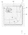
図2は基板Pを保持している基板ステージPST(Zチルトステージ52)を上方から見た平面図である。基板ステージPST(Zチルトステージ52)上において、基板Pの外側の所定位置には、上述したような空間像計測システム60のスリット部61を有するスリット板65が設けられている。
FIG. 2 is a plan view of the substrate stage PST (Z tilt stage 52) holding the substrate P as viewed from above. On the substrate stage PST (Z tilt stage 52), a
また、基板ステージPST上には、基板Pの外側の所定位置に基準部材300が配置されている。基準部材300には、基板アライメント系350により検出される基準マークPFMと、マスクアライメント系360により検出される基準マークMFMとが所定の位置関係で設けられている。基準部材300の上面300Aはほぼ平坦面となっており、基板ステージPSTに保持された基板P表面、及び基板ステージPST(Zチルトステージ52)の上面51とほぼ同じ高さ(面一)に設けられている。基準部材300の上面300Aは、フォーカス検出系30の基準面として使用することができる。
Further, a
また、基板ステージPST上には、基板Pの外側の所定位置に、例えば特開昭57−117238号公報に開示されているような照度ムラセンサ400の一部を構成する上板401が配置されている。上板401の上面401Aはほぼ平坦面となっており、基板ステージPSTに保持された基板Pの表面、及び基板ステージPSTの上面51とほぼ同じ高さ(面一)に設けられている。上板401の上面401Aには、光を通過可能なピンホール部470が設けられている。上面401Aのうち、ピンホール部470以外はクロムなどの遮光膜で覆われている。すなわち、ピンホール部470は遮光膜上に形成された凹部である。
On the substrate stage PST, an
また、基板ステージPST上には、基板Pの外側の所定位置に、例えば特開平11−16816号公報に開示されているような、照射量センサ(照度センサ)600の一部を構成する上板601が配置されている。上板601の上面601Aもほぼ平坦面となっており、基板ステージPSTに保持された基板Pの表面、及び基板ステージPSTの上面51とほぼ同じ高さ(面一)に設けられている。そして、この上板601の所定領域も光を受光(通過)可能に設けられている。
Further, on the substrate stage PST, an upper plate constituting a part of a dose sensor (illuminance sensor) 600 as disclosed in, for example, Japanese Patent Application Laid-Open No. 11-16816, at a predetermined position outside the substrate P. 601 is arranged. The
なお、特開昭62−183522号公報に開示されているような、投影光学系PLに入射する反射光量の計測に用いられる反射面を基板ステージPSTに配置してもよい。 Note that a reflection surface used for measuring the amount of reflected light incident on the projection optical system PL as disclosed in Japanese Patent Application Laid-Open No. 62-183522 may be disposed on the substrate stage PST.
次に、図3、図4、及び図5を参照しながら、空間像計測システム60のスリット板65の一例について説明する。図3はスリット板65近傍の拡大断面図、図4はスリット板65の平面図、図5は図4のA−A断面矢視図である。
Next, an example of the
図3、図4、及び図5において、スリット板65は、平面視長方形状のガラス板部材64の上面中央に設けられたクロム等からなる遮光膜62と、その遮光膜62の周囲、すなわちガラス板部材64の上面のうち遮光膜62以外の部分に設けられたアルミニウム等からなる反射膜63と、遮光膜62の一部に形成された開口パターンであるスリット部61とを備えている。スリット部61においては透明部材であるガラス板部材64が露出しており、光はスリット部61を透過可能である。また、スリット部61は、遮光膜62の一部に凹部を形成している。ガラス板部材64の形成材料としては、ArFエキシマレーザ光あるいはKrFエキシマレーザ光に対する透過性の良い合成石英あるいは螢石などが用いられる。スリット部61は、遮光膜62を例えばエッチング処理することで形成可能である。
3, 4, and 5, the
図3に示すように、Zチルトステージ52の上面51の一部には開口部51Kが形成されており、スリット板65は開口部51Kに嵌め込まれている。また、Zチルトステージ52の内部には、開口部51Kに接続する内部空間52Kが形成されており、空間像計測システム60の光学系74の一部は内部空間52Kに配置されている。光学系74の一部を構成する第1光学素子66は、Zチルトステージ52の内部空間52Kにおいてスリット部61の下方にガラス板部材64と一体的に配置されている。したがって、投影光学系PLの開口数NAが1以上の場合であっても、投影光学系PLからの光を、気体部分を通過することなしに、液体LQ、スリット部61、及びガラス板部材64を介して第1光学素子66に入射させることができる。
As shown in FIG. 3, an
図4に示すように、本実施形態において、遮光膜62の一部に形成されたスリット部61は、Y軸方向を長手方向とする矩形状(長方形状)のラインパターンであって、所定幅H1を有し、所定長さL1を有している。以下の説明においては、Y軸方向に延びるラインパターンを形成しているスリット部61を適宜、「第1パターン61」と称する。なお、第1パターンの数、形状、大きさなどは、本実施形態のようなラインパターンに限られず、空間像計測システム60による計測内容に応じて適宜変更することができる。
As shown in FIG. 4, in the present embodiment, the
ここで、本実施形態においては、スリット板65の上面65Aは、遮光膜62の上面及び反射膜63の上面を含むものとする。したがって、遮光膜62の上面と、反射膜63の上面と、基板ステージPSTの上面51とがほぼ面一となっており、空間像計測システム60を構成する第1パターン(スリット部)61は、基板ステージPSTの上面51及びスリット板65の上面65Aを含む所定面内に形成された構成となっている。
In this embodiment, the
スリット板65の上面65A上において、第1パターン61を含む第1領域S1の近傍に規定された第2領域S2には、X軸方向に延び、Y軸方向に並んで配置された複数のラインパターン81が形成されている。本実施形態においては、ラインパターン81は4つであるが、4つ以外の任意の複数であってもよい。
On the
図5に示すように、ラインパターン81は、第1パターン61同様、遮光膜62に形成された凹部である。ラインパターン81も、第1パターン61同様、遮光膜62を例えばエッチング処理することで形成可能である。本実施形態においては、第1パターン61の深さD1と、ラインパターン81の深さD2とはほぼ同じである。
As shown in FIG. 5, the
図4に示すように、ラインパターン81のそれぞれは、X軸方向を長手方向とする矩形状(長方形状)のラインパターンであって、所定幅H2を有し、所定長さL2を有している。以下の説明においては、Y軸方向に並んで配置された複数のラインパターン81を合わせて適宜、「第2パターン80」と称する。
As shown in FIG. 4, each of the
本実施形態において、複数のラインパターン81のそれぞれは同じ幅H2及び同じ長さL2を有している。また、ラインパターン81どうしのそれぞれの間隔もほぼ同じであり、本実施形態では、ラインパターン81どうしの間隔もH2となっている。また、ラインパターン81の幅H2と第1パターン61の幅H1ともほぼ同じとなっている(H1=H2)。一方、第2パターン80を構成するラインパターン81の長さL2は、第1パターン61の長さL1よりも長くなっている。
In the present embodiment, each of the plurality of
更には、第1パターン61の延長線と第2パターン80(ラインパターン81)とが交差する位置c1と、ラインパターン81の一端部c2との距離L2aは、第1パターン61の長さL1よりも長くなっている(L2a≧L1)。また、その位置c1とラインパターン81の他端部c3との距離L2bも、第1パターン61の長さL1よりも長くなっている(L2b≧L1)。なお、本実施形態では、第1パターン61の延長線とラインパターン81の中央とが交差するように設けられているため、距離L2aと距離L2bとはほぼ同じである。すなわち、本実施形態においては、L2a=L2b≧L1となっている。
Furthermore, the distance L2a between the position c1 where the extension line of the
本実施形態において、第1パターン61と第2パターン80とは所定距離だけ離れて設けられている。また、スリット板65の上面65A上において、第1パターン61と第2パターン80とで形成される図形の重心の位置(図4中、符号G参照)が、第1パターン61の外側に設けられるように、第1パターン61と第2パターン80とのそれぞれが所定の位置関係で形成されている。
In the present embodiment, the
次に、上述した構成を有する露光装置EXを用いて基板Pを露光する手順について図6のフローチャート図を参照しながら説明する。 Next, a procedure for exposing the substrate P using the exposure apparatus EX having the above-described configuration will be described with reference to the flowchart of FIG.
基板Pを露光する前に、まず、空間像計測システム60を使って投影光学系PLの結像特性を計測する処理が行われる。制御装置CONTは、空間像計測システム60を使った計測処理の開始を指令する(ステップSA1)。空間像計測システム60を使って計測処理を行うに際し、マスクステージMSTには、空間像計測用パターンが形成された計測用マスクが保持される。また、基板ステージPST(基板ホルダPH)上には、デバイスを形成するための基板Pが予め保持(ロード)されている。
Before the substrate P is exposed, first, a process for measuring the imaging characteristics of the projection optical system PL using the aerial
制御装置CONTは、液浸機構1を使って、投影光学系PLとスリット板65との間に液体LQの液浸領域AR2を形成する(ステップSA2)。液浸機構1は、第1パターン(スリット部)61が液体LQで覆われるようにスリット板65上に液浸領域AR2を形成する。
The control device CONT uses the
制御装置CONTは、照明光学系ILより露光光ELを射出する。露光光ELは、計測用マスク、投影光学系PL、及び液浸領域AR2の液体LQを通過した後、スリット板65に照射される(ステップSA3)。スリット板65の第1パターン61を通過した光は、光学系74のうち第1光学素子66に入射する。
The control device CONT emits exposure light EL from the illumination optical system IL. The exposure light EL passes through the measurement mask, the projection optical system PL, and the liquid LQ in the liquid immersion area AR2, and is then applied to the slit plate 65 (step SA3). The light that has passed through the
投影光学系PLとスリット板65との間の液浸領域AR2の液体LQによって投影光学系の開口数NAが向上するため、投影光学系PLの開口数NAに応じて、空間像計測システム60の第1光学素子66の開口数NAも向上させないと、第1光学素子66は、投影光学系PLを通過した光を良好に(全て)取り込むことができない可能性があり、光を良好に受光できなくなる。そこで、本実施形態においては、スリット板65の第1パターン61を通過した光が、気体空間を通過しないように第1光学素子66を配置しているので、第1光学素子66は投影光学系PLを介した光を良好に取り込むことができる。
Since the numerical aperture NA of the projection optical system is improved by the liquid LQ in the liquid immersion area AR2 between the projection optical system PL and the
第1光学素子66で集光された光は、この第1光学素子66を含む光学系74によって受光素子73に導かれる。このように、空間像計測システム60の受光素子73は、投影光学系PL、液浸領域AR2の液体LQ、及び第1パターン61を介して露光光ELを受光する。受光素子73は、受光量に応じた光電変換信号(光量信号)を信号処理装置を介して制御装置CONTに出力する。制御装置CONTは、受光素子73の受光結果に基づいて所定の演算処理を行い、投影光学系PL及び液体LQを介した結像特性を求める(ステップSA4)。
The light condensed by the first
第1パターン61を覆うようにスリット板65上に液浸領域AR2を形成した状態での空間像計測システム60による計測処理が完了した後、制御装置CONTは、基板ステージPSTをXY方向に移動し、投影光学系PLの像面側に形成されている液体LQの液浸領域AR2をスリット板65上より移動し、例えば照度ムラセンサ400の上板401上に移動する。そして、制御装置CONTは、投影光学系PL及び液浸領域AR2の液体LQを介して上板401に露光光ELを照射し、照度ムラセンサ400を使って投影領域AR1における露光光ELの照度ムラを求める。また、照度ムラセンサ400による計測処理が完了した後、制御装置CONTは、基板ステージPSTをXY方向に移動し、投影光学系PLの像面側に形成されている液体LQの液浸領域AR2を、例えば照射量センサ600の上板601上に移動する。そして、制御装置CONTは、投影光学系PL及び液浸領域AR2の液体LQを介して上板601に露光光ELを照射し、照射量センサ600を使って露光光ELの照度を求める。また、照射量センサ600による計測処理が完了した後、制御装置CONTは、基板ステージPSTをXY方向に移動し、投影光学系PLの像面側に形成されている液体LQの液浸領域AR2を、例えば基準部材300上に移動する。そして、制御装置CONTは、マスクアライメント系360を使って、投影光学系PL及び液浸領域AR2の液体LQを介して基準マークMFMを計測する。また、制御装置CONTは、基板アライメント系350を使って基準マークPFMを計測し、基板アライメント系350の検出基準位置とパターン像の投影位置との位置関係(ベースライン量)を、基板Pを露光する前に予め求めておく。
After the measurement processing by the aerial
なおここでは、空間像計測システム60のスリット板65上、照度ムラセンサ400の上板401上、照射量センサ600の上板601上、及び基準部材300上の順に液体LQの液浸領域AR2を移動して計測処理を順次行うように説明したが、計測する順序は上述の順序に限られず、任意に設定可能である。また、空間像計測システム60、照度ムラセンサ400、照射量センサ600、基準部材300の一部のみの計測動作を行うこともできるし、一部の計測動作を液体LQの液浸領域AR2を形成せずに実行してもよい。
Here, the liquid LQ immersion area AR2 is moved in order on the
そして、制御装置CONTは、空間像計測システム60を使った計測処理や、照度ムラセンサ400、照射量センサ600を使った計測処理に基づいて、投影光学系PLの結像特性の調整処理(キャリブレーション処理)などを行う(ステップSA5)。
Then, the control device CONT adjusts the imaging characteristics of the projection optical system PL (calibration) based on the measurement processing using the aerial
制御装置CONTは、基板Pの露光処理を行うために、基板ステージPSTをXY方向に移動し、投影光学系PLの像面側に形成されている液体LQの液浸領域AR2を基板P上に移動する。デバイス製造のために基板Pを露光するときには、当然のことながら、マスクステージMSTにはデバイスを形成するためのマスクMが保持される。そして、制御装置CONTは、照明光学系ILより露光光ELを射出し、マスクMを露光光ELで照明し、投影光学系PLと基板P上に形成された液浸領域AR2の液体LQとを介して基板P上にマスクMのパターン像を投影する(ステップSA6)。 The control device CONT moves the substrate stage PST in the XY directions in order to perform the exposure processing of the substrate P, and the liquid immersion area AR2 of the liquid LQ formed on the image plane side of the projection optical system PL on the substrate P. Moving. When exposing the substrate P for device manufacture, the mask M for forming a device is naturally held on the mask stage MST. Then, the control device CONT emits the exposure light EL from the illumination optical system IL, illuminates the mask M with the exposure light EL, and supplies the projection optical system PL and the liquid LQ in the liquid immersion area AR2 formed on the substrate P. Then, a pattern image of the mask M is projected onto the substrate P (step SA6).
なおここでは、投影光学系PLの像面側に液浸領域AR2を形成した状態で基板ステージPSTをXY方向に移動することで、スリット板65、上板401、601、基準部材300、及び基板Pのそれぞれを含む基板ステージPST上の任意の位置に液体LQの液浸領域AR2を移動しているが、基板ステージPST上において液浸領域AR2の位置を変えるときには、例えば第1の位置に形成されている液浸領域AR2の液体LQを液体回収機構20を使って回収した後、基板ステージPSTを移動し、第1の位置とは異なる第2の位置に液浸領域AR2を形成するために、液浸機構1による液体LQの供給及び回収動作を再開するようにしてもよい。具体的には、例えば液体LQを介した空間像計測システム60による計測処理が完了した後、制御装置CONTは、液浸機構1(液体回収機構20)を使ってスリット板65上の液体LQを回収する。そして、基板Pを液浸露光するときには、制御装置CONTは、基板ステージPSTをXY方向に移動して投影光学系PLと基板Pとを対向させ、その状態で液浸機構1による液体LQの供給及び回収動作を再開し、投影光学系PLと基板Pとの間に液体LQの液浸領域AR2を形成してから、基板Pを露光するようにしてもよい。
Here, by moving the substrate stage PST in the XY directions with the immersion area AR2 formed on the image plane side of the projection optical system PL, the
ところで、空間像計測システム60による計測処理が完了した後、液浸機構1(液体回収機構20)を使って第1パターン61(スリット板65)上の液体LQの回収動作を行ったにもかかわらず、あるいは基板ステージPSTをXY方向に移動してスリット板65上より液浸領域AR2の液体LQを他の位置に移動させたにもかかわらず、第1パターン61上に液体LQが残留する可能性がある。第1パターン61上に残留した液体LQを放置しておくと、その液体LQが気化して第1パターン61上にウォーターマークが形成され、次の計測処理のときに露光光ELは第1パターン61を良好に通過できず、計測精度の劣化を招くおそれがある。本実施形態においては、第1パターン61を含む第1領域S1の近傍に規定された第2領域S2には、残留した液体LQを第1領域S1より退かして第2領域S2に集めるように第2パターン80が形成されているので、第1領域S1の第1パターン61上から液体LQを退かすことができる。このことについて、図7A及び図7Bを参照しながら説明する。
Incidentally, after the measurement processing by the aerial
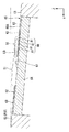
図7Aは、空間像計測システム60を使った計測処理が完了し、スリット板65上の液体LQの除去動作を行った後、そのスリット板65上に液体LQが残留している様子を模式的に示した断面図である。図7Aにおいて、液体LQは、第1パターン61を有する第1領域S1と、第2パターン80を有する第2領域S2とにまたがるようにして残留している。すなわち、この状態においては、液体LQは第1領域S1の第1パターン61上と、第2領域S2の第2パターン80上とに連続するように残留している。そして、時間経過に伴って液体LQが乾燥し、液体LQの体積が減少すると、スリット板65上の液体LQの稜線の+Y側の端部LG1、及び−Y側の端部LG2のそれぞれは、液体LQの中央側に向かって移動する(矢印y1、y2参照)。稜線の移動中においても、第1領域S1の表面の液体LQとの接触角θ1、及び第2領域S2の液体LQとの接触角θ2は維持される。図7Aにおいては、液体LQは第1領域S1において第1パターン61の底部(すなわちガラス板部材64)と接触しており、稜線の移動中において、ガラス板部材64の液体LQとの接触角θ1は維持される。同様に、液体LQは第2領域S2において遮光膜62と接触しており、稜線の移動中において、遮光膜62の液体LQとの接触角θ2は維持される。なお本実施形態においては、第1領域S1と液体LQとの親和性(すなわち接触角θ1)と、第2領域S2と液体LQとの親和性(すなわち接触角θ2)とはほぼ同じである。
FIG. 7A schematically illustrates a state in which the liquid LQ remains on the
図7Bは、図7Aに示す状態から所定時間経過後の液体LQの状態を模式的に示した断面図である。スリット板65上の液体LQの稜線の移動に伴って、やがて、図7Bに示すように、液体LQの端部LG2が第2パターン80のラインパターン81の内側に入り込む。ラインパターン81の内側に入り込んだ状態においても、ラインパターン81の内側面を形成する遮光膜62の液体LQとの接触角θ2が維持されようとするため、図7Bの符号Jで示すように、ラインパターン81の内側に入り込んだ液体LQの端部LG2の稜線が凹むように変形する。すると、液体LQには、ラインパターン81の内側面に接触したまま、液体LQの表面張力によって、凹んだ領域Jを元に戻そうとする力(膨らませようとする力)、すなわち液体LQの形状を維持しようとする力が発生する。この力により、第1パターン61に接触している液体LQの端部LG1がラインパターン81(第2パターン80)側に移動する現象が生じる(矢印y3参照)。このように、スリット板65の上面65Aに凹部からなる第2パターン80を設けておくことで、第2領域S2の液体LQは動きにくくなり、第2パターン80を有する第2領域S2は液体LQに対する親和性を向上されたように振る舞い、液体LQを保持する能力が増す。
FIG. 7B is a cross-sectional view schematically showing the state of the liquid LQ after a predetermined time has elapsed from the state shown in FIG. 7A. As the ridgeline of the liquid LQ on the
また、液体LQの端部LG2が、図7B中、例えば最も−Y側のラインパターン81Dから、その+Y側の隣のラインパターン81Cに移動した場合であっても、上述した現象が同様に生じる。したがって、液体LQのうち第2領域S2に配置されている端部LG2が液体LQの中央側(第1領域S1側)に向かって移動する速度は、液体LQのうち第1領域S1に配置されている端部LG1が液体LQの中央側(第2領域S2側)に向かって移動する速度よりも遅くなる。そして、本実施形態のように、Y軸方向を長手方向とするラインパターンからなる第1パターン61の近傍に、X軸方向を長手方向とするラインパターン81をY軸方向に関して並べて設け、上記現象を繰り返し生じさせることで、第1パターン61上に配置されている液体LQを、第1パターン61を含む第1領域S1より素早く退かし、第2領域S2に集めることができる。
In addition, even when the end portion LG2 of the liquid LQ moves from, for example, the
図8は、図7Bに示す状態から更に所定時間経過後の液体LQの状態を模式的に示した平面図である。上述したように、Y軸方向を長手方向とするラインパターンからなる第1パターン61の近傍に、X軸方向を長手方向とするラインパターン81をY軸方向に関して並べて設けたため、液体LQの第2領域S2に配置されている−Y側の端部LG2が液体LQの中央側(第1領域S1側)に向かって移動する速度v2は、液体LQの稜線のうち第1領域S1に配置されている+Y側の端部LG1が液体LQの中央側(第2領域S2側)に向かって移動する速度v1よりも十分に遅くなる。このように、第2領域S2に第2パターン80を形成したことにより、第1領域S1と第2領域S2とにまたがるようにして残留した液体LQは、第1パターン61を含む第1領域S1より退いて第2領域S2に集まる。
FIG. 8 is a plan view schematically showing the state of the liquid LQ after a predetermined time has elapsed from the state shown in FIG. 7B. As described above, since the
第2領域S2に集められた液体LQが気化することにより、第2領域S2にウォーターマークが形成される可能性があるが、第2領域S2は、空間像計測システム60の計測に使用されないため、第2領域S2にウォーターマークが形成されても問題にならない。もちろん、第2領域S2に集めた(凝集させた)液体LQを、そのまま放置せずに、液体回収機構20を使って回収してもよい。
The liquid LQ collected in the second region S2 may be vaporized to form a watermark in the second region S2. However, the second region S2 is not used for measurement by the aerial
以上説明したように、空間像計測システム60を構成する第1パターン61を含む第1領域S1とその近傍に規定された第2領域S2とにまたがるようにして液体LQが残留した場合において、第2領域S2に形成されている第2パターン80によって、液体LQは第1領域S1より退いて第2領域S2に集まる。したがって、第1パターン61を含む第1領域S1上に液体LQが残留することを防止できる。したがって、空間像計測システム60の第1パターン61上にウォーターマークが形成されることを防止でき、残留した液体LQやウォーターマークに起因する空間像計測システム60の計測精度の劣化を防止できる。
As described above, when the liquid LQ remains so as to extend over the first region S1 including the
第1領域S1での液体LQの残留を防止するために、第1領域S1を例えばフッ素系樹脂等の撥液性材料を使って表面処理(撥液化処理)することもできる。ところが、そのような撥液性材料においては、紫外光である露光光ELの照射によりその撥液性が経時的に劣化する可能性が高い。すなわち、第1領域S1又は第2領域S2を表面処理することによって、第1領域S1に残留した液体LQをその第1領域S1より退かそうとする構成では、液体LQを退かす能力が経時的に劣化する。本実施形態においては、凹部からなる第2パターン80によって、すなわち、第2領域S2に形成した物理的な形状を使って液体LQを第1領域S1より退かす構成であるため、液体LQを退かす能力は経時的に劣化せず、第1パターン61を含む第1領域S1から液体LQを円滑に退かすことができる。
In order to prevent the liquid LQ from remaining in the first region S1, the first region S1 can be subjected to a surface treatment (liquid repellency treatment) using a liquid repellent material such as a fluorine-based resin. However, in such a liquid repellent material, there is a high possibility that the liquid repellency deteriorates with time due to irradiation of exposure light EL which is ultraviolet light. That is, in the configuration in which the liquid LQ remaining in the first region S1 is retreated from the first region S1 by surface-treating the first region S1 or the second region S2, the ability to retreat the liquid LQ is time-dependent. Deteriorates. In the present embodiment, since the liquid LQ is retreated from the first region S1 by the
また、図4を参照して説明したように、スリット板65の上面65A上において、第1パターン61と第2パターン80とで形成される図形の重心の位置Gは、第1パターン61よりも外側にあるので、第2パターン80は、第1領域S1と第2領域S2とにまたがるようにして残留した液体LQを第1パターン61より退かして第1パターン61の外側により確実に集めることができる。
As described with reference to FIG. 4, the position G of the center of gravity of the figure formed by the
また、第2パターン80を形成するラインパターン81の長さL2は、第1パターン61の長さL1よりも長く、第1パターン61の延長線とラインパターン81との位置c1とラインパターン81の両端部c2、c3のそれぞれとの距離L2a、L2bも第1パターン61の長さL1よりも長いため、第1パターン61上に残留した液体LQをより確実に第2領域S2に引き込むことができる。すなわち、図8に示すように、液体LQの稜線が第2領域S2の位置Gに向かって移動するときの移動成分としては、第1パターン61に沿ってほぼX軸方向に移動する成分y4と、第2パターン80(ラインパターン81)に沿ってほぼY軸方向に移動する成分y5、y6とがある。仮に、第2パターン80を形成するラインパターン81の長さL2a、L2bが、第1パターン61の長さL1よりも短いと、第1パターン61に沿ってY軸方向に移動する液体LQの稜線の+Y側の端部LG1が第1パターン61より外側に出て第2領域S2に配置される前に、第2パターン80(ラインパターン81)に沿ってX軸方向に移動する液体LQの稜線の+X側の端部LG3及び−X側の端部LG4の移動が止まる現象が生じやすくなる。すると、端部LG3、LG4の移動の停止に伴って、端部LG1の移動も停止する可能性が高くなるため、第1パターン61上から液体LQを完全に退かすことができなくなるおそれがある。本実施形態においては、第1パターン61の延長線とラインパターン81との位置c1とラインパターン81の両端部c2、c3のそれぞれとの距離L2a、L2bを第1パターン61の長さL1よりも長くしたので、液体LQが第1パターン61上から退くまで、端部LG1、LG3、LG4の移動を持続することができ、第1パターン61上に残留した液体LQをより確実に第2領域S2に引き込むことができる。
The length L2 of the
<第2の実施形態>
次に、第2の実施形態について図9を参照しながら説明する。以下の説明において、上述した実施形態と同一又は同等の構成部分については同一の符号を付し、その説明を簡略もしくは省略する。<Second Embodiment>
Next, a second embodiment will be described with reference to FIG. In the following description, the same or equivalent components as those in the above-described embodiment are denoted by the same reference numerals, and the description thereof is simplified or omitted.
図9において、第1パターン61の延長線と第2パターン80(ラインパターン81)とが交差する位置c1と、ラインパターン81の一端部c2との距離L2aは、第1パターン61の長さL1よりも長くなっている。また、その位置c1とラインパターン81の他端部c3との距離L2bも、第1パターン61の長さL1よりも長くなっている。そして、位置c1とラインパターン81の一端部c2との距離L2aは、位置c1とラインパターン81の他端部c3との距離L2bよりも長くなっている。すなわち、本実施形態においては、L2a>L2b≧L1となっている。これにより、第1パターン61と第2パターン80とで形成される図形の重心の位置G'は、第1パターン61よりも外側であって、且つ第1パターン61の延長線とは離れた位置に設けられる。このような構成とすることで、第2パターン80は、第1領域S1と第2領域S2とにまたがるようにして残留した液体LQを第1パターン61より退かして、第1パターン61の外側であって、且つ第1パターン61の延長線とは離れた位置に集めることができる。したがって、第2領域S2に集められた後の液体LQが、仮に拡散する状況が生じた場合でも、その拡散した液体LQが第1パターン61上に再び配置される可能性を低減することができる。
In FIG. 9, the distance L2a between the position c1 where the extension line of the
<第3の実施形態>
次に、第3の実施形態について図10を参照しながら説明する。図10において、第1パターン61の−Y側の一端部と、第2パターン80のうち最も+Y側に配置されたラインパターン81の中央部とが接続している。そして、第1パターン61の端部と第2パターン80とが接続する接続位置と、第2パターン80の端部との距離は、第1パターン61よりも長くなっている。このような構成とすることによっても、第2パターン80によって、第1領域S1と第2領域S2とにまたがるようにして残留した液体LQを、第1領域S1より退けて第2領域S2に集めることができる。<Third Embodiment>
Next, a third embodiment will be described with reference to FIG. In FIG. 10, one end portion on the −Y side of the
<第4の実施形態>
次に、第4の実施形態について図11を参照しながら説明する。図11において、第2パターン80を構成する複数のラインパターン81A〜81Dのそれぞれの幅は互いに異なっている。具体的には、Y軸方向に並んだ複数のラインパターン81A〜81Dのうち、第1パターン61に最も近くに形成されている(最も+Y側に形成されている)ラインパターン81Aの幅が最も狭く、−Y側に向かうにつれて漸次太くなっている。そして、本実施形態においては、第1パターン61の幅とラインパターン81Bの幅とが同じになっている。このように、第2パターン80を構成するラインパターン81の幅が、第1パターン61の幅と異なっていたり、複数のラインパターン81のそれぞれの幅が互いに異なっている構成であっても、第2パターン80によって、第1領域S1と第2領域S2とにまたがるようにして残留した液体LQを、第1領域S1より退けて第2領域S2に集めることができる。<Fourth Embodiment>
Next, a fourth embodiment will be described with reference to FIG. In FIG. 11, the widths of the plurality of
<第5の実施形態>
次に、第5の実施形態について図12を参照しながら説明する。図12において、第2パターン80を構成する複数のラインパターン81A〜81Dのそれぞれは、Y軸に関して互いに異なる角度で形成されている。具体的には、Y軸方向に並んだ複数のラインパターン81A〜81Dのうち、第1パターン61に最も近くに形成されている(最も+Y側に形成されている)ラインパターン81AがY軸方向とほぼ平行に形成されており、−Y側に向かうにつれてY軸方向との角度が漸次大きくなっている。このような構成とすることによっても、第2パターン80によって、第1領域S1と第2領域S2とにまたがるようにして残留した液体LQを、第1領域S1より退けて第2領域S2に集めることができる。<Fifth Embodiment>
Next, a fifth embodiment will be described with reference to FIG. In FIG. 12, each of the plurality of
<第6の実施形態>
次に、第6の実施形態について図13を参照しながら説明する。図13において、第1パターン61の深さD1と、第2パターン80を構成するラインパターン81の深さD2とは互いに異なっている。具体的には、第1パターン61は第2パターン80のラインパターン81よりも深く形成されている(D1>D2)。第1パターン61は遮光膜62をエッチング処理して完全に除去することで形成され、その第1パターン61においてはガラス板部材64が露出しているが、第2パターン80(ラインパターン81)は、ソフトエッチングにより遮光膜62を完全に除去せずに一部残すことで、第1パターン61の深さD1よりも浅く形成されている。そして、第2パターン80(ラインパターン81)においては、ガラス板部材64は露出しておらず、クロムからなる遮光膜62で被覆されている。このような構成とすることにより、スリット板65に露光光ELが照射されたとき、露光光ELは第1パターン61を通過するが、第2パターン80(ラインパターン81)を通過しない。したがって、第2パターン80を通過した露光光ELが第1光学素子66に入射して、空間像計測システム60の計測精度が劣化するといった不都合を防止することができる。<Sixth Embodiment>
Next, a sixth embodiment will be described with reference to FIG. In FIG. 13, the depth D1 of the
一方、上述した第1〜第5の実施形態などでは、第2パターン80(ラインパターン81)においてもガラス板部材64が露出している。そのため、スリット板65に露光光ELが照射されたとき、露光光ELは第1パターン61に加えて、第2パターン80(ラインパターン81)も通過するおそれがあるが、第1パターン61に露光光ELを照射したとき、露光光ELが第2パターン80を通過しないように、且つ第2パターン80が第1領域S1と第2領域S2とにまたがるようにして残留した液体LQを、第1領域S1より退けて第2領域S2に集めることができるように、第1パターン61と第2パターン80とを所定の位置関係で形成することで、上記不都合を防止できる。
On the other hand, in the first to fifth embodiments described above, the
<第7の実施形態>
次に、第7の実施形態について図14を参照しながら説明する。図14において、第1パターン61の深さD1と、第2パターン80を構成するラインパターン81の深さD2とは互いに異なっており、第2パターン80のラインパターン81は第1パターン61よりも深く形成されている(D2>D1)。本実施形態においては、第2パターン80(ラインパターン81)に対応するガラス板部材64の一部がエッチングされている。このように、第1領域S1の表面に形成された凹部からなる第1パターン61に対して、第2領域S2の表面に第1パターン61よりも深い凹部からなる第2パターン80(ラインパターン81)を設けることで、第2領域S2においては液体LQを保持する能力が更に増すため、第1領域S1と第2領域S2とにまたがるようにして残留した液体LQを、より円滑に第1領域S1より退かして第2領域S2に集めることができる。<Seventh Embodiment>
Next, a seventh embodiment will be described with reference to FIG. In FIG. 14, the depth D1 of the
<第8の実施形態>
次に、第8の実施形態について図15を参照しながら説明する。図15において、第1パターン61を構成する凹部には、例えばSiO2等の所定材料61'が配置されている。そして、凹部61に配置された所定材料61'の上面と、遮光膜62の上面とはほぼ面一となっている。すなわち、露光光ELが通過する第1パターン61を含む第1領域S1には段差(凹部)が形成されていない。こうすることにより、第1領域S1に液体LQが残留する不都合をより確実に防止することができる。<Eighth Embodiment>
Next, an eighth embodiment will be described with reference to FIG. In FIG. 15, a
<第9の実施形態>
次に、第9の実施形態について図16を参照しながら説明する。図16において、ラインパターン81の断面形状は、上側(遮光膜62の上面側)から下側(ガラス板部材64側)に向かって漸次拡がるようにテーパ形状に形成されている。こうすることにより、ラインパターン81を有する第2領域S2においては液体LQを保持する能力が更に増すため、第1領域S1と第2領域S2とにまたがるようにして残留した液体LQを、より円滑に第1領域S1より退かして第2領域S2に集めることができる。<Ninth Embodiment>
Next, a ninth embodiment will be described with reference to FIG. In FIG. 16, the cross-sectional shape of the
<第10の実施形態>
次に、第10の実施形態について図17を参照しながら説明する。図17において、凹部からなるラインパターン81を含む第2領域S2の表面が、第1領域S1の表面よりも粗くなっている。第2領域S2の表面を粗くするために、本実施形態においては、第2領域S2に対してサンドブラスト加工が施されている。こうすることによっても、第2領域S2においては液体LQを保持する能力が更に増すため、第1領域S1と第2領域S2とにまたがるようにして残留した液体LQを、より円滑に第1領域S1より退かして第2領域S2に集めることができる。<Tenth Embodiment>
Next, a tenth embodiment will be described with reference to FIG. In FIG. 17, the surface of the second region S <b> 2 including the
<第11の実施形態>
次に、第11の実施形態について図18を参照しながら説明する。図18において、第1パターン61を含む第1領域S1を形成する遮光膜62と、第2パターン80を含む第2領域S2を形成する遮光膜62'とは、互いに異なる材料によって形成されている。そして、遮光膜62'を形成する材料は、遮光膜62を形成する材料よりも液体LQに対して親液性を有している。これにより、凹部であるラインパターン81の内壁面を含む第2領域S2の表面は、凹部である第1パターン61の内壁面を含む第1領域S2の表面よりも液体LQに対して親液性となっている。こうすることにより、第2領域S2においては液体LQを保持する能力が更に増すため、第1領域S1と第2領域S2とにまたがるようにして残留した液体LQを、より円滑に第1領域S1より退かして第2領域S2に集めることができる。なお、第1〜第10の実施形態のように、第1領域S1及び第2領域S2のそれぞれに遮光膜62を設け、その遮光膜62のうち第2領域S2に対応する領域の表面に、遮光膜62よりも親液性を有する親液性材料をコーティングすることで、第2領域S2の表面を第1領域の表面よりも液体LQに対して親液性にすることもできる。逆に、遮光膜62のうち第1領域S1に対応する領域の表面に、遮光膜62よりも撥液性を有する撥液性材料をコーティングするようにしてもよい。<Eleventh embodiment>
Next, an eleventh embodiment will be described with reference to FIG. In FIG. 18, the
<第12の実施形態>
次に、第12の実施形態について図19を参照しながら説明する。図19において、第2パターン80Eを構成するラインパターン81Eは、スリット板65の上面65Aよりも上方に突出した凸部により構成されている。本実施形態においては、スリット板65の上面65A(遮光膜62の上面)上にSiO2からなる凸部が設けられている。このような構成とすることによっても、第1領域S1と第2領域S2とにまたがるようにして残留した液体LQを、第1領域S1より退かして第2領域S2に集めることができる。もちろん、第2パターン80としては、凸部と凹部とのそれぞれを含む構成であってもよい。<Twelfth Embodiment>
Next, a twelfth embodiment will be described with reference to FIG. In FIG. 19, the
<第13の実施形態>
次に、第13の実施形態について図20を参照しながら説明する。図20において、第2パターン80Fは、平面視略円形状の小さい凸部81Fを複数並べたドット状パターンによって構成されている。このような構成とすることによっても、第1領域S1と第2領域S2とにまたがるようにして残留した液体LQを、第1領域S1より退かして第2領域S2に集めることができる。もちろん、ドット状パターンとしては、平面視略円形状の小さい凹部を複数並べた構成であってもよいし、凸部と凹部とのそれぞれを含む構成であってもよい。<13th Embodiment>
Next, a thirteenth embodiment will be described with reference to FIG. In FIG. 20, the
<第14の実施形態>
次に、第14の実施形態について図21を参照しながら説明する。図21において、第2パターン80Gは、X軸方向に延びる短い溝部81Gと、Y軸方向に延びる短い溝部81Hとを、XY方向に関して規則的に並べて形成し、これら溝部81G、81Hを互いに接続して略格子状とした格子状パターンによって構成されている。これら溝部81G、81Hは、遮光膜62をエッチングすることで形成可能である。このような構成とすることによっても、第1領域S1と第2領域S2とにまたがるようにして残留した液体LQを、第1領域S1より退かして第2領域S2に集めることができる。なお、例えば遮光膜62の上にSiO2等からなるタイル状の複数の凸部を並べることによって、図21に示すような格子状パターンを形成してもよい。<Fourteenth embodiment>
Next, a fourteenth embodiment will be described with reference to FIG. In FIG. 21, the
なお、上述の第1〜第14の実施形態においては、第2領域S2に第2パターンを設けているが、第2パターンを設けずに、第2領域S2表面の液体LQとの親和性を、第1領域S1表面の液体LQとの親和性よりも高くするだけでもよい。すなわち、第2領域S2表面での液体LQの接触角が、第1領域S1表面での液体LQの接触角よりも小さくなるように、第1領域S1と第2領域S2との少なくとも一方の表面処理を行ってもよい。 In the first to fourteenth embodiments described above, the second pattern is provided in the second region S2, but the affinity with the liquid LQ on the surface of the second region S2 is provided without providing the second pattern. The affinity with the liquid LQ on the surface of the first region S1 may only be increased. That is, at least one surface of the first region S1 and the second region S2 such that the contact angle of the liquid LQ on the surface of the second region S2 is smaller than the contact angle of the liquid LQ on the surface of the first region S1. Processing may be performed.
<第15の実施形態>
次に、第15の実施形態について図22を参照しながら説明する。図22は、スリット板65が配置された基板ステージPST(Zチルトステージ52)の上面51の一部を示す平面図である。上述したように、基板ステージPSTの上面51は撥液性を有しているが、本実施形態においては、撥液性を有する基板ステージPSTの上面51の一部に親液性領域W1が設けられ、その親液性領域W1の内側にスリット板65が配置されている。すなわち、図22において、基板ステージPSTの上面51上には、親液性領域W1と、その親液性領域W1の外側に配置された撥液性領域W2とが設けられている。このような親液性領域W1と撥液性領域W2とは、例えば基板ステージPSTの上面51に施された撥液性の被膜を、一部の領域(親液性領域W1に対応する領域)だけ除去することによって形成することができる。<Fifteenth embodiment>
Next, a fifteenth embodiment will be described with reference to FIG. FIG. 22 is a plan view showing a part of the
そして、スリット板65の第1パターン61を含む第1領域S1は、親液性領域W1内において、親液性領域W1の中心(重心、図心)からはずれた位置に配置されている。例えば、親液性領域W1のほぼ全面を覆うように液体LQが残留した場合、液体LQは親液性領域W1の中心(中央部)G''に集まろうとする。すなわち、図22の実施形態においては、スリット板65(第1領域S1)の周りの親液性領域W1も、第1パターン61を含む第1領域S1から残留した液体LQを退かす第2領域S2として機能する。したがって、図22の実施形態においても、第1パターン61を含む第1領域S1に液体LQが残留することを防止することができる。
The first region S1 including the
なお、第15の実施形態においては、スリット板65上には第2パターン80を含む第2領域S2が形成されているが、スリット板65上の第2領域S2(第2パターン80)は省略することができる。また、第15の実施形態においては、第1領域S1の表面よりも親液性領域W1表面の液体LQに対する親和性を高くしておくことによって、より確実に残留した液体LQを第1パターン61を含む第1領域S1から退かすことができる。また、撥液性の膜は、紫外域の光(露光光EL)の照射によって劣化するため、計測に用いられる第1パターン61が撥液性の膜で覆われていると、露光光ELの照射により撥液性の膜が劣化して、第1パターン61を用いる計測精度を劣化させる可能性があるが、本実施形態においては、基板ステージPSTの上面51のうち第1パターン61を含む所定領域の撥液性の膜が部分的に除去されているため、撥液性の膜の劣化に起因する計測精度の悪化を防止することもできる。
In the fifteenth embodiment, the second region S2 including the
<第16の実施形態>
次に、第16の実施形態について図23を参照しながら説明する。図23において、基板ステージPSTの上面51上には、上述した第15の実施形態同様、親液性領域W1と、その親液性領域W1の外側に配置された撥液性領域W2とが設けられている。スリット板65は親液性領域W1の内側に配置されており、スリット板65の第1パターン61を含む第1領域S1は、親液性領域W1内において、親液性領域W1の中心(重心、図心)からはずれた位置に配置されている。そして、親液性領域W1と撥液性領域W2との境界エッジ部EGのうち、スリット板65(第1パターン61)から離れた境界エッジ部EGのエッジ形状は、平面視において鋸歯状に形成されている。本実施形態においては、親液性領域W1はほぼ矩形状(四角形状)であって境界エッジ部EGは4つの辺を有しており、その辺に対応する境界エッジ部EG1〜EG4のうちスリット板65から離れた境界エッジ部EG1、EG2が鋸歯状に形成されている。所定方向に関して占める領域の大きさがほぼ同じ場合においては、鋸歯状に形成された境界エッジ部のエッジ長さは、鋸歯状に形成されていない境界エッジ部のエッジ長さよりも長くなる。すなわち、Y軸方向に関して占める領域の大きさがほぼ同じであって互いに対向する境界エッジ部EG1、EG3のうち、鋸歯状に形成された境界エッジ部EG1のエッジ長さは、対向する境界エッジ部EG3のエッジ長さよりも長い。同様に、X軸方向に関して占める領域の大きさがほぼ同じであって互いに対向する境界エッジ部EG2、EG4のうち、鋸歯状に形成された境界エッジ部EG2のエッジ長さは、対向する境界エッジ部EG4のエッジ長さよりも長い。<Sixteenth Embodiment>
Next, a sixteenth embodiment will be described with reference to FIG. In FIG. 23, the lyophilic region W1 and the lyophobic region W2 disposed outside the lyophilic region W1 are provided on the
このように、境界エッジ部EG(EG1〜EG4)のうち、スリット板65から離れた一部の境界エッジ部EG(EG1、EG2)を鋸歯状にして、その境界エッジ部EG1、EG2のエッジ長さを長くすることで、その境界エッジ部EG1、EG2における親液性領域W1のエッジの長さを実質的に長くすることができる。したがって、親液性領域W1のほぼ全面を覆うように、親液性領域W1と撥液性領域W2とにまたがるようにして残留した液体LQは、境界エッジ部E1、E2において動きにくくなり、境界エッジ部EG1、EG2に集まろうとする。したがって、その境界エッジ部EG1、EG2に対して離れた位置にある第1パターン61を含むスリット板65(第1領域S1)上に液体LQが残留しても、その液体LQを退かすことができる。
Thus, of the boundary edge portions EG (EG1 to EG4), a part of the boundary edge portions EG (EG1, EG2) apart from the
なお、本実施形態においては、境界エッジ部EG1、EG2は鋸歯状に形成されているが、鋸歯状でなくてもよい。すなわち、所定方向に関して占める領域の大きさがほぼ同じ境界エッジ部が複数形成された場合、スリット板65と離れた位置に設けられた境界エッジ部EG1、EG2のエッジ長さが、スリット板65に近い位置に設けられた境界エッジ部EG3、EG4のエッジ長さよりも長くなるように形成されていればよい。また、本実施形態においては、四角形状に形成された境界エッジ部EGのうち、スリット板65から離れた2つの辺の境界エッジ部EG1、EG2を鋸歯状に形成しているが、1つの境界エッジ部だけが鋸歯状であってもよい。また、境界エッジ部EG(親液性領域W1)は四角形状でなくてもよく、任意の形状(円形状、楕円形状、四角形以外の多角形状)であってもよい。
なお、本実施形態においても、基板ステージPSTの上面51のうち第1パターン61を含む所定領域の撥液性の膜が部分的に除去されているため、撥液性の膜の劣化に起因する計測精度の悪化を防止することもできる。In the present embodiment, the boundary edge portions EG1 and EG2 are formed in a sawtooth shape, but may not be in a sawtooth shape. That is, when a plurality of boundary edge portions having substantially the same area size in the predetermined direction are formed, the edge lengths of the boundary edge portions EG1 and EG2 provided at positions separated from the
In this embodiment as well, the liquid repellent film in a predetermined region including the
<第17の実施形態>
次に、第17の実施形態について図24を参照しながら説明する。図24において、基板ステージPSTの上面51上には、上述した第15、第16の実施形態同様、親液性領域W1と、その親液性領域W1の外側に配置された撥液性領域W2とが設けられている。
スリット板65は親液性領域W1の内側に配置されており、スリット板65の第1パターン61を含む第1領域S1は、親液性領域W1内において、親液性領域W1の中心(重心、図心)からはずれた位置に配置されている。そして、親液性領域W1と撥液性領域W2との境界エッジ部EG(EG1〜EG4)のうち、スリット板65(第1パターン61)から離れた境界エッジ部EG(EG1、EG2)近傍の親液性領域W1に、微小撥液性領域W2'が複数設けられている。本実施形態においては、微小撥液性領域W2'は平面視矩形状に形成されており、親液性領域W1の内側において、境界エッジ部EG1、EG2に沿って複数設けられている。なお、微小撥液性領域W2'の形状は矩形状に限らず、円形状など任意の形状でよい。<Seventeenth embodiment>
Next, a seventeenth embodiment will be described with reference to FIG. In FIG. 24, on the
The
こうすることによっても、その境界エッジ部EG1、EG2における親液性領域W1のエッジの長さが実質的に長くなる。したがって、残留した液体LQは、境界エッジ部E1、E2近傍において動きにくくなり、境界エッジ部EG1、EG2近傍に集まろうとする。したがって、その境界エッジ部EG1、EG2に対して離れた位置にある第1パターン61を含むスリット板65(第1領域S1)上に液体LQが残留しても、その液体LQを退かすことができる。
なお、本実施形態においても、基板ステージPSTの上面51のうち第1パターン61を含む所定領域の撥液性の膜が部分的に除去されているため、撥液性の膜の劣化に起因する計測精度の悪化を防止することもできる。This also substantially increases the edge length of the lyophilic region W1 at the boundary edge portions EG1, EG2. Accordingly, the remaining liquid LQ becomes difficult to move in the vicinity of the boundary edge portions E1 and E2, and tends to gather in the vicinity of the boundary edge portions EG1 and EG2. Therefore, even if the liquid LQ remains on the slit plate 65 (first region S1) including the
In this embodiment as well, the liquid repellent film in a predetermined region including the
<第18の実施形態>
次に、第18の実施形態について図25を参照しながら説明する。図25において、基板ステージPSTの上面51上には、上述した第15〜第17の実施形態同様、親液性領域W1と、その親液性領域W1の外側に配置された撥液性領域W2とが設けられている。
スリット板65は親液性領域W1の内側に配置されており、スリット板65の第1パターン61を含む第1領域S1は、親液性領域W1内において、親液性領域W1の中心(重心、図心)からはずれた位置に配置されている。そして、親液性領域W1と撥液性領域W2との境界エッジ部EG(EG1〜EG4)のうち、スリット板65(第1パターン61)から離れた境界エッジ部EG(EG1、EG2)近傍の親液性領域W1に、図20を参照して説明した第13の実施形態のような、平面視略円形状の小さい凸部81Fが複数設けられている。凸部81Fは、親液性領域W1の内側において、境界エッジ部EG1、EG2に沿って複数設けられており、ドット状パターンを形成している。<Eighteenth embodiment>
Next, an eighteenth embodiment will be described with reference to FIG. In FIG. 25, on the
The
こうすることにより、第13の実施形態同様、残留した液体LQを凸部81Fからなるドット状パターンに集めることができる。なお、ドット状パターンとしては、第13の実施形態同様、平面視略円形状の小さい凹部を複数並べた構成であってもよいし、凸部と凹部とのそれぞれを含む構成であってもよい。また、凸部又は凹部は、平面視略円形状に限られず、液体LQを集めることができる程度の適当な形状を有し、適当な密集性で配置されていればよい。なお、凸部又は凹部は、メタル(金属)で形成されていてもよい。メタルで凸部又は凹部を形成した場合には、メタルの親液性と相まって、より一層、液体LQが動きにくくなり、残留した液体LQを集めやすくなる。
なお本実施形態においても、基板ステージPSTの上面51のうち第1パターン61を含む所定領域の撥液性の膜が部分的に除去されているため、撥液性の膜の劣化に起因する計測精度の悪化を防止することもできる。By so doing, the remaining liquid LQ can be collected in a dot-like pattern composed of the
Also in this embodiment, since the liquid repellent film in a predetermined region including the
なお、上述の第1〜第18の実施形態において、詳細な説明は省略したが、照度ムラセンサ400及び照射量センサ600についても、光透過部を通過した光が気体空間を通過することなしに、第1光学素子66のような集光光学部材に入射する構成となっている。
In the first to eighteenth embodiments described above, the detailed description is omitted, but the
また、上述の第1〜第18の実施形態において、空間像計測システム60、照度ムラセンサ400、照射量センサ600の光透過部を通過した光を、第1光学素子66のような集光光学部材を使わずに、受光素子に直接入射させるようにしてもよいし、第1光学素子66のような集光光学部材や受光素子と光透過部との間を屈折率が1よりも大きい液体(例えば純水)で満たすこともできる。
Further, in the first to eighteenth embodiments described above, the light that has passed through the light transmission portions of the aerial
<第19の実施形態>
次に、第19の実施形態について図26を参照しながら説明する。図26は、マスクアライメント系360で計測される基準マークMFMを示す図である。基準マークMFMは、マスクアライメント系360によって計測される第1パターン61Kと、第1パターン61Kに接続する第2パターン80Kとを有している。第1パターン61Kは、4つのラインアンドスペースパターン61Lを組み合わせて矩形状に配置したものであって、マスクアライメント系360の計測領域に応じた基準部材300上の第1領域S1に設けられている。第2パターン80Kも、第1パターン61Kの4つのラインアンドスペースパターン61Lのそれぞれに接続するラインアンドスペースパターン81Lによって構成されている。第2パターン80Kは、第1領域S1の外側の第2領域S2に設けられており、第1領域S1に対して離れる方向に延びるように形成されている。このような構成とすることによっても、第2パターン80Kは、第1領域S1と第2領域S2とにまたがるようにして残留した液体LQを、第1領域S1より退かして第2領域S2に集めることができる。また、図27に示すように、第2パターン80Kを構成するラインアンドスペースパターン81Lを途中で曲げるように形成してもよい。
なお、基板アライメント系350で計測される基準マークPFM上に液体LQが残留する可能性がある場合には、基準マークMFMと同様にして、基準マークPFMを含む第1領域S1から残留した液体LQを退かして、第2領域S2に集めることができる。<Nineteenth embodiment>
Next, a nineteenth embodiment will be described with reference to FIG. FIG. 26 is a diagram showing the reference mark MFM measured by the
If there is a possibility that the liquid LQ may remain on the reference mark PFM measured by the
なお、上述した第1〜第18の実施形態においては、空間像計測システム60のスリット板65上に残留した液体LQを第1領域S1から退ける場合を例にして説明したが、基板ステージPST上には、図2を参照して説明したように、例えば照度ムラセンサ400の一部を構成するピンホール部(ホールパターン)470を有する上板401が配置されており、第1〜第18の実施形態と同様にして、ピンホール部470を含む第1領域と第2領域とにまたがるようにして残留した液体LQを第1領域より退かして第2領域に集めることができる。また、照射量センサ600の上板601についても、上述の第1〜第18の実施形態と同様にして、光透過部を含む第1領域から残留した液体LQを退かして第2領域に集めることができる。
In the first to eighteenth embodiments described above, the case where the liquid LQ remaining on the
更に、上述したように基板ステージPST上に反射光量を計測するための反射面が配置されている場合にも、上述の第1〜第18の実施形態と同様にして、その反射面の少なくとも一部を含む第1領域から残留した液体LQを退かしてその近傍の第2領域に集めることができる。
また、基板ステージPST上の基準マークMFM及び/又はPFM上に液体LQが残留する可能性がある場合には、上述の第15〜第18の実施形態と同様にして、基準マークMFM及び/又はPFMを含む第1領域S1から残留した液体LQを退かして、その近傍の第2領域S2に集めることができる。Further, even when the reflection surface for measuring the amount of reflected light is arranged on the substrate stage PST as described above, at least one of the reflection surfaces is the same as in the first to eighteenth embodiments. The liquid LQ remaining from the first region including the portion can be withdrawn and collected in the second region in the vicinity thereof.
When there is a possibility that the liquid LQ may remain on the reference mark MFM and / or PFM on the substrate stage PST, the reference mark MFM and / or the same as in the fifteenth to eighteenth embodiments described above. The liquid LQ remaining from the first region S1 containing PFM can be withdrawn and collected in the second region S2 in the vicinity thereof.
また更に、基板ステージPSTに搭載する計測器として、国際公開第99/60361号パンフレットや、US特許第6650399号などに開示されている波面収差の計測器を採用することもでき、この場合も上述の第1〜第18の実施形態と同様にして、光透過部を含む第1領域から残留した液体を退かして第2領域に集めることができる。 Furthermore, as a measuring instrument mounted on the substrate stage PST, a wavefront aberration measuring instrument disclosed in International Publication No. 99/60361 pamphlet, US Pat. No. 6,650,399, or the like can be adopted. In the same manner as in the first to eighteenth embodiments, the liquid remaining from the first region including the light transmission part can be retracted and collected in the second region.
なお、上述した第1〜第19の実施形態においては、第1パターンは凹部によって構成されているが、凸部であってもよいし、凹部と凸部とのそれぞれを含むものであってもよい。 In the first to nineteenth embodiments described above, the first pattern is constituted by a concave portion, but may be a convex portion or may include a concave portion and a convex portion. Good.
<第20の実施形態>
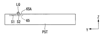
上述した各実施形態においては、第2領域S2に設けられた第2パターン80は凹部及び凸部のうち少なくともいずれか一方によって構成されているが、例えば第2領域S2に第2パターン80を設けなくても、第1領域S1の表面と第2領域S2の表面との少なくとも一方に所定の加工を施すことで、第1領域S1と第2領域S2とにまたがるようにして残留した液体LQを、第1領域S1より退かして第2領域S2に集めることができる。例えば、図28に示すように、第1領域S1には表面処理を施さずに、凹部及び凸部を有さない第2領域S2を親液化処理して親液性にすることで、第1領域S1と第2領域S2とにまたがるようにして残留した液体LQを、第2領域S2側に引き込み、第1領域S1より退かして第2領域S2に集めることができる。また、表面処理のために使用する材料の条件や、使用する露光光EL、あるいは液体LQの条件等を含む露光条件によっては、第1領域S1に表面処理(撥液化処理)を施した場合であっても、その撥液性の経時的な劣化の促進が抑えられる可能性がある。そのような場合には、第1領域S1の表面に撥液性材料を使って撥液化処理を行うといった簡単な構成で、第1領域S1と第2領域S2とにまたがるようにして残留した液体LQを、第1領域S1より退かして第2領域S2に集めることができる。もちろん、第2領域S2の表面に親液化処理を施し、第1領域S1の表面に撥液化処理を施すといったように、第1領域S1及び第2領域S2の双方に所定の加工(表面処理)を施してもよい。あるいは、第2領域S2の表面は主に遮光膜62の表面であるため、遮光膜62の形成用材料として、液体LQに対して親液性を有する材料を使用し、第1領域S1の表面を形成する材料として、液体LQに対して撥液性を有する材料を使用することで、第1領域S1と第2領域S2とにまたがるようにして残留した液体LQを、第1領域S1より退かして第2領域S2に集めることができる。またここでは、第2領域には凹部又は凸部からなる第2パターンを設けない場合について説明したが、図29に示すように、この第2パターンを設けられていない第2領域S2の表面にサンドブラスト加工等の粗面処理を施し、第2領域S2の表面を、第1領域S1の表面よりも粗くすることで、第1領域S1と第2領域S2とにまたがるようにして残留した液体LQを、より円滑に第1領域S1より退かして第2領域S2側に集めることができる。 <20th Embodiment>
In each embodiment described above, the
<第21の実施形態>
次に、第21の実施形態について説明する。図30において、基板ステージPST上には、第1パターン61を有するスリット板65が設けられている。スリット板65の上面65A(基板ステージPSTの上面51)には、スリット部61を含む第1領域S1と、所定の加工が施された第2領域S2とが規定されている。第2領域S2は第1領域S1の近傍に規定されている。図28を参照して説明したように、第2領域S2には親液化処理が施されており、第2領域S2の表面は、第1領域S1の表面よりも液体LQに対して親液性を有している。親液性を有する第2領域S2は遮光膜62上に規定されている。なお図30においては、基準部材、照度ムラセンサの上板、照度センサの上板等の図示は省略してある。<Twenty-first embodiment>
Next, a twenty-first embodiment will be described. In FIG. 30, a
図31は図30のC−C断面矢視図である。図31には、第1領域S1を含むスリット板65の上面65Aに液体LQが配置された状態で第1パターンを使った計測処理が行われた後の状態が示されている。図31に示すように、スリット板65の上面65Aと基板ステージPSTの上面51とはほぼ面一になっている。第1パターン61を使った計測処理中においては、スリット板65の上面65A及び基板ステージPSTの上面51は、水平面(XY平面)とほぼ平行になっている。そして、第1パターン61を含む第1領域S1上に液体LQを配置した状態で計測処理が行われる。第1パターン61を使った計測処理が行われた後、制御装置CONTは、液体回収機構20を使ってスリット板65上(基板ステージPST上)の液体LQを回収する。液体回収機構20を使ってスリット板65上の液体LQを回収したにもかかわらず、図31に示すように、第1領域S1上に液体LQが残留する可能性がある。
31 is a cross-sectional view taken along the line CC of FIG. FIG. 31 shows a state after the measurement process using the first pattern is performed in a state where the liquid LQ is arranged on the
制御装置CONTは、液体回収機構20を使ったスリット板65上の液体LQの回収動作の後、基板ステージPSTを投影光学系PLから離れた所定の待機位置に移動する。そして、制御装置CONTは、基板ステージ駆動機構PSTDを使って、基板ステージPST全体を傾斜させることによって、スリット板65上の第1領域S1を傾斜させる。
After the recovery operation of the liquid LQ on the
図32は、計測処理が行われた後、第1領域S1を含むスリット板65の上面65Aが傾斜している状態を示す図である。図32に示すように、基板ステージ駆動機構PSTDは、第1領域S1よりも第2領域S2が下側になるように、第1、第2領域S1、S2を含むスリット板65の上面65Aを傾斜する。これにより、第1領域S1に残留した液体LQは、第1領域S1より退いて、第2領域S2に集まる。
FIG. 32 is a diagram illustrating a state in which the
このように、スリット板65の上面65Aを傾斜させることによっても、第1領域S1に残留した液体LQを第1領域S1より退かすことができる。したがって、第1パターン61を含む第1領域S1上に液体LQが残留することを防止できる。また、第1領域S1の近傍に規定された第2領域S2は親液性なので、第2領域S2が第1領域S1よりも下になるようにスリット板65の上面65Aを傾斜することで、第2領域S2によって第1領域S1より退かされた液体LQを良好に集めることができる。
As described above, the liquid LQ remaining in the first region S1 can also be retreated from the first region S1 by inclining the
なお、図33に示すように、第2領域S2の表面に、凹部からなる複数のラインパターン81を含む第2パターン80を設け、その第2パターン80を含む第2領域S2が第1領域S1よりも下側になるように傾斜させてもよい。あるいは、第2領域S2の表面に、図19を用いて説明したような凸部81Eを設けてもよいし、図14を用いて説明したように、第2領域S2の表面に、第1領域S1の凹部(第1パターン)61よりも深い凹部81を形成してもよいし、図29を参照して説明したように、第2領域S2の表面を、第1領域S1の表面よりも粗くしてもよい。第2領域S2に凹部、凸部を形成したり、あるいは第2領域S2を粗面処理することで、第1領域S1より退いた液体LQを第2領域S2に良好に集めることができる。
As shown in FIG. 33, a
なお、第2領域S2には、親液化処理や凹凸部の形成、あるいは粗面処理といったような所定の加工を必ずしも施す必要はない。第2領域S2に所定の加工を施さなくても、第1領域S1を傾斜させることで、第1領域S1に残留した液体LQを、第1領域S1より退かすことができる。 The second region S2 does not necessarily have to be subjected to predetermined processing such as lyophilic processing, formation of uneven portions, or rough surface processing. Even if the second region S2 is not subjected to predetermined processing, the liquid LQ remaining in the first region S1 can be retreated from the first region S1 by inclining the first region S1.
<第22の実施形態>
次に、第22の実施形態について説明する。上述の第21の実施形態においては、基板ステージ駆動機構PSTDを使って基板ステージPST全体を傾斜させることで、第1領域S1を含むスリット板65の上面65Aを傾斜しているが、図34に示すように、第1領域S1を含むスリット板65の上面65Aが、基板ステージPSTの上面51に対して傾斜するように、基板ステージPSTに対してスリット板65を取り付けるようにしてもよい。そして、第1領域S1を含むスリット板65の上面65AをXY平面に対して傾斜した状態で液浸機構1を使って第1領域S1上に液体LQの液浸領域AR2を形成して計測処理を行ってもよいし、計測処理中に第1領域S1を含むスリット板65の上面65AとXY平面とがほぼ平行となるように基板ステージ駆動機構PSTDを使って基板ステージPSTの姿勢を調整し、計測処理後にスリット板65の上面65Aが傾斜するように基板ステージPSTの姿勢を調整するようにしてもよい。なお、第1領域S1を含むスリット板65の上面65AをXY平面に対して傾斜した状態で計測処理を行う場合には、その傾斜量に応じて計測結果を補正するようにしてもよい。<Twenty-second embodiment>
Next, a twenty-second embodiment will be described. In the above-described twenty-first embodiment, the entire
<第23の実施形態>
次に、第23の実施形態について図35を参照しながら説明する。図35において、露光装置EXは、基板ステージPST上に設けられたスリット板65と、スリット板65の上面65Aの第1領域S1上に気体の流れを生成する気体供給系700とを備えている。気体供給系700は、気体を供給する気体供給口701Aを有する供給部材701を備えている。供給部材701は供給部材駆動機構702により基板ステージPST(第1領域S1)に対して相対的に移動可能に設けられており、制御装置CONTは、供給部材駆動機構702及び基板ステージ駆動機構PSTDの少なくとも一方を駆動することにより、供給部材701と基板ステージPSTとの相対的な位置関係を調整可能である。<Twenty-third embodiment>
Next, a twenty-third embodiment will be described with reference to FIG. 35, the exposure apparatus EX includes a
図36は、気体供給系700がスリット板65上の第1領域S1上に気体の流れを生成している様子を示す図である。図36に示すように、制御装置CONTは、供給部材701の供給口701Aを第1領域S1の近傍に配置し、気体供給系700を駆動して供給口701Aより気体を供給することにより、第1領域S1の表面とほぼ平行な気体の流れを生成することができる。そして、この供給口701Aによって生成された気体の流れによって、第1領域S1に残留した液体LQを、第1領域S1より退かすことができる。また、制御装置CONTは、第1領域S1よりも気体の流れの下流側に第2領域S2が配置されるように、供給部材701(供給口701A)と基板ステージPST(第1領域S1)との位置関係を規定しており、気体の流れによって第1領域S1より退いた液体LQは、第2領域S2に集められる。
FIG. 36 is a diagram illustrating a state in which the
上述の実施形態同様、第2領域S2の表面は、第1領域S1の表面よりも液体LQに対して親液性となっている。したがって、第2領域S2は液体LQを良好に集めることができる。なお本実施形態においても、第2領域S2の表面が、第1領域S1の表面よりも粗くなっていてもよいし、第2領域S2の表面に凹部及び凸部の少なくとも一方が形成されていてもよいし、第2領域S2の表面に、第1領域S1に形成されている凹部(第1パターン)よりも深い凹部が形成されていてもよい。あるいは、第2領域S2に、親液化処理や粗面処理、あるいは凹凸部の形成等といった所定の加工が施されていなくてもよい。第2領域S2に所定の加工を施さなくても、第1領域S1上に気体の流れを生成することで、第1領域S1に残留した液体LQを、第1領域S1より退かすことができる。 Similar to the above-described embodiment, the surface of the second region S2 is more lyophilic with respect to the liquid LQ than the surface of the first region S1. Therefore, the second region S2 can collect the liquid LQ satisfactorily. Also in this embodiment, the surface of the second region S2 may be rougher than the surface of the first region S1, and at least one of a concave portion and a convex portion is formed on the surface of the second region S2. Alternatively, a concave portion deeper than the concave portion (first pattern) formed in the first region S1 may be formed on the surface of the second region S2. Alternatively, the second region S2 may not be subjected to a predetermined process such as a lyophilic process, a rough surface process, or formation of an uneven part. Even if the second region S2 is not subjected to predetermined processing, the liquid LQ remaining in the first region S1 can be retreated from the first region S1 by generating a gas flow on the first region S1. .
<第24の実施形態>
次に、第24の実施形態について、図37を参照しながら説明する。図37において、露光装置EXは、投影光学系PLの一部を含む基板ステージPST近傍の空間(空調空間)825を空調する空調系800を備えている。空調空間825は、空調室804の内側の空間であって、その空調室804の内側には、少なくとも投影光学系PLの像面側先端と、スリット板65を含む基板ステージPSTとが配置される。なお、露光装置EX全体は、不図示のチャンバ内部に収容されており、そのチャンバ内部に空調室804が配置される。<Twenty-fourth embodiment>
Next, a twenty-fourth embodiment will be described with reference to FIG. In FIG. 37, the exposure apparatus EX includes an
空調室804の+Y側の端部には、不図示の温調装置で温度調整された気体を空調空間825に入れる給気口815が設けられ、−Y側の端部には空調空間825内部の気体を外部に出す排気口820が設けられている。また、給気口815にはフィルタユニット818が設けられており、給気口815から入った気体は、フィルタユニット818によって清浄化された後、空調空間825に供給される。
An
空調系800は、給気口815より、投影光学系PLの一部を含む基板ステージPST近傍の空調空間825に対して横方向、本実施形態では−Y方向に気体を供給し、その空調空間825を空調する。すなわち、空調空間825においては、空調系800によって生成される気体の流れは、ほぼ−Y方向に設定されている。
The
本実施形態においては、空調系800により生成された気体の流れによって、スリット板65上の第1領域S1に残留した液体LQが、第1領域S1より退かされる。第1領域S1に残留した液体LQを退かすとき、制御装置CONTは、空調系800により生成された気体の流れに対して、第1領域S1の表面がほぼ平行となるように、スリット板65上の第1領域S1の位置又は姿勢を制御する。第1領域S1を含むスリット板65は基板ステージPST上に保持されているため、制御装置CONTは、基板ステージ駆動機構PSTDを駆動して、基板ステージPSTの位置又は姿勢を制御することで、スリット板65の第1領域S1の位置又は姿勢を制御することができる。空調系800によって生成される気体の流れは、ほぼ−Y方向に設定されているので、制御装置CONTは、第1領域S1の表面とXY平面とがほぼ平行となるように、基板ステージPSTの位置又は姿勢を制御して、スリット板65の第1領域S1の位置又は姿勢を制御する。
In the present embodiment, the liquid LQ remaining in the first region S1 on the
また、第1領域S1の近傍には所定の加工が施された第2領域S2が規定されているため、制御装置CONTは、空調系800によって生成された気体の流れに対して、第2領域S2が第1領域S1よりも下流側になるように、基板ステージPSTの位置又は姿勢を制御することで、第1領域S1に残留した液体LQを、第1領域S1より退かして、第2領域S2に良好に集めることができる。
In addition, since the second region S2 that has been subjected to predetermined processing is defined in the vicinity of the first region S1, the control device CONT can control the second region with respect to the gas flow generated by the
本実施形態においても、第2領域S2の表面は、第1領域S1の表面よりも液体LQに対して親液性となっている。なお本実施形態においても、第2領域S2の表面が、第1領域S1の表面よりも粗くなっていてもよいし、第2領域S2の表面に凹部及び凸部の少なくとも一方が形成されていてもよいし、第2領域S2の表面に、第1領域S1に形成されている凹部(第1パターン)よりも深い凹部が形成されていてもよい。あるいは、第2領域S2に、親液化処理や粗面処理、あるいは凹凸部の形成等といった所定の加工が施されていなくてもよい。第2領域S2に所定の加工を施さなくても、第1領域S1上に気体の流れを生成することで、第1領域S1に残留した液体LQを、第1領域S1より退かすことができる。 Also in this embodiment, the surface of the second region S2 is more lyophilic with respect to the liquid LQ than the surface of the first region S1. Also in this embodiment, the surface of the second region S2 may be rougher than the surface of the first region S1, and at least one of a concave portion and a convex portion is formed on the surface of the second region S2. Alternatively, a concave portion deeper than the concave portion (first pattern) formed in the first region S1 may be formed on the surface of the second region S2. Alternatively, the second region S2 may not be subjected to a predetermined process such as a lyophilic process, a rough surface process, or formation of an uneven part. Even if the second region S2 is not subjected to predetermined processing, the liquid LQ remaining in the first region S1 can be retreated from the first region S1 by generating a gas flow on the first region S1. .
<第25の実施形態>
次に、第25の実施形態について、図38A、図38B、及び図38Cを参照しながら説明する。本実施形態においては、スリット板65を保持した基板ステージPSTを、スリット板65の上面65Aとほぼ平行な平面内(XY平面内)における第1の方向に移動した後、第1の方向とは別の(逆の)第2の方向に移動することで、第1領域S1に残留した液体LQを第1領域S1より退かす。すなわち、液体LQの慣性によって、液体LQを第1領域S1より退かす。そして、第1の方向に移動するときの第1の移動速度に対して、第2の方向に移動するときの第2の移動速度を速くすることで、第1領域S1に残留した液体LQを第1領域S1より良好に退かすことができる。<25th Embodiment>
Next, a twenty-fifth embodiment will be described with reference to FIGS. 38A, 38B, and 38C. In the present embodiment, after the substrate stage PST holding the
図38Aに示すように、スリット板65の上面65Aの第1領域S1に液体LQが残留している場合、まず、制御装置CONTは、基板ステージPSTを動かして、図38Aに示す状態から、スリット板65を−Y側(第2領域S2側)に第1の移動速度v1で所定距離だけ移動する。図38Bにはスリット板65が−Y側に所定距離だけ移動した後の状態が示されている。そして、制御装置CONTは、基板ステージPSTを動かして、図38Bに示す状態から、スリット板65を+X側に第2の移動速度v2で移動する。第2の移動速度v2は、第1の移動速度v1よりも十分に速い。こうすることにより、図38Cに示すように、液体LQは慣性により、第1領域S1より退いて、第2領域S2上に配置される。この場合、第1領域S1の液体LQに対する接触角が大きいほうが第1領域S1上の液体LQを良好に移動することができるが、第1領域S1の液体LQに対する接触角が小さくても、液体LQは慣性によって第1領域S1より退くことができる。
As shown in FIG. 38A, when the liquid LQ remains in the first region S1 of the
本実施形態においては、第2領域S2に所定の加工を施さなくても、第1領域S1に残留した液体LQを、第1領域S1より良好に退かすことができる。もちろん、第2領域S2の表面に、親液化処理や粗面処理、あるいは凹凸部の形成等といった所定の加工を施してもよい。 In the present embodiment, the liquid LQ remaining in the first region S1 can be better retreated than the first region S1 without performing predetermined processing on the second region S2. Of course, the surface of the second region S2 may be subjected to a predetermined process such as a lyophilic process, a rough surface process, or formation of an uneven part.
<第26の実施形態>
なお、特開平11−135400号公報や特開2000−164504号公報などに開示されているような基板ステージと計測ステージとを備えた露光装置において、上述のような計測部(各種センサや基準部材など)を計測ステージに配置した場合にも、本発明を適用できる。<Twenty-sixth embodiment>
In an exposure apparatus provided with a substrate stage and a measurement stage as disclosed in JP-A-11-135400 and JP-A-2000-164504, the above-described measurement unit (various sensors and reference members) is used. Etc.) can also be applied to the measurement stage.
図39は、基板ステージPSTと計測ステージSSTとを備えた露光装置EXの概略構成を示す図である。なお、図37と共通の部材には同一符号を付して説明を省略する。 FIG. 39 is a view showing a schematic configuration of an exposure apparatus EX provided with a substrate stage PST and a measurement stage SST. In addition, the same code | symbol is attached | subjected to the member which is common in FIG. 37, and description is abbreviate | omitted.
図39に示すように、露光装置EXの空調室804の内側には、少なくとも投影光学系PLの像面側先端部と、基板Pを保持する基板ステージPSTと空間像計測システム60のスリット板65を含む計測ステージSSTとが配置される。なお、図39では省略されているが、計測ステージSSTには、空間像計測システム60だけでなく、図2に図示されている基準部材300、照度ムラセンサ400、照射量センサ600も配置されている。もちろん、国際公開第99/60361号パンフレット(対応US出願第09/714,183号)、特開2002−71514号、US特許第6650399号などに開示されている波面収差測定装置や、特開昭62−183522号公報などに開示されている反射部を計測ステージSSTに搭載してもよい。
As shown in FIG. 39, at least the image surface side tip of the projection optical system PL, the substrate stage PST holding the substrate P, and the
制御装置CONTは、例えば基板Pの交換を行うために基板ステージPSTが投影光学系PLの直下から移動したときに、投影光学系PLの直下に計測ステージSSTを移動して、投影光学系PLと計測ステージSSTとの間で液体LQを保持する。これにより、投影光学系PLの直下から基板ステージPSTが移動したとしても、投影光学系PLの光学素子2の端面を常に液体LQに接触させておくことができる。
For example, when the substrate stage PST moves from directly below the projection optical system PL in order to replace the substrate P, the control device CONT moves the measurement stage SST directly below the projection optical system PL, and The liquid LQ is held between the measurement stage SST. Thereby, even if the substrate stage PST moves from directly below the projection optical system PL, the end face of the
また、上述したように、計測ステージSSTには、空間像計測システム60などが搭載されているため、計測ステージSSTと投影光学系PLとの間を液体LQで満たした状態で、空間像計測システム60など、計測ステージSST上の計測部材やセンサを用いた計測動作を実行することができ、その計測結果をその後の露光動作に反映させることができる。
Further, as described above, since the aerial
例えば、基板ステージPSTが基板Pの交換を行っているときに、計測ステージSSTと投影光学系PLとの間を液体LQで満たした状態で、例えば空間像計測システム60を用いた計測を行った後、制御装置CONTは、投影光学系PLの像面側光路空間を液体LQで満たしたまま、基板ステージPSTを投影光学系PLの直下に移動するとともに、計測ステージSSTを投影光学系PLの直下から退避させる。
For example, when the substrate stage PST is exchanging the substrate P, measurement is performed using, for example, the aerial
このとき、計測ステージSST上のスリット板65の第1領域S1には、上述の実施形態と同様に、液体LQが残留している可能性があるため、制御装置CONTは、空調系800からの気体によって、スリット板65上の第1領域S1に残留した液体LQが第1領域S1より退かされるように、所定の退避位置に計測ステージSSTを移動する。すなわち、第1領域S1に対して第2領域S2が空調系800によって形成される気流の下流側に位置するように、計測ステージSSTを所定の退避位置に移動することによって、第1領域S1に残留した液体LQを第2領域S2へ退かすことができる。
At this time, the liquid LQ may remain in the first region S1 of the
<第27の実施形態>
また、図39に示した実施形態においては、空調系800から横向き(Y軸と平行)に吹き出されるサイドフローの気体を使って、計測ステージSSTのスリット板65上の第1領域S1から残留した液体LQを退かすようにしているが、図40に示すように、空調系900から下向き(Z軸と平行)に吹き出されるダウンフローの気体を使って、計測ステージSSTのスリット板65上の第1領域S1から残留した液体LQを退かすようにしてもよい。図40は、本実施形態に係る露光装置EXの概略構成図である。なお、図39と共通の部材には、同一符号を付して説明は省略する。<Twenty-seventh embodiment>
Further, in the embodiment shown in FIG. 39, the residual gas is left from the first region S1 on the
本実施形態においては、制御装置CONTは、空調系900からの気体によって、スリット板65上の第1領域S1に残留した液体LQが第1領域S1より退かされるように、所定の退避位置に計測ステージSSTを移動する。すなわち、空調系900によって形成される下向きの気流が計測ステージSST上で横向きの気流に変化し、その横向きの気流によって第1領域S1に残留した液体LQが第2領域S2へ退かされるように、計測ステージSSTを所定の退避位置に移動する。
In the present embodiment, the control device CONT has a predetermined retreat position so that the liquid LQ remaining in the first region S1 on the
<第28の実施形態>
また、図39、図40に示した実施形態においては、空調系(800、900)から吹き出される気体を使って、計測ステージSSTのスリット板65上の第1領域S1から残留した液体LQを退かすようにしているが、空調系(800、900)とは別に、図35に示したような気体供給系700を設けてもよい。図41は、本実施形態に係る露光装置EXの概略構成図である。なお、図35に示した気体供給系700と共通の部材には、同一符号を付して説明は省略する。<Twenty-eighth embodiment>
In the embodiment shown in FIGS. 39 and 40, the liquid LQ remaining from the first region S1 on the
本実施形態においては、制御装置CONTは、第1領域S1に対して第2領域S2が気体供給系700によって形成される気流の下流側に位置するように計測ステージSSTを所定の退避位置に移動する。これにより、スリット板65上の第1領域S1に残留した液体LQを第2領域S2へ退かすことができる。なお、第28の実施形態においては、気体供給系700は横向きに気体を吹き出しているが、斜め、あるいは下向きに気体を吹き出すようにしてもよい。
In the present embodiment, the control device CONT moves the measurement stage SST to a predetermined retreat position so that the second region S2 is located downstream of the air flow formed by the
なお、第26〜第28実施形態においても、気体の流れに対して、第1領域S1の表面がほぼ平行となるように、計測ステージSSTの位置又は姿勢を制御するようにしてもよい。あるいは、第1領域S1の表面が気体の流れる方向に向かって僅かに下り斜面となるように、計測ステージSSTの姿勢を制御するようにしてもよい。 In the twenty-sixth to twenty-eighth embodiments, the position or orientation of the measurement stage SST may be controlled so that the surface of the first region S1 is substantially parallel to the gas flow. Or you may make it control the attitude | position of measurement stage SST so that the surface of 1st area | region S1 may become a downward slope slightly toward the direction where gas flows.
また、第26〜第28実施形態においても、第2領域S2の表面が第1領域S1の表面よりも液体LQに対して親液性となっていてもよい。 Also in the 26th to 28th embodiments, the surface of the second region S2 may be more lyophilic with respect to the liquid LQ than the surface of the first region S1.
また、第26〜第28実施形態においても、計測ステージSST上面のほぼ全域を撥液性の膜で覆い、計測に用いられるパターン上の膜を部分的に除去して、紫外域の光(露光光EL)などの照射による撥液性膜の劣化に起因する計測精度の悪化を防止するようにしてもよい。 Also in the twenty-sixth to twenty-eighth embodiments, the entire upper surface of the measurement stage SST is covered with a liquid-repellent film, the film on the pattern used for measurement is partially removed, and light in the ultraviolet region (exposure) You may make it prevent the deterioration of the measurement precision resulting from deterioration of a liquid repellent film | membrane by irradiation, such as light EL).
また、第26〜第28実施形態においても、空間像計測システム60のスリット板65を例に挙げて説明したが、基準部材300や照度ムラセンサ400等の他のセンサに関しても同様にして、計測に使用される第1領域S1から計測に影響のない第2領域S2へ残留した液体LQを退かすことができる。
Also, in the twenty-sixth to twenty-eighth embodiments, the
上述したように、本実施形態における液体LQは純水である。純水は、半導体製造工場等で容易に大量に入手できるとともに、基板P上のフォトレジストや光学素子(レンズ)等に対する悪影響がない利点がある。また、純水は環境に対する悪影響がないとともに、不純物の含有量が極めて低いため、基板Pの表面、及び投影光学系PLの先端面に設けられている光学素子の表面を洗浄する作用も期待できる。なお工場等から供給される純水の純度が低い場合には、露光装置が超純水製造器を持つようにしてもよい。 As described above, the liquid LQ in this embodiment is pure water. Pure water has an advantage that it can be easily obtained in large quantities at a semiconductor manufacturing factory or the like, and has no adverse effect on the photoresist, optical element (lens), etc. on the substrate P. In addition, pure water has no adverse effects on the environment, and since the impurity content is extremely low, it can be expected to clean the surface of the substrate P and the surface of the optical element provided on the front end surface of the projection optical system PL. . When the purity of pure water supplied from a factory or the like is low, the exposure apparatus may have an ultrapure water production device.
そして、波長が193nm程度の露光光ELに対する純水(水)の屈折率nはほぼ1.44と言われており、露光光ELの光源としてArFエキシマレーザ光(波長193nm)を用いた場合、基板P上では1/n、すなわち約134nmに短波長化されて高い解像度が得られる。更に、焦点深度は空気中に比べて約n倍、すなわち約1.44倍に拡大されるため、空気中で使用する場合と同程度の焦点深度が確保できればよい場合には、投影光学系PLの開口数をより増加させることができ、この点でも解像度が向上する。 The refractive index n of pure water (water) with respect to the exposure light EL having a wavelength of about 193 nm is said to be approximately 1.44. When ArF excimer laser light (wavelength 193 nm) is used as the light source of the exposure light EL, On the substrate P, the wavelength is shortened to 1 / n, that is, about 134 nm, and high resolution is obtained. Furthermore, since the depth of focus is enlarged by about n times, that is, about 1.44 times compared with that in the air, the projection optical system PL can be used when it is sufficient to ensure the same depth of focus as that in the air. The numerical aperture can be further increased, and the resolution is improved in this respect as well.
なお、上述したように液浸法を用いた場合には、投影光学系の開口数NAが0.9〜1.3になることもある。このように投影光学系の開口数NAが大きくなる場合には、従来から露光光として用いられているランダム偏光光では偏光効果によって結像性能が悪化することもあるので、偏光照明を用いるのが望ましい。その場合、マスク(レチクル)のライン・アンド・スペースパターンのラインパターンの長手方向に合わせた直線偏光照明を行い、マスク(レチクル)のパターンからは、S偏光成分(TE偏光成分)、すなわちラインパターンの長手方向に沿った偏光方向成分の回折光が多く射出されるようにするとよい。投影光学系PLと基板P表面に塗布されたレジストとの間が液体で満たされている場合、投影光学系PLと基板P表面に塗布されたレジストとの間が空気(気体)で満たされている場合に比べて、コントラストの向上に寄与するS偏光成分(TE偏光成分)の回折光のレジスト表面での透過率が高くなるため、投影光学系の開口数NAが1.0を越えるような場合でも高い結像性能を得ることができる。また、位相シフトマスクや特開平6−188169号公報に開示されているようなラインパターンの長手方向に合わせた斜入射照明法(特にダイポール照明法)等を適宜組み合わせると更に効果的である。特に、直線偏光照明法とダイポール照明法との組み合わせは、ライン・アンド・スペースパターンの周期方向が所定の一方向に限られている場合や、所定の一方向に沿ってホールパターンが密集している場合に有効である。例えば、透過率6%のハーフトーン型の位相シフトマスク(ハーフピッチ45nm程度のパターン)を、直線偏光照明法とダイポール照明法とを併用して照明する場合、照明系の瞳面においてダイポールを形成する二光束の外接円で規定される照明σを0.95、その瞳面における各光束の半径を0.125σ、投影光学系PLの開口数をNA=1.2とすると、ランダム偏光光を用いるよりも、焦点深度(DOF)を150nm程度増加させることができる。 As described above, when the liquid immersion method is used, the numerical aperture NA of the projection optical system may be 0.9 to 1.3. When the numerical aperture NA of the projection optical system becomes large in this way, the imaging performance may deteriorate due to the polarization effect with random polarized light conventionally used as exposure light. desirable. In that case, linearly polarized illumination is performed in accordance with the longitudinal direction of the line pattern of the mask (reticle) line-and-space pattern. From the mask (reticle) pattern, the S-polarized light component (TE-polarized light component), that is, the line pattern It is preferable that a large amount of diffracted light having a polarization direction component is emitted along the longitudinal direction. When the space between the projection optical system PL and the resist applied on the surface of the substrate P is filled with a liquid, the space between the projection optical system PL and the resist applied on the surface of the substrate P is filled with air (gas). Compared with the case where the transmittance of the diffracted light of the S-polarized component (TE-polarized component) contributing to the improvement of the contrast is high on the resist surface, the numerical aperture NA of the projection optical system exceeds 1.0. Even in this case, high imaging performance can be obtained. Further, it is more effective to appropriately combine a phase shift mask and an oblique incidence illumination method (particularly a dipole illumination method) or the like according to the longitudinal direction of the line pattern as disclosed in JP-A-6-188169. In particular, the combination of the linearly polarized illumination method and the dipole illumination method is used when the periodic direction of the line-and-space pattern is limited to a predetermined direction or when the hole pattern is densely aligned along the predetermined direction. It is effective when For example, when illuminating a halftone phase shift mask (pattern with a half pitch of about 45 nm) with a transmittance of 6% using both the linearly polarized illumination method and the dipole illumination method, a dipole is formed on the pupil plane of the illumination system. If the illumination σ defined by the circumscribed circle of the two luminous fluxes is 0.95, the radius of each luminous flux on the pupil plane is 0.125σ, and the numerical aperture of the projection optical system PL is NA = 1.2, the randomly polarized light is The depth of focus (DOF) can be increased by about 150 nm rather than using it.
また、直線偏光照明と小σ照明法(照明系の開口数NAiと投影光学系の開口数NApとの比を示すσ値が0.4以下となる照明法)との組み合わせも有効である。 A combination of linearly polarized illumination and the small σ illumination method (an illumination method in which the σ value indicating the ratio between the numerical aperture NAi of the illumination system and the numerical aperture NAp of the projection optical system is 0.4 or less) is also effective.
また、例えばArFエキシマレーザを露光光とし、1/4程度の縮小倍率の投影光学系PLを使って、微細なライン・アンド・スペースパターン(例えば25〜50nm程度のライン・アンド・スペース)を基板P上に露光するような場合、マスクMの構造(例えばパターンの微細度やクロムの厚み)によっては、Wave guide効果によりマスクMが偏光板として作用し、コントラストを低下させるP偏光成分(TM偏光成分)の回折光よりS偏光成分(TE偏光成分)の回折光が多くマスクMから射出されるようになる。この場合、上述の直線偏光照明を用いることが望ましいが、ランダム偏光光でマスクMを照明しても、投影光学系PLの開口数NAが0.9〜1.3のように大きい場合でも高い解像性能を得ることができる。 Further, for example, an ArF excimer laser is used as the exposure light, and a fine line and space pattern (for example, a line and space of about 25 to 50 nm) is formed on the substrate by using the projection optical system PL with a reduction magnification of about 1/4. When exposing on P, depending on the structure of the mask M (for example, the fineness of the pattern and the thickness of chromium), the mask M acts as a polarizing plate due to the Wave guide effect, and the P-polarized component (TM polarized light) that lowers the contrast More diffracted light of the S-polarized component (TE polarized component) is emitted from the mask M than the diffracted light of the component. In this case, it is desirable to use the above-mentioned linearly polarized illumination, but even if the mask M is illuminated with random polarized light, it is high even when the numerical aperture NA of the projection optical system PL is as large as 0.9 to 1.3. Resolution performance can be obtained.
また、マスクM上の極微細なライン・アンド・スペースパターンを基板P上に露光するような場合、Wire Grid効果によりP偏光成分(TM偏光成分)がS偏光成分(TE偏光成分)よりも大きくなる可能性もあるが、例えばArFエキシマレーザを露光光とし、1/4程度の縮小倍率の投影光学系PLを使って、25nmより大きいライン・アンド・スペースパターンを基板P上に露光するような場合には、S偏光成分(TE偏光成分)の回折光がP偏光成分(TM偏光成分)の回折光よりも多くマスクMから射出されるので、投影光学系PLの開口数NAが0.9〜1.3のように大きい場合でも高い解像性能を得ることができる。 When an extremely fine line-and-space pattern on the mask M is exposed on the substrate P, the P-polarized component (TM-polarized component) is larger than the S-polarized component (TE-polarized component) due to the Wire Grid effect. For example, an ArF excimer laser is used as exposure light, and a line and space pattern larger than 25 nm is exposed on the substrate P using the projection optical system PL with a reduction magnification of about 1/4. In this case, since the diffracted light of the S polarization component (TE polarization component) is emitted from the mask M more than the diffracted light of the P polarization component (TM polarization component), the numerical aperture NA of the projection optical system PL is 0.9. High resolution performance can be obtained even when the value is as large as -1.3.
更に、マスク(レチクル)のラインパターンの長手方向に合わせた直線偏光照明(S偏光照明)だけでなく、特開平6−53120号公報に開示されているように、光軸を中心とした円の接線(周)方向に直線偏光する偏光照明法と斜入射照明法との組み合わせも効果的である。特に、マスク(レチクル)のパターンが所定の一方向に延びるラインパターンだけでなく、複数の異なる方向に延びるラインパターンが混在(周期方向が異なるライン・アンド・スペースパターンが混在)する場合には、同じく特開平6−53120号公報に開示されているように、光軸を中心とした円の接線方向に直線偏光する偏光照明法と輪帯照明法とを併用することによって、投影光学系の開口数NAが大きい場合でも高い結像性能を得ることができる。例えば、透過率6%のハーフトーン型の位相シフトマスク(ハーフピッチ63nm程度のパターン)を、光軸を中心とした円の接線方向に直線偏光する偏光照明法と輪帯照明法(輪帯比3/4)とを併用して照明する場合、照明σを0.95、投影光学系PLの開口数をNA=1.00とすると、ランダム偏光光を用いるよりも、焦点深度(DOF)を250nm程度増加させることができ、ハーフピッチ55nm程度のパターンで投影光学系の開口数NA=1.2では、焦点深度を100nm程度増加させることができる。 Furthermore, not only linearly polarized illumination (S-polarized illumination) matched to the longitudinal direction of the line pattern of the mask (reticle) but also a circle centered on the optical axis as disclosed in JP-A-6-53120. A combination of the polarization illumination method that linearly polarizes in the tangential (circumferential) direction and the oblique incidence illumination method is also effective. In particular, when not only a line pattern extending in a predetermined direction but also a plurality of line patterns extending in different directions (a mixture of line and space patterns having different periodic directions) is included in the mask (reticle) pattern, Similarly, as disclosed in Japanese Patent Laid-Open No. 6-53120, an aperture of the projection optical system can be obtained by using both the polarization illumination method that linearly polarizes in the tangential direction of the circle centered on the optical axis and the annular illumination method. Even when the number NA is large, high imaging performance can be obtained. For example, a polarized illumination method and an annular illumination method (annular ratio) in which a half-tone phase shift mask having a transmittance of 6% (a pattern having a half pitch of about 63 nm) is linearly polarized in a tangential direction of a circle around the optical axis. 3/4), when the illumination σ is 0.95 and the numerical aperture of the projection optical system PL is NA = 1.00, the depth of focus (DOF) is more than that of using randomly polarized light. If the projection optical system has a numerical aperture NA = 1.2 with a pattern with a half pitch of about 55 nm, the depth of focus can be increased by about 100 nm.
更に、上述の各種照明法に加えて、例えば特開平4−277612号公報や特開2001−345245号公報に開示されている累進焦点露光法や、多波長(例えば二波長)の露光光を用いて累進焦点露光法と同様の効果を得る多波長露光法を適用することも有効である。 Further, in addition to the above-described various illumination methods, for example, a progressive focus exposure method disclosed in JP-A-4-277612 and JP-A-2001-345245, or exposure light with multiple wavelengths (for example, two wavelengths) is used. It is also effective to apply a multi-wavelength exposure method that obtains the same effect as the progressive focus exposure method.
本実施形態では、投影光学系PLの先端に光学素子2が取り付けられており、このレンズにより投影光学系PLの光学特性、例えば収差(球面収差、コマ収差等)の調整を行うことができる。なお、投影光学系PLの先端に取り付ける光学素子としては、投影光学系PLの光学特性の調整に用いる光学プレートであってもよい。あるいは露光光ELを透過可能な平行平面板であってもよい。
In the present embodiment, the
なお、液体LQの流れによって生じる投影光学系PLの先端の光学素子と基板Pとの間の圧力が大きい場合には、その光学素子を交換可能とするのではなく、その圧力によって光学素子が動かないように堅固に固定してもよい。
また、上述の液浸法を適用した露光装置は、投影光学系PLの光学素子2の射出側の光路空間を液体(純水)で満たして基板Pを露光する構成になっているが、国際公開第2004/019128号に開示されているように、投影光学系PLの光学素子2の入射側の光路空間も液体(純水)で満たすようにしてもよい。この場合、光学素子2は平行平板であってもよいし、レンズであってもよい。When the pressure between the optical element at the tip of the projection optical system PL generated by the flow of the liquid LQ and the substrate P is large, the optical element is not exchangeable but the optical element is moved by the pressure. It may be fixed firmly so that there is no.
The exposure apparatus to which the above-described immersion method is applied is configured to expose the substrate P by filling the optical path space on the emission side of the
なお、本実施形態では、投影光学系PLと基板P表面との間は液体LQで満たされている構成であるが、例えば基板Pの表面に平行平面板からなるカバーガラスを取り付けた状態で液体LQを満たす構成であってもよい。 In the present embodiment, the space between the projection optical system PL and the surface of the substrate P is filled with the liquid LQ. However, for example, the liquid with the cover glass made of a plane-parallel plate attached to the surface of the substrate P is used. The structure which satisfy | fills LQ may be sufficient.
なお、本実施形態の液体LQは水であるが、水以外の液体であってもよい、例えば、露光光ELの光源がF2レーザである場合、このF2レーザ光は水を透過しないので、液体LQとしてはF2レーザ光を透過可能な例えば、過フッ化ポリエーテル(PFPE)やフッ素系オイル等のフッ素系流体であってもよい。この場合、液体LQと接触する部分には、例えばフッ素を含む極性の小さい分子構造の物質で薄膜を形成することで親液化処理する。また、液体LQとしては、その他にも、露光光ELに対する透過性があってできるだけ屈折率が高く、投影光学系PLや基板P表面に塗布されているフォトレジストに対して安定なもの(例えばセダー油)を用いることも可能である。この場合も表面処理は用いる液体LQの極性に応じて行われる。The liquid LQ of the present embodiment is water, but may be a liquid other than water. For example, when the light source of the exposure light EL is an F 2 laser, the F 2 laser light does not pass through water. The liquid LQ may be, for example, a fluorinated fluid such as perfluorinated polyether (PFPE) or fluorinated oil that can transmit F 2 laser light. In this case, the lyophilic treatment is performed by forming a thin film with a substance having a molecular structure having a small polarity including fluorine, for example, at a portion in contact with the liquid LQ. In addition, as the liquid LQ, the liquid LQ is transmissive to the exposure light EL, has a refractive index as high as possible, and is stable with respect to the photoresist applied to the projection optical system PL and the surface of the substrate P (for example, Cedar). Oil) can also be used. Also in this case, the surface treatment is performed according to the polarity of the liquid LQ to be used.
なお、上記各実施形態の基板Pとしては、半導体デバイス製造用の半導体ウエハのみならず、ディスプレイデバイス用のガラス基板や、薄膜磁気ヘッド用のセラミックウエハ、あるいは露光装置で用いられるマスクまたはレチクルの原版(合成石英、シリコンウエハ)等が適用される。 The substrate P in each of the above embodiments is not only a semiconductor wafer for manufacturing a semiconductor device, but also a glass substrate for a display device, a ceramic wafer for a thin film magnetic head, or an original mask or reticle used in an exposure apparatus. (Synthetic quartz, silicon wafer) or the like is applied.
露光装置EXとしては、マスクMと基板Pとを同期移動してマスクMのパターンを走査露光するステップ・アンド・スキャン方式の走査型露光装置(スキャニングステッパ)の他に、マスクMと基板Pとを静止した状態でマスクMのパターンを一括露光し、基板Pを順次ステップ移動させるステップ・アンド・リピート方式の投影露光装置(ステッパ)にも適用することができる。 As the exposure apparatus EX, in addition to the step-and-scan type scanning exposure apparatus (scanning stepper) that scans and exposes the pattern of the mask M by moving the mask M and the substrate P synchronously, the mask M and the substrate P Can be applied to a step-and-repeat type projection exposure apparatus (stepper) in which the pattern of the mask M is collectively exposed while the substrate P is stationary and the substrate P is sequentially moved stepwise.
また、露光装置EXとしては、第1パターンと基板Pとをほぼ静止した状態で第1パターンの縮小像を投影光学系(例えば1/8縮小倍率で反射素子を含まない屈折型投影光学系)を用いて基板P上に一括露光する方式の露光装置にも適用できる。この場合、更にその後に、第2パターンと基板Pとをほぼ静止した状態で第2パターンの縮小像をその投影光学系を用いて、第1パターンと部分的に重ねて基板P上に一括露光するスティッチ方式の一括露光装置にも適用できる。また、スティッチ方式の露光装置としては、基板P上で少なくとも2つのパターンを部分的に重ねて転写し、基板Pを順次移動させるステップ・アンド・スティッチ方式の露光装置にも適用できる。 Further, as the exposure apparatus EX, a reduced image of the first pattern is projected with the first pattern and the substrate P being substantially stationary (for example, a refraction type projection optical system that does not include a reflecting element at 1/8 reduction magnification). The present invention can also be applied to an exposure apparatus that performs batch exposure on the substrate P using the above. In this case, after that, with the second pattern and the substrate P substantially stationary, a reduced image of the second pattern is collectively exposed onto the substrate P by partially overlapping the first pattern using the projection optical system. It can also be applied to a stitch type batch exposure apparatus. Further, the stitch type exposure apparatus can be applied to a step-and-stitch type exposure apparatus in which at least two patterns are partially transferred on the substrate P, and the substrate P is sequentially moved.
また、本発明は、特開平10−163099号公報、特開平10−214783号公報、特表2000−505958号公報などに開示されているツインステージ型の露光装置にも適用できる。 The present invention can also be applied to a twin stage type exposure apparatus disclosed in Japanese Patent Application Laid-Open No. 10-163099, Japanese Patent Application Laid-Open No. 10-214783, and Japanese Translation of PCT International Publication No. 2000-505958.
なお、ツインステージの露光装置の場合、両方のステージに空間像計測システム60や照度ムラセンサ400等の計測部材や計測装置の全てを搭載してもよいが、一方のステージに一部のセンサ(例えば空間像計測システム60)を搭載し、他方のステージに残りのセンサ(照度ムラセンサ400、照射量センサ600等)を設けてもよい。
In the case of a twin stage exposure apparatus, all the measurement members and measurement devices such as the aerial
また、上述の実施形態においては、投影光学系PLと基板Pとの間に局所的に液体を満たす露光装置を採用しているが、本発明は、例えば特開平6−124873号公報に開示されているように、露光対象の基板の表面全体が液体で覆われた状態で基板を露光する液浸露光装置にも適用可能である。
また、本発明の露光装置は投影光学系を持たないタイプの露光装置にも適用することができる。この場合、光源からの露光光が光学素子を通過して液浸領域に照射されることになる。国際公開第2001/035168号パンフレットに開示されているように、干渉縞を基板P上に形成することによって、基板P上にライン・アンド・スペースパターンを露光する露光装置(リソグラフィシステム)にも本発明を適用することができる。In the above-described embodiment, an exposure apparatus that locally fills the liquid between the projection optical system PL and the substrate P is employed. However, the present invention is disclosed in, for example, Japanese Patent Laid-Open No. 6-124873. As described above, the present invention is also applicable to an immersion exposure apparatus that exposes a substrate in a state where the entire surface of the substrate to be exposed is covered with a liquid.
The exposure apparatus of the present invention can also be applied to a type of exposure apparatus that does not have a projection optical system. In this case, exposure light from the light source passes through the optical element and is irradiated onto the liquid immersion area. As disclosed in the pamphlet of International Publication No. 2001/035168, the present invention is also applied to an exposure apparatus (lithography system) that exposes a line and space pattern on a substrate P by forming interference fringes on the substrate P. The invention can be applied.
露光装置EXの種類としては、基板Pに半導体素子パターンを露光する半導体素子製造用の露光装置に限られず、液晶表示素子製造用又はディスプレイ製造用の露光装置や、薄膜磁気ヘッド、撮像素子(CCD)あるいはレチクル又はマスクなどを製造するための露光装置などにも広く適用できる。 The type of the exposure apparatus EX is not limited to an exposure apparatus for manufacturing a semiconductor element that exposes a semiconductor element pattern on the substrate P, but an exposure apparatus for manufacturing a liquid crystal display element or a display, a thin film magnetic head, an image sensor (CCD). ) Or an exposure apparatus for manufacturing reticles or masks.
基板ステージPSTやマスクステージMSTにリニアモータ(USP5,623,853またはUSP5,528,118参照)を用いる場合は、エアベアリングを用いたエア浮上型およびローレンツ力またはリアクタンス力を用いた磁気浮上型のどちらを用いてもよい。また、各ステージPST、MSTは、ガイドに沿って移動するタイプでもよく、ガイドを設けないガイドレスタイプであってもよい。 When using a linear motor (see USP5,623,853 or USP5,528,118) for the substrate stage PST and mask stage MST, use either an air levitation type using air bearings or a magnetic levitation type using Lorentz force or reactance force. Also good. Each stage PST, MST may be a type that moves along a guide, or may be a guideless type that does not have a guide.
各ステージPST、MSTの駆動機構としては、二次元に磁石を配置した磁石ユニットと、二次元にコイルを配置した電機子ユニットとを対向させ電磁力により各ステージPST、MSTを駆動する平面モータを用いてもよい。この場合、磁石ユニットと電機子ユニットとのいずれか一方をステージPST、MSTに接続し、磁石ユニットと電機子ユニットとの他方をステージPST、MSTの移動面側に設ければよい。 As a driving mechanism for each stage PST, MST, a planar motor that drives each stage PST, MST by electromagnetic force with a magnet unit having a two-dimensionally arranged magnet and an armature unit having a two-dimensionally arranged coil facing each other is provided. It may be used. In this case, either one of the magnet unit and the armature unit may be connected to the stages PST and MST, and the other of the magnet unit and the armature unit may be provided on the moving surface side of the stages PST and MST.
基板ステージPSTの移動により発生する反力は、投影光学系PLに伝わらないように、特開平8−166475号公報(USP5,528,118)に記載されているように、フレーム部材を用いて機械的に床(大地)に逃がしてもよい。 As described in JP-A-8-166475 (USP 5,528,118), the reaction force generated by the movement of the substrate stage PST is not transmitted to the projection optical system PL, but mechanically using a frame member. You may escape to the floor (ground).
マスクステージMSTの移動により発生する反力は、投影光学系PLに伝わらないように、特開平8−330224号公報(USP5,874,820)に記載されているように、フレーム部材を用いて機械的に床(大地)に逃がしてもよい。 As described in JP-A-8-330224 (USP 5,874,820), the reaction force generated by the movement of the mask stage MST is not transmitted to the projection optical system PL, but mechanically using a frame member. You may escape to the floor (ground).
以上のように、本願実施形態の露光装置EXは、本願特許請求の範囲に挙げられた各構成要素を含む各種サブシステムを、所定の機械的精度、電気的精度、光学的精度を保つように、組み立てることで製造される。これら各種精度を確保するために、この組み立ての前後には、各種光学系については光学的精度を達成するための調整、各種機械系については機械的精度を達成するための調整、各種電気系については電気的精度を達成するための調整が行われる。各種サブシステムから露光装置への組み立て工程は、各種サブシステム相互の、機械的接続、電気回路の配線接続、気圧回路の配管接続等が含まれる。この各種サブシステムから露光装置への組み立て工程の前に、各サブシステム個々の組み立て工程があることはいうまでもない。各種サブシステムの露光装置への組み立て工程が終了したら、総合調整が行われ、露光装置全体としての各種精度が確保される。なお、露光装置の製造は温度およびクリーン度等が管理されたクリーンルームで行うことが望ましい。 As described above, the exposure apparatus EX according to the present embodiment maintains various mechanical subsystems including the respective constituent elements recited in the claims of the present application so as to maintain predetermined mechanical accuracy, electrical accuracy, and optical accuracy. Manufactured by assembling. In order to ensure these various accuracies, before and after assembly, various optical systems are adjusted to achieve optical accuracy, various mechanical systems are adjusted to achieve mechanical accuracy, and various electrical systems are Adjustments are made to achieve electrical accuracy. The assembly process from the various subsystems to the exposure apparatus includes mechanical connection, electrical circuit wiring connection, pneumatic circuit piping connection and the like between the various subsystems. Needless to say, there is an assembly process for each subsystem before the assembly process from the various subsystems to the exposure apparatus. When the assembly process of the various subsystems to the exposure apparatus is completed, comprehensive adjustment is performed to ensure various accuracies as the entire exposure apparatus. The exposure apparatus is preferably manufactured in a clean room where the temperature, cleanliness, etc. are controlled.
半導体デバイス等のマイクロデバイスは、図42に示すように、マイクロデバイスの機能・性能設計を行うステップ201、この設計ステップに基づいたマスク(レチクル)を製作するステップ202、デバイスの基材である基板を製造するステップ203、前述した実施形態の露光装置EXによりマスクのパターンを基板に露光する基板処理ステップ204、デバイス組み立てステップ(ダイシング工程、ボンディング工程、パッケージ工程を含む)205、検査ステップ206等を経て製造される。
As shown in FIG. 42, a microdevice such as a semiconductor device includes a
Claims (56)
所定面上に計測部が配置された計測システムと、
前記所定面上において前記計測部を含むように規定された第1領域とを備え、
前記第1領域に残留した液体が、前記第1領域より退くように、前記第1領域は傾斜している露光装置。In an exposure apparatus that exposes a substrate through a liquid,
A measurement system in which a measurement unit is arranged on a predetermined surface;
A first region defined to include the measurement unit on the predetermined surface,
An exposure apparatus in which the first region is inclined so that the liquid remaining in the first region moves away from the first region.
前記ステージ上面は前記所定面を含み、前記駆動機構は、前記ステージを傾斜させることによって、前記第1領域を傾斜させる請求項2記載の露光装置。A stage capable of moving while holding the measurement unit;
The exposure apparatus according to claim 2, wherein the stage upper surface includes the predetermined surface, and the driving mechanism tilts the first region by tilting the stage.
前記第1領域よりも前記第2領域が下側になるように、前記第1、第2領域を含む前記所定面が傾斜している請求項1〜5のいずれか一項記載の露光装置。A second region that is defined in the vicinity of the first region on the predetermined surface and is subjected to predetermined processing;
The way the second region than the first region is on the bottom side, said first, said predetermined surface exposure apparatus according to any one of claims 1 to 5 are inclined including the second region.
所定面上に計測部が配置された計測システムと、
前記所定面上において前記計測部を含むように規定された第1領域とを備え、
前記第1領域に残留した液体が、前記第1領域より退くように、前記第1領域上に気体の流れを生成する露光装置。In an exposure apparatus that exposes a substrate through a liquid,
A measurement system in which a measurement unit is arranged on a predetermined surface;
A first region defined to include the measurement unit on the predetermined surface,
An exposure apparatus that generates a gas flow on the first region so that the liquid remaining in the first region moves away from the first region.
前記空調系により生成された気体の流れによって、前記第1領域に残留した液体が、前記第1領域より退く請求項11記載の露光装置。An air conditioning system for air conditioning a space including the predetermined surface;
The exposure apparatus according to claim 11 , wherein the liquid remaining in the first region retreats from the first region due to a gas flow generated by the air conditioning system.
前記ステージ上面は前記所定面を含み、前記制御装置は、前記ステージの位置又は姿勢を制御することによって、前記第1領域の位置又は姿勢を制御する請求項14記載の露光装置。A stage capable of moving while holding the measurement unit;
The exposure apparatus according to claim 14, wherein the stage upper surface includes the predetermined surface, and the control device controls the position or posture of the first region by controlling the position or posture of the stage.
所定面上に計測部が配置された計測システムと、
前記所定面上に前記計測部を含むように規定された第1領域と、
前記第1領域近傍の第2領域とを備え、
前記第2領域の表面には撥液性の膜が形成され、前記第1領域の表面には撥液性の膜が形成されていない露光装置。In an exposure apparatus that exposes a substrate through a liquid,
A measurement system in which a measurement unit is arranged on a predetermined surface;
A first region defined to include the measurement unit on the predetermined surface;
A second region in the vicinity of the first region,
An exposure apparatus in which a liquid repellent film is formed on the surface of the second region, and no liquid repellent film is formed on the surface of the first region.
前記紫外光は、前記投影光学系からの前記露光光を含む請求項26又は27に記載の露光装置。28. The exposure apparatus according to claim 26 or 27, wherein the ultraviolet light includes the exposure light from the projection optical system.
前記光学部材の前記下面が対向可能な所定面と、A predetermined surface on which the lower surface of the optical member can be opposed;
前記所定面上に配置された計測部と、A measurement unit disposed on the predetermined surface;
前記所定面上に前記計測部を含むように規定された第1領域と、A first region defined to include the measurement unit on the predetermined surface;
前記第1領域近傍の第2領域と、を備え、A second region in the vicinity of the first region,
前記第2領域の表面には撥液性の膜が形成され、前記第1領域の表面には撥液性の膜が形成されていない計測部材。A measuring member in which a liquid-repellent film is formed on the surface of the second region, and no liquid-repellent film is formed on the surface of the first region.
前記紫外光は、前記光学部材からの前記露光光を含む請求項44又は45に記載の計測部材。The measurement member according to claim 44 or 45, wherein the ultraviolet light includes the exposure light from the optical member.
請求項41〜55のいずれか一項に記載の計測部材を前記投影光学系と対向するように配置することと、Arranging the measurement member according to any one of claims 41 to 55 so as to face the projection optical system;
前記投影光学系と前記計測部材との間を液体で満たすことと、Filling between the projection optical system and the measurement member with a liquid;
前記投影光学系からの前記露光光を前記液体を介して前記計測部材の前記計測部に照射することと、を含む計測方法。Irradiating the measurement light of the measurement member with the exposure light from the projection optical system via the liquid.
Priority Applications (1)
| Application Number | Priority Date | Filing Date | Title |
|---|---|---|---|
| JP2006531833A JP4983257B2 (en) | 2004-08-18 | 2005-08-17 | Exposure apparatus, device manufacturing method, measuring member, and measuring method |
Applications Claiming Priority (8)
| Application Number | Priority Date | Filing Date | Title |
|---|---|---|---|
| JP2004238007 | 2004-08-18 | ||
| JP2004238007 | 2004-08-18 | ||
| JP2004309322 | 2004-10-25 | ||
| JP2004309322 | 2004-10-25 | ||
| JP2005091221 | 2005-03-28 | ||
| JP2005091221 | 2005-03-28 | ||
| JP2006531833A JP4983257B2 (en) | 2004-08-18 | 2005-08-17 | Exposure apparatus, device manufacturing method, measuring member, and measuring method |
| PCT/JP2005/015028 WO2006019124A1 (en) | 2004-08-18 | 2005-08-17 | Exposure apparatus and device manufacturing method |
Publications (2)
| Publication Number | Publication Date |
|---|---|
| JPWO2006019124A1 JPWO2006019124A1 (en) | 2008-05-08 |
| JP4983257B2 true JP4983257B2 (en) | 2012-07-25 |
Family
ID=35907507
Family Applications (1)
| Application Number | Title | Priority Date | Filing Date |
|---|---|---|---|
| JP2006531833A Expired - Fee Related JP4983257B2 (en) | 2004-08-18 | 2005-08-17 | Exposure apparatus, device manufacturing method, measuring member, and measuring method |
Country Status (6)
| Country | Link |
|---|---|
| US (1) | US8305553B2 (en) |
| EP (1) | EP1801853A4 (en) |
| JP (1) | JP4983257B2 (en) |
| KR (1) | KR20070048164A (en) |
| TW (1) | TW200617617A (en) |
| WO (1) | WO2006019124A1 (en) |
Families Citing this family (21)
| Publication number | Priority date | Publication date | Assignee | Title |
|---|---|---|---|---|
| KR101484435B1 (en) | 2003-04-09 | 2015-01-19 | 가부시키가이샤 니콘 | Exposure method and apparatus, and device manufacturing method |
| TWI628698B (en) | 2003-10-28 | 2018-07-01 | 尼康股份有限公司 | Optical illumination device, exposure device, exposure method and device manufacturing method |
| TWI512335B (en) | 2003-11-20 | 2015-12-11 | 尼康股份有限公司 | Light beam converter, optical illuminating apparatus, exposure device, and exposure method |
| TWI614795B (en) | 2004-02-06 | 2018-02-11 | Nikon Corporation | Optical illumination apparatus, light-exposure apparatus, light-exposure method and device manufacturing method |
| KR101524964B1 (en) | 2005-05-12 | 2015-06-01 | 가부시키가이샤 니콘 | Projection optical system, exposure apparatus and exposure method |
| CN101258581B (en) * | 2005-09-09 | 2011-05-11 | 株式会社尼康 | Exposure apparatus, exposure method, and device production method |
| US8125610B2 (en) | 2005-12-02 | 2012-02-28 | ASML Metherlands B.V. | Method for preventing or reducing contamination of an immersion type projection apparatus and an immersion type lithographic apparatus |
| KR20080108341A (en) * | 2006-04-03 | 2008-12-12 | 가부시키가이샤 니콘 | Incident surface and optical window solvable to immersion liquid |
| JP5055971B2 (en) * | 2006-11-16 | 2012-10-24 | 株式会社ニコン | Surface treatment method, surface treatment apparatus, exposure method, exposure apparatus, and device manufacturing method |
| JP2008192854A (en) * | 2007-02-05 | 2008-08-21 | Canon Inc | Immersion exposure apparatus |
| US20080198346A1 (en) * | 2007-02-16 | 2008-08-21 | Canon Kabushiki Kaisha | Exposure apparatus and method for manufacturing device |
| US8451427B2 (en) | 2007-09-14 | 2013-05-28 | Nikon Corporation | Illumination optical system, exposure apparatus, optical element and manufacturing method thereof, and device manufacturing method |
| JP5267029B2 (en) | 2007-10-12 | 2013-08-21 | 株式会社ニコン | Illumination optical apparatus, exposure apparatus, and device manufacturing method |
| WO2009050976A1 (en) | 2007-10-16 | 2009-04-23 | Nikon Corporation | Illumination optical system, exposure apparatus, and device manufacturing method |
| KR101546987B1 (en) | 2007-10-16 | 2015-08-24 | 가부시키가이샤 니콘 | Illumination optical system, exposure apparatus, and device manufacturing method |
| US8379187B2 (en) | 2007-10-24 | 2013-02-19 | Nikon Corporation | Optical unit, illumination optical apparatus, exposure apparatus, and device manufacturing method |
| US9116346B2 (en) | 2007-11-06 | 2015-08-25 | Nikon Corporation | Illumination apparatus, illumination method, exposure apparatus, and device manufacturing method |
| EP2282188B1 (en) | 2008-05-28 | 2015-03-11 | Nikon Corporation | Illumination optical system and exposure apparatus |
| JP2009295933A (en) | 2008-06-09 | 2009-12-17 | Canon Inc | Dummy exposure substrate and method of manufacturing the same, immersion exposure apparatus, and method of manufacturing device |
| NL2006506A (en) * | 2010-04-28 | 2011-10-31 | Asml Netherlands Bv | A component of an immersion system, an immersion lithographic apparatus and a device manufacturing method. |
| US11143975B2 (en) | 2016-12-22 | 2021-10-12 | Asml Netherlands B.V. | Lithographic apparatus comprising an object with an upper layer having improved resistance to peeling off |
Citations (1)
| Publication number | Priority date | Publication date | Assignee | Title |
|---|---|---|---|---|
| JP2005303316A (en) * | 2004-04-14 | 2005-10-27 | Asml Netherlands Bv | Lithographic equipment and method of manufacturing device |
Family Cites Families (155)
| Publication number | Priority date | Publication date | Assignee | Title |
|---|---|---|---|---|
| GB1242527A (en) * | 1967-10-20 | 1971-08-11 | Kodak Ltd | Optical instruments |
| US4346164A (en) * | 1980-10-06 | 1982-08-24 | Werner Tabarelli | Photolithographic method for the manufacture of integrated circuits |
| JPS57117238A (en) * | 1981-01-14 | 1982-07-21 | Nippon Kogaku Kk <Nikon> | Exposing and baking device for manufacturing integrated circuit with illuminometer |
| JPS57153433A (en) | 1981-03-18 | 1982-09-22 | Hitachi Ltd | Manufacturing device for semiconductor |
| JPH0782981B2 (en) * | 1986-02-07 | 1995-09-06 | 株式会社ニコン | Projection exposure method and apparatus |
| JP2830492B2 (en) * | 1991-03-06 | 1998-12-02 | 株式会社ニコン | Projection exposure apparatus and projection exposure method |
| JP2753930B2 (en) * | 1992-11-27 | 1998-05-20 | キヤノン株式会社 | Immersion type projection exposure equipment |
| US5528118A (en) | 1994-04-01 | 1996-06-18 | Nikon Precision, Inc. | Guideless stage with isolated reaction stage |
| US5874820A (en) * | 1995-04-04 | 1999-02-23 | Nikon Corporation | Window frame-guided stage mechanism |
| US5623853A (en) * | 1994-10-19 | 1997-04-29 | Nikon Precision Inc. | Precision motion stage with single guide beam and follower stage |
| JPH08316124A (en) * | 1995-05-19 | 1996-11-29 | Hitachi Ltd | Method and apparatus for projection exposing |
| US5825043A (en) * | 1996-10-07 | 1998-10-20 | Nikon Precision Inc. | Focusing and tilting adjustment system for lithography aligner, manufacturing apparatus or inspection apparatus |
| SG102627A1 (en) | 1996-11-28 | 2004-03-26 | Nikon Corp | Lithographic device |
| DE69717975T2 (en) * | 1996-12-24 | 2003-05-28 | Asml Netherlands B.V., Veldhoven | POSITIONER BALANCED IN TWO DIRECTIONS, AND LITHOGRAPHIC DEVICE WITH SUCH A POSITIONER |
| EP0900412B1 (en) * | 1997-03-10 | 2005-04-06 | ASML Netherlands B.V. | Lithographic apparatus comprising a positioning device having two object holders |
| JP3817836B2 (en) * | 1997-06-10 | 2006-09-06 | 株式会社ニコン | EXPOSURE APPARATUS, ITS MANUFACTURING METHOD, EXPOSURE METHOD, AND DEVICE MANUFACTURING METHOD |
| JPH1116816A (en) * | 1997-06-25 | 1999-01-22 | Nikon Corp | Projection aligner, method for exposure with the device, and method for manufacturing circuit device using the device |
| AU1175799A (en) * | 1997-11-21 | 1999-06-15 | Nikon Corporation | Projection aligner and projection exposure method |
| US6897963B1 (en) | 1997-12-18 | 2005-05-24 | Nikon Corporation | Stage device and exposure apparatus |
| US6208407B1 (en) * | 1997-12-22 | 2001-03-27 | Asm Lithography B.V. | Method and apparatus for repetitively projecting a mask pattern on a substrate, using a time-saving height measurement |
| AU3849199A (en) | 1998-05-19 | 1999-12-06 | Nikon Corporation | Aberration measuring instrument and measuring method, projection exposure apparatus provided with the instrument and device-manufacturing method using the measuring method, and exposure method |
| US6819414B1 (en) * | 1998-05-19 | 2004-11-16 | Nikon Corporation | Aberration measuring apparatus, aberration measuring method, projection exposure apparatus having the same measuring apparatus, device manufacturing method using the same measuring method, and exposure method |
| WO2001035168A1 (en) | 1999-11-10 | 2001-05-17 | Massachusetts Institute Of Technology | Interference lithography utilizing phase-locked scanning beams |
| US6995930B2 (en) * | 1999-12-29 | 2006-02-07 | Carl Zeiss Smt Ag | Catadioptric projection objective with geometric beam splitting |
| US7187503B2 (en) * | 1999-12-29 | 2007-03-06 | Carl Zeiss Smt Ag | Refractive projection objective for immersion lithography |
| US20020041377A1 (en) * | 2000-04-25 | 2002-04-11 | Nikon Corporation | Aerial image measurement method and unit, optical properties measurement method and unit, adjustment method of projection optical system, exposure method and apparatus, making method of exposure apparatus, and device manufacturing method |
| KR100866818B1 (en) * | 2000-12-11 | 2008-11-04 | 가부시키가이샤 니콘 | Projection optical system and exposure apparatus comprising the same |
| CN1491427A (en) * | 2001-02-06 | 2004-04-21 | ������������ʽ���� | Exposure system, and exposure method, and device production method |
| EP1231514A1 (en) * | 2001-02-13 | 2002-08-14 | Asm Lithography B.V. | Measurement of wavefront aberrations in a lithographic projection apparatus |
| US20020163629A1 (en) | 2001-05-07 | 2002-11-07 | Michael Switkes | Methods and apparatus employing an index matching medium |
| DE10229818A1 (en) * | 2002-06-28 | 2004-01-15 | Carl Zeiss Smt Ag | Focus detection method and imaging system with focus detection system |
| DE10210899A1 (en) | 2002-03-08 | 2003-09-18 | Zeiss Carl Smt Ag | Refractive projection lens for immersion lithography |
| US7092069B2 (en) * | 2002-03-08 | 2006-08-15 | Carl Zeiss Smt Ag | Projection exposure method and projection exposure system |
| TWI242691B (en) | 2002-08-23 | 2005-11-01 | Nikon Corp | Projection optical system and method for photolithography and exposure apparatus and method using same |
| US7093375B2 (en) * | 2002-09-30 | 2006-08-22 | Lam Research Corporation | Apparatus and method for utilizing a meniscus in substrate processing |
| US6954993B1 (en) * | 2002-09-30 | 2005-10-18 | Lam Research Corporation | Concentric proximity processing head |
| US7367345B1 (en) | 2002-09-30 | 2008-05-06 | Lam Research Corporation | Apparatus and method for providing a confined liquid for immersion lithography |
| US6988326B2 (en) * | 2002-09-30 | 2006-01-24 | Lam Research Corporation | Phobic barrier meniscus separation and containment |
| US6788477B2 (en) * | 2002-10-22 | 2004-09-07 | Taiwan Semiconductor Manufacturing Co., Ltd. | Apparatus for method for immersion lithography |
| CN100470367C (en) * | 2002-11-12 | 2009-03-18 | Asml荷兰有限公司 | Lithographic apparatus and device manufacturing method |
| CN100568101C (en) * | 2002-11-12 | 2009-12-09 | Asml荷兰有限公司 | Lithographic equipment and device making method |
| US7110081B2 (en) * | 2002-11-12 | 2006-09-19 | Asml Netherlands B.V. | Lithographic apparatus and device manufacturing method |
| EP1420299B1 (en) | 2002-11-12 | 2011-01-05 | ASML Netherlands B.V. | Immersion lithographic apparatus and device manufacturing method |
| DE60335595D1 (en) * | 2002-11-12 | 2011-02-17 | Asml Netherlands Bv | Immersion lithographic apparatus and method of making a device |
| CN101382738B (en) * | 2002-11-12 | 2011-01-12 | Asml荷兰有限公司 | Lithographic projection apparatus |
| SG121822A1 (en) * | 2002-11-12 | 2006-05-26 | Asml Netherlands Bv | Lithographic apparatus and device manufacturing method |
| SG131766A1 (en) * | 2002-11-18 | 2007-05-28 | Asml Netherlands Bv | Lithographic apparatus and device manufacturing method |
| DE10253679A1 (en) * | 2002-11-18 | 2004-06-03 | Infineon Technologies Ag | Optical arrangement used in the production of semiconductor components comprises a lens system arranged behind a mask, and a medium having a specified refractive index lying between the mask and the lens system |
| DE10258718A1 (en) * | 2002-12-09 | 2004-06-24 | Carl Zeiss Smt Ag | Projection lens, in particular for microlithography, and method for tuning a projection lens |
| JP4352874B2 (en) * | 2002-12-10 | 2009-10-28 | 株式会社ニコン | Exposure apparatus and device manufacturing method |
| US6992750B2 (en) * | 2002-12-10 | 2006-01-31 | Canon Kabushiki Kaisha | Exposure apparatus and method |
| KR101036114B1 (en) * | 2002-12-10 | 2011-05-23 | 가부시키가이샤 니콘 | Exposure apparatus, exposure method, device manufacturing method |
| KR20120127755A (en) * | 2002-12-10 | 2012-11-23 | 가부시키가이샤 니콘 | Exposure apparatus and method for manufacturing device |
| JP4595320B2 (en) * | 2002-12-10 | 2010-12-08 | 株式会社ニコン | Exposure apparatus and device manufacturing method |
| CN100370533C (en) | 2002-12-13 | 2008-02-20 | 皇家飞利浦电子股份有限公司 | Liquid removal in a method and device for irradiating spots on a layer |
| US7514699B2 (en) | 2002-12-19 | 2009-04-07 | Koninklijke Philips Electronics N.V. | Method and device for irradiating spots on a layer |
| US7010958B2 (en) * | 2002-12-19 | 2006-03-14 | Asml Holding N.V. | High-resolution gas gauge proximity sensor |
| EP1732075A3 (en) | 2002-12-19 | 2007-02-21 | Koninklijke Philips Electronics N.V. | Method and device for irradiating spots on a layer |
| US6781670B2 (en) * | 2002-12-30 | 2004-08-24 | Intel Corporation | Immersion lithography |
| US7090964B2 (en) * | 2003-02-21 | 2006-08-15 | Asml Holding N.V. | Lithographic printing with polarized light |
| US7206059B2 (en) * | 2003-02-27 | 2007-04-17 | Asml Netherlands B.V. | Stationary and dynamic radial transverse electric polarizer for high numerical aperture systems |
| US6943941B2 (en) * | 2003-02-27 | 2005-09-13 | Asml Netherlands B.V. | Stationary and dynamic radial transverse electric polarizer for high numerical aperture systems |
| US7029832B2 (en) * | 2003-03-11 | 2006-04-18 | Samsung Electronics Co., Ltd. | Immersion lithography methods using carbon dioxide |
| US20050164522A1 (en) | 2003-03-24 | 2005-07-28 | Kunz Roderick R. | Optical fluids, and systems and methods of making and using the same |
| KR20110104084A (en) | 2003-04-09 | 2011-09-21 | 가부시키가이샤 니콘 | Immersion Lithography Fluid Control System |
| KR101121655B1 (en) | 2003-04-10 | 2012-03-09 | 가부시키가이샤 니콘 | Environmental system including vaccum scavange for an immersion lithography apparatus |
| JP4656057B2 (en) | 2003-04-10 | 2011-03-23 | 株式会社ニコン | Electro-osmotic element for immersion lithography equipment |
| WO2004093160A2 (en) | 2003-04-10 | 2004-10-28 | Nikon Corporation | Run-off path to collect liquid for an immersion lithography apparatus |
| KR101745223B1 (en) | 2003-04-10 | 2017-06-08 | 가부시키가이샤 니콘 | Environmental system including a transport region for an immersion lithography apparatus |
| JP4582089B2 (en) | 2003-04-11 | 2010-11-17 | 株式会社ニコン | Liquid jet recovery system for immersion lithography |
| EP2166413A1 (en) | 2003-04-11 | 2010-03-24 | Nikon Corporation | Cleanup method for optics in immersion lithography |
| SG2012031217A (en) | 2003-04-11 | 2015-09-29 | Nippon Kogaku Kk | Apparatus having an immersion fluid system configured to maintain immersion fluid in a gap adjacent an optical assembly |
| EP1614000B1 (en) | 2003-04-17 | 2012-01-18 | Nikon Corporation | Immersion lithographic apparatus |
| JP4025683B2 (en) * | 2003-05-09 | 2007-12-26 | 松下電器産業株式会社 | Pattern forming method and exposure apparatus |
| JP4146755B2 (en) * | 2003-05-09 | 2008-09-10 | 松下電器産業株式会社 | Pattern formation method |
| TWI295414B (en) * | 2003-05-13 | 2008-04-01 | Asml Netherlands Bv | Lithographic apparatus and device manufacturing method |
| JP2005277363A (en) * | 2003-05-23 | 2005-10-06 | Nikon Corp | Exposure device and device manufacturing method |
| EP1480065A3 (en) * | 2003-05-23 | 2006-05-10 | Canon Kabushiki Kaisha | Projection optical system, exposure apparatus, and device manufacturing method |
| TWI518742B (en) | 2003-05-23 | 2016-01-21 | 尼康股份有限公司 | A method of manufacturing an exposure apparatus and an element |
| US7213963B2 (en) | 2003-06-09 | 2007-05-08 | Asml Netherlands B.V. | Lithographic apparatus and device manufacturing method |
| EP1486827B1 (en) * | 2003-06-11 | 2011-11-02 | ASML Netherlands B.V. | Lithographic apparatus and device manufacturing method |
| JP4054285B2 (en) | 2003-06-12 | 2008-02-27 | 松下電器産業株式会社 | Pattern formation method |
| JP4084710B2 (en) | 2003-06-12 | 2008-04-30 | 松下電器産業株式会社 | Pattern formation method |
| US6867844B2 (en) | 2003-06-19 | 2005-03-15 | Asml Holding N.V. | Immersion photolithography system and method using microchannel nozzles |
| JP4029064B2 (en) | 2003-06-23 | 2008-01-09 | 松下電器産業株式会社 | Pattern formation method |
| JP4084712B2 (en) | 2003-06-23 | 2008-04-30 | 松下電器産業株式会社 | Pattern formation method |
| US6809794B1 (en) | 2003-06-27 | 2004-10-26 | Asml Holding N.V. | Immersion photolithography system and method using inverted wafer-projection optics interface |
| EP1639391A4 (en) | 2003-07-01 | 2009-04-29 | Nikon Corp | Using isotopically specified fluids as optical elements |
| EP2853943B1 (en) | 2003-07-08 | 2016-11-16 | Nikon Corporation | Wafer table for immersion lithography |
| US7384149B2 (en) | 2003-07-21 | 2008-06-10 | Asml Netherlands B.V. | Lithographic projection apparatus, gas purging method and device manufacturing method and purge gas supply system |
| US7006209B2 (en) | 2003-07-25 | 2006-02-28 | Advanced Micro Devices, Inc. | Method and apparatus for monitoring and controlling imaging in immersion lithography systems |
| US7326522B2 (en) * | 2004-02-11 | 2008-02-05 | Asml Netherlands B.V. | Device manufacturing method and a substrate |
| US7175968B2 (en) * | 2003-07-28 | 2007-02-13 | Asml Netherlands B.V. | Lithographic apparatus, device manufacturing method and a substrate |
| US7700267B2 (en) * | 2003-08-11 | 2010-04-20 | Taiwan Semiconductor Manufacturing Company, Ltd. | Immersion fluid for immersion lithography, and method of performing immersion lithography |
| US7579135B2 (en) * | 2003-08-11 | 2009-08-25 | Taiwan Semiconductor Manufacturing Company, Ltd. | Lithography apparatus for manufacture of integrated circuits |
| US7061578B2 (en) * | 2003-08-11 | 2006-06-13 | Advanced Micro Devices, Inc. | Method and apparatus for monitoring and controlling imaging in immersion lithography systems |
| US7085075B2 (en) * | 2003-08-12 | 2006-08-01 | Carl Zeiss Smt Ag | Projection objectives including a plurality of mirrors with lenses ahead of mirror M3 |
| US6844206B1 (en) | 2003-08-21 | 2005-01-18 | Advanced Micro Devices, Llp | Refractive index system monitor and control for immersion lithography |
| US7070915B2 (en) * | 2003-08-29 | 2006-07-04 | Tokyo Electron Limited | Method and system for drying a substrate |
| US6954256B2 (en) * | 2003-08-29 | 2005-10-11 | Asml Netherlands B.V. | Gradient immersion lithography |
| US7014966B2 (en) * | 2003-09-02 | 2006-03-21 | Advanced Micro Devices, Inc. | Method and apparatus for elimination of bubbles in immersion medium in immersion lithography systems |
| KR101308826B1 (en) | 2003-09-03 | 2013-09-13 | 가부시키가이샤 니콘 | Apparatus and method for providing fluid for immersion lithography |
| US6961186B2 (en) * | 2003-09-26 | 2005-11-01 | Takumi Technology Corp. | Contact printing using a magnified mask image |
| JP4513299B2 (en) * | 2003-10-02 | 2010-07-28 | 株式会社ニコン | Exposure apparatus, exposure method, and device manufacturing method |
| US7369217B2 (en) * | 2003-10-03 | 2008-05-06 | Micronic Laser Systems Ab | Method and device for immersion lithography |
| US7678527B2 (en) * | 2003-10-16 | 2010-03-16 | Intel Corporation | Methods and compositions for providing photoresist with improved properties for contacting liquids |
| US20070105050A1 (en) | 2003-11-05 | 2007-05-10 | Dsm Ip Assets B.V. | Method and apparatus for producing microchips |
| US7924397B2 (en) * | 2003-11-06 | 2011-04-12 | Taiwan Semiconductor Manufacturing Company, Ltd. | Anti-corrosion layer on objective lens for liquid immersion lithography applications |
| US7545481B2 (en) | 2003-11-24 | 2009-06-09 | Asml Netherlands B.V. | Lithographic apparatus and device manufacturing method |
| WO2005054953A2 (en) | 2003-11-24 | 2005-06-16 | Carl-Zeiss Smt Ag | Holding device for an optical element in an objective |
| US7125652B2 (en) * | 2003-12-03 | 2006-10-24 | Advanced Micro Devices, Inc. | Immersion lithographic process using a conforming immersion medium |
| WO2005106589A1 (en) | 2004-05-04 | 2005-11-10 | Carl Zeiss Smt Ag | Microlithographic projection exposure apparatus and immersion liquid therefore |
| JP5106858B2 (en) | 2003-12-15 | 2012-12-26 | カール・ツァイス・エスエムティー・ゲーエムベーハー | Projection objective having a high numerical aperture and a planar end face |
| WO2005059654A1 (en) | 2003-12-15 | 2005-06-30 | Carl Zeiss Smt Ag | Objective as a microlithography projection objective with at least one liquid lens |
| WO2005059645A2 (en) | 2003-12-19 | 2005-06-30 | Carl Zeiss Smt Ag | Microlithography projection objective with crystal elements |
| US7460206B2 (en) * | 2003-12-19 | 2008-12-02 | Carl Zeiss Smt Ag | Projection objective for immersion lithography |
| US20050185269A1 (en) * | 2003-12-19 | 2005-08-25 | Carl Zeiss Smt Ag | Catadioptric projection objective with geometric beam splitting |
| JP2005183656A (en) * | 2003-12-19 | 2005-07-07 | Canon Inc | Aligner |
| US7394521B2 (en) * | 2003-12-23 | 2008-07-01 | Asml Netherlands B.V. | Lithographic apparatus and device manufacturing method |
| US7589818B2 (en) * | 2003-12-23 | 2009-09-15 | Asml Netherlands B.V. | Lithographic apparatus, alignment apparatus, device manufacturing method, and a method of converting an apparatus |
| US7119884B2 (en) | 2003-12-24 | 2006-10-10 | Asml Netherlands B.V. | Lithographic apparatus and device manufacturing method |
| US20050147920A1 (en) * | 2003-12-30 | 2005-07-07 | Chia-Hui Lin | Method and system for immersion lithography |
| US7088422B2 (en) * | 2003-12-31 | 2006-08-08 | International Business Machines Corporation | Moving lens for immersion optical lithography |
| JP4371822B2 (en) * | 2004-01-06 | 2009-11-25 | キヤノン株式会社 | Exposure equipment |
| JP4429023B2 (en) * | 2004-01-07 | 2010-03-10 | キヤノン株式会社 | Exposure apparatus and device manufacturing method |
| US20050153424A1 (en) * | 2004-01-08 | 2005-07-14 | Derek Coon | Fluid barrier with transparent areas for immersion lithography |
| KR101309242B1 (en) | 2004-01-14 | 2013-09-16 | 칼 짜이스 에스엠티 게엠베하 | Catadioptric projection objective |
| CN101799587B (en) | 2004-01-16 | 2012-05-30 | 卡尔蔡司Smt有限责任公司 | Optical system, projection system and manufacturing method of micro-structure semiconductor component |
| WO2005069078A1 (en) | 2004-01-19 | 2005-07-28 | Carl Zeiss Smt Ag | Microlithographic projection exposure apparatus with immersion projection lens |
| KR101135232B1 (en) | 2004-01-20 | 2012-04-12 | 칼 짜이스 에스엠테 게엠베하 | Microlithographic projection exposure apparatus |
| US7026259B2 (en) * | 2004-01-21 | 2006-04-11 | International Business Machines Corporation | Liquid-filled balloons for immersion lithography |
| US7391501B2 (en) * | 2004-01-22 | 2008-06-24 | Intel Corporation | Immersion liquids with siloxane polymer for immersion lithography |
| KR20070039869A (en) | 2004-02-03 | 2007-04-13 | 브루스 더블유. 스미스 | Photolithography Method Using Solution and Related Systems |
| US7050146B2 (en) * | 2004-02-09 | 2006-05-23 | Asml Netherlands B.V. | Lithographic apparatus and device manufacturing method |
| WO2005076084A1 (en) | 2004-02-09 | 2005-08-18 | Carl Zeiss Smt Ag | Projection objective for a microlithographic projection exposure apparatus |
| WO2005081067A1 (en) | 2004-02-13 | 2005-09-01 | Carl Zeiss Smt Ag | Projection objective for a microlithographic projection exposure apparatus |
| KR20070012371A (en) | 2004-02-18 | 2007-01-25 | 코닝 인코포레이티드 | Reflective refraction imaging system for high numerical aperture imaging with extreme ultraviolet rays |
| US20050205108A1 (en) * | 2004-03-16 | 2005-09-22 | Taiwan Semiconductor Manufacturing Co., Ltd. | Method and system for immersion lithography lens cleaning |
| US7513802B2 (en) * | 2004-03-23 | 2009-04-07 | Leviton Manufacturing Company, Inc. | Lamp base adapter |
| US7027125B2 (en) * | 2004-03-25 | 2006-04-11 | International Business Machines Corporation | System and apparatus for photolithography |
| US7084960B2 (en) * | 2004-03-29 | 2006-08-01 | Intel Corporation | Lithography using controlled polarization |
| US7227619B2 (en) * | 2004-04-01 | 2007-06-05 | Asml Netherlands B.V. | Lithographic apparatus and device manufacturing method |
| US7034917B2 (en) * | 2004-04-01 | 2006-04-25 | Asml Netherlands B.V. | Lithographic apparatus, device manufacturing method and device manufactured thereby |
| US7295283B2 (en) * | 2004-04-02 | 2007-11-13 | Asml Netherlands B.V. | Lithographic apparatus and device manufacturing method |
| US7712905B2 (en) | 2004-04-08 | 2010-05-11 | Carl Zeiss Smt Ag | Imaging system with mirror group |
| US7271878B2 (en) * | 2004-04-22 | 2007-09-18 | International Business Machines Corporation | Wafer cell for immersion lithography |
| US7244665B2 (en) * | 2004-04-29 | 2007-07-17 | Micron Technology, Inc. | Wafer edge ring structures and methods of formation |
| US7379159B2 (en) * | 2004-05-03 | 2008-05-27 | Asml Netherlands B.V. | Lithographic apparatus and device manufacturing method |
| EP1747499A2 (en) | 2004-05-04 | 2007-01-31 | Nikon Corporation | Apparatus and method for providing fluid for immersion lithography |
| US7091502B2 (en) * | 2004-05-12 | 2006-08-15 | Taiwan Semiconductor Manufacturing, Co., Ltd. | Apparatus and method for immersion lithography |
| KR20160085375A (en) | 2004-05-17 | 2016-07-15 | 칼 짜이스 에스엠티 게엠베하 | Catadioptric projection objective with intermediate images |
| US7616383B2 (en) * | 2004-05-18 | 2009-11-10 | Asml Netherlands B.V. | Lithographic apparatus and device manufacturing method |
| US7486381B2 (en) * | 2004-05-21 | 2009-02-03 | Asml Netherlands B.V. | Lithographic apparatus and device manufacturing method |
| US7446850B2 (en) * | 2004-12-03 | 2008-11-04 | Asml Netherlands B.V. | Lithographic apparatus and device manufacturing method |
| US7248334B2 (en) * | 2004-12-07 | 2007-07-24 | Asml Netherlands B.V. | Sensor shield |
-
2005
- 2005-08-17 JP JP2006531833A patent/JP4983257B2/en not_active Expired - Fee Related
- 2005-08-17 EP EP05780490A patent/EP1801853A4/en not_active Withdrawn
- 2005-08-17 US US11/660,209 patent/US8305553B2/en not_active Expired - Fee Related
- 2005-08-17 WO PCT/JP2005/015028 patent/WO2006019124A1/en active Application Filing
- 2005-08-17 KR KR1020077000944A patent/KR20070048164A/en not_active Application Discontinuation
- 2005-08-18 TW TW094128179A patent/TW200617617A/en unknown
Patent Citations (1)
| Publication number | Priority date | Publication date | Assignee | Title |
|---|---|---|---|---|
| JP2005303316A (en) * | 2004-04-14 | 2005-10-27 | Asml Netherlands Bv | Lithographic equipment and method of manufacturing device |
Also Published As
| Publication number | Publication date |
|---|---|
| US8305553B2 (en) | 2012-11-06 |
| TW200617617A (en) | 2006-06-01 |
| EP1801853A4 (en) | 2008-06-04 |
| WO2006019124A1 (en) | 2006-02-23 |
| EP1801853A1 (en) | 2007-06-27 |
| KR20070048164A (en) | 2007-05-08 |
| JPWO2006019124A1 (en) | 2008-05-08 |
| US20070263182A1 (en) | 2007-11-15 |
Similar Documents
| Publication | Publication Date | Title |
|---|---|---|
| JP4983257B2 (en) | Exposure apparatus, device manufacturing method, measuring member, and measuring method | |
| JP5287946B2 (en) | Exposure equipment | |
| JP4888388B2 (en) | Exposure method, exposure apparatus, and device manufacturing method | |
| JP5741875B2 (en) | Exposure apparatus and device manufacturing method | |
| JP5273163B2 (en) | Exposure apparatus, exposure method, and device manufacturing method | |
| JP4622340B2 (en) | Exposure apparatus and device manufacturing method | |
| JP2005303167A (en) | Stage device and exposure device | |
| JP4474927B2 (en) | Exposure method, exposure apparatus, and device manufacturing method | |
| JP2005209705A (en) | Exposure device and manufacturing method for device | |
| JP2006114891A (en) | Exposure device, exposure method, and device manufacture method | |
| JP5765415B2 (en) | Immersion exposure apparatus, immersion exposure method, and device manufacturing method | |
| JP2005203681A (en) | Aligner and exposure method, and device manufacturing method | |
| JP2006140459A (en) | Aligner, exposing method, and device manufacturing method | |
| JPWO2005106930A1 (en) | Exposure method, exposure apparatus, and device manufacturing method | |
| JP2005166997A (en) | Exposure system and method and device manufacturing method | |
| JP4973754B2 (en) | Exposure method, exposure apparatus, and device manufacturing method |
Legal Events
| Date | Code | Title | Description |
|---|---|---|---|
| A621 | Written request for application examination |
Free format text: JAPANESE INTERMEDIATE CODE: A621 Effective date: 20080618 |
|
| A131 | Notification of reasons for refusal |
Free format text: JAPANESE INTERMEDIATE CODE: A131 Effective date: 20110621 |
|
| A521 | Request for written amendment filed |
Free format text: JAPANESE INTERMEDIATE CODE: A523 Effective date: 20110822 |
|
| TRDD | Decision of grant or rejection written | ||
| A01 | Written decision to grant a patent or to grant a registration (utility model) |
Free format text: JAPANESE INTERMEDIATE CODE: A01 Effective date: 20120327 |
|
| A01 | Written decision to grant a patent or to grant a registration (utility model) |
Free format text: JAPANESE INTERMEDIATE CODE: A01 |
|
| A61 | First payment of annual fees (during grant procedure) |
Free format text: JAPANESE INTERMEDIATE CODE: A61 Effective date: 20120409 |
|
| R150 | Certificate of patent or registration of utility model |
Ref document number: 4983257 Country of ref document: JP Free format text: JAPANESE INTERMEDIATE CODE: R150 Free format text: JAPANESE INTERMEDIATE CODE: R150 |
|
| FPAY | Renewal fee payment (event date is renewal date of database) |
Free format text: PAYMENT UNTIL: 20150511 Year of fee payment: 3 |
|
| FPAY | Renewal fee payment (event date is renewal date of database) |
Free format text: PAYMENT UNTIL: 20150511 Year of fee payment: 3 |
|
| R250 | Receipt of annual fees |
Free format text: JAPANESE INTERMEDIATE CODE: R250 |
|
| R250 | Receipt of annual fees |
Free format text: JAPANESE INTERMEDIATE CODE: R250 |
|
| R250 | Receipt of annual fees |
Free format text: JAPANESE INTERMEDIATE CODE: R250 |
|
| R250 | Receipt of annual fees |
Free format text: JAPANESE INTERMEDIATE CODE: R250 |
|
| R250 | Receipt of annual fees |
Free format text: JAPANESE INTERMEDIATE CODE: R250 |
|
| LAPS | Cancellation because of no payment of annual fees |