JP4975640B2 - Wireless actuator - Google Patents
Wireless actuator Download PDFInfo
- Publication number
- JP4975640B2 JP4975640B2 JP2007547886A JP2007547886A JP4975640B2 JP 4975640 B2 JP4975640 B2 JP 4975640B2 JP 2007547886 A JP2007547886 A JP 2007547886A JP 2007547886 A JP2007547886 A JP 2007547886A JP 4975640 B2 JP4975640 B2 JP 4975640B2
- Authority
- JP
- Japan
- Prior art keywords
- movable table
- wireless
- track rail
- base portion
- side member
- Prior art date
- Legal status (The legal status is an assumption and is not a legal conclusion. Google has not performed a legal analysis and makes no representation as to the accuracy of the status listed.)
- Expired - Fee Related
Links
- 230000005540 biological transmission Effects 0.000 claims description 9
- 238000000034 method Methods 0.000 claims description 6
- 230000005674 electromagnetic induction Effects 0.000 claims description 2
- 238000001514 detection method Methods 0.000 claims 2
- 230000033001 locomotion Effects 0.000 description 15
- 238000010586 diagram Methods 0.000 description 14
- 239000000919 ceramic Substances 0.000 description 13
- 238000009434 installation Methods 0.000 description 3
- 230000008569 process Effects 0.000 description 3
- 238000005096 rolling process Methods 0.000 description 3
- XEEYBQQBJWHFJM-UHFFFAOYSA-N Iron Chemical group [Fe] XEEYBQQBJWHFJM-UHFFFAOYSA-N 0.000 description 2
- 230000004907 flux Effects 0.000 description 2
- 230000001141 propulsive effect Effects 0.000 description 2
- 239000000758 substrate Substances 0.000 description 2
- 230000008901 benefit Effects 0.000 description 1
- 239000003990 capacitor Substances 0.000 description 1
- 230000008859 change Effects 0.000 description 1
- 238000012790 confirmation Methods 0.000 description 1
- 238000009499 grossing Methods 0.000 description 1
- 230000006698 induction Effects 0.000 description 1
- 239000004973 liquid crystal related substance Substances 0.000 description 1
- 238000004519 manufacturing process Methods 0.000 description 1
- 230000003287 optical effect Effects 0.000 description 1
- 230000004044 response Effects 0.000 description 1
- 230000001360 synchronised effect Effects 0.000 description 1
Images


Classifications
-
- F—MECHANICAL ENGINEERING; LIGHTING; HEATING; WEAPONS; BLASTING
- F16—ENGINEERING ELEMENTS AND UNITS; GENERAL MEASURES FOR PRODUCING AND MAINTAINING EFFECTIVE FUNCTIONING OF MACHINES OR INSTALLATIONS; THERMAL INSULATION IN GENERAL
- F16C—SHAFTS; FLEXIBLE SHAFTS; ELEMENTS OR CRANKSHAFT MECHANISMS; ROTARY BODIES OTHER THAN GEARING ELEMENTS; BEARINGS
- F16C29/00—Bearings for parts moving only linearly
- F16C29/005—Guide rails or tracks for a linear bearing, i.e. adapted for movement of a carriage or bearing body there along
-
- B—PERFORMING OPERATIONS; TRANSPORTING
- B60—VEHICLES IN GENERAL
- B60L—PROPULSION OF ELECTRICALLY-PROPELLED VEHICLES; SUPPLYING ELECTRIC POWER FOR AUXILIARY EQUIPMENT OF ELECTRICALLY-PROPELLED VEHICLES; ELECTRODYNAMIC BRAKE SYSTEMS FOR VEHICLES IN GENERAL; MAGNETIC SUSPENSION OR LEVITATION FOR VEHICLES; MONITORING OPERATING VARIABLES OF ELECTRICALLY-PROPELLED VEHICLES; ELECTRIC SAFETY DEVICES FOR ELECTRICALLY-PROPELLED VEHICLES
- B60L13/00—Electric propulsion for monorail vehicles, suspension vehicles or rack railways; Magnetic suspension or levitation for vehicles
- B60L13/03—Electric propulsion by linear motors
-
- B—PERFORMING OPERATIONS; TRANSPORTING
- B60—VEHICLES IN GENERAL
- B60L—PROPULSION OF ELECTRICALLY-PROPELLED VEHICLES; SUPPLYING ELECTRIC POWER FOR AUXILIARY EQUIPMENT OF ELECTRICALLY-PROPELLED VEHICLES; ELECTRODYNAMIC BRAKE SYSTEMS FOR VEHICLES IN GENERAL; MAGNETIC SUSPENSION OR LEVITATION FOR VEHICLES; MONITORING OPERATING VARIABLES OF ELECTRICALLY-PROPELLED VEHICLES; ELECTRIC SAFETY DEVICES FOR ELECTRICALLY-PROPELLED VEHICLES
- B60L5/00—Current collectors for power supply lines of electrically-propelled vehicles
- B60L5/005—Current collectors for power supply lines of electrically-propelled vehicles without mechanical contact between the collector and the power supply line
-
- F—MECHANICAL ENGINEERING; LIGHTING; HEATING; WEAPONS; BLASTING
- F16—ENGINEERING ELEMENTS AND UNITS; GENERAL MEASURES FOR PRODUCING AND MAINTAINING EFFECTIVE FUNCTIONING OF MACHINES OR INSTALLATIONS; THERMAL INSULATION IN GENERAL
- F16C—SHAFTS; FLEXIBLE SHAFTS; ELEMENTS OR CRANKSHAFT MECHANISMS; ROTARY BODIES OTHER THAN GEARING ELEMENTS; BEARINGS
- F16C29/00—Bearings for parts moving only linearly
- F16C29/008—Systems with a plurality of bearings, e.g. four carriages supporting a slide on two parallel rails
-
- F—MECHANICAL ENGINEERING; LIGHTING; HEATING; WEAPONS; BLASTING
- F16—ENGINEERING ELEMENTS AND UNITS; GENERAL MEASURES FOR PRODUCING AND MAINTAINING EFFECTIVE FUNCTIONING OF MACHINES OR INSTALLATIONS; THERMAL INSULATION IN GENERAL
- F16C—SHAFTS; FLEXIBLE SHAFTS; ELEMENTS OR CRANKSHAFT MECHANISMS; ROTARY BODIES OTHER THAN GEARING ELEMENTS; BEARINGS
- F16C41/00—Other accessories, e.g. devices integrated in the bearing not relating to the bearing function as such
- F16C41/008—Identification means, e.g. markings, RFID-tags; Data transfer means
-
- H—ELECTRICITY
- H02—GENERATION; CONVERSION OR DISTRIBUTION OF ELECTRIC POWER
- H02K—DYNAMO-ELECTRIC MACHINES
- H02K41/00—Propulsion systems in which a rigid body is moved along a path due to dynamo-electric interaction between the body and a magnetic field travelling along the path
- H02K41/02—Linear motors; Sectional motors
-
- H—ELECTRICITY
- H02—GENERATION; CONVERSION OR DISTRIBUTION OF ELECTRIC POWER
- H02N—ELECTRIC MACHINES NOT OTHERWISE PROVIDED FOR
- H02N2/00—Electric machines in general using piezoelectric effect, electrostriction or magnetostriction
- H02N2/0005—Electric machines in general using piezoelectric effect, electrostriction or magnetostriction producing non-specific motion; Details common to machines covered by H02N2/02 - H02N2/16
- H02N2/0075—Electrical details, e.g. drive or control circuits or methods
- H02N2/0085—Leads; Wiring arrangements
-
- H—ELECTRICITY
- H02—GENERATION; CONVERSION OR DISTRIBUTION OF ELECTRIC POWER
- H02N—ELECTRIC MACHINES NOT OTHERWISE PROVIDED FOR
- H02N2/00—Electric machines in general using piezoelectric effect, electrostriction or magnetostriction
- H02N2/02—Electric machines in general using piezoelectric effect, electrostriction or magnetostriction producing linear motion, e.g. actuators; Linear positioners ; Linear motors
- H02N2/021—Electric machines in general using piezoelectric effect, electrostriction or magnetostriction producing linear motion, e.g. actuators; Linear positioners ; Linear motors using intermittent driving, e.g. step motors, piezoleg motors
-
- H—ELECTRICITY
- H02—GENERATION; CONVERSION OR DISTRIBUTION OF ELECTRIC POWER
- H02K—DYNAMO-ELECTRIC MACHINES
- H02K11/00—Structural association of dynamo-electric machines with electric components or with devices for shielding, monitoring or protection
- H02K11/0094—Structural association with other electrical or electronic devices
-
- Y—GENERAL TAGGING OF NEW TECHNOLOGICAL DEVELOPMENTS; GENERAL TAGGING OF CROSS-SECTIONAL TECHNOLOGIES SPANNING OVER SEVERAL SECTIONS OF THE IPC; TECHNICAL SUBJECTS COVERED BY FORMER USPC CROSS-REFERENCE ART COLLECTIONS [XRACs] AND DIGESTS
- Y02—TECHNOLOGIES OR APPLICATIONS FOR MITIGATION OR ADAPTATION AGAINST CLIMATE CHANGE
- Y02T—CLIMATE CHANGE MITIGATION TECHNOLOGIES RELATED TO TRANSPORTATION
- Y02T90/00—Enabling technologies or technologies with a potential or indirect contribution to GHG emissions mitigation
- Y02T90/10—Technologies relating to charging of electric vehicles
- Y02T90/16—Information or communication technologies improving the operation of electric vehicles
Landscapes
- Engineering & Computer Science (AREA)
- General Engineering & Computer Science (AREA)
- Mechanical Engineering (AREA)
- Power Engineering (AREA)
- Electromagnetism (AREA)
- Physics & Mathematics (AREA)
- Transportation (AREA)
- Combustion & Propulsion (AREA)
- Chemical & Material Sciences (AREA)
- Bearings For Parts Moving Linearly (AREA)
- Manipulator (AREA)
- Current-Collector Devices For Electrically Propelled Vehicles (AREA)
- Charge And Discharge Circuits For Batteries Or The Like (AREA)
- Linear Motors (AREA)
Description
本発明は、各種搬送機械、工作機械、計測機器、産業用ロボット等に利用され、リニアモータ等の駆動手段を搭載した可動テーブルが制御信号に応じてベース部上を自在に走行するアクチュエータに関する。 The present invention relates to an actuator that is used in various transport machines, machine tools, measuring instruments, industrial robots, and the like, and a movable table mounted with driving means such as a linear motor freely travels on a base portion according to a control signal.
従来、ベース部上で移動自在に支承された可動テーブルに対し、目的とする制御量に応じて任意の往復運動を行わせるアクチュエータが知られており、各種搬送機械、工作機械、計測機器、産業用ロボット等に広く利用されている。かかるアクチュエータとしては種々のものが提案されているが、前記可動テーブルに推力を与える構造の違いにより大きく2つのタイプに分類することができる。一方は、ベース部上に回転モータ、リニアモータ、等の駆動源を配設し、ベース部側から可動テーブルに対して推進力を与えるタイプであり、他方は、可動テーブルに対して前記駆動源を搭載し、可動テーブルをベース部に対して自走させるタイプである。 Conventionally, there is known an actuator that allows an arbitrary reciprocating motion according to a target control amount with respect to a movable table supported movably on a base part. Various transfer machines, machine tools, measuring instruments, industrial Widely used in industrial robots. Various actuators have been proposed as such actuators, but can be roughly classified into two types depending on the difference in structure for applying thrust to the movable table. One is a type in which a drive source such as a rotary motor or a linear motor is disposed on the base portion, and a propulsive force is applied to the movable table from the base portion side, and the other is the drive source for the movable table. This is a type in which the movable table is self-propelled with respect to the base.
前者のタイプでは、制御量が異なる複数の可動テーブルが必要とされる場合、可動テーブルの数だけ駆動源をベース部上に設ける必要があり、ベース部上における同一の運動経路内に制御量の異なる複数の可動テーブルを存在させることが非常に困難である。また、ベース部上における可動テーブルの移動経路の全域にわたって、前記駆動源で発生した動力を可動テーブルに伝達する必要があり、可動テーブルの移動範囲が広い場合、ベース部の加工に手間とコストがかかるといった問題点がある。これに対し、後者の自走タイプでは駆動源そのものが可動テーブルに搭載されていることから、ベース部上における同一の運動経路内に複数の可動テーブルが存在する場合であっても、個々の可動テーブルに対して独立した制御量を与えることが可能である。また、ベース部の加工は比較的容易なものとなり、可動テーブルの移動経路が長い場合であっても、ベース部の加工手間やコスト増加を抑えることができるといった利点がある。 In the former type, when a plurality of movable tables having different control amounts are required, it is necessary to provide drive sources on the base portion as many as the number of movable tables, and the control amount is controlled in the same movement path on the base portion. It is very difficult to have a plurality of different movable tables. In addition, it is necessary to transmit the power generated by the drive source to the movable table over the entire moving path of the movable table on the base portion, and when the movable table has a wide movement range, labor and cost are required for processing the base portion. There is a problem such as this. On the other hand, in the latter self-propelled type, since the drive source itself is mounted on the movable table, even if there are a plurality of movable tables in the same movement path on the base portion, each movable It is possible to give an independent control amount to the table. Further, the processing of the base portion becomes relatively easy, and there is an advantage that even if the moving path of the movable table is long, the processing effort and cost increase of the base portion can be suppressed.
しかし、後者の自走式タイプでは、可動テーブルに搭載した駆動源に対して電力を供給すると共に目的とする制御量に応じた制御信号を供給する必要があることから、給電ケーブルや信号ケーブルを可動テーブルに接続する必要が生じる。このため、可動テーブルは常にケーブルを引っ張りながらベース部上を移動せざるを得ず、かかる可動テーブルの移動経路が長い場合には、前記ケーブルが可動テーブルの運動を阻害し易いといった問題点がある。 However, in the latter self-propelled type, it is necessary to supply power to the drive source mounted on the movable table and to supply a control signal according to the target control amount. It becomes necessary to connect to a movable table. For this reason, the movable table always has to move on the base part while pulling the cable, and when the moving path of the movable table is long, there is a problem that the cable tends to hinder the movement of the movable table. .
一方、駆動源を可動テーブルに搭載した自走式のアクチュエータでありながら、給電ケーブル及び信号ケーブルを用いることなく前記可動テーブルに目的とする制御量を与えることが可能な所謂ワイヤレスアクチュエータとして、特開2000−159306号公報に開示される荷移載装置が知られている。この荷移載装置では、ベース部に対して移動自在に設けられた可動フォークに対してリニアモータが搭載されており、かかるリニアモータを駆動することで前記可動フォークをベース部上で任意に進退させることが可能となっている。そして、可動フォーク上のリニアモータに対する電力の供給は、ベース部と可動フォークとの間に設けた非接触給電手段によって行われている。具体的には、前記ベース部に非接触給電手段を構成する一次側コアが設けられる一方、前記可動フォークに非接触給電手段を構成する二次側コアが設けられ、一次側コアへの通電によって生じた二次側コアの誘導起電力を前記リニアモータへ供給するように構成されている。
しかし、特開2000−159306号公報に開示される荷移載装置では、可動フォークに設けられた二次側コアとリニアモータのコイル部材とが直接結合されており、ベース部に設けられた一次側コアへの通電方向を変化させることで、二次側コアに生じる誘導起電力の方向が逆転し、これに伴ってリニアモータのコイル部材に流れる電流の方向が変化し、ベース部材に対する可動フォークの移動方向が逆転するように構成されている。すなわち、前記非接触給電手段は可動フォークのリニアモータに対する電力の供給を行いながら、かかるリニアモータの制御も同時に行っているのである。 However, in the load transfer device disclosed in Japanese Patent Laid-Open No. 2000-159306, the secondary core provided on the movable fork and the coil member of the linear motor are directly coupled to each other, and the primary provided on the base portion. By changing the energization direction to the side core, the direction of the induced electromotive force generated in the secondary side core is reversed, and the direction of the current flowing in the coil member of the linear motor is changed accordingly, and the movable fork with respect to the base member The moving direction of is configured to be reversed. That is, the non-contact power feeding means supplies power to the linear motor of the movable fork and simultaneously controls the linear motor.
このため、ベース部上に複数の可動テーブルを設けるのであれば、個々の可動テーブル毎に非接触給電手段を設ける必要が生じ、ベース部上における同一の運動経路内に制御量の異なる複数の可動テーブルを存在させることが極めて困難である。また、複数の可動テーブルを存在させたとしても、アクチュエータそのものが大型化してしまうといった問題点もある。 For this reason, if a plurality of movable tables are provided on the base portion, it is necessary to provide non-contact power feeding means for each movable table, and a plurality of movable pieces having different control amounts are provided in the same movement path on the base portion. It is very difficult to have a table. In addition, even if there are a plurality of movable tables, there is a problem that the actuator itself becomes large.
本発明はこのような問題点に鑑みなされたものであり、その目的とするところは、可動テーブルに給電ケーブルや信号ケーブルを接続することなく、ベース部上における可動テーブルの移動を制御することが可能であり、しかも複数の可動テーブルを設けた場合であっても、個々の可動テーブルを独立して制御することが可能なワイヤレスアクチュエータを提供することにある。 The present invention has been made in view of such problems, and an object of the present invention is to control the movement of the movable table on the base portion without connecting a power supply cable or a signal cable to the movable table. It is possible to provide a wireless actuator capable of controlling each movable table independently even when a plurality of movable tables are provided.
前記目的を達成する本発明のワイヤレスアクチュエータは、ベース部とこのベース部上を移動自在な可動テーブルを備えている。前記ベース部は所定経路に沿って配設された軌道レールを含む一方、前記可動テーブルは多数のボールを介して前記軌道レールに組み付けられるスライド部材を含んでいる。前記可動テーブルには、かかる可動テーブルを軌道レールに対して走行させる駆動手段と、この駆動手段に対する駆動制御信号を受信する無線受信部とが搭載されている。また、前記駆動手段の駆動制御信号を生成する制御ユニットは前記可動テーブルには非搭載であり、前記可動テーブルに搭載された無線受信部に対して前記駆動制御信号を無線送信する。可動テーブルに搭載された前記駆動手段及び無線受信部に対する電力の供給は非接触給電手段によって行われる。非接触供給手段は、前記ベース部に設けられる一次側部材と、前記可動テーブルに設けられる二次側部材とから構成されている。 The wireless actuator of the present invention that achieves the above object includes a base portion and a movable table that is movable on the base portion. The base portion includes a track rail disposed along a predetermined path, while the movable table includes a slide member that is assembled to the track rail via a plurality of balls. The movable table is mounted with driving means for causing the movable table to travel with respect to the track rail, and a wireless receiver for receiving a drive control signal for the driving means. Further, the control unit that generates the drive control signal of the drive means is not mounted on the movable table, and wirelessly transmits the drive control signal to the wireless reception unit mounted on the movable table. Electric power is supplied to the driving means and the wireless receiver mounted on the movable table by a non-contact power feeding means. The non-contact supply unit includes a primary side member provided on the base portion and a secondary side member provided on the movable table.
このような本発明のワイヤレスアクチュエータによれば、可動テーブルに搭載された駆動手段及び無線受信部に対する電力の供給は前記非接触給電手段によって行われており、可動テーブルに対して給電ケーブルを接続することなく、かかる可動テーブルをベース部上で走行させることが可能となる。また、駆動手段を制御する駆動制御信号は可動テーブルに搭載された無線受信部に対して無線送信されるので、可動テーブルに対して信号ケーブルを接続することなく、目的とする制御量に応じて可動テーブルをベース部上で走行させることが可能となる。すなわち、可動テーブルに対してはケーブル類を一切接続する必要がなく、かかる可動テーブルの移動経路が長い場合であっても、可動テーブルを障害なく走行させることができるものである。 According to such a wireless actuator of the present invention, power is supplied to the driving means and the wireless receiver mounted on the movable table by the non-contact power feeding means, and the power feeding cable is connected to the movable table. Without this, the movable table can be run on the base portion. In addition, since the drive control signal for controlling the drive means is wirelessly transmitted to the wireless reception unit mounted on the movable table, the signal is not connected to the movable table, and the target control amount can be obtained. It becomes possible to run the movable table on the base portion. That is, it is not necessary to connect any cables to the movable table, and the movable table can be run without any trouble even when the moving path of the movable table is long.
特に、駆動制御信号を可動テーブルに搭載された無線受信部に対して無線送信しているので、ベース部上における同一の運動経路内に制御量の異なる複数の可動テーブルを存在する場合であっても、個々の可動テーブルを独立して走行させることができ、このアクチュエータを用いることで各種搬送機械等の小型化を図ることが可能となる。 In particular, since the drive control signal is wirelessly transmitted to the wireless receiver mounted on the movable table, there are a plurality of movable tables having different control amounts in the same movement path on the base unit. However, each movable table can be independently driven, and by using this actuator, it is possible to reduce the size of various transport machines and the like.
1…ベース部、2…可動テーブル、4…駆動手段、5…非接触給電手段、6…制御ユニット、9…二次電池、30,80…軌道レール、31,81…スライド部材、50…一次側部材、51…二次側部材、70…無線受信部
DESCRIPTION OF
以下、添付図面に沿って本発明のワイヤレスアクチュエータを詳細に説明する。 Hereinafter, the wireless actuator of the present invention will be described in detail with reference to the accompanying drawings.
図1は本発明のワイヤレスアクチュエータの第一の実施形態を示す正面図である。この第一の実施形態のワイヤレスアクチュエータは、ベース部1と、このベース部1に対して移動自在な可動テーブル2とから構成されており、図2に示すように、可動テーブル2は互いに並行に配設された2軸のリニアガイド3を用いてベース部1に対して支承されている。かかるリニアガイド3は、前記ベース部1に対してボルトで固定された軌道レール30と、多数のボールを介して前記軌道レール30に組み付けられたスライド部材31とから構成され、前記スライド部材31が軌道レール30に沿って自在に往復運動を行えるようになっている。前記スライド部材31は各軌道レール30に対して2個ずつ組み付けられており、前記可動テーブル2は4個のスライド部材31に固定され、軌道レール30に沿って自在に直線往復運動を行う。
FIG. 1 is a front view showing a first embodiment of a wireless actuator of the present invention. The wireless actuator according to the first embodiment includes a
尚、可動テーブル2に要求される負荷荷重や必要とされる可動テーブル2の大きさによって、前記スライド部材31の個数は各軌道レール30に対して1個ずつとしても良い。また、軌道レール30の条数についても、可動テーブル2に要求される負荷荷重に応じてその条数を適宜変更して差し支えない。
The number of the
一対のリニアガイド3の間における可動テーブル2の下面には、かかる可動テーブル2を軌道レール30に沿って走行させるための駆動手段4が設けられている。この駆動手段4は軌道レール30の長手方向に沿った推進力を発揮し、可動テーブル2をベース部1に対して進退させるものであり、例えば、図3に示すようなピエゾリニアモータ40と、かかるピエゾリニアモータ40の動作を制御するドライバ回路41とから構成されている。
On the lower surface of the movable table 2 between the pair of
このピエゾリニアモータ40は、絶縁基板42上に圧電セラミクスからなる駆動脚43を4脚備えており、前記絶縁基板42を可動テーブル2の下面に固定する一方、前記駆動脚43の先端部を前記ベース部1に接触させている。4脚の駆動脚43はベース部1に対する可動テーブル2の移動方向に沿って並べられている。各駆動脚43は絶縁シート44を介して一対の圧電セラミクス45a,45bを貼り合わせ、それによってバイモルフを構成したものであり、絶縁シート44の両側に位置した圧電セラミクス45a,45bに対する電圧の印加タイミングをずらすことにより、各駆動脚43を一対の圧電セラミクス45a,45bの貼り合わせ方向へ自在に屈曲させることができるようになっている。このピエゾリニアモータ40としては、例えば、ピエゾモータ社製のピエゾレッグズ(商品名)を利用することができる。
The piezo
図4は前記駆動脚43がベース部1上を進行する様子を描いたものである。前記圧電セラミクス45a,45bは電圧の印加によって伸長するが、図4(a)に示すように、駆動脚43を構成する一対の圧電セラミクス45a,45bのうち、一方の圧電セラミクス45aに対して電圧を印加すると、かかる駆動脚43は電圧が印加された圧電セラミクス45aとは反対の方向へ屈曲し、その先端がベース部1に接触することになる。次に、両方の圧電セラミクス45a,45bに対して電圧を印加すると、図4(b)に示すように、駆動脚43は伸長しながら屈曲状態から復元し、かかる駆動脚43はベース部1をその面方向へ押圧する。また、最初に電圧が印加された圧電セラミクス45aに対する電圧の印加を停止すると、図4(c)に示すように、駆動脚43は分図(a)の状態とは反対方向へ屈曲することになり、ベース部1は図4(b)の場合と同一方向へ更に押圧されることになる。そして、両方の圧電セラミクス45a,45bに対する電圧の印加を中止すると、図4(d)に示すように、駆動脚43は本来の形状に縮まりながらその屈曲状態を解消するので、かかる駆動脚43の先端部はベース部1から離間する。従って、分図(a)〜(d)に示されたサイクルを繰り返すことにより、ベース部1を一方向へ押圧することができ、駆動脚43がベース部1に対して進行することになる。また、駆動脚43を構成する一対の圧電セラミクス45a,45bに対する電圧の印加順序を変更することにより、ベース部1を逆方向へも押圧することができる。更に、一つの駆動脚43でベース部1を押圧した場合には、かかるベース部1が図4に示したサイクルに基づいて間欠的に押圧されることになるが、この実施例のピエゾリニアモータ40には4つの駆動脚43が設けられているので、これらの駆動脚43に対する電圧印加の位相をずらすことにより、ベース部1を間断なく連続的に一方向へ押圧することが可能となる。
FIG. 4 illustrates a state in which the
従って、このピエゾリニアモータ40に具備された4脚の駆動脚43に対する電圧の印加タイミングを調整することにより、可動テーブル2に固定されたピエゾリニアモータ40が軌道レール1の長手方向に沿った推力を発生し、可動テーブル2をベース部1に対して自在に進退させることが可能となる。このとき、前記ドライバ回路41は目的とする制御量、すなわち可動テーブル2の移動距離、移動方向、移動速度等に応じて、各駆動脚43を構成する圧電セラミクス45a,45bへの電圧の印加タイミングを制御する。
Accordingly, by adjusting the timing of voltage application to the four
可動テーブル2をベース部1に対して推進するための駆動手段4はこのピエゾリニアモータ40に限られず、公知のリニア同期モータ、リニア誘導モータ、リニアステッピングモータ等を利用することも可能である。また、モータによって回転を与えられる駆動ホイールを可動テーブル2に搭載し、かかる駆動ホイールをベース部1に圧接させると共に、モータの回転をドライバ回路によって制御するように構成しても良い。
The driving means 4 for propelling the movable table 2 relative to the
前記ドライバ回路41がピエゾリニアモータ40を駆動するためには、かかるドライバ回路41に対して電力を供給する必要がある。このため、ベース部1と可動テーブル2との間には非接触給電手段5が設けられている。この非接触給電手段5は、ベース部1に設けられた一次側部材50と、可動テーブル2の下面に固定された二次側部材51とからなり、これら一次側部材50と二次側部材51とを接触させることなく、所謂電磁誘導方式によって両者の間で電力を移送することができるようになっている。図2に示すように、前記一次側部材50は鉄心入りのコイルを軌道レール30の長手方向に沿って配列したものであり、各コイル50が交流電源に対して並列的に接続されている。また、各コイル50は、これらに通電した際に磁束がベース部1の上面に対して垂直に発生するように配置されている。一方、図5に示すように、前記二次側部材51は一次側部材50と対向する位置で可動テーブル2に固定された単一の鉄心入りコイルであり、可動テーブル2がベース部1上を移動しても、一次側部材50のいずれかのコイルと対向するように配置されている。
In order for the
一次側部材50の各コイルに対して交流電圧を印可すると、磁束がベース部1の上面に対して垂直方向に発生することから、一次側部材50のコイルと対向する二次側部材51のコイルにはファラデーの法則により起電力が生じ、二次側部材51のコイルから交流電圧を取り出すことができる。但し、前記ドライバ回路41には直流電源が必要なので、図5のブロック図に示すように、二次側部材51のコイルには整流回路52が接続され、交流電圧を直流電圧に変換し、所定の大きさの直流電圧に調整した後に該直流電圧を前記ドライバ回路41に印加している。尚、図5中の矢線は可動テーブルの往復動の方向を示している。
When an AC voltage is applied to each coil of the
また、前記一次側部材50はベース部1上における可動テーブル2の移動経路の全長にわたって設けられており、可動テーブル2がベース部1上を移動しても、常にベース部1側から可動テーブル2側へ電力を移送し、かかる電力を駆動手段4のドライバ回路41に対して供給することが可能となっている。もっとも、一次側部材50を構成する複数のコイルはベース部1上に繰り返し配列されていることから、ベース部1上における可動テーブル2の走行位置によっては、二次側部材51のコイルが一次側部材50のコイルと正対しない場合も生じるが、前記整流回路52内に平滑コンデンサを設けることにより、安定した直流電圧を取り出すことが可能となる。
Further, the
また、ベース部1から可動テーブル2に移送される電力量を高めるため、二次側部材51として複数のコイルを可動テーブル2に配列するようにしても良い。
Further, a plurality of coils may be arranged on the movable table 2 as the
一方、前記駆動手段4のドライバ回路41がピエゾリニアモータ40の動作を制御するためには、目的とする制御量、すなわち可動テーブル2の移動方向、移動距離、移動速度等に関する情報をドライバ回路41に入力する必要がある。これらの情報は、可動テーブル2とは別個に設けられた制御ユニット6によって駆動制御信号として生成され、かかる制御ユニット6から無線送信される。可動テーブル2には前記駆動制御信号を受信する無線受信部70が搭載されており、かかる無線受信部70によって受信された駆動制御信号は前記ドライバ回路41に入力される。ドライバ回路41はこの駆動制御信号に基づいてピエゾリニアモータ40に対する電圧の印加を制御する。前記無線受信部70に対しては前記非接触給電手段5の整流回路52から直流電圧が印加されており、これによって無線受信部70は無線受信した駆動制御信号を検波し、前記ドライバ回路41に対して送出するようになっている。
On the other hand, in order for the
図6は前記制御ユニット6の構成の概略を示すブロック図である。かかる制御ユニット6は、ユーザによる可動テーブル2の走行指示が入力されるユーザインターフェース60と、予め格納されている所定のプログラムを実行し、前記ユーザインターフェース60から入力された可動テーブル2の走行指示情報に基づいて前記駆動制御信号を生成するMCU(Micro Controller Unit)61と、このMCU61によって生成された駆動制御信号を送信する無線送信部62とから構成されている。また、この制御ユニット6に対しては、ベース部1上における可動テーブル2の走行位置を検出するポジションセンサ63の出力信号が入力されており、前記MCU61はユーザによって入力された走行指示情報と前記ポジションセンサ63の出力信号を基に駆動制御信号を生成する。前記走行指示情報はユーザインターフェース60としてのキーボードを介して入力される。また、入力された走行指示情報や前記ポジションセンサ63によって検出された可動テーブル2の走行位置情報は、ユーザによる確認のため、ユーザインターフェース60としてのCRTや液晶表示パネルなどの表示装置に出力することが可能である。
FIG. 6 is a block diagram showing an outline of the configuration of the
MCU61が生成した駆動制御信号は無線送信部62から発信され、可動テーブル2の無線受信部70によって受信された後に、駆動手段4のドライバ回路41に伝達されるので、前記制御ユニット6は可動テーブル2のラジオコントローラとして使用することができる。すなわち、可動テーブル2に対しては駆動手段4を制御するための信号ケーブルを接続する必要がなく、可動テーブル2はその移動距離が長い場合であっても、信号ケーブルに邪魔されることなく、軌道レール1に沿って自在に移動することが可能となる。このとき、前記制御ユニット6はベース部1に対して固定されていても良いし、ユーザが携帯して使用できるようにしても良い。
The drive control signal generated by the
ベース部1上における可動テーブル2の走行位置を検出するポジションセンサ63は、例えば、図7に示すように、ベース部1上における可動テーブル2の移動経路内の一乃至複数箇所に設けることができる。このポジションセンサ63としては、フォトセンサ、磁気センサ、近接センサ等の公知のセンサを用いることができる。可動テーブル2がポジションセンサ63の設置位置を通過あるいは到達した場合に、かかるポジションセンサ63の出力信号が反転することにより、前記MCU61は可動テーブル2の走行位置を把握することができ、それに基づいて駆動制御信号を生成することができる。
For example, as shown in FIG. 7, the
そして、以上のように構成されたアクチュエータによれば、可動テーブル2に搭載された駆動手段4に対して電力や駆動制御信号を供給するためのケーブルが不要となり、可動テーブル2に対して何らケーブルを接続することなく、かかる可動テーブル2をベース部1上で自走させることが可能となる。従って、可動テーブル2の移動距離が長い場合であっても、ケーブルを引きずることなく円滑に可動テーブル2を走行させることが可能となる。
And according to the actuator comprised as mentioned above, the cable for supplying electric power and a drive control signal with respect to the drive means 4 mounted in the movable table 2 becomes unnecessary, and there is no cable with respect to the movable table 2. The movable table 2 can be self-propelled on the
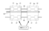
特に、電力と駆動制御信号は互いに分離された状態で可動テーブル2の駆動手段4に供給されるので、例えば図8に示すように、ベース部1上の軌道レール30に対して複数の可動テーブル2a,2bを組み付けた場合であっても、非接触給電手段の一次側部材は共用しながらも、個々の可動テーブル2a,2bの走行を別々に制御することができ、このアクチュエータを搬送装置等の用途に用いる場合に非常に有益である。また、この場合、無線送信部62と無線受信部70との間の送信電波の周波数を可動テーブル毎に異ならせて設定することにより、一つの制御ユニット6を用いて複数の可動テーブル2a,2bを制御することも可能となる。
In particular, the electric power and the drive control signal are supplied to the driving means 4 of the movable table 2 in a state where they are separated from each other, so that, for example, as shown in FIG. Even when 2a and 2b are assembled, the primary side member of the non-contact power feeding means can be shared, but the traveling of the individual movable tables 2a and 2b can be controlled separately. This is very useful when used in various applications. Further, in this case, by setting the frequency of the transmission radio wave between the
尚、以上説明してきたワイヤレスアクチュエータの例ではベース部1に対して可動テーブル2が直線往復運動を行うものであったが、これに限定されるものではなく、可動テーブル2がベース部1上を曲線の移動経路に沿って走行し、あるいは直線と曲線とが混在する移動経路に沿って走行するものであっても差し支えない。
In the example of the wireless actuator described above, the movable table 2 performs a linear reciprocating motion with respect to the
また、図6に示したブロック図では、非接触給電手段5の二次側部材51に発生した起電力を整流回路52によって直流電圧に変換した後、駆動手段4のドライバ回路41や無線受信部70に対して直接供給しているが、図9に示すように、可動テーブル2にバックアップ用の二次電池9を搭載するように構成することもできる。すなわち、前記整流回路52に対して二次電池9を接続し、この二次電池9を非接触給電手段5によって移送された電力で充電する一方、かかる二次電池9からも駆動手段4のドライバ回路41や無線受信部70に対して直流電圧を印加できるように構成する。このようにバックアップ用の二次電池9を可動テーブル2に搭載し、それを常に非接触給電手段5によって充電するように構成すれば、例えば不意の停電によってベース部1から可動テーブル2への電力の移送が断たれても、駆動手段4に電力を供給し続けることができ、可動テーブル2をベース部1上の初期位置に退避させる等の処置を自動的に行わせることが可能となる。
In the block diagram shown in FIG. 6, after the electromotive force generated in the
一方、図10は本発明のワイヤレスアクチュエータの第二の実施形態を示すものである。前述した第一の実施形態では、非接触給電手段5の一次側部材50となるコイルを軌道レール30に沿ってベース部1に配列し、可動テーブル2がベース部1上を移動した場合であっても、可動テーブル2に搭載した二次側部材51が常に一次側部材50と対向するように構成した。これにより、第一の実施形態では、可動テーブル2がベース部1上の何処を走行していても、ベース部1側から可動テーブル2側へ電力を移送することが可能である。しかし、軌道レール30に沿って一次側部材50を連続的に配列したのでは、可動テーブル2の移動経路が長い場合にベース部1の製作に手間がかかり、コスト高を招くといった弊害がある。
On the other hand, FIG. 10 shows a second embodiment of the wireless actuator of the present invention. In the first embodiment described above, the coil serving as the
そこで、図10に示す第二の実施形態では、可動テーブル2に二次電池9を搭載すると共に、非接触給電手段5の一次側部材50をベース部1上の一乃至複数の特定箇所にのみ設け、かかる特定箇所に可動テーブル2が停止した場合に前記二次電池9を充電するように構成している。それ以外の構成は前記第一の実施形態と同一である。すなわち、可動テーブル2に対する搭載物は図9を用いて説明した例と全く同一である。
Therefore, in the second embodiment shown in FIG. 10, the secondary battery 9 is mounted on the movable table 2, and the
図10に示すように、ベース部1上における可動テーブル2の充電位置P0に対応し、かかるベース部1上には非接触給電手段5の一次側部材50が設けられている。このため、可動テーブル2が充電位置P0に設定されている最中は、ベース部1に設けられた一次側部材50と可動テーブル2に搭載された二次側部材51とが互いに対向しており、一次側部材50に交流電圧を印加することで二次側部材51に起電力が発生し、整流回路52を介して二次電池9に直流電圧を印加することができる。これにより、可動テーブル2が充電位置P0に停止している間は二次電池9に対して充電を行うことが可能となる。そして、このようにして二次電池9が充電されれば、二次電池9から駆動手段4のドライバ回路41及び無線受信部70に対して電力を供給することにより、可動テーブル2を軌道レール30に沿って充電位置P0から他の位置へ走行させることができる。As shown in FIG. 10, the
例えば、工作機械や搬送装置におけるアクチュエータの使用方法としては、前記可動テーブル2に特定のプロセスからなるジョブを繰り返し行わせる場合が殆どであり、前後するジョブの間では可動テーブル2が原点である初期位置に設定し直されることが多い。また、ジョブの最中であっても、可動テーブル2上に積まれた搬送物に対して作業が行われるため、かかる可動テーブル2が特定の位置に短時間だけ停止する場合も多々ある。このため、そのように可動テーブル2がベース部1上で頻繁に停止する一乃至複数の位置を前述の充電位置P0とすれば、可動テーブル2に搭載した二次電池9を頻繁に充電することができ、二次電池から供給される電力のみをもって可動テーブル2をベース部1上で走行させ続けることが可能である。For example, as a method of using an actuator in a machine tool or a conveyance device, the movable table 2 is often repeatedly executed with a job consisting of a specific process. Often reset to position. Even during the job, since the work is carried out on the transported objects loaded on the movable table 2, the movable table 2 often stops at a specific position for a short time. For this reason, if one or a plurality of positions where the movable table 2 frequently stops on the
そして、このように構成された第二の実施形態のワイヤレスアクチュエータによれば、非接触給電手段5の一次側部材50をベース部1上の一乃至複数箇所にのみ設けることで、可動テーブル2を走行させることができるので、前述の第一の実施形態のアクチュエータと比較してベース部1の加工が容易となり、低コストで製作することが可能となる。
And according to the wireless actuator of 2nd Embodiment comprised in this way, by providing the
次に、本発明のワイヤレスアクチュエータの第三の実施形態について説明する。前述した第一の実施形態では可動テーブル2の走行位置を検出するポジションセンサ63をベース部1の一乃至複数箇所に設けたが、そのような構成だと、可動テーブル2の走行位置を断続的にしか把握することができず、可動テーブル2にはポジションセンサ63の設置位置に対応した一種類のジョブしか行わせることができない。すなわち、走行プロセスの異なるジョブを可動テーブル2に行わせるためには、予めポジションセンサ63の設置位置を変更する段取りが必要となってしまう。
Next, a third embodiment of the wireless actuator of the present invention will be described. In the first embodiment described above, the
このような問題点に鑑み、これから説明する第三の実施形態のアクチュエータでは、図11に示すように、ベース部1上にスケール64を設ける一方、可動テーブル2には前記スケール64を読み取るエンコーダ65を搭載し、エンコーダ65の出力信号を制御ユニット6に無線送信するように構成した。
In view of such a problem, in the actuator of the third embodiment to be described below, as shown in FIG. 11, a
前記スケール64は光学スケール、磁気スケール等のように所定のピッチで繰り返しラダーパターンが連続するものであれば良く、軌道レール30に沿ってベース部1上に固定的に設けられている。前記エンコーダ65は可動テーブル2に固定されており、かかる可動テーブル2の移動に伴って前記スケール64に形成されたラダーパターンを読み取り、かかるラダーパターンに対応したパルス信号を出力する。
The
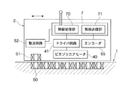
図12は可動テーブル2の搭載物の構成を示すブロック図である。前記エンコーダ65は可動テーブル2に搭載されているが、このエンコーダ65の出力信号は制御ユニット6のMCU61が駆動制御信号を生成する際に必要とされる。このため、可動テーブル2には無線送信部71が設けられ、エンコーダ65の出力信号はこの無線送信部71によって制御ユニット6へ送信されるようになっている。また、前記無線送信部71は前述の無線受信部70と相まって可動テーブル2上で送受信機7を構成している。非接触給電手段5の整流回路52によって形成された直流電圧は前記送受信機7に印加され、それによって送受信機7に含まれる無線送信部71及び無線受信部70が動作を行う。可動テーブル2の搭載物のその他の構成は前述の第一の実施形態と同一である。すなわち、非接触給電手段5の二次側部材51に発生した起電力が整流回路52によって直流電圧に変換され、この直流電圧がドライバ回路41に印加される。ドライバ回路41は無線受信部70から駆動制御信号を受け取り、ピエゾリニアモータ40に対して適宜電圧を印加する。それにより、ピエゾリニアモータ40が動作し、可動テーブル2がベース部1上で軌道レール30に沿って推進される。
FIG. 12 is a block diagram showing a configuration of a load on the movable table 2. The
一方、図13は第三の実施形態における制御ユニット6aを示すブロック図である。この制御ユニット6aは無線受信部66を備え、可動テーブル2から無線送信されるエンコーダ65の出力信号を受信することができるようになっている。前記無線受信部66は前述の無線送信部62と相まって制御ユニット2内で送受信機67を構成している。無線受信部66で受信されたエンコーダ65の出力信号はMCU61に読み込まれる。エンコーダ65の出力信号はスケール64のラダーパターンに対応したパルス信号であるから、MCU61は該パルス信号をカウントすることにより、可動テーブル2の走行距離、走行速度を把握することができる。また、前述の第一の実施形態と同様に、MCU61に対してはユーザインターフェース60から走行指示情報が入力され、MCU61は無線受信部66及びユーザインターフェース60からの入力情報に基づいて駆動制御信号を生成する。そして、MCU61で生成された駆動制御信号は無線送信部62を介して可動テーブル2の無線受信部70へ送信される。
On the other hand, FIG. 13 is a block diagram showing a
これにより、可動テーブル2の駆動手段4の動作が制御され、何ら可動テーブル2に電力ケーブルや信号ケーブル等のケーブル類を接続することなく、走行指示情報に基づいて可動テーブル2をベース部1上で走行させることが可能となる。また、可動テーブル2の走行距離及び走行速度を示す情報が該可動テーブル2から制御ユニット6aへ無線送信されるので、制御ユニット6aに入力する走行指示情報を変更すれば、ベース部1上における可動テーブル2の動きを自由に変更することができる。このため、ベース部1や可動テーブル2に対して何ら作業を行うことなく、走行プロセスの異なる数種類のジョブに対して当該アクチュエータを柔軟に対応させることが可能となる。
As a result, the operation of the driving means 4 of the movable table 2 is controlled, and the movable table 2 is placed on the
図14は、本発明のワイヤレスアクチュエータの第四の実施形態を示すものである。前述した各実施形態では、ベース部1上に配設されたリニアガイド3を用いて可動テーブル2の運動を支承し、かかる可動テーブル2及びベース部1に対して駆動手段4、無線受信部70、非接触給電手段5を搭載した。しかし、この第四の実施形態ではワイヤレスアクチュエータの更なる小型化を図るため、軌道レール80とスライド部材81から構成されるリニアガイド8そのものに前記駆動手段4、無線受信部70、非接触給電手段5を組み込んだ。すなわち、リニアガイド8のスライド部材81が本発明における可動テーブルに、リニアガイド8の軌道レール80が本発明におけるベース部に相当している。
FIG. 14 shows a fourth embodiment of the wireless actuator of the present invention. In each of the above-described embodiments, the movement of the movable table 2 is supported using the
図14に示すように、軌道レール80はその両側面にボール転走面82を備え、スライド部材81は前記ボール転走面82を転走する多数のボール(図示せず)を介して該軌道レール80に組み付けられている。これにより、スライド部材81は軌道レール80の長手方向に沿って自在に移動可能となっている。前記軌道レール80の上面における幅方向の中央には長手方向に連続する溝が形成され、かかる溝の内部には非接触給電手段5の一次側部材50を構成する多数のコイルが一列に配列されている。一方、スライド部材81には前記一次側部材50と対向する位置に非接触給電手段の二次側部材51となるコイルが配設されており、スライド部材81が軌道レール80に沿って移動しても、かかる二次側部材51が一次側部材50と対向し続けるようになっている。また、スライド部材81には駆動手段4としてピエゾリニアモータ40及びそのドライバ回路41が搭載されており、かかるピエゾリニアモータ4の駆動脚の先端は軌道レール80の上面に接触している。更に、スライド部材81には、二次側部材51で発生した起電力を直流電圧に変換する整流回路52、制御ユニット6から送信された駆動制御信号を受信して前記ドライバ回路41へ送出する無線受信部70が搭載されている。すなわち、スライド部材81に搭載される要素は、図5において可動テーブル2に搭載されている要素と同一である。
As shown in FIG. 14, the
尚、可動テーブル2の無線受信部70に対して駆動制御信号を送信する制御ユニット6の構成は前記第一の実施形態と同一であり、その詳細な説明は省略する。
The configuration of the
従って、この第四の実施形態のワイヤレスアクチュエータでは、前記第一の実施形態と同様、制御ユニット6に対して可動テーブルの走行指示情報を入力することにより、リニアガイド8のスライド部材81が軌道レール80上を前記走行指示情報に従って往復動することになる。しかし、総ての要素がリニアガイド8の軌道レール80及びスライド部材81に組み込まれているので、前記第一の実施形態のワイヤレスアクチュエータよりも極めてコンパクトに構成されており、例えば、各種検査装置等のように比較的軽荷重の用途に使用する場合には、かかる装置の小型化に資することができる。
Therefore, in the wireless actuator of the fourth embodiment, as in the first embodiment, the
また、このようにリニアガイドそのものをワイヤレスアクチュエータとして構成する場合、図1乃至図13を用いて説明してきた総ての実施形態はそのままリニアガイドに適用することができる。すなわち、可動テーブル2はスライド部材に、ベース部1は軌道レールに置き換えて構成することができる。いずれの場合であっても、極めてコンパクトなワイヤレスアクチュエータを提供することが可能となる。
When the linear guide itself is configured as a wireless actuator in this manner, all the embodiments described with reference to FIGS. 1 to 13 can be applied to the linear guide as they are. In other words, the movable table 2 can be replaced with a slide member, and the
Claims (6)
前記軌道レールには長手方向に連続する溝が形成され、かかる溝の内部には前記非接触給電手段の一次側部材が組み込まれる一方、前記駆動手段、無線受信部及び非接触給電手段の二次側部材は前記スライド部材に組み込まれ、
前記非接触給電手段の一次側部材及び二次側部材は、夫々、互いに対向して設けられたコイル部材からなり、電磁誘導方式により前記一次側部材から二次側部材に電力を供給することを特徴とするワイヤレスアクチュエータ。A movable table including a base portion including a track rail disposed along a predetermined path, a slide member assembled to the track rail via a plurality of balls, and movable along the track rail, and the movable table Mounted on the movable table and traveling the movable table with respect to the track rail, a wireless receiver mounted on the movable table and receiving a drive control signal for the drive means, and a drive control signal for the drive means And a control unit that wirelessly transmits to the wireless reception unit, a primary side member provided on the base portion, and a secondary side member provided on the movable table, and driving means mounted on the movable table and wireless reception A non-contact power supply means for supplying power from the base part side to the part,
A groove continuous in the longitudinal direction is formed in the track rail, and a primary side member of the non-contact power feeding unit is incorporated in the groove, while a secondary of the driving unit, the wireless receiver, and the non-contact power feeding unit Side members are incorporated into the slide member,
The primary side member and the secondary side member of the non-contact power feeding unit are respectively composed of coil members provided to face each other, and supply power from the primary side member to the secondary side member by an electromagnetic induction method. Features wireless actuator.
Priority Applications (1)
| Application Number | Priority Date | Filing Date | Title |
|---|---|---|---|
| JP2007547886A JP4975640B2 (en) | 2005-11-30 | 2006-11-13 | Wireless actuator |
Applications Claiming Priority (4)
| Application Number | Priority Date | Filing Date | Title |
|---|---|---|---|
| JP2005345547 | 2005-11-30 | ||
| JP2005345547 | 2005-11-30 | ||
| JP2007547886A JP4975640B2 (en) | 2005-11-30 | 2006-11-13 | Wireless actuator |
| PCT/JP2006/322543 WO2007063693A1 (en) | 2005-11-30 | 2006-11-13 | Wireless actuator |
Publications (2)
| Publication Number | Publication Date |
|---|---|
| JPWO2007063693A1 JPWO2007063693A1 (en) | 2009-05-07 |
| JP4975640B2 true JP4975640B2 (en) | 2012-07-11 |
Family
ID=38092029
Family Applications (1)
| Application Number | Title | Priority Date | Filing Date |
|---|---|---|---|
| JP2007547886A Expired - Fee Related JP4975640B2 (en) | 2005-11-30 | 2006-11-13 | Wireless actuator |
Country Status (5)
| Country | Link |
|---|---|
| US (1) | US8141499B2 (en) |
| EP (1) | EP1956705B1 (en) |
| JP (1) | JP4975640B2 (en) |
| CN (1) | CN101326706A (en) |
| WO (1) | WO2007063693A1 (en) |
Cited By (3)
| Publication number | Priority date | Publication date | Assignee | Title |
|---|---|---|---|---|
| US8946054B2 (en) | 2013-04-19 | 2015-02-03 | International Business Machines Corporation | Crack control for substrate separation |
| KR102204169B1 (en) * | 2019-09-09 | 2021-01-18 | 하이윈 테크놀로지스 코포레이션 | Linear transmission device with capability of wireless power supply |
| US11142082B2 (en) | 2019-08-07 | 2021-10-12 | Hiwin Technologies Corp. | Linear transmission device with capability of wireless power supply |
Families Citing this family (45)
| Publication number | Priority date | Publication date | Assignee | Title |
|---|---|---|---|---|
| JP5309533B2 (en) * | 2007-11-13 | 2013-10-09 | 村田機械株式会社 | Power supply system |
| JP5335225B2 (en) * | 2007-11-30 | 2013-11-06 | 三重電子株式会社 | Guide device |
| DE102008016684B4 (en) | 2008-04-01 | 2015-10-08 | Minebea Co., Ltd. | Electromechanical motor |
| DE102008026770A1 (en) * | 2008-06-04 | 2009-12-10 | Robert Bosch Gmbh | Linear movement device, has friction surface formed at ceramic, longitudinally-extended friction lining that is formed from guide rail, where friction lining is supported at base of guide rail over whole length of guide rail |
| GB2463693A (en) * | 2008-09-19 | 2010-03-24 | Bombardier Transp Gmbh | A system for transferring electric energy to a vehicle |
| JP5614058B2 (en) * | 2009-03-04 | 2014-10-29 | セイコーエプソン株式会社 | Fluid ejection device |
| KR20110050831A (en) * | 2009-11-09 | 2011-05-17 | 삼성전자주식회사 | Apparatus and method for supporting contactless charging in battery charging systems |
| EP2599186B1 (en) * | 2010-07-29 | 2016-09-14 | ATS Automation Tooling Systems Inc. | System and method for providing power to a moving element |
| JP5579581B2 (en) | 2010-11-17 | 2014-08-27 | 富士機械製造株式会社 | Reciprocating device |
| CN102075017B (en) * | 2011-02-18 | 2014-01-15 | 中国科学院电工研究所 | A mobile non-contact uninterrupted power supply device |
| DE102011014521A1 (en) | 2011-03-18 | 2012-09-20 | Georg Duschl-Graw | Device for inductive transmission of electrical energy |
| JP2013070477A (en) * | 2011-09-21 | 2013-04-18 | Panasonic Corp | Non-contact power supply system |
| AT512028B1 (en) * | 2011-10-13 | 2015-06-15 | Avl List Gmbh | ELECTRIC ENERGY STORAGE |
| CN102497130B (en) * | 2011-12-20 | 2015-01-07 | 哈尔滨工业大学深圳研究生院 | Linear ultrasonic motor |
| JP6058003B2 (en) * | 2012-07-11 | 2017-01-11 | 富士機械製造株式会社 | Electrostatic coupling type non-contact power feeding device |
| US9089207B2 (en) * | 2012-09-05 | 2015-07-28 | Nucraft Furniture Company | Conference table with movable table top and ganging capability |
| CN103659791B (en) * | 2012-09-26 | 2016-03-02 | 电装波动株式会社 | Wireless power supply and possess the direct-driving type system of this device |
| CN202918004U (en) * | 2012-10-15 | 2013-05-01 | 东莞富强电子有限公司 | Wireless charger |
| CN102931735B (en) * | 2012-11-07 | 2015-03-25 | 湖南银河电气有限公司 | Non-contact power supply system and method for mobile device moving along track |
| DE102012022146A1 (en) * | 2012-11-12 | 2014-05-15 | Physik Instrumente (Pi) Gmbh & Co. Kg | Ultrasonic actuator for a linear ultrasonic motor and linear ultrasonic motor with an ultrasonic actuator |
| US9050896B2 (en) * | 2012-11-22 | 2015-06-09 | Paramount Pictures Corporation | Regenerative energy system for ground transportation vehicles |
| DE102012224367A1 (en) * | 2012-12-27 | 2014-07-03 | Robert Bosch Gmbh | linear actuator |
| DE102013223289A1 (en) * | 2013-11-15 | 2015-05-21 | Robert Bosch Gmbh | Guide rail with closed reference holes |
| EP3137854B1 (en) * | 2014-04-04 | 2018-10-17 | NTN-SNR Roulements | Method for transmitting information from a mobile rig along a fixed path, associated transmission device and facility |
| USD835492S1 (en) * | 2015-02-24 | 2018-12-11 | Thk Co., Ltd. | Slide rail |
| US10625612B2 (en) * | 2015-04-15 | 2020-04-21 | Ford Global Technologies, Llc | Deployable vehicle inductive charging assembly |
| US10000134B2 (en) * | 2016-03-28 | 2018-06-19 | Denso International America, Inc. | Wireless charging system for charging vehicular battery |
| JP2018120358A (en) * | 2017-01-24 | 2018-08-02 | Thk株式会社 | Work transportation control system and motion guide device |
| WO2018161016A1 (en) | 2017-03-02 | 2018-09-07 | Discovery Technology International, Inc. | Linear piezoelectric actuator on rail system |
| DE102017206584A1 (en) * | 2017-04-19 | 2018-10-25 | Robert Bosch Gmbh | Linear motion device with sensor holder |
| US10994953B2 (en) | 2017-05-02 | 2021-05-04 | Laitram, L.L.C. | Tray conveyor driven by brushless DC motor |
| FR3067528B1 (en) | 2017-06-13 | 2020-10-09 | Continental Automotive France | REMOTE POWER SUPPLY, POSITION SENSOR AND WIRELESS COMMUNICATION DEVICE FOR DOOR DEPLOYING HANDLES |
| EP3642142A4 (en) | 2017-06-19 | 2021-03-17 | Laitram, L.L.C. | Monorail tray conveyor |
| DE102017122754A1 (en) * | 2017-09-29 | 2019-04-04 | MAX-PLANCK-Gesellschaft zur Förderung der Wissenschaften e.V. | Device and vacuum chamber |
| JP7007875B2 (en) * | 2017-11-24 | 2022-01-25 | 国立大学法人豊橋技術科学大学 | High frequency oscillator and wireless power supply device using this |
| KR101997869B1 (en) * | 2017-12-28 | 2019-07-08 | 주식회사 디에스시동탄 | Wireless swivel device for seat |
| CN109634180B (en) * | 2018-12-19 | 2021-08-27 | 广州励丰文化科技股份有限公司 | Art device track operation control system of performance place |
| DE102019123392B3 (en) * | 2019-09-02 | 2021-02-11 | Hiwin Technologies Corp. | LINEAR TRANSMISSION DEVICE WITH WIRELESS POWER SUPPLY |
| US11251643B2 (en) * | 2019-09-05 | 2022-02-15 | Hanwan ZHONG | Linear actuator for wireless charging |
| CN110973819A (en) * | 2019-12-18 | 2020-04-10 | 联想(北京)有限公司 | Wireless charging table and wireless charging method thereof |
| CN113154191B (en) * | 2020-01-22 | 2023-02-03 | 苏州佳世达电通有限公司 | Support frame and display device using same |
| US12291156B2 (en) * | 2020-03-17 | 2025-05-06 | Ts Tech Co., Ltd. | Attachment structure for functional component and interior member |
| US11458636B2 (en) | 2020-05-19 | 2022-10-04 | Dong Ouyang | Wirelessly powered and controlled robotic apparatus |
| US11642995B1 (en) | 2020-07-10 | 2023-05-09 | Apple Inc. | Movable support surfaces |
| TWI891307B (en) * | 2024-03-28 | 2025-07-21 | 全球傳動科技股份有限公司 | Intelligent linear motion device with wireless charging module |
Citations (4)
| Publication number | Priority date | Publication date | Assignee | Title |
|---|---|---|---|---|
| JPH08140331A (en) * | 1994-11-08 | 1996-05-31 | Daifuku Co Ltd | Conveyer installation making use of linear motor |
| JPH1115530A (en) * | 1997-06-24 | 1999-01-22 | Tokyo Technol:Kk | Stage driving electric control system for electron beam plotting device |
| JP2002136159A (en) * | 2000-10-24 | 2002-05-10 | Taiheiyo Cement Corp | Feeding device and feeding mechanism |
| JP2004357393A (en) * | 2003-05-28 | 2004-12-16 | Nsk Ltd | Piezoelectric actuator and positioning device |
Family Cites Families (30)
| Publication number | Priority date | Publication date | Assignee | Title |
|---|---|---|---|---|
| JPH0719693Y2 (en) * | 1990-04-27 | 1995-05-10 | エヌティエヌ株式会社 | Moving table |
| JPH05177487A (en) * | 1991-12-24 | 1993-07-20 | Nippon Thompson Co Ltd | Drive |
| JPH05177488A (en) * | 1991-12-25 | 1993-07-20 | Nippon Thompson Co Ltd | Drive |
| US5329825A (en) * | 1992-11-25 | 1994-07-19 | Eastman Kodak Company | Precision moving stage |
| US5575565A (en) * | 1993-11-08 | 1996-11-19 | Nippon Thompson Co., Ltd. | Rolling guide unit |
| DE69406263T2 (en) * | 1994-01-14 | 1998-04-30 | Bayer Ag | Carrier for a self-propelled linear engine |
| US5623853A (en) * | 1994-10-19 | 1997-04-29 | Nikon Precision Inc. | Precision motion stage with single guide beam and follower stage |
| US5533844A (en) * | 1994-11-15 | 1996-07-09 | Ekleberry; Donald A. | Travelling platen with extended axis |
| JP3398238B2 (en) * | 1994-11-17 | 2003-04-21 | 日本トムソン株式会社 | Stopping device and rolling guide unit having the same |
| US5681116A (en) * | 1996-12-17 | 1997-10-28 | Lin; Chin-Chih | Sliding track assembly |
| JP2000159306A (en) | 1998-11-24 | 2000-06-13 | Toyota Autom Loom Works Ltd | Cargo transfer device |
| FR2808186B1 (en) * | 2000-04-27 | 2003-02-21 | Alm | OPERATING TABLE CONTROL SYSTEM AND OPERATING TABLE COMPRISING SUCH A SYSTEM |
| FR2812807B1 (en) * | 2000-08-08 | 2002-11-15 | Alm | OPERATING TABLE, IN PARTICULAR FOR SURGICAL INTERVENTIONS |
| WO2002043526A2 (en) * | 2000-12-01 | 2002-06-06 | Larson John E | Unaligned multiple-column height adjustable pedestals for tables and chairs that tilt and slide |
| US6978499B2 (en) * | 2001-05-25 | 2005-12-27 | Hill-Rom Services, Inc. | Architectural bed docking apparatus |
| US6857712B1 (en) * | 2002-04-04 | 2005-02-22 | Forecast Consoles, Inc. | Multi-media workstation having a master rail system |
| AU2003254689A1 (en) * | 2002-09-03 | 2004-03-29 | Vitra Patente Ag | Table, especially conference and office table |
| US20040083933A1 (en) * | 2002-09-06 | 2004-05-06 | Baric Thomas J. | Linear table and simplified assembly method |
| CA2422341A1 (en) * | 2003-03-17 | 2004-09-17 | Hirofumi Tamai | Integrated wireless linear motor |
| JP4259978B2 (en) * | 2003-03-25 | 2009-04-30 | Thk株式会社 | Linear motor actuator |
| US7106014B1 (en) * | 2003-04-07 | 2006-09-12 | Krueger International, Inc. | Lectern |
| US7322653B2 (en) * | 2003-06-13 | 2008-01-29 | Vlad Dragusin | Integrated videogaming and computer workstation |
| US20050217540A1 (en) * | 2004-03-31 | 2005-10-06 | Novak Daniel A | Emergency dispatch workstation |
| US7059370B2 (en) * | 2004-05-04 | 2006-06-13 | Wang Tien Wang | Extension structure for table saw |
| US7677678B2 (en) * | 2004-06-09 | 2010-03-16 | Spectrum Industries Inc. | Wheelchair accommodating system |
| US8276873B2 (en) * | 2004-10-22 | 2012-10-02 | Newport Corporation | Instrumented platform for vibration-sensitive equipment |
| JP4678204B2 (en) * | 2005-02-18 | 2011-04-27 | 横河電機株式会社 | XY stage |
| US20070227409A1 (en) * | 2006-03-29 | 2007-10-04 | Ching-Shan Chu | UPS uninterruptible power supply mobile computer table structure |
| US20080250985A1 (en) * | 2007-03-14 | 2008-10-16 | Hall David W | Multifunction Furniture |
| US20080245279A1 (en) * | 2007-04-04 | 2008-10-09 | Pan Chun Ming | Automatic Continuously Height Adjustable Table |
-
2006
- 2006-11-13 CN CNA2006800451048A patent/CN101326706A/en active Pending
- 2006-11-13 JP JP2007547886A patent/JP4975640B2/en not_active Expired - Fee Related
- 2006-11-13 EP EP06832555.4A patent/EP1956705B1/en not_active Ceased
- 2006-11-13 US US12/095,012 patent/US8141499B2/en not_active Expired - Fee Related
- 2006-11-13 WO PCT/JP2006/322543 patent/WO2007063693A1/en not_active Ceased
Patent Citations (4)
| Publication number | Priority date | Publication date | Assignee | Title |
|---|---|---|---|---|
| JPH08140331A (en) * | 1994-11-08 | 1996-05-31 | Daifuku Co Ltd | Conveyer installation making use of linear motor |
| JPH1115530A (en) * | 1997-06-24 | 1999-01-22 | Tokyo Technol:Kk | Stage driving electric control system for electron beam plotting device |
| JP2002136159A (en) * | 2000-10-24 | 2002-05-10 | Taiheiyo Cement Corp | Feeding device and feeding mechanism |
| JP2004357393A (en) * | 2003-05-28 | 2004-12-16 | Nsk Ltd | Piezoelectric actuator and positioning device |
Cited By (3)
| Publication number | Priority date | Publication date | Assignee | Title |
|---|---|---|---|---|
| US8946054B2 (en) | 2013-04-19 | 2015-02-03 | International Business Machines Corporation | Crack control for substrate separation |
| US11142082B2 (en) | 2019-08-07 | 2021-10-12 | Hiwin Technologies Corp. | Linear transmission device with capability of wireless power supply |
| KR102204169B1 (en) * | 2019-09-09 | 2021-01-18 | 하이윈 테크놀로지스 코포레이션 | Linear transmission device with capability of wireless power supply |
Also Published As
| Publication number | Publication date |
|---|---|
| CN101326706A (en) | 2008-12-17 |
| US20100031856A1 (en) | 2010-02-11 |
| JPWO2007063693A1 (en) | 2009-05-07 |
| EP1956705A1 (en) | 2008-08-13 |
| EP1956705A4 (en) | 2012-08-08 |
| US8141499B2 (en) | 2012-03-27 |
| WO2007063693A1 (en) | 2007-06-07 |
| EP1956705B1 (en) | 2014-10-01 |
Similar Documents
| Publication | Publication Date | Title |
|---|---|---|
| JP4975640B2 (en) | Wireless actuator | |
| TWI538381B (en) | Discrete configuration linear motor system | |
| KR102164594B1 (en) | Linear motor and controlling system of the same | |
| JP6335603B2 (en) | Carriage transfer system | |
| KR101480785B1 (en) | Conveyance system | |
| US8794426B2 (en) | Pallet-based position adjustment system and method | |
| JP6521772B2 (en) | Transport system and control method thereof, and carriage and control method thereof | |
| JP6704705B2 (en) | Movable magnet type linear motor control system and control method thereof | |
| CN103286782B (en) | The flexible tracing-positioning system of a kind of robot and method for tracking and positioning | |
| WO2013069203A1 (en) | Linear conveyor | |
| WO2012066862A1 (en) | Reciprocating device | |
| EP2633951A1 (en) | Unit configuration type machine tool, transfer device, working equipment | |
| JPH08275500A (en) | Linear motor | |
| JP2020129854A (en) | Carrier and carrier system | |
| CN108481746A (en) | A kind of increasing material manufacturing equipment based on air supporting principle | |
| KR20150109664A (en) | Contactless and Wireless Gantry Robot | |
| JP3465786B2 (en) | Linear actuator | |
| JP2008216217A (en) | Positioning stage | |
| JP2023008391A (en) | Control system and method for controlling control system | |
| JP4636034B2 (en) | Control device for movable table and movable table device including the same | |
| JP2010159146A (en) | Carrying device | |
| JP2018074829A (en) | Transport system | |
| SU965702A1 (en) | Apparatus for assembling parts | |
| KR20220154305A (en) | Gantry system and control method thereof | |
| JP4976178B2 (en) | Drive guidance system and malfunction detection method |
Legal Events
| Date | Code | Title | Description |
|---|---|---|---|
| A131 | Notification of reasons for refusal |
Free format text: JAPANESE INTERMEDIATE CODE: A131 Effective date: 20110517 |
|
| A521 | Request for written amendment filed |
Free format text: JAPANESE INTERMEDIATE CODE: A523 Effective date: 20110719 |
|
| A02 | Decision of refusal |
Free format text: JAPANESE INTERMEDIATE CODE: A02 Effective date: 20111101 |
|
| A521 | Request for written amendment filed |
Free format text: JAPANESE INTERMEDIATE CODE: A523 Effective date: 20120127 |
|
| A911 | Transfer to examiner for re-examination before appeal (zenchi) |
Free format text: JAPANESE INTERMEDIATE CODE: A911 Effective date: 20120203 |
|
| TRDD | Decision of grant or rejection written | ||
| A01 | Written decision to grant a patent or to grant a registration (utility model) |
Free format text: JAPANESE INTERMEDIATE CODE: A01 Effective date: 20120410 |
|
| A01 | Written decision to grant a patent or to grant a registration (utility model) |
Free format text: JAPANESE INTERMEDIATE CODE: A01 |
|
| A61 | First payment of annual fees (during grant procedure) |
Free format text: JAPANESE INTERMEDIATE CODE: A61 Effective date: 20120411 |
|
| R150 | Certificate of patent or registration of utility model |
Ref document number: 4975640 Country of ref document: JP Free format text: JAPANESE INTERMEDIATE CODE: R150 Free format text: JAPANESE INTERMEDIATE CODE: R150 |
|
| FPAY | Renewal fee payment (event date is renewal date of database) |
Free format text: PAYMENT UNTIL: 20150420 Year of fee payment: 3 |
|
| R250 | Receipt of annual fees |
Free format text: JAPANESE INTERMEDIATE CODE: R250 |
|
| R250 | Receipt of annual fees |
Free format text: JAPANESE INTERMEDIATE CODE: R250 |
|
| R250 | Receipt of annual fees |
Free format text: JAPANESE INTERMEDIATE CODE: R250 |
|
| R250 | Receipt of annual fees |
Free format text: JAPANESE INTERMEDIATE CODE: R250 |
|
| LAPS | Cancellation because of no payment of annual fees |