JP4876492B2 - Parts assembly method and handling robot used in the method - Google Patents
Parts assembly method and handling robot used in the method Download PDFInfo
- Publication number
- JP4876492B2 JP4876492B2 JP2005255910A JP2005255910A JP4876492B2 JP 4876492 B2 JP4876492 B2 JP 4876492B2 JP 2005255910 A JP2005255910 A JP 2005255910A JP 2005255910 A JP2005255910 A JP 2005255910A JP 4876492 B2 JP4876492 B2 JP 4876492B2
- Authority
- JP
- Japan
- Prior art keywords
- panel
- temporary
- jig
- welding
- handling robot
- Prior art date
- Legal status (The legal status is an assumption and is not a legal conclusion. Google has not performed a legal analysis and makes no representation as to the accuracy of the status listed.)
- Expired - Fee Related
Links
Images


Landscapes
- Automatic Assembly (AREA)
- Automobile Manufacture Line, Endless Track Vehicle, Trailer (AREA)
- Resistance Welding (AREA)
Description
本発明は、自動車用の各種パネル類に代表されるように二つ以上のパネル要素をもって構成されることになるパネル部品の部品組立方法とその方法に用いるハンドリングロボットに関するものである。 The present invention relates to a method for assembling a panel component that is constituted by two or more panel elements as represented by various types of panels for automobiles, and a handling robot used in the method.
この種の部品組み立てに関する技術として例えば特許文献1に記載の技術が知られている。
As a technique related to this type of component assembly, for example, a technique described in
この特許文献1に記載の技術では、複数の単品パネル要素の集合体をもって構成されることになるパネル部品の溶接組み立てを行うにあたり、直交3軸の動作自由度に加えてロケートピンによる位置決め機能をクランプ機能とを有するロケータ装置を多数配置して組立治具とし、この組立治具に対してパネル部品を構成することになる単品パネル要素を同時投入して、個々のロケータ装置にてそれぞれの単品パネル要素を位置決めクランプする一方、特定のロケータ装置のアプローチ動作にて単品パネル要素相互の相対位置決めを行った上で、溶接用ロボットが持つスポット溶接ガンにてスポット溶接を施して組み立てを行うようになっている。
このような従来の技術では、組立治具そのものが高機能であるために複数種類のパネル部品の組み立てを行うことができ、その汎用性に優れる一方、設備費が高価となるだけでなく、次に列挙するような問題点がある
(a)多数のロケータ装置の並設に伴う錯綜化によって構造も著しく複雑となり、例えば生産台数の変動により設備を移設したい場合でも簡単に移設することができない。
In such a conventional technique, the assembly jig itself has a high function, so that it is possible to assemble a plurality of types of panel parts. (A) The structure is remarkably complicated due to the complication associated with the parallel arrangement of a large number of locator devices. For example, even if it is desired to relocate equipment due to fluctuations in the number of production, it cannot be easily relocated.
(b)サイクルタイム内において、投入した単品パネル要素同士の相対位置決めに要する時間の割合が相対的に大きく、溶接用ロボットの稼働可能時間が短くなる。 (B) Within the cycle time, the ratio of the time required for relative positioning of the supplied single panel elements is relatively large, and the operating time of the welding robot is shortened.
(c)設備の錯綜化に伴い特に狭隘なスペースへのスポット溶接ガンのアクセス性が悪く、必要な打点位置全てにスポット溶接を施すことができないことがある。 (C) With the complexity of the equipment, the accessibility of the spot welding gun to a particularly narrow space is poor, and spot welding may not be performed at all necessary spot positions.
(d)上記の(b)および(c)の傾向が顕著となる場合には、別途後工程でいわゆる増打ちを施さなければならず、工程数の増加が余儀なくされる。 (D) When the above trends (b) and (c) become prominent, so-called additional hitting must be performed in a separate post process, and the number of processes must be increased.
本発明はこのような課題に着目してなされたものであり、比較的パネル要素数が少ないいわゆる小物部品の組み立てに際して、パネル要素同士の相対位置決め精度の低下をもたらすことなく、簡素な設備構成で所期の目的を達成することができるようにした部品組立方法とその方法に用いるハンドリングロボットを提供しようとするものである。 The present invention has been made by paying attention to such problems, and in assembling so-called small parts with a relatively small number of panel elements, it does not cause a decrease in the relative positioning accuracy of the panel elements and has a simple equipment configuration. It is an object of the present invention to provide a component assembling method and a handling robot used for the method which can achieve the intended purpose.
請求項1に記載の発明は、複数のパネル要素同士を溶接接合してパネル部品を組み立てる方法であって、パネル要素同士の相対位置決めを行うべくそのパネル要素同士を仮止めクランプ治具にて仮止めして仮止めパネル部品とする仮組み工程と、上記仮止めクランプ治具を被把持部としてハンドリングロボットにて仮止めパネル部品を把持する把持工程と、上記ハンドリングロボットの自律動作をもって溶接手段と仮止めパネル部品との相対位置決めを行った上で溶接を施してパネル部品とする溶接工程と、溶接後に上記ハンドリングロボットの自律動作をもって仮止めクランプ治具による仮止め状態からパネル部品を解放する部品解放工程と、パネル部品の解放に続いて上記ハンドリングロボットの自律動作をもってロボット自体による把持状態から仮止めクランプ治具を解放する治具解放工程とを含むんでいる。
The invention according to
その上で、先行するパネル部品の溶接工程から治具解放工程までの作業進捗と並行して、次なるパネル部品となるべき仮止めパネル部品の仮組み工程作業が別のステージにて実行されるように設定されていることを特徴とする。 In addition, in parallel with the progress of the work from the welding process of the preceding panel part to the jig releasing process, the temporary assembly process work of the temporary fixing panel part to be the next panel part is executed in another stage. It is set as follows.
請求項1に言う溶接手段は、例えばスポット溶接装置とする。
The welding means referred to in
この場合、請求項2に記載のように、上記把持工程と、溶接工程、部品解放工程および治具解放工程でのそれぞれの作業が互いに独立した別のゾーンにて行われるように設定されていることが望ましい。
In this case, as described in
加えて、パネル要素同士の相対位置決め精度の向上およびパネル要素の安定支持の上では、請求項3に記載のように、複数のパネル要素同士を複数の仮止めクランプ治具をもって仮止めするように設定されていて、ハンドリングロボットはその複数の仮止めクランプ治具を被把持部として仮止めパネル部品を把持するものであることが望ましい。
In addition, in order to improve the relative positioning accuracy between the panel elements and to stably support the panel elements, as described in
上記ハンドリングロボットとしては、請求項4に記載のように、パネル要素同士の仮止めを司る仮止めクランプ治具を被把持部としてパネル要素を把持するべく、その仮止めクランプ治具の把持とその解放とを行う脱着機能と、把持した仮止めクランプ治具自体が仮止めしているパネル要素をその仮止めクランプ治具から少なくとも解放させるべく当該仮止めクランプ治具をアンクランプ動作させるパネル要素解放機能とを備えているものを使用するものとする。
In the handling robot, as described in
より望ましくは、請求項5に記載のように、ロボットハンドは、複数のパネル要素同士を仮止めする複数の仮止めクランプ治具の把持とその解放とが可能であり、ハンドリングロボット自体は、仮止めクランプ治具を被把持部として把持したパネル要素の姿勢と位置を任意に変更可能であるものとする。
More preferably, as described in
したがって、少なくとも請求項1,2に記載の発明では、複数のパネル要素同士を仮止めクランプ治具にて仮止めする作業をいわゆるライン外作業として行うようにすれば、少なくとも上記仮止め作業に要する時間はサイクルタイムに影響しなくなり、サイクルタイムのうちでも最も重要な溶接に割り当てる時間を十分に長く確保することができるようになる。
Therefore, in at least the inventions described in
請求項1に記載の発明によれば、パネル要素同士を仮止めクランプ治具にて予め仮止めして、この仮止めクランプ治具を被把持部としてパネル要素を把持した上で溶接に供するようにしているため、従来のような大がかりな組立治具は不要であり、その組立治具の簡素化によって設備費の低減が図れるとともに、溶接手段へのアクセス性も良好となり、サイクルタイムを長くすることなしに溶接手段の稼働可能時間を十分に長く確保することが可能となるほか、工程数の短縮化にも寄与できる。また、生産台数の変動等に対応するべく設備を移設したい場合にも、きわめて容易に設備を移設することができるようになる。 According to the first aspect of the present invention, the panel elements are temporarily fixed with the temporary clamp jig, and the temporary clamp clamp jig is used as a gripped portion to hold the panel element for welding. Therefore, there is no need for a large-scale assembly jig as in the past. By simplifying the assembly jig, the equipment cost can be reduced, the accessibility to the welding means is improved, and the cycle time is lengthened. In addition to ensuring a sufficiently long operating time of the welding means, it is possible to contribute to shortening the number of processes. In addition, when it is desired to relocate equipment to cope with fluctuations in the number of production, the equipment can be relocated very easily.
図1以下の図面は本発明のより具体的な実施の形態を示す図であり、例えば自動車用車体パネルのサブアセンブリ工程において、パネル要素としてのアウタパネルとインナパネルとの相対位置決めを行いながら重ね合わせた上で周縁部にスポット溶接を施すことにより、例えばホイールハウスメーン等のようなパネル部品を組み立てる場合の例を示している。 FIG. 1 and the following drawings show a more specific embodiment of the present invention. For example, in the sub-assembly process of a vehicle body panel for an automobile, the outer panel and inner panel as panel elements are overlaid while being relatively positioned. Furthermore, the example in the case of assembling panel components, such as a wheel house main, is shown by performing spot welding to a peripheral part.
図1に示すように、予め所定の三次元形状にプレス成形されたアウタパネルPaと枠状のインナパネルPbのフランジ部F,F同士を重ね合わせた上で、仮止めクランプ治具としての複数の小型のロケート・クランプ機構(以下、この機構を「メカクランプ機構」と略称するものとする)1にて位置決めクランプしてパネルPa,Pb同士の仮止めを施すことにより仮止めパネル部品Waとし、この仮止めパネル部品WaのパネルPa,Pb同士を不離一体の関係とするべく図2の溶接組立工程Sに投入して、フランジ部F,F同士の重合部のうちメカクラン機構1による仮止め位置近傍にスポット溶接を施すものである。そして、溶接後に、その機能が不要となったメカクランプ機構1を取り外すことで製品としてのパネル部品Wが完成することになる。
As shown in FIG. 1, the outer panel Pa press-molded in a predetermined three-dimensional shape and the flange portions F and F of the frame-like inner panel Pb are overlapped with each other, and then a plurality of temporary clamping jigs are provided. By positioning and clamping with a small locating / clamping mechanism (hereinafter, this mechanism will be abbreviated as “mechanical clamping mechanism”) 1 to temporarily fix the panels Pa and Pb, a temporary fixing panel component Wa is obtained. The panels Pa and Pb of the temporary fixing panel part Wa are put into the welding assembly process S of FIG. 2 so as to have a non-integral relationship, and the temporary fixing position by the
ここで、上記メカクランプ機構1は、後述するように、アウタパネルPaとインナパネルPbの双方のフランジ部Fに形成されたロケート穴Rに係合してそのロケート穴Rを基準にパネルPa,Pb同士の相対位置決めを行う機能と、その相対位置決め状態のままで双方のパネルPa,Pbを重合方向に加圧拘束し、仮止めとして両者を自律的且つ堅固にクランプするいわゆるセルフクランプ機能を有している。
Here, as will be described later, the
図2の溶接組立工程Sには、アーム2(図3参照)の先端にハンド脱着機構3を介して図3のようなロボットハンド(以下、単に「ハンド」と略称する)4が着脱可能に装着された汎用型のハンドリングロボット(以下、単に「ロボット」と略称する)5のほか、溶接手段としての据え置き型のスポット溶接装置6と、溶接後のパネル部品Wを順次ストレージしておいて所定量になった段階で次工程に搬出するためのパネル部品搬出用台車7、および先に述べたメカクランプ機構1を回収するためのメカクランプ回収ボックス8をそれぞれ配置してあるとともに、パネル部品Wの仕様に応じてハンド4を持ち替えるために複数のハンド置き台9を用意してある。さらに、作業者Mの作業空間10の近くには、複数の仕様のアウタパネルPaとインナパネルPbとが収容された複数のパレット50,50‥と、パレット50,50‥から取り出したパネルPa,Pbを一時的に仮置きするパネル置き台51をそれぞれ配置してある。
2, a robot hand (hereinafter simply referred to as “hand”) 4 as shown in FIG. 3 can be attached to and detached from the tip of the arm 2 (see FIG. 3) via a
そして、ロボット5のハンド4は、図3に示すように、メカクランプ機構1にて仮止めすることにより構成された仮止めパネル部品Waを、そのメカクランプ機構1そのものを被把持部として堅固に把持することができるようになっている。すなわち、ハンド4には、仮止めパネル部品Waにおける複数のメカクランプ機構1に個別に対応する位置に、そのメカクランプ機構1の把持と解放とが可能な複数のグリッパ52を設けてある。さらに、そのグリッパ52には、当該グリッパ51にてメカクランプ機構1を把持した状態でそのメカクランプ機構1によるパネルPa,Pb同士の仮止め状態を解除できるいわゆるアンクランプ機能を有している。なお、上記メカクランプ機構1およびグリッパ52の詳細は後述する。
Then, as shown in FIG. 3, the
ここで、上記のようにロボット5のアーム2a先端にハンド脱着機構3を介して既に特定のハンド4が装着されているものとすれば、ハンド置き台9には別の少なくとも一つのハンド4が待機していて、ロボット5は外部からの指令に応じハンド置き台9の間で自律的にそのハンド4の持ち替えを行うハンド自動交換機能を有している。
Here, if the
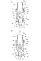
図4は上記メカクランプ機構1単独での詳細を示しており、同図(A)はメカクランプ機構1がアウタパネルPaとインナパネルPbを仮止めクランプした状態を、同図(B)は上記仮止め状態を解除するべくアンクランプした状態をそれぞれ示している。
FIG. 4 shows details of the
図4(A),(B)から明らかなように、中空円筒状のボデイ11の外周にはテーパ状のフランジ部12aと段状のショルダー部12bを有すスリーブ12をねじ部12cをもって装着してあるとともに、そのボデイ11の一端面には根元部側に着座面として機能する着座フランジ部13を有するテーパ状のロケートピン14を図示外の複数のボルトにて結合してある。
As is apparent from FIGS. 4A and 4B, a
ロケートピン14の一部には直径方向に貫通するすり割り溝16を形成してあるとともに、このすり割り溝16はボデイ11の内部空間と連通していて、これらのすり割り溝16およびボデイ11の内部空間には略鉤形状の一対のクランプアーム17を重ね合わせるようにして且つ左右対称に変位可能に挿入してある。また、ボデイ11の他端面からその内部にカラー18を挿入するとともに、そのカラー18に案内させるかたちでボデイ11と同心状の操作ピン19をスライド可能に挿入してある。操作ピン19はその一部がボデイ11から突出しているとともに、端部には二枚分のクランプアーム17の板厚を受容可能なスリット20を形成してあり、このスリット20にてクランプアーム17の他端を受容した上で後述する連結ピン21にて相互に連結してある。
A part of the locating
クランプアーム17はその鉤形状の先端部17aをロケートピン14の根元部の開口部から外部に臨ませてある一方、他端部を操作ピン19のスリット20に挿入した上で操作ピン19の直径方向に貫通する連結ピン21にて操作ピン19に連結し、さらに略くの字状に形成された溝カム22をボデイ11の直径方向に横架されたガイドピン23に係合させてある。
The
さらに、操作ピン19の外周には皿ばね、輪ばねあるいはばね座金等の円環状のばね部材24を積層配置した上で、操作ピン19の端部に装着したばね受け座25とスナップリング25aにてその抜け止めを施してある。このばね部材24は図4に示すように操作ピン19を介してクランプアーム17を常時ボデイ11内に引き込む方向、すなわちクランプアーム17がクランプ力を発生する方向に常時付勢しており、これによってばね部材24はクランプ力発生手段として機能することになる。
Further, an
より詳しくは、図4の(A)に示すように操作ピン19に外力を加えない状態ではクランプアーム17がばね部材24による付勢力をもってクランプ位置C1にあって、そのクランプ状態を自己保持している一方、同図(B)に示すように操作ピン19をボデイ11内に押し込むべくその操作ピン19をばね部材24の付勢力に抗して押圧操作することによりクランプアーム17がアンクランプ位置C2に移動するようになっており、特にクランプ状態では同図(A)に示すようにそのクランプアーム17の先端部17aと着座フランジ部13とをもって先に述べたアウタパネルPaとインナPbを挟圧状態としてクランプするようになっている。
More specifically, as shown in FIG. 4A, when no external force is applied to the
一方、上記ロケートピン14により位置決めされることになる相手側のパネル、すなわちアウタパネルPaとインナパネルPbには図4に示すようにそのロケートピン14に挿入されることになるロケート穴Rがそれぞれ形成されていて、ロケートピン14とロケート穴Rとの相互嵌合と同時にアウタパネルPaがロケートピン14側の着座フランジ部13に着座することでそのロケートピン14の軸心方向での位置決めが同時になされるようになっている。
On the other hand, as shown in FIG. 4, a locating hole R to be inserted into the locating
ここで、上記のメカクランプ機構1は、例えば特開平4−283034号公報あるいは特開2001−162469号公報等に記載の公知のロケート装置の構造を基本として、それ自体が可搬式で且つ取り扱いが容易な超小型のものとするべく改良を加えたものである。特に特開平4−283034号公報に記載のものは、圧縮コイルばねをクランプ力発生源としていわゆるセルフクランプ機能を有するものであるから、上記メカクランプ機構1は同公報に記載の構造を極小化したものと理解することができる。
Here, the
図5は先に図3に示したロボット5に持たせたアクチュエータ駆動のグリッパ52を拡大した概略斜視図であり、さらに図6,7はその詳細をそれぞれ示している。このグリッパ52は、対向配置したグリッパ本体部としての二つ一組のグリッパブロック26に対して、大径且つ長ストロークのグリッパシリンダ27と、小径且つ小ストロークのアンクランプシリンダ28とを直列に連結することにより構成してある。なお、ここではグリッパシリンダ27およびアンクランプシリンダ28としてエアシリンダが採用されていて、同時にアンクランプシリンダ28は後述するようにアンクランプ操作手段として機能することになる。
FIG. 5 is an enlarged schematic perspective view of the actuator-driven
二つ一組のグリッパブロック26は、所定の間隙を隔てて対向させることにより、先に述べたメカクランプ機構1と噛み合う受容穴29とともにグリッパアーム収容空間30を形成している。そして、図6,7のほか図8,9に示すように、そのグリッパアーム収容空間30には、対向配置されて且つ開閉可能な一対のプレート状のグリッパアーム31ととともに双方のグリッパアーム31が共有することになるバー状の中間レバー32を収容してあり、各グリッパアーム31は中間レバー32に対してヒンジピン33にて揺動可能に連結してある。なお、受容穴29の奥部には、図7に示すようにメカクランプ機構1側のスリーブ12のフランジ部12a(図4参照)に着座する着座面34を形成してある。
The pair of gripper blocks 26 are opposed to each other with a predetermined gap therebetween, thereby forming a gripper
また、各グリッパアーム31には略くの字状の溝カム35が形成してあり、この溝カム35を双方のグリッパブロック26,26間に掛け渡したガイドピン36に係合させてある。したがって、中間レバー32を後述するピストンロッド39とともにその軸心方向にスライド変位させることで、溝カム35とガイドピン36との相対変位のために一対のグリッパアーム31,31が開閉動作して、図10に示すようにその閉動作をもってメカクランプ機構1を把持する一方、図9に示すようにその開動作をもってメカクランプ機構1を解放することになる。
Each
図7のほか図9に示すように、グリッパシリンダ27は、シリンダチューブ37内に配置されたピストン38のほか、それと一体の中空状のピストンロッド39および二つの流出入ポート40,41を備えていて、ピストンロッド39の先端には先に述べた中間レバー32を連結してある。これにより、グリッパシリンダ27の伸縮作動に応じて一対のグリッパアーム31,31がメカクランプ機構1の把持動作もしくはその解放動作を行うことになる。
As shown in FIG. 9 in addition to FIG. 7, the
他方、アンクランプシリンダ28はグリッパシリンダ27と同心状に配置してあり、シリンダチューブ42内に配置されたピストン43のほか、それと一体のピストンロッド44および二つの流出入ポート45,46を備えていて、ピストンロッド44は先に述べたグリッパシリンダ27側の中空状のピストンロッド39にスライド可能に内挿されている。そして、図11に示すように一対のグリッパアーム31,31がメカクランプ機構1を把持した状態でアンクランプシリンダ28を伸長動作させることにより、そのメカクランプ機構1の操作ピン19を押圧操作することが可能となっている。
On the other hand, the unclamping
なお、図8において、47,48は各シリンダ27,28のエアの流出入ポートを切り換えるためのソレノイドバルブである。
In FIG. 8, 47 and 48 are solenoid valves for switching the air inflow / outflow ports of the
次に、上記のようなメカクランプ機構1およびグリッパ52の構造を前提として図2の溶接組立工程Sでの作業手順を図12〜15を参照しながら説明する。
Next, on the premise of the structure of the
図1,2のほか図12の(A)に示すように、作業者Mはパレット50からアウタパネルPaとインナパネルPbをセットとして取り出した上でパネル置き台51に置き、予め手元に用意してあるメカクランプ機構1を用いて図1および図12の(A)の形態で双方のパネルPa,Pb同士を仮止めして、いわゆる仮止めパネル部品Waを仮組みする。このパネル置き台51上での作業者Mによる仮止め作業がいわゆる仮組み工程での作業となる。
As shown in FIG. 12A in addition to FIGS. 1 and 2, the worker M takes out the outer panel Pa and the inner panel Pb from the
なお、後述するようにスポット溶接装置6にて溶接されたパネル部品Wから回収されたメカクランプ機構1がメカクランプ回収箱8に収容されていることから、作業者Mは予め複数ロット分のメカクランプ機構1をメカクランプ回収箱8から取り出して手元に用意しておくものとする。同時に、パネル置き台51の近くには先に述べたグリッパ52と同等の機能を有する可搬式の脱着工具を予め用意しておき、この脱着工具を使ってメカクランプ機構1によるパネルPa,Pb同士の仮止め、すなわち図4に示したようなメカクランプ機構1のアンクランプ動作とクランプ動作を行わせることが望ましい。
As will be described later, since the
一方、作業者Mの作業空間10に隣接する受け渡し位置10aには図12の(B)に示すようにグリッパ52を上向き姿勢としたハンド4が予め待機しており、作業者Mはパネル置き台51上にて仮組みした仮止めパネル部品Waをハンド4に移載して位置決めする。すなわち、この時にはハンド4側のグリッパ52は解放状態にあり、仮止めパネル部品Waに付帯しているそれぞれのメカクランプ機構1を対応するグリッパ52に受容させることでハンド4に対する仮止めパネル部品Waの一次的な位置決めがなされることになる。
On the other hand, the
ハンド4に対する仮止めパネル部品Waの位置決め完了後、作業者Mがパネル置き台51の近くに設けてある押釦スイッチ53(図2参照)を押圧操作すると、ロボット5が起動して自律動作を開始する。ロボット5が自律動作を開始した以降は、それと並行して作業者Mは次のサイクルに備えるべく、パレット50からアウタパネルPaとインナパネルPbをセットとして取り出し、パネル置き台51上にてメカクランプ機構1を用いて上記と同様に双方のパネルPa,Pb同士を仮止めして、いわゆる仮止めパネル部品Waを仮組みする。
After the positioning of the temporary fixing panel component Wa with respect to the
上記のようにロボット5が起動すると、最初にハンド4のグリッパ52が把持動作することより、ハンド4は図12の(C)に示すようにそれぞれのメカクランプ機構1を被把持部としてグリッパ52にて仮止めパネル部品Waを把持する。この把持動作がいわゆる把持工程での作業となる。さらに、ロボット5は予めティーチングしてある軌跡データ通りに移動を開始し、最初に図2のほか図13に示すように仮止めパネル部品Waを把持しているハンド4を上下反転させた上でその仮止めパネル部品Waをスポット溶接装置6側に搬送する。そして、ロボット5によりスポット溶接装置6とハンド4側に把持されたままの仮止めパネル部品Waとの相対位置決めが完了すると、スポット溶接装置6はメカクランプ機構1による仮止め位置近傍にスポット溶接を施し、上記のような相対位置決めとスポット溶接とを仮止めパネル部品Waに付帯しているメカクランプ機構1の数だけ繰り返すことになる。ここでのスポット溶接がいわゆる溶接工程での作業となる。
When the
仮止めパネル部品Waに付帯しているメカクランプ機構1の数だけ上記のスポット溶接が施されると、その時点でアウタ,インナのパネルPa,Pb同士が不離一体の関係となるが故に仮止めパネル部品Waは製品たるパネル部品Wと化し、同時になおもパネル部品Wに付帯しているメカクランプ機構1はその機能を失うことになる。
When the above spot welding is performed by the number of the
そこで、ロボット5は溶接済みのパネル部品Wを図2の台車7まで搬送した上、図13に示すようにハンド4にてメカクランプ機構1を把持したままの状態で、そのメカクランプ機構1を図4の(B)のようにアンクランプ動作させる。これにより、それまでのメカクランプ機構1による仮止め状態からパネル部品Wが解放されて、パネル部品Wはそのまま台車7に残されることになる。ここでの作業がいわゆる部品解放工程での作業となる。
Therefore, the
溶接後のパネル部品Wを台車7側に解放して移載したならば、ロボット5はハンド4を図2のメカクランプ回収箱8の真上に移動させ、図14の(A)に示すようにそれぞれのグリッパ52を解放動作させて、それまでのグリッパ52によるメカクランプ機構1の把持状態を解除する。ここでの作業が治具解放工程での作業となる。それに伴い、各メカクランプ機構1はメカクランプ回収箱8に自重落下して回収される。そして、メカクランプ回収箱8に回収されたメカクランプ機構1は繰り返し使用される。
When the welded panel part W is released to the
以上をもってロボット5のハンド4は図15のように全くの空荷状態となることから、そのハンド4を初期姿勢(図12の(B)の状態)に戻しながら図2の最初の受け渡し位置10aに移動させた上で停止する。以上をもってパネル部品Wの溶接のための1サイクルが終了する。
With the above, the
なお、図2において、細実線の矢印は作業者Mの動きを、太実線の矢印はロボット5の動きを、白抜き矢印は仮止めパネル部品Waまたは溶接後のパネル部品Wの動きをそれぞれに示す。
In FIG. 2, the thin solid arrow indicates the movement of the worker M, the thick solid arrow indicates the movement of the
以上のような一連のスポット溶接装置6によるスポット溶接動作、メカクランプ機構1の仮止め解除(アンクランプ動作)によるパネル部品Wの解放動作、およびハンド4側のグリッパ52によるメカクランプ機構1の解放動作の間に、先に述べたようにパネル置き台51側において作業者Mにより次の仮組みパネル部品Waの仮組みが行われて待機していることから、受け渡し位置10aに戻ってきたハンド4に対して作業者Mが次の仮止めパネル部品Waを位置決めすることで次のサイクルに移行し、以降は上記にサイクルを繰り返すことになる。なお、溶接対象となるパネル部品Wの仕様が異なる場合には、ロボット5は必要に応じてハンド置き台9との間でハンド4の持ち替えを行うことになる。
The spot welding operation by the series of
このように本実施の形態によれば、作業者Mとロボット5とが併存している溶接組立工程でありながら、作業者Mは仮止めパネル部品Waの仮組みとその供給を行う一方で、ロボット5は受け渡し位置10aからスポット溶接装置6への仮止めパネル部品Waの供給および取り出しだけでなく、それに続く台車7への溶接後のパネル部品Wの搬出・投入を行うようになっているので、例えば溶接後のパネル部品Wの搬出を、受け渡し位置10aにおいて溶接前の仮止めパネル部品Waの供給に先立って行う場合に比べて、サイクルタイムに占めるロボット稼働可能時間を長く確保することができ、ロボット5の能力を最大限に活用して効率的な生産を行えることになる。特に、パネル部品Wを構成することになるパネルのセット数が増えても、そのセット作業に要する時間はサイクルタイムに影響することはないから、一段と効率的な生産を行える。
As described above, according to the present embodiment, while the welding assembly process in which the worker M and the
また、図2の溶接組立工程Sは最小限の設備にて構成されているので、ロボット5やスポット溶接装置6等を予め移動可能に据え付けておけば、例えば生産台数の変動等により溶接組立工程全体を移設することも容易に行える。
Further, since the welding assembly process S in FIG. 2 is configured with minimum equipment, if the
1…仮止めクランプ治具としてのロケート・クランプ機構(メカクランプ機構)
2…アーム
4…ロボットハンド
5…ハンドリングロボット
6…溶接手段としてのスポット溶接装置
7…パネル部品搬出用台車
8…メカクランプ回収箱
10a…受け渡し位置
50…パレット
51…パネル置き台
52…グリッパ
M…作業者
Pa…パネル要素としてのアウタパネル
Pb…パネル要素としてのインナパネル
W…パネル部品
Wa…仮止めパネル部品
1 ... Locate clamp mechanism (mechanical clamp mechanism) as a temporary clamp
DESCRIPTION OF
Claims (5)
パネル要素同士の相対位置決めを行うべくそのパネル要素同士を仮止めクランプ治具にて仮止めして仮止めパネル部品とする仮組み工程と、
上記仮止めクランプ治具を被把持部としてハンドリングロボットにて仮止めパネル部品を把持する把持工程と、
上記ハンドリングロボットの自律動作をもって溶接手段と仮止めパネル部品との相対位置決めを行った上で溶接を施してパネル部品とする溶接工程と、
溶接後に上記ハンドリングロボットの自律動作をもって仮止めクランプ治具による仮止め状態からパネル部品を解放する部品解放工程と、
パネル部品の解放に続いて上記ハンドリングロボットの自律動作をもってロボット自体による把持状態から仮止めクランプ治具を解放する治具解放工程と、
を含み、
先行するパネル部品の溶接工程から治具解放工程までの作業進捗と並行して、次なるパネル部品となるべき仮止めパネル部品の仮組み工程作業が別のステージにて実行されるように設定されていることを特徴とする部品組立方法。 A method of assembling a panel component by welding and joining a plurality of panel elements,
Temporary assembly process to temporarily fix the panel elements to each other by temporarily fixing the panel elements with a temporary fixing clamp jig in order to perform relative positioning between the panel elements;
A gripping process of gripping a temporary fastening panel part with a handling robot using the temporary fastening clamp jig as a gripped portion;
A welding process in which welding is performed after performing relative positioning between the welding means and the temporary fixing panel component with the autonomous operation of the handling robot,
A part release process for releasing the panel parts from the temporarily fixed state by the temporary clamp jig with the autonomous operation of the handling robot after welding,
A jig releasing step for releasing the temporary clamping clamp jig from the gripping state by the robot itself with the autonomous operation of the handling robot following the release of the panel parts,
Including
In parallel with the work progress from the welding process of the preceding panel part to the jig releasing process, the temporary assembly process work of the temporary fixing panel part to be the next panel part is set to be executed in another stage. A method for assembling the parts.
パネル要素同士の仮止めを司る仮止めクランプ治具を被把持部としてパネル要素を把持するべく、その仮止めクランプ治具の把持とその解放とを行う脱着機能と、
把持した仮止めクランプ治具自体が仮止めしているパネル要素をその仮止めクランプ治具から少なくとも解放させるべく当該仮止めクランプ治具をアンクランプ動作させるパネル要素解放機能と、
を備えていることを特徴とするハンドリングロボット。 In the method in any one of Claims 1-3, It is the handling robot which conveys those panel elements in the state which temporarily fixed several panel elements,
Detachment function for holding and releasing the temporary clamping clamp jig in order to hold the panel element with the temporary clamping clamp jig for temporarily fixing the panel elements as a gripped portion;
A panel element release function for unclamping the temporary clamp clamp jig to release at least the panel element temporarily clamped by the gripped temporary clamp jig itself.
Handling robot, characterized in that it comprises a.
ハンドリングロボット自体は、仮止めクランプ治具を被把持部として把持したパネル要素の姿勢と位置を任意に変更可能であることを特徴とする請求項4に記載のハンドリングロボット。 The robot hand is capable of gripping and releasing a plurality of temporary fixing clamp jigs for temporarily fixing a plurality of panel elements,
The handling robot according to claim 4, wherein the handling robot itself can arbitrarily change the posture and position of the panel element gripped with the temporarily clamped jig as a gripped portion .
Priority Applications (1)
| Application Number | Priority Date | Filing Date | Title |
|---|---|---|---|
| JP2005255910A JP4876492B2 (en) | 2005-09-05 | 2005-09-05 | Parts assembly method and handling robot used in the method |
Applications Claiming Priority (1)
| Application Number | Priority Date | Filing Date | Title |
|---|---|---|---|
| JP2005255910A JP4876492B2 (en) | 2005-09-05 | 2005-09-05 | Parts assembly method and handling robot used in the method |
Publications (2)
| Publication Number | Publication Date |
|---|---|
| JP2007069220A JP2007069220A (en) | 2007-03-22 |
| JP4876492B2 true JP4876492B2 (en) | 2012-02-15 |
Family
ID=37931133
Family Applications (1)
| Application Number | Title | Priority Date | Filing Date |
|---|---|---|---|
| JP2005255910A Expired - Fee Related JP4876492B2 (en) | 2005-09-05 | 2005-09-05 | Parts assembly method and handling robot used in the method |
Country Status (1)
| Country | Link |
|---|---|
| JP (1) | JP4876492B2 (en) |
Families Citing this family (7)
| Publication number | Priority date | Publication date | Assignee | Title |
|---|---|---|---|---|
| JP4873171B2 (en) * | 2007-06-15 | 2012-02-08 | 株式会社安川電機 | Robot with robot hand |
| KR101790078B1 (en) * | 2016-05-11 | 2017-10-27 | (주) 세진하이테크 | Moving device of component |
| CN106737617B (en) * | 2016-11-29 | 2019-05-28 | 洛阳中重自动化工程有限责任公司 | Design method of mechanical arm for mounting lining plate of mill |
| CN108067887A (en) * | 2018-01-31 | 2018-05-25 | 湖北航嘉麦格纳座椅系统有限公司 | Slide assemblies assembly line and chair slide assembly line |
| CN108296764A (en) * | 2018-01-31 | 2018-07-20 | 湖北航嘉麦格纳座椅系统有限公司 | Slide assemblies pretreatment line |
| CN108381009A (en) * | 2018-05-09 | 2018-08-10 | 中车长春轨道客车股份有限公司 | Chassis corrugated plating electric arc spot welding pressing device |
| CN115716180A (en) * | 2022-12-13 | 2023-02-28 | 安徽江淮汽车集团股份有限公司 | Internal turning-over and pressing type positioning fixture |
Family Cites Families (8)
| Publication number | Priority date | Publication date | Assignee | Title |
|---|---|---|---|---|
| JP3078123B2 (en) * | 1992-07-31 | 2000-08-21 | 株式会社ヒロテック | Spot welding method and spot welding device |
| JPH07303996A (en) * | 1994-05-13 | 1995-11-21 | Toyota Motor Corp | Work positioning device |
| JP3872528B2 (en) * | 1995-08-24 | 2007-01-24 | 株式会社ヒロテック | Spot welding equipment |
| JPH10249536A (en) * | 1997-03-12 | 1998-09-22 | Nissan Motor Co Ltd | Method and equipment for welding vehicle body parts |
| JP3511485B2 (en) * | 1998-10-08 | 2004-03-29 | 豊田工機株式会社 | robot |
| JP3995865B2 (en) * | 2000-04-14 | 2007-10-24 | 日産自動車株式会社 | Work transfer device |
| JP3633489B2 (en) * | 2001-01-31 | 2005-03-30 | 日産自動車株式会社 | Locating device and body assembly device using locating device |
| JP4336572B2 (en) * | 2003-11-28 | 2009-09-30 | 本田技研工業株式会社 | Welding system |
-
2005
- 2005-09-05 JP JP2005255910A patent/JP4876492B2/en not_active Expired - Fee Related
Also Published As
| Publication number | Publication date |
|---|---|
| JP2007069220A (en) | 2007-03-22 |
Similar Documents
| Publication | Publication Date | Title |
|---|---|---|
| JP2006272492A (en) | Method and device for part assembling, and attaching/detaching tool for part assembling | |
| JP3633489B2 (en) | Locating device and body assembly device using locating device | |
| US8132801B2 (en) | Positioning and clamping apparatus | |
| KR101470451B1 (en) | Welding apparatus for pipes | |
| US10435094B2 (en) | Method of producing vehicle body assembly | |
| JP4876492B2 (en) | Parts assembly method and handling robot used in the method | |
| CN107791060B (en) | Workpiece pressing device | |
| WO2020170787A1 (en) | Supporting device for component gripping device and vehicular door removal device | |
| JP2018034226A (en) | Pallet clamping work-piece, pallet device, machine tool, and processing system | |
| JPH07303996A (en) | Work positioning device | |
| JPH0225711B2 (en) | ||
| JP2002001626A (en) | Automatic jig changing method in welding line | |
| JPH10249536A (en) | Method and equipment for welding vehicle body parts | |
| JPS6020802A (en) | Combined machine tool | |
| CN214489557U (en) | Pallet clamp of automatic assembly and detection production line of diaphragm energy accumulator | |
| JP2002355729A (en) | Automatic tool changer for machine tools | |
| JP3893652B2 (en) | Automatic assembling apparatus and its assembling method | |
| JPH0341292B2 (en) | ||
| JPH06190616A (en) | Jaw replacing device and robot hand at turning center | |
| JPS58212894A (en) | Presetting device for work in welding device | |
| JP2004299052A (en) | Locating device, and vehicle body assembling device using locating device | |
| JPS6363577A (en) | Welding method for automobile body | |
| JP2004345083A (en) | Locating device, and car assembling device using locating device | |
| JP4871094B2 (en) | Deformation workpiece chuck device | |
| JP2011037403A (en) | Front component assembling system and method for assembling front component |
Legal Events
| Date | Code | Title | Description |
|---|---|---|---|
| A621 | Written request for application examination |
Free format text: JAPANESE INTERMEDIATE CODE: A621 Effective date: 20080728 |
|
| A131 | Notification of reasons for refusal |
Free format text: JAPANESE INTERMEDIATE CODE: A131 Effective date: 20110412 |
|
| A521 | Written amendment |
Free format text: JAPANESE INTERMEDIATE CODE: A523 Effective date: 20110608 |
|
| TRDD | Decision of grant or rejection written | ||
| A01 | Written decision to grant a patent or to grant a registration (utility model) |
Free format text: JAPANESE INTERMEDIATE CODE: A01 Effective date: 20111101 |
|
| A01 | Written decision to grant a patent or to grant a registration (utility model) |
Free format text: JAPANESE INTERMEDIATE CODE: A01 |
|
| A61 | First payment of annual fees (during grant procedure) |
Free format text: JAPANESE INTERMEDIATE CODE: A61 Effective date: 20111114 |
|
| R150 | Certificate of patent or registration of utility model |
Free format text: JAPANESE INTERMEDIATE CODE: R150 |
|
| FPAY | Renewal fee payment (event date is renewal date of database) |
Free format text: PAYMENT UNTIL: 20141209 Year of fee payment: 3 |
|
| LAPS | Cancellation because of no payment of annual fees |