JP4655240B2 - Timing analysis support device - Google Patents
Timing analysis support device Download PDFInfo
- Publication number
- JP4655240B2 JP4655240B2 JP2008249190A JP2008249190A JP4655240B2 JP 4655240 B2 JP4655240 B2 JP 4655240B2 JP 2008249190 A JP2008249190 A JP 2008249190A JP 2008249190 A JP2008249190 A JP 2008249190A JP 4655240 B2 JP4655240 B2 JP 4655240B2
- Authority
- JP
- Japan
- Prior art keywords
- timing analysis
- file
- modified
- spef
- netlist
- Prior art date
- Legal status (The legal status is an assumption and is not a legal conclusion. Google has not performed a legal analysis and makes no representation as to the accuracy of the status listed.)
- Expired - Fee Related
Links
Images


Classifications
-
- G—PHYSICS
- G06—COMPUTING; CALCULATING OR COUNTING
- G06F—ELECTRIC DIGITAL DATA PROCESSING
- G06F30/00—Computer-aided design [CAD]
- G06F30/30—Circuit design
- G06F30/32—Circuit design at the digital level
- G06F30/33—Design verification, e.g. functional simulation or model checking
- G06F30/3308—Design verification, e.g. functional simulation or model checking using simulation
- G06F30/3312—Timing analysis
Landscapes
- Engineering & Computer Science (AREA)
- Computer Hardware Design (AREA)
- Physics & Mathematics (AREA)
- Theoretical Computer Science (AREA)
- Evolutionary Computation (AREA)
- Geometry (AREA)
- General Engineering & Computer Science (AREA)
- General Physics & Mathematics (AREA)
- Design And Manufacture Of Integrated Circuits (AREA)
Description
本発明は、クロック・メッシュ構造を含むクロックパスを有するLSIの遅延を検証するタイミング解析支援装置に関する。 The present invention relates to a timing analysis support apparatus for verifying a delay of an LSI having a clock path including a clock mesh structure.
LSIのクロック分配方式として、クロック・ツリー(clock tree)方式が知られている。クロック・ツリー方式は、木の枝(ツリー)状にクロック信号を分配する技術である。図1は、クロック・ツリー方式でクロックを分配するLSIの構成を示す回路図である。図1のLSIにおいて、クロック信号の到着時間の差(スキュー)が小さくなるように、回路を設計することが好ましい(例えば、特許文献1、2参照)。特許文献1には、論理単位の素子の配置広がりを考慮した配線負荷モデルを用い最適化した論理回路を生成する集積回路設計支援装置に関する技術が記載されている。また、特許文献2には、2つ以上の素子を一つの素子にまとめてネットリストを簡略化する技術が記載されている。
As an LSI clock distribution method, a clock tree method is known. The clock tree method is a technique for distributing clock signals in the form of tree branches. FIG. 1 is a circuit diagram showing a configuration of an LSI that distributes clocks by a clock tree method. In the LSI of FIG. 1, it is preferable to design a circuit so that a difference (skew) in arrival times of clock signals is small (see, for example,
クロック・ツリー方式のLSIでは、そのため、製造バラツキを考慮したSKEW計算が行われている。一般的に、クロック・ツリー方式のLSIは、配置広がり(距離)が大きければ遅延バラツキが大きくなり、段数が大きければ遅延バラツキが小さくなる。逆に、配置広がり(距離)が小さければ遅延バラツキが小さくなり、段数が小さければ遅延バラツキが大きくなる。このような相関があるため、スタティック・タイミング解析(STA)ツールでは、配置広がりと段数との2次元テーブル(ライブラリ)から、遅延バラツキ係数を決定し、下記の式を用いてSKEW計算をモデル化している。 In the clock tree type LSI, therefore, SKEW calculation is performed in consideration of manufacturing variations. In general, in a clock tree type LSI, the delay variation increases when the arrangement spread (distance) is large, and the delay variation decreases when the number of stages is large. Conversely, if the arrangement spread (distance) is small, the delay variation is small, and if the number of stages is small, the delay variation is large. Because of this correlation, the static timing analysis (STA) tool determines the delay variation coefficient from the two-dimensional table (library) of the arrangement spread and the number of stages, and models the SKEW calculation using the following formula: ing.
Setup skew:
送信クロック遅延−バラツキ係数(<1.0)×受信クロック遅延
Hold skew:
送信クロック遅延−バラツキ係数(>1.0)×受信クロック遅延
このとき、その製造バラツキを考慮したSKEW計算については、送信クロックと受信クロックの共通パスを認識して、その共通パス以降のクロックドライバの配置広がり(距離)を考慮する。クロック共通パスにおいては、バラツキを考慮する必要がない。そのため、共通パス分岐点(以下、CRPR(Clock Reconvergence Pessimism Removal)分岐点と記載する)から後の配置広がりや段数、クロック遅延について計算する。
Setup skew:
Transmission clock delay-variation coefficient (<1.0) x reception clock delay Hold skew:
Transmission clock delay-variation coefficient (> 1.0) x reception clock delay At this time, for the skew calculation considering the manufacturing variation, a common path between the transmission clock and the reception clock is recognized, and a clock driver after the common path Consider the arrangement spread (distance). There is no need to consider variations in the clock common path. For this reason, the arrangement spread, the number of stages, and the clock delay after the common path branch point (hereinafter referred to as a CRPR (Clock Revolution Psemism Removal) branch point) are calculated.
たとえば、第1フリップフロップFF1と第2フリップフロップFF2の間のパスのクロックを、上流に「一意に」トレースすると、第1CRPR分岐点までが共通パスと認識できる。また、第1フリップフロップFF1と第2フリップフロップFF2の間では、段数が1段で、配置広がりは第1範囲となる。第1フリップフロップFF1と第3フリップフロップFF3の間のパスのクロックを、上流に「一意に」トレースすると、第2CRPR分岐点までが共通パスと認識できる。そして、第1フリップフロップFF1と第3フリップフロップFF3の間では、段数が3段で、配置広がりが第2範囲となる。 For example, if the clock of the path between the first flip-flop FF1 and the second flip-flop FF2 is traced “uniquely” upstream, it can be recognized that the first CRPR branch point is a common path. Further, between the first flip-flop FF1 and the second flip-flop FF2, the number of stages is one and the arrangement spread is in the first range. When the clock of the path between the first flip-flop FF1 and the third flip-flop FF3 is traced "uniquely" upstream, it is possible to recognize up to the second CRPR branch point as a common path. Between the first flip-flop FF1 and the third flip-flop FF3, the number of stages is three and the arrangement spread is the second range.
クロック・ツリー方式は、レイアウト設計の自由度が高い。しかし、規模が大きい回路ではクロック信号の到着時間の差(スキュー)を小さくすることが困難な場合がある。回路規模が大きなLSIにおいて、スキューを小さくするクロック分配方式として、クロック・メッシュ(clock mesh)方式が知られている(例えば、特許文献3、4参照。)。クロック・メッシュ方式は、クロック遅延差を小さくし、チップ内製造バラツキによるクロック遅延変動を低減することが可能であり、規模が大きい回路に対してもスキュー(SKEW)を小さくすることが可能となる。そのため、ハイエンドLSIにおけるクロック構造において、メッシュ・アーキテクチャを用いたものが普及してきている。図2は、クロック・メッシュ方式のLSIの構成を示す回路図である。図2を参照すると、そのLSIでは、碁盤の目(メッシュ)状にクロック信号が分配されている。
上述の図1に示されているように、通常のクロック・ツリー分配では、データラインはバスを除いて通常シングル・ドライバであり、あるネットやセルのファンイン(ドライバ)側を辿ると必ず一意のセルに到達する。これに対して、クロックパスにメッシュ構造があると共通パスが認識できず正確な配置広がりを特定する事ができない問題が生じる。クロック・メッシュ構造ではファンイン側を辿るとドライバが一意に決まらず特殊なアルゴリズムやプログラム上の配慮が必要となる。このように、クロック・メッシュ構造は、マルチ・ドライバ構成となるので、一般的なCADツールでの扱いが難しい。 As shown in FIG. 1 above, in a normal clock tree distribution, the data line is usually a single driver except for the bus, and it is always unique when following the fan-in (driver) side of a net or cell. To reach the cell. On the other hand, if the clock path has a mesh structure, a common path cannot be recognized, and an exact arrangement spread cannot be specified. In the clock mesh structure, if the fan-in side is traced, the driver is not uniquely determined, and special algorithms and program considerations are required. Thus, since the clock mesh structure has a multi-driver configuration, it is difficult to handle with a general CAD tool.
スタティック・タイミング解析(STA)ツールにおいても例外ではない。図2に示されているようなLSIにおいて、メッシュ部に関しては、チップ内製造バラツキによる遅延変動の計算を行うツールが存在していない。したがって、バラツキを反映した計算モデルによる高精度なタイミング解析を行うことが困難な場合がある。たとえば、PLLからメッシュ段までをトランジスタレベルのネットリストに切り出して、配線メディア,トランジスタの製造バラツキ分をランダム要素にしたモンテカルロSPICEシミュレーション解析により計測した遅延を使う方法も考えられるが、実行時間の観点から現実的でない。 The static timing analysis (STA) tool is no exception. In the LSI as shown in FIG. 2, there is no tool for calculating delay variation due to in-chip manufacturing variation for the mesh portion. Therefore, it may be difficult to perform highly accurate timing analysis using a calculation model that reflects variations. For example, it is possible to use a delay measured by Monte Carlo SPICE simulation analysis with a random element of the wiring media and transistor manufacturing variation, from the PLL to the mesh stage, and using the delay measured by Monte Carlo SPICE simulation analysis. Not realistic.
配線の抵抗成分と容量成分とを含むSPEF(Standard Parasitic Exchange Format)ファイルを生成するRC抽出部と、そのSPEF(Standard Parasitic Exchange Format)ファイルに基づいて、SDF(Standard Delay Format)ファイルを生成する遅延計算部と、クロック・メッシュ構造のあるクロックパスについて、入力段からクロック・メッシュまでのネットリストを簡略化して修正回路モデルを生成するクロック・メッシュ計算部と、その修正回路モデルに基づいて、解析対象の半導体集積回路のタイミング解析を実行するタイミング解析部とを具備するタイミング解析支援装置を構成する。 An RC extraction unit that generates a SPEF (Standard Parasitic Exchange Format) file including a resistance component and a capacitance component of the wiring, and an SDF (Standard Delay Format) delay based on the SPEF (Standard Parasitic Exchange Format) file. Analyzing a clock path with a clock mesh structure based on a calculation section, a clock mesh calculation section that generates a modified circuit model by simplifying the netlist from the input stage to the clock mesh, and the modified circuit model A timing analysis support apparatus is provided that includes a timing analysis unit that performs timing analysis of a target semiconductor integrated circuit.
本願において開示される発明のうち、代表的なものによって得られる効果を簡単に説明すれば、クロック・メッシュ構造のあるクロックパスについて、PLLからメッシュまでのネットリストを簡略化し、PLLからメッシュのレシーバとなるドライバ(L1)までの製造バラツキによる遅延変動を、各ドライバL1の位置に依存する計算モデルとすることにより、既存のSTAシステムよりも高精度なタイミング解析を実行できる効果がある。な効果がある。 The effects obtained by typical ones of the inventions disclosed in the present application will be briefly described. For a clock path having a clock mesh structure, a net list from the PLL to the mesh is simplified, and a receiver from the PLL to the mesh is obtained. By making the delay variation due to manufacturing variations up to the driver (L1) to be a calculation model depending on the position of each driver L1, there is an effect that timing analysis can be performed with higher accuracy than the existing STA system. There is a great effect.
修正ネットリストを用いることで、CRPR分岐点を、ドライバL1或いは擬似外部端子としてタイミング解析を行う。また、配置広がりは修正SPEFを用いることで、ドライバL1とフリップフロップFFとの距離に応じた配置広がりを考慮してバラツキ遅延を計算できる。したがって、メッシュがチップ全面に配られていても、その大きな広がりは不問となる。 By using the corrected netlist, the timing analysis is performed using the CRPR branch point as the driver L1 or the pseudo external terminal. Further, by using the modified SPEF for the arrangement spread, the variation delay can be calculated in consideration of the arrangement spread according to the distance between the driver L1 and the flip-flop FF. Therefore, even if the mesh is distributed over the entire surface of the chip, its large spread is unquestioned.
以下、本発明の実施の形態を図面に基づいて説明する。なお、実施の形態を説明するための図において、同一の部材には原則として同一の符号を付し、その繰り返しの説明は省略する。 Hereinafter, embodiments of the present invention will be described with reference to the drawings. Note that components having the same function are denoted by the same reference symbols throughout the drawings for describing the embodiment, and the repetitive description thereof will be omitted.
図3は、本実施形態のタイミング解析装置10の構成を例示するブロックである。タイミング解析装置10は、情報処理装置1と、入力装置2と、出力装置3とを含んでいる。情報処理装置1は、プログラムに示される手順に従って、情報処理を高速に行う装置(コンピュータ)である。情報処理装置1は、入力、記憶、演算、制御および出力の5つの基本機能を備えている。入力装置2は、情報処理装置1にデータを入力するマンマシンインターフェースである。入力装置2の代表としては、例えば、キーボード、マウス、ペンタブレット、タッチパネルなどが例示される。出力装置3は、情報処理装置1の処理結果を外部に出力するマンマシンインターフェースである。出力装置3の代表として、ディスプレイやプリンタなどが例示される。
FIG. 3 is a block illustrating the configuration of the timing analysis apparatus 10 according to the present embodiment. The timing analysis device 10 includes an
情報処理装置1は、プログラム制御により動作するコンピュータであり、CPU4と、メモリ5と、大容量記憶装置6を備え、それらはバス7を介して接続されている。CPU4は、中央演算処理装置とも呼ばれ、情報処理装置1に備えられた各種装置の制御やデータの処理を行う。CPU4は、入力装置2などを介して供給されるデータを解釈して演算し、その演算結果を出力装置3などに出力する。
The
メモリ5は、DRAMやSRAMなどに代表される半導体記憶装置である。メモリ5は、CPU4の命令に応答してデータの書き込みを行う。また、メモリ5は、CPU4の命令に応答してデータの読み出しを行う。なお、本実施形態のメモリ5は、RAMに限定されることは無い。例えば、EEPROMやフラッシュメモリなどであってもよい。
The
大容量記憶装置6は、HDDなどに代表される情報を永続的に記憶する記憶装置である。大容量記憶装置6は、外部から供給される電源が遮断した場合であっても、情報を保持しつつける機能を備えている。なお、本実施形態の大容量記憶装置6は、HDDに限定されることは無い。例えば、EEPROMやフラッシュメモリなどであってもよい。
The
大容量記憶装置6は、タイミング解析支援プログラム8と、レイアウトデータ11と、SPEF(Standard Parasitic Exchange Format)12と、ネットリスト13と、SDF14と、クロックLatency/鈍り情報15と、修正ネットリスト16と、修正SPEF17と、修正SDF18と、タイミング制約19と、解析結果レポート20と、RC抽出ライブラリ21、セル遅延ライブラリ22を含んでいる。
The
タイミング解析支援プログラム8は、設計対象の半導体集積回路のタイミング解析を行う手順を示している。本実施形態においては、CPU4がタイミング解析支援プログラム8に示される手順で演算やデータ処理を実行する。それによって、情報処理装置1は、タイミング解析装置10として機能する。具体的には、情報処理装置1は、大容量記憶装置6から読み出されたタイミング解析支援プログラム8に示される手順に従って、後述するRC抽出ツール23、遅延計算ツール24、クロック・メッシュ修正ツール25およびタイミング解析ツール29として機能する。
The timing
レイアウトデータ11、ネットリスト13、タイミング制約19、RC抽出ライブラリ21、セル遅延ライブラリ22は、タイミング解析装置10への入力データである。
The
レイアウトデータ11は、配置・配線後のレイアウト情報を格納している。ネットリスト13は、レイアウトデータ11に対応し論理的な接続関係を表す情報を格納している。タイミング制約19は、検証回路のクロック周期の定義、ジッタを代表とする固定SKEW定義、マルチ・サイクルパス(複数サイクルの遅延が許されるパス)などのタイミング例外指定を格納している。
The
RC抽出ライブラリ21は、リーフ・セルの形状、セル内メタル図形情報、ターゲット半導体プロセスにおける配線層毎の容量・抵抗特性を格納している。セル遅延ライブラリ22は、入出力端子間遅延情報と、順序素子の場合はセットアップ時間、ホールド時間を格納している。
The
また、SPEF(Standard Parasitic Exchange Format)12、SDF14、クロックLatency/鈍り情報15、修正ネットリスト16、修正SPEF17、修正SDF18は、タイミング解析装置10の中間データである。
SPEF (Standard Parasitic Exchange Format) 12,
SPEF(Standard Parasitic Exchange Format)12は、寄生情報が抽出された配線の抵抗、容量(カップリング容量)を格納している。SDF14は、セル内のトランジスタ動作によるセル遅延と、配線遅延を格納している。クロックLatency/鈍り情報15は、PLLからメッシュのレシーバであるドライバ(レシーバ回路L1)入力までの最悪遅延値とレシーバ回路L1入力の波形鈍りを格納しており、フォーマットは一般的なSTAシステムがデザインに対してアノテートできる内容である。
A SPEF (Standard Parasitic Exchange Format) 12 stores the resistance and capacitance (coupling capacitance) of the wiring from which the parasitic information is extracted. The
修正ネットリスト16は、ネットリスト13を編集した内容を格納している。修正SPEF17は、SPEF(Standard Parasitic Exchange Format)12を編集した内容を格納している。修正SDF18は、SDF14を編集した内容を格納している。解析結果レポート20は、最終出力結果であり、タイミング解析によりセットアップ・ホールド遅延違反したパス情報を格納している。
The modified
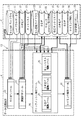
図4は、タイミング解析装置10を構成する機能ブロックとデータとの関連を例示するブロック図である。タイミング解析装置10は、RC抽出ツール23と、遅延計算ツール24、クロック・メッシュ修正ツール25と、タイミング解析ツール29とを含んでいる。また、クロック・メッシュ修正ツール25は、SDF編集ツール26と、SPEF編集ツール27と、ネットリスト編集ツール28とを含んでいる。
FIG. 4 is a block diagram illustrating the relationship between the functional blocks constituting the timing analysis apparatus 10 and data. The timing analysis apparatus 10 includes an
RC抽出ツール23は、RC抽出ライブラリ21とレイアウトデータ11を入力し、寄生情報を抽出してSPEF(Standard Parasitic Exchange Format)12に配線のRC情報を出力する。遅延計算ツール24は、セル遅延ライブラリ22とネットリスト13とSPEF(Standard Parasitic Exchange Format)12を入力し、配線メディアによる遅延時間、セル内遅延時間、同セットアップ・ホールド時間を計算して、SDF14に出力する。遅延計算ツール24は、このとき、後段に設けられたクロック・メッシュ修正ツール25で用いられる形式で、PLLからL1入力までの最悪遅延値とL1入力ピンの波形鈍りを、クロックLatency/鈍り情報15として出力する。
The
クロック・メッシュ修正ツール25は、ネットリスト13などのデータを読み込み、接続をトレースし、ECO(接続論理変更)を実行して、修正ネットリスト16、修正SPEF17、および修正SDF18を出力する機能を有するSTAツールで構成されている。なお、クロック・メッシュ修正ツール25は、SDF編集ツール26と、SPEF編集ツール27と、ネットリスト編集ツール28とを含んでいる。これらの機能ブロックの詳細な動作に関しては、後述する。
The clock
タイミング解析ツール29は、製造バラツキによる遅延変動を考慮したタイミング解析を実行して、その実行結果を、セットアップ・ホールド遅延違反やSKEWなどを示す解析結果レポート20として出力する。
The
以下に、図面を参照して、本実施形態の動作について説明を行う。以下では、本実施形態のタイミング解析装置10におけるクロック・メッシュ修正ツール25に関して、その動作を詳細に説明していく。図5は、ネットリスト編集ツール28の動作を例示するフローチャートである。ステップS101において、ネットリスト編集ツール28は、PLLインスタンスをサーチし、クロック出力ピンとそれに繋がるネットを記憶する。
The operation of the present embodiment will be described below with reference to the drawings. Below, the operation | movement regarding the clock
ステップS102において、そのPLL出力ピンからクロック・ツリーを、幅優先で探索しながら、クロック・メッシュを構成しているネット(クロック・メッシュネット)をサーチする。クロック・メッシュネットは、マルチ・ドライバとなっている。そのため、ある探索ネットのドライバ数が、2以上となっているかで判定できる。また、ステップS102において、クロック・メッシュネットに辿り着くまでの途中経路中のネットや、ドライバ・インスタンスを、後の動作に備えて全て記憶しておく。 In step S102, while searching the clock tree from the PLL output pin with width priority, a net (clock mesh net) constituting the clock mesh is searched. The clock mesh net is a multi-driver. Therefore, it can be determined whether the number of drivers of a certain search net is 2 or more. In step S102, all the nets and driver instances in the middle of the route until the clock mesh net is reached are stored for later operation.
ステップS103において、ステップS102の動作によって得られたクロック・メッシュネットに、レシーバとして繋がるドライバ(以下、レシーバ回路L1と記載する)の一覧を取得して記憶する。 In step S103, a list of drivers (hereinafter referred to as receiver circuit L1) connected as receivers is acquired and stored in the clock mesh net obtained by the operation in step S102.
ステップS104において、擬似外部端子とネットを構成し、ステップS103の動作で得られたレシーバ回路L1の一覧の入力ピンを、順次接続していく。ステップS105において、ステップS102の動作で記憶済みのネット、インスタンスを削除する。その後、ステップS106において、編集されたネットリストを修正ネットリスト16として出力する。
In step S104, a pseudo external terminal and a net are formed, and the input pins in the list of the receiver circuits L1 obtained by the operation in step S103 are sequentially connected. In step S105, the net and instance stored in step S102 are deleted. Thereafter, in step S106, the edited netlist is output as the corrected
図6は、SDF編集ツール26の動作を例示するフローチャートである。ステップS201において、SDF編集ツール26は、修正ネットリスト16に対して、読み出したクロックLatency/鈍り情報15を参照して、そのクロックLatency/鈍り情報15に含まれる情報を修正ネットリスト16付与する。この時、クロックLatency/鈍り情報15は、PLLから、複数のレシーバ回路L1を端点とした記述となっている。そのため、PLLを修正ネットリスト16の内の複数のレシーバ回路L1に繋がる擬似外部端子に読み替えながら入力する。そして、ステップS202において、SDF編集ツール26は、修正SDF18を出力する。
FIG. 6 is a flowchart illustrating the operation of the
図7は、SPEF編集ツール27の動作を例示するフローチャートである。ステップS301において、SPEF編集ツール27は、修正ネットリスト16に基づいて、擬似外部端子から複数のレシーバ回路L1へのネットのそれぞれに対して、ダミーの小さい容量・抵抗値を付与する。ここにおいて、後段のタイミング解析ツール29へは、遅延計算済みの修正SDF18が入力され、その値が使われる。そのため、SPEF(Standard Parasitic Exchange Format)12の内部の抵抗、容量の値が、遅延計算に使われることはない。
FIG. 7 is a flowchart illustrating the operation of the
ステップS302において、ここで一旦、SPEF(Standard Parasitic Exchange Format)12を仮SPEF30として出力する。ステップS303において、タイミング解析ツール29によって、製造バラツキに起因するSKEWの計算をする時に、レシーバ回路L1の後段の配置広がりのみを考慮させる目的で、仮SPEF30の擬似外部端子と複数のレシーバ回路L1のピンのペア記述の擬似端子座標を、レシーバ回路L1の入力端子座標と同じにする。
In step S <b> 302, the SPEF (Standard Parasitic Exchange Format) 12 is temporarily output as a
ステップS304において、編集内容を修正SPEF17として出力する。尚、ステップS303の処理やステップS304の処理を、STAツールなどで行うことなく、例えば、ストリームエディタなどで実行しても良い。その後、タイミング解析ツール29は、セル遅延ライブラリ22、修正ネットリスト16、修正SPEF17、修正SDF18、タイミング制約19を読み込み、製造バラツキによる遅延変動を考慮したタイミング解析を実行してセットアップ・ホールド遅延違反やSKEWなどを解析結果レポート20として出力する。
In step S304, the edited content is output as a modified
ここで、上述してきた本実施形態のタイミング解析装置10の動作について、具体的に説明を行う。図8は、以下の説明において、タイミング解析の対象となる解析対象回路31の構成を例示する回路図である。解析対象回路31は、PLL(Phase Lock Loop)32と、クロック・ツリー領域33と、クロック・メッシュ領域34と、複数のフリップフロップ(第1フリップフロップFF1〜第3フリップフロップFF3)を含んでいる。
Here, the operation of the timing analysis apparatus 10 of the present embodiment described above will be specifically described. FIG. 8 is a circuit diagram illustrating the configuration of the analysis target circuit 31 that is the target of timing analysis in the following description. The analysis target circuit 31 includes a PLL (Phase Lock Loop) 32, a
クロック・ツリー領域33は、第1インスタンスG11、第2インスタンスG12、第3インスタンスG21、第4インスタンスG22、第5インスタンスG23、第6インスタンスG24を含んでいる。クロック・メッシュ領域34は、クロック・メッシュネット35と、複数のレシーバ回路L1(第1レシーバ回路L1_1、第2レシーバ回路L1_2、第3レシーバ回路L1_3)を含んでいる。
The
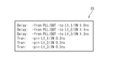
上述の解析対象回路31のような接続イメージのネットリスト、レイアウトデータがタイミング解析装置10に与えられ、RC抽出ツール23、遅延計算ツール24により順次処理されたとする。図9は、遅延計算ツール24により出力されたクロックLatency/鈍り情報15のフォーマットを例示するリストである。図9を参照すると、クロックLatency/鈍り情報15のDelay行は、−fromのピンから−toのピンまでのLatency遅延値を示す。Tran行は、−pinのピンでの波形鈍りを示す。なお、この記述は、本実施形態のおけるクロックLatency/鈍り情報15の構成を制限するものでは無い。
Assume that a netlist and layout data of a connection image such as the above-described analysis target circuit 31 are given to the timing analysis apparatus 10 and sequentially processed by the
上述の図5のフローチャートで例示したように、ネットリスト編集ツール28は、セル遅延ライブラリ22、ネットリスト13、SDF14、SPEF(Standard Parasitic Exchange Format)12を読み込み、ステップS101での処理を実行する。PLLをサーチすると、解析対象回路31に示される接続イメージより、PLL(Phase Lock Loop)32がサーチ結果として出力される。
As illustrated in the flowchart of FIG. 5 described above, the
ステップS102の処理では、クロック・ツリー領域33を、幅優先で探索しながら、クロック・メッシュ領域34をサーチするとクロック・メッシュネット35がサーチ結果として得られる。また、記憶された途中経路の情報は、ネットが第1ネットNG1、第2ネットNG21、第3ネットNG22、クロック・メッシュネット35であり、インスタンスが、第1インスタンスG11、第2インスタンスG12、第3インスタンスG21、第4インスタンスG22、第5インスタンスG23、第6インスタンスG24となる。
In the process of step S102, when the
次に、ネットリスト編集ツール28は、上述のステップS104の処理を実行する。ネットリスト編集ツール28は、クロック・メッシュネット35の後段に配置されたレシーバであるドライバ・リストとして、第1レシーバ回路L1_1、第2レシーバ回路L1_2、第3レシーバ回路L1_3を得る。その第1レシーバ回路L1_1、第2レシーバ回路L1_2および第3レシーバ回路L1_3に対して、それぞれ擬似外部端子第1擬似端子E1、第2擬似端子E2、第3擬似端子E3とネット(第1擬似ネットNE1、第2擬似ネットNE2、第3擬似ネットNE3)を新規に発生させてドライバ入力端子に順次接続する。
Next, the
次にネットリスト編集ツール28は、PLL(Phase Lock Loop)32と、記憶済みのネット(第1ネットNG1、第2ネットNG21、第3ネットNG22およびクロック・メッシュネット35と、インスタンス(第1インスタンスG11、第2インスタンスG12、第3インスタンスG21、第4インスタンスG22、第5インスタンスG23、第6インスタンスG24)を削除する。そして、編集されたネットリスト13を修正ネットリスト16として出力する。図10は、その修正ネットリスト16の接続イメージを例示する回路図である。
Next, the
その後、処理はSDF編集ツール26に移る。SDF編集ツール26は、上述のステップS201の処理を実行するためにクロックLatency/鈍り情報15を読み込む。このとき、SDF編集ツール26は、クロックLatency/鈍り情報15のTran行をそのまま読み込む。Delay行は、ツール内で−toのピンからファンイン側にトレースすると、一意に擬似外部端子が得られる。従って、SDF編集ツール26は、−from指定を、当該擬似外部端子に読み替えながら入力する。図11は、読み替えたファイル(クロックLatency/鈍り情報15a)を例示するリストである。その後、SDF編集ツール26は、修正SDF18を出力する。上述の図10には、修正SDF18のタイミング・アークイメージが例示されている。
Thereafter, the processing moves to the
その後、処理はSPEF編集ツール27に移る。SPEF編集ツール27は、修正ネットリスト16に対して、擬似外部端子から複数のレシーバ回路L1(第1レシーバ回路L1_1、第2レシーバ回路L1_2、第3レシーバ回路L1_3)のネットのそれぞれに対して、ダミーの小さい容量・抵抗値を付与する。ここで、SPEF編集ツール27は、一旦、SPEF(Standard Parasitic Exchange Format)12を、仮SPEF30として出力する。図12は、仮SPEF30のイメージを例示する回路図である。
Thereafter, the processing moves to the
SPEF編集ツール27は、仮SPEF30の擬似外部端子と、複数のレシーバ回路L1のピンペア記述の擬似端子座標を、レシーバ回路L1入力端子座標と同じにする。そして、その編集内容を、修正SPEF17として出力する。図13は、修正SPEF17のイメージを例示する回路図である。
The
タイミング解析ツール29は、セル遅延ライブラリ22、修正ネットリスト16、修正SPEF17、修正SDF18、タイミング制約19を読み込み、製造バラツキによる遅延変動を考慮したタイミング解析を実行してセットアップ・ホールド遅延違反やSKEWなどを解析結果レポート20として出力する。
The
上述のように、本実施形態のタイミング解析装置10は、クロック・メッシュ構造のあるクロックパスについて、PLLからメッシュまでのネットリストを簡略化し、PLLからメッシュのレシーバとなるドライバ(L1)までの製造バラツキによる遅延変動を、各L1の位置に依存する計算モデルとすることにより、既存のSTAシステムにより高精度なタイミング解析を実行することができる。 As described above, the timing analysis apparatus 10 of the present embodiment simplifies the netlist from the PLL to the mesh for a clock path having a clock mesh structure, and manufactures from the PLL to the driver (L1) that becomes the mesh receiver. By making the delay variation due to variation a calculation model that depends on the position of each L1, it is possible to perform highly accurate timing analysis by an existing STA system.
本実施形態のタイミング解析装置10は、修正ネットリスト16によりCRPR分岐点は、レシーバ回路L1、或いは、擬似外部端子となり、配置広がりは修正SPEF17により、レシーバ回路L1とフリップフロップの距離に応じた配置広がりとなり、それらを考慮してバラツキ遅延を計算できる。そのため、メッシュがチップ全面に配置されていても、その大きな広がりに依存することなくタイミング解析を行うことが可能となる。
In the timing analysis apparatus 10 of the present embodiment, the CRPR branch point becomes a receiver circuit L1 or a pseudo external terminal by the modified
以上、本願発明の実施の形態を具体的に説明した。本願発明は上述の実施の形態に限定されるものではなく、その要旨を逸脱しない範囲で種々変更可能である。 The embodiment of the present invention has been specifically described above. The present invention is not limited to the above-described embodiment, and various modifications can be made without departing from the scope of the invention.
1…情報処理装置
2…入力装置
3…出力装置
4…CPU
5…メモリ
6…大容量記憶装置
7…バス
8…タイミング解析支援プログラム
10…タイミング解析装置
11…レイアウトデータ
12…SPEF(Standard Parasitic Exchange Format)
13…ネットリスト
14…SDF
15…クロックLatency/鈍り情報
15a…クロックLatency/鈍り情報
16…修正ネットリスト
17…修正SPEF
18…修正SDF
19…タイミング制約
20…解析結果レポート
21…RC抽出ライブラリ
22…セル遅延ライブラリ
23…RC抽出ツール
24…遅延計算ツール
25…クロック・メッシュ修正ツール
26…SDF編集ツール
27…SPEF編集ツール
28…ネットリスト編集ツール
29…タイミング解析ツール
30…仮SPEF
31…解析対象回路
32…PLL(Phase Lock Loop)
33…クロック・ツリー領域
34…クロック・メッシュ領域
35…クロック・メッシュネット
G11…第1インスタンス
G12…第2インスタンス
G21…第3インスタンス
G22…第4インスタンス
G23…第5インスタンス
G24…第6インスタンス
NG1…第1ネット
NG21…第2ネット
NG22…第3ネット
L1…レシーバ回路
L1_1…第1レシーバ回路
L1_2…第2レシーバ回路
L1_3…第3レシーバ回路
FF1…第1フリップフロップ
FF2…第2フリップフロップ
FF3…第3フリップフロップ
E1…第1擬似端子
E2…第2擬似端子
E3…第3擬似端子
NE1…第1擬似ネット
NE2…第2擬似ネット
NE3…第3擬似ネット
101…クロック・ツリーLSI
102…クロック・メッシュLSI
DESCRIPTION OF
5 ...
13 ...
15 ... Clock Latency /
18 ... Modified SDF
19. Timing
31 ...
33 ...
102 ... Clock mesh LSI
Claims (14)
前記SPEF(Standard Parasitic Exchange Format)ファイルに基づいて、SDF(Standard Delay Format)ファイルを生成する遅延計算部と、
クロック・メッシュ構造のあるクロックパスについて、入力段からクロック・メッシュまでのネットリストを簡略化して修正回路モデルを生成するクロック・メッシュ計算部と、
前記修正回路モデルに基づいて、解析対象の半導体集積回路のタイミング解析を実行するタイミング解析部と
を具備し、
前記クロック・メッシュ計算部は、
ネットリスト編集ツールと、
SDFファイル編集ツールと、
SPEFファイル編集ツールと
を備え、
前記ネットリスト編集ツールは、
前記入力段を構成するインスタンスの出力ピンの後段に構成されたクロック・メッシュネットと、前記クロック・メッシュネットにレシーバとして繋がるドライバの入力ピンとを特定し、前記入力ピンに新たネットを介して擬似外部端子を接続して修正ネットリストを生成し、
前記SDFファイル編集ツールは、
前記インスタンスから前記ドライバまでの最悪遅延値と前記ドライバの入力の波形鈍りを示すクロックLatency/鈍り情報を読み出し、前記クロックLatency/鈍り情報に含まれる情報を前記修正ネットリストに付与して修正SDFファイルを生成し、
前記SPEFファイル編集ツールは、
前記修正ネットリストに基づいて、前記擬似外部端子から前記ドライバまでのネットに対して、ダミー容量とダミー抵抗を付与して修正SPEFファイルを生成し、
前記タイミング解析部は、
前記修正ネットリストと前記修正SDFファイルと前記修正SPEFファイルとに基づいて、前記半導体集積回路のタイミング解析を実行する
タイミング解析支援装置。 An RC extraction unit that generates a SPEF (Standard Parasitic Exchange Format) file including a resistance component and a capacitance component of the wiring;
A delay calculation unit that generates an SDF (Standard Delay Format) file based on the SPEF (Standard Parasitic Exchange Format) file;
For a clock path with a clock mesh structure, a clock mesh calculation unit that generates a modified circuit model by simplifying the netlist from the input stage to the clock mesh, and
A timing analysis unit that performs timing analysis of a semiconductor integrated circuit to be analyzed based on the modified circuit model ; and
The clock mesh calculation unit
A netlist editing tool,
SDF file editing tool,
SPEF file editing tool and
With
The netlist editing tool is:
Identify the clock mesh net configured after the output pin of the instance constituting the input stage and the driver input pin connected to the clock mesh net as a receiver, and connect the input pin to the pseudo external via the new net. Connect the terminals to generate a modified netlist,
The SDF file editing tool
A clock latency / blunt information indicating the worst delay value from the instance to the driver and the waveform dullness of the input of the driver is read, and the information included in the clock latency / blunt information is added to the modified netlist to be a modified SDF file Produces
The SPEF file editing tool is:
Based on the modified net list, a modified SPEF file is generated by adding dummy capacitance and dummy resistance to the net from the pseudo external terminal to the driver,
The timing analysis unit
A timing analysis support apparatus that performs timing analysis of the semiconductor integrated circuit based on the modified netlist, the modified SDF file, and the modified SPEF file .
前記タイミング解析部は、
セル遅延ライブラリとタイミング制約とを読み出し、前記修正ネットリストと前記修正SDFファイルと前記修正SPEFファイルと前記セル遅延ライブラリと前記タイミング制約とに基づいて、セットアップ・ホールド遅延違反したパス情報を含む解析結果レポートを生成する
タイミング解析支援装置。 The timing analysis support device according to claim 1 ,
The timing analysis unit
Analysis result including path information violating setup / hold delay based on reading of cell delay library and timing constraint, based on modified netlist, modified SDF file, modified SPEF file, cell delay library, and timing constraint Timing analysis support device that generates reports.
前記RC抽出部は、
RC抽出ライブラリと、前記半導体集積回路のレイアウトデータとに基づいて、前記半導体集積回路の寄生情報を抽出して、配線のRC情報を含む前記SPEFファイルを出力する
タイミング解析支援装置。 The timing analysis support device according to claim 1 or 2 ,
The RC extraction unit
A timing analysis support device that extracts parasitic information of the semiconductor integrated circuit based on an RC extraction library and layout data of the semiconductor integrated circuit, and outputs the SPEF file including RC information of the wiring.
前記遅延計算部は、
配線メディアによる遅延時間、セル内遅延時間、同セットアップ・ホールド時間を計算して、前記SDF(Standard Delay Format)ファイルを生成する
タイミング解析支援装置。 In the timing analysis support device according to any one of claims 1 to 3 ,
The delay calculation unit includes:
A timing analysis support device for generating a standard delay format (SDF) file by calculating a delay time by a wiring medium, a delay time in a cell, and the setup / hold time.
前記ネットリスト編集ツールは、
前記入力段から前記クロック・メッシュネットに辿り着くまでの途中経路中のネットとドライバ・インスタンスを全て記憶し、前記入力ピンに前記新たネットを介して前記擬似外部端子を接続した後、前記途中経路中のネットと前記ドライバ・インスタンスとを削除して前記修正ネットリストを生成する
タイミング解析支援装置。 In the timing analysis support device according to any one of claims 1 to 4 ,
The netlist editing tool is:
All the nets and driver instances in the intermediate path from the input stage to the clock mesh net are stored, and the pseudo external terminal is connected to the input pin via the new net, and then the intermediate path A timing analysis support device that generates the modified netlist by deleting a net in the driver and the driver instance.
前記SDFファイル編集ツールは、
読み出した前記クロックLatency/鈍り情報の記述に基づいて、前記入力段を、前記修正ネットリストの内部のドライバに繋がる擬似外部端子に読み替えながら、前記修正SDFファイルを生成する
タイミング解析支援装置。 In the timing analysis support device according to any one of claims 1 to 5 ,
The SDF file editing tool
A timing analysis support device that generates the modified SDF file while replacing the input stage with a pseudo external terminal connected to a driver in the modified netlist based on the read description of the clock latency / blunt information.
前記SPEFファイル編集ツールは、
前記修正ネットリストと前記SPEFファイルとに基づいて、仮SPEFファイルを生成し、
前記仮SPEFファイルの前記擬似外部端子と前記ドライバのピンとのペア記述の擬似端子座標を、前記ドライバの入力端子座標と同じにして前記修正SPEFファイルを生成する
タイミング解析支援装置。 In the timing analysis support device according to any one of claims 1 to 6 ,
The SPEF file editing tool is:
A temporary SPEF file is generated based on the modified netlist and the SPEF file;
A timing analysis support apparatus that generates the modified SPEF file by making the pseudo terminal coordinates of the pair description of the pseudo external terminal and the driver pin of the temporary SPEF file the same as the input terminal coordinates of the driver.
(a)配線の抵抗成分と容量成分とを含むSPEF(Standard Parasitic Exchange Format)ファイルを生成するステップと、
(b)前記SPEF(Standard Parasitic Exchange Format)ファイルに基づいて、SDF(Standard Delay Format)ファイルを生成するステップと、
(c)クロック・メッシュ構造のあるクロックパスについて、入力段からクロック・メッシュまでのネットリストを簡略化して修正回路モデルを生成するステップと、
(d)前記修正回路モデルに基づいて、解析対象の半導体集積回路のタイミング解析を実行するステップと
を具備する手順を示し、
前記(c)ステップは、
ネットリスト編集ステップと、
SDFファイル編集ステップと、
SPEFファイル編集ステップと
を含み、
前記ネットリスト編集ステップは、
前記入力段を構成するインスタンスの出力ピンの後段に構成されたクロック・メッシュネットと、前記クロック・メッシュネットにレシーバとして繋がるドライバの入力ピンとを特定するステップと、
前記入力ピンに新たネットを介して擬似外部端子を接続して修正ネットリストを生成するステップと
を含み、
前記SDFファイル編集ステップは、
前記インスタンスから前記ドライバまでの最悪遅延値と前記ドライバの入力の波形鈍りを示すクロックLatency/鈍り情報を読み出すステップと、
前記クロックLatency/鈍り情報に含まれる情報を前記修正ネットリストに付与して修正SDFファイルを生成するステップと
を含み、
前記SPEFファイル編集ステップは、
前記修正ネットリストに基づいて、前記擬似外部端子から前記ドライバまでのネットに対して、ダミー容量とダミー抵抗を付与して修正SPEFファイルを生成するステップを含み、
前記(d)ステップは、
前記修正ネットリストと前記修正SDFファイルと前記修正SPEFファイルとに基づいて、前記半導体集積回路のタイミング解析を実行するステップを含む
タイミング解析支援プログラム。 A timing analysis support program showing a procedure for causing a computer to function as a timing analysis support device for performing timing analysis of a semiconductor integrated circuit,
(A) generating a SPEF (Standard Parasitic Exchange Format) file including a resistance component and a capacitance component of the wiring;
(B) generating a SDF (Standard Delay Format) file based on the SPEF (Standard Parasitic Exchange Format) file;
(C) for a clock path having a clock mesh structure, generating a modified circuit model by simplifying a netlist from the input stage to the clock mesh;
And (d) based on said correction circuit model, shows a procedure and a step of performing timing analysis of a semiconductor integrated circuit to be analyzed,
The step (c) includes:
Netlist editing step,
SDF file editing step,
SPEF file editing step and
Including
The netlist editing step includes:
Identifying a clock mesh net configured at a subsequent stage of an output pin of an instance constituting the input stage, and an input pin of a driver connected as a receiver to the clock mesh net;
Connecting a pseudo external terminal to the input pin via a new net to generate a modified net list;
Including
The SDF file editing step includes:
Reading a clock latency / blunt information indicating the worst delay value from the instance to the driver and the blunting of the input waveform of the driver;
Generating a modified SDF file by adding information included in the clock latency / blunt information to the modified netlist;
Including
The SPEF file editing step includes:
Generating a modified SPEF file by adding a dummy capacitance and a dummy resistance to the net from the pseudo external terminal to the driver based on the modified netlist;
The step (d) includes:
A timing analysis support program including a step of performing timing analysis of the semiconductor integrated circuit based on the correction netlist, the correction SDF file, and the correction SPEF file .
前記(d)ステップは、
セル遅延ライブラリとタイミング制約とを読み出すステップと、
前記修正ネットリストと前記修正SDFファイルと前記修正SPEFファイルと前記セル遅延ライブラリと前記タイミング制約とに基づいて、セットアップ・ホールド遅延違反したパス情報を含む解析結果レポートを生成するステップと
を含む
タイミング解析支援プログラム。 In the timing analysis support program according to claim 8 ,
The step (d) includes:
Reading the cell delay library and timing constraints;
Generating an analysis result report including path information that violates a setup / hold delay based on the modified netlist, the modified SDF file, the modified SPEF file, the cell delay library, and the timing constraint. Support program.
前記(a)ステップは、
RC抽出ライブラリと、前記半導体集積回路のレイアウトデータとに基づいて、前記半導体集積回路の寄生情報を抽出して、配線のRC情報を含む前記SPEFファイルを出力するステップを含む
タイミング解析支援プログラム。 In the timing analysis support program according to claim 8 or 9 ,
The step (a) includes:
A timing analysis support program, comprising: extracting parasitic information of the semiconductor integrated circuit based on an RC extraction library and layout data of the semiconductor integrated circuit and outputting the SPEF file including RC information of the wiring.
前記(b)ステップは、
配線メディアによる遅延時間、セル内遅延時間、同セットアップ・ホールド時間を計算して、前記SDF(Standard Delay Format)ファイルを生成するステップを含む
タイミング解析支援プログラム。 The timing analysis support program according to any one of claims 8 to 10 ,
The step (b)
A timing analysis support program including a step of calculating a delay time by a wiring medium, a delay time in a cell, and a setup / hold time, and generating the SDF (Standard Delay Format) file.
前記ネットリスト編集ステップは、
前記入力段から前記クロック・メッシュネットに辿り着くまでの途中経路中のネットとドライバ・インスタンスを全て記憶するステップと、
前記入力ピンに前記新たネットを介して前記擬似外部端子を接続した後、前記途中経路中のネットと前記ドライバ・インスタンスとを削除して前記修正ネットリストを生成するステップと
を含む
タイミング解析支援プログラム。 The timing analysis support program according to any one of claims 8 to 11 ,
The netlist editing step includes:
Storing all of the nets and driver instances in the path from the input stage to the clock mesh net;
A timing analysis support program, comprising: connecting the pseudo external terminal to the input pin via the new net; and deleting the net in the intermediate path and the driver instance to generate the modified net list. .
前記SDFファイル編集ステップは、
読み出した前記クロックLatency/鈍り情報の記述に基づいて、前記入力段を、前記修正ネットリストの内部のドライバに繋がる擬似外部端子に読み替えながら、前記修正SDFファイルを生成するステップを含む
タイミング解析支援プログラム。 The timing analysis support program according to any one of claims 8 to 12 ,
The SDF file editing step includes:
A timing analysis support program including the step of generating the modified SDF file while replacing the input stage with a pseudo external terminal connected to a driver in the modified netlist based on the read description of the clock latency / blunt information .
前記SPEFファイル編集ツールは、
前記修正ネットリストと前記SPEFファイルとに基づいて、仮SPEFファイルを生成するステップと、
前記仮SPEFファイルの前記擬似外部端子と前記ドライバのピンとのペア記述の擬似端子座標を、前記ドライバの入力端子座標と同じにして前記修正SPEFファイルを生成するステップと
を含む
タイミング解析支援プログラム。 In the timing analysis support program according to any one of claims 8 to 13 ,
The SPEF file editing tool is:
Generating a temporary SPEF file based on the modified netlist and the SPEF file;
A timing analysis support program comprising: generating a modified SPEF file by setting a pseudo terminal coordinate of a pair description of the pseudo external terminal of the temporary SPEF file and a pin of the driver to be the same as an input terminal coordinate of the driver.
Priority Applications (2)
| Application Number | Priority Date | Filing Date | Title |
|---|---|---|---|
| JP2008249190A JP4655240B2 (en) | 2008-09-26 | 2008-09-26 | Timing analysis support device |
| US12/565,008 US8239795B2 (en) | 2008-09-26 | 2009-09-23 | Timing analyzing system for clock delay |
Applications Claiming Priority (1)
| Application Number | Priority Date | Filing Date | Title |
|---|---|---|---|
| JP2008249190A JP4655240B2 (en) | 2008-09-26 | 2008-09-26 | Timing analysis support device |
Publications (2)
| Publication Number | Publication Date |
|---|---|
| JP2010079737A JP2010079737A (en) | 2010-04-08 |
| JP4655240B2 true JP4655240B2 (en) | 2011-03-23 |
Family
ID=42059051
Family Applications (1)
| Application Number | Title | Priority Date | Filing Date |
|---|---|---|---|
| JP2008249190A Expired - Fee Related JP4655240B2 (en) | 2008-09-26 | 2008-09-26 | Timing analysis support device |
Country Status (2)
| Country | Link |
|---|---|
| US (1) | US8239795B2 (en) |
| JP (1) | JP4655240B2 (en) |
Families Citing this family (18)
| Publication number | Priority date | Publication date | Assignee | Title |
|---|---|---|---|---|
| EP2348409B1 (en) * | 2005-03-16 | 2017-10-04 | III Holdings 12, LLC | Automatic workload transfer to an on-demand center |
| JP5444985B2 (en) * | 2009-09-16 | 2014-03-19 | 日本電気株式会社 | Information processing device |
| JP5512227B2 (en) * | 2009-10-29 | 2014-06-04 | ルネサスエレクトロニクス株式会社 | Timing analysis apparatus, timing analysis method, and timing analysis program |
| US8316333B2 (en) * | 2010-07-22 | 2012-11-20 | International Business Machines Corporation | Implementing timing pessimism reduction for parallel clock trees |
| US8271923B2 (en) | 2010-07-22 | 2012-09-18 | International Business Machines Corporation | Implementing forward tracing to reduce pessimism in static timing of logic blocks laid out in parallel structures on an integrated circuit chip |
| JP5708014B2 (en) * | 2011-02-23 | 2015-04-30 | 日本電気株式会社 | Delay analysis apparatus, delay analysis method, and delay analysis program |
| US8635579B1 (en) * | 2012-12-31 | 2014-01-21 | Synopsys, Inc. | Local clock skew optimization |
| US9213358B2 (en) * | 2013-10-31 | 2015-12-15 | Qualcomm Incorporated | Monolithic three dimensional (3D) integrated circuit (IC) (3DIC) cross-tier clock skew management systems, methods and related components |
| KR20150069142A (en) * | 2013-12-13 | 2015-06-23 | 삼성전자주식회사 | Configurable clock mesh circuit, method thereof, and devices including the same |
| KR102328044B1 (en) * | 2014-10-21 | 2021-11-17 | 삼성전자주식회사 | Method for operating simulator and device performing the same |
| US11256846B2 (en) | 2015-03-27 | 2022-02-22 | Samsung Electronics Co., Ltd. | System and method of analyzing integrated circuit in consideration of a process variation and a shift |
| US10372869B2 (en) | 2015-03-27 | 2019-08-06 | Samsung Electronics Co., Ltd. | System and method of analyzing integrated circuit in consideration of a process variation |
| KR102718979B1 (en) * | 2017-02-10 | 2024-10-18 | 삼성전자주식회사 | Computer-implemented method and computing system for designing integrated circuit by considering Back-End-Of-Line |
| KR102402673B1 (en) * | 2017-04-28 | 2022-05-26 | 삼성전자주식회사 | Computer-implemented method and computing system for designing integrated circuit by considering process variations of Back-End-Of-Line |
| CN117272924A (en) * | 2017-04-28 | 2023-12-22 | 三星电子株式会社 | Method for designing integrated circuit |
| US10963610B1 (en) * | 2020-05-22 | 2021-03-30 | Cadence Design Systems, Inc. | Analyzing clock jitter using delay calculation engine |
| TWI785952B (en) * | 2021-12-30 | 2022-12-01 | 新唐科技股份有限公司 | Cipher accelerator and differential fault analysis method for encryption and decryption operations |
| TWI827237B (en) * | 2022-09-06 | 2023-12-21 | 新唐科技股份有限公司 | Cipher accelerator and method for tamper protection in cryptographic operations |
Citations (1)
| Publication number | Priority date | Publication date | Assignee | Title |
|---|---|---|---|---|
| JP2008152329A (en) * | 2006-12-14 | 2008-07-03 | Nec Electronics Corp | Circuit analysis method, circuit analysis program, and circuit simulation device |
Family Cites Families (10)
| Publication number | Priority date | Publication date | Assignee | Title |
|---|---|---|---|---|
| JPH03232267A (en) | 1990-02-07 | 1991-10-16 | Mitsubishi Electric Corp | Semiconductor integrated circuit device |
| JPH11232310A (en) | 1998-02-10 | 1999-08-27 | Matsushita Electric Ind Co Ltd | Integrated circuit design supporting device |
| US6876961B1 (en) * | 1999-08-27 | 2005-04-05 | Cisco Technology, Inc. | Electronic system modeling using actual and approximated system properties |
| JP3920124B2 (en) | 2002-03-26 | 2007-05-30 | Necエレクトロニクス株式会社 | Semiconductor integrated circuit clock wiring method and semiconductor integrated circuit |
| US6810505B2 (en) * | 2002-07-10 | 2004-10-26 | Lsi Logic Corporation | Integrated circuit design flow with capacitive margin |
| US7043708B2 (en) * | 2003-06-09 | 2006-05-09 | Lsi Logic Corporation | Intelligent crosstalk delay estimator for integrated circuit design flow |
| JP4921751B2 (en) | 2005-09-14 | 2012-04-25 | ルネサスエレクトロニクス株式会社 | Fault detection simulation system, fault detection simulation method and program |
| US8332793B2 (en) * | 2006-05-18 | 2012-12-11 | Otrsotech, Llc | Methods and systems for placement and routing |
| US20090013292A1 (en) * | 2007-07-03 | 2009-01-08 | Mentor Graphics Corporation | Context dependent timing analysis and prediction |
| US8365115B2 (en) * | 2009-03-06 | 2013-01-29 | Taiwan Semiconductor Manufacturing Company, Ltd. | System and method for performance modeling of integrated circuits |
-
2008
- 2008-09-26 JP JP2008249190A patent/JP4655240B2/en not_active Expired - Fee Related
-
2009
- 2009-09-23 US US12/565,008 patent/US8239795B2/en not_active Expired - Fee Related
Patent Citations (1)
| Publication number | Priority date | Publication date | Assignee | Title |
|---|---|---|---|---|
| JP2008152329A (en) * | 2006-12-14 | 2008-07-03 | Nec Electronics Corp | Circuit analysis method, circuit analysis program, and circuit simulation device |
Also Published As
| Publication number | Publication date |
|---|---|
| US8239795B2 (en) | 2012-08-07 |
| JP2010079737A (en) | 2010-04-08 |
| US20100083205A1 (en) | 2010-04-01 |
Similar Documents
| Publication | Publication Date | Title |
|---|---|---|
| JP4655240B2 (en) | Timing analysis support device | |
| US10902168B2 (en) | Computer-implemented method and computing system for designing integrated circuit by considering timing delay | |
| US20080184184A1 (en) | Method and system for conducting design explorations of an integrated circuit | |
| US9003349B1 (en) | Methods, systems, and articles of manufacture for implementing a physical electronic design with area-bounded tracks | |
| JP5495336B2 (en) | DELAY LIBRARY GENERATION DEVICE, DELAY LIBRARY GENERATION DEVICE CONTROL METHOD, COMPUTER PROGRAM, AND RECORDING MEDIUM | |
| KR102718979B1 (en) | Computer-implemented method and computing system for designing integrated circuit by considering Back-End-Of-Line | |
| US8954915B2 (en) | Structured placement of hierarchical soft blocks during physical synthesis of an integrated circuit | |
| JP4918934B2 (en) | Semiconductor integrated circuit delay analysis apparatus, delay analysis method, and program thereof | |
| US9047434B2 (en) | Clustering for processing of circuit design data | |
| Papa et al. | RUMBLE: an incremental, timing-driven, physical-synthesis optimization algorithm | |
| JP2010257164A (en) | Design method and program for semiconductor integrated circuit device | |
| US20050283750A1 (en) | Method and apparatus for designing a layout, and computer product | |
| US8375347B2 (en) | Driven metal critical dimension (CD) biasing | |
| JP5444985B2 (en) | Information processing device | |
| US8984456B2 (en) | Macro timing analysis device, macro boundary path timing analysis method and macro boundary path timing analysis program | |
| JP2012174226A (en) | Layout design method of semiconductor integrated circuit | |
| Lee et al. | Incremental timing-driven placement with approximated signoff wire delay and regression-based cell delay | |
| JP2009134439A (en) | Layout design method using soft macro, data structure for soft macro and creation method for soft macro library | |
| JP6089627B2 (en) | Power consumption estimation apparatus and power consumption estimation method | |
| JP5849973B2 (en) | Data processing apparatus, data processing system, data processing method, and data processing program | |
| US20240337687A1 (en) | Methods and systems for verifying integrated circuits | |
| Kulkarni et al. | Physical Design: Methodologies and Developments | |
| Shih et al. | Path-based cell flipping optimization for wirelength reduction and routability | |
| JP2006268165A (en) | Timing analyzing device for integrated circuit, timing optimizing device for integrated circuit, timing analyzing method for integrated circuit, timing optimizing method for integrated circuit, method for manufacturing integrated circuit board, control program and readable recording medium | |
| TW202341000A (en) | Cell libraries and computing systems |
Legal Events
| Date | Code | Title | Description |
|---|---|---|---|
| A977 | Report on retrieval |
Free format text: JAPANESE INTERMEDIATE CODE: A971007 Effective date: 20100811 |
|
| A131 | Notification of reasons for refusal |
Free format text: JAPANESE INTERMEDIATE CODE: A131 Effective date: 20100908 |
|
| A521 | Written amendment |
Free format text: JAPANESE INTERMEDIATE CODE: A523 Effective date: 20101108 |
|
| TRDD | Decision of grant or rejection written | ||
| A01 | Written decision to grant a patent or to grant a registration (utility model) |
Free format text: JAPANESE INTERMEDIATE CODE: A01 Effective date: 20101125 |
|
| A01 | Written decision to grant a patent or to grant a registration (utility model) |
Free format text: JAPANESE INTERMEDIATE CODE: A01 |
|
| A61 | First payment of annual fees (during grant procedure) |
Free format text: JAPANESE INTERMEDIATE CODE: A61 Effective date: 20101208 |
|
| FPAY | Renewal fee payment (event date is renewal date of database) |
Free format text: PAYMENT UNTIL: 20140107 Year of fee payment: 3 |
|
| R150 | Certificate of patent or registration of utility model |
Ref document number: 4655240 Country of ref document: JP Free format text: JAPANESE INTERMEDIATE CODE: R150 Free format text: JAPANESE INTERMEDIATE CODE: R150 |
|
| R250 | Receipt of annual fees |
Free format text: JAPANESE INTERMEDIATE CODE: R250 |
|
| LAPS | Cancellation because of no payment of annual fees |