JP4652351B2 - Substrate support apparatus and substrate support method - Google Patents
Substrate support apparatus and substrate support method Download PDFInfo
- Publication number
- JP4652351B2 JP4652351B2 JP2007023709A JP2007023709A JP4652351B2 JP 4652351 B2 JP4652351 B2 JP 4652351B2 JP 2007023709 A JP2007023709 A JP 2007023709A JP 2007023709 A JP2007023709 A JP 2007023709A JP 4652351 B2 JP4652351 B2 JP 4652351B2
- Authority
- JP
- Japan
- Prior art keywords
- substrate
- processing
- region
- air levitation
- air
- Prior art date
- Legal status (The legal status is an assumption and is not a legal conclusion. Google has not performed a legal analysis and makes no representation as to the accuracy of the status listed.)
- Expired - Fee Related
Links
Images


Landscapes
- Container, Conveyance, Adherence, Positioning, Of Wafer (AREA)
- Exposure Of Semiconductors, Excluding Electron Or Ion Beam Exposure (AREA)
- Exposure And Positioning Against Photoresist Photosensitive Materials (AREA)
- Coating Apparatus (AREA)
Description
本発明は、ガラス基板等の基板の加工処理を行う基板加工装置、当該基板を支持する基板支持装置、検査装置に関する。 The present invention relates to a substrate processing apparatus that processes a substrate such as a glass substrate, a substrate support apparatus that supports the substrate, and an inspection apparatus.
従来、基板加工装置は、ガラス基板等の薄板状の基板(ワーク)をステージ上に載置し、当該ステージを介して位置決めを行い、基板上に精密パターニング加工を行う。基板上にパターン形成を行う場合、相当の精度が要求され、加工対象の基板を定盤上の所定の位置に精度よく載置することが要求される。
近年、液晶カラーフィルター等のディスプレイの分野では、G6世代(1500mm×1800mm)、G7世代(1870mm×2200mm)等、ガラス基板のサイズが大型化すると共に、装置重量、装置コスト等が増大する傾向にある。
また、装置重量の軽量化、低コスト化を図るべく、エアスライダ方式の薄板搬送装置が提案されている(例えば、[特許文献1]参照。)。
Conventionally, a substrate processing apparatus places a thin plate-like substrate (work) such as a glass substrate on a stage, performs positioning through the stage, and performs precision patterning on the substrate. When pattern formation is performed on a substrate, considerable accuracy is required, and it is required to accurately place the substrate to be processed at a predetermined position on the surface plate.
In recent years, in the field of displays such as liquid crystal color filters, the G6 generation (1500 mm × 1800 mm), the G7 generation (1870 mm × 2200 mm), etc., tend to increase the size of the glass substrate and increase the device weight, device cost, etc. is there.
In order to reduce the weight of the apparatus and reduce the cost, an air slider type thin plate conveying apparatus has been proposed (see, for example, [Patent Document 1]).
また、鉛直方向の基板位置精度に関して、加工領域では高精度が要求されるが、加工領域以外の搬送領域では高精度が要求されない。そこで、エア浮上装置を用いて基板を支持する基板支持装置では、加工領域と搬送領域とで異なる浮上精度を有するエア浮上装置を設けることにより、コスト削減を図ることができる。この場合、高精度が要求される加工領域のエア浮上装置は、空気圧による押し出しと吸引とを併用して浮上精度を向上させるので、加工領域における基板の浮上量は、搬送領域における基板の浮上量より小さくなる。 Moreover, regarding the substrate position accuracy in the vertical direction, high accuracy is required in the processing region, but high accuracy is not required in the transfer region other than the processing region. Therefore, in a substrate support device that supports a substrate using an air levitation device, cost reduction can be achieved by providing an air levitation device having different levitation accuracy in the processing region and the transfer region. In this case, the air levitation device in the processing area where high accuracy is required improves the levitation accuracy by using both air pressure extrusion and suction, so the substrate flying height in the processing area is the same as the substrate flying height in the transfer area. Smaller.
しかしながら、加工領域と搬送領域とで基板の浮上量が異なると、搬送領域と加工領域との間を基板が移動する際に、基板の挙動が不安定になるという問題点がある。このため、基板の挙動を安定させるために必要な時間や移動距離が大きくなる。また、基板の撓みやばたつきが生じ、基板が割れて破損する可能性がある。さらに、基板の厚さは、例えば、従来0.7mmであったものが0.5mmになる等、薄くなる傾向にあり、基板が割れて破損する可能性も高くなっている。 However, if the floating amount of the substrate is different between the processing region and the transfer region, there is a problem that the behavior of the substrate becomes unstable when the substrate moves between the transfer region and the processing region. For this reason, the time and the movement distance necessary for stabilizing the behavior of the substrate are increased. Further, the substrate may be bent or fluttered, and the substrate may be broken and damaged. Furthermore, the thickness of the substrate tends to be thin, for example, 0.5 mm from the conventional 0.7 mm, and the possibility of the substrate being broken and broken is high.
本発明は、以上の問題点に鑑みてなされたものであり、加工精度を維持しつつ、安定した状態で基板の搬送及び加工を行うことを可能とする基板加工装置及び基板支持装置等を提供することを目的とする。 The present invention has been made in view of the above problems, and provides a substrate processing apparatus, a substrate support apparatus, and the like that can carry and process a substrate in a stable state while maintaining processing accuracy. The purpose is to do.
前述した目的を達成するために第1の発明は、基板が搬送される搬送領域と前記基板に対して加工装置による加工処理が行われる加工領域とを有する基板支持装置であって、前記搬送領域及び前記加工領域に渡って設けられ、前記基板を支持し所定方向に移動させる少なくとも1軸の移動支持装置と、前記搬送領域に設けられ、前記基板をエア浮上させて支持する搬送領域エア浮上装置と、前記加工領域に設けられ、前記基板をエア浮上させて支持する加工領域エア浮上装置と、を具備し、前記基板の前記搬送領域から前記加工領域への乗り換え時、前記搬送領域と前記加工領域での前記基板の浮上量の差による前記基板の鉛直方向の位置変化をなくすため、前記搬送領域エア浮上装置の上面の高さを、前記加工領域エア浮上装置の上面の高さより低く設置したことを特徴とする基板支持装置である。
In order to achieve the above-described object, the first invention is a substrate support apparatus having a transfer area in which a substrate is transferred and a processing area in which a processing process is performed on the substrate by a processing apparatus. And at least a single-axis movement support device that is provided over the processing region and supports the substrate and moves in a predetermined direction, and a transfer region air levitation device that is provided in the transfer region and supports the substrate by air levitation And a processing region air levitation device that is provided in the processing region and supports the substrate by levitating the substrate, and when the substrate is transferred from the transport region to the processing region, the transport region and the processing to eliminate the vertical position change of the substrate due to the difference in flying height of the substrate in a region, the height of the upper surface of the transfer area air floating devices, high of the upper surface of the working area air floating device A substrate supporting device, characterized in that installed lower.
第1の発明の基板支持装置は、要求精度が低い搬送領域エア浮上装置と要求精度が高い加工領域エア浮上装置とを備える。搬送領域エア浮上装置の基板支持面(上面)の高さは、加工領域エア浮上装置の基板支持面(上面)の高さより低い。望ましくは、加工領域エア浮上装置の基板支持面の高さと搬送領域エア浮上装置の基板支持面の高さとの差は、搬送領域エア浮上装置による基板の浮上量と加工領域エア浮上装置による基板の浮上量との差に略等しくする。また、基板を支持し基板のアライメントを行うアライメント支持装置を設けてもよい。 A substrate support apparatus according to a first aspect of the present invention includes a transfer area air levitation device with low required accuracy and a processing area air levitation device with high required accuracy. The height of the substrate support surface (upper surface) of the transfer region air levitation device is lower than the height of the substrate support surface (upper surface) of the processing region air levitation device. Desirably, the difference between the height of the substrate support surface of the processing area air levitation apparatus and the height of the substrate support surface of the transfer area air levitation apparatus is determined by the amount of floating of the substrate by the transfer area air levitation apparatus and the height of the substrate by the processing area air levitation apparatus. It should be approximately equal to the difference from the flying height. Moreover, you may provide the alignment support apparatus which supports a board | substrate and performs alignment of a board | substrate.
第1の発明の基板支持装置では、搬送領域から加工領域への乗換時に、基板の鉛直方向位置は変化しない。これにより、基板の撓みやばたつきが抑制されるので、基板の破損を防止することができる。
また、加工領域における基板の挙動及び姿勢が安定するので、加工領域の全範囲を加工可能領域とすることができる。これにより、基板支持装置の装置長を短くすることができる。
In the substrate support apparatus according to the first aspect of the present invention, the vertical position of the substrate does not change when transferring from the transfer region to the processing region. Thereby, since bending and fluttering of a board | substrate are suppressed, damage to a board | substrate can be prevented.
Further, since the behavior and posture of the substrate in the processing region are stabilized, the entire range of the processing region can be set as a processable region. Thereby, the apparatus length of a board | substrate support apparatus can be shortened.
第2の発明は、搬送領域において搬送され加工領域において加工装置による加工処理が行われる基板を支持する基板支持方法であって、前記搬送領域及び前記加工領域に渡って前記基板を支持し所定方向に移動させる移動支持ステップと、前記搬送領域において搬送領域エア浮上装置により前記基板をエア浮上させて支持する搬送領域エア浮上ステップと、前記加工領域において加工領域エア浮上装置により前記基板をエア浮上させて支持する加工領域エア浮上ステップと、を具備し、前記基板の前記搬送領域から前記加工領域への乗り換え時、前記基板の鉛直方向の位置変化をなくすため、前記搬送領域エア浮上ステップによる前記基板の浮上量と前記加工領域エア浮上ステップによる前記基板の浮上量との差が、前記加工領域における前記加工領域エア浮上装置の上面の高さと前記搬送領域における前記搬送領域エア浮上装置の上面の高さとの差に略等しくなるよう、前記搬送領域エア浮上装置の上面の高さを、前記加工領域エア浮上装置の上面の高さより低く設置したことを特徴とする基板支持方法である。 A second invention is a substrate support method for supporting a substrate that is transported in a transport region and processed in a processing region by a processing device, and that supports the substrate over the transport region and the processing region, and in a predetermined direction. A moving support step for moving the substrate in the transfer region, a transfer region air levitation step for supporting the substrate by air levitation in the transfer region, and a processing region air levitation device in the processing region for air levitation. And a processing region air levitation step for supporting the substrate, and the substrate by the transport region air levitation step to eliminate a vertical position change of the substrate when the substrate is transferred from the transport region to the processing region. the difference between the flying height of the substrate flying height and by the working area air floating step of, prior to the said machining area So that substantially equal to the difference between the height of the upper surface of the transfer area air floating device in the processing region height and the conveyance area of the upper surface of the air floating device, the height of the upper surface of the transfer area air floating device, the working area air It is a substrate support method characterized by being installed lower than the height of the upper surface of the levitation device .
第2の発明は、搬送領域において搬送され加工領域において加工装置による加工処理が行われる基板を支持する基板支持方法に関する発明である。 2nd invention is invention regarding the board | substrate support method which supports the board | substrate conveyed in a conveyance area | region and processed by a processing apparatus in a process area | region.
本発明によれば、加工精度を維持しつつ、安定した状態で基板の搬送及び加工を行うことを可能とする基板加工装置及び基板支持装置等を提供することができる。 According to the present invention, it is possible to provide a substrate processing apparatus, a substrate support apparatus, and the like that can carry and process a substrate in a stable state while maintaining processing accuracy.
以下、添付図面を参照しながら、本発明に係る基板加工装置等の好適な実施形態について詳細に説明する。なお、以下の説明及び添付図面において、略同一の機能構成を有する構成要素については、同一の符号を付することにより重複説明を省略することにする。 Hereinafter, preferred embodiments of a substrate processing apparatus and the like according to the present invention will be described in detail with reference to the accompanying drawings. In the following description and the accompanying drawings, the same reference numerals are given to components having substantially the same functional configuration, and redundant description will be omitted.
(1.基板加工装置1の構成)
最初に、図1〜図3を参照しながら、本発明の実施形態に係る基板加工装置1の構成について説明する。
図1は、基板加工装置1の概略斜視図である。
図2は、基板加工装置1のYZ平面断面図である。
尚、X方向は基板3の搬送方向を示し、Y方向は加工装置17の移動方向を示し、Z方向は鉛直方向回転軸を示し、θ方向はその回転方向を示す。X軸、Y軸、Z軸は、互いに直角をなす。
(1. Configuration of the substrate processing apparatus 1)
First, the configuration of the
FIG. 1 is a schematic perspective view of the
FIG. 2 is a YZ plane sectional view of the
The X direction indicates the transport direction of the
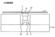
基板加工装置1は、X方向移動支持装置5、アライメント支持装置7、搬送領域エア浮上装置11、加工領域エア浮上装置13、搬送領域エア浮上装置15、加工装置17、Y方向移動装置19、アライメントカメラ21、ガントリ23、ベース24等から構成される。
The
基板加工装置1は、基板3に対して加工装置17により加工処理を施し、カラーフィルタ、電子回路等の微細ピッチのパターン等を形成する装置である。
。
基板3は、加工処理の対象物であり、例えば、ガラス基板、シリコンウェハ、プリント基板等の基板である。
The
.
The
X方向移動支持装置5は、基板3を支持し、X方向に移動させると共に、X方向の位置決めを行う装置である。X方向移動支持装置5は、ガイド機構27、移動用アクチュエータ29を備える。
ガイド機構27は、例えば、スライダ及びスライドレール、エアースライドである。移動用アクチュエータ29は、例えば、ステップモータ、サーボモータ、リニアモータである。
尚、搬送領域エア浮上装置11及び加工領域エア浮上装置13及び搬送領域エア浮上装置15のX方向中央部には、X方向移動支持装置5が設置される。
The X-direction
The
In addition, an X-direction
アライメント支持装置7は、X方向移動支持装置5の上部に設けられる。アライメント支持装置7は、エアパッド31、回転用アクチュエータ33を備える。アライメント支持装置7は、基板3をθ方向に回転させてアライメント処理を行うと共に、基板3を支持しつつX方向に移動可能である。
The
エアパッド31は、アライメント支持装置7の上面に設けられる。エアパッド31は、基板3を下方から支持する支持面である。エアパッド31は、基板3を吸着して固定支持したり、基板3に空気を吹き出して浮上させ非接触支持する。
基板3の吸着は、エアパッド31と基板3との間の空気を減圧あるいは真空にすることにより行われる(バキューム、吸気)。基板3の非接触支持は、エアパッド31と基板3との間に空気を送り込むことにより行われる(ブロー、圧気)。エアパッド31には、空気を吸引あるい吹き出すための小孔(図示しない)が設けられる。
回転用アクチュエータ33は、例えば、ダイレクトドライブモータである。
The
Adsorption of the
The
搬送領域エア浮上装置11、加工領域エア浮上装置13、搬送領域エア浮上装置15は、それぞれ、搬送領域51、加工領域53、搬送領域55に設けられる。搬送領域エア浮上装置11、加工領域エア浮上装置13、搬送領域エア浮上装置15は、エアフロートであり、基板3を空気圧で押し上げあるいは吸引することにより、非接触に支持する機能を持った板(多孔質板等)である。搬送領域エア浮上装置11、加工領域エア浮上装置13、搬送領域エア浮上装置15は、所定のZ方向精度(基板3と加工装置17との間の相対距離精度)を実現する装置である。加工領域エア浮上装置13のZ方向精度は、搬送領域エア浮上装置11及び搬送領域エア浮上装置15のZ方向精度と比較して、高精度である。
The conveyance area
図3は、基板3の浮上量を示すグラフである。
Z方向精度が異なると基板3の浮上量も異なる。高精度が要求される加工領域エア浮上装置13における基板3の浮上量は「h2」であり、高精度が要求されない搬送領域エア浮上装置11及び搬送領域エア浮上装置15における基板3の浮上量は「h1」である。但し、「h2<h1」である。
FIG. 3 is a graph showing the flying height of the
If the Z direction accuracy is different, the flying height of the
加工領域エア浮上装置13と、搬送領域エア浮上装置11及び搬送領域エア浮上装置15との間には、基板3の浮上量に応じた段差が設けられる。搬送領域エア浮上装置11及び搬送領域エア浮上装置15の上面の高さが、加工領域エア浮上装置13の上面の高さと比較して、基板3の浮上量差「h1−h2」だけ低くなるように、各装置が組み付けられる。
A step corresponding to the floating amount of the
加工装置17は、基板3に対して加工処理を施す装置であり、例えば、インクジェットヘッドユニット、ダイコートユニット、レーザ照射ヘッドユニット等である。加工装置17は、Y方向移動装置19を介してガントリ23に設けられる。Y方向移動装置19は、加工装置17をY方向に移動させて位置決めを行う。
The
アライメントカメラ21は、アライメント支持装置7に吸着固定された基板3のθ方向角度及びXY座標を検出するために、基板3の所定箇所(基板上に形成されるアライメントマークやパターン等)を撮像するカメラである。アライメントカメラ21は、基板加工装置1のフレーム20に固定支持される。アライメントカメラ21を複数設けてもよいし、異なる視野(例えば、高精度用、粗精度用)のアライメントカメラ21を設けるようにしてもよい。
The
尚、アライメント支持装置7は、搬送領域51にアライメントカメラ21を設けることにより、搬送領域51においてアライメント処理を行うことができる。
また、アライメント支持装置7は、基板3を支持しつつX方向に移動可能であるので、アライメントカメラ21を加工領域53に設けることにより、加工領域53において基板3のアライメント処理を行ってもよい。このように、加工部近傍でアライメント処理を行うことにより、加工に対するアライメント精度の向上を図ることができる。
The
Further, since the
(2.プロセス制御)
次に、図4を参照しながら、基板加工装置1のプロセス制御について説明する。
図4は、基板加工装置1のプロセス制御の流れを示す図である。
アライメントカメラ21の撮像画像は、画像処理装置37に入力される。画像処理装置37は、撮像画像に基づいて基板3のθ方向角度及びXY座標を抽出する処理を行う。ステージコントローラ39は、抽出したデータを所定のデータと比較してそれらの偏差を算出し、偏差を小さくするように制御量を演算する。
(2. Process control)
Next, process control of the
FIG. 4 is a diagram showing a flow of process control of the
A captured image of the
サーボアンプθ41は、ステージコントローラ39から送られるθ方向制御量に基づいてアライメント支持装置7に制御信号を送出する。アライメント支持装置7は、基板3のθ方向のアライメントを行う。
サーボアンプX43は、ステージコントローラ39から送られるX方向制御量に基づいてX方向移動支持装置5に制御信号を送出する。X方向移動支持装置5は、基板3をX方向に移動させる。
サーボアンプY45は、ステージコントローラ39から送られるY方向制御量に基づいてY方向移動装置19に制御信号を送出する。Y方向移動装置19は、加工装置17をY方向に移動させる。
プロセスシステム47は、ステージコントローラ39から送られる制御量に基づいて、加工装置17の加工タイミングを調整する。
The servo amplifier θ41 sends a control signal to the
The servo amplifier X43 sends a control signal to the X-direction
The servo amplifier Y45 sends a control signal to the Y-
The
(3.基板加工装置1の動作)
次に、図5を参照しながら、基板加工装置1の動作について説明する。
(3. Operation of substrate processing apparatus 1)
Next, the operation of the
図5は、基板加工装置1の動作を示すフローチャートである。
基板加工装置1は、搬送処理(ステップ101)、補正量算出処理(ステップ102)、アライメント処理(ステップ103)、加工処理(ステップ104)の各処理を順次行う。
FIG. 5 is a flowchart showing the operation of the
The
(3−1.搬送処理:ステップ101)
搬送領域エア浮上装置11は、基板3をエア浮上させて非接触支持する。基板加工装置1は、アライメント支持装置7のエアパッド31により基板3を吸着固定する。基板加工装置1は、X方向移動支持装置5によりアライメント支持装置7及び基板3をX方向に移動させて加工領域エア浮上装置13まで搬送する。
(3-1. Conveyance process: Step 101)
The transport area
(3−2.補正量算出処理:ステップ102)
加工領域エア浮上装置13は、基板3をエア浮上させて非接触支持する。基板加工装置1は、アライメントカメラ21により基板3に付されたアライメントマークを撮像し、当該アライメントマークのXY座標に基づいてθ方向の補正量及びX方向ずれ量及びY方向ずれ量を算出する。
(3-2. Correction amount calculation process: Step 102)
The processing region
(3−3.アライメント処理:ステップ103)
加工領域エア浮上装置13は、基板3をエア浮上させて非接触支持する。基板加工装置1は、ステップ102の処理により算出したθ方向補正量に基づいて、回転用アクチュエータ33により基板3をθ方向に回転させてアライメント処理を行う。
(3-3. Alignment process: Step 103)
The processing region
(3−4.加工処理:ステップ104)
加工領域エア浮上装置13は、基板3をエア浮上させて非接触支持し、基板3全体のZ方向精度を維持する。基板加工装置1は、アライメント支持装置7のエアパッド31により基板3を吸着固定してもよいし、空気圧による押し出しと吸引により非接触支持してもよい。
基板加工装置1は、Y方向ずれ量に基づいて加工装置17のY方向位置決めを行い、X方向ずれ量に基づいて加工処理の開始タイミング及び停止タイミングを調整し、加工装置17により基板3に対して加工処理を行う。
(3-4. Processing: Step 104)
The processing region
The
尚、基板3と加工装置17との間の相対距離精度(Z方向精度)を向上させるべく、加工装置17側に基板3の位置を測定するセンサを設け、リアルタイムにフィードバックして、加工領域エア浮上装置13の空気圧を制御するようにしてもよい。
In addition, in order to improve the relative distance accuracy (Z direction accuracy) between the
以上の過程を経て、基板加工装置は、X方向移動支持装置5により基板3をX方向に搬送し、アライメント支持装置7により基板3のθ方向の位置決め行い、加工領域エア浮上装置13によりZ方向精度を維持して基板3の加工を行う。
Through the above process, the substrate processing apparatus conveys the
(4.基板3の挙動及び姿勢)
次に、図6〜図11を参照しながら、基板3の挙動及び姿勢について説明する。
(4. Behavior and posture of substrate 3)
Next, the behavior and posture of the
(4−1.本発明の実施形態に係る基板加工装置1の場合)
図6〜図8は、本発明の実施の形態に係る基板加工装置1における、基板3の挙動及び姿勢を示す図である。
図6は、基板加工装置1のXZ平面断面図である。図7は、図6のA−A線断面図である。図8は、図6のB−B線断面図である。尚、理解の容易のためフレーム20やガントリ23等の一部図示を省略する。
(4-1. In the case of the
6-8 is a figure which shows the behavior and attitude | position of the board |
FIG. 6 is an XZ plane sectional view of the
搬送領域エア浮上装置11及び搬送領域エア浮上装置15の上面からの基板3の浮上量は「h1」である。加工領域エア浮上装置13の上面からの基板3の浮上量は「h2」である。
搬送領域エア浮上装置11及び搬送領域エア浮上装置15の上面の高さは、加工領域エア浮上装置13の上面の高さより「h1−h2」低い。従って、搬送領域51〜加工領域53〜搬送領域55に渡って基板3が移動する際、基板3のZ方向位置は、常時一定に維持される。
The flying height of the
The heights of the upper surfaces of the transfer area
図6に示すように、X方向では搬送領域51〜加工領域53〜搬送領域55に渡って、基板3のZ方向位置は一定である。図7及び図8に示すように、搬送領域51及び加工領域53のいずれにおいても、Y方向に関して、基板3は水平姿勢を維持し、撓み等が生じない。
As shown in FIG. 6, the Z-direction position of the
このように、本発明の実施形態に係る基板加工装置1では、搬送領域51から加工領域53への乗換時に、基板3のZ方向位置は変化しない。これにより、基板3の撓みやばたつきが抑制されるので、基板3の破損を防止することができる。
また、加工領域53における基板3の挙動及び姿勢が安定するので、加工領域53の全範囲を加工可能領域54とすることができる。これにより、基板加工装置1の装置長を短くすることができる。
Thus, in the
Further, since the behavior and posture of the
(4−2.従来の基板加工装置101の場合)
図9〜図11は、従来の基板加工装置101における、基板3の挙動及び姿勢を示す図である。
図9は、従来の基板加工装置101のXZ平面断面図である。図10は、図9のC−C線断面図である。図11は、図9のD−D線断面図である。尚、理解の容易のためフレーム20やガントリ23等の一部図示を省略する。
従来の基板加工装置101は、搬送領域エア浮上装置111及び加工領域エア浮上装置113及び搬送領域エア浮上装置115を備える。
(4-2. In the case of the conventional substrate processing apparatus 101)
9 to 11 are views showing the behavior and posture of the
FIG. 9 is an XZ plane sectional view of a conventional
A conventional
搬送領域エア浮上装置111及び搬送領域エア浮上装置115の上面からの基板3の浮上量は「h1」である。加工領域エア浮上装置113の上面からの基板3の浮上量は「h2」である。
搬送領域エア浮上装置111及び搬送領域エア浮上装置115の上面の高さは、加工領域エア浮上装置113の上面の高さと同一である。従って、搬送領域51〜加工領域53〜搬送領域55に渡って基板3が移動する際、基板3のZ方向位置は、搬送領域51及び搬送領域55において高く、加工領域53において低くなる。
The flying height of the
The heights of the upper surfaces of the transfer area
図9に示すように、X方向では搬送領域51から加工領域53への乗換時及び加工領域53から搬送領域55への乗換時に、基板3のZ方向位置が変化する。 図11に示すように、加工領域53ではY方向に関して、基板3は水平姿勢を維持し、撓み等が生じない。しかしながら、アライメント支持装置7は、搬送領域51における搬送時であっても、加工領域53における基板3のZ方向位置に基板3を吸着支持する。従って、図10に示すように、搬送領域51ではY方向に関して、基板3は水平姿勢を維持することができず、中央部が沈む姿勢となって撓み等が生じる。
As shown in FIG. 9, the position in the Z direction of the
このように、従来の基板加工装置101では、搬送領域51から加工領域53への乗換時に、基板3のZ方向位置が変化する。また、搬送領域51では、中央部が沈む姿勢となり基板3は水平姿勢を維持することができない。これにより、基板3の撓みやばたつきが生じて基板3が破損する場合があるという問題点がある。
また、加工領域53における基板3の挙動及び姿勢が安定しないので、加工領域53の基板投入部及び基板排出部付近では、基板の加工処理を行うことができない。従って、加工可能領域154は、加工領域53より狭い範囲となる。これにより、基板加工装置101の装置長が長くなるという問題点がある。
As described above, in the conventional
In addition, since the behavior and posture of the
(5.エアフロートの構成及び制御)
図12は、エアフロートユニットの配置の一態様を示す図である。
図13は、エアフロートのブロック制御の一態様を示す図である。
(5. Air float configuration and control)
FIG. 12 is a diagram illustrating an aspect of the arrangement of the air float units.
FIG. 13 is a diagram illustrating one mode of block control of the air float.
搬送領域エア浮上装置11及び加工領域エア浮上装置13及び搬送領域エア浮上装置15の構成及び制御については、様々な形態を採ることができる。
The configuration and control of the transfer area
図12に示すように、複数のエアフロートユニット91を配置することにより、搬送領域エア浮上装置11及び加工領域エア浮上装置13及び搬送領域エア浮上装置15を構成するようにしてもよい。
エアフロートユニット91の配置は、要求精度に応じて配置することが望ましい。例えば、低精度の搬送領域51及び搬送領域55では、エアフロートユニット91の間隔を大きくして疎に配置し、高精度の加工領域53では、エアフロートユニット91の間隔を小さくして密に配置することが望ましい。
As shown in FIG. 12, a plurality of
It is desirable to arrange the
図13に示すように、一体型のエアフロートを用いる場合には、複数のブロック93毎にエア流路(エア系統)を設け、エア領域の範囲及びエア流量及びエア圧力を制御してもよい。
As shown in FIG. 13, when an integrated air float is used, an air flow path (air system) may be provided for each of the plurality of
このように、エアフロートのエア流量やエア圧力を制御することにより、基板3のZ方向精度を調整することができる。例えば、エアフロートで支持した基板表面に凹凸や傾斜が存在する場合であっても、当該領域近傍のエア流量やエア圧力を制御することにより、精度を改善することができる。尚、石定盤の場合には、設置後に位置精度を改善することは困難である。
Thus, the Z direction accuracy of the
(6.加工領域エア浮上装置13の上面端部形状)
図14は、加工領域エア浮上装置13のXZ平面断面図である。
加工領域エア浮上装置13と、搬送領域エア浮上装置11及び搬送領域エア浮上装置15との間には段差が存在するので、基板3が加工領域エア浮上装置13の側面に衝突する可能性がある。
(6. Top surface end shape of processing region air levitation device 13)
FIG. 14 is an XZ plane sectional view of the machining area
Since there is a step between the processing area
図14では、加工領域エア浮上装置13の上面端部にR部63が設けられる。
これにより、基板3が加工領域エア浮上装置13の側面に接触した場合であっても、R部63によって上方に案内されるので、基板3の移動を継続することができる。
In FIG. 14, an R portion 63 is provided at the upper surface end of the machining area
Thereby, even when the
(7.その他)
X方向移動支持装置5の軸数や設置位置は、特に限定されない。軸数に関しては、基板3の大きさや形状や重量に応じて少なくとも1軸設ければよい。設置位置関しては、基板3の中央部を支持する位置だけでなく、基板3の中央部以外の部分を支持する位置でもよい。
(7. Others)
The number of axes and the installation position of the X-direction
また、上述の実施の形態では、アライメント支持装置7は、X方向移動支持装置5の上部に設けられ、基板3を支持すると共にアライメント処理を行い、X方向に移動可能であるものとして説明したが、アライメント支持装置を搬送領域あるいは加工領域に固定配置するようにしてもよい。
In the above-described embodiment, the
また、上述の実施の形態では、基板を加工する基板加工装置について説明したが、基板や印刷物等の検査対象物を検査する検査装置に適用することもできる。検査装置では、基板加工装置の加工領域に相当する領域を検査領域とし、検査領域において検査対象物の検査処理を行えばよい。 Moreover, although the above-mentioned embodiment demonstrated the board | substrate processing apparatus which processes a board | substrate, it can also apply to the inspection apparatus which test | inspects inspection objects, such as a board | substrate and printed matter. In the inspection apparatus, an area corresponding to the processing area of the substrate processing apparatus may be set as the inspection area, and the inspection object may be inspected in the inspection area.
以上、添付図面を参照しながら、本発明にかかる基板加工装置の好適な実施形態について説明したが、本発明はかかる例に限定されない。当業者であれば、本願で開示した技術的思想の範疇内において、各種の変更例または修正例に想到し得ることは明らかであり、それらについても当然に本発明の技術的範囲に属するものと了解される。 The preferred embodiments of the substrate processing apparatus according to the present invention have been described above with reference to the accompanying drawings, but the present invention is not limited to such examples. It will be apparent to those skilled in the art that various changes or modifications can be conceived within the scope of the technical idea disclosed in the present application, and these are naturally within the technical scope of the present invention. Understood.
1………基板加工装置
3………基板
5………X方向移動支持装置
6………凹溝
7………アライメント支持装置
11、15………搬送領域エア浮上装置
13………加工領域エア浮上装置
17………加工装置
19………Y方向移動装置
20………フレーム
21………アライメントカメラ
23………ガントリ
24………ベース
27………ガイド機構
29………移動用アクチュエータ
31………エアパッド
33………回転用アクチュエータ
37………画像処理装置
39………ステージコントローラ
41………サーボアンプθ
43………サーボアンプX
45………サーボアンプY
47………プロセスシステム
51、55………搬送領域
53………加工領域
54………加工可能領域
63………R部
91………エアフロートユニット
93………ブロック
101………基板加工装置(従来)
111、115………搬送領域エア浮上装置(従来)
113………加工領域エア浮上装置(従来)
154………加工可能領域(従来)
DESCRIPTION OF
43 ......... Servo Amplifier X
45 ......... Servo amplifier Y
47 ...
111, 115 ... Transfer area air levitation device (conventional)
113 ......... Air levitation device for machining area (conventional)
154 ... Processable area (conventional)
Claims (3)
前記搬送領域及び前記加工領域に渡って設けられ、前記基板を支持し所定方向に移動させる少なくとも1軸の移動支持装置と、
前記搬送領域に設けられ、前記基板をエア浮上させて支持する搬送領域エア浮上装置と、
前記加工領域に設けられ、前記基板をエア浮上させて支持する加工領域エア浮上装置と、
を具備し、
前記基板の前記搬送領域から前記加工領域への乗り換え時、前記搬送領域と前記加工領域での前記基板の浮上量の差による前記基板の鉛直方向の位置変化をなくすため、前記搬送領域エア浮上装置の上面の高さを、前記加工領域エア浮上装置の上面の高さより低く設置したことを特徴とする基板支持装置。 A substrate support device having a transport region in which a substrate is transported and a processing region in which processing by the processing device is performed on the substrate,
An at least one-axis movement support device that is provided over the transfer region and the processing region and supports the substrate and moves in a predetermined direction;
A transport region air levitation device provided in the transport region and supporting the substrate by air levitation;
A processing region air levitation device provided in the processing region and supporting the substrate by air levitation;
Comprising
In order to eliminate a vertical position change of the substrate due to a difference in floating amount of the substrate in the transfer region and the processing region when the substrate is transferred from the transfer region to the processing region, the transfer region air levitation device substrate supporting device the height of the upper surface, characterized in that installed the lower than the height of the upper surface of the working area air floating device.
前記搬送領域及び前記加工領域に渡って前記基板を支持し所定方向に移動させる移動支持ステップと、
前記搬送領域において搬送領域エア浮上装置により前記基板をエア浮上させて支持する搬送領域エア浮上ステップと、
前記加工領域において加工領域エア浮上装置により前記基板をエア浮上させて支持する加工領域エア浮上ステップと、
を具備し、
前記基板の前記搬送領域から前記加工領域への乗り換え時、前記基板の鉛直方向の位置変化をなくすため、前記搬送領域エア浮上ステップによる前記基板の浮上量と前記加工領域エア浮上ステップによる前記基板の浮上量との差が、前記加工領域における前記加工領域エア浮上装置の上面の高さと前記搬送領域における前記搬送領域エア浮上装置の上面の高さとの差に略等しくなるよう、前記搬送領域エア浮上装置の上面の高さを、前記加工領域エア浮上装置の上面の高さより低く設置したことを特徴とする基板支持方法。
A substrate support method for supporting a substrate that is transported in a transport region and processed by a processing device in a processing region,
A moving support step for supporting the substrate over the transport area and the processing area and moving the substrate in a predetermined direction;
A transport region air levitation step for supporting the substrate by air levitation by a transport region air levitation device in the transport region;
A processing region air levitation step for supporting the substrate by air levitation by a processing region air levitation device in the processing region;
Comprising
In order to eliminate the vertical position change of the substrate when the substrate is transferred from the transfer region to the processing region, the amount of floating of the substrate by the transfer region air levitation step and the amount of the substrate by the processing region air levitation step are reduced. as the difference between the flying height, approximately equal to the difference between the height of the upper surface of the transfer area air floating device in the height and the conveyance area of the upper surface of the working area air floating device in the working area, the transport area air floating A substrate supporting method , wherein the height of the upper surface of the apparatus is set lower than the height of the upper surface of the processing region air levitation device .
Priority Applications (1)
| Application Number | Priority Date | Filing Date | Title |
|---|---|---|---|
| JP2007023709A JP4652351B2 (en) | 2007-02-02 | 2007-02-02 | Substrate support apparatus and substrate support method |
Applications Claiming Priority (1)
| Application Number | Priority Date | Filing Date | Title |
|---|---|---|---|
| JP2007023709A JP4652351B2 (en) | 2007-02-02 | 2007-02-02 | Substrate support apparatus and substrate support method |
Publications (2)
| Publication Number | Publication Date |
|---|---|
| JP2008192718A JP2008192718A (en) | 2008-08-21 |
| JP4652351B2 true JP4652351B2 (en) | 2011-03-16 |
Family
ID=39752558
Family Applications (1)
| Application Number | Title | Priority Date | Filing Date |
|---|---|---|---|
| JP2007023709A Expired - Fee Related JP4652351B2 (en) | 2007-02-02 | 2007-02-02 | Substrate support apparatus and substrate support method |
Country Status (1)
| Country | Link |
|---|---|
| JP (1) | JP4652351B2 (en) |
Families Citing this family (15)
| Publication number | Priority date | Publication date | Assignee | Title |
|---|---|---|---|---|
| WO2009148070A1 (en) * | 2008-06-03 | 2009-12-10 | 株式会社アルバック | Stage with alignment function, treatment device equipped with stage with the alignment function, and substrate alignment method |
| JP5072759B2 (en) | 2008-07-25 | 2012-11-14 | 三洋電機株式会社 | Method for manufacturing solar cell and method for manufacturing solar cell module |
| KR100971288B1 (en) * | 2008-08-22 | 2010-07-20 | 주식회사 탑 엔지니어링 | Array test equipment |
| US20110042874A1 (en) * | 2009-08-20 | 2011-02-24 | Nikon Corporation | Object processing apparatus, exposure apparatus and exposure method, and device manufacturing method |
| JP5586191B2 (en) * | 2009-08-31 | 2014-09-10 | 武蔵エンジニアリング株式会社 | Work equipment |
| US8598538B2 (en) * | 2010-09-07 | 2013-12-03 | Nikon Corporation | Movable body apparatus, object processing device, exposure apparatus, flat-panel display manufacturing method, and device manufacturing method |
| JP2012099611A (en) * | 2010-11-01 | 2012-05-24 | Olympus Corp | Processing device |
| JP5485928B2 (en) * | 2011-03-09 | 2014-05-07 | 東京エレクトロン株式会社 | Substrate floating transfer device and substrate processing apparatus |
| CN102363564A (en) * | 2011-06-20 | 2012-02-29 | 安徽省银锐玻璃机械有限公司 | Air flotation type work table top for semi-automatic glass cutting machine |
| TW201921166A (en) * | 2011-08-30 | 2019-06-01 | 日商尼康股份有限公司 | Substrate processing apparatus, device manufacturing method and flat-panel display manufacturing method |
| JP5943799B2 (en) * | 2012-09-28 | 2016-07-05 | AvanStrate株式会社 | Glass substrate transfer apparatus and glass substrate manufacturing method |
| JP6026603B2 (en) * | 2015-08-07 | 2016-11-16 | AvanStrate株式会社 | Glass substrate transfer apparatus and glass substrate manufacturing method |
| CN105668234B (en) * | 2016-03-15 | 2018-10-19 | 武汉华星光电技术有限公司 | Substrate clamping alignment device and substrate manufacturing system |
| CN106277737A (en) * | 2016-08-23 | 2017-01-04 | 安徽智成数控科技有限公司 | A kind of glass cutting machine with gas suspension |
| KR102297312B1 (en) * | 2019-08-28 | 2021-09-02 | 세메스 주식회사 | Apparatus for floating substrate and apparatus for processing substrate having the same |
Citations (11)
| Publication number | Priority date | Publication date | Assignee | Title |
|---|---|---|---|---|
| JPH07137842A (en) * | 1993-11-17 | 1995-05-30 | Ebara Corp | Magnetic levitating conveyer |
| JPH0891623A (en) * | 1994-09-28 | 1996-04-09 | Fujitsu Ltd | Substrate transport method and substrate transport apparatus |
| JP2004182378A (en) * | 2002-12-02 | 2004-07-02 | Toppan Printing Co Ltd | Conveyance method and fixing method for large-sized substrate |
| JP2004238104A (en) * | 2003-02-03 | 2004-08-26 | Central Glass Co Ltd | Automatically casting system of glass sheet into bending furnace |
| JP2005228881A (en) * | 2004-02-12 | 2005-08-25 | Tokyo Electron Ltd | Levitation substrate transfer processing method and its apparatus |
| JP2006173172A (en) * | 2004-12-13 | 2006-06-29 | Tokyo Cathode Laboratory Co Ltd | Substrate supporting apparatus |
| JP2006210393A (en) * | 2005-01-25 | 2006-08-10 | Dainippon Printing Co Ltd | Substrate processing apparatus, substrate transfer apparatus and substrate control method |
| JP2006237482A (en) * | 2005-02-28 | 2006-09-07 | Tokyo Electron Ltd | Substrate processing device, substrate processing method, and substrate processing program |
| JP2006266722A (en) * | 2005-03-22 | 2006-10-05 | Olympus Corp | System and method for inspecting substrate |
| JP2006266351A (en) * | 2005-03-23 | 2006-10-05 | Ckd Corp | Non-contact supporting device |
| JP2007027495A (en) * | 2005-07-19 | 2007-02-01 | Tokyo Electron Ltd | Floating substrate carrier device |
-
2007
- 2007-02-02 JP JP2007023709A patent/JP4652351B2/en not_active Expired - Fee Related
Patent Citations (11)
| Publication number | Priority date | Publication date | Assignee | Title |
|---|---|---|---|---|
| JPH07137842A (en) * | 1993-11-17 | 1995-05-30 | Ebara Corp | Magnetic levitating conveyer |
| JPH0891623A (en) * | 1994-09-28 | 1996-04-09 | Fujitsu Ltd | Substrate transport method and substrate transport apparatus |
| JP2004182378A (en) * | 2002-12-02 | 2004-07-02 | Toppan Printing Co Ltd | Conveyance method and fixing method for large-sized substrate |
| JP2004238104A (en) * | 2003-02-03 | 2004-08-26 | Central Glass Co Ltd | Automatically casting system of glass sheet into bending furnace |
| JP2005228881A (en) * | 2004-02-12 | 2005-08-25 | Tokyo Electron Ltd | Levitation substrate transfer processing method and its apparatus |
| JP2006173172A (en) * | 2004-12-13 | 2006-06-29 | Tokyo Cathode Laboratory Co Ltd | Substrate supporting apparatus |
| JP2006210393A (en) * | 2005-01-25 | 2006-08-10 | Dainippon Printing Co Ltd | Substrate processing apparatus, substrate transfer apparatus and substrate control method |
| JP2006237482A (en) * | 2005-02-28 | 2006-09-07 | Tokyo Electron Ltd | Substrate processing device, substrate processing method, and substrate processing program |
| JP2006266722A (en) * | 2005-03-22 | 2006-10-05 | Olympus Corp | System and method for inspecting substrate |
| JP2006266351A (en) * | 2005-03-23 | 2006-10-05 | Ckd Corp | Non-contact supporting device |
| JP2007027495A (en) * | 2005-07-19 | 2007-02-01 | Tokyo Electron Ltd | Floating substrate carrier device |
Also Published As
| Publication number | Publication date |
|---|---|
| JP2008192718A (en) | 2008-08-21 |
Similar Documents
| Publication | Publication Date | Title |
|---|---|---|
| JP4652351B2 (en) | Substrate support apparatus and substrate support method | |
| JP2007150280A (en) | Substrate supporting apparatus, substrate supporting method, substrate processing apparatus, substrate processing method, and method of manufacturing display apparatus constitutional member | |
| JP2008147293A (en) | Substrate supporting apparatus, substrate supporting method, substrate working apparatus, substrate working method, and manufacturing method of display device component | |
| KR100848229B1 (en) | Substrate conveying device | |
| JP2008147291A (en) | Substrate supporting apparatus, substrate supporting method, substrate working apparatus, substrate working method, and manufacturing method of display device component | |
| JP4495752B2 (en) | Substrate processing apparatus and coating apparatus | |
| JP4723201B2 (en) | High precision gas bearing axially split stage for transport and restraint of large flat flexible media during processing | |
| JP2009147240A (en) | Substrate supporting apparatus, substrate supporting method, substrate processing apparatus, substrate processing method, and method of manufacturing display apparatus constitutional member | |
| JP6023440B2 (en) | Coating device | |
| CN109791370B (en) | Exposure apparatus, method for manufacturing flat panel display, method for manufacturing device, and exposure method | |
| TWI743614B (en) | Substrate processing device and substrate processing method | |
| JP2008166348A (en) | Substrate transfer apparatus | |
| CN110114725B (en) | Transfer apparatus, exposure apparatus, method for manufacturing flat panel display, and method for manufacturing device | |
| JP4349528B2 (en) | Substrate transport device, substrate control method, color filter manufacturing method, electronic circuit manufacturing method | |
| JP4624236B2 (en) | Alignment equipment for vacuum deposition | |
| JP2009094184A (en) | Substrate treatment apparatus and treating method | |
| JP2013125795A (en) | Substrate positioning device and substrate positioning method | |
| JP2008182002A (en) | Device and method for processing substrate, and method for manufacturing display component | |
| KR20220001471A (en) | Substrate processing apparatus and substrate processing method | |
| JP2007298680A (en) | Rubbing device and rubbing method | |
| WO2013150787A1 (en) | Object transfer system, exposure apparatus, method for manufacturing flat panel display, device manufacturing method, object holding apparatus, object transfer apparatus, object transfer method, and object replacing method | |
| JP5319378B2 (en) | Drive apparatus, exposure apparatus, and device manufacturing method | |
| JP5176631B2 (en) | Substrate transfer device and substrate inspection device | |
| CN103987243A (en) | Electronic component mounting head and electronic component mounting device | |
| KR20200026051A (en) | Stage measuring jig, coating apparatus and stage measuring method |
Legal Events
| Date | Code | Title | Description |
|---|---|---|---|
| A977 | Report on retrieval |
Free format text: JAPANESE INTERMEDIATE CODE: A971007 Effective date: 20090528 |
|
| A131 | Notification of reasons for refusal |
Free format text: JAPANESE INTERMEDIATE CODE: A131 Effective date: 20100216 |
|
| A521 | Written amendment |
Free format text: JAPANESE INTERMEDIATE CODE: A523 Effective date: 20100419 |
|
| A131 | Notification of reasons for refusal |
Free format text: JAPANESE INTERMEDIATE CODE: A131 Effective date: 20100629 |
|
| A521 | Written amendment |
Free format text: JAPANESE INTERMEDIATE CODE: A523 Effective date: 20100827 |
|
| TRDD | Decision of grant or rejection written | ||
| A01 | Written decision to grant a patent or to grant a registration (utility model) |
Free format text: JAPANESE INTERMEDIATE CODE: A01 Effective date: 20101214 |
|
| A01 | Written decision to grant a patent or to grant a registration (utility model) |
Free format text: JAPANESE INTERMEDIATE CODE: A01 |
|
| A61 | First payment of annual fees (during grant procedure) |
Free format text: JAPANESE INTERMEDIATE CODE: A61 Effective date: 20101215 |
|
| R150 | Certificate of patent or registration of utility model |
Ref document number: 4652351 Country of ref document: JP Free format text: JAPANESE INTERMEDIATE CODE: R150 Free format text: JAPANESE INTERMEDIATE CODE: R150 |
|
| FPAY | Renewal fee payment (event date is renewal date of database) |
Free format text: PAYMENT UNTIL: 20131224 Year of fee payment: 3 |
|
| LAPS | Cancellation because of no payment of annual fees |