JP4542710B2 - Surgical manipulator - Google Patents
Surgical manipulator Download PDFInfo
- Publication number
- JP4542710B2 JP4542710B2 JP2000583445A JP2000583445A JP4542710B2 JP 4542710 B2 JP4542710 B2 JP 4542710B2 JP 2000583445 A JP2000583445 A JP 2000583445A JP 2000583445 A JP2000583445 A JP 2000583445A JP 4542710 B2 JP4542710 B2 JP 4542710B2
- Authority
- JP
- Japan
- Prior art keywords
- link
- tool
- manipulator
- actuator
- axis
- Prior art date
- Legal status (The legal status is an assumption and is not a legal conclusion. Google has not performed a legal analysis and makes no representation as to the accuracy of the status listed.)
- Expired - Fee Related
Links
- 230000033001 locomotion Effects 0.000 claims abstract description 48
- 239000003814 drug Substances 0.000 claims description 3
- 230000001105 regulatory effect Effects 0.000 claims 1
- 230000007246 mechanism Effects 0.000 abstract description 73
- 238000000034 method Methods 0.000 abstract description 13
- 210000000707 wrist Anatomy 0.000 description 41
- 238000001356 surgical procedure Methods 0.000 description 17
- 238000002324 minimally invasive surgery Methods 0.000 description 13
- 238000013519 translation Methods 0.000 description 13
- 238000003780 insertion Methods 0.000 description 9
- 230000037431 insertion Effects 0.000 description 9
- 230000009286 beneficial effect Effects 0.000 description 6
- 238000010586 diagram Methods 0.000 description 6
- 230000008901 benefit Effects 0.000 description 4
- 230000008859 change Effects 0.000 description 4
- 230000006835 compression Effects 0.000 description 4
- 238000007906 compression Methods 0.000 description 4
- 230000008878 coupling Effects 0.000 description 4
- 238000010168 coupling process Methods 0.000 description 4
- 238000005859 coupling reaction Methods 0.000 description 4
- 230000005484 gravity Effects 0.000 description 4
- 238000000968 medical method and process Methods 0.000 description 4
- 206010044565 Tremor Diseases 0.000 description 3
- 238000005452 bending Methods 0.000 description 3
- 210000004247 hand Anatomy 0.000 description 3
- 230000005291 magnetic effect Effects 0.000 description 3
- 230000003287 optical effect Effects 0.000 description 3
- 238000005096 rolling process Methods 0.000 description 3
- 125000006850 spacer group Chemical group 0.000 description 3
- 239000002131 composite material Substances 0.000 description 2
- 238000010276 construction Methods 0.000 description 2
- 238000005520 cutting process Methods 0.000 description 2
- 238000011161 development Methods 0.000 description 2
- 238000005516 engineering process Methods 0.000 description 2
- 239000012530 fluid Substances 0.000 description 2
- 238000003384 imaging method Methods 0.000 description 2
- 239000000463 material Substances 0.000 description 2
- 230000001954 sterilising effect Effects 0.000 description 2
- 238000004659 sterilization and disinfection Methods 0.000 description 2
- 238000003860 storage Methods 0.000 description 2
- 230000001225 therapeutic effect Effects 0.000 description 2
- 210000001519 tissue Anatomy 0.000 description 2
- 206010010904 Convulsion Diseases 0.000 description 1
- 230000005355 Hall effect Effects 0.000 description 1
- 241000282412 Homo Species 0.000 description 1
- 125000002066 L-histidyl group Chemical group [H]N1C([H])=NC(C([H])([H])[C@](C(=O)[*])([H])N([H])[H])=C1[H] 0.000 description 1
- 238000013459 approach Methods 0.000 description 1
- 238000001574 biopsy Methods 0.000 description 1
- 210000000988 bone and bone Anatomy 0.000 description 1
- 238000006243 chemical reaction Methods 0.000 description 1
- 238000013170 computed tomography imaging Methods 0.000 description 1
- 230000001627 detrimental effect Effects 0.000 description 1
- 238000002405 diagnostic procedure Methods 0.000 description 1
- 229940079593 drug Drugs 0.000 description 1
- 239000003344 environmental pollutant Substances 0.000 description 1
- 208000014674 injury Diseases 0.000 description 1
- 238000002595 magnetic resonance imaging Methods 0.000 description 1
- 238000004519 manufacturing process Methods 0.000 description 1
- 239000002184 metal Substances 0.000 description 1
- 210000003205 muscle Anatomy 0.000 description 1
- 210000000056 organ Anatomy 0.000 description 1
- 230000000149 penetrating effect Effects 0.000 description 1
- 230000002093 peripheral effect Effects 0.000 description 1
- 238000005498 polishing Methods 0.000 description 1
- 231100000719 pollutant Toxicity 0.000 description 1
- 238000011084 recovery Methods 0.000 description 1
- 230000009467 reduction Effects 0.000 description 1
- 230000008439 repair process Effects 0.000 description 1
- 230000004044 response Effects 0.000 description 1
- 239000000126 substance Substances 0.000 description 1
- 238000002560 therapeutic procedure Methods 0.000 description 1
- 230000008733 trauma Effects 0.000 description 1
- 238000012285 ultrasound imaging Methods 0.000 description 1
- 238000003466 welding Methods 0.000 description 1
Images


Classifications
-
- B—PERFORMING OPERATIONS; TRANSPORTING
- B25—HAND TOOLS; PORTABLE POWER-DRIVEN TOOLS; MANIPULATORS
- B25J—MANIPULATORS; CHAMBERS PROVIDED WITH MANIPULATION DEVICES
- B25J9/00—Programme-controlled manipulators
- B25J9/10—Programme-controlled manipulators characterised by positioning means for manipulator elements
- B25J9/106—Programme-controlled manipulators characterised by positioning means for manipulator elements with articulated links
- B25J9/1065—Programme-controlled manipulators characterised by positioning means for manipulator elements with articulated links with parallelograms
-
- A—HUMAN NECESSITIES
- A61—MEDICAL OR VETERINARY SCIENCE; HYGIENE
- A61B—DIAGNOSIS; SURGERY; IDENTIFICATION
- A61B34/00—Computer-aided surgery; Manipulators or robots specially adapted for use in surgery
- A61B34/30—Surgical robots
-
- A—HUMAN NECESSITIES
- A61—MEDICAL OR VETERINARY SCIENCE; HYGIENE
- A61B—DIAGNOSIS; SURGERY; IDENTIFICATION
- A61B34/00—Computer-aided surgery; Manipulators or robots specially adapted for use in surgery
- A61B34/70—Manipulators specially adapted for use in surgery
- A61B34/77—Manipulators with motion or force scaling
-
- B—PERFORMING OPERATIONS; TRANSPORTING
- B25—HAND TOOLS; PORTABLE POWER-DRIVEN TOOLS; MANIPULATORS
- B25J—MANIPULATORS; CHAMBERS PROVIDED WITH MANIPULATION DEVICES
- B25J17/00—Joints
- B25J17/02—Wrist joints
- B25J17/0258—Two-dimensional joints
- B25J17/0266—Two-dimensional joints comprising more than two actuating or connecting rods
-
- B—PERFORMING OPERATIONS; TRANSPORTING
- B25—HAND TOOLS; PORTABLE POWER-DRIVEN TOOLS; MANIPULATORS
- B25J—MANIPULATORS; CHAMBERS PROVIDED WITH MANIPULATION DEVICES
- B25J9/00—Programme-controlled manipulators
- B25J9/003—Programme-controlled manipulators having parallel kinematics
- B25J9/0072—Programme-controlled manipulators having parallel kinematics of the hybrid type, i.e. having different kinematics chains
-
- A—HUMAN NECESSITIES
- A61—MEDICAL OR VETERINARY SCIENCE; HYGIENE
- A61B—DIAGNOSIS; SURGERY; IDENTIFICATION
- A61B34/00—Computer-aided surgery; Manipulators or robots specially adapted for use in surgery
- A61B34/30—Surgical robots
- A61B2034/304—Surgical robots including a freely orientable platform, e.g. so called 'Stewart platforms'
-
- A—HUMAN NECESSITIES
- A61—MEDICAL OR VETERINARY SCIENCE; HYGIENE
- A61B—DIAGNOSIS; SURGERY; IDENTIFICATION
- A61B34/00—Computer-aided surgery; Manipulators or robots specially adapted for use in surgery
- A61B34/70—Manipulators specially adapted for use in surgery
- A61B34/74—Manipulators with manual electric input means
- A61B2034/742—Joysticks
-
- A—HUMAN NECESSITIES
- A61—MEDICAL OR VETERINARY SCIENCE; HYGIENE
- A61B—DIAGNOSIS; SURGERY; IDENTIFICATION
- A61B90/00—Instruments, implements or accessories specially adapted for surgery or diagnosis and not covered by any of the groups A61B1/00 - A61B50/00, e.g. for luxation treatment or for protecting wound edges
- A61B90/06—Measuring instruments not otherwise provided for
- A61B2090/064—Measuring instruments not otherwise provided for for measuring force, pressure or mechanical tension
-
- A—HUMAN NECESSITIES
- A61—MEDICAL OR VETERINARY SCIENCE; HYGIENE
- A61B—DIAGNOSIS; SURGERY; IDENTIFICATION
- A61B90/00—Instruments, implements or accessories specially adapted for surgery or diagnosis and not covered by any of the groups A61B1/00 - A61B50/00, e.g. for luxation treatment or for protecting wound edges
- A61B90/50—Supports for surgical instruments, e.g. articulated arms
- A61B2090/506—Supports for surgical instruments, e.g. articulated arms using a parallelogram linkage, e.g. panthograph
Landscapes
- Engineering & Computer Science (AREA)
- Health & Medical Sciences (AREA)
- Robotics (AREA)
- Life Sciences & Earth Sciences (AREA)
- Surgery (AREA)
- Mechanical Engineering (AREA)
- Heart & Thoracic Surgery (AREA)
- Biomedical Technology (AREA)
- Nuclear Medicine, Radiotherapy & Molecular Imaging (AREA)
- Medical Informatics (AREA)
- Molecular Biology (AREA)
- Animal Behavior & Ethology (AREA)
- General Health & Medical Sciences (AREA)
- Public Health (AREA)
- Veterinary Medicine (AREA)
- Manipulator (AREA)
Abstract
Description
【0001】
【関連出願の相互参照】
本出願は、その内容を参考として引用し本明細書に含めた、1998年11月23日に出願された、米国仮特許出願第60/109,608号の利益を主張するものである。
【0002】
【発明の背景】
1.発明の分野
本発明は、マニプレータ、特に、最小侵襲外科手術を含む外科手術にて使用するのに適したマニプレータに関する。
【0003】
2.関連技術の説明
人体内部の従来の開放外科手術において、外科医は、対象とする領域にアクセスすることを許容し且つその領域への直接的な視線を許容するのに十分に大きい切開部を形成しなければならない。しかし、内視鏡、患者の体外から操作可能な外科用ツールの開発及び超音波画像、コンピュータ断層撮影、及び磁気共鳴画像のような色々な画像技術の開発に伴って、従来の開放外科手術を行うことが不可能な程に極めて小さい切開部分又は寸法の身体の開口を通して外科手術を行うことが可能となっている。かかる外科手術は、一般に、最小侵襲外科手術と称されている。
【0004】
最小侵襲外科手術にて使用するための典型的な外科手術ツールは、切開部又は開口を通して患者の体内に挿入される第一の端部と、患者の体外に伸び且つ外科医が把持する第二の端部とを有する細長い管を備えている。第一の端部には、ステープラ、鉗子、鋏、針ホルダのような外科手術用ツールが設けられる一方、第二の端部には、外科医が把持し且つ管の中心を通してツールに機械的に接続されるハンドル又はその他の部材が設けられている。このハンドルを操作することにより、外科医は、ツールを作用させ、また、患者の身体に対する管の方向を調節することによりツールの位置を変化させることができる。
【0005】
最小侵襲外科手術は、実現可能であるならば、開放外科手術よりも外傷が小さいため、患者にとって極めて有益である。その結果、医療コストは低額となり、また、入院期間も短縮される。しかし、従来の最小侵襲外科手術装置は、多数の欠点がある。1つの欠点は、外科医は、その使用中、最小侵襲外科手術ツールを手で支えなければならないため、疲労し易いことである。別の欠点は、従来の最小侵襲外科手術は、外科医がその手を操作し難い位置に置くことを必要とする点である。更に、従来の最小侵襲外科手術ツールは、誤りを著しく増幅することになる。その結果、外科医の巧みさ正確さは、外科医がツールを直接、把持する従来の巧みさによって手術する場合よりも、最小侵襲外科手術ツールにて手術するときよりも著しく劣ることになる。このため、最小侵襲外科手術は、外科医の側に必要とされる巧みさのレベルが低くてよい外科手術にのみ使用される。
【0006】
【発明の開示】
本発明は、外科手術、特に、最小侵襲外科手術に適したマニプレータを提供するものである。
【0007】
本発明は、また、診断又は治療医学的方法にて使用することのできるマニプレータを提供するものである。
本発明は、巧みさ及び正確さを向上させつつ、外科手術中の外科医の疲労を少なくすることのできるマニプレータを更に提供するものである。
【0008】
本発明は、また、高機械的帯域幅を有するマニプレータを提供するものである。
本発明は、患者の小さい切開部又は身体開口内に挿入することのできるように小さい直径を有するマニプレータを更に提供するものである。
【0009】
本発明は、かかるマニプレータにより、外科手術、診断及び治療方法を含む色々な医学的方法を行う方法を更に提供するものである。
本発明の1つの形態によれば、マニプレータは、独立的に可動の第一及び第二のアームと、その双方のアームにより枢動可能に支持された医療ツールとを備えている。該アームは、1度以上の自由度にてツールを操作し得るように動かすことができる。例えば、1つの好ましい実施の形態において、これらアームは、5度の自由度にてツールを操作することができる。
【0010】
アームは、アームを相応する軸線の周りで全体として回転させるか、又はアームの各々の部品を互いに対して並進又は枢動させて、アームを伸ばし又は収縮させ或いはアームの形状を変化させること等により、色々な型式のアームの動作によってツールを操作することができる。
【0011】
マニプレータは、ツールをアームに対して操作し、ツールに対し追加的な自由度を提供することのできるリストを備えることができる。1つの好ましい実施の形態において、リスト及びツールは、ツールの滅菌及び交換を容易にし得るように、マニプレータのその他の操作部分から取り外すことができる。
【0012】
本発明によるマニプレータは、その動作がマスタ制御装置により制御されるマスタ−従属モード、又は幾つかの操作がロボットにより行われ、その他の操作がマスタ制御装置により制御されるロボット式モード又は半ロボット式モードを含む、多岐に亙るモードにて作動させることができる。
【0013】
本発明によるマニプレータは、従来の最小侵襲外科手術ツールに優る多数の利点を有している。その1つとして、外科医は、その操作中、マニプレータの何れの部分をも支持する必要がなく、このため、特に、長時間の手術中、外科医にとってマニプレータを使用するときの疲労が少ない。また、マニプレータは、手で実現することが難しい姿勢にて医療ツールを支持することができる。従来の最小侵襲外科手術において、最小侵襲外科手術ツールが挿入される体壁は、典型的に、実質的に水平で且つ上方を向くようにしなければならない。これに反して、本発明によるマニプレータは、最小侵襲外科手術が行われる体壁の方向を何ら制限しない。例えば、体壁は、体壁にアクセスするためマニプレータを通すことのできる開口を有する台の上に患者を載せることができるならば、垂直とし又は下方を向くようにすることができる。このように、患者及び外科医にとって快適であり、また、患者の安全性及び回復の点にて有益である仕方にて、患者の位置を設定することができる。
【0014】
本発明によるマニプレータの別の顕著な利点は、ユーザの巧みさを向上させ得ることである。従来の最小侵襲外科手術装置は、手で操作するときの巧みさと比べて、外科医の巧みさを不可避的に低下させる一方、本発明によるマニプレータは、外科医に対し、フリーハンドの手で実現されるものと同等又はそれよりも更に優れた巧みさを提供することができる。
【0015】
本発明によるマニプレータは、患者の体壁の小さい切開部を通じて行われる最小侵襲外科手術又はその他の医療方法に特に適している。しかし、本発明によるマニプレータは、外部外科手術、又は体壁に大きい切開部を形成する従来の開放外科手術のような、最小侵襲外科手術以外の医療方法にて使用することができる。このマニプレータは、また、医療以外の分野で使用することもできる。例えば、このマニプレータは、色々な器官の操作、修復、取り付け又は支持に使用させる汎用マニプレータとして採用することもできる。
【0016】
【好ましい実施の形態の説明】
次に、添付図面に関して、本発明によるマニプレータの多数の好ましい実施の形態について説明する。本発明は、図面に図示した構造にのみ限定されるものではなく、1つの実施の形態の機能部分は1つ以上の他の実施の形態の機能部分と自由に組み合わせ、図示したものに加えて多数の構造を得ることができ、これらは全て本発明の範囲に属するものである。
【0017】
図1は、本発明によるマニプレータ10の全体的な構造を概念的に示す概略図である。マニプレータ10は、人間の患者30に最小侵襲外科手術を行うために使用する状態で図示されているが、上述したように、このマニプレータは、最小侵襲外科手術以外の医療方法にて採用することができる。更に、このマニプレータは、人間の患者に使用することに限定されず、例えば、獣医学分野で使用することができる。
【0018】
図示したマニプレータ10は、一端(図面にて下端)に取り付けられた、外科用ツールのような、医療装置12を有するツール支持軸11を備えている。以下の説明において、医療装置12は、その特徴に関係なく、単にツールとして説明する。ツール12の型式には何ら制限はない。例えば、ツール12は、切断装置、針ホルダ、ステープラ、鉗子、クランプ、フローブ、画像装置、レーザ、針又はその他の生検検査装置、薬又はその他の物質を投与する装置、又は外科用、治療又は診断目的のその他の装置とすることができる。ツール支持軸11は独立的に可動である2つ又はそれ以上のアーム21、22を含む軸支持構造体20により支持され且つ操作され、アームの各々はツール支持軸11を1つ以上の継手を介して異なる位置で枢動可能に支持する。この例において、アーム21には1つの枢動可能継手23が設けられ、アーム22には、別の枢動可能な継手24が設けられる。アーム21、22の各々は空間内で相応する継手23、24を動かし、空間内のツール支持軸11の位置を調節し、所望の位置を実現し且つ/又はツール支持軸11の下端を動かしツール12を患者に対する所望の位置まで動かすことができる。現在の実施の形態において、単一の継手23又は24は、アーム21又は22の各々に対するツール支持軸11の所望の回転自由度を提供するが、多数の回転自由度を提供する単一の継手に代えて、各々が単一の継手よりも少ない回転自由度を提供するが、共に、単一の継手と同一の自由度を提供する複数の継手形態をした、機能的に同等のものを使用することができる。継手23、24は、典型的に、能動的継手ではなくで受動的継手であり、このことは、アーム21、22に対するツール支持軸11の方向は、単に、継手23、24と関係したアクチュエータによりツール支持軸11にトルクを加えるのではなくて、継手23、24の一方又は双方の位置を変化させるだけでアーム21、22に対するツール支持軸11の方向が変化されることを意味する。
【0019】
軸支持構造体20は、並列機構、すなわち、ツール支持軸11の重量がアーム21、22により画成された複数の平行な経路に沿って基部又はその他の支持部材に伝達される機構を画成し、このことは、支持すべき荷重が単一の経路に沿ってツールに伝達される直列機構と相違するものである。並列機構は、直列機構よりも性質上、より堅牢、迅速、正確であり且つより大きい荷重を支障することができ、これらは全て外科用マニプレータにとって特に有益である。
【0020】
アーム21、22は、アームを伸ばし又は収縮させ又はアームの全体又はアームの部分を並進させ又は枢動させるといった多くの異なる型式の動作により、継手23、24を動かすことができる。
【0021】
ツール支持軸11は、何ら特別な形状に限定されない。多くの場合、その下端は、患者の体内への挿入を容易にし得るように直線状であるが、製造の容易さのため、ツール支持軸11がその全長に亙って直線状であるようにするならば、便宜である。しかし、該軸は、角度付き又は湾曲状といったような多岐に亙る他の形状とすることができる。ツール支持軸11は、その長さに亙って一定の横断面形状を有するものとして図示されているが、断面形状は重要ではなく、その長さに亙って変更することが可能である。図示したツール支持軸11は、その直径に比べて長さが長い細長い部材であるが、ツール支持軸11の長さ対直径の比は重要でない。このように、ツール支持軸11は、ツール12を支持し且つ所望の方法にて操作することができる任意の部材とすることができる。
【0022】
ツール支持軸11の重量は、任意の所望の方法にて継手23、24の間で分配することができる。ツール支持軸11の幾つかの方向において、その重量は、継手23、24の1つによってのみ主として又は全体的に支持することができる一方、その他の方向において、その重量は、継手の双方により支持することができる。空間内における継手23、24の位置は変更可能であるが、互いに対する継手の方向の中心を接続する線の方向は、ツール支持軸11に対して一定に保つ。ツール支持軸11の方向を空間内で画成するためには、2つの受動的継手で十分であるが、ツール支持軸11の重量をより多数の部材の間で分配することが望ましいならば、より多数の継手及びアームを採用することができる。
【0023】
軸支持構造体20の幾つかの形態において、アーム21、22は、互いに面一とすることができ、この場合、軸支持構造体20は、二次元的連結機構を画成する。しかし、軸支持構造体20は、アーム21、22が面一ではない形態とすることができ、この場合、軸支持構造体20は、いわゆる空間機構又は三次元的連結機構を画成することができる。軸支持構造体20が空間機構として機能可能であることは、ツール支持軸11の動作自由度を増し且つ二次元的連結機構にて不不可能である動作を実現可能にする。
【0024】
図1において、継手23、24の回転中心がツール支持軸11の長手方向軸線と一致する状態で概略図的に図示されているが、ツール支持軸11に対する継手の回転中心の位置は、任意である。例えば、継手は、フレームのような中間部材を介してツール支持軸11を支持することができ、このため、ツール支持軸11から隔てることができる。
【0025】
軸支持構造体20は、並進及び/又は回転時に任意の所望の自由度にてツール支持軸11を操作し得る設計とすることができる。幾つかの簡単な医療方法において、1度の自由度で十分であるが、ツール支持軸11を多数度の自由度にて操作することができるならば、便宜であることがしばしばある。例えば、ツール支持軸11が患者の身体外側にてツール12により操作するならば、軸支持構造体20は6度の自由度までツール支持軸11を操作可能であることが望ましい。しかし、ツール支持軸11の下端を患者の身体の切開部又はその他の開口内に挿入するならば、ツール支持軸11の動作を受け入れるのに必要な切開部の寸法を最小にし得るようにツール支持軸11の自由度を制限することが全体として望ましい。より具体的には、図2に概略図的に図示するように、患者30の体壁31の切開部32を通じて患者の体内に挿入したときのツール支持軸11の動作は、切開部32内に配置された仮想的枢動点13に中心がある仮想円錐体内にツール支持軸11の下端の長手方向軸線を保つような程度に制限することが好ましい。仮想的枢動点とは、仮想的枢動点にて何ら支持構造体を必要とせずに、1度以上の自由度にてツール支持軸11が回転可能な空間内の1つの点を意味するものとする。ツール支持軸11は、実際には、継手が課すような構造的制限は何ら含まずに、仮想的枢動点13に配置された回転継手のように枢動可能である。図2において、ツール支持軸11は、その双方の軸線は仮想的枢動点13を通るものとして、x軸線及び該x軸線に対して垂直なy軸線の周りで回転させることができる。更に、ツール支持軸11は、該ツール支持軸11の長手方向軸線に相応するz軸線に沿って並進させることができる。ツール支持軸11が移動可能である円錐体の寸法(ある角度として測定)は、切開部32の寸法、及びツール支持軸11の外面が接触するときに、本体壁31が伸びに対して耐えることのできる程度のようなファクタに基づいて選択可能である。この円錐体内において、ツール支持軸11は、x及び/又はy軸線の周りの回転と、z軸線に沿った並進との組み合わせを行い得るようにすることができ、ツール支持軸11の長手方向軸線は仮想的枢動点13と整合されたままであるようにする。ツール支持軸11は、所望であるならば、z軸線の周りで回転するようにすることもできる。所定の円錐体の角度を受け入れるのに必要な切開部32の寸法を最小にするため、仮想的枢動点13は、切開部32又はその他の開口部が形成される、患者30の身体壁31の厚さを通って略途中の位置に配置されることが好ましい。この厚さは、患者ごとに大幅に変更可能である。この厚さは、幼児に対し1.27cm(0.5インチ)以下及び肥満の大人に対し10.16乃至12.7cm(4乃至5インチ)とすることができる。
【0026】
アーム21、22の動作を適正に調和させることにより、ツール支持軸11が枢動する仮想的枢動点13を空間内に任意の所望の位置に配置することができる。例えば、該仮想的枢動点を、ツール支持軸11の長さに沿った任意の箇所に配置することができる。仮想的枢動点13がツール支持軸11の長さに沿って変更可能であることは、ツール支持軸11が患者の体内に伸びる程度を所望の値まで調節することを可能にする点にて有用である。このように、ツール12がアクセスすべき患者の身体部分が体壁31に近いならば、仮想的枢動点13は、ツール支持軸11の下端に近づけることができる一方、アクセスすべき部分が患者の体内の奥深い箇所にあるならば、すなわち切開部32から更に遠方にあるならば、仮想的枢動点13は、より長いツール支持軸11を患者の身体内に挿入することを許容し得るようにツール支持軸11の下端から更に遠方にすることができる。
【0027】
軸支持構造体20は、任意の適当な方法にて支持することができる。図1には、この支持構造体は外科手術中、患者30が載る台36に隣接する床35に取り付けた状態で示してあるが、台36、壁、天井、患者30の上方の画像ガントリー、又は任意のその他の適当な構造体に取り付けることができる。軸支持構造体20は、固定された位置に取り付けることができ又は可動性を持たせ得るようにころ又はその他の機構を具備することができる。
【0028】
軸支持構造体20が図2に図示した仕方にてツール支持軸11を操作することを可能にする、多くの異なる形態を採用することができる。例えば、
(a)継手23、24の双方を二次元的空間(別個の面)内で動かし、ツール支持軸11を継手23、24の動作面に直交する方向に向けて継手23、24に対し並進させることができる;
(b)継手23、24の双方を基部に対して二次元的空間内で動かすことができ、z軸線方向に向けてツール支持軸11を並進させ得るように互いに対し一定の位置関係を保ちつつ、継手23、24の動作面を面に直交する方向に向けて単一体として移動させることができる;
(c)継手23、24の一方を二次元的空間内で移動させることができる一方、他方の継手は三次元的空間で移動させることができる;
(d)継手23、24の双方を三次元的空間内で移動させることができる。
【0029】
また、(a)−(d)の任意の組み合わせを採用することができ、また継手は更に他の方法で移動させることもできる。
図3には、2つの継手が2つの相応するアームにより二次元的空間内で移動される上記の(a)に記載した形態を有する軸支持構造体50の幾何学的形態が概略図的に図示されている。この図面に図示するように、軸支持構造体50は、静止フレームのような静止支持体52により支持された第一の回転アクチュエータ51を有する第一のアームを備えている。第一のリンク53は、第一の軸線の周りで回転し得るように第一の回転アクチュエータ51に固着されている。該第一のリンク53は、第一の回転アクチュエータ51の回転軸線に対し垂直な直線に沿って作用することができる第一の線形アクチユエータ54を備えている。第二のリンク55は、第一の線形アクチュエータ54に固着された一端と、第三のリンク56に接続された他端とを有しており、該第三のリンクは、第一の枢動継手57により第一の支持点にてツール支持軸11を支持する。第二のアームは、第一の回転アクチュエータ51を支持する同一のフレーム52のような静止支持体により支持された第二の回転アクチュエータ60を備えている。第四のリンク61は、第二の軸線の周りで回転し得るように第二の回転アクチュエータ60に固着されている。運動力学を簡略化するため、第一及び第二の回転アクチュエータ51、60の回転軸線は、図3にて互いに整合されているが、これら2つの軸線は整合させ又は平行にしなくてもよい。第四のリンク61は、第二の回転アクチュエータ60の回転軸線に対し垂直な直線路に沿って作用可能である第二の線形アクチュエータ62を支持している。第五のリンク63は、第二の線形アクチュエータ62に固着された一端と、第二の枢動可能な継手64により第二の支持点にて第三のリンク56に接続された他端とを有している。第一の継手57及び第二の継手64の各々は、第二のリンク55及び第五のリンク63に対して第三のリンク56の少なくとも2度の回転自由度を許容し、第三のリンク56は第二のリンク55及び第五のリンク63に対してピッチ及びヨー動作可能であるようにする。また、第三のリンク56及び継手57、64は、第三のリンク56の軸線の周りで測定したリンク55、63の間の角度が変更可能であるようにも配置されている。例えば、継手57、64の一方は3度の回転自由度を提供し、ピッチ及びヨー動作に加えて、第三のリンク56は第二のリンク55及び第五のリンク63の一方に対してその軸線の周りで回転動作を行うことができるようにする。この場合、継手57、64の一方は、ジンバル継手又はその同等物とすることができる一方、他方の継手は、球状継手又はその同等物とすることができる。これと代替的に、継手57、64の各々は、2度の自由度のみを有し、第三のリンク56は、第三のリンク56の軸線と整合した回転軸線を有するロール継手により接続された2つの部分にて形成し、これらリンク56の2つの部分が第三のリンク56の軸線の周りで互いに対して回転するのを許容することができる。継手57、64は、その間の距離が空間内で平行な平面内を移動するときに変更可能であるように配置されている。例えば、この実施の形態において、継手の1つ(図3の第一の継手57のような継手)は、第三のリンクの長手方向へ第三のリンク56に対して並進しないように固定される一方、他方の継手(この実施の形態において第二の継手64)は、その長手方向に第三のリンク56に対して並進可能である。継手が取り付けられ且つ伸縮式部材として第三のリンク56を形成する第三のリンク65の部分に対して並進しないように継手57、64の各々を固定する等により、継手57、64の間の距離を変化させることができる。
【0030】
第三のリンク56は、第三の線形アクチュエータ65(軸の挿入アクチュエータ)を通じてツール支持軸11を支持する。この線形アクチュエータは、第一の継手57及び第二の継手64の動作面に直交する方向にツール支持体11を並進させることができ、また、ツール支持軸11の方向を変えることなく、患者の身体に対してツール支持軸11を挿入し且つ引き抜くために使用することができる。この実施の形態において、第三の線形アクチュエータ65は、第一及び第二の継手57、64を接続する線に対し平行な方向に作用するが、異なる方向に作用するようにしてもよい。第三の線形アクチュエータ65の動作線は、第一及び第二の継手57、64を接続する線からずらして示してあるが、該線を整合させてもよい。
【0031】
第一乃至第五のリンクは、線形部分から形成される状態で示してある。例えば、第一及び第四のリンク53、61は、互いに直角の2つの部分から成るものとして図示されており、残りのリンク55、56、63は、直線状の部材として図示されている。しかし、第一及び第二の継手57、64を平面内で動かすことができる限り、リンクの形状は任意である。このように、例えば、リンクは、角状とし、湾曲させ、直線状部分と湾曲部分との組合せ体としてもよい。
【0032】
図4には、本発明にて採用することのできる、別の軸支持構造遺体50Aの幾何学的形態が概略図的に図示されている。この例は、上記の文節(b)に説明した形態をしており、この形態において、2つの継手は、2つのアームにより二次元的面内で移動し、また、継手は、継手の動く面に直交する方向に向けて単一体として動くことができる。図4の全体的な幾何学的形態は、図3の幾何学的形態と同様であるが、但し、第三の線形アクチュエータ65(軸挿入アクチュエータ)は省略され、z軸線方向へのツール支持軸11の動きは、回転アクチュエータ51、60を単一体として並進させることにより行われる。ツール支持軸11は、第五のリンク56に堅固に接続されている。回転アクチュエータ51、60は、フレーム52に接続されており、該フレーム52は、フレーム52に対する昇降機構が設けられた基部66により昇降させることができる。図4の幾何学的形態は、図3の幾何学的形態と同一のツール支持軸の回転及び並進動作を生じさせる。軸挿入アクチュエータ65は不要であるため、ツール支持軸11の上端付近のマニプレータ50Aの寸法は小さくして、狭小な空間内でマニプレータを操作することをより容易にする。しかし、操作の自由度をより大きくするため、図4の構造に、図3の第三の線形アクチュエータ65に相応する第三の線形アクチュエータを更に設け、ツール支持軸11をz軸線方向に並進させ、ツール挿入体を患者の身体に対して挿入し且つ引き出すことを可能にする。
【0033】
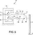
図5には、本発明による別の軸支時構造体70の幾何学的形態が概略図的に図示されている。図3及び図4の幾何学的形態におけるように、ツール支持軸に対する2つの継手は、共に、第一及び第二のアームによりこの二次元的空間にて動かすことができる。これらの幾何学的形態に反して、この幾何学的形態は、継手を操作するため線形アクチュエータのみを採用する。
【0034】
第一のアームは、基部のような静止支持体に接続された一端と、x軸線方向に向けて直線状に動くことのできる第一の線形部材73に接続された第二の端部とを有する第一のリンク71を備えている。第二のリンク74は、第一の線形アクチュエータ73に接続された一端と、x軸線方向に直交するy軸線(垂直)の方向に向けて直線状に動くことのできる第二の線形アクチュエータ75に接続された第二の端部とを備えている。この実施の形態において、x軸線及びy軸線は、互いに垂直であるが、垂直でなくてもよい。第三のリンク76は、第二の線形アクチュエータ75に接続された第一の端部と、第一の枢動継手78によりツール支持軸に対する第一の支持点にて第四のリンク77に接続された第二の端部とを備えている。第二のアームは、第一のリンク71が接続された同一の部材72のような、静止支持体に接続された一端と、x軸線方向に向けて直線状に作用することのできる第三の線形アクチュエータ81に接続された第二の端部とを有する第五のアームを備えている。第六のリンク82は、第三の線形アクチュータ81に接続された一端と、y軸線方向に向けて直線状に動くことのできる第四の線形アクチュエータ83に接続された他端とを有している。このように、第三の線形アクチュエータ82は、第一の線形アクチュエータ73に対して平行な経路内を動き、また、第四の線形アクチュエータ73は、第二の線形アクチュエータ75に対して平行で且つ第三の線形アクチュエータ81の経路に対して垂直な経路内を動く。更に、第一及び第二の線形アクチュエータの動作経路は、動作経路により及び第三並びに第四の線形アクチュエータにより、画成された面に対して平行な面を画成する。しかし、第三及び第四の線形アクチュエータの移動経路は、これらは平行でないように互いに対してある角度を為すようにすることができ、第三及び第四の線形アクチュエータ81、83の移動経路は、第一及び第二の線形アクチュエータ73、75の移動経路に対して及び第一及び第二の線形アクチュエータの移動経路により画成された面に対して平行である必要はない。第七のリンク84は、第四の線形アクチュエータ83に接続された一端と、第二の枢動継手85により第二の支持点にて第四のリンク77に接続された他端とを有している。第一及び第二の継手78、85の移動面に直交するz軸線方向に移動可能な第五の線形アクチュエータ86(軸挿入アクチュエータ)が第四のリンク77に取り付けられ且つツール支持軸11を支持する。図5において、z軸線は、第一の継手78及び第二の継手85を接続する直線に対して平行であるが、異なる方向に伸びるようにしてもよい。
【0035】
第一及び第二の継手87、85の各々は、第四のリンク77が第三及び第七のリンク76、84に対してピッチ及びヨー動作するのを許容し得るように第三及び第七のリンク76、84に対する第四のリンク77の2度の回転自由度を許容することができる。継手78、85の一方は、第四のリンク77がピッチ及びヨー動作に加えて、回動動作することを可能にし得るように、3度の自由度を提供することができるが、リンク76、84は、空間内で一定の方向を保つため、第三の回転自由度は必要ない。継手78、85は、継手が空間内の平行な面内を動くとき、継手の間の距離が変更可能であるように配置されている。例えば、継手の一方(図5の第二の継手85)が、第四のリンク77の長さ方向に向けて第四のリンク77に対して並進しないように固定することができる一方、他方の継手(この例において、第一の継手78)が、リンク77の長手方向に向けて第四のリンク77に対して並進可能である。これと代替的に、継手78、85の双方は、第四のリンク77に対して並進しないように固定することができ、また、第四のリンク77は、継手78、85の間の距離を変化させることを許容する伸縮式構造体を備えることができる。
【0036】
線形アクチュエータのみにて継手78、85の双方を操作することに代えて、図3の構成の場合と同一の仕方にて回転アクチュエータ及び線形アクチュエータの組合せ体と共に、図5の継手の一方(第一の継手又は第二の継手の何れか一方)を操作することが可能である。例えば、継手78を操作する図5の構成要素71、73、74は、図3の構成要素51、53に相応する回転アクチュエータ及びリンクにより置換することができる。その結果、図3及び図5の複合的な構成となる。
【0037】
図6には、本発明による軸支持構造体100の幾何学的形態が図示されており、この場合、ツール支持軸11に対する1つの継手は、相応するアームにより二次元的空間内で移動させることができる一方、第二の継手は、別のアームにより三次元的空間内で移動させることができる。第一及び第二のアームの第一及び第二の回転アクチュエータ101、120は、それぞれ、フレーム102のような静止支持体に固着されている。第一の回転アクチュエータ101は、第一のリンク103をその軸線の周りで回転させることができる。第一のリンク103は、第一及び第二の線形アクチュエータ104、105に接続され、これら線形アクチュエータは、第一の回転アクチュエータ101の回転軸線に対して垂直で且つ互いに平行な直線内で作用可能である。第二のリンク106及び第三のリンク107の各々は、第一の線形アクチュエータ104及び第二の線形アクチュエータ105に接続された一端を有している。第四のリンク108は、継手109により第二のリンク106の一端に枢動可能に接続された第一の端部を有し、第五のリンク110は、継手111により第三のリンク107の一端に枢動可能に接続された第一の端部を有する。第五のリンク110の第二の端部は、第一の支持箇所にて継手114により第六のリンク113に枢動可能に接続され、この第六のリンクには、ツール支持軸11が固着されている。第四のリンク108の第二の端部は、第五のリンク110の両端の間に配置された継手112により第五のリンク110に枢動可能に接続されている。継手109、111、112の各々は、第一の回転アクチュエータ101の回転軸線に対して垂直な軸線の周りで1度の自由度を提供し、これら3つの継手の全ての回転軸線は、互いに対して平行で且つ線形アクチュエータ104、105の動作経路に対して垂直である。第二の回転アクチュエータ120は、第七のリンク121を回転軸線の周りで回転させる。運動力学を簡略化するため、この回転軸線は、第一の回転アクチュエータ101の回転軸線と整合させることが好ましいが、その2つの軸線は、整合させ又は平行としなくてもよい。第七のリンク121は、第三の線形アクチュエータ122に固着され、該第三の線形アクチュエータは、第二の回転アクチュエータ120の回転軸線に対して垂直な直線に沿って作用する。第八のリンク123は、第三の線形アクチュエータ122に接続された一端と、第二の支持箇所にて継手124により第六のリンク113に接続された他端とを有している。継手114、124の各々は、第六のリンク113が第五のリンク110又は第八のリンク123に対して少なくとも2度の回転自由度にて枢動することを許容する。例えば、継手114、124の一方に3度の回転自由度を提供し又は第六のリンク113の2つの部分が第六のリンク113の長手方向軸線の周りで互いに対して回転し得るように、回動継手を第六のリンク113内に形成することことにより、第六のリンク113の周りで測定した、リンク110、123の間の角度が変更可能であるように、第六のリンク113及び継手114、124が配置される。継手114は、第六の継手113の長手方向に向けて第六のリンク113に対して並進しないように固定されており、継手124は、第六のリンク113の長手方向に向けて第六のリンク113に対して並進し、継手114、124の間の距離を変更することができるようにする。これと代替的に、継手114、124の双方は、第六のリンク113に対して並進しないように固定することができ、また、第六のリンク113は、継手114、124の間の距離を変化させることを許容する伸縮式構造とすることができる。
【0038】
この幾何学的形態において、継手124及び継手109、111の各々は、二次元的空間、すなわち平面内で移動する。これに反して、継手114は、三次元的空間内を移動することができる。例えば、継手114は、継手111を静止状態に保ちつつ、第一及び第二の線形アクチュエータ104、105が第一の回転アクチュエータ101の回転軸線に向けて動くように制御することで図6に上方に移動可能である一方、継手114は、継手111を静止状態に保ちつつ、継手109を第一の回転アクチュエータ101の回転軸線から離れるように動かすように第一及び第二の線形アクチュエータ104、105を制御することにより、図6の下方に移動することができる。このため、別個の軸挿入アクチュエータを必要とせずに、継手124の動作面から継手114の距離を変化させることにより、ツール支持軸11をz軸線方向に移動させることができる。その結果、ツール支持軸11の上端付近の支持軸支持構造体110の寸法を縮小させて、狭小な空間内でツール支持軸11を操作することをより容易にする。
【0039】
図7には、本発明によるマニプレータの軸支持構造体100Aの別の可能な幾何学的形態が図示されている。この幾何学的形態は、図6の幾何学的形態と同様であるが、この形態は、三次元的空間内で2つの継手を操作することができる。しかし、図6の第八のリンク123に代えて、継手127により枢動可能に接続された、第八のリンク125及び第九のリンク126が採用されており、継手109、111、112の回転軸線に対して平行な軸線の周りで1度の回転自由度を提供する。第八のリンク125の一端は、第三の線形アクチュエータ122に固着され、第九のリンク126の一端は、継手128により第六のリンク113に枢動可能に接続され、この継手128は、第九のリンク126に対し第六のリンク113の少なくとも2度の回転自由度を提供する。図6の実施の形態と同様、第六のリンク113及び継手114、128は、第六のリンク113の軸線の周りで測定したリンク110、126の間の角度が任意の適当な構造を使用して変更可能であるように配置されている。図6の継手124と異なり、図7の継手128は、第六のリンク113の長手方向に向けて第六のリンク113に対して並進しないように固定されている。第八及び第九のリンク125、126の間の継手127は、二次元的空間内で移動する一方、継手128は、三次元的空間内で移動可能である。要するに、図6の継手124の並進自由度は、回転継手127、リンク126により置換されている。
【0040】
この幾何学的形態において、継手109、111、127の各々は、二次元的空間内で移動可能である一方、継手114、128の各々は、三次元的空間内で移動可能である。このため、図6の幾何学的形態と同様に、別個の軸挿入アクチュエータを採用せずに、ツール支持軸11をz軸線方向に移動させることができる。
【0041】
図7の幾何学的形態は、図6の幾何学的形態における継手124よりも簡単な構造を継手128に採用することができ、第六のリンク113に対して図6の継手124の並進動作に関係する摩擦は、解消できる。このため、図7の幾何学的形態は、図6の幾何学的形態よりもツール支持軸11により精巧な動作を生じさせることができる。
【0042】
図6及び図7の構造は改変して次のようにすることができる、すなわち、第一及び第二の線形アクチュエータ104、105の動作経路に直交する方向(垂直方向)に向けて第一のリンク103を並進させることのできる線形アクチュエータにより回転アクチュエータ101、120を置換し、また、この線形アクチュエータが第七のリンク121を第三の線形アクチュエータ122の動作距離に直交する方向(垂直方向)に並進させることができるようにする。
【0043】
図8には、本発明によるマニプレータの別の支持軸構造体140の幾何学的形態が概略図的に図示されている。この軸支時構造体140は、三次元的空間内でツール支持軸11を支持する1つの継手と、二次元的空間内の別の継手とを操作することができる。回転軸線を有する第一の回転アクチュエータ141がフレーム又は基部のような静止支持体に取り付けられている。第一のリンク142は、第一の回転アクチュエータ141に接続された第一の端部と、第一の回転アクチュエータ141の回転軸線から隔てられた継手144により第二の継手143の第一の端部に接続された第二の端部とを有している。第二のリンク143の第二の端部は、継手146により第三のリンク145を第一の端部に接続されている。第三のリンク145の第二の端部は、ツール支持軸11に対する継手148により第四のリンク147の一端に枢動可能に接続されている。ツール支持軸11は、第四のリンク147に固着されている。第二の回転アクチュエータ149は、第三の回転アクチュエータ150を回転軸線の周りで回転させる。運動力学を簡略化するため、第一及び第二の回転アクチュエータ141、149の回転軸線は整合されているが、これらを整合させ又は平行にしなくてもよい。第三の回転アクチュエータ150は、第二の回転アクチュエータ149の回転軸線に直交する回転軸線(垂直方向)の周りで第五のリンク151を回転させる。第五のリンク151は、第三の回転アクチュエータ150を回転軸線に直交し(垂直方向)且つリンク145の軸線に対して垂直な軸線の周りで1度の回転自由度を有する継手152により第三のリンク145に接続されている。回転軸線を有する第四の回転アクチュエータ160は、静止支持体に取り付けられている。図8において、第四の回転アクチュエータ160の回転軸線は、第一及び第二の回転アクチュエータ141、149の回転軸線と整合されているが、これら軸線は、整合させ又は平行としなくてもよい。第六のリンク161は、第四の回転アクチュエータ160に固着された一端と、直線状に作用する線形アクチュエータ162に固着された第ニの端部とを有する。この例において、線形アクチュエータ162の動作経路は、第四の回転アクチュエータ160の回転軸線に対して垂直であり、このため、リンク163における任意の点は平面内で移動するが、その代わり動作経路が第四の回転アクチュエータ160の回転軸線に対して垂直でないようにすることが可能である。第七のリンク163は、線形アクチュエータ162に接続された一端と、第四のリンク147に枢動可能に接続された第二の継手164に固着された他端とを有している。継手148は、その長手方向に向けて第四のリンク147に対して並進しないように固定されている。更に、継手148、164は、その間の距離が可変であるように配置されている。例えば、継手164は、その長手方向に向けて、第四のリンク147に対し並進可能であるか又は継手164は第四のリンク147に対して並進しないよう固定することができ、第四のリンク147は、伸縮式構造とすることができる。継手148、164の各々は、第四のリンク147が少なくとも2度の回転自由度にて第三のリンク145又は第七のリンク163に対して枢動するのを許容する。第四のリンク147及び継手148、164は、第四のリンク147の周りで測定したリンク145、163の間の角度が変更可能であるように更に配置されている。例えば、継手148、164の1つは、3度の回転自由度を提供するか又は継手148、164は、2度の回転自由度を有し、また、第四のリンク147を2つの部分に分割し、その2つの部分は第四のリンク147の長手方向軸線の周りで互いに対し回転可能である、第四のリンク147に追加的な回転継手(ロール継手)を組み込むことができる。
【0044】
継手144、146に対し多くの異なる構造を採用することができる。例えば、双方の継手は、3度の回転自由度(例えば、2つの球状継手又はその均等物)を有し、一つの継手は、2度の回転自由度(例えば、ジンバル継手又はその均等物)を有する一方、他方の継手は、3度の回転自由度(例えば、球状継手又はその均等物)を有し又はその双方が2度の回転自由度(例えば、2つの球状継手又はその均等物)を有し、別の継手(ロール継手)を第二の継手143内に組み込み、第二のリンク143の2つの部分が第二のリンク143の長手方向軸線の周りで互いに対し回転するのを許容するようにすることができる。
【0045】
この構成にて採用される5つのアクチュエータのうち、3つは静止型で、第三の回転アクチュエータ150及び線形アクチュエータ162は、その重心が可能な限り第二及び第四の回転アクチュエータ149、160のそれぞれ回転軸線に接近するように配置し、これら軸線周りの慣性動作が最小となるようにすることができる。このため、軸支持構造体140は、全体として、マニプレータの巧みさを増すという観点から望ましい小さい慣性力を有することができる。
【0046】
第一、第二及び第三の回転アクチュエータ141、149、150は、共に、三次元的空間内の任意の位置まで継手148を移動させることができる一方、第四の回転アクチュエータ160及び線形アクチュエータ162は、共に、継手164を二次元的空間内の任意の位置まで移動させることができる。継手148、164の位置は適切に制御することにより、ツール支持軸11を常に仮想的枢動点と整合させることができ、軸挿入アクチュエータを必要とせずに、ツール支持軸11をz軸線方向に移動させることができる。
【0047】
図7の実施の形態が得られるように図6の実施の形態を改変することができるのと同様の仕方にて、図8の実施の形態を改変し、リンク163に代えて、互いに枢動可能に接続された2つのリンク(図7のリンク125、126に相応する)を使用し、また、第二の継手164をリンク147に対して並進しないように固定された図7の継手128に相応する継手と置換することができる。
【0048】
本発明による軸支持構造体はその方向が図3乃至図8に図示したものに限定されず、垂直に対して任意の所望の方向とすることができる。例えば、図6の配置において、方向を180°反転させ、第一の回転アクチュエータ101、第一及び第二の線形アクチュエータ104、105が第二の回転アクチュエータ130及び第三の線形アクチュエータ122の下方にあるようにすることができる。
【0049】
図3乃至図8の構成に採用される線形アクチュエータ及び回転アクチュエータは任意の特別の型式に限定されない。採用可能な線形アクチュエータの例は、線形電気モータが、回転動作を線形動作に変換する動作変換機構(ボールスクリュー又はラック及びピニオンのような機構)に接続された回転モータ及び液圧又は空圧シリンダを含む。ツール支持軸が少数の方向とすればよいとき、ソレノイドのような、少数の相違する状態のみを有する線形アクチュエータを使用することができるが、垂直に対し連続的な角度範囲に亙ってツール支持軸を操作することが望まれるとき、線形アクチュエータは、実質的に連続的な位置及び力の制御を許容することが好ましい。色々な型式の線形アクチュエータのうち、リニア電気モータが特に適しており、特に、ツール支持軸の角度を精密に制御することが望まれる用途に適している。リニアモータは線形出力を発生させ、ボールスクリュー、ケーブル、又はその他の動作変換器(全てツール支持軸の正確な制御にとって有害である、バックラッシュ、大きい慣性力、大きい摩擦力を発生させる)を使用することを必要とせずに、軸支持構造の部分を直接駆動するためにこのリニアルータを使用することができる。このように、リニアモータは、ツール支持軸の高精度の操作を可能にする。更に、リニアモータの移動質量は、基本的に、モータの可動部分の動作範囲と実質的に独立している。これに反して、ボールスクリューに接続された液圧シリンダ又はモータを含む、殆んどのその他の型式の線形アクチュエータにとって、移動範囲の長いアクチュエータは、移動範囲が短いアクチュエータと比較して、回転及び/又は並進を受ける可動質量が大きい。このため、線形アクチュエータとして採用されるリニアモータは、移動質量及び慣性力を小さくしつつ、移動範囲を長くすることができる。リニアモータの更に別の利点は、摩擦が極めて小さいことであり、このことは、可動質量及び慣性力が小さいと共に、力の制御及び/又は位置制御を正確に行う平滑な動作を実現する観点からして極めて有益である。かかる低摩擦の結果、リニアモータは逆駆動可能となる。すなわち、リニアモータは、モータが作用させる力方向と反対の方向に作用する外力によって駆動することができる。逆駆動可能であることは、マニプレータを順応型にする点で外科手術用マニプレータにて有用なことである。このように、例えば、患者が意図しない筋肉の動きにより、外科手術中に動き且つマニプレータの一部分に力を作用させるならば、アクチュエータは、逆駆動して、マニプレータは硬い物として作用せずに、患者が作用させた力に対応して動くことを可能にする。このため、逆駆動可能性は、マニプレータの安全性を向上させる。交流ベクトル駆動線形モータのようなその他の多くの種類及び商標名のリニアモータが採用可能であるが、線形アクチュエータの特に好ましい例は、テキサス州、ウェブスターのトリロジー・システムズ(Trilogy Systems)及びカリフォルニア州、サンタクララのノーザンマグネチックス(Northern Magnetics)が製造するもののような永久磁石直流リニアモータである。図示した実施の形態において、本発明に採用されるリニアモータは、静止磁石軌道と、該磁石軌道に沿って可動の可動コイル装置とを備えているが、可動磁石と、静止型コイル装置とを備えるモータを採用することも可能である。
【0050】
回転アクチュエータは、また、1つの特定の型式に限定されない。ブラシレスストットレス直流モータは、トルクの変動及び焼付きを防止し又は最小にするのに特に適しているが、ステッパモータのようなその他の型式も使用可能である。モータが回転アクチュエータとして使用されるとき、モータは、バックラッシュ、摩擦及び慣性力を軽減し、モータにより加えられるトルクを直接制御する能力を向上させ得るように回転されるリンクに直結的に接続されることが好ましいが、減速歯車をモータとリンクとの間に配置することも可能である。
【0051】
アクチュエータの可動部分又はアクチュエータにより駆動される部材の位置を感知し、これにより、工具支持軸に対する継手の位置を決定することを可能にするセンサを色々なアクチュエータに設けることができる。機械的、磁気的、光学的又はその他の方法にて位置を感知するために多岐に亙る従来のセンサを使用することができる。適当なセンサの幾つかの例は、電位差計、線形可変の差動変圧器、光エンコーダ及びホール効果センサである。線形アクチュエータを精密に位置制御することが望まれるとき、10ナノメートル程度の精密な分解能にて位置を感知することができる点にて位置センサとして、ホログラフィック干渉計線形エンコーダが特に適している。採用可能であるホログラフィック干渉計線形位置センサの一例は、マサチューセッツ州、ナティックのマイクロE(MicroE)インコーポレーテッドが製造するものである。かかる線形位置センサは、細長い位置スケールと、位置スケールを可動に配置することのできるスロットを有する位置読取り機とを備えている。位置スケール又は位置読取り機を線形アクチュエータの可動部分に取り付けることができ、また、その2つの一方を静止型部材に取り付けることができる。位置読取り機は、位置読取り機に対する位置スケールの位置を表示する電気的出力信号を発生させる。回転アクチュエータと共に使用される適当な位置センサの一例は、マイクロEインコーポレーテッドが製造するホログラフィック干渉計光回転エンコーダである。
【0052】
同様に、アクチュエータにより加えられる力又はトルクを感知し、これにより、工具支持軸に加えられる力及びトルクを決定することを可能にするセンサを色々なアクチュエータに設けることができる。このセンサの情報をフィードバック制御ループにて使用し、ツール支持軸に加えられる力及びトルクを制御し及び/又は力を発生させることのできる入力制御装置と共に使用されるとき、これら力及びトルクを軸支持構造体を制御する外科医又は操作者にフィードバックすることができる。
【0053】
力及び/又はトルクを測定する任意の既知の方法は、アクチュエータが加える力又はトルクを感知するために採用することができる。適当な方法の1つの例は、構造部材に歪み計を取り付けることである。
【0054】
図9には、図7に図示した幾何学的形態を有する本発明によるマニプレータの1つの実施の形態が図示されており、このマニプレータは、2つの継手を三次元的空間内で移動させることができる。マニプレータは、一端に取り付けられた外科用ツール171を有するツール支持軸170と、ツール支持軸170を支持し且つ多数の自由度にて工具支持軸170を操作することのできるツール支持軸170を支持する軸支持構造体180とを備えている。
【0055】
軸支持構造体180は、床182に位置する状態で示した支持基部181を備えている。基部181には、基部に可動性を持たせるべくころ又は同様の部材を設けることができ又は基部静止型部材とすることができる。支持フレーム183は、基部181に取り付けられている。ツール支持部材170の動作範囲を拡大するため、基部181には、支持フレームを昇降させ又はその他の方法で移動させる機構を設けることができる。例えば、該基部は、静止型下方部分181aと、昇降させ且つ/又は下方部分181aを垂直軸線の周りで回転させることのできる上方部181bとを備えることができる。上方部181bは、液圧シリンダ、空圧シリンダ、上方部分181bに形成されたラックに係合するピニオンを介する等により、上方部分181bに駆動可能に接続された電気モータのような任意の適当な装置により、昇降させることができる。上方部分181bが下方部分181aに対し回転可能であるとき、この上方部分は、モータのような駆動機構により回転させることができ又は手動で回転させることができる。所望のとき、上方部分181bが回転するのを解放可能に防止すべく機械的ロックを設けることができる。
【0056】
フレーム183は、互いに整合させる回転軸線を有するブラシレス直流モータを備える第一及び第二の回転アクチュエータ185、200を有する第一及び第二のアームを支持している。回転アクチュエータの各々には、その出力軸の回転位置を感知すべく図示しないエンコーダ又はその他の型式の回転位置センサを設けることができる。回転アクチュエータには、また、アクチュエータの出力トルクを感知するトルクセンサを設けることもできる。
【0057】
第一の回転アクチュエータ185の主力軸は、第一及び第二の線形アクチュエータ187、188が取り付けられたフレーム186に接続されている。第一の線形アクチュエータ187は、該第一のリンク190の長手方向に第一のリンク190を並進させることができ、第二の線形アクチュエータ188は、第二のリンク191の長手方向に第二のリンク191を並進させることができる。線形アクチュエータ187、188の双方は、第一の回転アクチュエータ185の回転軸線に対し垂直な方向に作用する。第一のリンク190の一端は、継手193により第三のリンク192の第一の端部に枢動可能に接続され、第二のリンク191の一端は、継手195により第四のリンク194の第一の端部に枢動可能に接続されている。第四のリンク194の第二の端部は、継手198により支持フレーム197に枢動可能に接続され、第三のリンク192の第二の端部が継手196によりその両端の間で第四のリンク194に枢動可能に接続されている。
【0058】
第二の回転アクチュエータ200は、第二の回転アクチュエータ200の回転軸線の周りで第三の線形アクチュエータ201を回転させる。第三の線形アクチュエータ201は、第五のリンク205を第二の回転アクチュエータ200の回転軸線に対し垂直な方向に並進させることができる。第五のリンク205の一端は、継手207により第六のリンク206の第一の端部に枢動可能に接続されている。第六のリンク206の第二の端部は継手208により支持フレーム197に枢動可能に接続されている。
【0059】
線形アクチュエータ187、188、201の各々は、細長い磁石軌道187a、188a、201aと、磁石軌道に沿って並進可能なコイル装置187a、88b、201bとを有するブラシレス直流リニアモータであるが、上述したように、コイル装置を静止型とし、磁石軌道がコイル装置に対し並進可能であるようにすることができる。コイル装置の各々は、相応する磁石軌道又はリニアモータに内蔵させたベアリングにより直接的に支持することができ又は磁石軌道に対し平行に伸びる線形ベアリングのような、リニアモータと別個に製造された部材によって支持することができる。ボールスライド又は往復運動型線形スライドが線形ベアリングとして特に適しており、それは、該スライドは、摩擦率を極めて小さくすることができるからである。適当なボールスライドの例は、日本のTHK株式会社から又はコネチカット州、デルトロン・プレシジョン(Deltron Precision)インコーポレーテッドから入手可能なものである。線形ガイドの摩擦率が小さいことは、リニアモータ(従って、ツール支持軸の継手)が極精密な増分量にて移動することを可能にし、その結果、ツール支持軸の方向を極精密に制御し且つ自動的に逆駆動である点にて極めて有益である。低摩擦であることは、ツール支持軸170に加わる力を制御する制御装置の能力をも向上させる。第一、第二及び第五のリンクの各々は、コイル装置の1つにより支持された片持ち部として概略図的に図示されているが、このリンクは、任意のその他の適当な方法で支持することができる。例えば、リンクの各々は、コイル装置と同一の仕方にて線形ベアリングの可動部分により支持することができる。
【0060】
継手198、208の各々は、第四及び第七のリンク194、206に対し支持フレーム197の少なくとも2度の回転自由度を提供し、支持フレーム197は、これら軸線に対してピッチ及びヨー動作が可能である。更に、継手198、208の1つは、3度の回転自由度を提供し、支持フレーム197がリンク194、206の1つに対し転がり可能であるようにすることができる。例えば、継手の1つは、ジンバル継手又はその均等物とすることができる一方、他方の継手は、球状継手又はその均等物とする。これと代替的に、双方の継手198、208は2度の回転自由度を有し、ロール継手を支持フレーム197に組み込むことができ、その2つは、支持フレーム197の2つの部分が支持フレーム197の長手方向軸線の周りで互いに対し回転するのを許容する。
【0061】
ツール支持軸170は、支持フレーム197に対し静止した状態で図示されているが、この軸を可動であるようにしてもよい。以下により詳細に説明するように、ツール支持軸170は、支持フレーム197から容易に取り外し可能であり、ツール支持軸170を交換し又は滅菌処理することが可能であるようにすることが有益である。ツール支持軸170の長手方向軸線は、継手198、208の中心を接続する線からずらした状態で図示されているが、この軸線はこの接続線と一致するようにしてもよい。
【0062】
マニプレータの構造及び運動力学を簡略化するため、リンクの全ては直線状の部材であり、第一、第二及び第五のリンク190、191、205は、図面の面に対し垂直な平行面内で相応する線形アクチュエータにより駆動される。しかし、リンクの形状は任意であり、第一、第二及び第五のリンクは平行でない面内で動くようにすることができる。
【0063】
回転アクチュエータ185、200の回転軸線が互いに同軸状であるならば、互いに対するリンクの位置を変更せずに、同一方向に回転アクチュエータ185、200を同時に作動させるか、又は回転アクチュエータを不作動にし手でツール支持軸170をこれら軸線の周りで旋回させることができる。このようにして、ツール支持軸170を旋回させるとき、リンクの相互の動きを防止するため、係止部材を設けることができる。例えば、線形モータのコイル装置187b、188b、201bには、これらコイル装置を相応する磁石軌道に対して解放可能に固定することを可能にし得るように係止機構を設けることができる。回転アクチュエータ185、200が非整合の軸線を有するならば、基部181の上方部分181bを下方部分に対して垂直軸線の周りで回転可能であるようにすることが望ましい。この場合、ツール支持軸170は、基部181の上方部分181b及び該上方部分により支持された全ての部材を回転させることにより、垂直軸線の周りで回転させることができる。
【0064】
線形アクチュエータ187、188には、ツール支持軸170の重量、及び取り付けられた任意の追加的なアクチュエータ又はその他の構成要素の重量による程度の重力を加えることができる。この重力の荷重は、アクチュエータ187、188により完全に支持するか、又はこの荷重を釣り合わせ得るようにリンク190、191とフレーム186との間に釣り合せ機構を追加することができる。この目的のため、一定力ばね、低摩擦空気シリンダ及び同様の装置を含む任意の既知の釣り合せ機構を採用することができる。
【0065】
アクチュエータにより付与された力又はマニプレータの色々な部分に作用する力を感知するため、力センサを色々な位置に取り付けることができる。当該実施の形態において、継手193、195、207の各々には、線形アクチュエータ187、188、201の各々により加えられた力を軸方向に感知する力センサが設けられる。図23は、継手193、195、207に接続されたリンクの一部分の等寸法であり、図24乃至図26は、継手195の力センサの色々な部分の図である。継手193、207に対する力センサは同様の構造とすることができる。これら図に図示するように、継手195は、リンク194の端部に取り付けられたベアリングに回転可能に係合し得るようにその一側部にて支持された軸195bを有するプレート195aを備えている。継手195は、フレーム210を通じてリンク191により支持され、このフレームには、リンク191に加えられた軸方向力に起因する歪みを感知する1つ又は2つ以上の歪み計が取り付けられる。フレーム210は、ボルト、溶接又はその他の適当な手段によりリンク191に固着された外側の矩形のリム211を有している。フレーム210は、リム211に固着されたプレート212を更に備えており(例えば、リム211及びプレート212を互いに一体に形成し又は別個の部材とすることができる)、また、複数の脚部を画成する複数の開口部212aを有している。図示したプレート212は、十字形の形状にて垂直脚部212bに交差する2つの垂直脚部212b及び2つの水平脚部212cを有する。継手195は、継手195に加えられた力を脚部で抵抗することができるように、フレーム210に接続されている。例えば、図示した継手195は、軸195bと反対側のプレート195aの側部から伸びる軸195cを有し、また、フレーム210のプレート212の中央開口部212dを通って進む。軸195cは、ナット213又はその他の締結具、接着又は継手195に加えられる力をフレーム210に伝達することを可能にするその他の所望の方法にてプレート212に固着することができる。軸195cは、フレーム210の開口部212dと相互に嵌まる一部分を備え、継手195がフレーム210に対し適正に整合することを保証することができる。例えば、図示した軸195cは、開口部212dに形成された突起と係合するスロット195dを有する。
【0066】
付与された荷重を測定するときに使用するため、任意の数の歪み計をフレーム210に取り付けることができる。当該実施の形態において、付与された荷重に起因する歪みを感知する2つの歪み計214a(荷重感知型歪み計と称される)が図26に図示するように、垂直脚部212bの後方面(リンク191に面する側部)に取り付けられており、また、更に温度補償用の2つの歪み計214b(その一方のみを図示)がフレーム210の外側リム211の垂直側面のように、マニプレータが作動する間、実質的に応力無しのフレーム210の部分に取り付けられる。例えば、リム211の反対側部の垂直側面に他の温度補償歪み計214bを取り付けることができる。4つの歪み計214a、214bは、ホイートストーンブリッジを形成し得るように互いに接続することができ、垂直脚部212bにおける歪み計214aの各々は、温度補償歪み計214bの1つと電気的に直列に接続される。従来の方法にて、ホイートストーンブリッジに電圧を印加することができ、更に、ホイートストーンブリッジの出力信号は、歪み計が受ける歪みの示すものである。
【0067】
リンク191の長手方向に向けてフレーム210の中心に力が加えられたとき、荷重感知歪み計214aの各々には、等しく、張力又は圧縮力が加わり、また、ホイートストーンブリッジの出力は、付与された力に比例する。力が垂直脚部212bの軸線方向に向けてフレーム210の中心に付与されるならば、荷重感知歪み計214aの1つには張力が加わる一方、その他方には圧縮力が加わる。2つの荷重歪み計214aからの信号は、互いに打消し合い、ホイートストーンブリッジの出力は実質的に零となる。水平脚部の軸線の周りでフレーム210にモーメントが加えられるならば、荷重感知歪み計214aは、等しく且つ反対方向に歪みが加わり、このため、この場合にも、ホイートストーンブリッジの出力は実質的に零となる。リンク191の長手方向軸線の周りで加えられたトルク、垂直脚部212bの軸線の周りで加えられたトルク、及び水平脚部212cの軸線に沿って加えられた力は、荷重感知歪み計214aに何ら顕著な変形を生じさせず、このため、実質的に、ホイートストーンブリッジの出力に影響を与えない。このように、図示した構成は、線形アクチュエータ181により付与された力である、リンク191の軸方向への力を感知することができ、リンク191又は継手195に作用する他の全ての力を無視することができる。
【0068】
フレーム210は何ら特定の形状に限定されず、開口部212a又は脚部212b、212cを形成しなくてもよい。しかし、2つの垂直脚部212b及び2つの水平脚部212cを有する図示した実施の形態は便宜であり、それは、その幾何学的簡略さのため、荷重感知歪み計214aにより測定された歪みを基にして継手195に作用する軸方向荷重を簡単な方法にて計算することができるからである。
【0069】
荷重感知歪み計214aにより安全に測定することのできる歪み計の範囲において、継手195によりフレーム210に加わる荷重をフレーム210の中心に局部的に作用させることが好ましく、このため、荷重は、フレーム210の周縁ではなくて、完全にフレーム210の脚部により抵抗を受けるようにすることが好ましい。それは、この場合、測定された歪みと加えられた荷重との関係を計算することがより容易であるからである。しかし、加えられた荷重によるフレーム210の変形が過度に大きいならば、脚部212b又はフレーム210上における荷重感知歪み計214a自体が損傷する可能性がある。
【0070】
かかる損層を防止するため、荷重が加えられるフレーム210の部分は、変形程度が増すに伴い、面積が増すような、図示した力センサの構造とされている。力センサの分解等寸法図である図24及び図25に図示するように、座金のような、2つのスペーサ215、216は、フレーム210のプレート212の両側部にて継手195の軸195cの周りに配置され、プレート217のような、内側スペーサ216よりも大きい表面積を有する部材は、内面216に隣接する軸195c上に取り付けられる。継手195に作用する荷重が存在しないとき、2つのスペーサ215、216は、継手195のプレート195a及びプレート217をフレーム210のプレート212から分離した状態に保つ。特定レベル以下の荷重がリンク191の両軸方向に向けて継手195に加わると、継手195のプレート195a及びプレート217は、フレーム210に接触せず、このため、荷重は開口部212d付近の領域内にのみフレーム210に加えられ、荷重は、実質的に完全にフレーム210の脚部により抵抗を受ける。フレーム210に加わる軸方向荷重が、歪み計212b又はフレーム210を損傷させるであろうレベルよりも小さく選んだ、高レベルに達すると、継手195のプレート195aはフレーム210のプレート212に接触し、軸方向荷重は、例えば、脚部を取り巻くプレート212の周縁を含む、フレーム210のより大きい領域に亙って分配され、これにより、フレーム210の変形が損傷を生じるレベルに達するのを防止する。同様に、反対の軸方向へ向けてフレーム210に加わる荷重が歪み計212b又はフレーム210を損傷させるであろうレベルよりも低いように選んだ特定のレベルに達したとき、プレート217は、プレート212の内側部(水平脚部212c及び/又はプレート212の周縁のような)に接触し、歪み計212b又はフレーム210の損傷を防止すべくプレート212のより広い部分に亙って軸方向荷重を分配する。
【0071】
マニプレータに作用する力又はマニプレータによって加えられる力を感知するため、多くの他の装置を使用することができる。例えば、歪み計又はその他の力センサをアクチュエータ又はマニプレータのリンクに直接、取り付けることができる。
【0072】
図10乃至図13には、図5に図示したものと同様の幾何学的形態を有する、本発明によるマニプレータの1つの実施の形態が図示されている。図10は、この実施の形態の等寸法図である。図11は側面図、図12は線形アクチュエータ付近のマニプレータの部分の拡大図、図13はツール支持軸を支持するマニプレータ部分の拡大図である。これらの図面に図示するように、マニプレータは、その下端に取り付けられたツール171を有するツール支持軸170と、ツール支持軸170を可動に支持する軸支持構造体220とを備えている。軸支持構造体220は、床又はその他の支持面上に配置された支持基部221を有している。図9の実施の形態の支持基部181と同様に、支持基部221は、可動部分を備えることができる。例えば、支持基部は、静止型の下方部分221aと、図9に関して説明したように、下方部分221aに対し垂直軸線に沿って昇降させ且つ/又は回転させることのできる上方部分221bとを備えることができる。
【0073】
第一のフレーム222は、基部221の上方部分221bの頂部に取り付けられる。第二のフレーム223は、図面にて水平であるが、水平線に対し傾斜させることのできる軸線224の周りで回転可能に第一のフレーム222により支持されている。第二のフレーム223は、フレーム222、223の1つに取り付けられたモータ又はその他の駆動機構によって又は手動で回転させることができる。第二のフレーム223は、回転しないように解放可能に係止すべくフレーム222、223の1つにロックを設けることができる。第二のフレーム223は、第一のアームの上方組みの線形アクチュエータ230、235と、第二のアームの下方組みの線形アクチュエータ250、255とを支持し、この第二のアームによりツール支持軸170は並進及び枢動可能となる。第一の組みのアクチュエータは、直線に沿って第一の方向に可動である可動部分を有する第一の線形アクチュエータ230と、第一の線形アクチュエータの可動部分の上に取り付けられ、第一の方向と直交する方向(垂直方向)に向けて第一の線形アクチュエータ230に対し可動である可動部分を有する第二の線形アクチュエータ235とを備えている。第一のリンク238は、第二の線形アクチュエータ235の可動部分に固着されている。同様に、第二の組みのアクチュエータは、第三の方向に可動である可動部分を有する第三の線形アクチュエータ250と、第三の線形アクチュエータ250の可動部分に取り付けられ且つ第三の方向と直交する方向(垂直方向)に向けて第三の線形アクチュエータ250に対して可動である可動部分を有する第四の線形アクチュエータ255とを備えている。第二のリンク258が第四の線形アクチュエータ255の可動部分に固着されている。この図面において、第一及び第二の方向は互いに垂直であり、第三及び第四の方向は互いに垂直であり、第一の方向は第三の方向に対し平行で、第二の方向は第四の方向に対し平行であり、このため、線形アクチュエータの可動部分は全て平行な面内を移動する。しかし、図5に関して説明したように、これら方向は、互いに対し他の角度となるようにすることができる。線形アクチュエータは、任意の所望の型式とすることができる。図示した実施の形態において、線形アクチュエータ230、235、250、255の各々は、細長い磁石軌道231、236、251、256を有するブラシレスリニア電気モータと、磁石軌道に沿って直線状に可動であるコイル装置232、237、252、257とを有する可動部分を備えている。第二の線形アクチュエータ235の磁石軌道236は、第一の線形アクチュエータ230のコイル装置232に固着され、第四の線形アクチュエータ255の磁石軌道256は、第三の線形アクチュエータ250のコイル装置252に固着されている。更に、第一のリンク238は、第二の線形アクチュエータ235のコイル装置237に固着され、第二のリンク258は、第四の線形アクチュエータ255のコイル装置257に固着されている。線形アクチュエータの各々には、磁石軌道に対するアクチュエータのコイル装置の位置を感知するエンコーダ又はその他の位置センサを設けることができる。また、線形アクチュエータの各々にはアクチュエータの出力を感知する力センサを設けることもできる。この装置の各々は、相応するモータの磁石軌道によってのみ支持されているとして図示され、リンク238、258は、第二及び第四の線形アクチュエータ235、255のコイル装置によってのみ支持された状態で図示されている。しかし、これら部材の各々は、別個の線形ベアリングのような線形アクチュエータ自体以外の部材によって支持することができる。
【0074】
線形アクチュエータから分離された第一及び第二のリンク238、258の端部は、第一及び第二の継手240、260によりそれぞれ支持フレーム270に接続されており、これら継手の各々は、相応するリンクに対して支持フレーム270の2度の回転自由度を提供することができる。継手240、260の一方は、3度の自由度を提供することができるが、各リンク238、258の各々は、空間内で一定の方向を保つため、3度の自由度は不要である。継手240、260間の距離は、変更可能である。例えば、継手240、260の一方は、支持フレーム270に対して並進しないように固定することができる一方、他方の継手は、支持フレーム270に対して並進可能である。これと代替的に、両方の継手240、260を支持フレーム270に対して並進しないように固定することができ、継手240、260に接続した支持フレーム270の部分は伸縮式の構造とすることができる。継手は、構造の点にて、図9の実施の形態と類似している。この例において、第一の継手240は、軸線Aの周りで回転し得るように支持フレーム270のロッド271の周りに摺動可能に嵌着するスリーブ242に枢動可能に接続されたヨーク241と、該ヨーク241に接続され且つ第一のリンク238の一端に嵌着し且つ固着されたカラー243とを備えている。カラー243は、ヨーク241が軸線Aに対して垂直な軸線Bの周りで回転するように、ヨーク241を回転可能に支持する内側ベアリングを備えている。第二の継手260は、同様に、スリーブ262に枢動可能に接続されたヨーク261を備えており、該ヨーク261は、カラー263により回転可能に支持され、該カラー263は、第二のリンク258に嵌着し且つ第二のリンク258の一端に固着されている。スリーブ262は、ブッシュ264、ボールベアリング、又は支持フレーム270のロッド271に固着された同様の部材に回転可能に取り付けられている。スリーブ262は、ロッド271の長手方向軸線の周りでブッシュ264上にて回転することができるが、ロッド271の長手方向への並進は防止される。
【0075】
支持フレーム270は、軸を挿入し得るように線形アクチュエータ280を支持する一方、該軸は、ツール支持軸170をz軸線方向に動き得るように支持する。線形アクチュエータ280は、それ以前の実施の形態に関して説明した型式の任意のものとすることができる。図示した線形アクチュエータ280は、支持フレーム270に固着された細長い磁石軌道281と、該磁石軌道281に沿ってz軸線方向に可動であるコイル装置282とを有するリニア電気モータである。ツール支持軸7170は、コイル装置により並進されるようにコイル装置に固着されている。
【0076】
ツール支持軸170の下端が患者の体内に挿入されたとき、ツール支持軸170は、典型的に、線形アクチュエータによってのみ操作される一方、ツール支持軸170を患者の体内に挿入しないとき、ツール支持軸170の粗位置決めのため、通常、基部221の上方部分221bの並進/回転及び第一のフレーム222に対する第二のフレーム223の回転が使用される。第二のフレーム223が第一のフレーム222に対して回転し得ることは、特に有用なことであり、それは、ツール支持軸170が垂直線に対し任意の角度を取ることを可能にするからである。例えば、ツール支持軸170は、ツール支持軸170の他の部分よりも上方に配置されたツール171に対して水平又は上下逆になる位置まで動かすことができる。
【0077】
図14には、図8に図示したものと同様の幾何学的形態を有する、本発明のマニプレータの1つの実施の形態が図示されている。該マニプレータは、その下端にてツール316を支持するツール支持軸315と、ツール支持軸315を可動に支持する軸支持構造体290とを備えている。軸支持構造体290は、ツール支持軸315に対する継手を三次元的空間内で操作することのできる上方部分291と、ツール支持軸315に対する別の継手を二次元的空間内で操作することのできる下方部分310とを備えている。これら上方部分291及び下方部分310は、通常、図9及び図10に図示したもののような基部の如き、図示しない支持構造体に取り付けられている。
【0078】
上方部分291は、第一乃至第三の回転アクチュエータ292、293、294と、第一乃至第三のリンク296、298、300とを備えている。第一の回転アクチュエータ292は、第三の回転アクチュエータ294を軸線の周りで支持するフレーム295を回転させることができる。第二の回転アクチュエータ293は、第二の回転アクチュエータ293の回転軸線と同心状の円の円弧に沿った任意の点に第一のリンク296の第一の端部を位置決めすることができる。第三の回転アクチュエータ294は、第一及び第二の回転アクチュエータ292、293の軸線に対し垂直で且つ第三のリンク300の長手方向軸線に相応する軸線の周りで第三のリンク300を回転させることができる。第一及び第二の回転アクチュエータを互いに積み重ねることを許容するため、第二の回転アクチュエータ293は中空であり、第一の回転アクチュエータ292の出力軸が第二の回転アクチュエータ293を通って伸びるようにすることができる。例えば、第二の回転アクチュエータ293は、コアの周りに配置されたロータを有する従来の中空コアモータとすることができる一方、第一の回転アクチュエータ292は、その中心にロータを有し且つロータに固着され、第二の回転アクチュエータ203の中空コアを通って伸びる出力軸を有するモータとすることができる。第一のリンク296の一端は、継手297により第二の回転アクチュエータ293の回転部分に枢動可能に接続され、第一のリンク296の他端は、別の継手299により第二のリンク298の一端に枢動可能に接続されている。2つの継手297、299の一方は、球状継手(ボール継手のような)又はその均等物である一方、2つの継手の他方は、自在継手(フックの継手のような継手)である。第三のリンク300の外端は、第二のリンク298の両端間にてピン継手301により枢動可能に接続されている。第二のリンク298の第二の端部は、ツール支持軸315に対して並進しないように固定された継手302によりツール支持軸315に枢動可能に接続されている。軸支持構造体290の下方部分310は、第四の回転アクチュエータ311と、該第四の回転アクチュエータ311によりその回転軸線の周りで回転させることのできる線形アクチュエータ312とを備えている。運動力学を簡略化するため、第四の回転アクチュエータ311の回転軸線は、第一及び第二の回転アクチュエータ292、293の回転軸線と整合されることが好ましいが、そうする必要もない。線形アクチュエータ312は、第四の回転アクチュエータ311の回転軸線に対して直交する方向(垂直方向)に第四のリンク313を並進させることができる。該線形アクチュエータ312は、任意の適当な型式とすることができる。例えば、これは、第四の回転アクチュエータ311の出力軸に固着された磁石軌道と、第四のリンクの313の一端に固着された可動の磁石装置とを有する、図9に図示したもののような、リニアモータとすることができる。第四のリンク313の外端は、第二の継手314によりツール支持軸315に枢動可能に接続され、該第二の継手は、ツール支持軸の長手方向に向けて該ツール支持軸315に対し並進可能である。
【0079】
第一及び第二の継手302、314の各々は、ツール支持軸315が第二又は第四のリンク298、313に対して少なくとも2度の自由度にて枢動することを許容し、ツール支持軸315のピッチ及びヨー動作を許容し、また、継手302、314の1つは、ツール支持軸315が相応するリンクに対して3度の自由度にて枢動することを許容し、ツール支持軸315が転がるのを許容する。例えば、継手302、314の一方は、ジンバル継手又はその均等物とする一方、他方の継手は、ボール継手のような球状継手又はその均等物とすることができる。これと代替的に、継手302、314の双方が2度の自由度を有し、ロール継手をツール支持軸315内に組み込むことができる。継手302、314との間の距離は、継手が空間内で移動するに伴い変化するようにすることができる。例えば、継手314は、ツール支持軸315が継手314に対してその長手方向に移動するのを許容し且つ/又はツール支持軸315は伸縮式の構造を備えるようにすることができる。
【0080】
本発明によるマニプレータにおいて、ツールは、ツール支持軸に対して一定の位置にてツール支持軸上に取り付け、ツールがツール支持軸を全体として移動させることにより操作される。これと代替的に、ツールは、ツール支持軸に対するその方向が遠隔制御装置により1度又はより大きい自由度にて調節可能な仕方にてツール支持軸に接続することができる。例えば、ツール支持軸は、ツールを支持し且つツールがツール支持軸に対して枢動するのを可能にし、1又はそれ以上のピッチ、ヨー及びロール動作を行い得るようにするリスト機構を備えることができる。当該分野には多岐に亙るリスト機構が存在し、ツールの所望の動作を可能にする任意の型式のものを採用することができる。図15は、ジンバル状の構造を有する簡単で軽量なリスト機構330を採用するツール支持軸320の1つの実施の形態の概略図的な断面図である。図16は、ツール支持軸内に取り付けられたリスト機構の平面図である。これら図面に図示するように、ツール支持軸320は、円形のような任意の所望の横断面形状を有する中空の細長い管321を備えることができる。その下端にて、管321は、ツール322を支持する支持管331と、支持管331を取り巻くリング340とを有するリスト機構330を支持している。支持管331は、第一の軸線333の周りで枢動し得るようにリング340により枢動可能に支持され、また、リング340は第一の軸線333に直交する第二の軸線342の周りで管321に対して枢動可能であるようにツール支持軸320のツール支持軸管321により枢動可能に支持されている。運動力学を簡略化するため、また、モーメントを小さくするため、第一の軸線333及び第二の軸線342は互いに垂直であり且つ直交するようにすることが好ましいが、これらは、垂直又は直交するようにする必要はない。
【0081】
支持管331は、第一の軸線333の周りで枢動させることができ、また、リング340はリスト機構330と、ツール支持軸320の上端に配置された相応するアクチュエータ355との間に接続された複数の細長いコネクタ350により第二の軸線342の周りで枢動することができる。コネクタは、張力状態,圧縮状態又はその双方にて作用する設計とすることができる。このように、伝達する必要のある力の型式に依存して、コネクタ350は、例えば、ロッド、バー、ワイヤー、チェーン、ベルト、ばね又は同様の部材とすることができる。当該実施の形態において、コネクタ350の各々は、張力状態及び圧縮状態の双方にて作用可能であり、また、ツール322を第一及び第二の軸線の周りで枢動させるためには、2つのコルクタ350及び2つのアクチュエータ355のみがあればよい。コネクタ350の各々が、張力状態においてのみという如く、単一方向にのみ作用可能であるならば、ツール322を2つの軸線の周りで枢動させるためには、多数のコネクタ及びアクチュエータが必要とされ、例えば、支持管331及びリング340の各々に対して2つのコネクタ及び2つのアクチュエータが必要となり、合計で4つのコネクタ及び4つのアクチュエータとなる。これと代替的に、支持管331及びリング340にこれらの部材を特定の回転方向に偏倚させる戻りばねが設けられるならば、4つではなくて、張力状態にて作用する2つのコネクタを使用することが可能である。別の代替例として、支持管331及びリング340は支持管331に取り付けられ且つ張力状態にて作用する3つのコネクタにより第一及び第二の軸線333、342の周りで枢動することができる。
【0082】
当該実施の形態において、コネクタ350の1つは,第一の軸線333から隔たった位置334にて支持管331にその下端が接続されており、他方のコネクタ350は、第二の軸線342から隔たった位置343にてリング340に接続されている。図16に図示するように、当該実施の形態において、1つのコネクタ350は、第二の軸線342と略整合された位置334にて力を付与し得るように支持管331に接続されており、他方のコネクタ350は、第一の軸線333と略整合した位置343にて力を付与し得るようにリング340に接続されている。しかし、コネクタ350が管331及びリング340に接続される位置334、343は、軸線342、333と整合させる必要はない。コネクタ350の各々は、枢動接続具により支持管331又はリング340に接続することが好ましい。それは、コネクタ350と支持管331又はリングとの間の角度は、支持管331又はリング340が第1の軸線又は第二の軸線の周りで枢動するときに、変化するからである。コネクタ350は、該コネクタが軸線の圧縮力を受けたときに屈曲するのを防止する任意の断面形状とすることができる。図17は、コネクタ350の横断面形状の一例を示す、ツール支持軸320の横断面図である。この例において、コネクタ350の各々は、該コネクタに対して屈曲に対するより大きい抵抗性を付与し得るようにその長さの少なくとも一部分に亙って円弧状の横断面を有している。その長さの少なくとも一部に沿って、コネクタ350の幅方向端縁は、ガイド322の間に受け入れられ、このガイドは、コネクタ350がツール支持軸320の長手方向に摺動するのを許容する一方、横方向への動きを拘束し且つコネクタの屈曲強度を更に増大させる。その上端及び下端にて、コネクタ350の断面形状は、円弧状の形状から、リスト機構330又はアクチュエータ355にコネクタ350を取り付けるのにより便宜な形状まで相違するものとすることができる。
【0083】
コネクタ350の1つを支持管331に接続し、コネクタ350の他方の管をリング340に接続することに代えて、その双方のコネクタ350を異なる位置にて支持管331に接続することができる。例えば、1つのコネクタ350を図16の位置334にて支持管331に接続することができ、また、別のコネクタ350を、第一の軸線333と整合させた,図16の位置336のような位置にて支持管331に接続することができる。
【0084】
支持管331に取り付けられ且つ張力状態にて作用する3つのコネクタにより、第一及び第二の軸線333、342の周りで支持管331及びリング340が枢動する構成において、コネクタは、多岐に亙る位置にて支持管331に取り付けることができる。例えば、1つのコネクタを第二の軸線342(図16の位置334のような位置にて)と整合して支持管331に取り付けることができ、別のコネクタを第一の軸線333と整合して(図16の位置336のような位置)支持管331に取り付けることができ、第三のコネクタを第一の軸線333及び第二の軸線342から隔たった位置(図16の位置337のような位置)にて支持管331に取り付けることができる。
【0085】
コネクタ350に対するアクチュエータ353は、回転動作を線形動作に変換する機構が設けられた線形アクチュエータ又は回転アクチュエータを含む、コネクタ350に軸方向力を付与することのできる任意の型式とすることができる。軸支持構造体に対する線形アクチュエータの場合と同様に、リニアモータが特に適している。アクチュエータ355には、アクチュエータ355の出力部分及び/出力を測定する位置センチ及び/又は力センサを設けることができる。
【0086】
図示したリスト機構330は、ツール322が第一の軸線及び第二の軸線の周りで枢動するのを許容するのみならず、ツール322が第一及び第二の軸線に対して直交する(垂直方向)ロール軸線の周りで転がり動作することをも許容する。ツール322がロール軸線の周りで回転し得ることは、ツール322が所定の作業に最も適した方向にツールを移動させることをより容易にし、また、リスト機構300をツール322の作業空間内で角度自在であるようにする。更に、ツールの型式に依存して、ツールが部材にトルクを加えることを可能にし、または、回転切断又は研磨動作を行うことを可能にすべく回転動作を使用することができる。ツール322は、ツール支持軸320に対するその方向が一定である場合でも、ロール軸線の周りで回転可能である。当該実施の形態において、ツール322は、ツール支持軸320内に配置され且つツール支持軸320の上端における回転アクチュエータ366とツール322との間を伸びるツールロール軸360により回転させることができる。ツール322は、支持管331に取り付けられたブッシュ335のような、ベアリングにより回転可能に支持されている。ツールロール軸360は、ツール支持軸の上端に接続されたブラシレス直流モータ又はその他の型式の電気モータのような任意の適当な型式の回転アクチュエータにより回転させることができる。ツール322が、第一の軸線及び第二の軸線の一方又はその双方の周りでツールロール軸360に対して枢動可能であるならば、ロール軸線がツールロール軸360と整合されていないとき、ツールロール軸360によりツール322を回転させることができるような仕方にてツール322のツーツロール軸360をツール322に接続することが好ましい。例えば、当該実施の形態において、ツールロール軸360の下端は自在継手365によりツール322に接続されている。ツールロール軸360は、例えば、その長さに沿った一点又はより多くの箇所にて図示しないベアリングにてツール支持軸320により回転可能に支持し、ツール支持軸320の管321に対する所望の位置にツールロール軸360を保つことができる。
【0087】
幾つかの場合、ツール322は、ツールを外科的に使用する間、操作される可動部品を備えることができる。可動部品を備えるツールの例は、鉗子、鋏、針ホルダ、クランプ及びステープルを含む。ツール322の構造に依存して、可動部品は、ツールを機械的に、空圧、液圧又は電気的に遠隔操作し得るように、ツールの支持管の上方部分又は外側まで伸びるケーブル、ロッド、空圧又は液圧管、又は電線のような、任意の機構によって作動させることができる。ツールを操作するケーブル、ワイヤー又はその他の部材は、ツールロール軸360の穴を貫通して伸びるようにするか、又はツールロール軸360の外側に沿って伸びるようにすることができる。
【0088】
当該実施の形態において、ツール322は、ツールロール軸360を貫通するコネクタ367により、又は可動部品とツール支持軸320の上端に配置されたアクチュエータ368との間の自在継手365により、作動させることのできる可動部品を備えている。該コネクタ367は、ツール322の構造に依存して、張力状態及び/又は圧縮状態にて作用するものとすることができる。例えば、ツール322は、引張り力を解放したとき、ツールを最初の位置に戻す、ツール322内のばねに抗して張力状態にて機能するコネクタ367により操作することができる。コネクタ367は、ツールロール軸360を回転させることができ、又はツールロール軸360が回転するとき、静止状態に止まるようにすることができる。該コネクタ367は、ツール322の長手方向軸線がツールロール軸360の長手方向軸線と整合されないときでさえ、ツール322を操作可能であることが好ましい。例えば、コネクタ367は、2つの軸線が整合されていないとき、曲がるか又はコネクタ367がある角度にて力を付与することを可能にする枢動継手により共に接続された硬い部分を備えることのできる、ケーブルのような任意の適当な型式のものとすることができる。リスト機構330の支持管331及びリング340を枢動させるアクチュエータ355と同様に、コネクタ367用のアクチュエータ368は、回転動作を線形動作に変換する機構により、コネクタ367に接続された線形アクチュエータ又は回転アクチュエータのような、任意の適当な型式とすることができる。
【0089】
図18は、本発明にて使用することのできるリスト機構370の別の例の概略図的な断面図である。このリスト機構370は、ブッシュ372を貫通するツール322を回転可能に支持する支持管371と、支持管371を取り巻く、プラスチック、紙、金属、又はその他の適当な材料から成る環状の隔膜373とを備えている。該隔膜373の内周は、その全周に亙って支持管371に固着され且つ好ましくは流体密な仕方にて密封され、また、隔膜373の外周は、その全周の周りでツール支持軸320の管321に流体密な仕方にて密封されている。隔膜373は、支持管371の重量を支えるのに十分に強力であるが、支持管371がピッチングし且つヨー動作し得るように第一及び第二の軸線の周りで支持管371が枢動するのを許容するのに十分、可撓性である。図示した隔膜373は、可撓性を持たせる環状の波形374にて形成されている。隔膜373の半径方向外側領域は、支持管371を取り巻く中央領域よりもより可撓性であることが好ましい。先の実施の形態にて採用されたものと同様の2つのコネクタ350が適当な角度(90°のような)だけ周縁方向に向けて互いに隔てられた位置にて支持管371に接続されている。コネクタ350の各々の上端は、コネクタ350をその長手方向に並進させることのできる相応する不図示のアクチュエータに接続される。1つのコネクタ350がその長手方向に並進されると、支持管371及びツール322は、第一の軸線の周りで枢動され、他方のコネクタ350がその長手方向に枢動されると、支持管371及びツール322は、第二の軸線の周りで枢動される。隔膜373がツール支持軸320の支持管371及び管321の双方に対して密封されているならば、隔膜373は、ツール支持軸320の内部と患者の身体の内部との間にてその何れかの方向に汚染物質を伝達することを防止することができる。リスト機構370を除いて、ツール支持軸320の構造は、図15に関して説明したものと同一とすることができる。
【0090】
ツールに付近におけるツール支持軸の少なくとも下方部分は、全体として、ツール支持軸を外科的に使用する前に、滅菌処理する必要はない。ツール支持軸の滅菌処理をより容易にするため。ツール支持軸の全体は、マニプレータの他の部分から取り外すことができる。図19乃至図21には、その可動部品を操作しつつ、ツール支持軸320を取り外し可能に支持することのできる構成が図示されている。この構成において、ツール支持軸320は、上述した軸支持構造体の任意のものを備えることができる軸支持構造体の支持フレーム270に取り外し可能に固着することができる。複数のアクチュエータ380A乃至380C及び390は、支持フレーム270に取り付けられている。第一及び第二の線形アクチュエータ380A、380Bは、例えば、図15又は図18に図示したものと同様の不図示のリスト機構に接続された2つのコネクタ350の線形動作を生じさせる。第三の線形アクチュエータ350Cは、リスト機構により支持された不図示のツールの可動部品を操作するコネクタ367の線形動作を生じさせ、回転アクチュエータ390は、ツールに接続されたツールロール軸360を回転させる。線形アクチュエータ380A乃至380Cの各々は、相応するコネクタに取り外し可能に係合する一方、回転アクチュエータ390は、ツールのロール軸360に取り外し可能に係合することができる。図20は、第一の線形アクチュエータ360Aの側面図である。他の線形アクチュエータ380B、380Cは同様の構造を備えることができる。線形アクチュエータ380Aは、円筒状のハウジング381と、該ハウジング381内の軸方向に可動の出力軸382とを有する直流のリニアサーボモータから成っている。モータは、円筒状である必要はないが、スペースを節約する観点からして、円筒状の形状が好ましいことがしばしば生ずる。この型式の円筒状のリニアサーボモータは、カリォルニア州、サンタクラリのノーザンマグネティックス(Northern Magnetics)のような多くの製造メーカから入手可能である。このモータは、可動磁石モータ又は可動コイル型の何れかとすることができるが、コイルにより発生された熱を飛散することが容易な観点からして可動磁石型が有利であり、それは、可動磁石モータのコイルは磁石外側に配置され、また、吸熱体の上に取り付けることができるからである。モータの可動部品をより円滑に並進させ得るようにするために、可動部品は線形ベアリング358の摺動部分387上に取り付けることができ、また、ベアリング385の静止部分386が支持フレーム270により支持されるようにすることができる。出力軸382は、各端部にて全体としてU字形の外形としたフレーム383に固着されている。該フレームは、支持フレーム270から離れる反方向に伸びる2つの平行な脚部を有する。下方脚部は、その外端にリセス部384が形成されている。各コネクタ350の上端は、リセス部384内に取り外し可能に受け入れられるような形状とされている。例えば、この実施の形態において、各コネクタ350の上端は、フレーム383のリセス部384内に嵌入するのに十分に小さい中間部分352を有するスプール形状部分351と、リセス部384よりも大きい直径を有する下方フランジ353とを備えている。スプール形状部分351がリセス部384内に挿入されたとき、フレーム383が出力軸382の長手方向に並進することは、フランジ353をフランジ383と当接関係にし、これにより、コネクタ350をその長手方向に並進させることになる。
【0091】
回転アクチュエータ390は、ローラ391が取り付けられた出力軸を有する。線形アクチュエータ380A乃至380Cのフレーム383がリスト機構に対する相応するコネクタ350、367の上端に係合し、ツールを操作すると、ローラ391は、基部ロール軸360の上面と摩擦係合状態となるように押され、ローラ391が回転すると、ツールロール軸360がその軸線の周りで回転する。ローラ391及び/又はツールロール軸360の外面を形成する材料は、十分な転がり接触が得られるように選ぶことができる。例えば、ローラ391は、高摩擦変形可能なゴムにて作ることができる。また、ローラ391は、ピニオンにて置換し、また、ツールロール軸360がピニオンと係合する歯車の歯をその外側に有するようにすることも可能である。
【0092】
使用後、直接的なツール支持軸320を軸支持構造体から除去し且つ清浄な軸と交換し、汚れたツール支持軸320は滅菌処理するか又は廃棄することができる。ツール支持軸320自体は何ら高価な部品を必要とせず、このため、この軸は、1回の使用後、使い捨て可能であるように十分に経済的に製造することができる。
【0093】
本発明によるマニプレータのアームは、物理的に、互いに独立的に可動である、すなわち、該アームは、1つのアームの動作が他方のアームを付勢して特定の仕方にて動くようにするように共に連結されていない。このため、その下端が患者の体内に挿入されたとき、ツール支持軸を仮想的枢動点との整合状態を保ちつつ、ツール支持軸の方向を調節するためには、2つ以上のアクチュエータの作動を調和させることが必要となる。ツール支持軸の何らかの動作のためには、人間の操作者が異なるアクチュエータの作動を手で調和させることが可能である。しかし、ツール支持軸の所望の動作を指令する人間操作者からの命令に基づいて複数のアクチュエータの作動を自動的に調和させることのできる電子式制御装置のような自動制御機構を採用することが通常、より容易である。
【0094】
図22は、本発明に従ってマニプレータと共に採用可能である制御装置400の一例のブロック図である。制御装置400は、汎用又は特殊目的コンピュータのような電子式制御装置401を含む。制御装置401は、位置センサ403から及び/又はマニプレータの色々な線形アクチュエータ及び/又は回転アクチュエータ404の力センサから入力信号を受け取る。制御装置401は、また、1つ以上の適当な入力装置402から入力信号を受け取り、この入力信号により操作者は、ツール支持軸により付与すべき所望の動作及び/又は力を指令する命令を制御装置401に提供することができる。ジョイスティック、触覚インターフェース(操作者への力をフィードバックすることのできる入力装置)、キーボード、テープ記憶装置又はその他の記憶装置、足踏みペダル、マウス、デジタル化器、コンピュータグローブ又は音声操作制御装置のような多岐に亙る入力装置402を採用することができる。採用可能な触覚インターフェースの一例は、「平行機構(Parallel Mechanism)」という名称の米国特許出願第60/056,237号に記載された型式の平行マニプレータである。マニプレータを異なる型式の動作を制御し又は異なる時点にてツール支持軸を制御する別個の入力装置が存在する。例えば、1つの入力装置は、仮想的枢動点の周りでツール支持軸を枢動させることが望ましいとき、1つの入力装置を使用することができる一方、枢動させずに、ツール支持軸をその長手方向に並進させることが望ましいとき、別の入力装置を使用することができる。患者の体内に挿入される部分が無いとき、ツール支持軸を操作するために更に別の入力装置を使用することができる。ツール支持軸を所望の方法にて駆動し得るように入力装置から入力信号及び位置センサからの信号に基づき制御装置401は、アクチュエータ404に対する制御信号を発生させる。
【0095】
ツール支持軸により供給される動作及び/又は力を制御する入力装置402は、ツールに対するアクチュエータ404を制御するために使用することができ又は、この目的のため1つ以上の別個の入力装置402を提供することができる。
【0096】
制御装置401は、マニプレータにより行うべき仕事の必要条件に依存して多岐に亙る方法にてツール支持軸及びツールを制御することができる。例えば、制御装置401は、位置制御、力制御又は力と位置制御との組合せ(複合的位置/力制御)を行うことができる。本発明にて使用できる上記及びその他の適当な制御方法及びその実施のアルゴリズムは、ロボット工学分野にて周知であり、出版文献に詳細に記載されている。力制御又は複合的位置/力制御方法は、本発明に極めて適している。それは、これら方法は、ツール支持軸及びツールにより患者に加えられた力を適当なレベルに保ち、顕微鏡外科手術を含む、更に微妙な外科手術のときマニプレートを安全に使用することを可能にするからである。
【0097】
ツールの支持軸及びツールは、ユーザが入力装置402を操作するとき、手を動かす方向と同一の方向に向けて動かし得るように制御装置401により制御することができ、例えば、ユーザがジョイスティック又はその他の入力装置402を時計回り方向に回すならば、ツールの支持軸又はツールは、同様に時計回り方向に回転する。しかし、幾つかの従来の最小侵襲外科手術装置は、ユーザがツールを移動させるべき方向と反対方向にその手を動かすことを必要とする。ユーサがかかる装置の操作に慣れるようにするため、制御装置401は、ユーザが入力装置402を操作する方向と反対の方向に動くようにツール支持軸及びツールを制御することができる。制御装置401には、ユーザの手の動作に対してツール支持軸及びツールの逆方向又は非逆方向をユーザが選ぶことを可能にするスイッチを設けることができる。
【0098】
制御装置400の利得は、マニプレータのユーザの技能を向上させるように調節することができる。例えば、この利得は、ジョイスティック又はその他の入力装置を操作するユーザの手の動作の結果、ツール支持軸又はツールが遥かに少ししか動かない(並進又は回転の何れか)ように設定することができる。このように、ユーザの手によるミリ程度の動作をミクロン程度のツール支持軸又はツールの動作に縮小変換することができ、ユーザは手で行う場合よりも遥か小さい制御された動作を実現することが可能となる。マニプレータが手の動作を縮小変換することができることは、外科手術においてのみならず、極めて小さい部品を組立てる場合のような巧みさを必要とする他の作業にも有用である。他方、ツール支持軸又はツールが大きい動作を為すことが必要となる場合、入力装置におけるユーザの手の動作の結果、ツール支持軸又はツールを一層大きく並進又は回転動作するような利得であるようにすることができる。このようにして、ユーザの手の動作を拡張することは、ユーザが自分の手を最も快適な位置に静止させることを可能にし、このことは、ユーザの巧みさを向上させることにもなる。制御装置400は、入力装置402に対しフィードバックを提供するとき、操作者の感触を向上させ得るように制御装置400の利得を調節することができる。例えば、操作者が手に感じた入力装置402の動作に対する抵抗は、ツールが受けた動作に対する抵抗力よりも大きいように制御し、操作者がツールが受けた低レベルの抵抗力でさえ明確に感じられるようにすることができる。ツールが柔軟な組織に接触するとき、ユーザが感じる抵抗力を拡張することは有益である。他方、ツールは、骨又はその他の手の組織に接触するとき、ユーザが感じる抵抗力を縮小変換することが望ましい。
【0099】
殆んどの人間は、手で手術するとき、手を動かす際に多少の程度の震顫を感じる。制御装置400が手動の入力装置を有する場合、制御装置400には震顫の周波数を有する、入力装置402からの信号成分をろ過して除去するフィルタを設け、ツール支持軸又はツールの動作に震顫が再現されないようにすることができる。
【0100】
図27乃至図34には、本発明にて使用されるジンバル型リスト機構の他の例が図示されている。図27及び図28は、張力状態又は圧縮状態ではなくて捩れ状態にて作用するコネクタにより操作されるリスト機構の正面図である。図15のリスト機構と同様に、図27及び図28のリスト機構は、ツール322を回転可能に支持する支持管410と、支持管410を取り巻くリング415とを備えている。支持管410は、何ら特別な構造とする必要はない。例えば、支持管は図15に図示した支持管331と全体として同様の構造とすることができる。ツール322は、その軸線の周りでツール322を回転させる機構又は図15に図示したような仕方にてツール322の可動部品を操作する機構に接続することができる。しかし、図面の簡略化するため、かかる機構は図27乃至図34にて省略してある。図15の実施の形態におけるように、支持管410は、第一の軸線の周りで回動し得るようにリング415により任意の適当な仕方にて回転可能に支持され、リング415は、第一の軸線に対し垂直な第二の軸線の周りで枢動し得るように管321又はその他の便宜な支持部材により任意の適当な仕方にて回転可能に支持されている。例えば、支持管410は、第一の軸線と整合状態でリング415に固着された2つのベアリング411(その一方のみを図示)により枢動可能に支持することができ、リング415は、第二の軸線と整合状態で管321に固着された2つのベアリング416により枢動可能に支持することができる。図27には、ツール322が管321の軸線と整合した最初の位置にあるリスト機構を図示し、図28は、支持管410が第一の軸線の周りでその最初の位置から枢動する位置にあるリスト機構が示してある。支持管410及びリング415の各々は、それぞれ、その上端に接続されたモータ422のような任意の適当なアクチュエータにより回転可能である回転可能なコネクタ420により第一又は第二の軸線の周りで枢動可能である。コネクタ420の各々は、コネクタ420の軸線に対し直交して伸びるその下端に脚部421を有している。脚部421の各々は、コネクタ420がその軸線の周りで回転すると、脚部421がコネクタ420の軸線の周りで移動する結果、支持管410又はリング415が第一又は第二の軸線の周りで枢動するような仕方にて支持管410又はリング415に接続されている。例えば、当該実施の形態において、突起412は、第一の軸線と整合状態で支持管410から上方に伸び、別の突起417は、第二の軸線と整合状態でリング415から上方に伸び、コネクタ420の各々の脚部421は、突起412に形成されたスロット413のような、相応する突起に形成されたスロット又はその他の開口部にルーズに係合する。コネクタ420がその軸線の周りで回転すると、コネクタ420の脚部421は、スロットの側部の一方に押し付けられ、支持管410又はリング415が第一又は第二の軸線の周りで枢動するようにする。スロットは、突起412、417が、支持管410又はリング415の高さが変化するとき、相応するコネクタ420の脚部421と係合したままであることを可能にし得るように細長にすることができる。
【0101】
図29には、支持管425及びリング435が歪み状態にて作用するコネクタにより支持管425及びリング435がそれぞれの第一及び第二の軸線の周りを枢動し得るようにされた、ジンバル型式のリスト機構の別の実施の形態が図示されている。先の実施の形態と同様の構造とすることができる支持管425及びリング435は、任意の適当な仕方にて枢動可能に支持することができる。例えば、図29において、支持管425は、第一の軸線と整合状態にてリング435に固着された2つのベアリング426により枢動可能に支持され、リング435は、第二の軸線と整合状態に管321に固着された2つのベアリング436により枢動可能に支持されている。この例において、支持管425には、第一の軸線と同軸状に固着された歯車427が設けられており、リング435には、第二の軸線と同軸状に固着された歯車437が設けられている。支持管425における歯車427は、その上端に接続されたモータ430又は他のアクチュエータによってその軸線の周りで回転可能である、駆動軸429の下端に固着された別の歯車428とかみ合う。同様にして、リング435における歯車437は、その上端に接続されたモータ440又はその他のアクチュエータによりその軸線の周りで回転可能である駆動軸439の下端に固着された別の歯車438とかみ合う。これらの歯車427、428、437及び438は、かみ合う2つの歯車が互いに整合していないとき、トルクを伝達することのできる任意の型式ののものとすることができる。図29において、これらの歯車は、2つの直角駆動装置を形成するベベル歯車である。何れかの歯車がその軸線の周りで回転する程度が360°以下であると考えられるならば、歯車は、その重量を軽くするため、歯車セクター(円の一部の周りのみを伸びる歯を有する歯車)とすることができる。リング435がその周りで回転する第二の軸線は、常に、垂線に対して且つリング435の駆動軸439の軸線に対して一定の角度を維持する。これに反して、支持管425がその周りで回転する第一の軸線の垂線に対する角度は、リング435が第二の軸線の周りで回転するとき、変化する。このため、支持管425に対する2つの歯車427、428は、その回転軸線が互いに相違する角度であるとき、トルクを互いに伝達することのできるように選ぶことができる。これと代替的に、支持管425を回転させる駆動軸429は、撓み軸とし、又は自在継手431又はその他の継手を軸429内に取り付け、軸429の下端が軸429の上端に対して色々な角度となることを可能にすると共に、支持管425に対する2つの歯車427、428の回転軸線が互いに対して一定の角度を維持することを可能にするようにする。
【0102】
図30には、図29のへベル歯車駆動装置に代えて、各々が回転軸の下端に取り付けられたウォームと、第一の軸線又は第二の軸線に対して同軸状に支持管425又はリング435に取り付けられたウォーム歯車とを有する、ウォーム歯車駆動装置が使用されている、図29に図示した構造の1つの変更例が図示されている。図30に図示するように、ウォーム432は、駆動軸429の下端に固着され、ウォーム432と係合するウォーム歯車433は、第一の軸線と整合状態にて支持管425に固着されている。同様に、ウォーム441は、駆動軸439の下端に固着され、ウォーム441と係合するウォーム歯車442は、第二の軸線と整合状態にてリング435に固着されている。駆動軸429、439の各々は、その上端に接続されたモータ430、440又はその他の適当なアクチュエータによりその軸線の周りで回転可能である。図29に関して説明したように、支持管425を回転させる駆動軸429は、自在継手431を有し、又はリング435が第二の軸線の周りを回転することに起因して、ウォーム歯車432の軸線が垂直でないとき、ウォーム歯車433にトルクを伝達することが可能な構造とする。
【0103】
図31は、本発明にて使用されるジンバル型式のリスト機構の別の例を示す分解図である。この例において、以前の実施の形態と構造の点にて同様である、支持管450及びリング455は、第一の軸線及び該第一の軸線に対して垂直な第二の軸線の周りでそれぞれ枢動し得るように任意の適当な方法にて回転可能に支持することができる。例えば、支持管450は、第一の軸線と整合状態にてリング455に固着された2つのベアリング451により回転可能に支持することができ、また、リング455は、第二の軸線と整合状態にて管321に固着された2つのベアリング456により回転可能に支持することができる。支持管450及びリング455には、第一の軸線又は第二の軸線とそれぞれ同軸状に取り付けられたピニオン452、457が設けられている。支持管450及びリング455は、各々がピニオン452又は457の1つに係合し、ピニオン及び支持管450又はリング455をその軸線の周りで回転させる、第一及び第二の同軸管460、465により第一及び第二の軸線の周りを回転可能である。第一の管460は、支持管450のピニオン452と係合し得るようにその下端に形成され又は取り付けられた歯車の歯461を有し、第二の管465は、リング455のピニオン457と係合し得るようにその下端に形成され又は取り付けられた歯車の歯466を有する。管460、465の各々は、モータ又は適当なその他のアクチュエータによりその長手方向軸線の周りで回転可能である。例えば、図31において、管の各々は、モータ462の出力軸に固着され且つ管460、465の外面と摩擦可能に係合するころ463を介してモータ462により駆動される。別の例として、モータ462の各々は、相応する管460、465の周方向に伸びる歯車の歯と係合するピニオンを駆動することができる。リング455に対するピニオン457(第二の軸線に相応する)の回転角度は、第二の管465の回転軸線に対して一定のままであるが、支持管450に対するピニオン452の回転軸線の角度(第一の軸線に相応する)は、リング455がその軸線の周りで回転されたとき、第一の管460の回転軸線に対して変化する。このため、第一の管460における歯車の歯461及び支持管450におけるピニオン452は、その回転軸線の間にて色々な角度でその間でトルクを伝達することを許容し得るように選ばれることが好ましい。
【0104】
管をリング455及び支持管450に接続するために歯車を採用することに代えて、ピニオン452、457はころにて置換し、歯車の歯461、466はころと転がり接触する管の下端の摩擦面と置換することができる。
【0105】
図32乃至図34は、本発明にて使用されるジンバル型リスト機構の別の例の図である。図32は、リスト機構の分解図、図33は、リスト機構の支持管が最初の水平位置にあるときの図32のリスト機構の平面図、及び図34は、支持管が傾斜位置にあるときのリスト機構の平面図である。以前のリスト機構と同様に、この機構は、支持管470と、該支持管470を取り巻くリング475とを備え、支持管470は、第一の軸線の周りで回転可能にリング475により枢動可能に支持され、リング475は第一の軸線に対して垂直な第二の軸線の周りで枢動し得るように、取り巻く管321のような適当な部材により枢動可能に支持されている。支持管470及びリング475は、任意の適当な方法にて枢動可能に支持することができる。例えば、図32において、支持管470は、第一の軸線と整合状態にてリング475に固着された2つのベアリング471により枢動可能に支持され、リング475は、第二の軸線と整合状態にて管321に固着された2つのベアリング476により枢動可能に支持されている。回転可能な第一の管480は、その下端に形成されたカムローブ481を有しており、このカムローブは、支持管470の2つのカム従動子472に対して第一の管480の軸方向に押し付けられ、また、第一の管480と同軸状で且つ第一の管480を取り巻く回転可能な第二の管485は、その下面に形成されたカムローブ486を有しており、このカムローブは、リング475における2つのカム従動子477に対して第二の管485の軸方向に押し付けられる。図示したカム従動子472、477は、ベアリング471の1つ又はベアリング476の1つの両側面における支持管470又はリング475の外周面から突き出すピンを備えているが、カム従動子は、これらのカム従動子がカムローブ又は管の色々な回転可能な位置における相応する管480、485の下端おけるカムローブ又はその他の部分に接触することができる。管480、485の各々は、重力及び/又はばねのような偏倚部材により相応するカム従動子に対して軸方向に付勢される。管480、485の各々は、モータ又はその他の適当なアクチュエータによりその長手方向軸線の周りで回転することができる。例えば、図32において、管の各々は、該管と摩擦可能に係合したころ483を駆動するモータ482により回転させることができる。管の何れかが回転すると、相応するカム従動子に対する管のカムローブの位置が変化し、支持管470又はリング475は、枢動して、そのカム従動子の双方を相応するカムローブと接触状態に保つ。一例として、図33及び図34には、第一の管480の回転が支持管470を第一の軸線の周りで枢動させる方法が図示されている。図33には、カムローブ281がカム従動子472に対して中心決めされ、支持管470は水平である、最初の回転可能な位置にある第一の管480が示してある。図34には、第一の管480は、その長手方向軸線の周りでその最初の位置から回転し、カムローブ481が図33の位置から左方向に移動していることが図示されている。第一の管480は常に、支持管470におけるカム従動子472に抗して長手方向に付勢されるため、支持管470は、図面にて反時計回り方向に枢動し、カム従動子472の双方をカムローブ481又は第一の管480の下端の他の領域と接触状態に保つ。図33に図示した水平位置に対する支持管470の回転角度は、第一の管480の回転角度に依存する。第一の管480が図面にて反対方向にその長手方向軸線の周りで回転すると、支持管470は、第一の管480の回転角度に相応する角度にて時計周り方向に回転する。リング475は、同様の方法にて第二の管485により第二の軸線の周りで回転することができる。
【0106】
リスト機構の支持管及びリングを第一の軸線及び第二の軸線の周りで枢動させる、図27乃至図34に図示した色々な実施の形態は、互いに組み合わせることができ、また、1つの型式の機構を支持管を枢動させるために使用し、別の型式の機構をリングを枢動させるために使用する。例えば、図29又は図30に図示するような歯車駆動装置は、リングを枢動させるために使用し、突起に係合する脚部421を有する、図27に図示したような構成は、支持管を第一の軸線の周りで枢動させるために使用することができる。
【図面の簡単な説明】
【図1】 本発明による外科用マニプレータの着想を示す概略図的な側面図である。
【図2】 ツール支持軸円錐形の角度範囲内で操作する方法を示す、図1のツール支持軸の下端の概略図的な側面図である。
【図3】 線形アクチュエータと組み合わせて回転アクチュエータを作用する、本発明によるマニプレータの1つの形態の概略図である。
【図4】 図3に図示した構造の1つの改変例の概略図である。
【図5】 線形アクチュエータのみを採用する本発明によるマニプレータの別の形態の概略図である。
【図6】 線形アクチュエータと組み合わせて回転アクチュエータを採用する本発明によるマニプレータの別の形態の概略図である。
【図7】 図6のマニプレータの他の形態を示す概略図である。
【図8】 本発明によるマニプレータの更に別の形態を示す概略図である。
【図9】 図7に図示した形態を有する本発明によるマニプレータの1つの実施の形態の概略図である。
【図10】 図5に図示した形態を有する本発明によるマニプレータの別の実施の形態の等寸法図である。
【図11】 図10の実施の形態の概略図的な側面図である。
【図12】 図10の実施の形態の線形アクチュエータの拡大図である。
【図13】 図10の実施の形態の軸挿入アクチュエータの拡大等寸法図である。
【図14】 図8に図示した幾何学的形態を有する本発明によるマニプレータの別の実施の形態の等寸法図である。
【図15】 本発明によるマニプレータで使用されるツール支持軸の概略図的な断面図である。
【図16】 ツール及びツールの回転軸を除去した、リスト機構を上方から見た、図15のツール支持軸の横断面図である。
【図17】 リスト機構に対し配置されたコネクタを示すツール支持軸の概略図的な横断面図である。
【図18】 本発明にて使用されるリスト機構の別の例の概略図的な縦断面図である。
【図19】 取り外し可能なツール支持軸と共に使用される3つのアクチュエータの概略図的な平面図である。
【図20】 図19のアクチュエータの1つの概略図的な側面図である。
【図21】 ツール回転軸用のアクチュエータの概略図的な側面図である。
【図22】 本発明によるマニプレータと共に使用される制御装置のブロック図である。
【図23】 図9の実施の形態の一部分の等寸法図である。
【図24】 図23に図示した部分のリンクの1つの分解等寸法図である。
【図25】 図23に図示した部分の異なる角度からの分解等寸法図である。
【図26】 図23に図示した部分のフレームにおける歪み計の位置を示す背面図である。
【図27】 本発明によるリスト機構の別の例の平面図である。
【図28】 図27のリスト機構の別の例の平面図である。
【図29】 本発明によるリスト機構の別の例の平面図である。
【図30】 図29のリスト機構の更に別の例の平面図である。
【図31】 本発明によるリスト機構の別の例の分解図である。
【図32】 本発明によるリスト機構の更に別の例の分解図である。
【図33】 支持管が異なる回転位置にある、図32のリスト機構の平面図である。
【図34】 支持管が更に異なる回転位置にある、図32のリスト機構の平面図である。[0001]
[Cross-reference of related applications]
This application claims the benefit of US Provisional Patent Application No. 60 / 109,608, filed Nov. 23, 1998, the contents of which are incorporated herein by reference.
[0002]
BACKGROUND OF THE INVENTION
1. Field of Invention
The present invention relates to manipulators, and in particular to manipulators suitable for use in surgery, including minimally invasive surgery.
[0003]
2. Explanation of related technology
In conventional open surgery inside the human body, the surgeon must make an incision that is large enough to allow access to the area of interest and direct gaze to that area. However, with the development of endoscopes, surgical tools that can be operated from outside the patient's body, and the development of various imaging technologies such as ultrasound imaging, computed tomography, and magnetic resonance imaging, conventional open surgery Surgery can be performed through an incision or dimensioned body opening that is so small that it cannot be performed. Such surgery is commonly referred to as minimally invasive surgery.
[0004]
A typical surgical tool for use in minimally invasive surgery includes a first end that is inserted into the patient's body through an incision or opening, and a second end that extends outside the patient's body and is grasped by the surgeon. An elongated tube having an end. The first end is provided with a surgical tool such as a stapler, forceps, scissors, needle holder, while the second end is mechanically held by the surgeon and mechanically through the center of the tube to the tool. A handle or other member to be connected is provided. By manipulating the handle, the surgeon can act on the tool and change the position of the tool by adjusting the direction of the tube relative to the patient's body.
[0005]
Minimally invasive surgery, if feasible, is extremely beneficial for patients because it has less trauma than open surgery. As a result, medical costs are low and hospital stays are shortened. However, conventional minimally invasive surgical devices have a number of drawbacks. One disadvantage is that surgeons are prone to fatigue because they must manually support minimally invasive surgical tools during their use. Another disadvantage is that conventional minimally invasive surgery requires the surgeon to place his hands in a difficult position. Furthermore, conventional minimally invasive surgical tools will significantly amplify errors. As a result, the accuracy of the surgeon's skill is significantly inferior to when operating with a minimally invasive surgical tool than when the surgeon operates with the conventional skill of directly grasping the tool. For this reason, minimally invasive surgery is only used for surgery that may require a low level of skill on the part of the surgeon.
[0006]
DISCLOSURE OF THE INVENTION
The present invention provides a manipulator suitable for surgery, particularly minimally invasive surgery.
[0007]
The present invention also provides a manipulator that can be used in diagnostic or therapeutic medical methods.
The present invention further provides a manipulator that can reduce the fatigue of the surgeon during surgery while improving skill and accuracy.
[0008]
The present invention also provides a manipulator having a high mechanical bandwidth.
The present invention further provides a manipulator having a small diameter so that it can be inserted into a small incision or body opening in a patient.
[0009]
The present invention further provides a method for performing various medical methods, including surgical, diagnostic and therapeutic methods, with such a manipulator.
According to one aspect of the invention, the manipulator includes first and second arms that are independently movable and a medical tool that is pivotally supported by both arms. The arm can be moved to operate the tool with one or more degrees of freedom. For example, in one preferred embodiment, these arms can operate the tool with 5 degrees of freedom.
[0010]
The arm may be rotated as a whole about a corresponding axis, or each part of the arm may be translated or pivoted with respect to each other to extend or contract the arm or change the shape of the arm, etc. The tool can be operated by various types of arm movements.
[0011]
The manipulator can comprise a list that can manipulate the tool relative to the arm and provide additional degrees of freedom for the tool. In one preferred embodiment, the wrist and tool can be removed from the other manipulator operating portion to facilitate sterilization and replacement of the tool.
[0012]
The manipulator according to the present invention has a master-subordinate mode in which its operation is controlled by the master controller, or a robot mode or semi-robot type in which some operations are performed by the robot and other operations are controlled by the master controller. It can be operated in a wide variety of modes, including modes.
[0013]
The manipulator according to the present invention has a number of advantages over conventional minimally invasive surgical tools. For one thing, the surgeon does not need to support any part of the manipulator during its operation, and this reduces fatigue when using the manipulator, especially during long periods of surgery. In addition, the manipulator can support the medical tool in a posture that is difficult to realize by hand. In conventional minimally invasive surgery, the body wall into which the minimally invasive surgical tool is inserted must typically be substantially horizontal and facing upward. On the other hand, the manipulator according to the invention does not limit the direction of the body wall where minimally invasive surgery is performed. For example, the body wall can be vertical or face down if the patient can be placed on a platform with an opening through which the manipulator can be passed to access the body wall. In this way, the patient's position can be set in a manner that is comfortable for the patient and surgeon and that is beneficial in terms of patient safety and recovery.
[0014]
Another significant advantage of the manipulator according to the present invention is that it can improve the user's skill. While conventional minimally invasive surgical devices inevitably reduce the dexterity of the surgeon compared to dexterity when operated by hand, the manipulator according to the invention is realized for the surgeon with a freehand hand. Skills equivalent to or better than that can be provided.
[0015]
The manipulator according to the present invention is particularly suitable for minimally invasive surgery or other medical procedures performed through a small incision in the patient's body wall. However, the manipulator according to the present invention can be used in medical procedures other than minimally invasive surgery, such as external surgery or conventional open surgery that forms a large incision in the body wall. This manipulator can also be used in fields other than medicine. For example, the manipulator can be employed as a general-purpose manipulator that is used to manipulate, repair, attach or support various organs.
[0016]
[Description of Preferred Embodiment]
A number of preferred embodiments of the manipulator according to the present invention will now be described with reference to the accompanying drawings. The present invention is not limited to the structure shown in the drawings, and the functional parts of one embodiment can be freely combined with the functional parts of one or more other embodiments in addition to those shown. Numerous structures can be obtained, all of which are within the scope of the present invention.
[0017]
FIG. 1 is a schematic diagram conceptually showing the overall structure of a
[0018]
The illustrated
[0019]
The
[0020]
The
[0021]
The
[0022]
The weight of the
[0023]
In some forms of the
[0024]
In FIG. 1, the rotation centers of the
[0025]
The
[0026]
By appropriately harmonizing the movements of the
[0027]
The
[0028]
Many different configurations can be employed that allow the
(A) Both the
(B) Both
(C) one of the
(D) Both
[0029]
Further, any combination of (a)-(d) can be adopted, and the joint can be moved by another method.
FIG. 3 schematically shows the geometry of a
[0030]
The
[0031]
The first to fifth links are shown as being formed from linear portions. For example, the first and
[0032]
FIG. 4 schematically illustrates the geometry of another shaft
[0033]
FIG. 5 schematically illustrates the geometry of another pivoting
[0034]
The first arm has one end connected to a stationary support such as a base and a second end connected to a first
[0035]
Each of the first and
[0036]
Instead of manipulating both
[0037]
FIG. 6 shows the geometry of the
[0038]
In this geometry, each of the
[0039]
FIG. 7 illustrates another possible geometry of a manipulator shaft support structure 100A according to the present invention. This geometric form is similar to the geometric form of FIG. 6, but this form can manipulate two joints in a three-dimensional space. However, instead of the
[0040]
In this geometry, each of the
[0041]
The geometry of FIG. 7 can employ a simpler structure for the joint 128 than the joint 124 in the geometry of FIG. 6 and translates the joint 124 of FIG. The friction related to can be eliminated. For this reason, the geometric form of FIG. 7 can produce a more elaborate operation by the
[0042]
The structure of FIGS. 6 and 7 can be modified as follows: the first and second
[0043]
FIG. 8 schematically illustrates the geometry of another
[0044]
Many different structures can be employed for the joints 144,146. For example, both joints have 3 degrees of freedom of rotation (eg, two spherical joints or equivalent), and one joint has 2 degrees of freedom of rotation (eg, gimbal joint or equivalent). While the other joint has 3 degrees of freedom of rotation (eg, spherical joint or equivalent) or both have two degrees of freedom (eg, two spherical joints or equivalent) And incorporating another joint (roll joint) into the second joint 143, allowing the two portions of the
[0045]
Of the five actuators employed in this configuration, three are stationary, and the third
[0046]
Both the first, second and third
[0047]
In the same way that the embodiment of FIG. 6 can be modified to obtain the embodiment of FIG. 7, the embodiment of FIG. Two joints (corresponding to the links 125, 126 in FIG. 7) are used, and the second joint 164 is fixed to the joint 128 in FIG. It can be replaced with a corresponding joint.
[0048]
The direction of the shaft support structure according to the present invention is not limited to that shown in FIGS. 3 to 8 and can be any desired direction with respect to the vertical. For example, in the arrangement of FIG. 6, the direction is reversed by 180 °, and the first
[0049]
The linear actuators and rotary actuators employed in the configurations of FIGS. 3 to 8 are not limited to any particular type. Examples of linear actuators that can be employed include rotary motors and hydraulic or pneumatic cylinders in which a linear electric motor is connected to a motion conversion mechanism (such as a ball screw or rack and pinion) that converts rotational motion to linear motion. including. When the tool support axis needs to be in a small number of directions, linear actuators with only a few different states, such as solenoids, can be used, but tool support over a continuous angular range relative to the vertical. When it is desired to manipulate the shaft, the linear actuator preferably allows substantially continuous position and force control. Of the various types of linear actuators, linear electric motors are particularly suitable, particularly for applications where it is desired to precisely control the angle of the tool support shaft. Linear motors generate linear output and use ball screws, cables, or other motion transducers (all generate backlash, large inertial forces, large frictional forces that are detrimental to precise control of the tool support shaft) This linear router can be used to directly drive parts of the shaft support structure without having to do so. Thus, the linear motor enables highly accurate operation of the tool support shaft. Furthermore, the moving mass of the linear motor is essentially independent of the operating range of the moving parts of the motor. On the other hand, for most other types of linear actuators, including hydraulic cylinders or motors connected to a ball screw, actuators with a long travel range are more sensitive to rotation and / or rotation than actuators with a short travel range. Or the movable mass which receives translation is large. For this reason, the linear motor employ | adopted as a linear actuator can lengthen a moving range, making moving mass and inertial force small. Yet another advantage of linear motors is that they have very low friction, from the point of view of achieving a smooth operation that accurately controls force and / or position while having low moving mass and inertial force. It is extremely useful. As a result of such low friction, the linear motor can be driven in reverse. That is, the linear motor can be driven by an external force acting in a direction opposite to the direction of the force applied by the motor. The ability to reverse drive is useful in surgical manipulators in that they make the manipulator compliant. Thus, for example, if the patient moves during surgery due to unintentional muscle movement and forces a portion of the manipulator, the actuator will reverse drive and the manipulator will not act as a hard object, Allows the patient to move in response to the force applied. For this reason, the reverse drive possibility improves the safety of the manipulator. Many other types and trade names of linear motors such as AC vector driven linear motors can be employed, but particularly preferred examples of linear actuators are Trilogy Systems of Webster, Texas, and California. Permanent magnet DC linear motors such as those manufactured by Northern Magnetics of Santa Clara. In the illustrated embodiment, the linear motor employed in the present invention includes a stationary magnet track and a movable coil device that is movable along the magnet track. It is also possible to employ a motor provided.
[0050]
The rotary actuator is also not limited to one particular type. Brushless, stotless DC motors are particularly suitable for preventing or minimizing torque fluctuations and seizures, but other types such as stepper motors can also be used. When the motor is used as a rotary actuator, the motor is directly connected to the rotated link to reduce backlash, friction and inertial forces and improve the ability to directly control the torque applied by the motor. However, it is also possible to arrange a reduction gear between the motor and the link.
[0051]
Various actuators can be provided with sensors that can sense the position of the movable part of the actuator or the member driven by the actuator and thereby determine the position of the joint relative to the tool support shaft. A wide variety of conventional sensors can be used to sense position in a mechanical, magnetic, optical or other manner. Some examples of suitable sensors are potentiometers, linear variable differential transformers, optical encoders and Hall effect sensors. When it is desired to precisely control the position of the linear actuator, a holographic interferometer linear encoder is particularly suitable as a position sensor in that the position can be sensed with a resolution as high as 10 nanometers. An example of a holographic interferometer linear position sensor that can be employed is that manufactured by MicroE, Inc. of Natick, Massachusetts. Such a linear position sensor includes an elongated position scale and a position reader having a slot in which the position scale can be movably disposed. A position scale or position reader can be attached to the movable part of the linear actuator, and one of the two can be attached to the stationary member. The position reader generates an electrical output signal that indicates the position of the position scale relative to the position reader. An example of a suitable position sensor for use with a rotary actuator is a holographic interferometer optical rotary encoder manufactured by Micro E Inc.
[0052]
Similarly, various actuators can be provided with sensors that can sense the force or torque applied by the actuator and thereby determine the force and torque applied to the tool support shaft. The sensor information is used in a feedback control loop to control the force and torque applied to the tool support shaft and / or to use the force and torque when used with an input controller capable of generating force. Feedback can be provided to the surgeon or operator controlling the support structure.
[0053]
Any known method of measuring force and / or torque can be employed to sense the force or torque applied by the actuator. One example of a suitable method is to attach a strain gauge to the structural member.
[0054]
FIG. 9 illustrates one embodiment of a manipulator according to the present invention having the geometry illustrated in FIG. 7, which manipulator can move two joints in a three-dimensional space. it can. The manipulator supports a
[0055]
The
[0056]
The
[0057]
The main shaft of the first rotary actuator 185 is connected to a
[0058]
The second
[0059]
Each of the
[0060]
Each of the
[0061]
Although the
[0062]
In order to simplify the structure and kinematics of the manipulator, all of the links are linear members, and the first, second and
[0063]
If the rotational axes of the
[0064]
The
[0065]
In order to sense the force applied by the actuator or the force acting on various parts of the manipulator, the force sensor can be mounted in various positions. In this embodiment, each of the
[0066]
Any number of strain gauges can be attached to the
[0067]
When a force is applied to the center of the
[0068]
The
[0069]
It is preferable that the load applied to the
[0070]
In order to prevent such a damage layer, the portion of the
[0071]
Many other devices can be used to sense the force acting on or applied by the manipulator. For example, a strain gauge or other force sensor can be attached directly to an actuator or manipulator link.
[0072]
FIGS. 10-13 illustrate one embodiment of a manipulator according to the present invention having a geometry similar to that illustrated in FIG. FIG. 10 is an isometric view of this embodiment. FIG. 11 is a side view, FIG. 12 is an enlarged view of a portion of a manipulator near a linear actuator, and FIG. 13 is an enlarged view of a manipulator portion that supports a tool support shaft. As shown in these drawings, the manipulator includes a
[0073]
The
[0074]
The ends of the first and
[0075]
The
[0076]
When the lower end of the
[0077]
FIG. 14 illustrates one embodiment of the manipulator of the present invention having a geometric configuration similar to that illustrated in FIG. The manipulator includes a
[0078]
The
[0079]
Each of the first and
[0080]
In the manipulator according to the present invention, the tool is mounted on the tool support shaft at a fixed position with respect to the tool support shaft, and the tool is operated by moving the tool support shaft as a whole. Alternatively, the tool may be oriented once or more by the remote control with respect to the tool support axis. Self It can be connected to the tool support shaft in an adjustable manner. For example, the tool support shaft includes a wrist mechanism that supports the tool and allows the tool to pivot relative to the tool support shaft and can perform one or more pitch, yaw and roll motions. Can do. There are a wide variety of wrist mechanisms in the field, and any type that allows the desired operation of the tool can be employed. FIG. 15 is a schematic cross-sectional view of one embodiment of a
[0081]
The
[0082]
In this embodiment, one of the
[0083]
Instead of connecting one of the
[0084]
In a configuration in which the
[0085]
The
[0086]
The illustrated
[0087]
In some cases, the
[0088]
In this embodiment, the
[0089]
FIG. 18 is a schematic cross-sectional view of another example of a
[0090]
At least the lower portion of the tool support shaft in the vicinity of the tool as a whole need not be sterilized prior to surgical use of the tool support shaft. To make sterilization of the tool support shaft easier. The entire tool support shaft can be removed from other parts of the manipulator. FIGS. 19 to 21 show a configuration that can removably support the
[0091]
The
[0092]
After use, the direct
[0093]
The arms of the manipulator according to the invention are physically movable independently of one another, i.e. the arms cause movement of one arm to urge the other arm to move in a particular way. Are not connected together. Therefore, in order to adjust the direction of the tool support shaft while maintaining the tool support shaft aligned with the virtual pivot point when its lower end is inserted into the patient's body, two or more actuators are required. It is necessary to coordinate the operation. For some movement of the tool support shaft, a human operator can manually coordinate the operation of different actuators. However, it is possible to employ an automatic control mechanism such as an electronic control device that can automatically coordinate the operation of a plurality of actuators based on a command from a human operator that commands a desired operation of the tool support shaft. Usually easier.
[0094]
FIG. 22 is a block diagram of an example of a
[0095]
An
[0096]
The control device 401 can control the tool support shaft and the tool in various ways depending on the requirements of work to be performed by the manipulator. For example, the control device 401 can perform position control, force control, or a combination of force and position control (composite position / force control). These and other suitable control methods and algorithms for their implementation that can be used in the present invention are well known in the robotics field and are described in detail in the published literature. Force control or combined position / force control methods are very suitable for the present invention. It is that these methods keep the force applied to the patient by the tool support shaft and tool at an appropriate level and allow the maniplate to be used safely during more delicate surgery, including microscopic surgery. Because.
[0097]
The support shaft of the tool and the tool can be controlled by the control device 401 so that when the user operates the
[0098]
The gain of the
[0099]
Most humans feel some degree of tremor when moving their hands when operating with their hands. When the
[0100]
27 to 34 show another example of the gimbal type wrist mechanism used in the present invention. 27 and 28 are front views of a wrist mechanism operated by a connector that operates in a twisted state rather than in a tensioned or compressed state. Similar to the wrist mechanism of FIG. 15, the wrist mechanism of FIGS. 27 and 28 includes a
[0101]
FIG. 29 shows a gimbal type in which the
[0102]
FIG. 30 shows a worm attached to the lower end of the rotary shaft and a
[0103]
FIG. 31 is an exploded view showing another example of the gimbal type wrist mechanism used in the present invention. In this example, the
[0104]
Instead of employing gears to connect the tube to the
[0105]
32 to 34 are diagrams showing another example of the gimbal type wrist mechanism used in the present invention. 32 is an exploded view of the wrist mechanism, FIG. 33 is a plan view of the wrist mechanism of FIG. 32 when the support pipe of the wrist mechanism is in the initial horizontal position, and FIG. 34 is when the support pipe is in the inclined position. It is a top view of the wrist mechanism. Like the previous wrist mechanism, this mechanism comprises a
[0106]
The various embodiments illustrated in FIGS. 27-34 for pivoting the support tube and ring of the wrist mechanism about the first axis and the second axis can be combined with each other and can be This mechanism is used to pivot the support tube, and another type of mechanism is used to pivot the ring. For example, a gear drive as shown in FIG. 29 or FIG. 30 is used to pivot the ring and has a
[Brief description of the drawings]
FIG. 1 is a schematic side view showing the idea of a surgical manipulator according to the invention.
FIG. 2 is a schematic side view of the lower end of the tool support shaft of FIG. 1 showing a method of operating within the angular range of the tool support shaft cone.
FIG. 3 is a schematic view of one form of a manipulator according to the present invention acting on a rotary actuator in combination with a linear actuator.
4 is a schematic diagram of one variation of the structure illustrated in FIG.
FIG. 5 is a schematic diagram of another form of manipulator according to the present invention that employs only linear actuators.
FIG. 6 is a schematic view of another form of manipulator according to the present invention employing a rotary actuator in combination with a linear actuator.
7 is a schematic view showing another form of the manipulator of FIG. 6. FIG.
FIG. 8 is a schematic view showing still another embodiment of a manipulator according to the present invention.
FIG. 9 is a schematic view of one embodiment of a manipulator according to the present invention having the configuration illustrated in FIG.
FIG. 10 is an isometric view of another embodiment of a manipulator according to the present invention having the configuration illustrated in FIG.
11 is a schematic side view of the embodiment of FIG.
12 is an enlarged view of the linear actuator of the embodiment of FIG.
13 is an enlarged isometric view of the shaft insertion actuator of the embodiment of FIG.
FIG. 14 is an isometric view of another embodiment of a manipulator according to the present invention having the geometry illustrated in FIG.
FIG. 15 is a schematic cross-sectional view of a tool support shaft used in a manipulator according to the present invention.
16 is a cross-sectional view of the tool support shaft of FIG. 15 as seen from above with the wrist mechanism removed from the tool and the rotation axis of the tool.
FIG. 17 is a schematic cross-sectional view of the tool support shaft showing the connector disposed relative to the wrist mechanism.
FIG. 18 is a schematic longitudinal sectional view of another example of a wrist mechanism used in the present invention.
FIG. 19 is a schematic plan view of three actuators used with a removable tool support shaft.
FIG. 20 is a schematic side view of one of the actuators of FIG.
FIG. 21 is a schematic side view of an actuator for a tool rotation shaft.
FIG. 22 is a block diagram of a controller used with a manipulator according to the present invention.
FIG. 23 is an isometric view of a portion of the embodiment of FIG.
24 is an exploded isometric view of one of the portions of the link shown in FIG. 23. FIG.
FIG. 25 is an exploded isometric view of the portion shown in FIG. 23 from a different angle.
26 is a rear view showing the position of the strain gauge in the portion of the frame shown in FIG. 23;
FIG. 27 is a plan view of another example of a wrist mechanism according to the present invention.
FIG. 28 is a plan view of another example of the wrist mechanism of FIG. 27.
FIG. 29 is a plan view of another example of a wrist mechanism according to the present invention.
30 is a plan view of still another example of the wrist mechanism of FIG. 29. FIG.
FIG. 31 is an exploded view of another example of a wrist mechanism according to the present invention.
FIG. 32 is an exploded view of yet another example of a wrist mechanism according to the present invention.
33 is a plan view of the wrist mechanism of FIG. 32 with the support tube in a different rotational position.
34 is a plan view of the wrist mechanism of FIG. 32 with the support tube in a further different rotational position.
Claims (22)
第一及び第二のアームと、
該第一及び第二のアームにより枢動可能に支持された医学用ツールにして、前記第一及び第二のアームが、それぞれ第一及び第二の枢動可能な継手を介して、該第一及び第二の枢動可能な継手のそれぞれにより画成される回転中心の周りを医学用ツールが枢動可能であるようにして、該医学用ツールをそれぞれ異なる位置で支持している、医学用ツールとを備え、
前記第一及び第二のアームの各々が、長手方向運動及び枢動に関して互いのアームに対して独立的に動いて、前記ツールが少なくとも3度の自由度にて動くように該ツールを操作し得るように、各アームの長手方向運動を生じさせる第一のアクチュエータと、各アームの枢動を生じさせる第二のアクチュエータとを有しており、
前記第一のアームが、該第一のアームに関連する前記第二のアクチュエータによって画成される第一の軸線の周りを枢動可能とされており、
前記第二のアームが、該第二のアームに関連する前記第二のアクチュエータによって画成される第二の軸線の周りを枢動可能とされている、
マニプレータ。In manipulators used in medical law,
First and second arms;
A medical tool pivotally supported by the first and second arms, wherein the first and second arms are respectively connected to the first and second pivotable joints via the first and second pivotable joints. so as to first and about a center of rotation defined by the respective second pivotable joint medical tool is pivotable and supports the medical tool at different positions, medicine With tools for
Each of said first and second arms, longitudinal movement and independently move relative to each other of the arm with respect to the pivot, the tool the tool operates to move at least three degrees of freedom A first actuator that causes longitudinal movement of each arm, and a second actuator that causes pivoting of each arm ,
The first arm is pivotable about a first axis defined by the second actuator associated with the first arm;
The second arm is pivotable about a second axis defined by the second actuator associated with the second arm ;
Manipulator.
Applications Claiming Priority (3)
| Application Number | Priority Date | Filing Date | Title |
|---|---|---|---|
| US10960898P | 1998-11-23 | 1998-11-23 | |
| US60/109,608 | 1998-11-23 | ||
| PCT/US1999/027560 WO2000030557A1 (en) | 1998-11-23 | 1999-11-22 | Surgical manipulator |
Related Child Applications (1)
| Application Number | Title | Priority Date | Filing Date |
|---|---|---|---|
| JP2010104689A Division JP5084865B2 (en) | 1998-11-23 | 2010-04-30 | Device for operating medical tools in a patient's body |
Publications (3)
| Publication Number | Publication Date |
|---|---|
| JP2002530209A JP2002530209A (en) | 2002-09-17 |
| JP2002530209A5 JP2002530209A5 (en) | 2006-10-05 |
| JP4542710B2 true JP4542710B2 (en) | 2010-09-15 |
Family
ID=22328587
Family Applications (2)
| Application Number | Title | Priority Date | Filing Date |
|---|---|---|---|
| JP2000583445A Expired - Fee Related JP4542710B2 (en) | 1998-11-23 | 1999-11-22 | Surgical manipulator |
| JP2010104689A Expired - Fee Related JP5084865B2 (en) | 1998-11-23 | 2010-04-30 | Device for operating medical tools in a patient's body |
Family Applications After (1)
| Application Number | Title | Priority Date | Filing Date |
|---|---|---|---|
| JP2010104689A Expired - Fee Related JP5084865B2 (en) | 1998-11-23 | 2010-04-30 | Device for operating medical tools in a patient's body |
Country Status (6)
| Country | Link |
|---|---|
| US (1) | US6723106B1 (en) |
| EP (2) | EP1133265B1 (en) |
| JP (2) | JP4542710B2 (en) |
| AU (1) | AU1825400A (en) |
| DE (2) | DE69929481T2 (en) |
| WO (1) | WO2000030557A1 (en) |
Families Citing this family (566)
| Publication number | Priority date | Publication date | Assignee | Title |
|---|---|---|---|---|
| US9050119B2 (en) * | 2005-12-20 | 2015-06-09 | Intuitive Surgical Operations, Inc. | Cable tensioning in a robotic surgical system |
| US8768516B2 (en) | 2009-06-30 | 2014-07-01 | Intuitive Surgical Operations, Inc. | Control of medical robotic system manipulator about kinematic singularities |
| US6702805B1 (en) * | 1999-11-12 | 2004-03-09 | Microdexterity Systems, Inc. | Manipulator |
| EP1309277B1 (en) * | 2000-07-20 | 2008-05-28 | Kinetic Surgical, LLC | Hand-actuated articulating surgical tool |
| US7892243B2 (en) | 2001-01-16 | 2011-02-22 | Microdexterity Systems, Inc. | Surgical manipulator |
| AU2002248360A1 (en) | 2001-01-16 | 2002-08-19 | Microdexterity Systems, Inc. | Surgical manipulator |
| US7594917B2 (en) * | 2001-03-13 | 2009-09-29 | Ethicon, Inc. | Method and apparatus for fixing a graft in a bone tunnel |
| US6517546B2 (en) | 2001-03-13 | 2003-02-11 | Gregory R. Whittaker | Method and apparatus for fixing a graft in a bone tunnel |
| US7195642B2 (en) * | 2001-03-13 | 2007-03-27 | Mckernan Daniel J | Method and apparatus for fixing a graft in a bone tunnel |
| US7464630B2 (en) * | 2001-08-27 | 2008-12-16 | Flow International Corporation | Apparatus for generating and manipulating a high-pressure fluid jet |
| NL1020396C2 (en) | 2002-04-16 | 2003-10-17 | Amc Amsterdam | Manipulator for an instrument for minimally invasive surgery, as well as such an instrument. |
| CA2482853A1 (en) * | 2002-05-02 | 2003-11-13 | Gmp Surgical Solutions, Inc. | Apparatus for positioning a medical instrument |
| EP1531749A2 (en) | 2002-08-13 | 2005-05-25 | Microbotics Corporation | Microsurgical robot system |
| US20060142738A1 (en) * | 2002-10-21 | 2006-06-29 | Takeyoshi Dohi | Positioning unit, and positioning arm using the same |
| JP4086690B2 (en) * | 2003-03-19 | 2008-05-14 | キヤノン株式会社 | manipulator |
| JP3752494B2 (en) * | 2003-03-31 | 2006-03-08 | 株式会社東芝 | Master-slave manipulator, control device and control method thereof |
| JP2004329726A (en) * | 2003-05-12 | 2004-11-25 | Hitachi Ltd | Surgical equipment |
| US20070084897A1 (en) | 2003-05-20 | 2007-04-19 | Shelton Frederick E Iv | Articulating surgical stapling instrument incorporating a two-piece e-beam firing mechanism |
| US9060770B2 (en) | 2003-05-20 | 2015-06-23 | Ethicon Endo-Surgery, Inc. | Robotically-driven surgical instrument with E-beam driver |
| US7223275B2 (en) * | 2003-05-27 | 2007-05-29 | Yichieh Shiuey | System for cutting the cornea of an eye |
| US20050004579A1 (en) * | 2003-06-27 | 2005-01-06 | Schneider M. Bret | Computer-assisted manipulation of catheters and guide wires |
| JP2005118422A (en) * | 2003-10-20 | 2005-05-12 | National Institute Of Advanced Industrial & Technology | Motion mechanism with cam mechanism |
| DE202004003646U1 (en) * | 2004-03-06 | 2005-09-01 | Medical Intelligence Medizintechnik Gmbh | Device for controlling physical structures |
| US8353897B2 (en) * | 2004-06-16 | 2013-01-15 | Carefusion 2200, Inc. | Surgical tool kit |
| US7241290B2 (en) | 2004-06-16 | 2007-07-10 | Kinetic Surgical, Llc | Surgical tool kit |
| US9072535B2 (en) | 2011-05-27 | 2015-07-07 | Ethicon Endo-Surgery, Inc. | Surgical stapling instruments with rotatable staple deployment arrangements |
| US11998198B2 (en) | 2004-07-28 | 2024-06-04 | Cilag Gmbh International | Surgical stapling instrument incorporating a two-piece E-beam firing mechanism |
| US11896225B2 (en) | 2004-07-28 | 2024-02-13 | Cilag Gmbh International | Staple cartridge comprising a pan |
| US8215531B2 (en) | 2004-07-28 | 2012-07-10 | Ethicon Endo-Surgery, Inc. | Surgical stapling instrument having a medical substance dispenser |
| FR2875123B1 (en) * | 2004-09-13 | 2007-11-23 | Univ Grenoble 1 | POSITIONING SYSTEM ON A PATIENT OF AN OBSERVATION AND / OR INTERVENTION DEVICE |
| US20060088026A1 (en) * | 2004-10-27 | 2006-04-27 | Microsoft Corporation | Message based network configuration of domain name services |
| US20060207978A1 (en) * | 2004-10-28 | 2006-09-21 | Rizun Peter R | Tactile feedback laser system |
| WO2006052724A2 (en) | 2004-11-05 | 2006-05-18 | Rhode Island Hospital | Driven musculoskeletal joint testing |
| US20060106369A1 (en) * | 2004-11-12 | 2006-05-18 | Desai Jaydev P | Haptic interface for force reflection in manipulation tasks |
| JP2008528197A (en) * | 2005-01-28 | 2008-07-31 | マサチユセツツ・ジエネラル・ホスピタル | Guide and insertion system |
| US8414475B2 (en) | 2005-04-18 | 2013-04-09 | M.S.T. Medical Surgery Technologies Ltd | Camera holder device and method thereof |
| US9295379B2 (en) | 2005-04-18 | 2016-03-29 | M.S.T. Medical Surgery Technologies Ltd. | Device and methods of improving laparoscopic surgery |
| US9943372B2 (en) | 2005-04-18 | 2018-04-17 | M.S.T. Medical Surgery Technologies Ltd. | Device having a wearable interface for improving laparoscopic surgery and methods for use thereof |
| DE102005028215A1 (en) * | 2005-06-17 | 2006-12-28 | Siemens Ag | X-ray system used for treatment of patient, has guidance device that includes user-operated joystick which exerts vibratory warning force, that can be perceived in tactile manner by user, based on warning signal from monitoring device |
| US10159482B2 (en) | 2005-08-31 | 2018-12-25 | Ethicon Llc | Fastener cartridge assembly comprising a fixed anvil and different staple heights |
| US11246590B2 (en) | 2005-08-31 | 2022-02-15 | Cilag Gmbh International | Staple cartridge including staple drivers having different unfired heights |
| US7669746B2 (en) | 2005-08-31 | 2010-03-02 | Ethicon Endo-Surgery, Inc. | Staple cartridges for forming staples having differing formed staple heights |
| US7934630B2 (en) | 2005-08-31 | 2011-05-03 | Ethicon Endo-Surgery, Inc. | Staple cartridges for forming staples having differing formed staple heights |
| US9237891B2 (en) | 2005-08-31 | 2016-01-19 | Ethicon Endo-Surgery, Inc. | Robotically-controlled surgical stapling devices that produce formed staples having different lengths |
| US11484312B2 (en) | 2005-08-31 | 2022-11-01 | Cilag Gmbh International | Staple cartridge comprising a staple driver arrangement |
| US20070106317A1 (en) | 2005-11-09 | 2007-05-10 | Shelton Frederick E Iv | Hydraulically and electrically actuated articulation joints for surgical instruments |
| US8182470B2 (en) | 2005-12-20 | 2012-05-22 | Intuitive Surgical Operations, Inc. | Telescoping insertion axis of a robotic surgical system |
| US20090030339A1 (en) * | 2006-01-26 | 2009-01-29 | Cheng Wai Sam C | Apparatus and method for motorised placement of needle |
| US8708213B2 (en) | 2006-01-31 | 2014-04-29 | Ethicon Endo-Surgery, Inc. | Surgical instrument having a feedback system |
| US11278279B2 (en) | 2006-01-31 | 2022-03-22 | Cilag Gmbh International | Surgical instrument assembly |
| US11793518B2 (en) | 2006-01-31 | 2023-10-24 | Cilag Gmbh International | Powered surgical instruments with firing system lockout arrangements |
| US20110290856A1 (en) | 2006-01-31 | 2011-12-01 | Ethicon Endo-Surgery, Inc. | Robotically-controlled surgical instrument with force-feedback capabilities |
| US11224427B2 (en) | 2006-01-31 | 2022-01-18 | Cilag Gmbh International | Surgical stapling system including a console and retraction assembly |
| US8820603B2 (en) | 2006-01-31 | 2014-09-02 | Ethicon Endo-Surgery, Inc. | Accessing data stored in a memory of a surgical instrument |
| US8186555B2 (en) | 2006-01-31 | 2012-05-29 | Ethicon Endo-Surgery, Inc. | Motor-driven surgical cutting and fastening instrument with mechanical closure system |
| US7753904B2 (en) | 2006-01-31 | 2010-07-13 | Ethicon Endo-Surgery, Inc. | Endoscopic surgical instrument with a handle that can articulate with respect to the shaft |
| US20120292367A1 (en) | 2006-01-31 | 2012-11-22 | Ethicon Endo-Surgery, Inc. | Robotically-controlled end effector |
| US20110024477A1 (en) | 2009-02-06 | 2011-02-03 | Hall Steven G | Driven Surgical Stapler Improvements |
| US7845537B2 (en) | 2006-01-31 | 2010-12-07 | Ethicon Endo-Surgery, Inc. | Surgical instrument having recording capabilities |
| EP1815949A1 (en) * | 2006-02-03 | 2007-08-08 | The European Atomic Energy Community (EURATOM), represented by the European Commission | Medical robotic system with manipulator arm of the cylindrical coordinate type |
| US8992422B2 (en) | 2006-03-23 | 2015-03-31 | Ethicon Endo-Surgery, Inc. | Robotically-controlled endoscopic accessory channel |
| KR101477125B1 (en) * | 2006-06-13 | 2014-12-29 | 인튜어티브 서지컬 인코포레이티드 | Minimally invasive surgical system |
| US8322455B2 (en) | 2006-06-27 | 2012-12-04 | Ethicon Endo-Surgery, Inc. | Manually driven surgical cutting and fastening instrument |
| US20080004481A1 (en) * | 2006-06-28 | 2008-01-03 | Jeffrey Bax | Apparatus and method for guiding insertion of a medical tool |
| EP2051644A4 (en) * | 2006-08-01 | 2013-03-13 | Eon Surgical Ltd | System and method for telesurgery |
| US20100120006A1 (en) * | 2006-09-15 | 2010-05-13 | The Trustees Of Tufts College | Dynamic Minimally Invasive Training and Testing Environments |
| AU2007297702B2 (en) * | 2006-09-19 | 2013-04-04 | The Trustees Of Columbia University In The City Of New York | Systems, devices, and methods for surgery on a hollow anatomically suspended organ |
| US10568652B2 (en) | 2006-09-29 | 2020-02-25 | Ethicon Llc | Surgical staples having attached drivers of different heights and stapling instruments for deploying the same |
| US11980366B2 (en) | 2006-10-03 | 2024-05-14 | Cilag Gmbh International | Surgical instrument |
| US8221436B2 (en) * | 2006-10-20 | 2012-07-17 | National Research Council Of Canada | Apparatus and method for positioning and orientation of medical instruments |
| US7759894B2 (en) * | 2006-10-26 | 2010-07-20 | Honeywell International Inc. | Cogless motor driven active user interface haptic feedback system |
| US20100241136A1 (en) * | 2006-12-05 | 2010-09-23 | Mark Doyle | Instrument positioning/holding devices |
| US8632535B2 (en) | 2007-01-10 | 2014-01-21 | Ethicon Endo-Surgery, Inc. | Interlock and surgical instrument including same |
| US11291441B2 (en) | 2007-01-10 | 2022-04-05 | Cilag Gmbh International | Surgical instrument with wireless communication between control unit and remote sensor |
| US8684253B2 (en) | 2007-01-10 | 2014-04-01 | Ethicon Endo-Surgery, Inc. | Surgical instrument with wireless communication between a control unit of a robotic system and remote sensor |
| US20080169333A1 (en) | 2007-01-11 | 2008-07-17 | Shelton Frederick E | Surgical stapler end effector with tapered distal end |
| US11039836B2 (en) | 2007-01-11 | 2021-06-22 | Cilag Gmbh International | Staple cartridge for use with a surgical stapling instrument |
| US7950306B2 (en) * | 2007-02-23 | 2011-05-31 | Microdexterity Systems, Inc. | Manipulator |
| US7604151B2 (en) | 2007-03-15 | 2009-10-20 | Ethicon Endo-Surgery, Inc. | Surgical stapling systems and staple cartridges for deploying surgical staples with tissue compression features |
| SG179470A1 (en) * | 2007-03-16 | 2012-04-27 | Univ Nanyang Tech | Method and apparatus for anorectal examination |
| WO2008120753A1 (en) * | 2007-03-30 | 2008-10-09 | Osaka University | Medical manipulator device and actuator suitable for the same |
| WO2008130998A2 (en) * | 2007-04-16 | 2008-10-30 | Smith & Nephew, Inc. | Powered surgical system |
| NL2000607C2 (en) * | 2007-04-24 | 2008-10-28 | Academisch Medisch Ct Van De U | Manipulator for an instrument for minimally invasive surgery, as well as a positioning aid for placing such an instrument. |
| US8931682B2 (en) | 2007-06-04 | 2015-01-13 | Ethicon Endo-Surgery, Inc. | Robotically-controlled shaft based rotary drive systems for surgical instruments |
| US11672531B2 (en) | 2007-06-04 | 2023-06-13 | Cilag Gmbh International | Rotary drive systems for surgical instruments |
| US7753245B2 (en) | 2007-06-22 | 2010-07-13 | Ethicon Endo-Surgery, Inc. | Surgical stapling instruments |
| US11849941B2 (en) | 2007-06-29 | 2023-12-26 | Cilag Gmbh International | Staple cartridge having staple cavities extending at a transverse angle relative to a longitudinal cartridge axis |
| US8702078B2 (en) * | 2007-08-10 | 2014-04-22 | Fanuc Robotics America, Inc. | Magnetic tool for robots |
| US9895798B2 (en) * | 2007-10-19 | 2018-02-20 | Force Dimension | Device for movement between an input member and an output member |
| US10335236B1 (en) | 2007-11-01 | 2019-07-02 | Stephen B. Murphy | Surgical system using a registration device |
| US11992271B2 (en) | 2007-11-01 | 2024-05-28 | Stephen B. Murphy | Surgical system using a registration device |
| US8267938B2 (en) | 2007-11-01 | 2012-09-18 | Murphy Stephen B | Method and apparatus for determining acetabular component positioning |
| US8986309B1 (en) | 2007-11-01 | 2015-03-24 | Stephen B. Murphy | Acetabular template component and method of using same during hip arthrosplasty |
| US9101431B2 (en) | 2007-11-01 | 2015-08-11 | Stephen B. Murphy | Guide for acetabular component positioning |
| US8400094B2 (en) | 2007-12-21 | 2013-03-19 | Intuitive Surgical Operations, Inc. | Robotic surgical system with patient support |
| EP2244784A2 (en) * | 2008-01-30 | 2010-11-03 | The Trustees of Columbia University in the City of New York | Systems, devices, and methods for robot-assisted micro-surgical stenting |
| US7866527B2 (en) | 2008-02-14 | 2011-01-11 | Ethicon Endo-Surgery, Inc. | Surgical stapling apparatus with interlockable firing system |
| US8573465B2 (en) | 2008-02-14 | 2013-11-05 | Ethicon Endo-Surgery, Inc. | Robotically-controlled surgical end effector system with rotary actuated closure systems |
| US9179912B2 (en) | 2008-02-14 | 2015-11-10 | Ethicon Endo-Surgery, Inc. | Robotically-controlled motorized surgical cutting and fastening instrument |
| US11986183B2 (en) | 2008-02-14 | 2024-05-21 | Cilag Gmbh International | Surgical cutting and fastening instrument comprising a plurality of sensors to measure an electrical parameter |
| US7819298B2 (en) | 2008-02-14 | 2010-10-26 | Ethicon Endo-Surgery, Inc. | Surgical stapling apparatus with control features operable with one hand |
| US8636736B2 (en) | 2008-02-14 | 2014-01-28 | Ethicon Endo-Surgery, Inc. | Motorized surgical cutting and fastening instrument |
| JP5410110B2 (en) | 2008-02-14 | 2014-02-05 | エシコン・エンド−サージェリィ・インコーポレイテッド | Surgical cutting / fixing instrument with RF electrode |
| US10390823B2 (en) | 2008-02-15 | 2019-08-27 | Ethicon Llc | End effector comprising an adjunct |
| US9895813B2 (en) | 2008-03-31 | 2018-02-20 | Intuitive Surgical Operations, Inc. | Force and torque sensing in a surgical robot setup arm |
| US8398619B2 (en) * | 2008-06-27 | 2013-03-19 | Carefusion 2200, Inc. | Flexible wrist-type element and methods of manufacture and use thereof |
| DE102008038911A1 (en) * | 2008-08-13 | 2010-02-18 | Technische Universität Darmstadt | Manipulation device for a surgical instrument |
| JP2011530373A (en) * | 2008-08-14 | 2011-12-22 | エム.エス.ティ.メディカル サージャリ テクノロジーズ エルティディ. | System with laparoscopic operation with DOF N |
| US10532466B2 (en) * | 2008-08-22 | 2020-01-14 | Titan Medical Inc. | Robotic hand controller |
| US8332072B1 (en) | 2008-08-22 | 2012-12-11 | Titan Medical Inc. | Robotic hand controller |
| DE102008041867B4 (en) * | 2008-09-08 | 2015-09-10 | Deutsches Zentrum für Luft- und Raumfahrt e.V. | Medical workstation and operating device for manually moving a robot arm |
| US9005230B2 (en) | 2008-09-23 | 2015-04-14 | Ethicon Endo-Surgery, Inc. | Motorized surgical instrument |
| US11648005B2 (en) | 2008-09-23 | 2023-05-16 | Cilag Gmbh International | Robotically-controlled motorized surgical instrument with an end effector |
| US9386983B2 (en) | 2008-09-23 | 2016-07-12 | Ethicon Endo-Surgery, Llc | Robotically-controlled motorized surgical instrument |
| US8210411B2 (en) | 2008-09-23 | 2012-07-03 | Ethicon Endo-Surgery, Inc. | Motor-driven surgical cutting instrument |
| US8968210B2 (en) | 2008-10-01 | 2015-03-03 | Covidien LLP | Device for needle biopsy with integrated needle protection |
| US9332973B2 (en) | 2008-10-01 | 2016-05-10 | Covidien Lp | Needle biopsy device with exchangeable needle and integrated needle protection |
| US9782565B2 (en) | 2008-10-01 | 2017-10-10 | Covidien Lp | Endoscopic ultrasound-guided biliary access system |
| US11298113B2 (en) | 2008-10-01 | 2022-04-12 | Covidien Lp | Device for needle biopsy with integrated needle protection |
| US9186128B2 (en) | 2008-10-01 | 2015-11-17 | Covidien Lp | Needle biopsy device |
| US8608045B2 (en) | 2008-10-10 | 2013-12-17 | Ethicon Endo-Sugery, Inc. | Powered surgical cutting and stapling apparatus with manually retractable firing system |
| TWI435705B (en) * | 2008-11-20 | 2014-05-01 | Been Der Yang | Surgical position device and image guided navigation system using the same |
| US8939963B2 (en) | 2008-12-30 | 2015-01-27 | Intuitive Surgical Operations, Inc. | Surgical instruments with sheathed tendons |
| US8517239B2 (en) | 2009-02-05 | 2013-08-27 | Ethicon Endo-Surgery, Inc. | Surgical stapling instrument comprising a magnetic element driver |
| CN102341048A (en) | 2009-02-06 | 2012-02-01 | 伊西康内外科公司 | Driven surgical stapler improvements |
| CN102365062B (en) | 2009-02-24 | 2015-12-09 | 马科外科公司 | Prosthetic device, method and robotic system for planning bone removal for implantation of prosthetic device |
| CN101823040B (en) * | 2009-03-05 | 2012-08-22 | 深圳富泰宏精密工业有限公司 | Adjustable carrying tool |
| WO2010122563A1 (en) | 2009-04-23 | 2010-10-28 | M.S.T. Medical Surgery Technologies Ltd. | Two-part endoscope surgical device |
| US20100275718A1 (en) * | 2009-04-29 | 2010-11-04 | Microdexterity Systems, Inc. | Manipulator |
| US8152065B2 (en) | 2009-05-05 | 2012-04-10 | Drs Sustainment Systems, Inc. | Hand controller for controlling a long-range sensing system of a weapons system |
| GB0908368D0 (en) * | 2009-05-15 | 2009-06-24 | Univ Leuven Kath | Adjustable remote center of motion positioner |
| ES2388029B1 (en) * | 2009-05-22 | 2013-08-13 | Universitat Politècnica De Catalunya | ROBOTIC SYSTEM FOR LAPAROSCOPIC SURGERY. |
| DK2461948T3 (en) * | 2009-08-04 | 2014-01-20 | Majatronic Gmbh | parallel Robot |
| US8376938B2 (en) * | 2009-11-20 | 2013-02-19 | Ethicon Endo-Surgery, Inc. | Discrete flexion head for single port device |
| EP2503951B1 (en) * | 2009-11-27 | 2025-01-01 | Centre for Surgical Invention & Innovation | Automated in-bore mr guided robotic diagnostic and therapeutic system |
| US8460186B2 (en) * | 2009-12-11 | 2013-06-11 | Ethicon Endo-Surgery, Inc. | Methods and devices for providing access through tissue to a surgical site |
| US8353873B2 (en) * | 2009-12-11 | 2013-01-15 | Ethicon Endo-Surgery, Inc. | Methods and devices for providing access through tissue to a surgical site |
| US8282546B2 (en) * | 2009-12-11 | 2012-10-09 | Ethicon Endo-Surgery, Inc. | Inverted conical expandable retractor with coil spring |
| US8444557B2 (en) * | 2009-12-11 | 2013-05-21 | Ethicon Endo-Surgery, Inc. | Methods and devices for providing access through tissue to a surgical site |
| US8500633B2 (en) * | 2009-12-11 | 2013-08-06 | Ethicon Endo-Surgery, Inc. | Methods and devices for providing surgical access through tissue to a surgical site |
| US8517932B2 (en) * | 2009-12-11 | 2013-08-27 | Ethicon Endo-Surgery, Inc. | Methods and devices for providing access through tissue to a surgical site |
| US8231570B2 (en) * | 2009-12-11 | 2012-07-31 | Ethicon Endo-Surgery, Inc. | Inverted conical expandable retractor |
| US8414483B2 (en) * | 2009-12-11 | 2013-04-09 | Ethicon Endo-Surgery, Inc. | Methods and devices for providing access into a body cavity |
| US8435174B2 (en) * | 2009-12-11 | 2013-05-07 | Ethicon Endo-Surgery, Inc. | Methods and devices for accessing a body cavity |
| US8357088B2 (en) * | 2009-12-11 | 2013-01-22 | Ethicon Endo-Surgery, Inc. | Methods and devices for providing access into a body cavity |
| US8220688B2 (en) | 2009-12-24 | 2012-07-17 | Ethicon Endo-Surgery, Inc. | Motor-driven surgical cutting instrument with electric actuator directional control assembly |
| US8851354B2 (en) | 2009-12-24 | 2014-10-07 | Ethicon Endo-Surgery, Inc. | Surgical cutting instrument that analyzes tissue thickness |
| WO2012012876A1 (en) | 2010-07-27 | 2012-02-02 | Cerebral Diagnostics Canada Incorporated | Apparatus and method for exerting force on a subject tissue |
| US8783543B2 (en) | 2010-07-30 | 2014-07-22 | Ethicon Endo-Surgery, Inc. | Tissue acquisition arrangements and methods for surgical stapling devices |
| US9282962B2 (en) | 2010-09-30 | 2016-03-15 | Ethicon Endo-Surgery, Llc | Adhesive film laminate |
| US9320523B2 (en) | 2012-03-28 | 2016-04-26 | Ethicon Endo-Surgery, Llc | Tissue thickness compensator comprising tissue ingrowth features |
| US12213666B2 (en) | 2010-09-30 | 2025-02-04 | Cilag Gmbh International | Tissue thickness compensator comprising layers |
| US9241714B2 (en) | 2011-04-29 | 2016-01-26 | Ethicon Endo-Surgery, Inc. | Tissue thickness compensator and method for making the same |
| US11298125B2 (en) | 2010-09-30 | 2022-04-12 | Cilag Gmbh International | Tissue stapler having a thickness compensator |
| US10945731B2 (en) | 2010-09-30 | 2021-03-16 | Ethicon Llc | Tissue thickness compensator comprising controlled release and expansion |
| US11849952B2 (en) | 2010-09-30 | 2023-12-26 | Cilag Gmbh International | Staple cartridge comprising staples positioned within a compressible portion thereof |
| US9629814B2 (en) | 2010-09-30 | 2017-04-25 | Ethicon Endo-Surgery, Llc | Tissue thickness compensator configured to redistribute compressive forces |
| US11812965B2 (en) | 2010-09-30 | 2023-11-14 | Cilag Gmbh International | Layer of material for a surgical end effector |
| US8777004B2 (en) | 2010-09-30 | 2014-07-15 | Ethicon Endo-Surgery, Inc. | Compressible staple cartridge comprising alignment members |
| US8695866B2 (en) | 2010-10-01 | 2014-04-15 | Ethicon Endo-Surgery, Inc. | Surgical instrument having a power control circuit |
| US12402960B2 (en) | 2010-10-11 | 2025-09-02 | Ecole Polytechnique Federale De Lausanne (Epfl) | Mechanical manipulator for surgical instruments |
| US8603078B2 (en) | 2010-10-13 | 2013-12-10 | Ethicon Endo-Surgery, Inc. | Methods and devices for guiding and supporting surgical instruments |
| US9101379B2 (en) | 2010-11-12 | 2015-08-11 | Intuitive Surgical Operations, Inc. | Tension control in actuation of multi-joint medical instruments |
| EP2645943A1 (en) | 2010-12-02 | 2013-10-09 | Agile Endosurgery, Inc. | Surgical tool |
| US9921712B2 (en) | 2010-12-29 | 2018-03-20 | Mako Surgical Corp. | System and method for providing substantially stable control of a surgical tool |
| US9119655B2 (en) | 2012-08-03 | 2015-09-01 | Stryker Corporation | Surgical manipulator capable of controlling a surgical instrument in multiple modes |
| CA2834649C (en) | 2011-04-29 | 2021-02-16 | Ethicon Endo-Surgery, Inc. | Staple cartridge comprising staples positioned within a compressible portion thereof |
| US11207064B2 (en) | 2011-05-27 | 2021-12-28 | Cilag Gmbh International | Automated end effector component reloading system for use with a robotic system |
| EP2901968B1 (en) | 2011-06-23 | 2020-02-12 | Stryker Corporation | Prosthetic implant |
| US9764464B2 (en) * | 2011-08-03 | 2017-09-19 | The Boeing Company | Robot including telescopic assemblies for positioning an end effector |
| EP2741798A4 (en) * | 2011-08-11 | 2015-04-15 | Univ Leland Stanford Junior | REMOTE MOTION CENTER MECHANISM AND METHOD OF USE |
| US11561762B2 (en) * | 2011-08-21 | 2023-01-24 | Asensus Surgical Europe S.A.R.L. | Vocally actuated surgical control system |
| US10866783B2 (en) * | 2011-08-21 | 2020-12-15 | Transenterix Europe S.A.R.L. | Vocally activated surgical control system |
| US9757206B2 (en) | 2011-08-21 | 2017-09-12 | M.S.T. Medical Surgery Technologies Ltd | Device and method for assisting laparoscopic surgery—rule based approach |
| US9204939B2 (en) | 2011-08-21 | 2015-12-08 | M.S.T. Medical Surgery Technologies Ltd. | Device and method for assisting laparoscopic surgery—rule based approach |
| US8617176B2 (en) | 2011-08-24 | 2013-12-31 | Depuy Mitek, Llc | Cross pinning guide devices and methods |
| US9795282B2 (en) | 2011-09-20 | 2017-10-24 | M.S.T. Medical Surgery Technologies Ltd | Device and method for maneuvering endoscope |
| US20140315174A1 (en) * | 2011-11-23 | 2014-10-23 | The Penn State Research Foundation | Universal microsurgical simulator |
| KR101256788B1 (en) * | 2011-12-13 | 2013-04-19 | 주식회사 모바수 | Apparatus for controlling articulative motion |
| US9314926B2 (en) * | 2012-02-15 | 2016-04-19 | Intuitive Surgical Operations, Inc. | Compact needle manipulator for targeted interventions |
| US9931167B2 (en) | 2012-02-15 | 2018-04-03 | Intuitive Surgical Operations, Inc. | Minimally invasive surgical instrument to provide needle-based therapy |
| RU2644272C2 (en) | 2012-03-28 | 2018-02-08 | Этикон Эндо-Серджери, Инк. | Limitation node with tissue thickness compensator |
| RU2014143258A (en) | 2012-03-28 | 2016-05-20 | Этикон Эндо-Серджери, Инк. | FABRIC THICKNESS COMPENSATOR CONTAINING MANY LAYERS |
| MX350846B (en) | 2012-03-28 | 2017-09-22 | Ethicon Endo Surgery Inc | Tissue thickness compensator comprising capsules defining a low pressure environment. |
| CN117398193A (en) | 2012-06-01 | 2024-01-16 | 直观外科手术操作公司 | Redundant axes and degrees of freedom for hardware-constrained telecentric robotic manipulators |
| KR102160691B1 (en) * | 2012-06-01 | 2020-09-29 | 인튜어티브 서지컬 오퍼레이션즈 인코포레이티드 | Surgical instrument manipulator aspects |
| US9101358B2 (en) | 2012-06-15 | 2015-08-11 | Ethicon Endo-Surgery, Inc. | Articulatable surgical instrument comprising a firing drive |
| US20140001231A1 (en) | 2012-06-28 | 2014-01-02 | Ethicon Endo-Surgery, Inc. | Firing system lockout arrangements for surgical instruments |
| US9289256B2 (en) | 2012-06-28 | 2016-03-22 | Ethicon Endo-Surgery, Llc | Surgical end effectors having angled tissue-contacting surfaces |
| BR112014032776B1 (en) | 2012-06-28 | 2021-09-08 | Ethicon Endo-Surgery, Inc | SURGICAL INSTRUMENT SYSTEM AND SURGICAL KIT FOR USE WITH A SURGICAL INSTRUMENT SYSTEM |
| US9282974B2 (en) | 2012-06-28 | 2016-03-15 | Ethicon Endo-Surgery, Llc | Empty clip cartridge lockout |
| US12383267B2 (en) | 2012-06-28 | 2025-08-12 | Cilag Gmbh International | Robotically powered surgical device with manually-actuatable reversing system |
| EP2866686A1 (en) | 2012-06-28 | 2015-05-06 | Ethicon Endo-Surgery, Inc. | Empty clip cartridge lockout |
| US11278284B2 (en) | 2012-06-28 | 2022-03-22 | Cilag Gmbh International | Rotary drive arrangements for surgical instruments |
| US20140005678A1 (en) | 2012-06-28 | 2014-01-02 | Ethicon Endo-Surgery, Inc. | Rotary drive arrangements for surgical instruments |
| KR101703407B1 (en) | 2012-07-03 | 2017-02-06 | 쿠카 레보라토리즈 게엠베하 | Surgical instrument arrangement and drive train arrangement for a surgical instrument, in particular a robot-guided surgical instrument, and surgical instrument |
| US9226796B2 (en) | 2012-08-03 | 2016-01-05 | Stryker Corporation | Method for detecting a disturbance as an energy applicator of a surgical instrument traverses a cutting path |
| US9820818B2 (en) | 2012-08-03 | 2017-11-21 | Stryker Corporation | System and method for controlling a surgical manipulator based on implant parameters |
| CN104736092B (en) | 2012-08-03 | 2017-07-21 | 史赛克公司 | Systems and methods for robotic surgery |
| JP5958543B2 (en) * | 2012-08-09 | 2016-08-02 | 富士通株式会社 | robot |
| DE102012018533B4 (en) * | 2012-09-19 | 2022-12-01 | Fraunhofer-Gesellschaft zur Förderung der angewandten Forschung e.V. | Manipulator for minimally invasive surgery |
| KR20140039418A (en) * | 2012-09-21 | 2014-04-02 | 삼성전자주식회사 | Medical robot system |
| DE102012222755B4 (en) | 2012-12-11 | 2024-01-04 | Richard Wolf Gmbh | Instrument, especially medical endoscopic instrument or technoscope |
| TWI468154B (en) * | 2012-12-14 | 2015-01-11 | Hiwin Tech Corp | Holding device for medical apparatus |
| MX368026B (en) | 2013-03-01 | 2019-09-12 | Ethicon Endo Surgery Inc | Articulatable surgical instruments with conductive pathways for signal communication. |
| JP6345707B2 (en) | 2013-03-01 | 2018-06-20 | エシコン・エンド−サージェリィ・インコーポレイテッドEthicon Endo−Surgery,Inc. | Surgical instrument with soft stop |
| US9949837B2 (en) | 2013-03-07 | 2018-04-24 | Howmedica Osteonics Corp. | Partially porous bone implant keel |
| WO2014137876A2 (en) | 2013-03-08 | 2014-09-12 | Stryker Corporation | Bone pads |
| WO2014159350A1 (en) | 2013-03-13 | 2014-10-02 | Stryker Corporation | System for arranging objects in an operating room in preparation for surgical procedures |
| JP6461082B2 (en) | 2013-03-13 | 2019-01-30 | ストライカー・コーポレイション | Surgical system |
| US9629629B2 (en) | 2013-03-14 | 2017-04-25 | Ethicon Endo-Surgey, LLC | Control systems for surgical instruments |
| JP2014184524A (en) | 2013-03-25 | 2014-10-02 | Seiko Epson Corp | Robot hand and robot |
| US9867612B2 (en) | 2013-04-16 | 2018-01-16 | Ethicon Llc | Powered surgical stapler |
| BR112015026109B1 (en) | 2013-04-16 | 2022-02-22 | Ethicon Endo-Surgery, Inc | surgical instrument |
| US11114918B2 (en) * | 2013-06-26 | 2021-09-07 | Corindus, Inc. | Differential drive |
| JP6607661B2 (en) | 2013-08-09 | 2019-11-20 | 日本電産サンキョー株式会社 | Horizontal articulated robot |
| US10550918B2 (en) | 2013-08-15 | 2020-02-04 | Intuitive Surgical Operations, Inc. | Lever actuated gimbal plate |
| US10076348B2 (en) | 2013-08-15 | 2018-09-18 | Intuitive Surgical Operations, Inc. | Rotary input for lever actuation |
| US20150053746A1 (en) | 2013-08-23 | 2015-02-26 | Ethicon Endo-Surgery, Inc. | Torque optimization for surgical instruments |
| RU2678363C2 (en) | 2013-08-23 | 2019-01-28 | ЭТИКОН ЭНДО-СЕРДЖЕРИ, ЭлЭлСи | Firing member retraction devices for powered surgical instruments |
| SG11201601296UA (en) * | 2013-08-28 | 2016-03-30 | Inst Of Technical Education | System and apparatus for guiding an instrument |
| US9283048B2 (en) * | 2013-10-04 | 2016-03-15 | KB Medical SA | Apparatus and systems for precise guidance of surgical tools |
| GB201400569D0 (en) | 2014-01-14 | 2014-03-05 | Randle Engineering Solutions Ltd | Articulation |
| JP6220085B2 (en) | 2014-02-03 | 2017-10-25 | ディスタルモーション エスエーDistalmotion Sa | Mechanical remote control device with replaceable distal device |
| US9962161B2 (en) | 2014-02-12 | 2018-05-08 | Ethicon Llc | Deliverable surgical instrument |
| JP6165080B2 (en) * | 2014-02-21 | 2017-07-19 | オリンパス株式会社 | Initialization method of manipulator system |
| US9743929B2 (en) | 2014-03-26 | 2017-08-29 | Ethicon Llc | Modular powered surgical instrument with detachable shaft assemblies |
| US12232723B2 (en) | 2014-03-26 | 2025-02-25 | Cilag Gmbh International | Systems and methods for controlling a segmented circuit |
| BR112016021943B1 (en) | 2014-03-26 | 2022-06-14 | Ethicon Endo-Surgery, Llc | SURGICAL INSTRUMENT FOR USE BY AN OPERATOR IN A SURGICAL PROCEDURE |
| US10013049B2 (en) | 2014-03-26 | 2018-07-03 | Ethicon Llc | Power management through sleep options of segmented circuit and wake up control |
| US20150297225A1 (en) | 2014-04-16 | 2015-10-22 | Ethicon Endo-Surgery, Inc. | Fastener cartridges including extensions having different configurations |
| CN106456176B (en) | 2014-04-16 | 2019-06-28 | 伊西康内外科有限责任公司 | Fastener Cartridge Including Extensions With Different Configurations |
| CN106456159B (en) | 2014-04-16 | 2019-03-08 | 伊西康内外科有限责任公司 | Fastener Cartridge Assembly and Nail Retainer Cover Arrangement |
| US9801627B2 (en) | 2014-09-26 | 2017-10-31 | Ethicon Llc | Fastener cartridge for creating a flexible staple line |
| JP6612256B2 (en) | 2014-04-16 | 2019-11-27 | エシコン エルエルシー | Fastener cartridge with non-uniform fastener |
| US9844369B2 (en) | 2014-04-16 | 2017-12-19 | Ethicon Llc | Surgical end effectors with firing element monitoring arrangements |
| WO2016025544A1 (en) | 2014-08-15 | 2016-02-18 | Intuitive Surgical Operations, Inc. | A surgical system with variable entry guide configurations |
| US20160045268A1 (en) | 2014-08-15 | 2016-02-18 | Stryker Corporation | Surgical plan options for robotic machining |
| US11311294B2 (en) | 2014-09-05 | 2022-04-26 | Cilag Gmbh International | Powered medical device including measurement of closure state of jaws |
| US9724094B2 (en) | 2014-09-05 | 2017-08-08 | Ethicon Llc | Adjunct with integrated sensors to quantify tissue compression |
| BR112017004361B1 (en) | 2014-09-05 | 2023-04-11 | Ethicon Llc | ELECTRONIC SYSTEM FOR A SURGICAL INSTRUMENT |
| US10105142B2 (en) | 2014-09-18 | 2018-10-23 | Ethicon Llc | Surgical stapler with plurality of cutting elements |
| EP3197375B1 (en) | 2014-09-23 | 2025-09-17 | Think Surgical, Inc. | Multi-planar variable geometry zigzag cut articulating drilling system |
| US11523821B2 (en) | 2014-09-26 | 2022-12-13 | Cilag Gmbh International | Method for creating a flexible staple line |
| CN107427300B (en) | 2014-09-26 | 2020-12-04 | 伊西康有限责任公司 | Surgical suture buttresses and auxiliary materials |
| CN107530134B8 (en) * | 2014-10-10 | 2021-02-12 | 特兰森特里克斯手术公司 | Electromechanical surgical system |
| US9924944B2 (en) | 2014-10-16 | 2018-03-27 | Ethicon Llc | Staple cartridge comprising an adjunct material |
| US11141153B2 (en) | 2014-10-29 | 2021-10-12 | Cilag Gmbh International | Staple cartridges comprising driver arrangements |
| US10517594B2 (en) | 2014-10-29 | 2019-12-31 | Ethicon Llc | Cartridge assemblies for surgical staplers |
| US9844376B2 (en) | 2014-11-06 | 2017-12-19 | Ethicon Llc | Staple cartridge comprising a releasable adjunct material |
| US10736636B2 (en) | 2014-12-10 | 2020-08-11 | Ethicon Llc | Articulatable surgical instrument system |
| US10085748B2 (en) | 2014-12-18 | 2018-10-02 | Ethicon Llc | Locking arrangements for detachable shaft assemblies with articulatable surgical end effectors |
| US9844375B2 (en) | 2014-12-18 | 2017-12-19 | Ethicon Llc | Drive arrangements for articulatable surgical instruments |
| RU2703684C2 (en) | 2014-12-18 | 2019-10-21 | ЭТИКОН ЭНДО-СЕРДЖЕРИ, ЭлЭлСи | Surgical instrument with anvil which is selectively movable relative to staple cartridge around discrete fixed axis |
| US9987000B2 (en) | 2014-12-18 | 2018-06-05 | Ethicon Llc | Surgical instrument assembly comprising a flexible articulation system |
| US10004501B2 (en) | 2014-12-18 | 2018-06-26 | Ethicon Llc | Surgical instruments with improved closure arrangements |
| US9844374B2 (en) | 2014-12-18 | 2017-12-19 | Ethicon Llc | Surgical instrument systems comprising an articulatable end effector and means for adjusting the firing stroke of a firing member |
| US11432734B2 (en) * | 2014-12-19 | 2022-09-06 | New York Society For The Relief Of The Ruptured And Crippled, Maintaining The Hospital For Special Surgery | System and apparatus for securing knee joint with a load for magnetic resonance imaging |
| US11154301B2 (en) | 2015-02-27 | 2021-10-26 | Cilag Gmbh International | Modular stapling assembly |
| US10441279B2 (en) | 2015-03-06 | 2019-10-15 | Ethicon Llc | Multiple level thresholds to modify operation of powered surgical instruments |
| US10052044B2 (en) | 2015-03-06 | 2018-08-21 | Ethicon Llc | Time dependent evaluation of sensor data to determine stability, creep, and viscoelastic elements of measures |
| US9808246B2 (en) | 2015-03-06 | 2017-11-07 | Ethicon Endo-Surgery, Llc | Method of operating a powered surgical instrument |
| US9993248B2 (en) | 2015-03-06 | 2018-06-12 | Ethicon Endo-Surgery, Llc | Smart sensors with local signal processing |
| US10245033B2 (en) | 2015-03-06 | 2019-04-02 | Ethicon Llc | Surgical instrument comprising a lockable battery housing |
| JP2020121162A (en) | 2015-03-06 | 2020-08-13 | エシコン エルエルシーEthicon LLC | Time dependent evaluation of sensor data to determine stability element, creep element and viscoelastic element of measurement |
| ES2554562B1 (en) * | 2015-03-25 | 2016-09-30 | Germán Carlos REY PORTOLÉS | Sterotactic body guide to position surgical instruments precisely inside the body |
| US10433844B2 (en) | 2015-03-31 | 2019-10-08 | Ethicon Llc | Surgical instrument with selectively disengageable threaded drive systems |
| CN107530135A (en) * | 2015-04-17 | 2018-01-02 | 奥林巴斯株式会社 | Medical manipulator |
| WO2016183054A1 (en) | 2015-05-11 | 2016-11-17 | Covidien Lp | Coupling instrument drive unit and robotic surgical instrument |
| FR3036279B1 (en) * | 2015-05-21 | 2017-06-23 | Medtech Sa | NEUROSURGICAL ASSISTANCE ROBOT |
| CN107787207B (en) | 2015-06-19 | 2021-05-25 | 柯惠Lp公司 | Controlling Robotic Surgical Instruments Using Two-Way Coupling |
| CN108260350B (en) * | 2015-07-22 | 2021-10-26 | Cmr外科有限公司 | Gear encapsulation for a robotic arm |
| GB2541369B (en) | 2015-07-22 | 2021-03-31 | Cmr Surgical Ltd | Drive mechanisms for robot arms |
| GB2540756B (en) | 2015-07-22 | 2021-03-31 | Cmr Surgical Ltd | Gear packaging for robot arms |
| US11058425B2 (en) | 2015-08-17 | 2021-07-13 | Ethicon Llc | Implantable layers for a surgical instrument |
| US10105139B2 (en) | 2015-09-23 | 2018-10-23 | Ethicon Llc | Surgical stapler having downstream current-based motor control |
| US10238386B2 (en) | 2015-09-23 | 2019-03-26 | Ethicon Llc | Surgical stapler having motor control based on an electrical parameter related to a motor current |
| US10299878B2 (en) | 2015-09-25 | 2019-05-28 | Ethicon Llc | Implantable adjunct systems for determining adjunct skew |
| US10561420B2 (en) | 2015-09-30 | 2020-02-18 | Ethicon Llc | Tubular absorbable constructs |
| US11890015B2 (en) | 2015-09-30 | 2024-02-06 | Cilag Gmbh International | Compressible adjunct with crossing spacer fibers |
| US10271849B2 (en) | 2015-09-30 | 2019-04-30 | Ethicon Llc | Woven constructs with interlocked standing fibers |
| US10980539B2 (en) | 2015-09-30 | 2021-04-20 | Ethicon Llc | Implantable adjunct comprising bonded layers |
| US11096751B2 (en) | 2015-10-13 | 2021-08-24 | National University Corporation, Okayama University | Puncture robot |
| JP6817607B2 (en) * | 2015-11-05 | 2021-01-20 | 国立大学法人九州大学 | Fine work support system and manipulator for fine work |
| EP3373839B1 (en) * | 2015-11-12 | 2024-09-04 | Covidien LP | Robotic surgical systems for monitoring applied forces |
| US12220137B2 (en) | 2015-11-24 | 2025-02-11 | Think Surgical, Inc. | Cut guide for arthroplasty procedures |
| EP3380032A4 (en) | 2015-11-24 | 2019-12-18 | Think Surgical, Inc. | ACTIVE ROBOTIC PLACEMENT OF TOTAL KNEE ARTHROPLASTY SPINDLE |
| US12178532B2 (en) | 2015-11-24 | 2024-12-31 | Think Surgical, Inc. | Robotic alignment of a tool or pin with a virtual plane |
| US12082893B2 (en) | 2015-11-24 | 2024-09-10 | Think Surgical, Inc. | Robotic pin placement |
| CN105397805B (en) * | 2015-12-23 | 2017-03-22 | 江苏久信医疗科技有限公司 | Remote motion center mechanism |
| US10292704B2 (en) | 2015-12-30 | 2019-05-21 | Ethicon Llc | Mechanisms for compensating for battery pack failure in powered surgical instruments |
| US10265068B2 (en) | 2015-12-30 | 2019-04-23 | Ethicon Llc | Surgical instruments with separable motors and motor control circuits |
| US10368865B2 (en) | 2015-12-30 | 2019-08-06 | Ethicon Llc | Mechanisms for compensating for drivetrain failure in powered surgical instruments |
| CN113925610B (en) | 2015-12-31 | 2024-08-13 | 史赛克公司 | System and method for performing surgery on a patient at a target site defined by a virtual object |
| WO2017123796A1 (en) | 2016-01-12 | 2017-07-20 | Intuitive Surgical Operations, Inc. | Staged force feedback transitioning between control states |
| CN108601624B (en) * | 2016-01-12 | 2022-07-08 | 直观外科手术操作公司 | Uniform scaling of haptic actuators |
| US10905509B2 (en) | 2016-02-04 | 2021-02-02 | Preceyes B.V. | Surgical master-slave robot |
| CN108882932B (en) | 2016-02-09 | 2021-07-23 | 伊西康有限责任公司 | Surgical Instruments with Asymmetric Articulation Configurations |
| US11213293B2 (en) | 2016-02-09 | 2022-01-04 | Cilag Gmbh International | Articulatable surgical instruments with single articulation link arrangements |
| US10448948B2 (en) | 2016-02-12 | 2019-10-22 | Ethicon Llc | Mechanisms for compensating for drivetrain failure in powered surgical instruments |
| US11224426B2 (en) | 2016-02-12 | 2022-01-18 | Cilag Gmbh International | Mechanisms for compensating for drivetrain failure in powered surgical instruments |
| CN110087558B (en) | 2016-04-14 | 2022-12-23 | 阿森塞斯(美国)手术公司 | Electromechanical Surgical System Including Linear Drive Instrument Rollers |
| US10335145B2 (en) | 2016-04-15 | 2019-07-02 | Ethicon Llc | Modular surgical instrument with configurable operating mode |
| US10828028B2 (en) | 2016-04-15 | 2020-11-10 | Ethicon Llc | Surgical instrument with multiple program responses during a firing motion |
| US10426467B2 (en) | 2016-04-15 | 2019-10-01 | Ethicon Llc | Surgical instrument with detection sensors |
| US10357247B2 (en) | 2016-04-15 | 2019-07-23 | Ethicon Llc | Surgical instrument with multiple program responses during a firing motion |
| US11607239B2 (en) | 2016-04-15 | 2023-03-21 | Cilag Gmbh International | Systems and methods for controlling a surgical stapling and cutting instrument |
| US10492783B2 (en) | 2016-04-15 | 2019-12-03 | Ethicon, Llc | Surgical instrument with improved stop/start control during a firing motion |
| US10456137B2 (en) | 2016-04-15 | 2019-10-29 | Ethicon Llc | Staple formation detection mechanisms |
| JP6831642B2 (en) | 2016-04-15 | 2021-02-17 | 川崎重工業株式会社 | Surgical system |
| US11179150B2 (en) | 2016-04-15 | 2021-11-23 | Cilag Gmbh International | Systems and methods for controlling a surgical stapling and cutting instrument |
| US11317917B2 (en) | 2016-04-18 | 2022-05-03 | Cilag Gmbh International | Surgical stapling system comprising a lockable firing assembly |
| US10426469B2 (en) | 2016-04-18 | 2019-10-01 | Ethicon Llc | Surgical instrument comprising a primary firing lockout and a secondary firing lockout |
| US20170296173A1 (en) | 2016-04-18 | 2017-10-19 | Ethicon Endo-Surgery, Llc | Method for operating a surgical instrument |
| GB2553259B (en) * | 2016-05-17 | 2021-07-14 | Creo Medical Ltd | Control device for a surgical instrument |
| KR102438357B1 (en) | 2016-07-01 | 2022-09-01 | 인튜어티브 서지컬 오퍼레이션즈 인코포레이티드 | Computer-assisted medical systems and methods |
| EP4413942A3 (en) | 2016-07-14 | 2024-10-30 | Intuitive Surgical Operations, Inc. | Multi-cable medical instrument |
| US11007024B2 (en) | 2016-07-14 | 2021-05-18 | Intuitive Surgical Operations, Inc. | Geared grip actuation for medical instruments |
| WO2018013316A1 (en) | 2016-07-14 | 2018-01-18 | Intuitive Surgical Operations, Inc. | Geared roll drive for medical instrument |
| GB2552383B (en) | 2016-07-22 | 2022-08-24 | Cmr Surgical Ltd | Gear packaging for robotic joints |
| US10548673B2 (en) | 2016-08-16 | 2020-02-04 | Ethicon Llc | Surgical tool with a display |
| US10695134B2 (en) * | 2016-08-25 | 2020-06-30 | Verily Life Sciences Llc | Motion execution of a robotic system |
| JP2018075121A (en) * | 2016-11-08 | 2018-05-17 | ソニー株式会社 | Medical support arm apparatus |
| WO2018094191A1 (en) | 2016-11-21 | 2018-05-24 | Intuitive Surgical Operations, Inc. | Cable length conserving medical instrument |
| EP3554414A1 (en) | 2016-12-16 | 2019-10-23 | MAKO Surgical Corp. | Techniques for modifying tool operation in a surgical robotic system based on comparing actual and commanded states of the tool relative to a surgical site |
| US10758230B2 (en) | 2016-12-21 | 2020-09-01 | Ethicon Llc | Surgical instrument with primary and safety processors |
| US11160551B2 (en) | 2016-12-21 | 2021-11-02 | Cilag Gmbh International | Articulatable surgical stapling instruments |
| JP2020501815A (en) | 2016-12-21 | 2020-01-23 | エシコン エルエルシーEthicon LLC | Surgical stapling system |
| US20180168615A1 (en) | 2016-12-21 | 2018-06-21 | Ethicon Endo-Surgery, Llc | Method of deforming staples from two different types of staple cartridges with the same surgical stapling instrument |
| US10898186B2 (en) | 2016-12-21 | 2021-01-26 | Ethicon Llc | Staple forming pocket arrangements comprising primary sidewalls and pocket sidewalls |
| US10675026B2 (en) | 2016-12-21 | 2020-06-09 | Ethicon Llc | Methods of stapling tissue |
| CN110114014B (en) | 2016-12-21 | 2022-08-09 | 爱惜康有限责任公司 | Surgical instrument system including end effector and firing assembly lockout |
| US11134942B2 (en) | 2016-12-21 | 2021-10-05 | Cilag Gmbh International | Surgical stapling instruments and staple-forming anvils |
| US11179155B2 (en) | 2016-12-21 | 2021-11-23 | Cilag Gmbh International | Anvil arrangements for surgical staplers |
| US10492785B2 (en) | 2016-12-21 | 2019-12-03 | Ethicon Llc | Shaft assembly comprising a lockout |
| JP2020501779A (en) | 2016-12-21 | 2020-01-23 | エシコン エルエルシーEthicon LLC | Surgical stapling system |
| US11419606B2 (en) | 2016-12-21 | 2022-08-23 | Cilag Gmbh International | Shaft assembly comprising a clutch configured to adapt the output of a rotary firing member to two different systems |
| JP7010957B2 (en) | 2016-12-21 | 2022-01-26 | エシコン エルエルシー | Shaft assembly with lockout |
| US10624635B2 (en) | 2016-12-21 | 2020-04-21 | Ethicon Llc | Firing members with non-parallel jaw engagement features for surgical end effectors |
| US10582928B2 (en) | 2016-12-21 | 2020-03-10 | Ethicon Llc | Articulation lock arrangements for locking an end effector in an articulated position in response to actuation of a jaw closure system |
| JP6983893B2 (en) | 2016-12-21 | 2021-12-17 | エシコン エルエルシーEthicon LLC | Lockout configuration for surgical end effectors and replaceable tool assemblies |
| JP7010956B2 (en) | 2016-12-21 | 2022-01-26 | エシコン エルエルシー | How to staple tissue |
| JP6445604B2 (en) * | 2017-03-07 | 2018-12-26 | 上銀科技股▲フン▼有限公司 | Robot arm |
| JP6867472B2 (en) * | 2017-03-24 | 2021-04-28 | 株式会社メディカロイド | Surgical system |
| GB2562291B (en) * | 2017-05-11 | 2023-02-01 | Freehand 2010 Ltd | A tool holder and system |
| JP7244985B2 (en) * | 2017-05-19 | 2023-03-23 | 川崎重工業株式会社 | Operating device and operating system |
| JP2018202504A (en) | 2017-05-31 | 2018-12-27 | ソニー株式会社 | Medical support arm system, method of controlling medical support arm, and control device of medical support arm |
| US11653914B2 (en) | 2017-06-20 | 2023-05-23 | Cilag Gmbh International | Systems and methods for controlling motor velocity of a surgical stapling and cutting instrument according to articulation angle of end effector |
| US11382638B2 (en) | 2017-06-20 | 2022-07-12 | Cilag Gmbh International | Closed loop feedback control of motor velocity of a surgical stapling and cutting instrument based on measured time over a specified displacement distance |
| US10307170B2 (en) | 2017-06-20 | 2019-06-04 | Ethicon Llc | Method for closed loop control of motor velocity of a surgical stapling and cutting instrument |
| US11090046B2 (en) | 2017-06-20 | 2021-08-17 | Cilag Gmbh International | Systems and methods for controlling displacement member motion of a surgical stapling and cutting instrument |
| US11071554B2 (en) | 2017-06-20 | 2021-07-27 | Cilag Gmbh International | Closed loop feedback control of motor velocity of a surgical stapling and cutting instrument based on magnitude of velocity error measurements |
| US10779820B2 (en) | 2017-06-20 | 2020-09-22 | Ethicon Llc | Systems and methods for controlling motor speed according to user input for a surgical instrument |
| US12490980B2 (en) | 2017-06-20 | 2025-12-09 | Cilag Gmbh International | Surgical instrument having controllable articulation velocity |
| US10980537B2 (en) | 2017-06-20 | 2021-04-20 | Ethicon Llc | Closed loop feedback control of motor velocity of a surgical stapling and cutting instrument based on measured time over a specified number of shaft rotations |
| US10881399B2 (en) | 2017-06-20 | 2021-01-05 | Ethicon Llc | Techniques for adaptive control of motor velocity of a surgical stapling and cutting instrument |
| US11517325B2 (en) | 2017-06-20 | 2022-12-06 | Cilag Gmbh International | Closed loop feedback control of motor velocity of a surgical stapling and cutting instrument based on measured displacement distance traveled over a specified time interval |
| US10993716B2 (en) | 2017-06-27 | 2021-05-04 | Ethicon Llc | Surgical anvil arrangements |
| US10631859B2 (en) | 2017-06-27 | 2020-04-28 | Ethicon Llc | Articulation systems for surgical instruments |
| US11266405B2 (en) | 2017-06-27 | 2022-03-08 | Cilag Gmbh International | Surgical anvil manufacturing methods |
| US11324503B2 (en) | 2017-06-27 | 2022-05-10 | Cilag Gmbh International | Surgical firing member arrangements |
| US10903685B2 (en) | 2017-06-28 | 2021-01-26 | Ethicon Llc | Surgical shaft assemblies with slip ring assemblies forming capacitive channels |
| JP7210488B2 (en) | 2017-06-28 | 2023-01-23 | エシコン エルエルシー | A jaw retaining mechanism for retaining a pivotable surgical instrument jaw in pivotable retaining engagement with a second surgical instrument jaw. |
| US10758232B2 (en) | 2017-06-28 | 2020-09-01 | Ethicon Llc | Surgical instrument with positive jaw opening features |
| US11246592B2 (en) | 2017-06-28 | 2022-02-15 | Cilag Gmbh International | Surgical instrument comprising an articulation system lockable to a frame |
| US10765427B2 (en) | 2017-06-28 | 2020-09-08 | Ethicon Llc | Method for articulating a surgical instrument |
| US11564686B2 (en) | 2017-06-28 | 2023-01-31 | Cilag Gmbh International | Surgical shaft assemblies with flexible interfaces |
| US11083455B2 (en) | 2017-06-28 | 2021-08-10 | Cilag Gmbh International | Surgical instrument comprising an articulation system ratio |
| USD906355S1 (en) | 2017-06-28 | 2020-12-29 | Ethicon Llc | Display screen or portion thereof with a graphical user interface for a surgical instrument |
| EP4070740B1 (en) | 2017-06-28 | 2025-03-26 | Cilag GmbH International | Surgical instrument comprising selectively actuatable rotatable couplers |
| US11259805B2 (en) | 2017-06-28 | 2022-03-01 | Cilag Gmbh International | Surgical instrument comprising firing member supports |
| MX2019008050A (en) | 2017-06-29 | 2019-10-21 | Colubrismx Inc | Surgical apparatus. |
| US10932772B2 (en) | 2017-06-29 | 2021-03-02 | Ethicon Llc | Methods for closed loop velocity control for robotic surgical instrument |
| US11471155B2 (en) | 2017-08-03 | 2022-10-18 | Cilag Gmbh International | Surgical system bailout |
| US11944300B2 (en) | 2017-08-03 | 2024-04-02 | Cilag Gmbh International | Method for operating a surgical system bailout |
| US11304695B2 (en) | 2017-08-03 | 2022-04-19 | Cilag Gmbh International | Surgical system shaft interconnection |
| US11974742B2 (en) | 2017-08-03 | 2024-05-07 | Cilag Gmbh International | Surgical system comprising an articulation bailout |
| US10743872B2 (en) | 2017-09-29 | 2020-08-18 | Ethicon Llc | System and methods for controlling a display of a surgical instrument |
| US11399829B2 (en) | 2017-09-29 | 2022-08-02 | Cilag Gmbh International | Systems and methods of initiating a power shutdown mode for a surgical instrument |
| CN117860388A (en) | 2017-10-02 | 2024-04-12 | 直观外科手术操作公司 | End effector force feedback to main controller |
| US11090075B2 (en) | 2017-10-30 | 2021-08-17 | Cilag Gmbh International | Articulation features for surgical end effector |
| US11134944B2 (en) | 2017-10-30 | 2021-10-05 | Cilag Gmbh International | Surgical stapler knife motion controls |
| US10842490B2 (en) | 2017-10-31 | 2020-11-24 | Ethicon Llc | Cartridge body design with force reduction based on firing completion |
| US10786317B2 (en) | 2017-12-11 | 2020-09-29 | Verb Surgical Inc. | Active backdriving for a robotic arm |
| US11197670B2 (en) | 2017-12-15 | 2021-12-14 | Cilag Gmbh International | Surgical end effectors with pivotal jaws configured to touch at their respective distal ends when fully closed |
| US11033267B2 (en) | 2017-12-15 | 2021-06-15 | Ethicon Llc | Systems and methods of controlling a clamping member firing rate of a surgical instrument |
| US11071543B2 (en) | 2017-12-15 | 2021-07-27 | Cilag Gmbh International | Surgical end effectors with clamping assemblies configured to increase jaw aperture ranges |
| US10779826B2 (en) | 2017-12-15 | 2020-09-22 | Ethicon Llc | Methods of operating surgical end effectors |
| US11020112B2 (en) | 2017-12-19 | 2021-06-01 | Ethicon Llc | Surgical tools configured for interchangeable use with different controller interfaces |
| US10835330B2 (en) | 2017-12-19 | 2020-11-17 | Ethicon Llc | Method for determining the position of a rotatable jaw of a surgical instrument attachment assembly |
| US11076853B2 (en) | 2017-12-21 | 2021-08-03 | Cilag Gmbh International | Systems and methods of displaying a knife position during transection for a surgical instrument |
| US11311290B2 (en) | 2017-12-21 | 2022-04-26 | Cilag Gmbh International | Surgical instrument comprising an end effector dampener |
| US11129680B2 (en) | 2017-12-21 | 2021-09-28 | Cilag Gmbh International | Surgical instrument comprising a projector |
| US12336705B2 (en) | 2017-12-21 | 2025-06-24 | Cilag Gmbh International | Continuous use self-propelled stapling instrument |
| US11883019B2 (en) | 2017-12-21 | 2024-01-30 | Cilag Gmbh International | Stapling instrument comprising a staple feeding system |
| TWI844041B (en) | 2018-01-15 | 2024-06-01 | 瑞典商寇格尼博迪克斯有限公司 | An industrial robot arm |
| AU2019218707B2 (en) | 2018-02-07 | 2024-10-24 | Distalmotion Sa | Surgical robot systems comprising robotic telemanipulators and integrated laparoscopy |
| US12376927B2 (en) | 2018-02-07 | 2025-08-05 | Distalmotion Sa | Surgical robot systems comprising robotic telemanipulators and integrated laparoscopy |
| US11497567B2 (en) | 2018-02-08 | 2022-11-15 | Intuitive Surgical Operations, Inc. | Jointed control platform |
| WO2019197056A1 (en) * | 2018-04-13 | 2019-10-17 | Isys Medizintechnik Gmbh | Medical robot |
| US11571116B2 (en) * | 2018-06-02 | 2023-02-07 | Ankon Medical Technologies (Shanghai) Co., Ltd | Control system for capsule endoscope |
| EP3806708B1 (en) | 2018-06-17 | 2025-05-07 | Momentis Surgical Ltd. | Surgical articulated arm |
| US11344374B2 (en) | 2018-08-13 | 2022-05-31 | Verily Life Sciences Llc | Detection of unintentional movement of a user interface device |
| US11039834B2 (en) | 2018-08-20 | 2021-06-22 | Cilag Gmbh International | Surgical stapler anvils with staple directing protrusions and tissue stability features |
| US10912559B2 (en) | 2018-08-20 | 2021-02-09 | Ethicon Llc | Reinforced deformable anvil tip for surgical stapler anvil |
| US11045192B2 (en) | 2018-08-20 | 2021-06-29 | Cilag Gmbh International | Fabricating techniques for surgical stapler anvils |
| US20200054321A1 (en) | 2018-08-20 | 2020-02-20 | Ethicon Llc | Surgical instruments with progressive jaw closure arrangements |
| US11324501B2 (en) | 2018-08-20 | 2022-05-10 | Cilag Gmbh International | Surgical stapling devices with improved closure members |
| USD914878S1 (en) | 2018-08-20 | 2021-03-30 | Ethicon Llc | Surgical instrument anvil |
| US11083458B2 (en) | 2018-08-20 | 2021-08-10 | Cilag Gmbh International | Powered surgical instruments with clutching arrangements to convert linear drive motions to rotary drive motions |
| US11291440B2 (en) | 2018-08-20 | 2022-04-05 | Cilag Gmbh International | Method for operating a powered articulatable surgical instrument |
| US11207065B2 (en) | 2018-08-20 | 2021-12-28 | Cilag Gmbh International | Method for fabricating surgical stapler anvils |
| US11253256B2 (en) | 2018-08-20 | 2022-02-22 | Cilag Gmbh International | Articulatable motor powered surgical instruments with dedicated articulation motor arrangements |
| WO2020102776A1 (en) | 2018-11-15 | 2020-05-22 | Intuitive Surgical Operations, Inc. | Surgical instrument with sensor aligned cable guide |
| CN113397706A (en) * | 2018-12-29 | 2021-09-17 | 华科精准(北京)医疗科技有限公司 | Operation navigation system |
| DE102019001402B3 (en) | 2019-02-27 | 2020-06-18 | Mrc Systems Gmbh | Handheld or external robotic system for spatial guidance of an end effector |
| US11147553B2 (en) | 2019-03-25 | 2021-10-19 | Cilag Gmbh International | Firing drive arrangements for surgical systems |
| US11172929B2 (en) | 2019-03-25 | 2021-11-16 | Cilag Gmbh International | Articulation drive arrangements for surgical systems |
| US11147551B2 (en) | 2019-03-25 | 2021-10-19 | Cilag Gmbh International | Firing drive arrangements for surgical systems |
| US11696761B2 (en) | 2019-03-25 | 2023-07-11 | Cilag Gmbh International | Firing drive arrangements for surgical systems |
| US11426251B2 (en) | 2019-04-30 | 2022-08-30 | Cilag Gmbh International | Articulation directional lights on a surgical instrument |
| US11903581B2 (en) | 2019-04-30 | 2024-02-20 | Cilag Gmbh International | Methods for stapling tissue using a surgical instrument |
| US11452528B2 (en) | 2019-04-30 | 2022-09-27 | Cilag Gmbh International | Articulation actuators for a surgical instrument |
| US11253254B2 (en) | 2019-04-30 | 2022-02-22 | Cilag Gmbh International | Shaft rotation actuator on a surgical instrument |
| US11432816B2 (en) | 2019-04-30 | 2022-09-06 | Cilag Gmbh International | Articulation pin for a surgical instrument |
| US11648009B2 (en) | 2019-04-30 | 2023-05-16 | Cilag Gmbh International | Rotatable jaw tip for a surgical instrument |
| US11471157B2 (en) | 2019-04-30 | 2022-10-18 | Cilag Gmbh International | Articulation control mapping for a surgical instrument |
| CN113811257B (en) | 2019-06-13 | 2025-09-30 | 直观外科手术操作公司 | Medical tool with length conservation mechanism for actuating a tension band |
| CN110279470A (en) * | 2019-06-14 | 2019-09-27 | 北京罗森博特科技有限公司 | Dynamic adjustment device, dynamic adjustment system and method of use thereof |
| US11771419B2 (en) | 2019-06-28 | 2023-10-03 | Cilag Gmbh International | Packaging for a replaceable component of a surgical stapling system |
| US12004740B2 (en) | 2019-06-28 | 2024-06-11 | Cilag Gmbh International | Surgical stapling system having an information decryption protocol |
| US11399837B2 (en) | 2019-06-28 | 2022-08-02 | Cilag Gmbh International | Mechanisms for motor control adjustments of a motorized surgical instrument |
| US11051807B2 (en) | 2019-06-28 | 2021-07-06 | Cilag Gmbh International | Packaging assembly including a particulate trap |
| US11523822B2 (en) | 2019-06-28 | 2022-12-13 | Cilag Gmbh International | Battery pack including a circuit interrupter |
| US11246678B2 (en) | 2019-06-28 | 2022-02-15 | Cilag Gmbh International | Surgical stapling system having a frangible RFID tag |
| US11464601B2 (en) | 2019-06-28 | 2022-10-11 | Cilag Gmbh International | Surgical instrument comprising an RFID system for tracking a movable component |
| US11478241B2 (en) | 2019-06-28 | 2022-10-25 | Cilag Gmbh International | Staple cartridge including projections |
| US11553971B2 (en) | 2019-06-28 | 2023-01-17 | Cilag Gmbh International | Surgical RFID assemblies for display and communication |
| US11224497B2 (en) | 2019-06-28 | 2022-01-18 | Cilag Gmbh International | Surgical systems with multiple RFID tags |
| US11219455B2 (en) | 2019-06-28 | 2022-01-11 | Cilag Gmbh International | Surgical instrument including a lockout key |
| US11350938B2 (en) | 2019-06-28 | 2022-06-07 | Cilag Gmbh International | Surgical instrument comprising an aligned rfid sensor |
| US11638587B2 (en) | 2019-06-28 | 2023-05-02 | Cilag Gmbh International | RFID identification systems for surgical instruments |
| US11298127B2 (en) | 2019-06-28 | 2022-04-12 | Cilag GmbH Interational | Surgical stapling system having a lockout mechanism for an incompatible cartridge |
| US11684434B2 (en) | 2019-06-28 | 2023-06-27 | Cilag Gmbh International | Surgical RFID assemblies for instrument operational setting control |
| US11259803B2 (en) | 2019-06-28 | 2022-03-01 | Cilag Gmbh International | Surgical stapling system having an information encryption protocol |
| US11426167B2 (en) | 2019-06-28 | 2022-08-30 | Cilag Gmbh International | Mechanisms for proper anvil attachment surgical stapling head assembly |
| US11627959B2 (en) | 2019-06-28 | 2023-04-18 | Cilag Gmbh International | Surgical instruments including manual and powered system lockouts |
| US11497492B2 (en) | 2019-06-28 | 2022-11-15 | Cilag Gmbh International | Surgical instrument including an articulation lock |
| US11298132B2 (en) | 2019-06-28 | 2022-04-12 | Cilag GmbH Inlernational | Staple cartridge including a honeycomb extension |
| US11376098B2 (en) | 2019-06-28 | 2022-07-05 | Cilag Gmbh International | Surgical instrument system comprising an RFID system |
| US11291451B2 (en) | 2019-06-28 | 2022-04-05 | Cilag Gmbh International | Surgical instrument with battery compatibility verification functionality |
| US11660163B2 (en) | 2019-06-28 | 2023-05-30 | Cilag Gmbh International | Surgical system with RFID tags for updating motor assembly parameters |
| CN114173699A (en) | 2019-07-03 | 2022-03-11 | 史赛克公司 | Obstacle avoidance techniques for surgical navigation |
| WO2021011646A2 (en) | 2019-07-15 | 2021-01-21 | Stryker Corporation | Robotic hand-held surgical instrument systems and methods |
| US11553973B2 (en) * | 2019-07-29 | 2023-01-17 | Verb Surgical Inc. | Robotic arm having an extendable prismatic link |
| US20210048292A1 (en) * | 2019-08-12 | 2021-02-18 | STC Rainforest Innovations | Autonomous Instrument For Scanning And Determining The Material Surface Roughness |
| CN112618019A (en) * | 2019-10-08 | 2021-04-09 | 新加坡国立大学 | Pose control actuator |
| US11278416B2 (en) | 2019-11-14 | 2022-03-22 | Howmedica Osteonics Corp. | Concentric keel TKA |
| EP4069127A4 (en) | 2019-12-05 | 2023-11-29 | Momentis Surgical Ltd. | DUAL CONTROL OF A MECHANICAL SURGICAL ARM |
| US11931033B2 (en) | 2019-12-19 | 2024-03-19 | Cilag Gmbh International | Staple cartridge comprising a latch lockout |
| US11304696B2 (en) | 2019-12-19 | 2022-04-19 | Cilag Gmbh International | Surgical instrument comprising a powered articulation system |
| US11464512B2 (en) | 2019-12-19 | 2022-10-11 | Cilag Gmbh International | Staple cartridge comprising a curved deck surface |
| US11701111B2 (en) | 2019-12-19 | 2023-07-18 | Cilag Gmbh International | Method for operating a surgical stapling instrument |
| US11529137B2 (en) | 2019-12-19 | 2022-12-20 | Cilag Gmbh International | Staple cartridge comprising driver retention members |
| US11446029B2 (en) | 2019-12-19 | 2022-09-20 | Cilag Gmbh International | Staple cartridge comprising projections extending from a curved deck surface |
| US11291447B2 (en) | 2019-12-19 | 2022-04-05 | Cilag Gmbh International | Stapling instrument comprising independent jaw closing and staple firing systems |
| US11844520B2 (en) | 2019-12-19 | 2023-12-19 | Cilag Gmbh International | Staple cartridge comprising driver retention members |
| US11911032B2 (en) | 2019-12-19 | 2024-02-27 | Cilag Gmbh International | Staple cartridge comprising a seating cam |
| US11234698B2 (en) | 2019-12-19 | 2022-02-01 | Cilag Gmbh International | Stapling system comprising a clamp lockout and a firing lockout |
| US11607219B2 (en) | 2019-12-19 | 2023-03-21 | Cilag Gmbh International | Staple cartridge comprising a detachable tissue cutting knife |
| US11504122B2 (en) | 2019-12-19 | 2022-11-22 | Cilag Gmbh International | Surgical instrument comprising a nested firing member |
| US11529139B2 (en) | 2019-12-19 | 2022-12-20 | Cilag Gmbh International | Motor driven surgical instrument |
| US11559304B2 (en) | 2019-12-19 | 2023-01-24 | Cilag Gmbh International | Surgical instrument comprising a rapid closure mechanism |
| US11576672B2 (en) | 2019-12-19 | 2023-02-14 | Cilag Gmbh International | Surgical instrument comprising a closure system including a closure member and an opening member driven by a drive screw |
| US12035913B2 (en) | 2019-12-19 | 2024-07-16 | Cilag Gmbh International | Staple cartridge comprising a deployable knife |
| US11806105B2 (en) | 2020-01-21 | 2023-11-07 | Alcon Inc. | Vitreoretinal surgery dexterity enhancement system |
| IL272830B2 (en) | 2020-02-20 | 2024-08-01 | Momentis Surgical Ltd | A cart for positioning a surgical robot |
| CN115666435B (en) | 2020-03-26 | 2026-01-09 | 直观外科手术操作公司 | Bending universal joint link geometry |
| CN111493795B (en) * | 2020-04-07 | 2023-07-04 | 上海澳华内镜股份有限公司 | Split endoscope device |
| USD976401S1 (en) | 2020-06-02 | 2023-01-24 | Cilag Gmbh International | Staple cartridge |
| USD974560S1 (en) | 2020-06-02 | 2023-01-03 | Cilag Gmbh International | Staple cartridge |
| USD975278S1 (en) | 2020-06-02 | 2023-01-10 | Cilag Gmbh International | Staple cartridge |
| USD967421S1 (en) | 2020-06-02 | 2022-10-18 | Cilag Gmbh International | Staple cartridge |
| USD966512S1 (en) | 2020-06-02 | 2022-10-11 | Cilag Gmbh International | Staple cartridge |
| USD975851S1 (en) | 2020-06-02 | 2023-01-17 | Cilag Gmbh International | Staple cartridge |
| USD975850S1 (en) | 2020-06-02 | 2023-01-17 | Cilag Gmbh International | Staple cartridge |
| US12064107B2 (en) | 2020-07-28 | 2024-08-20 | Cilag Gmbh International | Articulatable surgical instruments with articulation joints comprising flexible exoskeleton arrangements |
| WO2022029807A1 (en) * | 2020-08-07 | 2022-02-10 | Alma Mater Studiorum - Universita' Di Bologna | Laparoscopic surgical instrument |
| US11717289B2 (en) | 2020-10-29 | 2023-08-08 | Cilag Gmbh International | Surgical instrument comprising an indicator which indicates that an articulation drive is actuatable |
| US11517390B2 (en) | 2020-10-29 | 2022-12-06 | Cilag Gmbh International | Surgical instrument comprising a limited travel switch |
| US11452526B2 (en) | 2020-10-29 | 2022-09-27 | Cilag Gmbh International | Surgical instrument comprising a staged voltage regulation start-up system |
| US11844518B2 (en) | 2020-10-29 | 2023-12-19 | Cilag Gmbh International | Method for operating a surgical instrument |
| US12053175B2 (en) | 2020-10-29 | 2024-08-06 | Cilag Gmbh International | Surgical instrument comprising a stowed closure actuator stop |
| US11931025B2 (en) | 2020-10-29 | 2024-03-19 | Cilag Gmbh International | Surgical instrument comprising a releasable closure drive lock |
| USD1013170S1 (en) | 2020-10-29 | 2024-01-30 | Cilag Gmbh International | Surgical instrument assembly |
| US11779330B2 (en) | 2020-10-29 | 2023-10-10 | Cilag Gmbh International | Surgical instrument comprising a jaw alignment system |
| US11534259B2 (en) | 2020-10-29 | 2022-12-27 | Cilag Gmbh International | Surgical instrument comprising an articulation indicator |
| US11617577B2 (en) | 2020-10-29 | 2023-04-04 | Cilag Gmbh International | Surgical instrument comprising a sensor configured to sense whether an articulation drive of the surgical instrument is actuatable |
| USD980425S1 (en) | 2020-10-29 | 2023-03-07 | Cilag Gmbh International | Surgical instrument assembly |
| US11896217B2 (en) | 2020-10-29 | 2024-02-13 | Cilag Gmbh International | Surgical instrument comprising an articulation lock |
| US11653920B2 (en) | 2020-12-02 | 2023-05-23 | Cilag Gmbh International | Powered surgical instruments with communication interfaces through sterile barrier |
| US11890010B2 (en) | 2020-12-02 | 2024-02-06 | Cllag GmbH International | Dual-sided reinforced reload for surgical instruments |
| US11944296B2 (en) | 2020-12-02 | 2024-04-02 | Cilag Gmbh International | Powered surgical instruments with external connectors |
| US11744581B2 (en) | 2020-12-02 | 2023-09-05 | Cilag Gmbh International | Powered surgical instruments with multi-phase tissue treatment |
| US11849943B2 (en) | 2020-12-02 | 2023-12-26 | Cilag Gmbh International | Surgical instrument with cartridge release mechanisms |
| US12471982B2 (en) | 2020-12-02 | 2025-11-18 | Cilag Gmbh International | Method for tissue treatment by surgical instrument |
| US11737751B2 (en) | 2020-12-02 | 2023-08-29 | Cilag Gmbh International | Devices and methods of managing energy dissipated within sterile barriers of surgical instrument housings |
| US11653915B2 (en) | 2020-12-02 | 2023-05-23 | Cilag Gmbh International | Surgical instruments with sled location detection and adjustment features |
| US11627960B2 (en) | 2020-12-02 | 2023-04-18 | Cilag Gmbh International | Powered surgical instruments with smart reload with separately attachable exteriorly mounted wiring connections |
| US11678882B2 (en) | 2020-12-02 | 2023-06-20 | Cilag Gmbh International | Surgical instruments with interactive features to remedy incidental sled movements |
| US11812964B2 (en) | 2021-02-26 | 2023-11-14 | Cilag Gmbh International | Staple cartridge comprising a power management circuit |
| US11950779B2 (en) | 2021-02-26 | 2024-04-09 | Cilag Gmbh International | Method of powering and communicating with a staple cartridge |
| US11950777B2 (en) | 2021-02-26 | 2024-04-09 | Cilag Gmbh International | Staple cartridge comprising an information access control system |
| US11730473B2 (en) | 2021-02-26 | 2023-08-22 | Cilag Gmbh International | Monitoring of manufacturing life-cycle |
| US11749877B2 (en) | 2021-02-26 | 2023-09-05 | Cilag Gmbh International | Stapling instrument comprising a signal antenna |
| US11744583B2 (en) | 2021-02-26 | 2023-09-05 | Cilag Gmbh International | Distal communication array to tune frequency of RF systems |
| US11925349B2 (en) | 2021-02-26 | 2024-03-12 | Cilag Gmbh International | Adjustment to transfer parameters to improve available power |
| US12108951B2 (en) | 2021-02-26 | 2024-10-08 | Cilag Gmbh International | Staple cartridge comprising a sensing array and a temperature control system |
| US11701113B2 (en) | 2021-02-26 | 2023-07-18 | Cilag Gmbh International | Stapling instrument comprising a separate power antenna and a data transfer antenna |
| US11980362B2 (en) | 2021-02-26 | 2024-05-14 | Cilag Gmbh International | Surgical instrument system comprising a power transfer coil |
| US11793514B2 (en) | 2021-02-26 | 2023-10-24 | Cilag Gmbh International | Staple cartridge comprising sensor array which may be embedded in cartridge body |
| US12324580B2 (en) | 2021-02-26 | 2025-06-10 | Cilag Gmbh International | Method of powering and communicating with a staple cartridge |
| US11723657B2 (en) | 2021-02-26 | 2023-08-15 | Cilag Gmbh International | Adjustable communication based on available bandwidth and power capacity |
| US11696757B2 (en) | 2021-02-26 | 2023-07-11 | Cilag Gmbh International | Monitoring of internal systems to detect and track cartridge motion status |
| US11751869B2 (en) | 2021-02-26 | 2023-09-12 | Cilag Gmbh International | Monitoring of multiple sensors over time to detect moving characteristics of tissue |
| US11826012B2 (en) | 2021-03-22 | 2023-11-28 | Cilag Gmbh International | Stapling instrument comprising a pulsed motor-driven firing rack |
| US11717291B2 (en) | 2021-03-22 | 2023-08-08 | Cilag Gmbh International | Staple cartridge comprising staples configured to apply different tissue compression |
| US11737749B2 (en) | 2021-03-22 | 2023-08-29 | Cilag Gmbh International | Surgical stapling instrument comprising a retraction system |
| US11723658B2 (en) | 2021-03-22 | 2023-08-15 | Cilag Gmbh International | Staple cartridge comprising a firing lockout |
| US11806011B2 (en) | 2021-03-22 | 2023-11-07 | Cilag Gmbh International | Stapling instrument comprising tissue compression systems |
| US11759202B2 (en) | 2021-03-22 | 2023-09-19 | Cilag Gmbh International | Staple cartridge comprising an implantable layer |
| US11826042B2 (en) | 2021-03-22 | 2023-11-28 | Cilag Gmbh International | Surgical instrument comprising a firing drive including a selectable leverage mechanism |
| US11793516B2 (en) | 2021-03-24 | 2023-10-24 | Cilag Gmbh International | Surgical staple cartridge comprising longitudinal support beam |
| US11849944B2 (en) | 2021-03-24 | 2023-12-26 | Cilag Gmbh International | Drivers for fastener cartridge assemblies having rotary drive screws |
| US11744603B2 (en) | 2021-03-24 | 2023-09-05 | Cilag Gmbh International | Multi-axis pivot joints for surgical instruments and methods for manufacturing same |
| US11896218B2 (en) | 2021-03-24 | 2024-02-13 | Cilag Gmbh International | Method of using a powered stapling device |
| US11944336B2 (en) | 2021-03-24 | 2024-04-02 | Cilag Gmbh International | Joint arrangements for multi-planar alignment and support of operational drive shafts in articulatable surgical instruments |
| US12102323B2 (en) | 2021-03-24 | 2024-10-01 | Cilag Gmbh International | Rotary-driven surgical stapling assembly comprising a floatable component |
| US11903582B2 (en) | 2021-03-24 | 2024-02-20 | Cilag Gmbh International | Leveraging surfaces for cartridge installation |
| US11786243B2 (en) | 2021-03-24 | 2023-10-17 | Cilag Gmbh International | Firing members having flexible portions for adapting to a load during a surgical firing stroke |
| US11857183B2 (en) | 2021-03-24 | 2024-01-02 | Cilag Gmbh International | Stapling assembly components having metal substrates and plastic bodies |
| US11786239B2 (en) | 2021-03-24 | 2023-10-17 | Cilag Gmbh International | Surgical instrument articulation joint arrangements comprising multiple moving linkage features |
| US11896219B2 (en) | 2021-03-24 | 2024-02-13 | Cilag Gmbh International | Mating features between drivers and underside of a cartridge deck |
| USD1104267S1 (en) | 2021-03-24 | 2025-12-02 | Intuitive Surgical Operations, Inc. | Surgeon control apparatus |
| US11849945B2 (en) | 2021-03-24 | 2023-12-26 | Cilag Gmbh International | Rotary-driven surgical stapling assembly comprising eccentrically driven firing member |
| US11832816B2 (en) | 2021-03-24 | 2023-12-05 | Cilag Gmbh International | Surgical stapling assembly comprising nonplanar staples and planar staples |
| CN113288435A (en) * | 2021-05-24 | 2021-08-24 | 上海卓昕医疗科技有限公司 | Medical robot and control method thereof |
| US11918217B2 (en) | 2021-05-28 | 2024-03-05 | Cilag Gmbh International | Stapling instrument comprising a staple cartridge insertion stop |
| CN113334357B (en) * | 2021-06-17 | 2023-10-03 | 北京航空航天大学 | Hybrid robot system and virtual RCM motion control method |
| US11766778B2 (en) * | 2021-07-19 | 2023-09-26 | Nsk Ltd. | Driving device and method for controlling the same, and parallel link robot and method for controlling the same |
| JP7716276B2 (en) * | 2021-08-31 | 2025-07-31 | 川崎重工業株式会社 | Surgery support system and method for controlling the surgery support system |
| CN115781640A (en) * | 2021-09-03 | 2023-03-14 | 重庆理工大学 | Parallel manipulator |
| US12239317B2 (en) | 2021-10-18 | 2025-03-04 | Cilag Gmbh International | Anvil comprising an arrangement of forming pockets proximal to tissue stop |
| US11877745B2 (en) | 2021-10-18 | 2024-01-23 | Cilag Gmbh International | Surgical stapling assembly having longitudinally-repeating staple leg clusters |
| US11980363B2 (en) | 2021-10-18 | 2024-05-14 | Cilag Gmbh International | Row-to-row staple array variations |
| US11957337B2 (en) | 2021-10-18 | 2024-04-16 | Cilag Gmbh International | Surgical stapling assembly with offset ramped drive surfaces |
| US12089841B2 (en) | 2021-10-28 | 2024-09-17 | Cilag CmbH International | Staple cartridge identification systems |
| US11937816B2 (en) | 2021-10-28 | 2024-03-26 | Cilag Gmbh International | Electrical lead arrangements for surgical instruments |
| US12432790B2 (en) | 2021-10-28 | 2025-09-30 | Cilag Gmbh International | Method and device for transmitting UART communications over a security short range wireless communication |
| CN114012779B (en) * | 2021-11-22 | 2024-06-11 | 重庆矩子兴智能科技有限公司 | Mechanical arm capable of executing different tasks and use method thereof |
| CN218515900U (en) * | 2021-12-28 | 2023-02-24 | 林军 | Arch device for image scanning bed |
| CN115645052B (en) * | 2022-07-26 | 2024-09-27 | 北京理工大学 | Surgical navigation and positioning robot |
| CN115590589B (en) * | 2022-10-12 | 2025-11-11 | 上海交通大学 | Parallel six-degree-of-freedom puncture robot |
| CN118322249B (en) * | 2023-01-12 | 2025-09-12 | 苏州艾利特机器人有限公司 | Two-degree-of-freedom robot joint, collaborative robot and manipulator |
| CN116269783B (en) * | 2023-03-28 | 2023-12-19 | 北京维卓致远医疗科技发展有限责任公司 | Guide frame and surgical robot |
| CN119454240A (en) * | 2024-12-20 | 2025-02-18 | 佗道医疗科技有限公司 | Medical navigation devices and surgical equipment |
Family Cites Families (69)
| Publication number | Priority date | Publication date | Assignee | Title |
|---|---|---|---|---|
| US3923166A (en) | 1973-10-11 | 1975-12-02 | Nasa | Remote manipulator system |
| US3949747A (en) | 1974-10-03 | 1976-04-13 | Hevesy William K | Biopsy set |
| FR2462607A2 (en) | 1978-09-20 | 1981-02-13 | Ass Ouvriers Instr Precision | ARTICULATION FOR A MANIPULATOR ARM |
| US4364707A (en) * | 1980-05-06 | 1982-12-21 | Advanced Semiconductor Materials Die Bonding Inc. | Object transport apparatus |
| US4401433A (en) | 1980-06-13 | 1983-08-30 | Luther Ronald B | Apparatus for advancing oversized catheter through cannula, and the like |
| US4688983A (en) * | 1984-05-21 | 1987-08-25 | Unimation Inc. | Low cost robot |
| US5464013A (en) | 1984-05-25 | 1995-11-07 | Lemelson; Jerome H. | Medical scanning and treatment system and method |
| US4573452A (en) | 1984-07-12 | 1986-03-04 | Greenberg I Melvin | Surgical holder for a laparoscope or the like |
| US4653509A (en) | 1985-07-03 | 1987-03-31 | The United States Of America As Represented By The Secretary Of The Air Force | Guided trephine samples for skeletal bone studies |
| JPS63234969A (en) * | 1987-03-25 | 1988-09-30 | 財団法人 ライフテクノロジ−研究所 | Trophine part positioning apparatus for microsurgery robot |
| US5078140A (en) | 1986-05-08 | 1992-01-07 | Kwoh Yik S | Imaging device - aided robotic stereotaxis system |
| DE3717871C3 (en) | 1987-05-27 | 1995-05-04 | Georg Prof Dr Schloendorff | Method and device for reproducible visual representation of a surgical intervention |
| JPH02503519A (en) | 1987-05-27 | 1990-10-25 | サージカル ナビゲーション テクノロジース インコーポレーティッド(アン アフィリエイティッド カンパニー オブ ソファマー ダンネク グループ インコーポレーティッド) | Method and apparatus for reproducibly optically displaying surgical procedures |
| EP0326768A3 (en) | 1988-02-01 | 1991-01-23 | Faro Medical Technologies Inc. | Computer-aided surgery apparatus |
| US5251127A (en) | 1988-02-01 | 1993-10-05 | Faro Medical Technologies Inc. | Computer-aided surgery apparatus |
| FR2628670B1 (en) | 1988-03-21 | 1990-08-17 | Inst Nat Rech Inf Automat | ARTICULATED DEVICE, IN PARTICULAR FOR USE IN THE FIELD OF ROBOTICS |
| US5028180A (en) | 1989-09-01 | 1991-07-02 | Sheldon Paul C | Six-axis machine tool |
| US5273039A (en) * | 1989-10-16 | 1993-12-28 | Olympus Optical Co., Ltd. | Surgical microscope apparatus having a function to display coordinates of observation point |
| EP0427358B1 (en) * | 1989-11-08 | 1996-03-27 | George S. Allen | Mechanical arm for and interactive image-guided surgical system |
| US5415169A (en) | 1989-11-21 | 1995-05-16 | Fischer Imaging Corporation | Motorized mammographic biopsy apparatus |
| US5240011A (en) | 1991-11-27 | 1993-08-31 | Fischer Imaging Corporation | Motorized biopsy needle positioner |
| WO1991007922A1 (en) | 1989-11-27 | 1991-06-13 | Bard International, Inc. | Puncture guide for computer tomography |
| JP2651734B2 (en) | 1990-02-19 | 1997-09-10 | 宇宙開発事業団 | Electromagnetic actuator |
| US5086401A (en) | 1990-05-11 | 1992-02-04 | International Business Machines Corporation | Image-directed robotic system for precise robotic surgery including redundant consistency checking |
| US5161542A (en) | 1990-08-23 | 1992-11-10 | Aubrey Palestrant | Method for acquiring soft tissue biopsy specimens |
| EP1210916B1 (en) | 1990-10-19 | 2006-09-20 | ST. Louis University | System for indicating a location within a body of a patient |
| US5417210A (en) | 1992-05-27 | 1995-05-23 | International Business Machines Corporation | System and method for augmentation of endoscopic surgery |
| US5279309A (en) | 1991-06-13 | 1994-01-18 | International Business Machines Corporation | Signaling device and method for monitoring positions in a surgical operation |
| JP2514490B2 (en) | 1991-07-05 | 1996-07-10 | 株式会社ダイヘン | Teaching control method by interlocking manual operation of industrial robot |
| US5184601A (en) * | 1991-08-05 | 1993-02-09 | Putman John M | Endoscope stabilizer |
| US5389101A (en) | 1992-04-21 | 1995-02-14 | University Of Utah | Apparatus and method for photogrammetric surgical localization |
| JPH07507950A (en) | 1992-05-11 | 1995-09-07 | ボストン サイエンティフィック コーポレイション | Multi-needle biopsy instrument |
| JP3273084B2 (en) * | 1992-08-20 | 2002-04-08 | オリンパス光学工業株式会社 | Medical device holder device |
| US5234000A (en) | 1992-09-25 | 1993-08-10 | Hakky Said I | Automatic biopsy device housing a plurality of stylets |
| US5397323A (en) | 1992-10-30 | 1995-03-14 | International Business Machines Corporation | Remote center-of-motion robot for surgery |
| DE4305376C1 (en) * | 1993-02-22 | 1994-09-29 | Wolf Gmbh Richard | Medical instrument shaft |
| JP2665052B2 (en) * | 1993-05-14 | 1997-10-22 | エスアールアイ インターナショナル | Remote center positioning device |
| US5386741A (en) | 1993-06-07 | 1995-02-07 | Rennex; Brian G. | Robotic snake |
| AU678263B2 (en) | 1993-07-03 | 1997-05-22 | Medical Miracles Company Limited | Angioplasty catheter with guidewire |
| JPH08115128A (en) | 1993-07-15 | 1996-05-07 | Agency Of Ind Science & Technol | Parallel link mechanism |
| US5343385A (en) | 1993-08-17 | 1994-08-30 | International Business Machines Corporation | Interference-free insertion of a solid body into a cavity |
| DE69420507T2 (en) * | 1993-10-12 | 2000-03-30 | Smith & Nephew, Inc. | Brushless motor |
| IL107523A (en) * | 1993-11-07 | 2000-01-31 | Ultraguide Ltd | Articulated needle guide for ultrasound imaging and method of using same |
| US5568593A (en) | 1994-01-13 | 1996-10-22 | Ethicon, Inc. | Robotic control system for a needle sorting and feeding apparatus |
| US5643286A (en) | 1994-06-24 | 1997-07-01 | Cytotherapeutics, Inc. | Microdrive for use in stereotactic surgery |
| US5584292A (en) | 1994-10-31 | 1996-12-17 | Grumman Aerospace Corporation | Digital X-ray camera for precision mammographic needle biopsy system |
| US5795291A (en) | 1994-11-10 | 1998-08-18 | Koros; Tibor | Cervical retractor system |
| JPH08164148A (en) * | 1994-12-13 | 1996-06-25 | Olympus Optical Co Ltd | Surgical operation device under endoscope |
| JPH08164141A (en) * | 1994-12-13 | 1996-06-25 | Olympus Optical Co Ltd | Treating tool |
| US5628327A (en) | 1994-12-15 | 1997-05-13 | Imarx Pharmaceutical Corp. | Apparatus for performing biopsies and the like |
| US5887121A (en) | 1995-04-21 | 1999-03-23 | International Business Machines Corporation | Method of constrained Cartesian control of robotic mechanisms with active and passive joints |
| FR2734749B1 (en) * | 1995-05-29 | 1997-08-14 | Leseure Michel | Very high speed programmable plane manipulator and its universal support |
| US5784542A (en) | 1995-09-07 | 1998-07-21 | California Institute Of Technology | Decoupled six degree-of-freedom teleoperated robot system |
| US5806518A (en) | 1995-09-11 | 1998-09-15 | Integrated Surgical Systems | Method and system for positioning surgical robot |
| US5564436A (en) | 1995-09-21 | 1996-10-15 | Hakky; Said I. | Automatic rotating cassette multiple biopsy device |
| US5782764A (en) | 1995-11-07 | 1998-07-21 | Iti Medical Technologies, Inc. | Fiber composite invasive medical instruments and methods for use in interventional imaging procedures |
| US5624398A (en) | 1996-02-08 | 1997-04-29 | Symbiosis Corporation | Endoscopic robotic surgical tools and methods |
| DE19611130A1 (en) * | 1996-03-21 | 1997-09-25 | Vdw Verein Deutscher Werkzeugm | Machine tool or toolholder platform orientation system |
| US5797900A (en) * | 1996-05-20 | 1998-08-25 | Intuitive Surgical, Inc. | Wrist mechanism for surgical instrument for performing minimally invasive surgery with enhanced dexterity and sensitivity |
| US5792135A (en) * | 1996-05-20 | 1998-08-11 | Intuitive Surgical, Inc. | Articulated surgical instrument for performing minimally invasive surgery with enhanced dexterity and sensitivity |
| US6024576A (en) * | 1996-09-06 | 2000-02-15 | Immersion Corporation | Hemispherical, high bandwidth mechanical interface for computer systems |
| US5865744A (en) | 1996-09-16 | 1999-02-02 | Lemelson; Jerome H. | Method and system for delivering therapeutic agents |
| US5828197A (en) | 1996-10-25 | 1998-10-27 | Immersion Human Interface Corporation | Mechanical interface having multiple grounded actuators |
| JP3539124B2 (en) * | 1997-03-27 | 2004-07-07 | 富士写真光機株式会社 | Trocar with angle mechanism |
| US5943914A (en) | 1997-03-27 | 1999-08-31 | Sandia Corporation | Master-slave micromanipulator apparatus |
| US6021342A (en) | 1997-06-30 | 2000-02-01 | Neorad A/S | Apparatus for assisting percutaneous computed tomography-guided surgical activity |
| WO1999010137A1 (en) | 1997-08-28 | 1999-03-04 | Microdexterity Systems | Parallel mechanism |
| US5951475A (en) | 1997-09-25 | 1999-09-14 | International Business Machines Corporation | Methods and apparatus for registering CT-scan data to multiple fluoroscopic images |
| US6665554B1 (en) | 1998-11-18 | 2003-12-16 | Steve T. Charles | Medical manipulator for use with an imaging device |
-
1999
- 1999-11-22 JP JP2000583445A patent/JP4542710B2/en not_active Expired - Fee Related
- 1999-11-22 DE DE69929481T patent/DE69929481T2/en not_active Expired - Lifetime
- 1999-11-22 US US09/856,453 patent/US6723106B1/en not_active Expired - Fee Related
- 1999-11-22 AU AU18254/00A patent/AU1825400A/en not_active Abandoned
- 1999-11-22 EP EP99961736A patent/EP1133265B1/en not_active Expired - Lifetime
- 1999-11-22 EP EP04075931A patent/EP1433431B1/en not_active Expired - Lifetime
- 1999-11-22 DE DE69918569T patent/DE69918569T2/en not_active Expired - Lifetime
- 1999-11-22 WO PCT/US1999/027560 patent/WO2000030557A1/en not_active Ceased
-
2010
- 2010-04-30 JP JP2010104689A patent/JP5084865B2/en not_active Expired - Fee Related
Also Published As
| Publication number | Publication date |
|---|---|
| WO2000030557A1 (en) | 2000-06-02 |
| AU1825400A (en) | 2000-06-13 |
| US6723106B1 (en) | 2004-04-20 |
| JP2002530209A (en) | 2002-09-17 |
| EP1133265A1 (en) | 2001-09-19 |
| EP1433431A1 (en) | 2004-06-30 |
| DE69929481D1 (en) | 2006-04-06 |
| JP2010221043A (en) | 2010-10-07 |
| EP1433431B1 (en) | 2006-01-18 |
| DE69929481T2 (en) | 2006-09-28 |
| DE69918569D1 (en) | 2004-08-12 |
| EP1133265A4 (en) | 2003-01-02 |
| JP5084865B2 (en) | 2012-11-28 |
| WO2000030557A9 (en) | 2001-07-05 |
| DE69918569T2 (en) | 2005-03-24 |
| EP1133265B1 (en) | 2004-07-07 |
Similar Documents
| Publication | Publication Date | Title |
|---|---|---|
| JP4542710B2 (en) | Surgical manipulator | |
| US7204168B2 (en) | Hand controller and wrist device | |
| Berkelman et al. | A compact, compliant laparoscopic endoscope manipulator | |
| EP2429441B1 (en) | Remote centre of motion positioner | |
| US6330837B1 (en) | Parallel mechanism | |
| US10219871B2 (en) | Robotic system for tele-surgery | |
| US20220395339A1 (en) | A hybrid, direct-control and robotic-assisted surgical system | |
| EP1472579B1 (en) | Remote center of motion robotic system | |
| US6676669B2 (en) | Surgical manipulator | |
| EP1015944A1 (en) | Robotic apparatus | |
| JPH06261911A (en) | Manipulator device | |
| US11844584B2 (en) | Robotic system for tele-surgery | |
| US20250366942A1 (en) | Table-mounted manipulator system, and related devices, systems and methods | |
| KR20210070914A (en) | Passive joint device, cable guide, and power transmission mechanism | |
| WO2023112539A1 (en) | Robot device and robot system | |
| US12213754B2 (en) | Robotic system for tele-surgery | |
| CN115363765B (en) | Surgical robot and its heavy-duty base | |
| CA3149254C (en) | A hybrid, direct-control and robotic-assisted surgical system |
Legal Events
| Date | Code | Title | Description |
|---|---|---|---|
| A521 | Request for written amendment filed |
Free format text: JAPANESE INTERMEDIATE CODE: A523 Effective date: 20060817 |
|
| A621 | Written request for application examination |
Free format text: JAPANESE INTERMEDIATE CODE: A621 Effective date: 20060817 |
|
| A131 | Notification of reasons for refusal |
Free format text: JAPANESE INTERMEDIATE CODE: A131 Effective date: 20090319 |
|
| A601 | Written request for extension of time |
Free format text: JAPANESE INTERMEDIATE CODE: A601 Effective date: 20090619 |
|
| A602 | Written permission of extension of time |
Free format text: JAPANESE INTERMEDIATE CODE: A602 Effective date: 20090626 |
|
| A601 | Written request for extension of time |
Free format text: JAPANESE INTERMEDIATE CODE: A601 Effective date: 20090715 |
|
| A602 | Written permission of extension of time |
Free format text: JAPANESE INTERMEDIATE CODE: A602 Effective date: 20090723 |
|
| A601 | Written request for extension of time |
Free format text: JAPANESE INTERMEDIATE CODE: A601 Effective date: 20090813 |
|
| A602 | Written permission of extension of time |
Free format text: JAPANESE INTERMEDIATE CODE: A602 Effective date: 20090820 |
|
| A521 | Request for written amendment filed |
Free format text: JAPANESE INTERMEDIATE CODE: A523 Effective date: 20090918 |
|
| A131 | Notification of reasons for refusal |
Free format text: JAPANESE INTERMEDIATE CODE: A131 Effective date: 20091202 |
|
| A601 | Written request for extension of time |
Free format text: JAPANESE INTERMEDIATE CODE: A601 Effective date: 20100301 |
|
| A602 | Written permission of extension of time |
Free format text: JAPANESE INTERMEDIATE CODE: A602 Effective date: 20100308 |
|
| A601 | Written request for extension of time |
Free format text: JAPANESE INTERMEDIATE CODE: A601 Effective date: 20100401 |
|
| A602 | Written permission of extension of time |
Free format text: JAPANESE INTERMEDIATE CODE: A602 Effective date: 20100408 |
|
| A521 | Request for written amendment filed |
Free format text: JAPANESE INTERMEDIATE CODE: A523 Effective date: 20100430 |
|
| TRDD | Decision of grant or rejection written | ||
| A01 | Written decision to grant a patent or to grant a registration (utility model) |
Free format text: JAPANESE INTERMEDIATE CODE: A01 Effective date: 20100528 |
|
| A01 | Written decision to grant a patent or to grant a registration (utility model) |
Free format text: JAPANESE INTERMEDIATE CODE: A01 |
|
| A61 | First payment of annual fees (during grant procedure) |
Free format text: JAPANESE INTERMEDIATE CODE: A61 Effective date: 20100628 |
|
| R150 | Certificate of patent or registration of utility model |
Free format text: JAPANESE INTERMEDIATE CODE: R150 |
|
| FPAY | Renewal fee payment (event date is renewal date of database) |
Free format text: PAYMENT UNTIL: 20130702 Year of fee payment: 3 |
|
| R250 | Receipt of annual fees |
Free format text: JAPANESE INTERMEDIATE CODE: R250 |
|
| R250 | Receipt of annual fees |
Free format text: JAPANESE INTERMEDIATE CODE: R250 |
|
| R250 | Receipt of annual fees |
Free format text: JAPANESE INTERMEDIATE CODE: R250 |
|
| LAPS | Cancellation because of no payment of annual fees |