US10550918B2 - Lever actuated gimbal plate - Google Patents
Lever actuated gimbal plate Download PDFInfo
- Publication number
- US10550918B2 US10550918B2 US14/461,320 US201414461320A US10550918B2 US 10550918 B2 US10550918 B2 US 10550918B2 US 201414461320 A US201414461320 A US 201414461320A US 10550918 B2 US10550918 B2 US 10550918B2
- Authority
- US
- United States
- Prior art keywords
- lever
- support point
- fulcrum
- axle
- supports
- Prior art date
- Legal status (The legal status is an assumption and is not a legal conclusion. Google has not performed a legal analysis and makes no representation as to the accuracy of the status listed.)
- Active, expires
Links
- 230000005540 biological transmission Effects 0.000 claims abstract description 37
- 210000000707 wrist Anatomy 0.000 claims abstract description 30
- 230000007246 mechanism Effects 0.000 claims description 44
- 230000033001 locomotion Effects 0.000 claims description 41
- 238000006073 displacement reaction Methods 0.000 claims description 15
- 230000008878 coupling Effects 0.000 description 6
- 238000010168 coupling process Methods 0.000 description 6
- 238000005859 coupling reaction Methods 0.000 description 6
- 238000003384 imaging method Methods 0.000 description 5
- 238000002324 minimally invasive surgery Methods 0.000 description 5
- 239000012636 effector Substances 0.000 description 4
- 210000001015 abdomen Anatomy 0.000 description 3
- 230000000875 corresponding effect Effects 0.000 description 3
- 230000004044 response Effects 0.000 description 3
- 230000008859 change Effects 0.000 description 2
- 238000010276 construction Methods 0.000 description 2
- 239000000463 material Substances 0.000 description 2
- 238000000034 method Methods 0.000 description 2
- 230000003287 optical effect Effects 0.000 description 2
- 239000000523 sample Substances 0.000 description 2
- 238000001356 surgical procedure Methods 0.000 description 2
- 238000002604 ultrasonography Methods 0.000 description 2
- CDBYLPFSWZWCQE-UHFFFAOYSA-L Sodium Carbonate Chemical compound [Na+].[Na+].[O-]C([O-])=O CDBYLPFSWZWCQE-UHFFFAOYSA-L 0.000 description 1
- 230000003872 anastomosis Effects 0.000 description 1
- 230000002457 bidirectional effect Effects 0.000 description 1
- 230000001276 controlling effect Effects 0.000 description 1
- 238000002574 cystoscopy Methods 0.000 description 1
- 230000000694 effects Effects 0.000 description 1
- 238000001839 endoscopy Methods 0.000 description 1
- 239000012530 fluid Substances 0.000 description 1
- 238000003780 insertion Methods 0.000 description 1
- 230000037431 insertion Effects 0.000 description 1
- 238000002357 laparoscopic surgery Methods 0.000 description 1
- 238000012986 modification Methods 0.000 description 1
- 230000004048 modification Effects 0.000 description 1
- 239000013307 optical fiber Substances 0.000 description 1
- 239000003381 stabilizer Substances 0.000 description 1
- 239000010902 straw Substances 0.000 description 1
- 239000000725 suspension Substances 0.000 description 1
Images


Classifications
-
- A—HUMAN NECESSITIES
- A61—MEDICAL OR VETERINARY SCIENCE; HYGIENE
- A61B—DIAGNOSIS; SURGERY; IDENTIFICATION
- A61B34/00—Computer-aided surgery; Manipulators or robots specially adapted for use in surgery
- A61B34/30—Surgical robots
-
- B—PERFORMING OPERATIONS; TRANSPORTING
- B25—HAND TOOLS; PORTABLE POWER-DRIVEN TOOLS; MANIPULATORS
- B25J—MANIPULATORS; CHAMBERS PROVIDED WITH MANIPULATION DEVICES
- B25J9/00—Programme-controlled manipulators
- B25J9/10—Programme-controlled manipulators characterised by positioning means for manipulator elements
- B25J9/104—Programme-controlled manipulators characterised by positioning means for manipulator elements with cables, chains or ribbons
- B25J9/1045—Programme-controlled manipulators characterised by positioning means for manipulator elements with cables, chains or ribbons comprising tensioning means
-
- F—MECHANICAL ENGINEERING; LIGHTING; HEATING; WEAPONS; BLASTING
- F16—ENGINEERING ELEMENTS AND UNITS; GENERAL MEASURES FOR PRODUCING AND MAINTAINING EFFECTIVE FUNCTIONING OF MACHINES OR INSTALLATIONS; THERMAL INSULATION IN GENERAL
- F16H—GEARING
- F16H21/00—Gearings comprising primarily only links or levers, with or without slides
- F16H21/46—Gearings comprising primarily only links or levers, with or without slides with movements in three dimensions
- F16H21/54—Gearings comprising primarily only links or levers, with or without slides with movements in three dimensions for conveying or interconverting oscillating or reciprocating motions
-
- A—HUMAN NECESSITIES
- A61—MEDICAL OR VETERINARY SCIENCE; HYGIENE
- A61B—DIAGNOSIS; SURGERY; IDENTIFICATION
- A61B1/00—Instruments for performing medical examinations of the interior of cavities or tubes of the body by visual or photographical inspection, e.g. endoscopes; Illuminating arrangements therefor
- A61B1/005—Flexible endoscopes
- A61B1/0051—Flexible endoscopes with controlled bending of insertion part
- A61B1/0057—Constructional details of force transmission elements, e.g. control wires
-
- A—HUMAN NECESSITIES
- A61—MEDICAL OR VETERINARY SCIENCE; HYGIENE
- A61B—DIAGNOSIS; SURGERY; IDENTIFICATION
- A61B34/00—Computer-aided surgery; Manipulators or robots specially adapted for use in surgery
- A61B34/70—Manipulators specially adapted for use in surgery
- A61B34/71—Manipulators operated by drive cable mechanisms
-
- B—PERFORMING OPERATIONS; TRANSPORTING
- B25—HAND TOOLS; PORTABLE POWER-DRIVEN TOOLS; MANIPULATORS
- B25J—MANIPULATORS; CHAMBERS PROVIDED WITH MANIPULATION DEVICES
- B25J9/00—Programme-controlled manipulators
- B25J9/10—Programme-controlled manipulators characterised by positioning means for manipulator elements
- B25J9/104—Programme-controlled manipulators characterised by positioning means for manipulator elements with cables, chains or ribbons
-
- B—PERFORMING OPERATIONS; TRANSPORTING
- B25—HAND TOOLS; PORTABLE POWER-DRIVEN TOOLS; MANIPULATORS
- B25J—MANIPULATORS; CHAMBERS PROVIDED WITH MANIPULATION DEVICES
- B25J9/00—Programme-controlled manipulators
- B25J9/10—Programme-controlled manipulators characterised by positioning means for manipulator elements
- B25J9/106—Programme-controlled manipulators characterised by positioning means for manipulator elements with articulated links
-
- A—HUMAN NECESSITIES
- A61—MEDICAL OR VETERINARY SCIENCE; HYGIENE
- A61B—DIAGNOSIS; SURGERY; IDENTIFICATION
- A61B17/00—Surgical instruments, devices or methods
- A61B2017/00477—Coupling
-
- A—HUMAN NECESSITIES
- A61—MEDICAL OR VETERINARY SCIENCE; HYGIENE
- A61B—DIAGNOSIS; SURGERY; IDENTIFICATION
- A61B34/00—Computer-aided surgery; Manipulators or robots specially adapted for use in surgery
- A61B34/30—Surgical robots
- A61B2034/304—Surgical robots including a freely orientable platform, e.g. so called 'Stewart platforms'
-
- A—HUMAN NECESSITIES
- A61—MEDICAL OR VETERINARY SCIENCE; HYGIENE
- A61B—DIAGNOSIS; SURGERY; IDENTIFICATION
- A61B34/00—Computer-aided surgery; Manipulators or robots specially adapted for use in surgery
- A61B34/30—Surgical robots
- A61B2034/305—Details of wrist mechanisms at distal ends of robotic arms
- A61B2034/306—Wrists with multiple vertebrae
-
- Y—GENERAL TAGGING OF NEW TECHNOLOGICAL DEVELOPMENTS; GENERAL TAGGING OF CROSS-SECTIONAL TECHNOLOGIES SPANNING OVER SEVERAL SECTIONS OF THE IPC; TECHNICAL SUBJECTS COVERED BY FORMER USPC CROSS-REFERENCE ART COLLECTIONS [XRACs] AND DIGESTS
- Y10—TECHNICAL SUBJECTS COVERED BY FORMER USPC
- Y10T—TECHNICAL SUBJECTS COVERED BY FORMER US CLASSIFICATION
- Y10T74/00—Machine element or mechanism
- Y10T74/18—Mechanical movements
- Y10T74/18568—Reciprocating or oscillating to or from alternating rotary
- Y10T74/18576—Reciprocating or oscillating to or from alternating rotary including screw and nut
- Y10T74/18712—Contamination related
-
- Y—GENERAL TAGGING OF NEW TECHNOLOGICAL DEVELOPMENTS; GENERAL TAGGING OF CROSS-SECTIONAL TECHNOLOGIES SPANNING OVER SEVERAL SECTIONS OF THE IPC; TECHNICAL SUBJECTS COVERED BY FORMER USPC CROSS-REFERENCE ART COLLECTIONS [XRACs] AND DIGESTS
- Y10—TECHNICAL SUBJECTS COVERED BY FORMER USPC
- Y10T—TECHNICAL SUBJECTS COVERED BY FORMER US CLASSIFICATION
- Y10T74/00—Machine element or mechanism
- Y10T74/18—Mechanical movements
- Y10T74/18888—Reciprocating to or from oscillating
- Y10T74/18912—Compound lever and slide
-
- Y—GENERAL TAGGING OF NEW TECHNOLOGICAL DEVELOPMENTS; GENERAL TAGGING OF CROSS-SECTIONAL TECHNOLOGIES SPANNING OVER SEVERAL SECTIONS OF THE IPC; TECHNICAL SUBJECTS COVERED BY FORMER USPC CROSS-REFERENCE ART COLLECTIONS [XRACs] AND DIGESTS
- Y10—TECHNICAL SUBJECTS COVERED BY FORMER USPC
- Y10T—TECHNICAL SUBJECTS COVERED BY FORMER US CLASSIFICATION
- Y10T74/00—Machine element or mechanism
- Y10T74/20—Control lever and linkage systems
- Y10T74/20207—Multiple controlling elements for single controlled element
- Y10T74/20305—Robotic arm
- Y10T74/20329—Joint between elements
- Y10T74/20335—Wrist
Definitions
- Embodiments of the invention relate to the field of force transmissions; and more specifically, to force transmissions for use in surgical instruments intended for use in minimally invasive surgeries.
- MIS Minimally invasive surgery
- a patient to be operated upon through small incisions by using elongated surgical instruments introduced to an internal surgical site.
- a cannula is inserted through the incision to provide an access port for the surgical instruments.
- the surgical site often comprises a body cavity, such as the patient's abdomen.
- the body cavity may optionally be distended using a clear fluid such as an insufflation gas.
- the surgeon manipulates the tissues by using hand-actuated end effectors of the elongated surgical instruments while viewing the surgical site on a video monitor.
- the elongated surgical instruments will generally have an end effector in the form of a surgical tool such as a forceps, a scissors, a clamp, a needle grasper, or the like at one end of an elongate tube.
- the surgical tool is generally coupled to the elongate tube by one or more articulated sections to control the position and/or orientation of the surgical tool.
- An actuator that provides the actuating forces to control the articulated section is coupled to the other end of the elongate tube.
- a means of coupling the actuator forces to the articulated section runs through the elongate tube.
- the actuator may control an articulated section, such as a “wrist” the orients and manipulates the surgical tool, with means for coupling the actuator forces running through the elongate tube.
- the elongate tube be somewhat flexible to allow the surgical instrument to adapt to the geometry of the surgical access path.
- the articulated sections provide access to a surgical site that is not directly in line with the surgical access port. It may be desirable to use cables as the means of coupling the actuator forces to the articulated sections because of the flexibility they provide and because of the ability of a cable to transmit a significant force, a substantial distance, through a small cross-section. However, a cable is generally only able to transmit a force in tension. Thus it is generally necessary to provide two cables to transmit a bidirectional actuating force.
- the articulated section may be in the form of a gimbal that provides angular motion with two degrees of freedom around a center of rotation. A gimbal can be controlled by three cables.
- a wrist is to be provided with a wide range of motion, for example ⁇ 90°, it may be desirable to stack two gimbal joints and provide half of the motion in each of the two joints. This provides a more gradual change of direction at the wrist which may be advantageous if cables have to pass through the wrist to control the end effector.
- the two stacked sets of joints can be made to create a constant velocity joint that avoids the singularity or gimbal lock that occurs at 90° with one set of joints. It requires six cables to control two stacked gimbal joints. However, the six cables do not have independent motions.
- a force transmission transmits forces received by three levers to an input gimbal plate having three support points.
- the input gimbal play may in turn transmit the force to a wrist assembly coupled to a surgical tool.
- a first gimbal support point is supported by a first lever having a fulcrum with one degree of rotational freedom.
- Second and third gimbal support points may be supported by second and third levers having fulcrums with two degrees of rotational freedom.
- These fulcrums may include a first axle coupled to the lever and a second axle that supports the first axle and provides the fulcrum for the supported lever.
- a spring may draw the second and third levers toward one another.
- the force transmission may include a parallelogram linkage that includes a rocker link pivotally coupled to the first lever and having a flat surface that supports the first gimbal support point.
- FIG. 1 is a simplified perspective view of a teleoperated surgical system with a mechanically actuated surgical instrument inserted through a port in a patient's abdomen.
- FIG. 2 is a plan view of a surgical instrument for use with a mechanically actuated manipulator.
- FIG. 3A is a perspective view of a linkage mechanism for moving a wrist assembly in a first operative position.
- FIG. 3B is a perspective view of the linkage mechanism of FIG. 3A in a second operative position.
- FIG. 4 is a perspective view of a mechanism for moving the linkage mechanism of FIG. 3A .
- FIG. 5 is a perspective view of a portion of the mechanism of FIG. 4 .
- FIG. 6 is a perspective view of another portion of the mechanism of FIG. 4 .
- FIG. 7 is a perspective view of another mechanism for moving the linkage mechanism of FIG. 3A .
- FIG. 8 is a perspective view of a portion of the mechanism of FIG. 7 .
- FIG. 9 is a perspective view of another portion of the mechanism of FIG. 7 .
- FIG. 10 is a perspective view of yet another portion of the mechanism of FIG. 7 .
- FIG. 11 is a perspective view of still another portion of the mechanism of FIG. 7 .
- FIG. 12A is a schematic elevation of a lever that could support a gimbal plate in a first operative position.
- FIG. 12B is a schematic elevation of the lever of FIG. 12B in a second operative position.
- FIG. 13A is elevation of a portion of the mechanism of FIG. 7 in a first operative position.
- FIG. 13B is elevation of a portion of the mechanism of FIG. 7 in a second operative position.
- FIG. 13C is elevation of a portion of the mechanism of FIG. 7 in a third operative position.
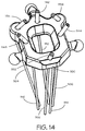
- FIG. 14 shows another embodiment of the gimbal plate.
- FIG. 1 is a simplified diagrammatic perspective view of a teleoperated surgical system 100 .
- the system 100 includes a support assembly 110 mounted to or near an operating table supporting a patient's body 122 .
- the support assembly 110 supports one or more surgical instruments 120 that operate on a surgical site within the patient's body 122 .
- instrument is used herein to describe a device configured to be inserted into a patient's body and used to carry out surgical procedures.
- the instrument includes a surgical tool, such as a forceps, a needle driver, a shears, a monopolar cauterizer, a bipolar cauterizer, a tissue stabilizer or retractor, a clip applier, an anastomosis device, an imaging device (e.g., an endoscope or ultrasound probe), and the like.
- a surgical tool such as a forceps, a needle driver, a shears, a monopolar cauterizer, a bipolar cauterizer, a tissue stabilizer or retractor, a clip applier, an anastomosis device, an imaging device (e.g., an endoscope or ultrasound probe), and the like.
- gimbal is used herein to describe a device configured to provide a motion that is constrained to provide only rotation about two orthogonal axes.
- Such devices employ a Cardan suspension in which an innermost gimbal plate is supported by a rotational axis in an inner ring that is supported in turn by an orthogonal rotational axis in an outer ring.
- the gimbal plate is constrained so that it only moves rotationally about the center of motion at the point of intersection of the two rotational axes.
- there is no net movement of any set of points that are equally spaced from the center of motion For example, the sum of changes in position of three points that are spaced 120° apart on a circle centered on the center of motion will be zero for all positions of the gimbal plate.
- a functional teleoperated surgical system would further include a vision system that enables the operator to view the surgical site from outside the patient's body 122 .
- the vision system can include a video monitor for displaying images received by an optical device provided at a distal end of one of the surgical instruments 120 .
- the optical device can include a lens coupled to an optical fiber which carries the detected images to an imaging sensor (e.g., a CCD or CMOS sensor) outside of the patient's body 122 .
- the imaging sensor may be provided at the distal end of the surgical instrument 120 , and the signals produced by the sensor are transmitted along a lead or wirelessly for display on the monitor.
- An illustrative monitor is the stereoscopic display on the surgeon's cart in the da Vinci® Surgical System, marketed by Intuitive Surgical, Inc., of Sunnyvale Calif.
- a functional teleoperated surgical system would further include a control system for controlling the insertion and articulation of the surgical instruments 120 .
- This control may be effectuated in a variety of ways, depending on the degree of control desired, the size of the surgical assembly, and other factors.
- the control system includes one or more manually operated input devices, such as a joystick, exoskeletal glove, or the like. These input devices control motors, such as servo motors, which, in turn, control the articulation of the surgical assembly.
- the forces generated by the motors are transferred via drivetrain mechanisms, which transmit the forces from the motors generated outside the patient's body 122 through an intermediate portion of the elongate surgical instrument 120 to a portion of the surgical instrument inside the patient's body 122 distal from the motor.
- drivetrain mechanisms which transmit the forces from the motors generated outside the patient's body 122 through an intermediate portion of the elongate surgical instrument 120 to a portion of the surgical instrument inside the patient's body 122 distal from the motor.
- the surgical instrument 120 is shown inserted through an entry guide 124 , e.g., a cannula in the patient's abdomen.
- a functional teleoperated surgical system may provide an entry guide manipulator (not shown; in one illustrative aspect the entry guide manipulator is part of the support system 110 ) and an instrument manipulator (discussed below).
- the entry guide 124 is mounted onto the entry guide manipulator, which includes a mechanically actuated positioning system for positioning the distal end of the entry guide 124 at the desired target surgical site.
- the mechanically actuated positioning system may be provided in a variety of forms, such as a serial link arm having multiple degrees of freedom (e.g., six degrees of freedom) or a jointed arm that provides a remote center of motion (due to either hardware or software constraints) and which is positioned by one or more unpowered, lockable setup joints mounted onto a base.
- the entry guide manipulator may be manually maneuvered so as to position the entry guide 124 in the desired location.
- the input devices that control the manipulator(s) may be provided at a location remote from the patient (outside the room in which the patient is placed). The input signals from the input devices are then transmitted to the control system, which, in turn, manipulates the manipulators 130 in response to those signals.
- the instrument manipulator may be coupled to the entry guide manipulator such that the instrument manipulator 130 moves in conjunction with the entry guide 124 .
- the surgical instrument 120 is detachably connected to the mechanically actuated instrument manipulator 130 .
- the mechanically actuated manipulator includes a coupler 132 to transfer controller motion from the mechanically actuated manipulator to the surgical instrument 120 .
- the instrument manipulator 130 may provide a number of controller motions which the surgical instrument 120 may translate into a variety of movements of the end effector on the surgical instrument such that the input provided by a surgeon through the control system is translated into a corresponding action by the surgical instrument.
- FIG. 2 is a plan view of an illustrative embodiment of the surgical instrument 120 , comprising a distal portion 250 and a proximal control mechanism 240 coupled by an elongate tube 210 .
- the distal portion 250 of the surgical instrument 120 may provide any of a variety of surgical devices such as the forceps 258 shown, a needle driver, a cautery device, a cutting tool, an imaging device (e.g., an endoscope or ultrasound probe), or a combined device that includes a combination of two or more various tools and imaging devices.
- the surgical tool 258 is coupled to the elongate tube 210 by an articulated section in the form of a “wrist” 254 that allows the orientation of the surgical tool to be manipulated.
- Surgical instruments that are used with the invention are controlled by a plurality of flexible cables. Cables provide a means of transmitting forces to the joints that is compact and flexible.
- a typical elongate tube 210 for a surgical instrument 120 is small, perhaps six millimeters in diameter, roughly the diameter of a large soda straw.
- the diminutive scale of the mechanisms in the surgical instrument 120 creates unique mechanical conditions and issues with the construction of these mechanisms that are unlike those found in similar mechanisms constructed at a larger scale because forces and strengths of materials do not scale at the same rate as the size of the mechanisms.
- the cables must fit within the elongate tube 210 and be able to bend as they pass through the joints of the “wrist” 254 .
- FIGS. 3A and 3B are two perspective views showing a wrist assembly 254 and a linkage mechanism for moving the wrist assembly that could be used with the invention with the wrist assembly shown in two operative positions.
- the linkage mechanism transfers the forces applied on an input gimbal plate 300 in a proximal control mechanism to the articulated section 254 at the distal end of the elongate tube (not shown).
- the articulated section 254 is a “wrist” that supports a surgical tool (not shown).
- the wrist 254 is coupled to the distal end of the elongate tube, which allows the wrist to be positioned adjacent the surgical site.
- the articulated section 254 in the embodiment shown includes five segments 320 , 322 , 324 , 326 , 328 that form a gimbal mechanism having two degrees of angular freedom.
- Each pair of adjacent segments e.g. 320 , 322
- the two segments of the pair can rotate (e.g., pitch or yaw) relative to one other approximately around a single axis.
- each of the two segments may rotate about its own axis that is parallel to and slightly spaced apart from the axis of rotation for the other of the two segments.
- the two segments in each of the pairs of segments are not rotating relative to each other about a single axis but rather a pair of axes to provide a “cable balancing pivotal mechanism” as described in U.S. Pat. No. 7,736,356, FIG. 25, which is hereby incorporated in its entirety by reference.
- Three adjacent segments act as a gimbal plate because the two axes of the two pairs of segments are orthogonal to one another.
- the three segments 324 , 326 , 328 farthest from the distal end of the elongate tube act as an output gimbal plate.
- the first 324 of those three segments along with the two segments 322 , 320 closest to the distal end act as a secondary output gimbal plate.
- the wrist assembly has two degrees of rotational freedom.
- the use of two stacked gimbals permits a greater range of angular movement and provides a greater radius of curvature for the articulation of the wrist.
- the stacked gimbals also allow singularity free motion in a manner similar to a double U-joint structure.
- a single U-joint contains single pair of orthogonal gimbal axes that intersect at a point. The single U-joint suffers from gimbal lock at 90 degree articulation, a condition in which the output can no longer roll.
- the secondary output gimbal plate moves to a first angle that is a portion of the total angle of the wrist movement and the output gimbal plate moves the remainder of the total angle. In the embodiment shown, the secondary output gimbal plate moves through one-half of the total angle and the output gimbal plate moves through the same amount relative to the secondary output gimbal plate to provide the total angle of movement.
- Three output linkages 302 , 304 , 306 are coupled to the most distal segment 328 of the articulated section 254 at a first end 332 of the output linkages and coupled to the input gimbal plate 300 at a second end 352 , 354 , 356 of the output linkages.
- the three output linkages are coupled to the segment and to the gimbal plate with the three ends spaced apart so that they determine the position of a plane.
- the input gimbal plate 300 moves in response to movements of force inputs as described in detail below.
- Each of three secondary output linkages 312 , 316 , 314 has a first end 336 coupled to the middle segment 324 of the articulated section 254 , which is the most distal of the three segments 320 , 322 , 324 that act as a secondary output gimbal plate, and a second end 342 , 344 , 346 coupled to input gimbal plate 300 .
- the three secondary output linkages are coupled to the segment and to the gimbal plate with the three ends spaced apart so that they determine the position of a plane.
- Each secondary output linkage is coupled to the input gimbal plate 300 at a point that is diametrically opposite the point where an associated output linkage is coupled to the input gimbal plate and at half the radius of the associated output linkage.
- the secondary output linkage designated by reference numeral 312 is associated with the output linkage designated by reference numeral 302 .
- the secondary output linkages 312 , 316 , 314 are coupled to the input gimbal plate 300 to move the secondary output linkages with a motion that is proportional to the motion of the associated output linkages 302 , 304 , 306 .
- each secondary output linkage moves one-half the distance of the associated output linkage in the opposite direction.
- the secondary output linkage is coupled to the secondary output gimbal plate 324 at a point that is diametrically opposite the point where the output linkage for the associated output linkage is coupled to the output gimbal plate 328 . This causes the secondary output gimbal plate 324 to move through half the angle of the output gimbal plate 328 . Both output gimbals move in the same direction because the diametrically opposed attachments cancel the effect of the opposite directions of motion at the input gimbal plate 300 .
- FIG. 4 is a perspective view of a mechanism for moving the input gimbal plate 10 .
- Three levers 12 , 14 , 16 are provided to support the input gimbal plate 10 .
- Each lever is rotatably supported by a fulcrum 18 .
- the fulcrums are supported by a frame 20 .
- FIGS. 5 and 6 are perspective view of the mechanism shown in FIG. 4 for moving the input gimbal plate 10 with parts removed to allow certain aspects of the mechanism to be better seen. It will be appreciated that the distance between the ends of the levers changes as the levers are moved. The distance between the points on the gimbal plate 10 that are supported on the ends of the levers are fixed. Therefore it is necessary to provide a means to accommodate the fixed spacing of the support points on the gimbal plate 10 .
- two of the levers 12 , 14 have half-cylinder surfaces 24 at the end of the levers to receive the support points of the gimbal plate 10 .
- the axes of the half-cylinder surfaces 24 is parallel to the axes of the fulcrums 18 . This maintains the support points of the gimbal plate 10 at a constant distance from the fulcrum 18 of the levers 12 , 14 while allowing the support points to move along the axes of the half-cylinder surfaces 24 to accommodate the changing distance between the ends of the levers.
- the third lever 16 drives a parallelogram linkage 22 which is further explained in the description of the second embodiment below.
- FIG. 7 is a perspective view of another mechanism for moving the input gimbal plate 300 .
- Three levers 412 , 414 , 416 are provided to support the input gimbal plate 300 .
- FIG. 8 is a perspective view of the input gimbal plate 300 .
- the input gimbal plate 300 provides three support points 402 , 404 , 506 . Each support point may be the center of a partial sphere. Each support point is supported by one of the three levers 412 , 414 , 416 .
- a first lever 416 supports a first one of the three support points 506 of the input gimbal plate 300 .
- a second lever 412 supports a second one of the three support points 402 .
- a third lever 414 supports a third one of the three support points 404 .
- the three support points 402 , 404 , 506 are equally spaced from the center of motion of the input gimbal plate 300 . Therefore the input gimbal plate can be made to move as a gimbal plate with no displacement of the center of motion if there is no net displacement of the three support points 402 , 404 , 506 .
- two of the support points 402 , 404 are equidistant from the axes of rotation for the levers. It will be appreciated that if these two support points 402 , 404 are coupled to the levers 412 , 414 such that the support points are constrained to have no displacement relative to the levers, then the levers must have a second degree of rotational freedom because the two support points move along a curved path.
- FIGS. 9 and 10 are perspective view of a mechanism shown in FIG. 7 for moving the input gimbal plate 300 with parts removed to allow certain aspects of the mechanism to be better seen.
- Each of the second 412 and third 414 levers is supported by a fulcrum support that constrains the lever to two degrees of rotational freedom.
- the lever 412 ( FIG. 9 ) is rotatably supported by a first axle 610 that allows the lever to rotate about a first axis of rotation 620 .
- the first axle 610 is in turn rotatably supported by a second axle 612 having a second axis of rotation 622 that is orthogonal to the first axis of rotation 620 .
- the second axle 612 is the fulcrum for the lever.
- the first axle 610 allows the lever to follow the curved path of motion of the two support points 402 , 404 of the input gimbal plate 300 .
- the two outside levers 412 , 414 are coupled by a spring 600 that provides an inward biasing force and draws the levers toward one another.
- the two outside levers 412 , 414 provide receptacles 602 , 604 that receive the two corresponding support points 402 , 404 .
- the receptacles 602 , 604 are constructed so that the inward biasing force of the spring 600 couples the levers 412 , 414 to the support points 402 , 404 to provide only two degrees of rotational freedom for the support points and constrain the support points to have no displacement relative to the levers.
- a stop 422 , 424 is provided on each of the second and third levers 412 , 414 that bears against the second and third support points 402 , 404 of the input gimbal plate 300 to limit movement of the levers toward one another.
- FIG. 11 is a perspective view of another lever 814 that can be used in embodiments of the invention.
- This lever 814 provides a shaped receptacle 804 for a support point 404 of the input gimbal plate 300 .
- the receptacle 804 is shaped so that the support point 404 of the input gimbal plate 300 can be engaged with or disengaged from the shaped receptacle 804 from the top of the lever 814 .
- the tension in the linkages attached to the input gimbal plate 300 hold the support point 404 of the gimbal plate in contact with the shaped receptacle 804 .
- neither the spring nor the stops are required to prevent displacement of the support points relative to the levers.
- Providing the shaped receptacle in the second and third levers is sufficient to cause the levers to follow a curved path of motion of the second and third support points of the input gimbal plate.
- FIGS. 12A and 12B are schematic elevations of a first lever 900 that supports the first one of the three support points 506 of the input gimbal plate 300 . These figures illustrate an issue that arises if a simple coupling is used between the lever 900 and the support point 506 .
- the lever 900 When the lever 900 is in a first position illustrated in FIG. 12A , the lever is coupled to the support point 506 at a first distance from the fulcrum 902 as indicated by reference numeral 904 .
- the lever 900 rotates to a second position illustrated in FIG.
- the gimbal plate 300 rotates about an axis that passes through the centers of the two other support points 402 , 404 because of the constrained coupling of these support points to the second and third levers 412 , 414 described above.
- the first lever 900 is coupled to the support point 506 at a second distance from the fulcrum 902 as indicated by reference numeral 906 . This change in distance from the fulcrum 902 causes the support point 506 not to incorrectly track the displacements applied to the first lever 900 .
- FIGS. 13A, 13B, and 13C are elevations of a coupling between the first lever 416 that supports the first one of the three support points 506 of the input gimbal plate 300 that may be used to mitigate the issue of a changing distance from the fulcrum 418 .
- a four-bar parallelogram linkage is formed with pivot points identified by reference numerals 418 , 1016 , 1006 , and 1008 .
- the portion of the first lever 416 between the lever's fulcrum 418 and the output 1016 forms the crank link of the four-bar linkage.
- the lever's fulcrum 418 and one of the pivot points 1008 are supported by the frame of the force transmission to form the fixed link of the four-bar linkage.
- a connecting rod 1000 is rotatably coupled to the fixed link at the pivot point 1008 opposite the pivot point that couples the crank link to the fixed link.
- a rocker link 700 is rotatably coupled to the crank link and the connecting rod 1000 .
- the rocker link 700 provides a flat surface 702 that couples the first one of the three support points 506 of the input gimbal plate 300 to the first lever 416 .
- the rocker link 700 is shown with a front portion cut away to allow the flat surface 702 to be seen.
- the parallelogram linkage causes the rocker link 700 to remain parallel to the fixed link. Therefore the displacement of the first lever 416 is transferred to the first one of the three support points 506 of the input gimbal plate 300 without the issues of changing distances from the lever's fulcrum point 418 .
- the second ends 352 , 354 , 356 of the output linkages 302 , 304 , 306 and the second ends 342 , 344 , 346 of the secondary output linkages 312 , 316 , 314 may include a termination that provides a spherical surface that is supported by a corresponding recess in the input gimbal plate 300 . This may allow the second ends of the output linkages to swivel in the input gimbal plate.
- FIG. 14 shows another embodiment in which the second ends 1152 , 1154 , 1156 of the output linkages 1102 , 1104 , 1106 and the second ends 1142 , 1144 , 1146 of the secondary output linkages 1112 , 1116 , 1114 may include a terminations that are received in recesses in the input gimbal plate 1100 that do not allow the terminations to move in response to movements of the input gimbal plate.
- the output linkages may be formed of a flexible material, such as a stranded cable, that provides the necessary compliance at the second ends of the output linkages.
Landscapes
- Engineering & Computer Science (AREA)
- Health & Medical Sciences (AREA)
- Life Sciences & Earth Sciences (AREA)
- Surgery (AREA)
- Robotics (AREA)
- Molecular Biology (AREA)
- Veterinary Medicine (AREA)
- Biomedical Technology (AREA)
- Heart & Thoracic Surgery (AREA)
- Medical Informatics (AREA)
- Nuclear Medicine, Radiotherapy & Molecular Imaging (AREA)
- Animal Behavior & Ethology (AREA)
- General Health & Medical Sciences (AREA)
- Public Health (AREA)
- Mechanical Engineering (AREA)
- Physics & Mathematics (AREA)
- Biophysics (AREA)
- Optics & Photonics (AREA)
- Pathology (AREA)
- Radiology & Medical Imaging (AREA)
- General Engineering & Computer Science (AREA)
- Manipulator (AREA)
Abstract
Description
Claims (27)
Priority Applications (4)
| Application Number | Priority Date | Filing Date | Title |
|---|---|---|---|
| US14/461,320 US10550918B2 (en) | 2013-08-15 | 2014-08-15 | Lever actuated gimbal plate |
| US16/780,432 US11248686B2 (en) | 2013-08-15 | 2020-02-03 | Lever actuated gimbal plate |
| US17/569,378 US11624428B2 (en) | 2013-08-15 | 2022-01-05 | Lever actuated gimbal plate |
| US18/113,775 US11969889B2 (en) | 2013-08-15 | 2023-02-24 | Lever actuated gimbal plate |
Applications Claiming Priority (2)
| Application Number | Priority Date | Filing Date | Title |
|---|---|---|---|
| US201361866238P | 2013-08-15 | 2013-08-15 | |
| US14/461,320 US10550918B2 (en) | 2013-08-15 | 2014-08-15 | Lever actuated gimbal plate |
Related Child Applications (1)
| Application Number | Title | Priority Date | Filing Date |
|---|---|---|---|
| US16/780,432 Continuation US11248686B2 (en) | 2013-08-15 | 2020-02-03 | Lever actuated gimbal plate |
Publications (2)
| Publication Number | Publication Date |
|---|---|
| US20150047454A1 US20150047454A1 (en) | 2015-02-19 |
| US10550918B2 true US10550918B2 (en) | 2020-02-04 |
Family
ID=52465854
Family Applications (4)
| Application Number | Title | Priority Date | Filing Date |
|---|---|---|---|
| US14/461,320 Active 2038-12-06 US10550918B2 (en) | 2013-08-15 | 2014-08-15 | Lever actuated gimbal plate |
| US16/780,432 Active 2034-11-18 US11248686B2 (en) | 2013-08-15 | 2020-02-03 | Lever actuated gimbal plate |
| US17/569,378 Active US11624428B2 (en) | 2013-08-15 | 2022-01-05 | Lever actuated gimbal plate |
| US18/113,775 Active US11969889B2 (en) | 2013-08-15 | 2023-02-24 | Lever actuated gimbal plate |
Family Applications After (3)
| Application Number | Title | Priority Date | Filing Date |
|---|---|---|---|
| US16/780,432 Active 2034-11-18 US11248686B2 (en) | 2013-08-15 | 2020-02-03 | Lever actuated gimbal plate |
| US17/569,378 Active US11624428B2 (en) | 2013-08-15 | 2022-01-05 | Lever actuated gimbal plate |
| US18/113,775 Active US11969889B2 (en) | 2013-08-15 | 2023-02-24 | Lever actuated gimbal plate |
Country Status (1)
| Country | Link |
|---|---|
| US (4) | US10550918B2 (en) |
Cited By (8)
| Publication number | Priority date | Publication date | Assignee | Title |
|---|---|---|---|---|
| US11026759B2 (en) | 2017-02-24 | 2021-06-08 | Intuitive Surgical Operations, Inc. | Splayed cable guide for a medical instrument |
| US11207145B2 (en) | 2016-07-14 | 2021-12-28 | Intuitive Surgical Operations, Inc. | Multi-cable medical instrument |
| US11241290B2 (en) | 2016-11-21 | 2022-02-08 | Intuitive Surgical Operations, Inc. | Cable length conserving medical instrument |
| US11248686B2 (en) | 2013-08-15 | 2022-02-15 | Intuitive Surgical Operations, Inc. | Lever actuated gimbal plate |
| US11357526B2 (en) | 2011-05-13 | 2022-06-14 | Intuitive Surgical Operations, Inc. | Medical instrument with snake wrist structure |
| US12239394B2 (en) | 2019-06-13 | 2025-03-04 | Intuitive Surgical Operations, Inc. | Medical tool with length conservation mechanism for actuating tension bands |
| US12390291B2 (en) | 2018-11-15 | 2025-08-19 | Intuitive Surgical Operations, Inc. | Decoupling tool shaft from cable drive load |
| US12544171B2 (en) | 2021-04-29 | 2026-02-10 | Intuitive Surgical Operations, Inc. | Medical instrument having single input for driving multiple cables |
Families Citing this family (34)
| Publication number | Priority date | Publication date | Assignee | Title |
|---|---|---|---|---|
| US9204923B2 (en) | 2008-07-16 | 2015-12-08 | Intuitive Surgical Operations, Inc. | Medical instrument electronically energized using drive cables |
| US12402960B2 (en) | 2010-10-11 | 2025-09-02 | Ecole Polytechnique Federale De Lausanne (Epfl) | Mechanical manipulator for surgical instruments |
| US10076348B2 (en) | 2013-08-15 | 2018-09-18 | Intuitive Surgical Operations, Inc. | Rotary input for lever actuation |
| JP6220085B2 (en) | 2014-02-03 | 2017-10-25 | ディスタルモーション エスエーDistalmotion Sa | Mechanical remote control device with replaceable distal device |
| WO2016187056A1 (en) * | 2015-05-15 | 2016-11-24 | The Johns Hopkins University | Manipulator device and therapeutic and diagnostic methods |
| JP6110527B1 (en) * | 2016-01-28 | 2017-04-05 | 上銀科技股▲分▼有限公司 | Control mechanism for elastic medical devices |
| CN113995532B (en) | 2016-07-14 | 2024-11-01 | 直观外科手术操作公司 | Instrument irrigation system |
| US11076926B2 (en) | 2017-03-21 | 2021-08-03 | Intuitive Surgical Operations, Inc. | Manual release for medical device drive system |
| US11058503B2 (en) | 2017-05-11 | 2021-07-13 | Distalmotion Sa | Translational instrument interface for surgical robot and surgical robot systems comprising the same |
| KR102332121B1 (en) | 2017-12-14 | 2021-12-01 | 인튜어티브 서지컬 오퍼레이션즈 인코포레이티드 | medical instrument with tension band |
| US12376927B2 (en) | 2018-02-07 | 2025-08-05 | Distalmotion Sa | Surgical robot systems comprising robotic telemanipulators and integrated laparoscopy |
| AU2019218707B2 (en) | 2018-02-07 | 2024-10-24 | Distalmotion Sa | Surgical robot systems comprising robotic telemanipulators and integrated laparoscopy |
| US11497567B2 (en) * | 2018-02-08 | 2022-11-15 | Intuitive Surgical Operations, Inc. | Jointed control platform |
| US11118661B2 (en) | 2018-02-12 | 2021-09-14 | Intuitive Surgical Operations, Inc. | Instrument transmission converting roll to linear actuation |
| WO2019173268A1 (en) | 2018-03-07 | 2019-09-12 | Intuitive Surgical Operations, Inc. | Low-friction, small profile medical tools having easy-to-assemble components |
| EP3761897A4 (en) | 2018-03-07 | 2021-11-24 | Intuitive Surgical Operations, Inc. | LOW-FRICTION, LOW-PRESSURE MEDICAL TOOLS WITH EASY-TO-ASSEMBLE COMPONENTS |
| WO2020102780A1 (en) | 2018-11-15 | 2020-05-22 | Intuitive Surgical Operations, Inc. | Cable drive limited slip capstan and shaft |
| US12188838B2 (en) | 2019-09-17 | 2025-01-07 | Intuitive Surgical Operations, Inc. | Compact, differential, coaxial inductive force sensor |
| CN115768372A (en) | 2020-05-18 | 2023-03-07 | 直观外科手术操作公司 | Apparatus and method for stress/strain isolation on a force sensor unit |
| DE112021004800T5 (en) | 2020-09-14 | 2023-07-27 | Intuitive Surgical Operations, Inc. | Devices and methods for a compact, redundant inductive force sensor |
| EP4221605B1 (en) | 2020-10-02 | 2026-01-28 | Intuitive Surgical Operations, Inc. | Medical devices having compact end effector drive mechanisms with high grip force |
| CN116669650A (en) | 2020-12-17 | 2023-08-29 | 直观外科手术操作公司 | Apparatus and method with force sensing unit for axis translation and roll |
| WO2023177565A1 (en) | 2022-03-15 | 2023-09-21 | Intuitive Surgical Operations, Inc. | Medical device wrist |
| CN120187379A (en) | 2022-11-15 | 2025-06-20 | 直观外科手术操作公司 | Force Sensing Medical Devices |
| EP4620010A1 (en) | 2022-11-15 | 2025-09-24 | Intuitive Surgical Operations, Inc. | Force sensing medical instrument |
| WO2024155812A1 (en) | 2023-01-20 | 2024-07-25 | Intuitive Surgical Operations, Inc. | Systems and methods for control of a surgical system |
| WO2024215716A1 (en) | 2023-04-11 | 2024-10-17 | Intuitive Surgical Operations, Inc. | Surgical stapling instruments and control systems for such instruments |
| WO2024220525A1 (en) | 2023-04-19 | 2024-10-24 | Intuitive Surgical Operations, Inc. | Medical instrument wrist with cable routing |
| WO2025049464A1 (en) | 2023-08-29 | 2025-03-06 | Intuitive Surgical Operations, Inc. | Systems and methods for control of a surgical system |
| CN120857913A (en) | 2023-08-29 | 2025-10-28 | 直观外科手术操作公司 | Systems and methods for controlling a surgical system |
| WO2025085388A1 (en) | 2023-10-16 | 2025-04-24 | Intuitive Surgical Operations, Inc. | Rotary to linear force articulation members for surgical instruments |
| WO2025085389A1 (en) | 2023-10-16 | 2025-04-24 | Intuitive Surgical Operations, Inc. | Miniature capstan actuators for surgical instruments |
| WO2025128495A1 (en) | 2023-12-11 | 2025-06-19 | Intuitive Surgical Operations, Inc. | Focal therapy medical devices and methods for deep-seated targets |
| CN119217350B (en) * | 2024-09-30 | 2025-10-10 | 大连理工大学 | An underactuated core-column continuum robot for tasks in narrow spaces |
Citations (9)
| Publication number | Priority date | Publication date | Assignee | Title |
|---|---|---|---|---|
| US2421279A (en) | 1943-03-25 | 1947-05-27 | Emanuel Merian | Body with movable parts |
| US5317952A (en) * | 1991-11-22 | 1994-06-07 | Kinetic Sciences Inc. | Tentacle-like manipulators with adjustable tension lines |
| US6322312B1 (en) * | 1999-03-18 | 2001-11-27 | Applied Materials, Inc. | Mechanical gripper for wafer handling robots |
| US6817974B2 (en) | 2001-06-29 | 2004-11-16 | Intuitive Surgical, Inc. | Surgical tool having positively positionable tendon-actuated multi-disk wrist joint |
| US20110277580A1 (en) * | 2010-05-14 | 2011-11-17 | Intuitive Surgical Operations, Inc. | Force Transmission for Robotic Surgical Instrument |
| US8316961B2 (en) * | 2009-05-08 | 2012-11-27 | Ntn Corporation | Remote-controlled work robot |
| US8808166B2 (en) * | 2006-06-06 | 2014-08-19 | Olympus Corporation | Endoscope |
| US9243696B2 (en) * | 2011-09-22 | 2016-01-26 | Ntn Corporation | Link actuating device |
| US20160361123A1 (en) * | 2014-03-07 | 2016-12-15 | Cambridge Medical Robotics Limited | Surgical arm |
Family Cites Families (149)
| Publication number | Priority date | Publication date | Assignee | Title |
|---|---|---|---|---|
| US2906143A (en) | 1955-03-21 | 1959-09-29 | United Shoe Machinery Corp | Strain wave gearing |
| US3312496A (en) | 1965-09-14 | 1967-04-04 | Boutelle Albert | Underwater manipulator |
| US3618420A (en) | 1970-01-07 | 1971-11-09 | Casco Products Corp | Mechanical remote control apparatus |
| US4139104A (en) | 1975-07-25 | 1979-02-13 | George Mink | Material handling apparatus |
| JPS54140358A (en) | 1978-04-04 | 1979-10-31 | Lansing Bagnall Ltd | Holding mechanism |
| US4540211A (en) | 1983-02-02 | 1985-09-10 | Android Corporation | Jaw assembly |
| US4751821A (en) * | 1985-03-29 | 1988-06-21 | Birchard William G | Digital linear actuator |
| US4705311A (en) | 1986-02-27 | 1987-11-10 | Universal Instruments Corporation | Component pick and place spindle assembly with compact internal linear and rotary displacement motors and interchangeable tool assemblies |
| US4728137A (en) | 1986-07-22 | 1988-03-01 | American Engineering And Trade, Inc. | Compound toggle robotic gripper |
| US5099705A (en) | 1989-12-05 | 1992-03-31 | Konstantins Dravnieks | Hand-held reciprocating working tool |
| US5207691A (en) | 1991-11-01 | 1993-05-04 | Medical Scientific, Inc. | Electrosurgical clip applicator |
| US5325845A (en) | 1992-06-08 | 1994-07-05 | Adair Edwin Lloyd | Steerable sheath for use with selected removable optical catheter |
| JPH06114000A (en) | 1992-09-30 | 1994-04-26 | Olympus Optical Co Ltd | Medical manipulator |
| US5876325A (en) | 1993-11-02 | 1999-03-02 | Olympus Optical Co., Ltd. | Surgical manipulation system |
| US5814038A (en) | 1995-06-07 | 1998-09-29 | Sri International | Surgical manipulator for a telerobotic system |
| DE19541458C1 (en) | 1995-11-07 | 1997-03-06 | Siemens Ag | Flexible actuator e.g. for domestic appliances |
| US5855583A (en) | 1996-02-20 | 1999-01-05 | Computer Motion, Inc. | Method and apparatus for performing minimally invasive cardiac procedures |
| US5792135A (en) | 1996-05-20 | 1998-08-11 | Intuitive Surgical, Inc. | Articulated surgical instrument for performing minimally invasive surgery with enhanced dexterity and sensitivity |
| US5807377A (en) | 1996-05-20 | 1998-09-15 | Intuitive Surgical, Inc. | Force-reflecting surgical instrument and positioning mechanism for performing minimally invasive surgery with enhanced dexterity and sensitivity |
| US8206406B2 (en) | 1996-12-12 | 2012-06-26 | Intuitive Surgical Operations, Inc. | Disposable sterile surgical adaptor |
| US6331181B1 (en) | 1998-12-08 | 2001-12-18 | Intuitive Surgical, Inc. | Surgical robotic tools, data architecture, and use |
| JP3578375B2 (en) | 1997-03-17 | 2004-10-20 | 技術研究組合医療福祉機器研究所 | Robot arm drive and robot hand |
| US7169141B2 (en) | 1998-02-24 | 2007-01-30 | Hansen Medical, Inc. | Surgical instrument |
| US7090683B2 (en) | 1998-02-24 | 2006-08-15 | Hansen Medical, Inc. | Flexible instrument |
| US20020095175A1 (en) | 1998-02-24 | 2002-07-18 | Brock David L. | Flexible instrument |
| JP4542710B2 (en) | 1998-11-23 | 2010-09-15 | マイクロデクステラティー・システムズ・インコーポレーテッド | Surgical manipulator |
| US6394998B1 (en) | 1999-01-22 | 2002-05-28 | Intuitive Surgical, Inc. | Surgical tools for use in minimally invasive telesurgical applications |
| US20030135204A1 (en) | 2001-02-15 | 2003-07-17 | Endo Via Medical, Inc. | Robotically controlled medical instrument with a flexible section |
| US6994708B2 (en) | 2001-04-19 | 2006-02-07 | Intuitive Surgical | Robotic tool with monopolar electro-surgical scissors |
| JP2003024336A (en) | 2001-07-16 | 2003-01-28 | Hitachi Ltd | Operation instrument |
| AT413420B (en) | 2002-06-07 | 2006-02-15 | Techmo Entw & Vertriebs Gmbh | METHOD AND ARRANGEMENT FOR BREAKING CONNECTING AND RELEASING COMPOUND ELEMENTS |
| US7331967B2 (en) | 2002-09-09 | 2008-02-19 | Hansen Medical, Inc. | Surgical instrument coupling mechanism |
| JP3944108B2 (en) | 2003-03-31 | 2007-07-11 | 株式会社東芝 | Power transmission mechanism and manipulator for medical manipulator |
| US8118732B2 (en) | 2003-04-01 | 2012-02-21 | Boston Scientific Scimed, Inc. | Force feedback control system for video endoscope |
| WO2005009482A2 (en) | 2003-05-21 | 2005-02-03 | The Johns Hopkins University | Devices, systems and methods for minimally invasive surgery of the throat and other portions of mammalian body |
| US9002518B2 (en) | 2003-06-30 | 2015-04-07 | Intuitive Surgical Operations, Inc. | Maximum torque driving of robotic surgical tools in robotic surgical systems |
| US7338513B2 (en) | 2003-10-30 | 2008-03-04 | Cambridge Endoscopic Devices, Inc. | Surgical instrument |
| ITPI20030107A1 (en) | 2003-11-14 | 2005-05-15 | Massimo Bergamasco | DEVICE FOR PERFORMING OPERATIONS |
| US8052636B2 (en) | 2004-03-05 | 2011-11-08 | Hansen Medical, Inc. | Robotic catheter system and methods |
| JP2005288590A (en) | 2004-03-31 | 2005-10-20 | Hiroshi Kinoshita | Multi-joint manipulator |
| US9072535B2 (en) | 2011-05-27 | 2015-07-07 | Ethicon Endo-Surgery, Inc. | Surgical stapling instruments with rotatable staple deployment arrangements |
| US8800838B2 (en) | 2005-08-31 | 2014-08-12 | Ethicon Endo-Surgery, Inc. | Robotically-controlled cable-based surgical end effectors |
| US9289112B2 (en) | 2006-01-13 | 2016-03-22 | Olympus Corporation | Medical treatment endoscope having an operation stick formed to allow a procedure instrument to pass |
| EP1815950A1 (en) | 2006-02-03 | 2007-08-08 | The European Atomic Energy Community (EURATOM), represented by the European Commission | Robotic surgical system for performing minimally invasive medical procedures |
| US20070232858A1 (en) | 2006-03-31 | 2007-10-04 | Boston Scientific Scimed, Inc. | Steering system tension control devices |
| KR101477125B1 (en) | 2006-06-13 | 2014-12-29 | 인튜어티브 서지컬 인코포레이티드 | Minimally invasive surgical system |
| US8597280B2 (en) | 2006-06-13 | 2013-12-03 | Intuitive Surgical Operations, Inc. | Surgical instrument actuator |
| US8551076B2 (en) * | 2006-06-13 | 2013-10-08 | Intuitive Surgical Operations, Inc. | Retrograde instrument |
| US7736254B2 (en) | 2006-10-12 | 2010-06-15 | Intuitive Surgical Operations, Inc. | Compact cable tension tender device |
| US8157793B2 (en) | 2006-10-25 | 2012-04-17 | Terumo Kabushiki Kaisha | Manipulator for medical use |
| US7935130B2 (en) | 2006-11-16 | 2011-05-03 | Intuitive Surgical Operations, Inc. | Two-piece end-effectors for robotic surgical tools |
| US8715270B2 (en) | 2006-12-01 | 2014-05-06 | Boston Scientific Scimed, Inc. | Multi-part instrument systems and methods |
| US8684253B2 (en) | 2007-01-10 | 2014-04-01 | Ethicon Endo-Surgery, Inc. | Surgical instrument with wireless communication between a control unit of a robotic system and remote sensor |
| EP4233962B1 (en) | 2007-05-18 | 2025-11-05 | Boston Scientific Scimed, Inc. | Medical drive systems |
| US9096033B2 (en) | 2007-06-13 | 2015-08-04 | Intuitive Surgical Operations, Inc. | Surgical system instrument sterile adapter |
| US8444631B2 (en) | 2007-06-14 | 2013-05-21 | Macdonald Dettwiler & Associates Inc | Surgical manipulator |
| EP2197363B1 (en) | 2007-09-21 | 2016-11-02 | Covidien LP | Surgical device |
| US8224484B2 (en) | 2007-09-30 | 2012-07-17 | Intuitive Surgical Operations, Inc. | Methods of user interface with alternate tool mode for robotic surgical tools |
| US20090198272A1 (en) | 2008-02-06 | 2009-08-06 | Lawrence Kerver | Method and apparatus for articulating the wrist of a laparoscopic grasping instrument |
| US8573465B2 (en) | 2008-02-14 | 2013-11-05 | Ethicon Endo-Surgery, Inc. | Robotically-controlled surgical end effector system with rotary actuated closure systems |
| US9179912B2 (en) | 2008-02-14 | 2015-11-10 | Ethicon Endo-Surgery, Inc. | Robotically-controlled motorized surgical cutting and fastening instrument |
| KR100975047B1 (en) | 2008-02-15 | 2010-08-11 | (주)미래컴퍼니 | Coupling Structure of Surgical Instruments |
| US8945096B2 (en) * | 2008-06-05 | 2015-02-03 | Carnegie Mellon University | Extendable articulated probe device |
| CN102014759B (en) | 2008-06-11 | 2012-12-26 | 韩商未来股份有限公司 | Instrument of surgical robot arm |
| US20140100558A1 (en) | 2012-10-05 | 2014-04-10 | Gregory P. Schmitz | Micro-articulated surgical instruments using micro gear actuation |
| US8771270B2 (en) | 2008-07-16 | 2014-07-08 | Intuitive Surgical Operations, Inc. | Bipolar cautery instrument |
| US9204923B2 (en) | 2008-07-16 | 2015-12-08 | Intuitive Surgical Operations, Inc. | Medical instrument electronically energized using drive cables |
| US9386983B2 (en) | 2008-09-23 | 2016-07-12 | Ethicon Endo-Surgery, Llc | Robotically-controlled motorized surgical instrument |
| US9259274B2 (en) | 2008-09-30 | 2016-02-16 | Intuitive Surgical Operations, Inc. | Passive preload and capstan drive for surgical instruments |
| US8720448B2 (en) | 2008-11-07 | 2014-05-13 | Hansen Medical, Inc. | Sterile interface apparatus |
| US8317746B2 (en) * | 2008-11-20 | 2012-11-27 | Hansen Medical, Inc. | Automated alignment |
| US8602031B2 (en) | 2009-01-12 | 2013-12-10 | Hansen Medical, Inc. | Modular interfaces and drive actuation through barrier |
| WO2010090292A2 (en) | 2009-02-03 | 2010-08-12 | Terumo Kabushiki Kaisha | Medical manipulator |
| US20110015648A1 (en) * | 2009-07-16 | 2011-01-20 | Hansen Medical, Inc. | Endoscopic robotic catheter system |
| US8551115B2 (en) | 2009-09-23 | 2013-10-08 | Intuitive Surgical Operations, Inc. | Curved cannula instrument |
| WO2011060318A1 (en) | 2009-11-13 | 2011-05-19 | Intuitive Surgical Operations, Inc. | Motor interface for parallel drive shafts within an independently rotating member |
| JP5875973B2 (en) | 2010-03-15 | 2016-03-02 | カール シュトルツ ゲゼルシャフト ミット ベシュレンクテル ハフツング ウント コンパニー コマンディートゲゼルシャフト | Medical manipulator |
| WO2011114568A1 (en) | 2010-03-17 | 2011-09-22 | オリンパスメディカルシステムズ株式会社 | Endoscope system |
| US9101379B2 (en) | 2010-11-12 | 2015-08-11 | Intuitive Surgical Operations, Inc. | Tension control in actuation of multi-joint medical instruments |
| CN103209657B (en) | 2010-11-15 | 2016-03-23 | 直观外科手术操作公司 | Decoupling Instrument Shaft Rolling and End Effector Actuation in Surgical Instruments |
| US9259277B2 (en) | 2011-05-13 | 2016-02-16 | Intuitive Surgical Operations, Inc. | Instrument actuation interface |
| WO2012166806A1 (en) | 2011-05-31 | 2012-12-06 | Intuitive Surgical Operations, Inc. | Grip force control in a robotic surgical instrument |
| US10098703B2 (en) | 2011-08-16 | 2018-10-16 | Intuitive Surgical Operations, Inc. | Surgical instrument with commonly actuated robotic and manual features |
| US9924941B2 (en) | 2011-10-26 | 2018-03-27 | Intuitive Surgical Operations, Inc. | Surgical instrument with integral knife blade |
| CN103945783B (en) | 2011-11-15 | 2016-10-26 | 直观外科手术操作公司 | Surgical instruments with retracted blades |
| US8968312B2 (en) | 2011-11-16 | 2015-03-03 | Covidien Lp | Surgical device with powered articulation wrist rotation |
| JP6475987B2 (en) | 2011-11-23 | 2019-02-27 | リブスメド インコーポレーテッド | Surgical instrument |
| US9131987B2 (en) | 2011-12-02 | 2015-09-15 | Ethicon Endo-Surgery, Inc. | Elbow assembly for surgical devices |
| WO2013108776A1 (en) | 2012-01-16 | 2013-07-25 | オリンパスメディカルシステムズ株式会社 | Insertion device |
| KR101833347B1 (en) * | 2012-02-06 | 2018-02-28 | 삼성전자주식회사 | Link unit, arm module and apparatus for surgery having the same |
| JP6165780B2 (en) | 2012-02-10 | 2017-07-19 | エシコン・エンド−サージェリィ・インコーポレイテッドEthicon Endo−Surgery,Inc. | Robot-controlled surgical instrument |
| US20140005678A1 (en) | 2012-06-28 | 2014-01-02 | Ethicon Endo-Surgery, Inc. | Rotary drive arrangements for surgical instruments |
| US20140005718A1 (en) | 2012-06-28 | 2014-01-02 | Ethicon Endo-Surgery, Inc. | Multi-functional powered surgical device with external dissection features |
| US9125662B2 (en) | 2012-06-28 | 2015-09-08 | Ethicon Endo-Surgery, Inc. | Multi-axis articulating and rotating surgical tools |
| US9028494B2 (en) | 2012-06-28 | 2015-05-12 | Ethicon Endo-Surgery, Inc. | Interchangeable end effector coupling arrangement |
| US9095367B2 (en) | 2012-10-22 | 2015-08-04 | Ethicon Endo-Surgery, Inc. | Flexible harmonic waveguides/blades for surgical instruments |
| US10201365B2 (en) | 2012-10-22 | 2019-02-12 | Ethicon Llc | Surgeon feedback sensing and display methods |
| JP6364013B2 (en) | 2012-11-02 | 2018-07-25 | インテュイティブ サージカル オペレーションズ, インコーポレイテッド | Self-conflict drive for medical devices |
| US9839481B2 (en) | 2013-03-07 | 2017-12-12 | Intuitive Surgical Operations, Inc. | Hybrid manual and robotic interventional instruments and methods of use |
| US9737300B2 (en) | 2013-03-13 | 2017-08-22 | Ethicon Llc | Electrosurgical device with disposable shaft having rack and pinion drive |
| EP3900641A1 (en) | 2013-03-14 | 2021-10-27 | SRI International Inc. | Wrist and grasper system for a robotic tool |
| US9408669B2 (en) | 2013-03-15 | 2016-08-09 | Hansen Medical, Inc. | Active drive mechanism with finite range of motion |
| JP2014191707A (en) | 2013-03-28 | 2014-10-06 | Seiko Epson Corp | Label production device and label production method |
| CN108095826B (en) | 2013-05-15 | 2021-04-30 | 直观外科手术操作公司 | Force transmission mechanism for teleoperated surgical system |
| EP3708105B1 (en) | 2013-08-15 | 2022-02-09 | Intuitive Surgical Operations, Inc. | Preloaded surgical instrument interface |
| US10932868B2 (en) | 2013-08-15 | 2021-03-02 | Intuitive Surgical Operations, Inc. | Variable instrument preload mechanism controller |
| US10550918B2 (en) | 2013-08-15 | 2020-02-04 | Intuitive Surgical Operations, Inc. | Lever actuated gimbal plate |
| US9839439B2 (en) | 2013-08-15 | 2017-12-12 | Intuitive Surgical Operations, Inc. | Rotary input lever gimbal |
| CN108784838B (en) | 2013-08-15 | 2021-06-08 | 直观外科手术操作公司 | Instrument sterile adapter drive interface |
| US9937007B2 (en) | 2013-08-15 | 2018-04-10 | Intuitive Surgical Operations, Inc. | Angled instrument shaft roll actuator |
| US10076348B2 (en) | 2013-08-15 | 2018-09-18 | Intuitive Surgical Operations, Inc. | Rotary input for lever actuation |
| US9955966B2 (en) | 2013-09-17 | 2018-05-01 | Covidien Lp | Adapter direct drive with manual retraction, lockout, and connection mechanisms for improper use prevention |
| EP3386403A1 (en) | 2013-11-22 | 2018-10-17 | Srivastava, Sudhir Prem | Motorized surgical instrument |
| CZ304972B6 (en) | 2013-12-12 | 2015-02-18 | Ing. Petr Gross S.R.O. | Laparoscopic radio frequency surgical instrument, particularly for liver resections |
| JP6210900B2 (en) | 2014-02-07 | 2017-10-11 | オリンパス株式会社 | Traction balance adjustment mechanism, manipulator and manipulator system |
| JP6153484B2 (en) | 2014-02-24 | 2017-06-28 | オリンパス株式会社 | Wire drive device and manipulator |
| EP3119316B1 (en) | 2014-03-17 | 2020-05-27 | Intuitive Surgical Operations, Inc. | Sterile drape with sterile adapter comprising mounting datum for surgical instrument |
| US20170127911A1 (en) | 2014-03-19 | 2017-05-11 | Endomaster Pte Ltd | Master - slave flexible robotic endoscopy system |
| KR102592615B1 (en) | 2014-03-31 | 2023-10-24 | 인튜어티브 서지컬 오퍼레이션즈 인코포레이티드 | Surgical instrument with shiftable transmission |
| KR102414384B1 (en) | 2014-08-12 | 2022-06-30 | 인튜어티브 서지컬 오퍼레이션즈 인코포레이티드 | Detecting uncontrolled movement |
| WO2016025700A1 (en) | 2014-08-15 | 2016-02-18 | Intuitive Surgical Operations, Inc. | Force transmission mechanism for surgical instrument, and related systems and methods |
| DE102014117408A1 (en) | 2014-11-27 | 2016-06-02 | avateramedical GmBH | Device for robotic surgery |
| US10166065B2 (en) | 2014-12-03 | 2019-01-01 | Ethicon Llc | Devices and methods for clamping and cutting tissue |
| CN107107343B (en) | 2014-12-11 | 2020-04-10 | 提坦医疗公司 | Actuator and driver for steering a tool |
| CN107073723A (en) | 2015-02-25 | 2017-08-18 | 奥林巴斯株式会社 | Manipulator and arm-and-hand system |
| WO2016161449A1 (en) | 2015-04-03 | 2016-10-06 | The Regents Of The University Of Michigan | Tension management apparatus for cable-driven transmission |
| US11185380B2 (en) | 2015-04-22 | 2021-11-30 | Intuitive Surgical Operations, Inc. | Tension regulator for actuation elements, and related remotely actuated instruments, systems, and methods |
| GB2538710B (en) | 2015-05-22 | 2020-09-23 | Cmr Surgical Ltd | Surgical robot driving mechanism |
| US9795435B2 (en) | 2015-05-22 | 2017-10-24 | Covidien Lp | Surgical instruments and methods for performing tonsillectomy, adenoidectomy, and other surgical procedures |
| CN204941289U (en) | 2015-07-24 | 2016-01-06 | 亿丰综合工业股份有限公司 | Split FM structure |
| ITUB20155057A1 (en) | 2015-10-16 | 2017-04-16 | Medical Microinstruments S R L | Robotic surgery set |
| GB201521810D0 (en) | 2015-12-10 | 2016-01-27 | Cambridge Medical Robotics Ltd | Supporting body of a surgical instrument articulation |
| US10299821B2 (en) | 2016-01-15 | 2019-05-28 | Ethicon Llc | Modular battery powered handheld surgical instrument with motor control limit profile |
| WO2017156070A1 (en) | 2016-03-09 | 2017-09-14 | Intuitive Surgical Operations, Inc. | Force transmission mechanism for surgical instrument, and related devices, systems, and methods |
| RU2636853C2 (en) | 2016-04-29 | 2017-11-28 | Общество с ограниченной ответственностью "МРОБОТИКС" (ООО "МРОБОТИКС") | End effector with hinge assembly and endoscopic surgical apparatus drive |
| WO2018013316A1 (en) | 2016-07-14 | 2018-01-18 | Intuitive Surgical Operations, Inc. | Geared roll drive for medical instrument |
| EP4413942A3 (en) | 2016-07-14 | 2024-10-30 | Intuitive Surgical Operations, Inc. | Multi-cable medical instrument |
| US11007024B2 (en) | 2016-07-14 | 2021-05-18 | Intuitive Surgical Operations, Inc. | Geared grip actuation for medical instruments |
| WO2018044306A1 (en) | 2016-08-31 | 2018-03-08 | Auris Surgical Robotics, Inc. | Length conservative surgical instrument |
| KR102780460B1 (en) | 2016-10-14 | 2025-03-14 | 인튜어티브 서지컬 오퍼레이션즈 인코포레이티드 | Systems to apply preload tension for surgical instruments and related methods |
| GB2554915B (en) | 2016-10-14 | 2022-03-02 | Cmr Surgical Ltd | Driving arrangement for articulating a surgical instrument |
| WO2018094191A1 (en) | 2016-11-21 | 2018-05-24 | Intuitive Surgical Operations, Inc. | Cable length conserving medical instrument |
| US11224733B2 (en) | 2017-02-16 | 2022-01-18 | Intuitive Surgical Operations, Inc. | Complex irrigation/suction flow path in a medical device |
| US11446104B2 (en) | 2017-10-26 | 2022-09-20 | Cilag Gmbh International | Manual release assembly for robotic surgical tool |
| US11497567B2 (en) | 2018-02-08 | 2022-11-15 | Intuitive Surgical Operations, Inc. | Jointed control platform |
| US11118661B2 (en) | 2018-02-12 | 2021-09-14 | Intuitive Surgical Operations, Inc. | Instrument transmission converting roll to linear actuation |
| WO2020102776A1 (en) | 2018-11-15 | 2020-05-22 | Intuitive Surgical Operations, Inc. | Surgical instrument with sensor aligned cable guide |
| CN113811257B (en) | 2019-06-13 | 2025-09-30 | 直观外科手术操作公司 | Medical tool with length conservation mechanism for actuating a tension band |
| US20250186147A1 (en) | 2022-03-15 | 2025-06-12 | Intuitive Surgical Operations, Inc. | Manual jaw grip release detection |
-
2014
- 2014-08-15 US US14/461,320 patent/US10550918B2/en active Active
-
2020
- 2020-02-03 US US16/780,432 patent/US11248686B2/en active Active
-
2022
- 2022-01-05 US US17/569,378 patent/US11624428B2/en active Active
-
2023
- 2023-02-24 US US18/113,775 patent/US11969889B2/en active Active
Patent Citations (10)
| Publication number | Priority date | Publication date | Assignee | Title |
|---|---|---|---|---|
| US2421279A (en) | 1943-03-25 | 1947-05-27 | Emanuel Merian | Body with movable parts |
| US5317952A (en) * | 1991-11-22 | 1994-06-07 | Kinetic Sciences Inc. | Tentacle-like manipulators with adjustable tension lines |
| US6322312B1 (en) * | 1999-03-18 | 2001-11-27 | Applied Materials, Inc. | Mechanical gripper for wafer handling robots |
| US6817974B2 (en) | 2001-06-29 | 2004-11-16 | Intuitive Surgical, Inc. | Surgical tool having positively positionable tendon-actuated multi-disk wrist joint |
| US7736356B2 (en) * | 2001-06-29 | 2010-06-15 | Intutive Surgical Operations, Inc. | Surgical tool having positively positionable tendon-actuated multi-disk wrist joint |
| US8808166B2 (en) * | 2006-06-06 | 2014-08-19 | Olympus Corporation | Endoscope |
| US8316961B2 (en) * | 2009-05-08 | 2012-11-27 | Ntn Corporation | Remote-controlled work robot |
| US20110277580A1 (en) * | 2010-05-14 | 2011-11-17 | Intuitive Surgical Operations, Inc. | Force Transmission for Robotic Surgical Instrument |
| US9243696B2 (en) * | 2011-09-22 | 2016-01-26 | Ntn Corporation | Link actuating device |
| US20160361123A1 (en) * | 2014-03-07 | 2016-12-15 | Cambridge Medical Robotics Limited | Surgical arm |
Non-Patent Citations (1)
| Title |
|---|
| Vertut, Jean, et al., "Robot Technology; vol. 3A Teleoperation and Robotics Evolution and Development"; 1986 Prentice-Hall, Inc.; Englewood Cliffs, NJ. |
Cited By (14)
| Publication number | Priority date | Publication date | Assignee | Title |
|---|---|---|---|---|
| US11357526B2 (en) | 2011-05-13 | 2022-06-14 | Intuitive Surgical Operations, Inc. | Medical instrument with snake wrist structure |
| US11624428B2 (en) | 2013-08-15 | 2023-04-11 | Intuitive Surgical Operations, Inc. | Lever actuated gimbal plate |
| US11248686B2 (en) | 2013-08-15 | 2022-02-15 | Intuitive Surgical Operations, Inc. | Lever actuated gimbal plate |
| US11969889B2 (en) | 2013-08-15 | 2024-04-30 | Intuitive Surgical Operations, Inc. | Lever actuated gimbal plate |
| US11207145B2 (en) | 2016-07-14 | 2021-12-28 | Intuitive Surgical Operations, Inc. | Multi-cable medical instrument |
| US11950873B2 (en) | 2016-07-14 | 2024-04-09 | Intuitive Surgical Operations, Inc. | Multi-cable medical instrument |
| US12310691B2 (en) | 2016-07-14 | 2025-05-27 | Intuitive Surgical Operations, Inc. | Multi-cable medical instrument |
| US11241290B2 (en) | 2016-11-21 | 2022-02-08 | Intuitive Surgical Operations, Inc. | Cable length conserving medical instrument |
| US12329472B2 (en) | 2016-11-21 | 2025-06-17 | Intuitive Surgical Operations, Inc. | Cable length conserving medical instrument |
| US11478317B2 (en) | 2017-02-24 | 2022-10-25 | Intuitive Surgical Operations, Inc. | Splayed cable guide for a medical instrument |
| US11026759B2 (en) | 2017-02-24 | 2021-06-08 | Intuitive Surgical Operations, Inc. | Splayed cable guide for a medical instrument |
| US12390291B2 (en) | 2018-11-15 | 2025-08-19 | Intuitive Surgical Operations, Inc. | Decoupling tool shaft from cable drive load |
| US12239394B2 (en) | 2019-06-13 | 2025-03-04 | Intuitive Surgical Operations, Inc. | Medical tool with length conservation mechanism for actuating tension bands |
| US12544171B2 (en) | 2021-04-29 | 2026-02-10 | Intuitive Surgical Operations, Inc. | Medical instrument having single input for driving multiple cables |
Also Published As
| Publication number | Publication date |
|---|---|
| US11624428B2 (en) | 2023-04-11 |
| US11248686B2 (en) | 2022-02-15 |
| US20150047454A1 (en) | 2015-02-19 |
| US20220128133A1 (en) | 2022-04-28 |
| US20200173525A1 (en) | 2020-06-04 |
| US20230279931A1 (en) | 2023-09-07 |
| US11969889B2 (en) | 2024-04-30 |
Similar Documents
| Publication | Publication Date | Title |
|---|---|---|
| US11969889B2 (en) | Lever actuated gimbal plate | |
| US9662175B2 (en) | Gimbal and levers with equalizer | |
| US9839439B2 (en) | Rotary input lever gimbal | |
| US12076038B2 (en) | Rotary input for lever actuation | |
| US9333045B2 (en) | Method and means for transferring controller motion from a robotic manipulator to an attached instrument | |
| US8661927B2 (en) | Cable re-ordering device | |
| US9456839B2 (en) | Scissor bias for direct pull surgical instrument | |
| US9937007B2 (en) | Angled instrument shaft roll actuator | |
| US8991278B2 (en) | Overforce protection mechanism |
Legal Events
| Date | Code | Title | Description |
|---|---|---|---|
| AS | Assignment |
Owner name: INTUITIVE SURGICAL OPERATIONS, INC., CALIFORNIA Free format text: ASSIGNMENT OF ASSIGNORS INTEREST;ASSIGNORS:COOPER, THOMAS G.;ANDERSON, S. CHRISTOPHER;SIGNING DATES FROM 20150205 TO 20150209;REEL/FRAME:034941/0043 |
|
| STPP | Information on status: patent application and granting procedure in general |
Free format text: DOCKETED NEW CASE - READY FOR EXAMINATION |
|
| STPP | Information on status: patent application and granting procedure in general |
Free format text: NON FINAL ACTION MAILED |
|
| STPP | Information on status: patent application and granting procedure in general |
Free format text: RESPONSE TO NON-FINAL OFFICE ACTION ENTERED AND FORWARDED TO EXAMINER |
|
| STPP | Information on status: patent application and granting procedure in general |
Free format text: NOTICE OF ALLOWANCE MAILED -- APPLICATION RECEIVED IN OFFICE OF PUBLICATIONS |
|
| STPP | Information on status: patent application and granting procedure in general |
Free format text: NOTICE OF ALLOWANCE MAILED -- APPLICATION RECEIVED IN OFFICE OF PUBLICATIONS |
|
| STPP | Information on status: patent application and granting procedure in general |
Free format text: PUBLICATIONS -- ISSUE FEE PAYMENT VERIFIED |
|
| STCF | Information on status: patent grant |
Free format text: PATENTED CASE |
|
| MAFP | Maintenance fee payment |
Free format text: PAYMENT OF MAINTENANCE FEE, 4TH YEAR, LARGE ENTITY (ORIGINAL EVENT CODE: M1551); ENTITY STATUS OF PATENT OWNER: LARGE ENTITY Year of fee payment: 4 |