JP4432116B2 - Cargo cover device - Google Patents
Cargo cover device Download PDFInfo
- Publication number
- JP4432116B2 JP4432116B2 JP2005042714A JP2005042714A JP4432116B2 JP 4432116 B2 JP4432116 B2 JP 4432116B2 JP 2005042714 A JP2005042714 A JP 2005042714A JP 2005042714 A JP2005042714 A JP 2005042714A JP 4432116 B2 JP4432116 B2 JP 4432116B2
- Authority
- JP
- Japan
- Prior art keywords
- cover
- fixing
- male
- cover member
- female
- Prior art date
- Legal status (The legal status is an assumption and is not a legal conclusion. Google has not performed a legal analysis and makes no representation as to the accuracy of the status listed.)
- Expired - Fee Related
Links
- 238000005452 bending Methods 0.000 description 2
- 230000013011 mating Effects 0.000 description 1
- 230000004048 modification Effects 0.000 description 1
- 238000012986 modification Methods 0.000 description 1
Images


Classifications
-
- B—PERFORMING OPERATIONS; TRANSPORTING
- B60—VEHICLES IN GENERAL
- B60J—WINDOWS, WINDSCREENS, NON-FIXED ROOFS, DOORS, OR SIMILAR DEVICES FOR VEHICLES; REMOVABLE EXTERNAL PROTECTIVE COVERINGS SPECIALLY ADAPTED FOR VEHICLES
- B60J7/00—Non-fixed roofs; Roofs with movable panels, e.g. rotary sunroofs
- B60J7/185—Locking arrangements
- B60J7/19—Locking arrangements for rigid panels
- B60J7/198—Locking arrangements for rigid panels for locking tonneau covers such as covers for roof storage compartments or for pick-up truck beds
-
- B—PERFORMING OPERATIONS; TRANSPORTING
- B60—VEHICLES IN GENERAL
- B60J—WINDOWS, WINDSCREENS, NON-FIXED ROOFS, DOORS, OR SIMILAR DEVICES FOR VEHICLES; REMOVABLE EXTERNAL PROTECTIVE COVERINGS SPECIALLY ADAPTED FOR VEHICLES
- B60J7/00—Non-fixed roofs; Roofs with movable panels, e.g. rotary sunroofs
- B60J7/08—Non-fixed roofs; Roofs with movable panels, e.g. rotary sunroofs of non-sliding type, i.e. movable or removable roofs or panels, e.g. let-down tops or roofs capable of being easily detached or of assuming a collapsed or inoperative position
Landscapes
- Engineering & Computer Science (AREA)
- Mechanical Engineering (AREA)
- Lock And Its Accessories (AREA)
- Closures For Containers (AREA)
- Body Structure For Vehicles (AREA)
Description
本発明は、車両の後方に設けられ上部が開口した荷台と、該荷台に開閉自在に設けられたテイルゲートとを備えた車両に用いられ、前記荷台を覆い着脱自在に設けられるカバー部材を有する荷台用カバー装置に関するものである。 The present invention is used in a vehicle including a loading platform provided at the rear of the vehicle and having an upper opening and a tailgate that is freely opened and closed on the loading platform, and includes a cover member that covers the loading platform and is detachably provided. The present invention relates to a carrier cover device.
従来、側壁面及び前端部、後端部を有するピックアップトラックのベッドを覆うためのカバーにおいて、該カバーは、複数枚のカバーパネルと、トラックのベッドの後端部に隣接するトラックベッド領域を覆うため前記側壁面を横切って延在する後部カバーパネルと、前記後端部領域を覆うための第2のカバーパネルとを設け、前記後部パネルは前方に突出する溝状のヒンジ部分を有し、前記第2のパネルの後方に突出するヒンジ部分と前記後部パネルの前方に突出するヒンジ部分とが互いに連結して該パネル管の蝶着部を提供し、前記パネルカバーを前記トラックのベッドの側壁面に対して取り外し自在に選択的に固定する各パネルに対する固定機構を設け、以って一枚のカバーパネルを前記トラックのベッド上の所定位置に固定されると、他のパネルは下側のトラックのベッド領域を露呈するため前記蝶着部の周囲に枢動して動くことができ、また、パネルをトラックの側面壁に固定する固定機構を有することを特徴とするピックアップトラックのベッド用カバーが知られている(例えば特許文献1)。
しかしながら、上述の従来技術は、ピックアップトラックの後端部が固定機構を備え、パネルを設置する前に閉鎖され、パネルが各々の固定機構を側壁面に係合させ固定することによりベッド内を閉鎖し盗難を予防できるものであるため、後端部が固定機構を備えていないピックアップトラックにおいては、パネルを固定したのみでは後端部が固定されず、盗難対策を図ることができないという問題点がある。 However, in the above-described prior art, the rear end portion of the pickup truck has a fixing mechanism and is closed before installing the panel, and the inside of the bed is closed by engaging and fixing each fixing mechanism to the side wall surface. In order to prevent theft, a pickup truck that does not have a fixing mechanism at the rear end cannot fix the rear end by simply fixing the panel. is there.
そこで本発明は、上記のような問題点を鑑みなされたもので、トラックがテイルゲートに固定手段を備えていない場合においても、トラックにおける荷台を施錠することができる荷台用カバー装置を提供することを目的とする。 Therefore, the present invention has been made in view of the above problems, and provides a cargo bed cover device that can lock a cargo bed in a truck even when the truck is not provided with a fixing means on the tailgate. With the goal.
上記目的を達成するために、請求項1に係る発明は、車両の後方に設けられ上部が開口した荷台と、該荷台に開閉自在に設けられたテイルゲートとを備えた車両に用いられ、前記荷台を覆い着脱自在に設けられるカバー部材を有する荷台用カバー装置において、前記カバー部材を前記荷台に係脱可能に固定する第1固定部材と、前記テイルゲートを前記カバー部材に係脱可能に固定する第2固定部材とを備え、前記第1固定部材は前記カバー部材の内側に設けられており、前記第1固定部材のレバーは前記カバー部材の内側に設けられており、前記テイルゲートは前記テイルゲートを左右方向に開閉自在にするヒンジ部材が一側に設けられており、前記第2固定部材は、前記ヒンジ部材の反対側に設けられ、前記テイルゲートを前記カバー部材に対し施錠する施錠装置を有し、前記施錠装置が前記カバー部材に設けられていることを特徴とする。
In order to achieve the above object, an invention according to
また、請求項2に係る発明は、請求項1において、前記第2固定部材は、雄部材と前記テイルゲートの内壁に設けられる雌部材とを有し、前記雄部材は、前記雌部材に係合する雄ブラケットが雄用付勢部材により前記カバー部材の裏面に当接した状態に保持されてなり、前記施錠手段によって前記雄ブラケットを押すことにより前記雌部材に前記雄ブラケットを係合させて施錠することを特徴とする。 According to a second aspect of the present invention, in the first aspect, the second fixing member includes a male member and a female member provided on an inner wall of the tail gate, and the male member is associated with the female member. A mating male bracket is held in contact with the back surface of the cover member by a male biasing member, and the male bracket is engaged with the female member by pushing the male bracket by the locking means. It is locked .
本発明の請求項1記載の発明によれば、前記荷台に、前記カバー部材を係脱可能に固定する第1固定部材と、前記テイルゲートを係脱可能に固定する第2固定部材とを備えることにより、カバー部材が荷台に固定されると共に、テイルゲートを固定することができるので、車両がテイルゲートに固定手段を備えていない場合においても、車両における荷台を施錠することができる。 According to the first aspect of the present invention, the loading platform includes a first fixing member that removably fixes the cover member, and a second fixing member that releasably fixes the tailgate. Thus, the cover member can be fixed to the loading platform and the tail gate can be fixed, so that the loading platform in the vehicle can be locked even when the vehicle is not provided with a fixing means.
また、前記テイルゲートは前記テイルゲートを開閉自在にするヒンジ部材が一側に設けられており、前記第2固定部材は、前記ヒンジ部材の反対側に形成されることとしたことにより、上下開きだけでなく、横開きのテイルゲートにおいても施錠することができる。また、第2固定部材をヒンジ部材から離れた位置に設けることにより第2固定部材に作用する荷重を小さくできるので、第2固定部材を小型化することができると共に、破損を防止し確実に施錠することができる。 Further, the tail gate is provided with a hinge member on one side to freely open and close the tail gate, and the second fixing member is formed on the opposite side of the hinge member. Not only can it be locked on a side-opening tailgate. In addition, since the load acting on the second fixing member can be reduced by providing the second fixing member at a position away from the hinge member, the second fixing member can be reduced in size and can be securely locked to prevent damage. can do.
以下図面を参照して、本発明の好適な実施形態について説明する。 Hereinafter, preferred embodiments of the present invention will be described with reference to the drawings.
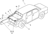
図1に示す荷台用カバー装置1は、車両の後方に設けられ上部が開口した荷台3と、該荷台3に開閉自在に設けられたテイルゲート4とを備えた車両2に用いられる。
A loading
前記荷台3の外側はサイドパネル5で囲まれている。このサイドパネル5の内側には、長尺状の支持部材6が設けられる。前記支持部材6上に前記荷台3を覆うカバー部材7を有する荷台用カバー装置1が載置される。
The outside of the
荷台用カバー装置1は、前記荷台を覆い着脱自在に設けられるカバー部材7と、前記荷台3にカバー部材7を固定するロック手段とからなる。
The
前記カバー部材7は、複数に分割された矩形状の板部材で、カバー部材7の略中央部に設けられている回動支持部材9により上方に向けて屈曲自在に構成されている。前記ロック手段は、前記カバー部材7を前記荷台3に係脱可能に固定する第1固定部材10と、前記テイルゲート4を前記カバー部材7に係脱可能に固定する第2固定部材11とからなる。前記第1固定部材10は、前記カバー部材7の後方、両側端部に設けられている。前記第2固定部材11は、前記カバー部材7に設けられた雄部材12とテイルゲート4に設けられた雌部材13とにより構成される。
The
前記テイルゲート4は、テイルゲート4を後方へ開放する上下開きを可能とさせる第1の支軸部材15がテイルゲート4の下端に設けられている。また、図2に示すようにテイルゲート4には、テイルゲート4を左右のいずれかへ開放する横開きを可能とさせるヒンジ部材である第2の支軸部材16がテイルゲート4の側方の一側に設けられている。尚、前記第2固定部材11は、前記第2の支軸部材16の反対側、すなわち前記テイルゲート4に設けられた第2の支軸部材16が設けられていない他側に設けられる。
The
図3は、第1固定部材10を示す斜視図である。前記第1固定部材10は、レバー17と、このレバー17をカバー部材7の裏面に回動自在に固定する支軸固定部18とからなる。荷台3のサイドパネル5内側には、ベッドレール19が設けられている。
FIG. 3 is a perspective view showing the
図4は第2固定部材11を構成する雄部材12を示す斜視図である。前記雄部材12は、係合部材21と雄用付勢部材22とからなる。前記係合部材21は、第1のベースブラケット23と、雄ブラケット24とからなる。
FIG. 4 is a perspective view showing the
第1のベースブラケット23は、矩形状の板部材であり、カバー部材7の裏面にボルト25で固定される。雄ブラケット24は、先端に係合部26を有し、基端において前記第1のベースブラケット23と第1のヒンジ27によって回動自在に連結されている。前記係合部26は、下方に突出して形成される。
The
前記雄用付勢部材22は、T字形の板部材であり、前記係合部材21の後方においてカバー部材7の裏面にボルト25で固定される基部30を基端に備え、先端に設けられた付勢片31と、この付勢片31を上方に付勢する付勢部32を備える。前記雄用付勢部材22は、横長の矩形部材である前記基部30の略中央から縦長形状の矩形部材が斜め下方に伸び、緩やかな円弧状に形成された前記付勢部32が設けられ、この付勢部32の先に直線状の付勢片31が一体的に形成されている。
The
図5は、施錠装置35を示す斜視図である。施錠装置35は、キーボックス36と、該キーボックス36内に設けられたプッシュ式のキーシリンダ37と、該プッシュ式のキーシリンダ37内に設けられる上下方向に摺動自在の中筒38と、該中筒38を突出させ又は収納させるキー39と、前記施錠装置35を上方から覆い前記キーボックス36に係合する蓋体40とからなる。このように構成された施錠装置35は、図6に示すように、前記雄部材12の上方に設置され、カバー部材7に固設されている。
FIG. 5 is a perspective view showing the
図7は、第2固定部材11を構成する雌部材13を示す斜視図である。前記雌部材13は、第2のベースブラケット42と雌ブラケット43と固定部材44と雌用付勢部材45とからなる。
FIG. 7 is a perspective view showing the
図8は、雌部材13の側面図であり、(a)は使用状態、(b)不使用状態を示す図である。第2のベースブラケット42は、テイルゲート4の内壁に沿って延びるベース47と、ベース47の略中央を垂直に切り起して形成された固定部48と、ベース47から直角に曲げ形成された当接部49と、テイルゲート4に狭持される屈曲部50と、前記ベース47と略平行に立設された立設部51とにより構成される。
FIG. 8 is a side view of the
前記固定部材44は、板状部材で構成され、先端でテイルゲート4にボルト25で固定され、基端には、前記第2のベースブラケット42が挿通する貫通穴52が設けられている。
The
雌ブラケット43は、略矩形状の板部材で、先端側を斜め方向に曲げ形成することにより空間を形成した指掛部54と、板部材の略中央に形成された受部55と、垂直に切り起して形成されたストッパ部56と、基端側において円弧状に湾曲形成された後端部57とにより構成される。この雌ブラケット43は、基端において前記固定部材44と第2のヒンジ58によって回動自在に連結されている。
The
雌用付勢部材45は、断面が略S字形の板状弾性部材であり、前記第2のベースブラケット42に設けられた固定部48にリベット61などにより固定される底部62を基端に備え、先端に設けられた弾性片63と、この弾性片63をストッパ部56の表面に向かって付勢する弾性部64とを備える。雌用付勢部材45は、前記固定部62から略垂直方向に立上形成されると共に、弾性部64がS字形に形成され、この弾性部64の先に直線状に形成され前記第2のヒンジ58側へやや傾斜した前記弾性片63が設けられる。
The
次に上記構成について図を参照して説明する。 Next, the above configuration will be described with reference to the drawings.
まず、第1固定部材10によりカバー部材7が荷台3に固定される場合について説明する。図1に示すように、カバー部材7は荷台3のサイドパネル5に設けられた支持部材6上に載置する。支持部材6上にカバー部材7を載置した後、図3に示すように、カバー部材7裏面に設けられた第1固定部材10のレバー17を回動し、ベッドレール19にレバー17先端を係合させる。レバー17先端がベッドレール19に係合するとカバー部材7が荷台3のサイドパネル5に固定される。
First, the case where the
次いで、第2固定部材11によりテイルゲート4が荷台3に固定される場合について説明する。
Next, the case where the
まず、図9に示すように、畳んだ状態の雌ブラケット43を使用状態にする。すなわち、テイルゲート4に設けられた第2固定部材11を構成する雌部材13において、雌ブラケット43の指掛部54が上方に持ち上げられる。指掛部54が上方に持ち上げられると、雌ブラケット43が第2のヒンジ58を中心に回動し引き起こされる。雌ブラケット43が引き起こされると、図8(a)に示すように、雌ブラケット43に形成されたストッパ部56が、第2のベースブラケット42に固定された雌用付勢部材45に設けられた付勢片63に当接する。さらに雌ブラケット43が引き起こされると、雌ブラケット43の基端側に形成された後端部57が、第2のベースブラケット42に設けられた立設部51に当接し、雌ブラケット43の回動が制止される。基端部が立設部51に当接すると、雌ブラケット43は中央に形成された受部55が略垂直方向に開口した状態で固定される。雌ブラケット43は、雌用付勢部材45に設けられた付勢片63とストッパ部56が面接触し、付勢片63がストッパ部56に押付けられているので、接触面に摩擦力が生じ、この摩擦力により雌ブラケット43が倒れるのを防止できる。さらに、固定部材44がテイルゲート4にボルト25で固定されており、第2のベースブラケット42が当接部49で前記固定部材44により固定されているので、荷物を荷台3から引き出す際に、荷物が雌ブラケット43に引っ掛っても、テイルゲート4から雌部材13が外れてしまうことを防止できる(図8(b))。また、不使用時には、図9に示すように、雌ブラケット43をテイルゲート4表面と略平行に畳んでおけるので、荷台3への荷物の出し入れなどの際、邪魔になることを防ぐことができる。また、雌ブラケット43は、畳んだ状態で先端に向かって斜方に傾斜し、先端がテイルゲート4の内壁表面に接するように形成されているので、荷物を荷台3から引き出す際、荷物が雌ブラケット43上に乗り上げることができ、荷物を傷つけることなく、円滑に荷物を引き出すことができる。
First, as shown in FIG. 9, the folded
次いで、図10に示すように、雌ブラケット43を起した状態のままテイルゲート4が閉じられる。雌ブラケット43を起した状態のままテイルゲート4が閉じられると、図11に示すように、キーシリンダ37にキー39が差し込まれ、中筒38が突出する。中筒38が突出すると、図12に示すように、中筒38は雄ブラケット24に当接し、雄用付勢部材22に抗して雄ブラケット24を押し下げる。中筒38が雄ブラケット24を押し下げると、雄ブラケット24の先端に形成された下方に突出した係合部26が、雌ブラケット43に形成された受部55に係合する。これにより、第2固定部材11によりテイルゲート4がカバー部材7に固定される。
Next, as shown in FIG. 10, the
このように、テイルゲート4が、荷台3のサイドパネル5に独立して固定される施錠手段を有しない場合であっても、カバー部材7を第1固定部材10により荷台3に固定し、テイルゲート4を第2固定部材11によりにカバー部材7に固定することにより、荷台3を確実に施錠することができる。
Thus, even if the
さらに、図13に示すように、施錠装置35のキーシリンダ37からキー39が抜かれ、蓋体40が被せられる。こうすることにより、キーシリンダ37の防水をはかり、さらに異物の混入などによる不具合を防止できる。
Further, as shown in FIG. 13, the key 39 is removed from the
上記のように雄ブラケット24は、不使用時には、雄用付勢部材22により、上方すなわちカバー部材7の裏面に当接した状態に保持されているので、荷台3をカバー部材7で覆った状態で荷物を出し入れする場合にも雄部材12が邪魔になることがない。また、雄ブラケット24は付勢部32材によりカバー部材7に押付けられ、カバー部材7に一体化されているので、回動支持部材9によりカバー部材7を上方に向かって屈曲させることができる。さらに、第2の固定部材44は、第2の支軸部材16が設けられていない他側に設けることとしたことにより、上下開きおよび横開きの両方において施錠を可能とすることができる。
As described above, when not in use, the
上記のように本実施形態では、車両1の後方に設けられ上部が開口した荷台3と、該荷台3に開閉自在に設けられたテイルゲート4とを備えた車両1に用いられ、前記荷台3を覆い着脱自在に設けられるカバー部材7を有する荷台用カバー装置1において、前記カバー部材7を前記荷台3に係脱可能に固定する第1固定部材10と、前記テイルゲート4を前記カバー部材7に係脱可能に固定する第2固定部材11とを備え、前記第1固定部材10は前記カバー部材7の内側に設けられており、前記第2固定部材11は前記テイルゲート4を前記カバー部材7に対し施錠する施錠装置35を備えることにより、カバー部材7が荷台3にロックされると共に、テイルゲート4をロックすることができるので、車両1がテイルゲート4に固定手段を備えていない場合においても、車両1における荷台3を施錠することができる。
As described above, in this embodiment, the present invention is used in a
また、前記テイルゲート4は前記テイルゲート4を開閉自在にする第2の支軸部材16が一側に設けられており、前記第2固定部材11は、前記第2の支軸部材16の反対側に設けられることにより、第2固定部材11が第2の支軸部材16から離れた位置にあるので、第2固定部材11に作用する荷重を小さくできるので、第2固定部材11を小型化することができると共に、破損を防止し確実に施錠することができる。
Further, the
本発明は、本実施形態に限定されるものではなく、本発明の要旨の範囲内で種々の変形実施が可能である。 The present invention is not limited to this embodiment, and various modifications can be made within the scope of the gist of the present invention.
1 荷台用カバー装置
2 車両
3 荷台
4 テイルゲート
7 カバー部材
8 荷台用カバー装置
10 第1固定部材
11 第2固定部材
16 第2の支軸部材(ヒンジ部材)
35 施錠装置
DESCRIPTION OF
10 First fixing member
11 Second fixing member
16 Second spindle member (hinge member)
35 Locking device
Claims (2)
前記カバー部材を前記荷台に係脱可能に固定する第1固定部材と、
前記テイルゲートを前記カバー部材に係脱可能に固定する第2固定部材と
を備え、
前記第1固定部材は前記カバー部材の内側に設けられており、
前記第1固定部材のレバーは前記カバー部材の内側に設けられており、
前記テイルゲートは前記テイルゲートを左右方向に開閉自在にするヒンジ部材が一側に設けられており、
前記第2固定部材は、前記ヒンジ部材の反対側に設けられ、前記テイルゲートを前記カバー部材に対し施錠する施錠装置を有し、
前記施錠装置が前記カバー部材に設けられている
ことを特徴とする荷台用カバー装置。 A cover device for a cargo bed, which is used in a vehicle including a cargo bed provided at the rear of the vehicle and having an open top and a tailgate that is freely opened and closed on the cargo bed, and has a cover member that covers the cargo bed and is detachably provided. In
A first fixing member for releasably fixing the cover member to the cargo bed;
A second fixing member for releasably fixing the tailgate to the cover member;
The first fixing member is provided inside the cover member;
The lever of the first fixing member is provided inside the cover member;
The tail gate is provided on one side with a hinge member that allows the tail gate to be opened and closed in the left-right direction.
The second fixing member is provided on the opposite side of the hinge member, and has a locking device that locks the tailgate to the cover member,
The loading platform cover device, wherein the locking device is provided on the cover member .
前記雄部材は、前記雌部材に係合する雄ブラケットが雄用付勢部材により前記カバー部材の裏面に当接した状態に保持されてなり、
前記施錠手段によって前記雄ブラケットを押すことにより前記雌部材に前記雄ブラケットを係合させて施錠する
ことを特徴とする請求項1記載の荷台用カバー装置。 The second fixing member has a male member and a female member provided on the inner wall of the tailgate,
The male member is held in a state where a male bracket that engages the female member is in contact with the back surface of the cover member by a male biasing member,
The loading platform cover apparatus according to claim 1 , wherein the male bracket is engaged with the female member and locked by pushing the male bracket by the locking means .
Priority Applications (3)
| Application Number | Priority Date | Filing Date | Title |
|---|---|---|---|
| JP2005042714A JP4432116B2 (en) | 2005-02-18 | 2005-02-18 | Cargo cover device |
| US11/350,015 US7506913B2 (en) | 2005-02-18 | 2006-02-09 | Bed covering apparatus |
| CNB2006100078209A CN100400336C (en) | 2005-02-18 | 2006-02-17 | Bed covering apparatus |
Applications Claiming Priority (1)
| Application Number | Priority Date | Filing Date | Title |
|---|---|---|---|
| JP2005042714A JP4432116B2 (en) | 2005-02-18 | 2005-02-18 | Cargo cover device |
Publications (2)
| Publication Number | Publication Date |
|---|---|
| JP2006224861A JP2006224861A (en) | 2006-08-31 |
| JP4432116B2 true JP4432116B2 (en) | 2010-03-17 |
Family
ID=36911910
Family Applications (1)
| Application Number | Title | Priority Date | Filing Date |
|---|---|---|---|
| JP2005042714A Expired - Fee Related JP4432116B2 (en) | 2005-02-18 | 2005-02-18 | Cargo cover device |
Country Status (3)
| Country | Link |
|---|---|
| US (1) | US7506913B2 (en) |
| JP (1) | JP4432116B2 (en) |
| CN (1) | CN100400336C (en) |
Families Citing this family (5)
| Publication number | Priority date | Publication date | Assignee | Title |
|---|---|---|---|---|
| US8061753B2 (en) | 2009-01-20 | 2011-11-22 | Ford Global Technologies, Llc | Universal tailgate hinge |
| US9938753B1 (en) * | 2017-01-27 | 2018-04-10 | Ford Global Technologies Llc | Lock mechanism assembly for vehicle tailgate |
| US11465477B2 (en) | 2018-05-02 | 2022-10-11 | Abc Technologies Inc. | Tonneau cover |
| WO2019213314A1 (en) | 2018-05-02 | 2019-11-07 | Abc Technologies Inc. | Tonneau cover |
| US11577592B2 (en) * | 2020-09-09 | 2023-02-14 | Ford Global Technologies, Llc | Continuous sealing flat assembly for unibody truck cargo box |
Family Cites Families (65)
| Publication number | Priority date | Publication date | Assignee | Title |
|---|---|---|---|---|
| US3012814A (en) * | 1958-11-14 | 1961-12-12 | Evert J Amick | Cover and deck structure for pick-up trucks |
| US3489456A (en) * | 1968-05-08 | 1970-01-13 | Roy A Klanke | Cargo compartment cover for pickup truck |
| US3762762A (en) * | 1971-05-28 | 1973-10-02 | T Beveridge | Cover and lifting mechanism for pick ups |
| US3923334A (en) * | 1974-03-22 | 1975-12-02 | Hugh L Key | Vehicle bed cover assembly |
| US3950010A (en) * | 1975-01-29 | 1976-04-13 | Ronbil Industries, Inc. | Tie-down clamp assembly for truck vehicle bed |
| US4083596A (en) * | 1976-04-23 | 1978-04-11 | Ronbil Industries | Raisable topper |
| US4124247A (en) * | 1976-11-19 | 1978-11-07 | Penner Benjamin L | Quick detachable hinging structure |
| US4294484A (en) * | 1979-03-09 | 1981-10-13 | Ronbil Industries, Inc. | Vehicle camper |
| US4418954A (en) * | 1980-07-28 | 1983-12-06 | Buckley John A | Foldable cover for a truck bed |
| US4522440A (en) * | 1983-07-11 | 1985-06-11 | Gostomski Richard B | Raisable cover |
| US5251951A (en) * | 1984-09-14 | 1993-10-12 | Wheatley Donald G | Tonneau cover and support means |
| JPS6456281U (en) | 1987-10-02 | 1989-04-07 | ||
| US5183309A (en) * | 1991-09-24 | 1993-02-02 | Jordan Gregory E | Rigid low profile pickup tonneau |
| US5636893A (en) * | 1995-04-17 | 1997-06-10 | Wheatley; Donald E. | Folding hard panel tonneau cover with rail attachment |
| US5688017A (en) * | 1995-06-07 | 1997-11-18 | Bennett; Bruce A. | Method and apparatus for mounting framed tonneau cover |
| CA2178224C (en) * | 1996-06-07 | 2000-10-31 | Robert B. Karrer | Modular cargo anchoring and protection system for pickup trucks |
| US5971469A (en) * | 1996-11-01 | 1999-10-26 | Lund Industries, Incorporated | Pickup truck cab extending tonneau cover |
| US5857729A (en) * | 1997-03-21 | 1999-01-12 | Bogard; Donald E. | Pick-up truck cover |
| US5931521A (en) * | 1997-05-29 | 1999-08-03 | Kooiker; John | Folding cover for pickup truck bed |
| US6203086B1 (en) * | 1997-11-04 | 2001-03-20 | Coeur D'alene Patent Investment Llc | Tool box and top cover for truck box |
| US6186576B1 (en) * | 1997-11-19 | 2001-02-13 | Bruce L. Kepley | Bedcover suspension/access system |
| US6109681A (en) * | 1998-09-21 | 2000-08-29 | Custom Fibreglass Manufacturing Co. | Tonneau cover mounting system |
| US6076881A (en) * | 1998-10-07 | 2000-06-20 | Design Automotive Group, Inc. | Flip hatch tonneau cover |
| US6427500B1 (en) * | 1998-11-09 | 2002-08-06 | The Eastern Company | Latch, lock and hinge system for use with closures such as tonneau covers |
| WO2000047436A1 (en) * | 1999-02-09 | 2000-08-17 | Decoma Exterior Trim Inc. | Mounting hardware for a hard tonneau cover |
| US6340194B1 (en) * | 1999-06-25 | 2002-01-22 | Stk, Llc | Hard truck bed cover |
| US6234560B1 (en) * | 1999-08-13 | 2001-05-22 | General Motors Corporation | Cargo cover |
| US6338520B2 (en) * | 1999-09-02 | 2002-01-15 | The Budd Company | Tonneau cover and attachment assembly |
| US6183035B1 (en) * | 1999-09-02 | 2001-02-06 | The Budd Company | Tonneau cover and attachment assembly |
| US6322128B1 (en) * | 1999-10-29 | 2001-11-27 | Robert Karrer | Cargo bed attachment for trucks |
| US6299232B1 (en) * | 1999-11-01 | 2001-10-09 | Edgar Davis | Removeable vehicle bed cover |
| US6422635B1 (en) * | 2000-01-20 | 2002-07-23 | Steffens Enterprises, Inc. | Folding cargo bay cover for pickup truck |
| WO2001053126A1 (en) * | 2000-01-20 | 2001-07-26 | The Budd Company | Tonneau cover stake pocket attachment system and tailgate interlock |
| US6588826B1 (en) * | 2000-02-29 | 2003-07-08 | Scott Arthur William Muirhead | Rigid cover assembly for a pickup truck |
| US6343828B1 (en) * | 2000-07-10 | 2002-02-05 | David C. Young | Truck lid hinge and opener system |
| US6447045B1 (en) * | 2000-07-17 | 2002-09-10 | Algonquin International Industries, Inc. | Tonneau cover mounting system |
| US6382699B1 (en) * | 2000-07-19 | 2002-05-07 | The Budd Company | Tonneau cover bumper |
| CN2477470Y (en) * | 2001-06-08 | 2002-02-20 | 赵永胜 | Wholly enclosed appts. of cargo car body |
| WO2003001013A2 (en) * | 2001-06-22 | 2003-01-03 | Decoma International Inc. | Hinge for a tonneau cover |
| US6572174B2 (en) * | 2001-09-24 | 2003-06-03 | Javier Hernandez | Vehicle structure |
| CN2513834Y (en) * | 2001-12-25 | 2002-10-02 | 赵永胜 | Covering for cargo car body |
| US6497445B1 (en) * | 2001-12-27 | 2002-12-24 | Astro Cap Manufacturing West, Inc. | Hard tonneau cover with concealed exterior latch handle |
| US6588825B1 (en) * | 2002-04-26 | 2003-07-08 | Donald G. Wheatley | Rain diverting device for a tonneau cover system |
| US6616210B1 (en) * | 2002-05-29 | 2003-09-09 | Jerry R. Massey | Pickup truck bed cover |
| US6820915B2 (en) * | 2002-07-24 | 2004-11-23 | Daimlerchrysler Corporation | Convertible cover arrangement for vehicle cargo area |
| US6742832B1 (en) * | 2002-08-30 | 2004-06-01 | Ford Global Technologies, Llc | Vehicle bed assembly and a method for making a vehicle bed assembly |
| US6641201B1 (en) * | 2002-09-17 | 2003-11-04 | General Motors Corporation | Convertible bed cover for a vehicle |
| US7258387B2 (en) * | 2002-11-04 | 2007-08-21 | Ross Weldy | Clamp for a tonneau cover |
| US6764125B2 (en) * | 2002-11-06 | 2004-07-20 | Bauer Products, Inc. | Prop assembly for vehicle bed covers and the like |
| US6702360B1 (en) * | 2003-01-03 | 2004-03-09 | Custom Fibreglass Manufacturing Co. | Tonneau cover mounting mechanism |
| US7252322B2 (en) * | 2003-02-07 | 2007-08-07 | William Rusu | Hard tonneau cover |
| US7040675B1 (en) * | 2003-02-12 | 2006-05-09 | The Eastern Company | Linkage operated latching system |
| US6783169B1 (en) * | 2003-02-13 | 2004-08-31 | Webasto Sunroofs, Inc. | Cover assembly for a vehicle bed |
| US6883855B2 (en) * | 2003-04-01 | 2005-04-26 | Diamondback Automotive Accessories, Inc. | Hinged tonneau cover for transporting a significant top load |
| US7066523B2 (en) * | 2003-06-11 | 2006-06-27 | Asc Incorporated | Tonneau cover for automotive vehicle |
| US6908139B1 (en) * | 2003-12-30 | 2005-06-21 | William K. Szieff | Truck bed cover |
| US7052071B2 (en) * | 2004-05-27 | 2006-05-30 | Steffens Enterprises, Inc. | Cover and latch for vehicle cargo bed with tailgate |
| US7264297B2 (en) * | 2004-08-13 | 2007-09-04 | A.R.E. Accessories, Llc | Tonneau cover hinge |
| JP4247744B2 (en) * | 2004-09-06 | 2009-04-02 | 株式会社ホンダアクセス | Tonneau cover mounting structure for pickup truck |
| US7261328B2 (en) * | 2004-10-18 | 2007-08-28 | Fastec Industrial Corp. | Push button latch release assembly |
| US7374221B2 (en) * | 2004-11-12 | 2008-05-20 | Honda Motor Co., Ltd. | Cargo lid anchor cable |
| US20060208525A1 (en) * | 2005-03-16 | 2006-09-21 | Jonsson Stanley C | Tonneau truck cover opening system |
| US7188888B2 (en) * | 2005-05-31 | 2007-03-13 | Wheatley Donald G | Tonneau system latch |
| US7322633B2 (en) * | 2005-10-28 | 2008-01-29 | Penda Corporation | Releaseable hinge for truck bed cover |
| US20070170739A1 (en) * | 2006-01-26 | 2007-07-26 | Ford Global Technologies, Llc | Auxiliary storage system for automotive vehicle |
-
2005
- 2005-02-18 JP JP2005042714A patent/JP4432116B2/en not_active Expired - Fee Related
-
2006
- 2006-02-09 US US11/350,015 patent/US7506913B2/en active Active
- 2006-02-17 CN CNB2006100078209A patent/CN100400336C/en not_active Expired - Fee Related
Also Published As
| Publication number | Publication date |
|---|---|
| US7506913B2 (en) | 2009-03-24 |
| CN100400336C (en) | 2008-07-09 |
| JP2006224861A (en) | 2006-08-31 |
| CN1820979A (en) | 2006-08-23 |
| US20060186691A1 (en) | 2006-08-24 |
Similar Documents
| Publication | Publication Date | Title |
|---|---|---|
| JP4432116B2 (en) | Cargo cover device | |
| JP5005397B2 (en) | Vehicle gate opening and closing device | |
| EP1576874A1 (en) | Latch mechanism for hooded litter pan | |
| JP2003341431A (en) | Luggage floor device for automobile | |
| JP3723690B2 (en) | Console Box | |
| JP4290016B2 (en) | Slope device for vehicle | |
| JP4205085B2 (en) | Lid device | |
| JP2006056408A (en) | Slope formation device for vehicle | |
| JP4839732B2 (en) | Vehicle hood structure | |
| JP4384955B2 (en) | Gate lock device | |
| JP2011068309A (en) | Storage box | |
| KR200296037Y1 (en) | Drawer Bus Cargo Storage Box | |
| KR102721212B1 (en) | Tailgate locking apparatus of freight vehicle | |
| JP5660666B2 (en) | Cover opening / closing device | |
| JP3703628B2 (en) | Storage box | |
| JP2009078666A (en) | Gate lock device | |
| KR20170081483A (en) | Locking apparatus for cargo gate of truck | |
| JPH1134747A (en) | Lock structure for glove compartment | |
| JP2009006794A (en) | Cargo bed rear structure of vehicle | |
| JP5026139B2 (en) | Cover device in the trunk room | |
| JP2008013002A (en) | Load-carrying platform structure of vehicle | |
| JP4188066B2 (en) | Packing box sash door lashing equipment | |
| KR100863178B1 (en) | Car Luggage Box | |
| JP2010241219A (en) | Console box mounting structure | |
| JP2582283Y2 (en) | Hinge part structure of a rotatable article holder provided in a vehicle |
Legal Events
| Date | Code | Title | Description |
|---|---|---|---|
| A621 | Written request for application examination |
Free format text: JAPANESE INTERMEDIATE CODE: A621 Effective date: 20061110 |
|
| A977 | Report on retrieval |
Free format text: JAPANESE INTERMEDIATE CODE: A971007 Effective date: 20090331 |
|
| A131 | Notification of reasons for refusal |
Free format text: JAPANESE INTERMEDIATE CODE: A131 Effective date: 20090406 |
|
| A521 | Written amendment |
Free format text: JAPANESE INTERMEDIATE CODE: A523 Effective date: 20090603 |
|
| A131 | Notification of reasons for refusal |
Free format text: JAPANESE INTERMEDIATE CODE: A131 Effective date: 20090831 |
|
| A521 | Written amendment |
Free format text: JAPANESE INTERMEDIATE CODE: A523 Effective date: 20091027 |
|
| TRDD | Decision of grant or rejection written | ||
| A01 | Written decision to grant a patent or to grant a registration (utility model) |
Free format text: JAPANESE INTERMEDIATE CODE: A01 Effective date: 20091130 |
|
| A01 | Written decision to grant a patent or to grant a registration (utility model) |
Free format text: JAPANESE INTERMEDIATE CODE: A01 |
|
| A61 | First payment of annual fees (during grant procedure) |
Free format text: JAPANESE INTERMEDIATE CODE: A61 Effective date: 20091213 |
|
| R150 | Certificate of patent or registration of utility model |
Free format text: JAPANESE INTERMEDIATE CODE: R150 |
|
| FPAY | Renewal fee payment (event date is renewal date of database) |
Free format text: PAYMENT UNTIL: 20130108 Year of fee payment: 3 |
|
| FPAY | Renewal fee payment (event date is renewal date of database) |
Free format text: PAYMENT UNTIL: 20130108 Year of fee payment: 3 |
|
| FPAY | Renewal fee payment (event date is renewal date of database) |
Free format text: PAYMENT UNTIL: 20130108 Year of fee payment: 3 |
|
| FPAY | Renewal fee payment (event date is renewal date of database) |
Free format text: PAYMENT UNTIL: 20140108 Year of fee payment: 4 |
|
| LAPS | Cancellation because of no payment of annual fees |