JP4421956B2 - Substrate processing apparatus and processing method - Google Patents
Substrate processing apparatus and processing method Download PDFInfo
- Publication number
- JP4421956B2 JP4421956B2 JP2004191134A JP2004191134A JP4421956B2 JP 4421956 B2 JP4421956 B2 JP 4421956B2 JP 2004191134 A JP2004191134 A JP 2004191134A JP 2004191134 A JP2004191134 A JP 2004191134A JP 4421956 B2 JP4421956 B2 JP 4421956B2
- Authority
- JP
- Japan
- Prior art keywords
- substrate
- nozzles
- processing
- nozzle
- processing liquid
- Prior art date
- Legal status (The legal status is an assumption and is not a legal conclusion. Google has not performed a legal analysis and makes no representation as to the accuracy of the status listed.)
- Expired - Fee Related
Links
Images


Classifications
-
- G—PHYSICS
- G02—OPTICS
- G02F—OPTICAL DEVICES OR ARRANGEMENTS FOR THE CONTROL OF LIGHT BY MODIFICATION OF THE OPTICAL PROPERTIES OF THE MEDIA OF THE ELEMENTS INVOLVED THEREIN; NON-LINEAR OPTICS; FREQUENCY-CHANGING OF LIGHT; OPTICAL LOGIC ELEMENTS; OPTICAL ANALOGUE/DIGITAL CONVERTERS
- G02F1/00—Devices or arrangements for the control of the intensity, colour, phase, polarisation or direction of light arriving from an independent light source, e.g. switching, gating or modulating; Non-linear optics
- G02F1/01—Devices or arrangements for the control of the intensity, colour, phase, polarisation or direction of light arriving from an independent light source, e.g. switching, gating or modulating; Non-linear optics for the control of the intensity, phase, polarisation or colour
- G02F1/13—Devices or arrangements for the control of the intensity, colour, phase, polarisation or direction of light arriving from an independent light source, e.g. switching, gating or modulating; Non-linear optics for the control of the intensity, phase, polarisation or colour based on liquid crystals, e.g. single liquid crystal display cells
-
- H—ELECTRICITY
- H01—ELECTRIC ELEMENTS
- H01L—SEMICONDUCTOR DEVICES NOT COVERED BY CLASS H10
- H01L21/00—Processes or apparatus adapted for the manufacture or treatment of semiconductor or solid state devices or of parts thereof
- H01L21/67—Apparatus specially adapted for handling semiconductor or electric solid state devices during manufacture or treatment thereof; Apparatus specially adapted for handling wafers during manufacture or treatment of semiconductor or electric solid state devices or components ; Apparatus not specifically provided for elsewhere
- H01L21/67005—Apparatus not specifically provided for elsewhere
- H01L21/67011—Apparatus for manufacture or treatment
- H01L21/67017—Apparatus for fluid treatment
- H01L21/67028—Apparatus for fluid treatment for cleaning followed by drying, rinsing, stripping, blasting or the like
- H01L21/6704—Apparatus for fluid treatment for cleaning followed by drying, rinsing, stripping, blasting or the like for wet cleaning or washing
- H01L21/67051—Apparatus for fluid treatment for cleaning followed by drying, rinsing, stripping, blasting or the like for wet cleaning or washing using mainly spraying means, e.g. nozzles
-
- H—ELECTRICITY
- H01—ELECTRIC ELEMENTS
- H01L—SEMICONDUCTOR DEVICES NOT COVERED BY CLASS H10
- H01L21/00—Processes or apparatus adapted for the manufacture or treatment of semiconductor or solid state devices or of parts thereof
- H01L21/67—Apparatus specially adapted for handling semiconductor or electric solid state devices during manufacture or treatment thereof; Apparatus specially adapted for handling wafers during manufacture or treatment of semiconductor or electric solid state devices or components ; Apparatus not specifically provided for elsewhere
- H01L21/67005—Apparatus not specifically provided for elsewhere
- H01L21/67011—Apparatus for manufacture or treatment
- H01L21/6715—Apparatus for applying a liquid, a resin, an ink or the like
-
- G—PHYSICS
- G02—OPTICS
- G02F—OPTICAL DEVICES OR ARRANGEMENTS FOR THE CONTROL OF LIGHT BY MODIFICATION OF THE OPTICAL PROPERTIES OF THE MEDIA OF THE ELEMENTS INVOLVED THEREIN; NON-LINEAR OPTICS; FREQUENCY-CHANGING OF LIGHT; OPTICAL LOGIC ELEMENTS; OPTICAL ANALOGUE/DIGITAL CONVERTERS
- G02F2201/00—Constructional arrangements not provided for in groups G02F1/00 - G02F7/00
- G02F2201/54—Arrangements for reducing warping-twist
Landscapes
- Physics & Mathematics (AREA)
- Engineering & Computer Science (AREA)
- General Physics & Mathematics (AREA)
- Nonlinear Science (AREA)
- Condensed Matter Physics & Semiconductors (AREA)
- Manufacturing & Machinery (AREA)
- Computer Hardware Design (AREA)
- Microelectronics & Electronic Packaging (AREA)
- Power Engineering (AREA)
- Chemical & Material Sciences (AREA)
- Crystallography & Structural Chemistry (AREA)
- Optics & Photonics (AREA)
- Weting (AREA)
- Cleaning Or Drying Semiconductors (AREA)
- Cleaning By Liquid Or Steam (AREA)
- Container, Conveyance, Adherence, Positioning, Of Wafer (AREA)
Description
この発明は基板を処理液によって処理する場合に好適する基板の処理装置及び処理方法に関する。 The present invention relates to a substrate processing apparatus and a processing method suitable for processing a substrate with a processing liquid.
液晶表示装置に用いられるガラス製の基板には回路パターンが形成される。基板に回路パターンを形成するにはリソグラフィープロセスが採用される。リソグラフィープロセスは周知のように上記基板にレジストを塗布し、このレジストに回路パターンが形成されたマスクを介して光を照射する。 A circuit pattern is formed on a glass substrate used in the liquid crystal display device. A lithographic process is employed to form a circuit pattern on the substrate. As is well known, in the lithography process, a resist is applied to the substrate, and light is irradiated through a mask having a circuit pattern formed on the resist.
つぎに、レジストの光が照射されない部分或いは光が照射された部分を除去し、基板のレジストが除去された部分をエッチングし、エッチング後にレジストを除去するなどの一連の工程を複数回繰り返すことで、上記基板に回路パターンを形成する。 Next, by repeating a series of steps such as removing a portion of the resist not irradiated with light or a portion irradiated with light, etching the portion of the substrate where the resist is removed, and removing the resist after etching, a plurality of times. Then, a circuit pattern is formed on the substrate.
このようなリソグラフィープロセスにおいては、上記基板に現像液、エッチング液或いはエッチング後にレジストを除去する剥離液などの処理液によって基板を処理する工程、さらに処理液としての洗浄液によって洗浄する工程などがあり、洗浄後には基板に付着残留した洗浄液を除去する乾燥工程が必要となる。 In such a lithography process, there are a step of treating the substrate with a processing solution such as a developing solution, an etching solution or a stripping solution for removing the resist after etching, and a step of washing with a cleaning solution as a processing solution. After the cleaning, a drying process for removing the cleaning liquid remaining on the substrate is required.
従来、基板に対して上述した一連の処理を行う場合、上記基板は軸線を水平にして配置された搬送ローラによって水平な状態でそれぞれの処理チャンバに順次搬送し、そこで処理液によって処理したり、圧縮気体を噴射して乾燥処理するようにしている。 Conventionally, when the above-described series of processing is performed on a substrate, the substrate is sequentially transported to each processing chamber in a horizontal state by a transport roller disposed with the axis line horizontal, and processed with a processing liquid there, A drying process is performed by injecting compressed gas.
ところで、最近では液晶表示装置に用いられるガラス製の基板が大型化及び薄型化する傾向にある。そのため、基板を水平搬送すると、搬送ローラ間における基板の撓みが大きくなるため、各処理チャンバでの処理が基板の板面全体にわたって均一に行えなくなるということが生じる。 Recently, glass substrates used in liquid crystal display devices tend to be larger and thinner. For this reason, when the substrate is horizontally transported, the bending of the substrate between the transport rollers becomes large, so that processing in each processing chamber cannot be performed uniformly over the entire plate surface of the substrate.
基板が大型化すると、その基板を搬送する搬送ローラが設けられた搬送軸が長尺化する。しかも、基板が大型化することで、基板上に供給される処理液が増大し、基板上の処理液の量に応じて上記搬送軸に加わる荷重が大きくなるから、それらのことによって搬送軸の撓みが増大する。そのため、基板は搬送軸が撓むことによっても撓みが生じ、均一な処理が行えなくなるということがある。 When the substrate is enlarged, the transport shaft provided with the transport roller for transporting the substrate becomes longer. In addition, since the substrate is increased in size, the processing liquid supplied onto the substrate is increased, and the load applied to the transport shaft is increased according to the amount of the processing liquid on the substrate. Deflection increases. Therefore, the substrate may be bent even when the transport shaft is bent, and uniform processing may not be performed.
そこで、処理液によって基板を処理する際、上記基板が処理液の重量によって撓むのを防止するため、基板を所定の角度、たとえば70度程度の角度で起立させて搬送するということが考えられている。基板を起立させた立位状態で搬送すれば、処理液は基板の板面に溜まらず、上方から下方へ円滑に流れるから、処理液の重量によって基板が撓むのを防止することができる。 Therefore, when processing the substrate with the processing liquid, in order to prevent the substrate from bending due to the weight of the processing liquid, it is conceivable that the substrate is erected at a predetermined angle, for example, an angle of about 70 degrees. ing. If the substrate is transported in an upright position, the processing liquid does not accumulate on the plate surface of the substrate and smoothly flows from the upper side to the lower side, so that the substrate can be prevented from being bent by the weight of the processing liquid.
立位状態の基板に処理液を供給する場合、たとえば基板の上下方向の複数箇所からそれぞれノズルによって処理液を供給するということが考えられる。しかしながら、処理液を複数のノズルによって基板の板面に単に供給するだけでは、基板の上部に供給された処理液が基板の上部を処理した後、基板の下部に供給された処理液に混合して反応性が劣化するから、基板の下部の処理が上部に比べて劣るということがある。しかも、基板の上部と下部とを流れる処理液の速度は、高さの違いによって異なるから、その速度差によって基板の上部と下部とが均一に処理されないなどのことが生じる。 When supplying the processing liquid to the standing substrate, for example, it is conceivable that the processing liquid is supplied from a plurality of locations in the vertical direction of the substrate by nozzles. However, simply supplying the processing liquid to the substrate surface of the substrate with a plurality of nozzles causes the processing liquid supplied to the upper part of the substrate to be processed into the processing liquid supplied to the lower part of the substrate after processing the upper part of the substrate. As a result, the processing of the lower part of the substrate may be inferior to the upper part. Moreover, since the speed of the processing liquid flowing through the upper and lower portions of the substrate varies depending on the difference in height, the upper and lower portions of the substrate are not uniformly processed due to the difference in speed.
この発明は、基板を立位状態で搬送して処理液で処理する場合、この基板を全体にわたってほぼ均一に処理することができるようにした基板の処理装置及び処理方法を提供することにある。 It is an object of the present invention to provide a substrate processing apparatus and a method for processing a substrate so that the substrate can be processed almost uniformly over the entire substrate when the substrate is transported in a standing state and processed with a processing liquid.
この発明は、基板を処理液によって処理する処理装置において、
上記基板を立位状態で所定方向に搬送する搬送手段と、
この搬送手段によって立位状態で搬送される基板に処理液を噴射する処理部とを有し、
上記処理部は、上記基板の板面に処理液を噴射する複数のノズルを有し、これら複数のノズルは上記基板の高さ方向に所定間隔で、かつ高さ方向上方に位置するノズルが下方に位置するノズルよりも上記基板の搬送方向後方に位置するよう配置され、
上記基板の搬送方向において隣り合うノズルは、それぞれのノズルから噴射されて基板の板面に沿って流れる処理液の領域が重ならない間隔に設定されているとともに、高さ方向上方に位置するノズルは、下方に位置するノズルよりも、処理液の噴射量が大きく設定されることを特徴とする基板の処理装置にある。
The present invention provides a processing apparatus for processing a substrate with a processing liquid,
Conveying means for conveying the substrate in a predetermined direction in a standing position;
A processing unit for injecting the processing liquid onto the substrate transported in a standing state by the transporting means,
The processing unit has a plurality of nozzles for injecting a processing liquid onto the plate surface of the substrate, and the plurality of nozzles are arranged at predetermined intervals in the height direction of the substrate and the nozzles located above the height direction are below It is arranged so as to be located behind the nozzle in the transport direction of the substrate ,
The nozzles adjacent to each other in the substrate transport direction are set at intervals at which the regions of the processing liquid ejected from the respective nozzles and flowing along the plate surface of the substrate do not overlap, and the nozzles located above the height direction are The substrate processing apparatus is characterized in that the injection amount of the processing liquid is set larger than that of the nozzle located below .
上記ノズルは、噴射される処理液が放物線を描くよう噴射方向を斜め上方に向けるとともに、処理液は放物線の頂点の部分が基板の板面に当たる位置に配置されていることが好ましい。 The nozzle preferably directs the spraying direction obliquely upward so that the sprayed processing liquid draws a parabola, and the processing liquid is disposed at a position where the apex of the parabola hits the plate surface of the substrate.
この発明は、複数のノズルを基板の高さ方向に沿って配置し、これらノズルから処理液を噴射して基板を処理する処理方法において、
上記基板を立位状態で所定方向に搬送する搬送工程と、
高さ方向上方に位置するノズルを下方に位置するノズルよりも上記基板の搬送方向後方に位置させ、高さ方向上方に位置するノズルから噴射される処理液の噴射量を、下方に位置するノズルよりも大きく設定して立位状態で搬送される基板に複数のノズルから処理液を噴射するとともに、各ノズルから噴射されて基板の板面に沿って流れ落ちるそれぞれの処理液の領域が重ならないようにする噴射工程と
を具備したことを特徴とする基板の処理方法にある。
The present invention provides a processing method in which a plurality of nozzles are arranged along the height direction of a substrate, and a processing liquid is ejected from these nozzles to process the substrate.
A transporting step of transporting the substrate in a predetermined direction in a standing position;
The nozzle located above the height direction is positioned behind the nozzle located below the substrate in the transport direction of the substrate, and the amount of processing liquid sprayed from the nozzle located above the height direction is set below the nozzle. The processing liquid is sprayed from a plurality of nozzles onto a substrate that is set larger than the substrate and is transported in a standing position, and the regions of the processing liquid sprayed from the nozzles and flowing down along the plate surface of the substrate do not overlap. A substrate processing method comprising: an injection step.
この発明によれば、各ノズルから基板に噴射される処理液を混合させずに基板の上部から下部へ流すことができるため、それぞれのノズルから噴射された処理液に他のノズルから噴射された処理液が混合して反応性が劣化するということがない。そのため、立位状態で搬送される基板を複数のノズルから噴射される処理液によってほぼ均一に処理することが可能となる。 According to this invention, since the processing liquid sprayed from each nozzle to the substrate can be flowed from the upper part to the lower part without mixing, the processing liquid sprayed from each nozzle is sprayed from the other nozzles. There is no case where the processing liquid is mixed and the reactivity is deteriorated. Therefore, it becomes possible to process the substrate transported in the standing position substantially uniformly with the processing liquid ejected from the plurality of nozzles.
以下、図面を参照しながらこの発明の一実施の形態を説明する。 An embodiment of the present invention will be described below with reference to the drawings.
図1乃至図8はこの発明の第1の実施の形態を示す。図1に示す処理装置は基台1を備えている。この基台1の上面の長手方向一端部には幅方向に離間してローダ部2とアンローダ部3とが設けられている。ローダ部2とアンローダ部3とは矩形板状の受け部材4を有し、この受け部材4は下端部を支点として矢印で示す基台1の幅方向に沿って揺動駆動可能となっている。
1 to 8 show a first embodiment of the present invention. The processing apparatus shown in FIG. 1 includes a base 1. A
ローダ部2とアンローダ部3との一側面(ローダ部2のみ図示)の下端部には複数の下部受けローラ5が所定間隔で設けられ、上端部には複数の上部受けローラ6が所定間隔で設けられている。下部受けローラ5は図示しない駆動源によって回転駆動されるようになっている。
A plurality of lower receiving rollers 5 are provided at predetermined intervals on the lower end of one side surface of the
上記ローダ部2には未処理の基板Wが図示しない供給部から立位状態で供給される。ローダ部2に供給された基板Wは下端が下部受けローラ5に係合支持され、上端が上部受けローラ6に係合支持される。そして、未処理の基板Wは下部受けローラ5が所定方向に回転駆動されることで、後述する処理ステーションに供給される。
An unprocessed substrate W is supplied to the
上記処理ステーションで処理された基板Wは上記アンローダ部3に搬出される。アンローダ部3に搬出された基板Wは下端が下部受けローラ5に係合支持され、上端が上部受けローラ6に係合支持される。
The substrate W processed at the processing station is carried out to the
上記基台1のローダ部2とアンローダ部3を除く部分は鎖線で示すカバー7によって覆われている。このカバー7内には、基台1の長手方向に沿って処理ステーションとしての固定ステーション8と、同じく処理ステーションとしての回転ステーション9とが順次一列に設けられている。
A portion of the base 1 excluding the
上記固定ステーション8と回転ステーション9との一側面と他側面にはそれぞれ搬送手段10が設けられている。この搬送手段10は各ステーション8,9の下端部に幅方向に沿って所定間隔で設けられた駆動ローラ13を有する。この駆動ローラ13は駆動源12によって回転駆動される。各駆動ローラ13の上方にはそれぞれ上下方向に沿って所定間隔で設けられた複数、この実施の形態では3つの受けローラ14が設けられている。
上記駆動ローラ13は、詳細は図示しないが外周面にV溝が形成されているとともに回転軸線を水平にして設けられ、上記受けローラ14は回転軸線を垂直にして設けられている。
Although not shown in detail, the
上下方向に位置する3つの受けローラ14はそれぞれ各ステーション8,9の側面に突設された取付け部材15の先端部に設けられている。上下方向に沿って設けられた3つの受けローラ14は上方に行くにつれてステーション8,9の側面からの突出距離が小さくなるよう設定されている。
The three
それによって、上記ローダ部2から上記固定ステーション8の一側面に供給される基板Wは、下端が駆動ローラ13のV溝に係合し、一側面が上記受けローラ14に支持されることで、上端が下端よりも各ステーション8,9の側面側に所定の角度で傾斜した状態で上記駆動ローラ13によって搬送される。
Accordingly, the substrate W supplied from the
上下方向に位置する3つの受けローラ14は、下端が駆動ローラ13に支持された基板Wをたとえば70〜85度の角度で傾斜させて保持するよう、各ステーション8,9の側面からの突出距離が設定されている。基板Wを70〜85度の角度で傾斜させると、傾斜方向と逆方向に倒れることなく安定した状態で搬送することが可能となる。しかも、基板Wは、水平に搬送される場合のように自重によって撓むのが防止される。この実施の形態では、上記基板Wは75度の角度で傾斜して搬送されるようになっている。
The three
上記ローダ部2から固定ステーション8の一側面の搬送手段10に基板Wを供給する場合、ローダ部2の受け部材4を固定ステーション8に保持される基板Wの傾斜角度と同じ角度で傾斜させることで、ローダ部2から固定ステーション8の一側面に基板Wを円滑に受け渡すことができる。
When the substrate W is supplied from the
同様に、固定ステーション8の他側面からアンローダ部3に基板Wを搬出する場合、このアンローダ部3の受け部材4を基板Wと同じ角度で傾斜させておけば、上記固定ステーション8の他側面から上記アンローダ部3へ基板Wを円滑に受け渡すことができる。
Similarly, when the substrate W is carried out from the other side of the fixed station 8 to the
上記固定ステーション8の一側面には、処理手段としてそれぞれブラシ洗浄部17、処理部としてのエッチング処理部18及び純水洗浄部19が順次設けられ、上記回転ステーション9の一側面と他側面とにはそれぞれ処理手段としての乾燥処理部20(一方のみ図示)が設けられている。
On one side of the fixed station 8, a
上記ブラシ洗浄部17は、詳細は図示しないが無端状をなし、基板Wの上下方向に沿って無端走行する一対のベルトがブラシ面を対向させて配置されている。そして、これら一対のベルトのブラシ面間に上記基板Wが搬送されることで、基板Wの一対の板面、つまり表面と裏面とがブラシ洗浄されるようになっている。
Although not shown in detail, the
上記ブラシ洗浄部17でブラシ洗浄された基板Wの表面と裏面のうち、表面は上記エッチング処理部18でエッチング処理される。このエッチング処理部18は図2と図3に示すように複数のノズル、この実施の形態では第1乃至第4のノズル21a〜21dを有する。
Of the front and back surfaces of the substrate W brush-cleaned by the
第1乃至第4のノズル21a〜21dは、高さ方向に所定間隔で配置されているとともに、基板Wの搬送方向に対し、上方に位置するノズルが下方に位置するノズルよりも図3に矢印で示す基板Wの搬送方向後方に位置するよう配置されている。それによって、複数のノズル21a〜21dを結ぶ直線Lは、基板Wの搬送方向に対して角度θで傾斜している。
The first to
第1乃至第4のノズル21a〜21dの高さ方向の間隔は基板Wの高さ寸法に応じて設定され、基板Wの搬送方向に沿う配置、つまり基板Wの搬送方向において隣り合うノズルの間隔は基板Wの搬送速度によって設定される。
The distance in the height direction of the first to
たとえば、基板Wの高さ寸法が1800mmの場合、第1のノズル21aの高さh1 は、図3に示すように1800mmの高さ位置に配置され、第2のノズル21bの高さh2 は1350mm、第3のノズル21cの高さh3 は900mm、第4のノズル21dの高さh4 は450mmに設定される。
For example, when the height dimension of the substrate W is 1800 mm, the height h 1 of the
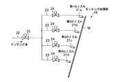
図2に示すように、第1乃至第4のノズル21a〜21dはそれぞれ主供給管22から分岐された4つの分岐管23に接続されている。各分岐管23には流量制御弁24が設けられている。それによって、第1乃至第4のノズル21a〜21dからはそれぞれの流量制御弁24の設定に基く流量で基板Wの表面に向けて処理液としてのエッチング液を噴射することができるようになっている。なお、上記主供給管22には開閉制御弁25が設けられ、この開閉制御弁25が開放されることで、エッチング液が各分岐管23に供給される。
As shown in FIG. 2, the first to
基板Wの搬送方向に沿うノズル間隔は、各ノズル21a〜21dから基板Wの板面に噴射されたエッチング液が基板Wの搬送速度に応じて基板Wの板面に沿って流れる領域がそれぞれ重ならないように設定される。
The nozzle spacing along the transport direction of the substrate W is such that the regions where the etchant sprayed from the
図4は基板Wの搬送速度が2000mm/min、4000mm/min及び6000mm/minのときに上記各高さ位置に配置された第1乃至第4のノズル21a〜21dから噴射されたエッチング液が基板Wの板面を流れる領域を実験によって求めたグラフである。同図において、曲線X1 〜X4 は基板Wの搬送速度が2000mm/min、曲線Y1 〜Y4 は4000mm/min、曲線Z1 〜Z4 は6000mm/minの場合である。
FIG. 4 shows that the etching liquid sprayed from the first to
たとえば、高さが1800mmの位置に配置された第1のノズル21aから噴射されるエッチング液は、基板Wの搬送速度が2000mm/minのときには、曲線X1 で示すように第1のノズル21aから噴射されたエッチング液は垂直方向下方から基板Wの搬送方向に約20mmずれた領域の範囲を流れる。搬送速度が4000mm/minのときには、曲線Y1 で示すように垂直方向下方から基板Wの搬送方向に約40mmずれた領域の範囲を流れる。搬送速度が6000mm/minのときには、曲線Z1 で示すように垂直方向下方から基板Wの搬送方向に約60mmずれた領域の範囲を流れる。
For example, etchant height is injected from the
図6乃至図8は、図4に示す実験に基いて、基板Wの搬送速度が2000mm/min、4000mm/min及び6000mm/minの場合に、第1乃至第4のノズル21a〜21dから噴射されて基板Wの板面を流れるエッチング液の領域がそれぞれ重ならないように、上記第1乃至第4のノズル21a〜21dの配置状態及び各ノズルから噴射されて基板Wの板面に沿って流れるエッチング液の領域を示している。
6 to 8 are ejected from the first to
図5において、曲線Aは第1乃至第4のノズル21a〜21dから基板Wの板面に噴射されて下方へ流れたエッチング液の基板Wの下端部における速度を示しており、曲線Bは各ノズル21a〜21dから基板Wの板面に噴射されたエッチング液が基板Wの下端部に到達するまでの時間を示している。
In FIG. 5, a curve A indicates the velocity at the lower end portion of the substrate W of the etching solution that is sprayed from the first to
このグラフから分かるように、基板Wの高い位置から噴射されたエッチング液は、低い位置から噴射されたエッチング液よりも、下端部に到達するまでの時間は長くなるが、基板Wの下端部での速度は低い位置から噴射されたエッチング液よりも速くなっていることが分かる。 As can be seen from this graph, the etchant sprayed from the high position of the substrate W takes longer to reach the lower end than the etchant sprayed from the lower position, but at the lower end of the substrate W. It can be seen that the speed is higher than that of the etchant sprayed from a low position.
たとえば、高さ900mmの位置の第3のノズル21cから噴射されたエッチング液が下端部に到達するまでの時間は0.44secであるから、高さが2倍の1800mmの位置にある第1のノズル21aから噴射されたエッチング液が下端部に到達するまでの計算上の時間はその2倍の0.88secであるが、実測値は0.62secであった。つまり、基板Wの下端部においては、高い位置から落下するエッチング液は低い位置から落下するエッチング液よりも加速度が大きくなるため、図5に示すような測定結果が得られる。
For example, since the time until the etching solution sprayed from the
上記純水洗浄部19は、上記エッチング処理部18でエッチングされた基板Wの板面を純水によって洗浄する。純水洗浄部19の構造の詳細は図示しないが、たとえば基板Wの搬送方向に対して所定の角度で傾斜して形成された複数のスリット状のノズルから基板Wの表裏両面の全体にわたって純水をほぼ均一に噴射できるようになっている。それによって、上記エッチング処理部18でエッチング処理されることで残留したエッチング液が上記純水洗浄部19を通過することで洗い流される。
The pure
上記乾燥処理部20は、上記純水洗浄部19で洗浄処理された基板Wに付着残留する純水を除去する。乾燥処理部20は不活性ガスなどの清浄な圧縮気体を比較的高い圧力で噴射するエアナイフから構成されており、搬送される基板Wの表裏両面に圧縮気体を噴射することで、上記純水洗浄部19で洗浄処理されることでその板面に付着残留した純水を除去するようになっている。
The drying
基板Wが乾燥処理部20で乾燥処理されると、この乾燥処理部20が設けられた回転ステーション9が180度回転し、乾燥処理した基板Wをアンローダ部3側に向ける。その状態で、基板Wはアンローダ部3に向かって搬送され、搬送手段10から上記アンローダ部3に受け渡される。
When the substrate W is dried by the drying
上記構成の処理装置によれば、基板Wが搬送手段10によって所定方向に搬送され、ブラシ洗浄部17で洗浄された後、エッチング処理部18に到達すると、ここで基板Wの表面はエッチング処理される。基板Wをエッチング処理する場合、エッチング処理部18の第1乃至第4のノズル21a〜21dは、図6乃至図8に示すように基板Wの高さ寸法と搬送速度に応じて配置されている。
According to the processing apparatus having the above configuration, when the substrate W is transported in the predetermined direction by the transport means 10 and cleaned by the
つまり、第1乃至第4のノズル21a〜21dからそれぞれ基板Wの板面に噴射されて下方に向かって流れる、エッチング液の各領域が重なることがないよう、上記第1乃至第4のノズル21a〜21dの間隔が基板Wの搬送速度に応じて設定されている。
That is, the first to
たとえば、基板Wが6000mm/sec搬送速度で搬送される場合、図8に示すように第1乃至第4のノズル21a〜21dから噴射されたエッチング液が下方に向かって流れる領域を、第1乃至第4の領域をR1 〜R4 とすると、これらの各領域R1 〜R4 は基板Wの上下方向全長にわたって隣り合う他の領域に重なり合うことがない。
For example, when the substrate W is transported at a transport speed of 6000 mm / sec, as shown in FIG. 8, the first to fourth regions in which the etching liquid sprayed from the first to
そのため、基板Wの第1の領域R1 をエッチングしたエッチング液は第2の領域R2 をエッチングしたエッチング液に混じり合うことがなく、同様に第3、第4の領域R3 、R4 をエッチング処理したエッチング液に他の領域をエッチング処理したエッチング液が混じり合うことがない。 Therefore, the first region R 1 and etched the etching solution of the substrate W without miscible in an etching solution to etch the second region R 2, likewise the third, the fourth region R 3, R 4 Etching solution that has been etched in other regions does not mix with the etched etching solution.
たとえば、第1の領域R1 をエッチング処理したエッチング液が第2の領域R2 をエッチング処理したエッチング液に混合すると、エッチング液の反応性が劣化するということがある。しかしながら、上述したように第1乃至第4のノズル21a〜21dから噴射されたエッチング液は混じり合うことなくそれぞれの領域R1 〜R4 を流れる。
For example, the etching solution in which the first region R 1 and the etching process is to mix the second region R 2 in the etching solution etching process, it may be referred reactive etchant is deteriorated. However, flow through each of the regions R 1 to R 4 without miscible first to etchant injected from the
そのため、基板Wは各ノズル21a〜21dから噴射されるエッチング液による領域R1 〜R4 が反応性が劣化していないエッチング液によってエッチング処理されるから、そのエッチング処理を基板Wの表面全体にわたって均一に行うことができる。
Therefore, the substrate W is etched by the etching solution in which the regions R 1 to R 4 by the etching solution sprayed from the
図8に示すように、基板Wの高さ方向を、第1乃至第4のノズル21a〜21dの配置高さに応じて第1乃至第4の高さ部分H1 〜H4 に分けると、第1の高さ部分H1 は第1の領域R1 を流れるエッチング液だけによってエッチングされるが、第2の高さ部分H2 は第1、第2の領域R1 、R2 を流れるエッチング液によってエッチングされる。同様に、第3の高さ部分H3 は第1乃至第3の領域R1 〜R3 を流れるエッチング液によってエッチングされ、第4の高さ部分H4 は第1乃至第4の領域を流れるエッチング液によってエッチングされる。
As shown in FIG. 8, when the height direction of the substrate W is divided into first to fourth height portions H 1 to H 4 according to the arrangement height of the first to
各高さ部分H1 〜H4 がエッチング液によってエッチングされる面積を図8に斜線で示す。第4の高さ部分H4 は第1乃至第4のノズル21a〜21dから噴射されたエッチング液によってエッチングされることになるから最大となり、その部分の面積を“1”とすると、第1のノズルからのエッチング液だけによってエッチングされる第1の高さ部分H1 の面積は0.016となる。同様に第2の高さ部分は0.125、第3の高さ部分は0.422となる。
The area where each of the height portions H 1 to H 4 is etched by the etching solution is shown by hatching in FIG. When the fourth height parts H 4 becomes maximum because to be etched by an etchant that is injected from the first to
第4の高さ部分H4 に流れるエッチング液の流量を“1”とすると、第1乃至第3の高さ部分H1 〜H3 には上述した面積比の逆数に応じた流量となるよう、各第1乃至第4のノズル21a〜21dから噴射されるエッチング液の流量を設定する。
When "1" the flow rate of the etchant flows to the fourth height parts H 4, the first to third height parts H 1 to H 3 to the flow rate corresponding to the inverse of the above-mentioned area ratio The flow rate of the etchant sprayed from each of the first to
たとえば、第4の高さ部分H4 と第1の高さ部分H1 との面積比は1:0.016であるから、流量比はその逆数である、1:62.5になるよう、第1のノズル21aからのエッチング液の供給量を設定する。同様に、第4の高さ部分H4 と第2の高さ部分H2 との流量比は1:8.0、第4の高さ部分H4 と第3の高さ部分H3 との流量比は1:2.4に設定する。
For example, since the area ratio of the fourth height portion H 4 and the first height portion H 1 is 1: 0.016, the flow rate ratio is the reciprocal, that is, 1: 62.5. The supply amount of the etching solution from the
このように、各ノズルからのエッチング液の供給量を面積比の逆数に応じて設定すれば、基板Wの各高さ部分がエッチング液から受ける単位時間当たりのエッチング処理量(処理面積×エッチング液量)はほぼ同じになるから、このことによっても基板Wの表面を全体にわたってほぼ均一にエッチング処理することができる。 Thus, if the supply amount of the etching solution from each nozzle is set according to the reciprocal of the area ratio, the etching processing amount per unit time that each height portion of the substrate W receives from the etching solution (processing area × etching solution) Therefore, the surface of the substrate W can be etched almost uniformly over the entire surface.
図9はこの発明の第2の実施の形態を示す。この実施の形態は、立位状態で搬送される基板Wの高さ方向に沿って複数のノズル、たとえば5つのノズル21が基板Wの上方から下方に沿って一列に配置されている。複数のノズル21は、基板Wの高さ方向上方から下方に行くにしたがって、これらノズル21のピッチP1 〜P4 が次第に大きくなるよう設定されている。
なお、ノズル21が接続された各分岐管23には第1の実施の形態と同様、流量制御弁24が設けられ、主供給管22には開閉制御弁25が設けられている。
FIG. 9 shows a second embodiment of the present invention. In this embodiment, a plurality of nozzles, for example, five
Each
ノズル21から基板Wの高さ方向上部に噴射供給されるエッチング液は、下部に噴射供給されるエッチング液よりも下方へ落下する速度が大きい。そのため、複数のノズル21を基板Wの高さ方向に沿って等間隔で配置したのでは、基板Wの上部が受ける単位時間当たりのエッチング処理量が下部よりも小さくなる。
The etching solution sprayed and supplied from the
しかしながら、上述したように複数のノズル21の配置ピッチを、基板Wの下部よりも上部で密にしたから、基板Wの高さ方向全長にわたって基板Wが受ける単位時間当たりのエッチング処理量をほぼ同じにすることができる。それによって、基板Wのエッチング処理を全体にわたって均一に行うことが可能となる。
However, since the arrangement pitch of the plurality of
図10はこの発明の第3の実施の形態を示す。この実施の形態は、立位状態で搬送される基板Wの高さ方向に沿って複数のノズル、たとえば4つのノズル21をほぼ等間隔で配置する。各ノズル21は、第1の実施の形態と同様、分岐管23を介して主供給管22に接続されている。
FIG. 10 shows a third embodiment of the present invention. In this embodiment, a plurality of nozzles, for example, four
各分岐管23にはそれぞれ圧力設定弁31が設けられ、その圧力設定弁31によって各ノズル21から噴射されるエッチング液の圧力を設定することができるようになっている。この実施の形態では、高さ方向上方に位置するノズル21に供給されるエッチング液の圧力が下方に位置するノズル21への供給圧量よりも高くなるよう設定されている。
Each
それによって、立位状態で搬送される基板Wの高さ方向上部には、下部よりも多くのエッチング液を供給することができるから、基板Wの高さ方向全長にわたってほぼ均一なエッチングを行うことが可能となる。 As a result, more etching solution can be supplied to the upper part in the height direction of the substrate W transported in the standing state than in the lower part, so that almost uniform etching is performed over the entire length in the height direction of the substrate W. Is possible.
図10に示す第3の実施の形態において、各分岐管23には圧力設定弁31に代わり流量調整弁を設けるようにしてもよい。それによって、各ノズル21から噴射されるエッチング液の流量を調整することができる。たとえば、各流量調整弁によって、高さ方向上方に位置するノズル21に供給されるエッチング液の量を下方に位置するノズル21へ供給される量よりも多くなるよう設定する。
In the third embodiment shown in FIG. 10, each
それによって、立位状態で搬送される基板Wの高さ方向上部には、下部に比べて多量のエッチング液を供給することができるから、基板Wの上部に供給されたエッチング液が下部に供給されたエッチング液よりも下方へ流れる速度が速くても、基板Wの高さ方向全長をほぼ均一にエッチングすることが可能となる。 Accordingly, a larger amount of etching solution can be supplied to the upper portion of the substrate W in the standing position than the lower portion, so that the etching solution supplied to the upper portion of the substrate W is supplied to the lower portion. Even if the velocity of flowing downward is higher than that of the etched etchant, the entire length in the height direction of the substrate W can be etched almost uniformly.
図11はこの発明の第4の実施の形態を示す。この実施の形態は第1の実施の形態と類似するが、基板Wに対して第1乃至第6の6つのノズル21a〜21fによって処理液を噴射供給するようにしている。
FIG. 11 shows a fourth embodiment of the present invention. Although this embodiment is similar to the first embodiment, the processing liquid is jetted and supplied to the substrate W by the first to
第1、第2のノズル21a,21bは第1のヘッダ管35aに設けられ、第3、第4のノズル21c,21dは第2のヘッダ管35bに設けられ、第5、第6のノズル21e,21fは第3のヘッダ管35cに設けられている。各ヘッダ管35a〜35cはそれぞれ流量制御弁24が設けられた分岐管23を介して開閉制御弁25が設けられた主供給管22に接続されている。
The first and
第1のヘッダ管35aが最上段に配置され、第2のヘッダ管35bが中段、第3のヘッダ管35cが下段に配置されている。それによって、第1のノズル21aが最も高い位置にあり、第2乃至第6のノズル21b〜21fが順次高さを低くして配置されている。さらに、第1乃至第6のノズル21a〜21fは、上記第1の実施の形態と同様、高さ方向上方に位置するノズルが下方に位置するノズルよりも基板Wの搬送方向後方に位置するよう配置されている。
The
このように、第1乃至第3の各ヘッダ管35a〜35cに2つのノズルを設けたことで、各ヘッダ管35a〜35cに設けられた2つのノズルの口径が同じであれば、処理液を同じ流量で噴射することができる。1つのヘッダ管に設けられた2つのノズルから噴射される処理液の流量を変えたい場合には、2つのノズルの口径を変えるようにすればよい。3つのヘッダ管35a〜35cに供給される処理液の流量は、各分岐管23に設けられた流量制御弁24によって調整することができる。
As described above, if the two nozzles provided in each of the
したがって、このような構成であっても、6つのノズル21a〜21fから噴射される処理液の量を、高さ方向上方に位置するノズルを下方に位置するノズルよりも大きくなるよう設定することが可能である。
Therefore, even in such a configuration, the amount of the processing liquid ejected from the six
図12と図13はこの発明の第5の実施の形態を示す。上記各実施の形態ではノズルとしてフラットタイプやコーンタイプなどの処理液の噴射断面積が円形状のノズルを例に挙げたが、この実施の形態では処理液を直線状に噴射するスリットタイプのノズルが用いられている。 12 and 13 show a fifth embodiment of the present invention. In each of the above embodiments, a nozzle having a circular cross section of the treatment liquid, such as a flat type or a cone type, is exemplified as a nozzle. However, in this embodiment, a slit type nozzle that jets the treatment liquid linearly. Is used.
この第5の実施の形態では、スリットタイプの第1乃至第5の5つのノズル121a〜121eが基板Wの高さ方向に所定間隔で、しかも高さ方向上方に位置するノズルが下方に位置するノズルよりも基板Wの搬送方向後方に位置するように配置されている。各ノズル121a〜121eは処理液の噴射方向を鉛直方向下方に向けて配置されている。
In the fifth embodiment, slit type first to
スリットタイプのノズル121a〜121eを用いることで、基板Wの全面に処理液を均一に、しかも迅速に噴射することが可能となるから、処理液による処理を板面全体にわたって均一に行なうことが可能となる。
By using the
また、スリットタイプのノズルは、処理液を霧状にして噴射しないため、ミストの発生が少ない。そのため、薬液処理後に純水を噴射する場合、純水のミストが基板Wの純水がまだ噴射されていない部分に付着し、薬液による反応が他の部分と相違するのを防止できる。その結果、基板W全体を薬液によって均一に処理することが可能となる。 In addition, since the slit type nozzle does not spray the treatment liquid in a mist state, the generation of mist is small. Therefore, when pure water is jetted after the chemical treatment, it is possible to prevent the mist of pure water from adhering to the portion of the substrate W where the pure water has not been jetted and causing the chemical reaction to differ from other portions. As a result, the entire substrate W can be uniformly processed with the chemical solution.
この実施の形態において、各ノズル121a〜121eへの処理液の供給は、第1の実施の形態と同様、主供給管22に開閉制御弁25を設け、この主供給管22から5つの分岐管23を分岐し、各分岐管23を、それぞれ流量制御弁24を介して各ノズル121a〜121eに接続して行なわれる。したがって、各ノズル121a〜121eへの処理液の供給量は、各流量制御弁24の開度を調整することで制御することができる。
In this embodiment, the supply of the processing liquid to each of the
図14はこの発明の第6の実施の形態を示す。この実施の形態はスリットタイプの5つのノズル121a〜121eを用いる点では第5の実施の形態と同じであるが、各ノズルはスリット面を所定の角度で傾斜して搬送される基板Wの板面に対してほぼ平行にして配置されている。つまり、処理液の噴射方向を基板Wの板面に対して直交する方向に向けて配置されているという点で第5の実施の形態と異なる。
FIG. 14 shows a sixth embodiment of the present invention. This embodiment is the same as the fifth embodiment in that five slit-
なお、この第6の実施の形態において、第1乃至第6のノズル121a〜121eは、上記第5の実施の形態と同様、高さ方向上方に位置するノズルが下方に位置するノズルよりも基板Wの搬送方向後方に位置するよう配置されている。
In the sixth embodiment, the first to
このような構成においても、第5の実施の形態と同様、基板Wの全面に処理液を均一に、しかも迅速に噴射することが可能となるから、処理液による処理を板面全体にわたって均一に行なうことが可能となる。 Even in such a configuration, since the processing liquid can be sprayed uniformly and rapidly over the entire surface of the substrate W, as in the fifth embodiment, the processing with the processing liquid can be performed uniformly over the entire plate surface. Can be performed.
図15と図16はこの発明の第7の実施の形態である。この第7の実施の形態は、図14に示す第6の実施の形態の変形例である。すなわち、ノズルにはスリットタイプの5つのノズル121a〜121eが用いられている。各ノズル121a〜121eは、基板Wの高さ方向に所定間隔で、しかも高さ方向上方に位置するノズルが下方に位置するノズルよりも基板Wの搬送方向後方に位置するように配置されている。
15 and 16 show a seventh embodiment of the present invention. The seventh embodiment is a modification of the sixth embodiment shown in FIG. That is, five
各ノズル121a〜121eは、図5に矢印で示すようにスリットから噴射される処理液が放物線Pを描くよう、噴射方向を上方に向けて配置されている。さらに、図16に示すように各ノズル121a〜121eは、スリットから噴射された処理液の放物線Pの頂点Tの部分が基板Wの板面に当たるように配置されている。
Each
このように、基板Wの板面に対して各ノズル121a〜121eを配置すると、処理液は基板Wの板面に流速が0に近い緩やかな状態で接触してその板面を下方へ流れる。そのため、処理液が基板Wの板面で跳ね返るのが防止される。
Thus, when each
たとえば、処理液として薬液などによって処理された基板を処理液としての純水でリンス処理するような場合、純水が基板Wの板面に強く当たって跳ね返ると、薬液を含む純水が基板Wのまだリンス処理され邸内部分に付着し、その部分が薬液が希釈されてその部分の反応が他の部分と相違し、基板Wの処理状態が不均一になることがある。 For example, in a case where a substrate treated with a chemical solution or the like as a treatment liquid is rinsed with pure water as a treatment liquid, if the pure water strongly hits the plate surface of the substrate W and bounces, the pure water containing the chemical solution is transferred to the substrate W. However, the substrate is still rinsed and adhered to the inside of the residence, and the chemical solution is diluted in the portion, the reaction of the portion is different from the other portions, and the processing state of the substrate W may become uneven.
しかしながら、各ノズル121a〜121eからリンス液を放物線状に噴射し、その放物線の頂点Tの部分を基板Wの板面に接触させるようにしたことで、リンス液が基板Wの板面で跳ね返るということがほとんどない。そのため、薬液を含むリンス液が基板Wのすでにリンス処理された部分に付着して反応するということがないから、リンス処理時に基板Wの処理状態にむらが生じるのを防止できる。
However, the rinse liquid is sprayed in a parabolic shape from each of the
なお、この第7の実施の形態において、処理液としてはリンス液に限られず、薬液であってもよい。薬液を用いた場合、リンス液を用いた場合と同様、薬液が基板Wの板面で跳ね返って他の部分に付着することがないから、薬液による基板Wの処理が不均一になるのを防止できる。
また、ノズルとしてはスリットタイプに限られず、フラットタイプやコーンタイプなど他のタイプのノズルであってもよい。
In the seventh embodiment, the treatment liquid is not limited to the rinse liquid, and may be a chemical liquid. When the chemical solution is used, the chemical solution does not rebound on the plate surface of the substrate W and adheres to other parts as in the case of using the rinse solution, so that the processing of the substrate W by the chemical solution is prevented from becoming non-uniform. it can.
Further, the nozzle is not limited to the slit type, and may be another type of nozzle such as a flat type or a cone type.
この発明は上記各実施の形態に限定されず、要旨を逸脱しない範囲で種々変形可能である。たとえば、処理部において基板に供給される処理液としてはエッチング液に限定されず、基板を処理する他の薬液、たとえば現像液、剥離液、過酸化水素水、アンモニア水などであってもよい。また、この発明は、純水洗浄部にも適用することが可能であり、その場合ノズルから純水を供給することで、基板のリンス処理を全面にわたって均一に行うことができる。 The present invention is not limited to the above embodiments, and various modifications can be made without departing from the scope of the invention. For example, the processing solution supplied to the substrate in the processing unit is not limited to the etching solution, and may be other chemicals for processing the substrate, such as a developing solution, a stripping solution, hydrogen peroxide solution, and aqueous ammonia. The present invention can also be applied to a pure water cleaning unit. In this case, by supplying pure water from a nozzle, the substrate can be uniformly rinsed over the entire surface.
10…搬送手段、18…エッチング処理部、19…純水洗浄部、20乾燥処理部、21a〜21d…ノズル、W…基板。
DESCRIPTION OF
Claims (3)
上記基板を立位状態で所定方向に搬送する搬送手段と、
この搬送手段によって立位状態で搬送される基板に処理液を噴射する処理部とを有し、
上記処理部は、上記基板の板面に処理液を噴射する複数のノズルを有し、これら複数のノズルは上記基板の高さ方向に所定間隔で、かつ高さ方向上方に位置するノズルが下方に位置するノズルよりも上記基板の搬送方向後方に位置するよう配置され、
上記基板の搬送方向において隣り合うノズルは、それぞれのノズルから噴射されて基板の板面に沿って流れる処理液の領域が重ならない間隔に設定されているとともに、高さ方向上方に位置するノズルは、下方に位置するノズルよりも、処理液の噴射量が大きく設定されることを特徴とする基板の処理装置。 In a processing apparatus for processing a substrate with a processing liquid,
Conveying means for conveying the substrate in a predetermined direction in a standing position;
A processing unit for injecting the processing liquid onto the substrate transported in a standing state by the transporting means,
The processing unit has a plurality of nozzles for injecting a processing liquid onto the plate surface of the substrate, and the plurality of nozzles are arranged at predetermined intervals in the height direction of the substrate and the nozzles located above the height direction are below It is arranged so as to be located behind the nozzle in the transport direction of the substrate ,
The nozzles adjacent to each other in the substrate transport direction are set at an interval where the regions of the processing liquid ejected from the respective nozzles and flowing along the plate surface of the substrate do not overlap, and the nozzles located above the height direction are An apparatus for processing a substrate, characterized in that the injection amount of the processing liquid is set larger than that of the nozzle located below .
上記基板を立位状態で所定方向に搬送する搬送工程と、
高さ方向上方に位置するノズルを下方に位置するノズルよりも上記基板の搬送方向後方に位置させ、高さ方向上方に位置するノズルから噴射される処理液の噴射量を、下方に位置するノズルよりも大きく設定して立位状態で搬送される基板に複数のノズルから処理液を噴射するとともに、各ノズルから噴射されて基板の板面に沿って流れ落ちるそれぞれの処理液の領域が重ならないようにする噴射工程と
を具備したことを特徴とする基板の処理方法。 In the processing method of arranging a plurality of nozzles along the height direction of the substrate and processing the substrate by spraying a processing liquid from these nozzles,
A transporting step of transporting the substrate in a predetermined direction in a standing position;
The nozzle located above the height direction is positioned behind the nozzle located below the substrate in the transport direction of the substrate, and the amount of processing liquid sprayed from the nozzle located above the height direction is set below the nozzle. The processing liquid is sprayed from a plurality of nozzles onto a substrate that is set larger than the substrate and is transported in a standing position, and the regions of the processing liquid sprayed from the nozzles and flowing down along the plate surface of the substrate do not overlap. A substrate processing method comprising: an injection step.
Priority Applications (4)
| Application Number | Priority Date | Filing Date | Title |
|---|---|---|---|
| JP2004191134A JP4421956B2 (en) | 2003-07-18 | 2004-06-29 | Substrate processing apparatus and processing method |
| TW093120984A TWI347629B (en) | 2003-07-18 | 2004-07-14 | Apparatus for treating substrates and method of treating substrates |
| CNB2004100640625A CN100419501C (en) | 2003-07-18 | 2004-07-16 | Apparatus and method for processing substrate |
| KR1020040055566A KR101055247B1 (en) | 2003-07-18 | 2004-07-16 | Substrate processing apparatus and processing method |
Applications Claiming Priority (2)
| Application Number | Priority Date | Filing Date | Title |
|---|---|---|---|
| JP2003199087 | 2003-07-18 | ||
| JP2004191134A JP4421956B2 (en) | 2003-07-18 | 2004-06-29 | Substrate processing apparatus and processing method |
Related Child Applications (1)
| Application Number | Title | Priority Date | Filing Date |
|---|---|---|---|
| JP2009254142A Division JP5352426B2 (en) | 2003-07-18 | 2009-11-05 | Substrate processing equipment |
Publications (2)
| Publication Number | Publication Date |
|---|---|
| JP2005052825A JP2005052825A (en) | 2005-03-03 |
| JP4421956B2 true JP4421956B2 (en) | 2010-02-24 |
Family
ID=34379735
Family Applications (1)
| Application Number | Title | Priority Date | Filing Date |
|---|---|---|---|
| JP2004191134A Expired - Fee Related JP4421956B2 (en) | 2003-07-18 | 2004-06-29 | Substrate processing apparatus and processing method |
Country Status (4)
| Country | Link |
|---|---|
| JP (1) | JP4421956B2 (en) |
| KR (1) | KR101055247B1 (en) |
| CN (1) | CN100419501C (en) |
| TW (1) | TWI347629B (en) |
Families Citing this family (19)
| Publication number | Priority date | Publication date | Assignee | Title |
|---|---|---|---|---|
| JP4627681B2 (en) * | 2005-04-20 | 2011-02-09 | 芝浦メカトロニクス株式会社 | Substrate processing apparatus and processing method |
| JP4557872B2 (en) * | 2005-11-28 | 2010-10-06 | 株式会社日立ハイテクノロジーズ | Substrate processing apparatus, substrate processing method, and substrate manufacturing method |
| TWI319213B (en) * | 2005-11-28 | 2010-01-01 | Hitachi High Tech Corp | A substrate processing device, a substrate processing method and a production method for a substrate |
| JP4685618B2 (en) * | 2005-12-13 | 2011-05-18 | 芝浦メカトロニクス株式会社 | Substrate processing equipment |
| KR100835745B1 (en) * | 2006-12-29 | 2008-06-09 | 최찬규 | Top down glass thinning method |
| JP2008277556A (en) * | 2007-04-27 | 2008-11-13 | Shibaura Mechatronics Corp | Processing apparatus for substrate |
| JP4575932B2 (en) * | 2007-05-29 | 2010-11-04 | 化研テック株式会社 | Pallet cleaning device and pallet cleaning method |
| KR100865475B1 (en) * | 2007-08-30 | 2008-10-27 | 세메스 주식회사 | Nozzle assembly, processing liquid supply apparatus having the same, and processing liquid supply method using the same |
| JP5362623B2 (en) * | 2010-03-03 | 2013-12-11 | 大日本スクリーン製造株式会社 | Substrate processing equipment |
| DE102010013909A1 (en) * | 2010-04-01 | 2011-10-06 | Lp Vermarktungs Gmbh & Co. Kg | Apparatus and method for spraying a surface of a substrate |
| CN102094199A (en) * | 2010-11-23 | 2011-06-15 | 黄佳佳 | Etching equipment of electronic soft label |
| US8458842B2 (en) * | 2011-05-10 | 2013-06-11 | Nanya Technology Corp. | Post-CMP wafer cleaning apparatus |
| KR101342616B1 (en) * | 2013-04-26 | 2013-12-20 | 창성 주식회사 | Vertical substrate detachment system |
| KR102223764B1 (en) * | 2013-12-27 | 2021-03-05 | 세메스 주식회사 | Apparatus and Method for treating substrate |
| CN105158829B (en) | 2015-07-30 | 2019-06-04 | 京东方科技集团股份有限公司 | Substrate, color filter module, method for forming substrate module, and display device |
| JP6667241B2 (en) * | 2015-09-28 | 2020-03-18 | 株式会社Screenホールディングス | Processing liquid supply device, substrate processing system and processing liquid supply method |
| CN106992136B (en) * | 2017-04-20 | 2020-04-07 | 武汉华星光电技术有限公司 | Wet etching equipment and wet etching method |
| KR102433317B1 (en) * | 2017-10-11 | 2022-08-17 | 삼성디스플레이 주식회사 | Apparatus for wet etchng |
| CN111006262A (en) * | 2019-12-31 | 2020-04-14 | 美埃(中国)环境净化有限公司 | Washing type oil fume removal purification device and washing control method thereof |
Family Cites Families (8)
| Publication number | Priority date | Publication date | Assignee | Title |
|---|---|---|---|---|
| JPH10118583A (en) | 1996-10-24 | 1998-05-12 | Nippon Electric Glass Co Ltd | Cleaning device for planar matter |
| JP3550277B2 (en) * | 1997-07-24 | 2004-08-04 | 大日本スクリーン製造株式会社 | Substrate processing equipment |
| KR100343044B1 (en) * | 1997-08-28 | 2002-10-25 | 다이닛뽕스크린 세이조오 가부시키가이샤 | Substrate Processing Equipment and Processing Method |
| JP3556110B2 (en) * | 1998-12-22 | 2004-08-18 | 大日本スクリーン製造株式会社 | Substrate processing equipment |
| JP2001343632A (en) * | 2000-06-02 | 2001-12-14 | Sharp Corp | Method for manufacturing liquid crystal display device |
| JP3622842B2 (en) * | 2000-12-11 | 2005-02-23 | 住友精密工業株式会社 | Transport type substrate processing equipment |
| WO2002049087A1 (en) * | 2000-12-12 | 2002-06-20 | Sumitomo Precision Products Co., Ltd | Oscillating shower transfer type substrate treatment device |
| JP4180250B2 (en) * | 2001-05-30 | 2008-11-12 | 東京エレクトロン株式会社 | Substrate processing apparatus and substrate processing method |
-
2004
- 2004-06-29 JP JP2004191134A patent/JP4421956B2/en not_active Expired - Fee Related
- 2004-07-14 TW TW093120984A patent/TWI347629B/en not_active IP Right Cessation
- 2004-07-16 CN CNB2004100640625A patent/CN100419501C/en not_active Expired - Fee Related
- 2004-07-16 KR KR1020040055566A patent/KR101055247B1/en active IP Right Grant
Also Published As
| Publication number | Publication date |
|---|---|
| JP2005052825A (en) | 2005-03-03 |
| CN1576961A (en) | 2005-02-09 |
| TWI347629B (en) | 2011-08-21 |
| KR101055247B1 (en) | 2011-08-08 |
| CN100419501C (en) | 2008-09-17 |
| KR20050009695A (en) | 2005-01-25 |
| TW200507038A (en) | 2005-02-16 |
Similar Documents
| Publication | Publication Date | Title |
|---|---|---|
| JP4421956B2 (en) | Substrate processing apparatus and processing method | |
| KR101408757B1 (en) | The substrate processing apparatus | |
| JP4641964B2 (en) | Substrate processing apparatus and substrate processing method | |
| KR100981212B1 (en) | Liquid treatment method and liquid treatment device | |
| US20050139240A1 (en) | Rinsing and drying apparatus having rotatable nozzles and methods of rinsing and drying semiconductor wafers using the same | |
| KR101335885B1 (en) | Substrate processing apparatus with a non-contact floating transfer system | |
| CN101219427A (en) | Substrate processing device | |
| US20010006072A1 (en) | Ultrasonic processing device and electronic parts fabrication method using the same | |
| TWI443734B (en) | Substrate processing device | |
| JP5352426B2 (en) | Substrate processing equipment | |
| JP2008023489A (en) | Substrate processing apparatus | |
| KR101204725B1 (en) | Apparatus for treating substrates | |
| KR101149455B1 (en) | Substrate processing equipment, substrate carrying equipment and substrate processing method | |
| CN111580355A (en) | Liquid treatment apparatus and liquid treatment method | |
| JP2021022629A (en) | Etching device | |
| JP2004210511A (en) | Device and method for processing substrate | |
| KR100929577B1 (en) | Roller unit and substrate processing apparatus including the same | |
| JP2005244130A (en) | Method and apparatus for processing substrate | |
| JP5202400B2 (en) | Substrate processing apparatus and substrate processing method | |
| KR20100055812A (en) | Apparatus for processing a substrate | |
| KR102379013B1 (en) | Liquid treatment module, apparatus and method for treating a substrate with the same | |
| KR102278080B1 (en) | Substrate processing apparatus and substrate processing method | |
| TWI345260B (en) | Resist elimination device | |
| JP4892543B2 (en) | Substrate processing equipment | |
| JP2006289240A (en) | Treatment apparatus and treatment method of substrate |
Legal Events
| Date | Code | Title | Description |
|---|---|---|---|
| A621 | Written request for application examination |
Free format text: JAPANESE INTERMEDIATE CODE: A621 Effective date: 20070619 |
|
| A977 | Report on retrieval |
Free format text: JAPANESE INTERMEDIATE CODE: A971007 Effective date: 20090901 |
|
| A131 | Notification of reasons for refusal |
Free format text: JAPANESE INTERMEDIATE CODE: A131 Effective date: 20090908 |
|
| A521 | Request for written amendment filed |
Free format text: JAPANESE INTERMEDIATE CODE: A523 Effective date: 20091105 |
|
| TRDD | Decision of grant or rejection written | ||
| A01 | Written decision to grant a patent or to grant a registration (utility model) |
Free format text: JAPANESE INTERMEDIATE CODE: A01 Effective date: 20091201 |
|
| A01 | Written decision to grant a patent or to grant a registration (utility model) |
Free format text: JAPANESE INTERMEDIATE CODE: A01 |
|
| A61 | First payment of annual fees (during grant procedure) |
Free format text: JAPANESE INTERMEDIATE CODE: A61 Effective date: 20091203 |
|
| FPAY | Renewal fee payment (event date is renewal date of database) |
Free format text: PAYMENT UNTIL: 20121211 Year of fee payment: 3 |
|
| R150 | Certificate of patent or registration of utility model |
Ref document number: 4421956 Country of ref document: JP Free format text: JAPANESE INTERMEDIATE CODE: R150 Free format text: JAPANESE INTERMEDIATE CODE: R150 |
|
| FPAY | Renewal fee payment (event date is renewal date of database) |
Free format text: PAYMENT UNTIL: 20121211 Year of fee payment: 3 |
|
| FPAY | Renewal fee payment (event date is renewal date of database) |
Free format text: PAYMENT UNTIL: 20131211 Year of fee payment: 4 |
|
| LAPS | Cancellation because of no payment of annual fees |