JP4397856B2 - Vehicle lamp and vehicle lamp system - Google Patents
Vehicle lamp and vehicle lamp system Download PDFInfo
- Publication number
- JP4397856B2 JP4397856B2 JP2005165937A JP2005165937A JP4397856B2 JP 4397856 B2 JP4397856 B2 JP 4397856B2 JP 2005165937 A JP2005165937 A JP 2005165937A JP 2005165937 A JP2005165937 A JP 2005165937A JP 4397856 B2 JP4397856 B2 JP 4397856B2
- Authority
- JP
- Japan
- Prior art keywords
- lamp
- light emitting
- emitting element
- temperature
- vehicle
- Prior art date
- Legal status (The legal status is an assumption and is not a legal conclusion. Google has not performed a legal analysis and makes no representation as to the accuracy of the status listed.)
- Expired - Fee Related
Links
Images


Classifications
-
- F—MECHANICAL ENGINEERING; LIGHTING; HEATING; WEAPONS; BLASTING
- F21—LIGHTING
- F21V—FUNCTIONAL FEATURES OR DETAILS OF LIGHTING DEVICES OR SYSTEMS THEREOF; STRUCTURAL COMBINATIONS OF LIGHTING DEVICES WITH OTHER ARTICLES, NOT OTHERWISE PROVIDED FOR
- F21V29/00—Protecting lighting devices from thermal damage; Cooling or heating arrangements specially adapted for lighting devices or systems
- F21V29/50—Cooling arrangements
- F21V29/70—Cooling arrangements characterised by passive heat-dissipating elements, e.g. heat-sinks
- F21V29/74—Cooling arrangements characterised by passive heat-dissipating elements, e.g. heat-sinks with fins or blades
- F21V29/76—Cooling arrangements characterised by passive heat-dissipating elements, e.g. heat-sinks with fins or blades with essentially identical parallel planar fins or blades, e.g. with comb-like cross-section
-
- B—PERFORMING OPERATIONS; TRANSPORTING
- B60—VEHICLES IN GENERAL
- B60Q—ARRANGEMENT OF SIGNALLING OR LIGHTING DEVICES, THE MOUNTING OR SUPPORTING THEREOF OR CIRCUITS THEREFOR, FOR VEHICLES IN GENERAL
- B60Q1/00—Arrangement of optical signalling or lighting devices, the mounting or supporting thereof or circuits therefor
- B60Q1/0017—Devices integrating an element dedicated to another function
- B60Q1/0023—Devices integrating an element dedicated to another function the element being a sensor, e.g. distance sensor, camera
-
- B—PERFORMING OPERATIONS; TRANSPORTING
- B60—VEHICLES IN GENERAL
- B60Q—ARRANGEMENT OF SIGNALLING OR LIGHTING DEVICES, THE MOUNTING OR SUPPORTING THEREOF OR CIRCUITS THEREFOR, FOR VEHICLES IN GENERAL
- B60Q1/00—Arrangement of optical signalling or lighting devices, the mounting or supporting thereof or circuits therefor
- B60Q1/0029—Spatial arrangement
- B60Q1/0041—Spatial arrangement of several lamps in relation to each other
-
- F—MECHANICAL ENGINEERING; LIGHTING; HEATING; WEAPONS; BLASTING
- F21—LIGHTING
- F21S—NON-PORTABLE LIGHTING DEVICES; SYSTEMS THEREOF; VEHICLE LIGHTING DEVICES SPECIALLY ADAPTED FOR VEHICLE EXTERIORS
- F21S41/00—Illuminating devices specially adapted for vehicle exteriors, e.g. headlamps
- F21S41/10—Illuminating devices specially adapted for vehicle exteriors, e.g. headlamps characterised by the light source
- F21S41/14—Illuminating devices specially adapted for vehicle exteriors, e.g. headlamps characterised by the light source characterised by the type of light source
- F21S41/141—Light emitting diodes [LED]
- F21S41/147—Light emitting diodes [LED] the main emission direction of the LED being angled to the optical axis of the illuminating device
- F21S41/148—Light emitting diodes [LED] the main emission direction of the LED being angled to the optical axis of the illuminating device the main emission direction of the LED being perpendicular to the optical axis
-
- F—MECHANICAL ENGINEERING; LIGHTING; HEATING; WEAPONS; BLASTING
- F21—LIGHTING
- F21S—NON-PORTABLE LIGHTING DEVICES; SYSTEMS THEREOF; VEHICLE LIGHTING DEVICES SPECIALLY ADAPTED FOR VEHICLE EXTERIORS
- F21S41/00—Illuminating devices specially adapted for vehicle exteriors, e.g. headlamps
- F21S41/10—Illuminating devices specially adapted for vehicle exteriors, e.g. headlamps characterised by the light source
- F21S41/14—Illuminating devices specially adapted for vehicle exteriors, e.g. headlamps characterised by the light source characterised by the type of light source
- F21S41/141—Light emitting diodes [LED]
- F21S41/151—Light emitting diodes [LED] arranged in one or more lines
-
- F—MECHANICAL ENGINEERING; LIGHTING; HEATING; WEAPONS; BLASTING
- F21—LIGHTING
- F21S—NON-PORTABLE LIGHTING DEVICES; SYSTEMS THEREOF; VEHICLE LIGHTING DEVICES SPECIALLY ADAPTED FOR VEHICLE EXTERIORS
- F21S41/00—Illuminating devices specially adapted for vehicle exteriors, e.g. headlamps
- F21S41/10—Illuminating devices specially adapted for vehicle exteriors, e.g. headlamps characterised by the light source
- F21S41/14—Illuminating devices specially adapted for vehicle exteriors, e.g. headlamps characterised by the light source characterised by the type of light source
- F21S41/141—Light emitting diodes [LED]
- F21S41/155—Surface emitters, e.g. organic light emitting diodes [OLED]
-
- F—MECHANICAL ENGINEERING; LIGHTING; HEATING; WEAPONS; BLASTING
- F21—LIGHTING
- F21S—NON-PORTABLE LIGHTING DEVICES; SYSTEMS THEREOF; VEHICLE LIGHTING DEVICES SPECIALLY ADAPTED FOR VEHICLE EXTERIORS
- F21S43/00—Signalling devices specially adapted for vehicle exteriors, e.g. brake lamps, direction indicator lights or reversing lights
- F21S43/50—Signalling devices specially adapted for vehicle exteriors, e.g. brake lamps, direction indicator lights or reversing lights characterised by aesthetic components not otherwise provided for, e.g. decorative trim, partition walls or covers
-
- F—MECHANICAL ENGINEERING; LIGHTING; HEATING; WEAPONS; BLASTING
- F21—LIGHTING
- F21V—FUNCTIONAL FEATURES OR DETAILS OF LIGHTING DEVICES OR SYSTEMS THEREOF; STRUCTURAL COMBINATIONS OF LIGHTING DEVICES WITH OTHER ARTICLES, NOT OTHERWISE PROVIDED FOR
- F21V29/00—Protecting lighting devices from thermal damage; Cooling or heating arrangements specially adapted for lighting devices or systems
- F21V29/50—Cooling arrangements
- F21V29/70—Cooling arrangements characterised by passive heat-dissipating elements, e.g. heat-sinks
- F21V29/74—Cooling arrangements characterised by passive heat-dissipating elements, e.g. heat-sinks with fins or blades
- F21V29/76—Cooling arrangements characterised by passive heat-dissipating elements, e.g. heat-sinks with fins or blades with essentially identical parallel planar fins or blades, e.g. with comb-like cross-section
- F21V29/763—Cooling arrangements characterised by passive heat-dissipating elements, e.g. heat-sinks with fins or blades with essentially identical parallel planar fins or blades, e.g. with comb-like cross-section the planes containing the fins or blades having the direction of the light emitting axis
-
- F—MECHANICAL ENGINEERING; LIGHTING; HEATING; WEAPONS; BLASTING
- F21—LIGHTING
- F21S—NON-PORTABLE LIGHTING DEVICES; SYSTEMS THEREOF; VEHICLE LIGHTING DEVICES SPECIALLY ADAPTED FOR VEHICLE EXTERIORS
- F21S45/00—Arrangements within vehicle lighting devices specially adapted for vehicle exteriors, for purposes other than emission or distribution of light
- F21S45/40—Cooling of lighting devices
- F21S45/47—Passive cooling, e.g. using fins, thermal conductive elements or openings
-
- F—MECHANICAL ENGINEERING; LIGHTING; HEATING; WEAPONS; BLASTING
- F21—LIGHTING
- F21Y—INDEXING SCHEME ASSOCIATED WITH SUBCLASSES F21K, F21L, F21S and F21V, RELATING TO THE FORM OR THE KIND OF THE LIGHT SOURCES OR OF THE COLOUR OF THE LIGHT EMITTED
- F21Y2115/00—Light-generating elements of semiconductor light sources
- F21Y2115/10—Light-emitting diodes [LED]
Landscapes
- Engineering & Computer Science (AREA)
- General Engineering & Computer Science (AREA)
- Physics & Mathematics (AREA)
- Microelectronics & Electronic Packaging (AREA)
- Optics & Photonics (AREA)
- Mechanical Engineering (AREA)
- Lighting Device Outwards From Vehicle And Optical Signal (AREA)
- Non-Portable Lighting Devices Or Systems Thereof (AREA)
- Arrangement Of Elements, Cooling, Sealing, Or The Like Of Lighting Devices (AREA)
Description
本願発明は、発光素子を光源とする複数の灯具ユニットを備えてなる車両用灯具および車両用灯具システムに関するものである。 The present invention relates to a vehicular lamp and a vehicular lamp system including a plurality of lamp units each having a light emitting element as a light source.
ヘッドランプ等の車両用灯具においては、複数の灯具ユニットを備えた構成となっているが、近年の車両用灯具においては、各灯具ユニットの光源として発光ダイオード等の発光素子を用いたものも多く採用されてきている。 A vehicular lamp such as a headlamp has a configuration including a plurality of lamp units. However, in recent years, many vehicular lamps use a light emitting element such as a light emitting diode as a light source of each lamp unit. Has been adopted.
そして「特許文献1」には、発光素子を光源とする複数の灯具ユニットを備えてなる車両用灯具において、これら複数の灯具ユニットが共通の金属製支持部材に支持されたものが記載されている。 “Patent Document 1” describes a vehicular lamp including a plurality of lamp units each having a light emitting element as a light source, in which the plurality of lamp units are supported by a common metal support member. .
上記「特許文献1」に記載されているように、複数の灯具ユニットが共通の金属製支持部材に支持された構成とすれば、各灯具ユニットの発光素子で発生した熱を、熱伝導作用により、大きな熱容量を有する金属製支持部材に移動させることができ、これにより発光素子の温度上昇を抑制することができる。 As described in “Patent Document 1”, if a plurality of lamp units are supported by a common metal support member, the heat generated in the light-emitting elements of the lamp units is caused by heat conduction. It can be moved to a metal support member having a large heat capacity, whereby the temperature rise of the light emitting element can be suppressed.
しかしながら、複数の灯具ユニットとして、発光素子の発熱量が異なる灯具ユニットを備えている場合には、上記「特許文献1」に記載されているような金属製支持部材による放熱を図ったとしても、灯具ユニットによっては発光素子の温度が十分に下がり切らない事態も生じ得る。そして、このように温度が上昇したままの状態の発光素子においては、その光源光束が減少したり発光色が変化してしまう、という問題がある。 However, in the case where a plurality of lamp units are provided with lamp units having different amounts of heat generated by light emitting elements, even if heat dissipation by a metal support member as described in the above-mentioned "Patent Document 1" is attempted, Depending on the lamp unit, the temperature of the light emitting element may not be sufficiently lowered. In such a light emitting element in which the temperature remains elevated, there is a problem that the light source luminous flux decreases or the emission color changes.
本願発明は、このような事情に鑑みてなされたものであって、発光素子を光源とする複数の灯具ユニットを備えてなる車両用灯具において、各灯具ユニットの発光素子の温度上昇を抑制することができる車両用灯具および車両用灯具システムを提供することを目的とするものである。 The present invention has been made in view of such circumstances, and in a vehicular lamp including a plurality of lamp units each having a light emitting element as a light source, the temperature rise of the light emitting element of each lamp unit is suppressed. An object of the present invention is to provide a vehicular lamp and a vehicular lamp system that can be used.
本願発明は、複数の灯具ユニットが共通の金属製支持部材に支持されてなる構成とした上で、各灯具ユニットの配置に工夫を施すことにより、上記目的達成を図るようにしたものである。 In the present invention, a plurality of lamp units are supported by a common metal support member, and the above object is achieved by devising the arrangement of the lamp units.
すなわち、本願発明に係る車両用灯具は、
ランプボディと、このランプボディの前端開口部に取り付けられた透光カバーとで形成される灯室内に、発光素子を光源とする複数の灯具ユニットが収容されてなる車両用灯具において、
上記複数の灯具ユニットが、共通の金属製支持部材に支持されており、
上記複数の灯具ユニットとして、上記発光素子の発熱量が異なる第1および第2灯具ユニットを備えており、
上記第1および第2灯具ユニットが、上下方向に隣接して配置されており、
上記第1および第2灯具ユニットのうち、上記発熱量が相対的に大きい第1灯具ユニットが、上記発熱量が相対的に小さい第2灯具ユニットの下方側に配置されている、ことを特徴とするものである。
That is, the vehicular lamp according to the present invention is
In a vehicle lamp in which a plurality of lamp units each having a light emitting element as a light source are housed in a lamp chamber formed by a lamp body and a translucent cover attached to a front end opening of the lamp body,
The plurality of lamp units are supported by a common metal support member,
As the plurality of lamp units, the first and second lamp units having different heat generation amounts of the light emitting elements are provided,
The first and second lamp units are arranged adjacent to each other in the vertical direction,
Of the first and second lamp units, the first lamp unit having a relatively large calorific value is disposed below the second lamp unit having a relatively small calorific value. To do.
上記「車両用灯具」の種類は特に限定されるものではなく、例えば、ヘッドランプ、フォグランプ、コーナリングランプ、テールランプ、ストップランプ、バックアップランプ、ターンシグナルランプ、デイタイムランニングランプ等が採用可能である。 The type of the “vehicle lamp” is not particularly limited. For example, a head lamp, a fog lamp, a cornering lamp, a tail lamp, a stop lamp, a backup lamp, a turn signal lamp, a daytime running lamp, and the like can be employed.
上記「発光素子」の種類は特に限定されるものではなく、例えば、発光ダイオードやレーザダイオード等が採用可能である。また、この「発光素子」の具体的構成は特に限定されるものではなく、例えば、単一の発光チップが実装されたものであってもよいし、複数の発光チップが実装されたものであってもよい。 The type of the “light emitting element” is not particularly limited, and for example, a light emitting diode or a laser diode can be employed. Further, the specific configuration of the “light emitting element” is not particularly limited, and for example, a single light emitting chip may be mounted, or a plurality of light emitting chips may be mounted. May be.
上記「金属製支持部材」は、複数の灯具ユニットを支持する金属製の部材であれば、その具体的構成は特に限定されるものではない。ここでいう「金属製」には、1種類の金属からなるもののほか、2種類以上の金属からなる合金製のものも含まれる。また、この金属製支持部材は、ランプボディ等に対して傾動可能に支持されたものであってもよいし固定支持されたものであってもよい。 The “metal support member” is not particularly limited as long as it is a metal member that supports a plurality of lamp units. In this case, “made of metal” includes not only one made of metal but also an alloy made of two or more metals. The metal support member may be supported so as to be tiltable with respect to the lamp body or the like, or may be fixedly supported.
上記「複数の灯具ユニット」は、第1および第2灯具ユニットのみからなる構成であってもよいし、第1および第2灯具ユニット以外の灯具ユニットを備えた構成であってもよい。後者の場合には、その第1および第2灯具ユニットが、互いに発熱量が異なる発光素子を有する灯具ユニットで構成されていれば、その他の灯具ユニットの具体的構成については特に限定されるものではない。 The “plurality of lamp units” may include only the first and second lamp units, or may include a lamp unit other than the first and second lamp units. In the latter case, the specific configuration of the other lamp units is not particularly limited as long as the first and second lamp units are configured by lamp units having light emitting elements with different calorific values. Absent.
上記「第1および第2灯具ユニット」は、上下方向に隣接して配置されていれば、同一鉛直線上に配置されていなくてもよい。 The “first and second lamp units” may not be arranged on the same vertical line as long as they are arranged adjacent to each other in the vertical direction.
上記構成に示すように、本願発明に係る車両用灯具は、発光素子を光源とする複数の灯具ユニットを備えた構成となっているが、これら複数の灯具ユニットは共通の金属製支持部材に支持されているので、これら各灯具ユニットの点灯によりその発光素子が発熱しても、この熱は、熱伝導作用により、大きな熱容量を有する金属製支持部材に移動し、これにより各発光素子の温度上昇が抑制されることとなる。 As shown in the above configuration, the vehicular lamp according to the present invention includes a plurality of lamp units each having a light emitting element as a light source, and the plurality of lamp units are supported by a common metal support member. Therefore, even if the light emitting elements generate heat due to the lighting of each of these lamp units, this heat is transferred to a metal support member having a large heat capacity due to the heat conduction action, thereby increasing the temperature of each light emitting element. Will be suppressed.
その際、本願発明に係る車両用灯具においては、その複数の灯具ユニットとして、発光素子の発熱量が異なる第1および第2灯具ユニットを備えており、そして、これら第1および第2灯具ユニットは上下方向に隣接して配置されているが、これら第1および第2灯具ユニットのうち、発光素子の発熱量が相対的に大きい第1灯具ユニットは、発光素子の発熱量が相対的に小さい第2灯具ユニットの下方側に配置されているので、次のような作用効果を得ることができる。 In that case, in the vehicular lamp according to the present invention, as the plurality of lamp units, the first and second lamp units having different heat generation amounts of the light emitting elements are provided, and the first and second lamp units are Of the first and second lamp units, the first lamp unit having a relatively large amount of heat generated by the light emitting element is the first lamp unit having a relatively small amount of heat generated by the light emitting element. Since it is arranged on the lower side of the two lamp units, the following operational effects can be obtained.
すなわち、第1灯具ユニットが点灯すると、その発光素子は該発光素子自体の発熱によって温度が上昇するが、このとき、仮に、第1灯具ユニットが第2灯具ユニットの上方側に配置されていたとすると、第2灯具ユニットの点灯によりその発光素子から金属製支持部材に移動した熱が上方へ移動するため、この熱によっても第1灯具ユニットの発光素子の温度が上昇してしまうこととなる。 That is, when the first lamp unit is turned on, the temperature of the light emitting element is increased by the heat generated by the light emitting element itself. At this time, suppose that the first lamp unit is arranged above the second lamp unit. Since the heat moved from the light emitting element to the metal support member due to the lighting of the second lamp unit moves upward, this heat also increases the temperature of the light emitting element of the first lamp unit.
これに対し、本願発明に係る車両用灯具においては、第1灯具ユニットが第2灯具ユニットの下方側に配置されているので、第2灯具ユニットの発光素子から金属製支持部材に移動した熱によって、第1灯具ユニットの発光素子の温度が上昇してしまうことはほとんどない。したがって、第1灯具ユニットの発光素子の温度が異常に上昇してしまうのを未然に防止することができる。 On the other hand, in the vehicular lamp according to the present invention, since the first lamp unit is disposed below the second lamp unit, the heat transferred from the light emitting element of the second lamp unit to the metal support member is used. The temperature of the light emitting element of the first lamp unit hardly increases. Therefore, it is possible to prevent the temperature of the light emitting element of the first lamp unit from rising abnormally.
このように本願発明によれば、発光素子を光源とする複数の灯具ユニットを備えてなる車両用灯具において、各灯具ユニットの発光素子の温度上昇を抑制することができる。そしてこれにより、複数の灯具ユニットのうちの一部に関して、その発光素子の光源光束が減少したり発光色が変化してしまうのを抑制することができる。 As described above, according to the present invention, in a vehicular lamp including a plurality of lamp units each having a light emitting element as a light source, an increase in temperature of the light emitting element of each lamp unit can be suppressed. As a result, it is possible to suppress a reduction in the light source luminous flux of the light emitting element or a change in the emission color of a part of the plurality of lamp units.
上記構成において、複数の灯具ユニットのうち、発光素子の温度が最も高くなる灯具ユニットの近傍に、温度センサが設けられた構成とすれば、この温度センサの検出温度に応じた所定の電流値で各灯具ユニットへの電流供給を行うことが可能となる。そして、このようにすることにより、温度センサの設置個数を最小限に抑えた上で、各灯具ユニットの発光素子の温度が異常に上昇してしまうのを未然に防止することができる。 In the above configuration, if a temperature sensor is provided in the vicinity of the lamp unit where the temperature of the light emitting element is the highest among the plurality of lamp units, a predetermined current value corresponding to the detected temperature of the temperature sensor is obtained. It becomes possible to supply current to each lamp unit. And by doing in this way, it can prevent beforehand that the temperature of the light emitting element of each lamp unit raises abnormally, keeping the number of installation of a temperature sensor to the minimum.
ところで、上記車両用灯具が、例えばヘッドランプやテールランプ等のように車体の左右両側に1対配置される場合には、車両用灯具システムとして、左側の車両用灯具を構成する複数の灯具ユニットのうち発光素子の温度が最も高くなる灯具ユニットの近傍に設けられた左側温度センサと、右側の車両用灯具を構成する複数の灯具ユニットのうち発光素子の温度が最も高くなる灯具ユニットの近傍に設けられた右側温度センサと、各車両用灯具への供給電流を、これら左側温度センサの検出温度と右側温度センサの検出温度とのうち高い方の値に応じた所定の電流値に設定する電流制御手段とを備えた構成とすれば、次のような作用効果を得ることができる。 By the way, when the vehicle lamps are arranged in a pair on both the left and right sides of the vehicle body, such as a head lamp and a tail lamp, a plurality of lamp units constituting the left vehicle lamp are used as the vehicle lamp system. Among these, the left side temperature sensor provided in the vicinity of the lamp unit where the temperature of the light emitting element becomes the highest, and the vicinity of the lamp unit where the temperature of the light emitting element becomes the highest among the plurality of lamp units constituting the vehicle lamp on the right side. Current control for setting the current supplied to the right side temperature sensor and each vehicle lamp to a predetermined current value corresponding to the higher one of the detected temperature of the left side temperature sensor and the detected temperature of the right side temperature sensor If the configuration includes the means, the following operational effects can be obtained.
すなわち、仮に、左右1対の車両用灯具の各々について、温度センサおよび電流制御手段が設けられた構成とすると、電流供給制御は各車両用灯具毎に独立して行われることとなるので、各車両用灯具への供給電流が異なった電流値に設定されてしまうこともある。そして、このような場合には、左側の車両用灯具と右側の車両用灯具とでその明るさが異なったものとなってしまうので、これにより自車ドライバや対向車ドライバあるいは後続車ドライバ等に違和感を与えてしまうおそれがある。 That is, assuming that each of the pair of left and right vehicle lamps is provided with a temperature sensor and current control means, current supply control is performed independently for each vehicle lamp. The current supplied to the vehicular lamp may be set to a different current value. In such a case, the brightness of the left vehicle lamp is different from that of the right vehicle lamp, so that the vehicle driver, the oncoming vehicle driver, the following vehicle driver, etc. There is a risk of feeling uncomfortable.
その点、各車両用灯具への供給電流を、左側温度センサの検出温度と右側温度センサの検出温度とのうち高い方の値に応じた所定の電流値に設定するようにすれば、左側の車両用灯具と右側の車両用灯具とでその明るさを揃えることができるので、自車ドライバや対向車ドライバあるいは後続車ドライバ等に違和感を与えてしまうおそれをなくすことができる。 In that respect, if the supply current to each vehicle lamp is set to a predetermined current value corresponding to the higher one of the detected temperature of the left temperature sensor and the detected temperature of the right temperature sensor, Since the brightness of the vehicular lamp and the right vehicular lamp can be made uniform, it is possible to eliminate the possibility of giving an uncomfortable feeling to the driver of the own vehicle, the driver of the oncoming vehicle, the driver of the succeeding vehicle, or the like.
このようにする代わりに、車両用灯具システムとして、左側の車両用灯具を構成する複数の灯具ユニットおよび右側の車両用灯具を構成する複数の灯具ユニットのうち、発光素子の温度が最も高くなる灯具ユニットの近傍に設けられた温度センサと、各車両用灯具への供給電流を、この温度センサの検出温度に応じた所定の電流値に設定する電流制御手段とを備えた構成とすることも可能である。 Instead of doing this, among the plurality of lamp units constituting the left vehicle lamp and the plurality of lamp units constituting the right vehicle lamp, the lamp having the highest temperature of the light emitting element is used as the vehicle lamp system. It is also possible to have a configuration provided with a temperature sensor provided in the vicinity of the unit and a current control means for setting a current supplied to each vehicle lamp to a predetermined current value corresponding to the temperature detected by the temperature sensor. It is.
このような構成を採用した場合においても、左側の車両用灯具と右側の車両用灯具とでその明るさを揃えることができるので、自車ドライバや対向車ドライバあるいは後続車ドライバ等に違和感を与えてしまうおそれをなくすことができる。 Even when such a configuration is adopted, the brightness of the vehicle lamp on the left side and the vehicle lamp on the right side can be adjusted so that the vehicle driver, the driver of the oncoming vehicle, the driver of the oncoming vehicle, the driver of the following vehicle, etc. feel uncomfortable. It is possible to eliminate the risk of being lost.
しかも、このような構成を採用することによリ、温度センサの必要設置個数を最小限に抑えることができる。 In addition, by adopting such a configuration, the required number of temperature sensors can be minimized.
その際、例えばエンジンルーム内に配置されるヘッドランプ等のように、車体の左右両側で雰囲気温度が異なる環境下に配置される車両用灯具においては、発光素子の温度が最も高くなる灯具ユニットが、左右いずれか一方の車両用灯具に固定的に存在することが多いので、このような構成を採用することが特に効果的である。 At that time, for example, in a vehicle lamp arranged in an environment where the ambient temperature is different on both the left and right sides of the vehicle body, such as a headlamp arranged in the engine room, the lamp unit with the highest temperature of the light emitting element is In many cases, it is fixedly present in either the left or right vehicle lamp, and it is particularly effective to adopt such a configuration.
以下、図面を用いて、本願発明の実施の形態について説明する。 Hereinafter, embodiments of the present invention will be described with reference to the drawings.
図1は、本願発明の一実施形態に係る車両用灯具を示す正面図であり、図2は、図1のII-II 線断面図であり、図3は、図1のIII-III 線断面図である。 1 is a front view showing a vehicular lamp according to an embodiment of the present invention, FIG. 2 is a sectional view taken along line II-II in FIG. 1, and FIG. 3 is a sectional view taken along line III-III in FIG. FIG.
これらの図に示すように、本実施形態に係る車両用灯具10は、車体の前端右側部に設けられるヘッドランプであって、ランプボディ12とその前端開口部に取り付けられた素通し状の透光カバー14とで形成される灯室内に、5つの灯具ユニット30A、30B、30C、30D、30Eが収容された構成となっている。そして、この車両用前照灯10においては、これら5つの灯具ユニット30A〜30Eからの光照射により、ロービーム用配光パターンを形成するようになっている。
As shown in these drawings, a
上記灯室内には、透光カバー14に沿ってインナパネル16が設けられており、このインナパネル16における各灯具ユニット30A〜30Eに対応する位置には、これらを囲む筒状開口部16aが各々形成されている。
An
5つの灯具ユニット30A〜30Eは、いずれもプロジェクタ型の灯具ユニットとして構成されており、共通の金属製支持部材20に支持されている。
All of the five lamp units 30 </ b> A to 30 </ b> E are configured as projector-type lamp units and are supported by a common
この金属製支持部材20は、エイミング機構18を介してランプボディ12に上下方向および左右方向に傾動可能に支持されている。
The
エイミング機構18は、3本のエイミングスクリュウ50を備えてなっている。これら各エイミングスクリュウ50は、その基端部がランプボディ12に回転可能に支持されており、その先端部がエイミングナット52を介して金属製支持部材20に係合連結されている。
The aiming
このエイミング機構18においては、所定のエイミングスクリュウ50をドライバで適宜回転させることにより、金属製支持部材20を上下方向あるいは左右方向に傾動させ、これにより5つの灯具ユニット30A〜30Eの光軸調整を一括して行うようになっている。
In the aiming
図4は、金属製支持部材20を示す正面図である。
FIG. 4 is a front view showing the
同図にも示すように、この金属製支持部材20は、ダイカスト鋳造品(例えばアルミダイカスト鋳造品等)で構成されており、階段状に形成された鉛直パネル部20Aと、この鉛直パネル部20Aから前方へ棚状に延びる5つのユニット取付部20Bと、鉛直パネル部20Aから後方へ向けて突出する複数の放熱フィン20Cとからなっている。
As shown in the figure, the
5つのユニット取付部20Bは、灯具正面視において正五角形の各頂点近傍に位置するように配置されており、その1つが鉛直パネル部20Aの上段鉛直部に形成されており、他の2つが鉛直パネル部20Aの中段鉛直部に形成されており、残り2つが鉛直パネル部20Aの下段鉛直部に形成されている。
The five
複数の放熱フィン20Cは、鉛直パネル部20Aの略全域にわたって縦縞状に形成されており、これにより金属製支持部材20をヒートシンクとして機能させるようになっている。
The plurality of
各灯具ユニット30A〜30Eは、これら各ユニット取付部20Bにおいて金属製支持部材20に固定されている。その際、各灯具ユニット30A〜30Eは、その光軸Axが鉛直パネル部30Aと直交する方向に互いに平行に延びるように配置されている。ただし、これら各灯具ユニット30A〜30Eの光軸Axは、エイミング機構18による光軸調整が完了した段階では、車両前後方向に対して0.5〜0.6°程度下向きの方向に延びるように設定されている。
Each
これら5つの灯具ユニット30A〜30Eのうち、鉛直パネル部20Aの上段鉛直部に配置された灯具ユニット30Aおよび鉛直パネル部20Aの中段鉛直部に配置された灯具ユニット30B、30Cは、拡散配光パターン形成用灯具ユニットとして構成されており、一方、鉛直パネル部20Aの下段鉛直部に配置された灯具ユニット30D、30Eは、集光配光パターン形成用灯具ユニットとして構成されている。
Among these five
次に、各灯具ユニット30A〜30Eの具体的構成について説明する。
Next, the specific structure of each
まず、鉛直パネル部20Aの上段鉛直部に配置された灯具ユニット30Aの構成について説明する。
First, the configuration of the
図5は、図2の要部詳細図である。 FIG. 5 is a detailed view of a main part of FIG.
同図に示すように、この灯具ユニット30Aは、光軸Ax上に配置された投影レンズ32と、この投影レンズ32の後方に配置された発光素子34と、この発光素子34を上方側から覆うように配置されたリフレクタ36と、発光素子34と投影レンズ32との間に配置された光制御部材38とを備えてなっている。
As shown in the figure, the
投影レンズ32は、透明樹脂製レンズであって、前方側表面が凸面で後方側表面が平面の平凸非球面レンズとして構成されている。
The
発光素子34は、図4のVIa方向矢視詳細図である図6(a)に示すように、0.3〜1mm四方程度の大きさの4つの発光チップ34aを有する白色発光ダイオードであって、正六角形の金属製の支持プレート40に支持されている。そして、この発光素子34は、その4つの発光チップ34aの中心位置が光軸Ax上に位置するようにして鉛直上向きに配置された状態で、金属製支持部材20のユニット取付部20Bに固定されている。この発光素子34のユニット取付部20Bへの固定は、支持プレート40をユニット取付部20Bの上面に形成された凹溝部20aに前方側から圧入することにより行われている。そしてこれにより、灯具ユニット30Aの点灯により発光素子34が発熱しても、この熱を熱伝導作用により支持プレート40を介して金属製支持部材20に速やかに移動させるようになっている。
The light-emitting
リフレクタ36は、発光素子34からの光を前方へ向けて光軸Ax寄りに反射させて投影レンズ32の後側焦点F近傍に略収束させるように構成されている。具体的には、このリフレクタ36の反射面36aは、光軸Axを含む断面形状が略楕円形状に設定されており、その離心率が鉛直断面から水平断面へ向けて徐々に大きくなるように設定されている。そして、この反射面36aは、発光素子34からの光を後側焦点Fのやや前方位置に略収束させるようになっている。
The
このリフレクタ36には左右1対のブラケットが形成されている。そして、このリフレクタ36は、その周縁下端部をユニット支持部材20のユニット取付部20Bの上面に当接させた状態で、両ブラケットにおいてユニット支持部材20にネジ締め固定されている。
The
光制御部材38は、その上面38aが投影レンズ32の後側焦点Fから後方へ延びるように形成されており、その前端縁38a1は投影レンズ32の後側焦点Fの焦点面に沿って略円弧状に形成されている。
The
この光制御部材38の上面38aは、灯具正面視において略へ字状に形成されている。すなわち、この上面38aは、光軸Axよりも左側(灯具正面視では右側)の領域が光軸Axから左方向へ水平に延びる平面で構成されており、光軸Axよりも右側の領域が光軸Axから右方向へ斜め下向き(例えば15°下向き)に延びる平面で構成されている。そして、この上面38aにはアルミニウム蒸着等による反射面処理が施されており、これにより該上面38aはリフレクタ36の反射面36aからの反射光の一部の直進を阻止してこれを上向きに反射させる反射面として構成されている。
The
この光制御部材38は、その前端部が下方側へ湾曲するように形成されており、その前端縁において投影レンズ32を固定支持するようになっている。
The
この光制御部材38の後端部には左右1対のブラケットが形成されており、これら両ブラケットにおいてユニット支持部20Bにネジ締め固定されている。このネジ締め固定は、各ブラケットとユニット支持部20Bとの間に弾性ブッシュ42を介装した状態で、光制御部材38とリフレクタ36とを共締めすることにより行われている。
A pair of left and right brackets are formed at the rear end of the
鉛直パネル部20Aの中段鉛直部に配置された灯具ユニット30B、30Cも、灯具ユニット30Aと全く同様の構成を有している。
The
鉛直パネル部20Aの下段鉛直部に配置された灯具ユニット30D、30Eは、その基本的構成は灯具ユニット30Aと全く同様であるが、その光源を構成する発光素子44が、灯具ユニット30Aの発光素子34と異なっており、また、そのリフレクタ46が、灯具ユニット30Aのリフレクタ36と異なっている。
The
すなわち、これら各灯具ユニット30D、30Eの発光素子44は、図4のVIb方向矢視詳細図である図6(b)に示すように、0.3〜1mm四方程度の大きさの2つの発光チップ44aを有する白色発光ダイオードであって、正六角形の金属製の支持プレート40に支持されている。そして、この発光素子44は、その2つの発光チップ44aの中心位置が光軸Ax上に位置するようにして鉛直上向きに配置された状態で、金属製支持部材20のユニット取付部20Bに固定されている。この発光素子44のユニット取付部20Bへの固定も、支持プレート40をユニット取付部20Bの上面に形成された凹溝部20aに前方側から圧入することにより行われている。そしてこれにより、各灯具ユニット30D、30Eの点灯により発光素子44が発熱しても、この熱を熱伝導作用により支持プレート40を介して金属製支持部材20に速やかに移動させるようになっている。
That is, the
この発光素子44の各発光チップ44aは、発光素子34の各発光チップ34aよりも高輝度で発光する高輝度タイプの発光チップとして構成されている。このため、この発光素子44は、発光素子34よりも熱抵抗および消費電力が大きなものとなっており、これにより、その発熱量も発光素子34の発熱量よりも大きいものとなっている。
Each
また、これら各灯具ユニット30D、30Eにおけるリフレクタ46は、その反射面46aが、灯具ユニット30Aにおけるリフレクタ36の反射面36aと同様、その光軸Axを含む断面形状が略楕円形状に設定されており、その離心率が鉛直断面から水平断面へ向けて徐々に大きくなるように設定されているが、その離心率の変化が反射面36aの場合よりも小さい値に設定されている。そしてこれにより、リフレクタ46は、発光素子44からの光の投影レンズ32の後側焦点F近傍への集光性を高めるようになっている。
In addition, the
図8は、本実施形態に係る車両用前照灯10から前方へ照射される光により灯具前方25mの位置に配置された仮想鉛直スクリーン上に形成されるロービーム用配光パターンを透視的に示す図である。
FIG. 8 is a perspective view of a low beam light distribution pattern formed on a virtual vertical screen disposed at a position 25 m ahead of the lamp by light irradiated forward from the
同図に示すように、このロービーム用配光パターンPLは、左配光の配光パターンであって、上端縁に水平カットオフラインCL1とこの水平カットオフラインCL1から所定角度(例えば15°)で立ち上がる斜めカットオフラインCL2とを有しており、両カットオフラインCL1、CL2の交点であるエルボ点Eの位置は、灯具正面方向の消点であるH−Vの0.5〜0.6°程度下方の位置に設定されている。そして、このロービーム用配光パターンPLにおいては、エルボ点Eを囲むようにして高光度領域であるホットゾーンHZが形成されている。 As shown in the figure, the low beam distribution pattern PL is a left light distribution pattern, and rises at a predetermined angle (for example, 15 °) from the horizontal cutoff line CL1 and the horizontal cutoff line CL1 at the upper edge. The position of the elbow point E, which is the intersection of the two cut-off lines CL1, CL2, is about 0.5 to 0.6 ° below HV, which is the vanishing point in the front direction of the lamp. The position is set. In the low beam light distribution pattern PL, a hot zone HZ which is a high luminous intensity region is formed so as to surround the elbow point E.
このロービーム用配光パターンPLは、3つの灯具ユニット30A、30B、30Cからの光照射によって形成される3つの拡散用配光パターンPL1と、2つの灯具ユニット30D、30Eからの光照射によって形成される2つの集光用配光パターンPL2との合成配光パターンとして形成されるようになっている。
The light distribution pattern PL for low beam is formed by light irradiation from three diffusion light distribution patterns PL1 formed by light irradiation from the three
図9(a)に示すように、各灯具ユニット30A、30B、30Cからの光照射によって形成される拡散用配光パターンPL1においては、光制御部材38の上面38aの前端縁38a1の反転投影像として、水平および斜めカットオフラインCL1、CL2が形成されるようになっている。その際、この上面38aは反射面として構成されているので、図5において2点鎖線で示すようにリフレクタ36の反射面36aからの反射光のうち投影レンズ32から上向きに出射すべき光も、該上面38aの反射作用により、同図に実線で示すように投影レンズ32から下向きに出射する光として利用するようになっている。
As shown in FIG. 9A, in the diffused light distribution pattern PL1 formed by light irradiation from each of the
また、図9(b)に示すように、各灯具ユニット30D、30Eからの光照射によって形成される集光用配光パターンPL2についても、拡散用配光パターンPL1と同様にして形成されるようになっている。ただし、これら各灯具ユニット30D、30Eの発光素子44は、発光素子34が4つの発光チップ34aを有する構成となっているのに対して、高輝度タイプの2つの発光チップ44aを有する構成となっており、また、そのリフレクタ46は、リフレクタ36よりも投影レンズ32の後側焦点F近傍への集光性の高いものとなっているので、集光用配光パターンPL2は拡散用配光パターンPL1よりもかなり小さくて明るい配光パターンとなっており、そのホットゾーンHZ2も中拡散用配光パターンPL1のホットゾーンHZ1よりも小さく明るいものとなっている。
Further, as shown in FIG. 9B, the light distribution pattern PL2 for condensing formed by light irradiation from the
図7は、図4のVII 部詳細図である。 FIG. 7 is a detailed view of a portion VII in FIG.
同図にも示すように、本実施形態に係る車両用灯具10においては、鉛直パネル部20Aの下段鉛直部に配置された灯具ユニット30D、30Eのうち、一方の灯具ユニット30Dの近傍に、温度センサ60が設けられている。なお、本実施形態においては、5つの灯具ユニット30A〜30Eの発光素子34、44のうち、鉛直パネル部20Aの下段鉛直部に配置された灯具ユニット30D、30Eの発光素子44の温度が最も高くなることが、実験等により予め確認されていることを前提としている。
As shown in the figure, in the
この温度センサ60は、白金薄膜温度センサであって、その略円筒状のセンサ本体と一体で形成された鳩目状の金属端子部60aを鉛直パネル部20Aに面接触させるようにして、該金属端子部60aにおいて鉛直パネル部20Aにネジ締め固定されている。そして、この温度センサ60は、その金属端子部60aの固定位置において鉛直パネル部20Aの温度を検出するようになっている。その際、この金属端子部60aの固定位置は、灯具ユニット30Dが固定されるユニット取付部20Bにおける凹溝部20aの上方近傍の位置(すなわち発光素子44の上方近傍の位置)に設定されている。
This
次に本実施形態の作用効果について説明する。 Next, the effect of this embodiment is demonstrated.
本実施形態に係る車両用灯具10は、ランプボディ12とその前端開口部に取り付けられた透光カバー14とで形成される灯室内に、発光素子34を光源とする3つの灯具ユニット30A、30B、30Cおよび発光素子44を光源とする2つの灯具ユニット30D、30Eが収容された構成となっているが、これら5つの灯具ユニット30A〜30Eは共通の金属製支持部材20に支持されているので、これら各灯具ユニット30A〜30Eの点灯によりその発光素子34、44が発熱しても、この熱は、熱伝導作用により、大きな熱容量を有する金属製支持部材20に移動し、これにより各発光素子34、44の温度上昇が抑制されることとなる。
The
その際、本実施形態に係る車両用灯具10においては、灯具ユニット30D、30Eの発光素子44が、灯具ユニット30A、30B、30Cの発光素子34はよりも発熱量が大きいものとなっているが、上下方向に隣接する二組の灯具ユニット30B、30Cおよび灯具ユニット30D、30Eのうち、灯具ユニット30D、30Eが灯具ユニット30B、30Cの下方側に配置されているので、次のような作用効果を得ることができる。
At that time, in the
すなわち、灯具ユニット30D、30Eが点灯すると、その発光素子44は該発光素子44自体の発熱によって温度が上昇するが、このとき、仮に、灯具ユニット30D、30Eが灯具ユニット30B、30Cの上方側に配置されていたとすると、灯具ユニット30B、30Cの点灯によりその発光素子34から金属製支持部材20に移動した熱が上方へ移動するため、この熱によっても灯具ユニット30D、30Eの発光素子44の温度が上昇してしまうこととなる。
That is, when the
これに対し、本実施形態に係る車両用灯具10においては、灯具ユニット30D、30Eが灯具ユニット30B、30Cの下方側に配置されているので、灯具ユニット30B、30Cの発光素子34から金属製支持部材20に移動した熱によって、灯具ユニット30D、30Eの発光素子44の温度が上昇してしまうことはほとんどない。したがって、灯具ユニット30D、30Eの発光素子44の温度が異常に上昇してしまうのを未然に防止することができ、その発光素子44の光源光束が減少したり発光色が変化してしまうのを抑制することができる。
On the other hand, in the
このように本実施形態によれば、各灯具ユニット30A〜30Eの発光素子34、44の温度上昇を抑制することができる。そしてこれにより、5つの灯具ユニット30A〜30Eのうちの一部に関して、その発光素子34、44の光源光束が減少したり発光色が変化してしまうのを抑制することができる。
Thus, according to this embodiment, the temperature rise of the
しかも、本実施形態においては、5つの灯具ユニット30A〜30Eのうち、発光素子34、44の温度が最も高くなる灯具ユニット30D、30Eのうち一方の灯具ユニット30Dの近傍に、温度センサ60が設けられているので、この温度センサ60の検出温度に応じた所定の電流値で各灯具ユニット30A〜30Eへの電流供給を行うことが可能となる。そして、このようにすることにより、温度センサ60の設置個数を最小限に抑えた上で、各灯具ユニット30A〜30Eの発光素子34、44の温度が異常に上昇してしまうのを未然に防止することができる。
Moreover, in the present embodiment, among the five
なお、本実施形態においては、灯具ユニット30Bと灯具ユニット30Dとが、「上下方向に隣接して配置され」た「発光素子の発熱量が異なる第1および第2灯具ユニット」として、1組の灯具ユニットを構成しており、その際、灯具ユニット30Bが「発熱量が相対的に小さい第2灯具ユニット」を構成するとともに、灯具ユニット30Dが「発熱量が相対的に大きい第1灯具ユニット」として、灯具ユニット30Bの下方側に配置された構成となっている。また、本実施形態においては、灯具ユニット30Cと灯具ユニット30Eとが、「上下方向に隣接して配置され」た「発光素子の発熱量が異なる第1および第2灯具ユニット」として、もう1組の灯具ユニットを構成しており、その際、灯具ユニット30Cが「発熱量が相対的に小さい第2灯具ユニット」を構成するとともに、灯具ユニット30Eが「発熱量が相対的に大きい第1灯具ユニット」として、灯具ユニット30Cの下方側に配置された構成となっている。
In the present embodiment, the
ところで、上記実施形態においては、温度センサ60が白金薄膜温度センサからなり、その金属端子部60aにおいて鉛直パネル部20Aにネジ締め固定された構成となっているが、温度センサ60として白金薄膜温度センサ以外の温度センサを用いることももちろん可能であり、その鉛直パネル部20Aへの取付構造についてもネジ締め固定以外の取付構造を採用することが可能である。
By the way, in the said embodiment, although the
また、上記実施形態においては、灯具ユニット30Dの近傍に温度センサ60が設けられているものとして説明したが、鉛直パネル部20Aの下段鉛直部に配置された1対の灯具ユニット30D、30Eは同様の熱環境下にあるので、灯具ユニット30Eの近傍に温度センサ60を設けられた構成とした場合においても、上記実施形態と同様の作用効果を得ることができる。
Moreover, in the said embodiment, although demonstrated as what has the
さらに、上記実施形態においては、5つの灯具ユニット30A〜30Eの発光素子34、44のうち、鉛直パネル部20Aの下段鉛直部に配置された灯具ユニット30D、30Eの発光素子44の温度が最も高くなることが、実験等により予め確認されていることを前提として説明したが、上記実施形態の構成においては、発熱量が相対的に大きい発光素子44を有する灯具ユニット30D、30Eが、発熱量が相対的に小さい発光素子34を有する灯具ユニット30B、30Cの下方側に配置されており、これにより金属製支持部材20の温度分布が均一化されるようになっているので、発光素子34、44の仕様や金属製支持部材20の肉厚あるいは材質等の条件によっては、灯具ユニット30D、30Eの発光素子44よりも灯具ユニット30A、30B、30Cの発光素子34の方が、温度が高くなってしまうこともあり得る。このような場合には、鉛直パネル部20Aの上段鉛直部に配置された灯具ユニット30Aの発光素子34の温度が最も高くなるので、この灯具ユニット30Aの近傍に温度センサ60を設けるようにすればよい。
Furthermore, in the said embodiment, the temperature of the
上記実施形態においては、5つの灯具ユニット30A〜30Eが略正五角形配置で設けられているものとして説明したが、これ以外の個数あるいは配置を採用することももちろん可能である。
In the above-described embodiment, the five
また、上記実施形態においては、5つの灯具ユニット30A〜30Eが、いずれもプロジェクタ型の灯具ユニットとして構成されているものとして説明したが、これ以外の灯具構成を採用することももちろん可能である。
In the above-described embodiment, the five
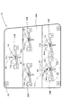
図10は、上記実施形態に係る車両用灯具10を右側灯具10Rとして備えた車両用灯具システム100を示すブロック図である。
FIG. 10 is a block diagram showing a
この車両用灯具システム100は、上記右側灯具10Rと、車体の前端左側部に設けられるヘッドランプとして構成された左側灯具10Lと、電流制御手段としてのコントロールユニット110とを備えてなっている。
The
左側灯具10Lは、右側灯具10Rを左右反転させた構造を有しているが、この左側灯具10Lにおいて、右側灯具10Rを構成する5つの灯具ユニット30A、30B、30C、30D、30Eに対応する5つの灯具ユニット30F、30G、30H、30I、30Jの各々の構成自体は、各灯具ユニット30A〜30Eを平行移動させた構成となっている。
The
左側灯具10Lにおいて、発光素子34、44の温度が最も高くなる灯具ユニット30I(または30J)の近傍には左側温度センサ60Lが設けられており、右側灯具10Rにおいて、発光素子34、44の温度が最も高くなる灯具ユニット30D(または30E)の近傍には右側温度センサ60Rが設けられている。そして、これら左側温度センサ60Lおよび右側温度センサ60Rの検出温度は、コントロールユニット110に入力されるようになっている。
In the
そして、コントロールユニット110は、各車両用灯具10L、10Rへの供給電流を、左側温度センサ60Lの検出温度と右側温度センサ60Rの検出温度とのうち高い方の値に応じた所定の電流値に設定するようになっている。
Then, the
このような構成を採用することにより、左側灯具10Lと右側灯具10Rとでその明るさを揃えることができるので、自車ドライバや対向車ドライバあるいは後続車ドライバ等に違和感を与えてしまうおそれをなくすことができる。
By adopting such a configuration, it is possible to make the brightness of the
図11は、上記車両用灯具システム100の変形例を示すブロック図である。
FIG. 11 is a block diagram showing a modified example of the
本変形例に係る車両用灯具システム200は、上記車両用灯具システム100と同様、左側灯具10Lと、右側灯具10Rと、コントロールユニット210とを備えた構成となっている。
Similar to the
本変形例においては、左側灯具10Lを構成する5つの灯具ユニット30F、30G、30H、30I、30Jと、右側灯具10Rを構成する5つの灯具ユニット30A、30B、30C、30D、30Eのうち、発光素子34、44の温度が最も高くなる右側灯具10Rの灯具ユニット30D(または30E)の近傍1箇所にのみ、温度センサ60が設けられている。
In this modification, light emission is performed among the five
なお、本変形例においては、予めエンジンルーム内の温度環境が把握されており、左側灯具10L周辺の雰囲気温度よりも右側灯具10R周辺の雰囲気温度の方が高いことが確認されていることを前提としている。
In this modification, it is assumed that the temperature environment in the engine room is grasped in advance, and it is confirmed that the ambient temperature around the
そして、この温度センサ60の検出温度は、コントロールユニット210に入力されるようになっており、コントロールユニット210は、各車両用灯具10L、10Rへの供給電流を、この温度センサ60の検出温度に応じた所定の電流値に設定するようになっている。
The temperature detected by the
このような構成を採用することにより、左側灯具10Lと右側灯具10Rとでその明るさを揃えることができるので、自車ドライバや対向車ドライバあるいは後続車ドライバ等に違和感を与えてしまうおそれをなくすことができる。
By adopting such a configuration, it is possible to make the brightness of the
しかも、このような構成を採用することによリ、温度センサ60の必要設置個数を最小限に抑えることができる。
In addition, by adopting such a configuration, the required number of
なお、右側灯具10R周辺の雰囲気温度よりも左側灯具10L周辺の雰囲気温度の方が高いことが確認されている場合には、左側灯具10Lの灯具ユニット30I(または30J)の近傍に温度センサ60を設けるようにすれば、本変形例と同様の作用効果を得ることができる。
If it is confirmed that the ambient temperature around the
10 車両用灯具
10L 左側灯具
10R 右側灯具
12 ランプボディ
14 透光カバー
16 インナパネル
16a 筒状開口部
18 エイミング機構
20 金属製支持部材
20A 鉛直パネル部
20B ユニット取付部
20C 放熱フィン
20a 凹溝部
30A、30B、30C、30D、30E、30F、30G、30H、30I、30J 灯具ユニット
32 投影レンズ
34、44 発光素子
34a、44a 発光チップ
36、46 リフレクタ
36a、46a 反射面
38 光制御部材
38a 上面
38a1 前端縁
40 支持プレート
42 弾性ブッシュ
50 エイミングスクリュウ
52 エイミングナット
60 温度センサ
60L 左側温度センサ
60R 右側温度センサ
60a 金属端子部
100、200 車両用灯具システム
110、210 コントロールユニット
Ax 光軸
CL1 水平カットオフライン
CL2 斜めカットオフライン
E エルボ点
F 後側焦点
HZ、HZ1、HZ2 ホットゾーン
PL ロービーム用配光パターン
PL1 拡散用配光パターン
PL2 集光用配光パターン
DESCRIPTION OF
Claims (4)
上記複数の灯具ユニットが、共通の金属製支持部材に支持されており、
上記複数の灯具ユニットとして、上記発光素子の発熱量が異なる第1および第2灯具ユニットを備えており、
上記第1および第2灯具ユニットが、上下方向に隣接して配置されており、
上記第1および第2灯具ユニットのうち、上記発熱量が相対的に大きい第1灯具ユニットが、上記発熱量が相対的に小さい第2灯具ユニットの下方側に配置されている、ことを特徴とする車両用灯具。 In a vehicular lamp comprising a plurality of lamp units each having a light emitting element as a light source,
The plurality of lamp units are supported by a common metal support member,
As the plurality of lamp units, the first and second lamp units having different heat generation amounts of the light emitting elements are provided,
The first and second lamp units are arranged adjacent to each other in the vertical direction,
Of the first and second lamp units, the first lamp unit having a relatively large calorific value is disposed below the second lamp unit having a relatively small calorific value. Vehicle lamp.
左側の車両用灯具を構成する複数の灯具ユニットのうち、上記発光素子の温度が最も高くなる灯具ユニットの近傍に設けられた左側温度センサと、
右側の車両用灯具を構成する複数の灯具ユニットのうち、上記発光素子の温度が最も高くなる灯具ユニットの近傍に設けられた右側温度センサと、
上記各車両用灯具への供給電流を、上記左側温度センサの検出温度と上記右側温度センサの検出温度とのうち高い方の値に応じた所定の電流値に設定する電流制御手段と、を備えてなることを特徴とする車両用灯具システム。 A vehicular lamp system according to claim 1, wherein the vehicular lamp is arranged on both left and right sides of the vehicle body,
Of the plurality of lamp units constituting the left vehicle lamp, the left temperature sensor provided in the vicinity of the lamp unit where the temperature of the light emitting element is highest,
Of the plurality of lamp units constituting the right vehicle lamp, the right temperature sensor provided in the vicinity of the lamp unit where the temperature of the light emitting element is highest,
Current control means for setting a supply current to each of the vehicle lamps to a predetermined current value corresponding to a higher value of the detected temperature of the left temperature sensor and the detected temperature of the right temperature sensor; A vehicular lamp system characterized by comprising:
左側の車両用灯具を構成する複数の灯具ユニットおよび右側の車両用灯具を構成する複数の灯具ユニットのうち、上記発光素子の温度が最も高くなる灯具ユニットの近傍に設けられた温度センサと、
上記各車両用灯具への供給電流を、上記温度センサの検出温度に応じた所定の電流値に設定する電流制御手段と、を備えてなることを特徴とする車両用灯具システム。 A vehicular lamp system according to claim 1, wherein the vehicular lamp is arranged on both left and right sides of the vehicle body,
Among the plurality of lamp units constituting the left vehicle lamp and the plurality of lamp units constituting the right vehicle lamp, a temperature sensor provided in the vicinity of the lamp unit having the highest temperature of the light emitting element;
A vehicle lamp system comprising: current control means for setting a current supplied to each of the vehicle lamps to a predetermined current value corresponding to a temperature detected by the temperature sensor.
Priority Applications (3)
| Application Number | Priority Date | Filing Date | Title |
|---|---|---|---|
| JP2005165937A JP4397856B2 (en) | 2005-06-06 | 2005-06-06 | Vehicle lamp and vehicle lamp system |
| US11/442,862 US7686488B2 (en) | 2005-06-06 | 2006-05-30 | Vehicle lamp and vehicle lamp system |
| DE102006025997A DE102006025997B4 (en) | 2005-06-06 | 2006-06-02 | Vehicle light and vehicle light system |
Applications Claiming Priority (1)
| Application Number | Priority Date | Filing Date | Title |
|---|---|---|---|
| JP2005165937A JP4397856B2 (en) | 2005-06-06 | 2005-06-06 | Vehicle lamp and vehicle lamp system |
Publications (2)
| Publication Number | Publication Date |
|---|---|
| JP2006335328A JP2006335328A (en) | 2006-12-14 |
| JP4397856B2 true JP4397856B2 (en) | 2010-01-13 |
Family
ID=37440194
Family Applications (1)
| Application Number | Title | Priority Date | Filing Date |
|---|---|---|---|
| JP2005165937A Expired - Fee Related JP4397856B2 (en) | 2005-06-06 | 2005-06-06 | Vehicle lamp and vehicle lamp system |
Country Status (3)
| Country | Link |
|---|---|
| US (1) | US7686488B2 (en) |
| JP (1) | JP4397856B2 (en) |
| DE (1) | DE102006025997B4 (en) |
Families Citing this family (23)
| Publication number | Priority date | Publication date | Assignee | Title |
|---|---|---|---|---|
| EP1898144A3 (en) * | 2006-09-08 | 2010-08-25 | Robert Bosch Gmbh | Lighting device with several LED components and method for its manufacture |
| DE102006059592A1 (en) | 2006-12-16 | 2008-06-19 | Bayerische Motoren Werke Ag | Automobile headlights |
| JP2008166412A (en) * | 2006-12-27 | 2008-07-17 | Koito Mfg Co Ltd | Light-emitting element driving circuit, and lighting equipment for vehicle |
| JP2008243434A (en) | 2007-03-26 | 2008-10-09 | Koito Mfg Co Ltd | Lamp tool unit of vehicle headlight |
| JP5145190B2 (en) * | 2008-03-13 | 2013-02-13 | 株式会社小糸製作所 | Vehicle headlamp |
| JP5062429B2 (en) * | 2008-03-31 | 2012-10-31 | スタンレー電気株式会社 | Lighting device |
| JP5405043B2 (en) * | 2008-04-22 | 2014-02-05 | 株式会社小糸製作所 | Vehicle lighting |
| DE102008036194B4 (en) * | 2008-08-02 | 2016-10-20 | Automotive Lighting Reutlingen Gmbh | Light module for a lighting device for a motor vehicle |
| JP5352263B2 (en) | 2009-02-06 | 2013-11-27 | 株式会社小糸製作所 | Vehicle lighting |
| US20100213868A1 (en) * | 2009-02-20 | 2010-08-26 | Yung-Fa Lin | Vehicle multifunctional lamp |
| TWI378051B (en) * | 2010-02-26 | 2012-12-01 | Univ Nat Taipei Technology | Road-adapting headlight for motorcycles |
| JP5646264B2 (en) * | 2010-09-28 | 2014-12-24 | 株式会社小糸製作所 | Vehicle lighting |
| JP5675272B2 (en) * | 2010-10-28 | 2015-02-25 | 株式会社小糸製作所 | Vehicle lamp |
| US8931938B2 (en) | 2011-08-29 | 2015-01-13 | J.W. Speaker, Corporation | Locomotive LED/optics headlight assembly |
| DE102012219707B4 (en) * | 2012-07-12 | 2024-12-05 | Automotive Lighting Reutlingen Gmbh | Method for controlling the light module of a motor vehicle headlight, control unit and headlight |
| JP2014127238A (en) * | 2012-12-25 | 2014-07-07 | Koito Mfg Co Ltd | Headlight for vehicle |
| US8845153B2 (en) * | 2013-02-06 | 2014-09-30 | Wen-Sung Lee | High beam and low beam combination lamp for a bicycle |
| AT514022B1 (en) * | 2013-03-07 | 2015-11-15 | Zizala Lichtsysteme Gmbh | Lighting device for a vehicle headlight and vehicle headlights |
| WO2015016068A1 (en) * | 2013-08-02 | 2015-02-05 | 株式会社小糸製作所 | Vehicle lamp |
| DE102017217897A1 (en) * | 2017-10-09 | 2019-04-11 | Osram Gmbh | Lamp with yellow and with white and / or blue light source group |
| DE102019205641B4 (en) * | 2019-04-17 | 2022-09-29 | Audi Ag | Lighting device for a motor vehicle for generating a light animation |
| CN114341545B (en) * | 2019-07-08 | 2024-12-24 | 亮锐控股有限公司 | Supports for light emitting elements and lighting equipment |
| KR102704123B1 (en) * | 2019-11-01 | 2024-09-06 | 에스엘 주식회사 | Lamp for vehicle |
Family Cites Families (8)
| Publication number | Priority date | Publication date | Assignee | Title |
|---|---|---|---|---|
| JPH0782761B2 (en) * | 1990-09-26 | 1995-09-06 | 株式会社小糸製作所 | Headlamps for automobiles with integrated clearance lamps |
| US6152590A (en) * | 1998-02-13 | 2000-11-28 | Donnelly Hohe Gmbh & Co. Kg | Lighting device for motor vehicles |
| JP2002189220A (en) * | 2000-12-21 | 2002-07-05 | Nippon Seiki Co Ltd | Light emitting device and liquid crystal display device having the same |
| DE10214447A1 (en) | 2002-03-30 | 2003-10-16 | Hella Kg Hueck & Co | Control device for controlling electrical lamps and headlights with such a control device |
| JP4102240B2 (en) | 2003-04-08 | 2008-06-18 | 株式会社小糸製作所 | Vehicle headlamp |
| JP4251941B2 (en) * | 2003-08-08 | 2009-04-08 | 三菱電機株式会社 | head lamp |
| EP1515368B1 (en) * | 2003-09-05 | 2019-12-25 | Nichia Corporation | Light equipment |
| JP4115921B2 (en) * | 2003-11-04 | 2008-07-09 | 株式会社小糸製作所 | Vehicle headlamp |
-
2005
- 2005-06-06 JP JP2005165937A patent/JP4397856B2/en not_active Expired - Fee Related
-
2006
- 2006-05-30 US US11/442,862 patent/US7686488B2/en not_active Expired - Fee Related
- 2006-06-02 DE DE102006025997A patent/DE102006025997B4/en not_active Expired - Fee Related
Also Published As
| Publication number | Publication date |
|---|---|
| JP2006335328A (en) | 2006-12-14 |
| US20060274544A1 (en) | 2006-12-07 |
| DE102006025997A1 (en) | 2006-12-14 |
| US7686488B2 (en) | 2010-03-30 |
| DE102006025997B4 (en) | 2009-06-10 |
Similar Documents
| Publication | Publication Date | Title |
|---|---|---|
| JP4397856B2 (en) | Vehicle lamp and vehicle lamp system | |
| JP4053489B2 (en) | Vehicle headlamp | |
| JP4527024B2 (en) | Vehicle lighting | |
| JP4102240B2 (en) | Vehicle headlamp | |
| JP4515391B2 (en) | Vehicle headlamp | |
| JP4264335B2 (en) | Vehicle headlamp | |
| JP4360191B2 (en) | Vehicle headlamp | |
| JP4707189B2 (en) | Vehicle lamp | |
| JP4781951B2 (en) | Vehicle lamp unit and vehicle lamp | |
| JP4413762B2 (en) | Lighting fixtures for vehicles | |
| JP5133861B2 (en) | Lighting fixtures for vehicles | |
| JP2005166590A (en) | Vehicle headlamp | |
| JP2005141919A (en) | Vehicular headlight | |
| JP6211349B2 (en) | Vehicle lighting | |
| JP2014007049A (en) | Optical system unit and vehicular lighting device | |
| JP2014007106A (en) | Lamp for vehicle | |
| JP5839677B2 (en) | Lighting fixtures for vehicles | |
| JP2007234562A (en) | Lamp unit for vehicular headlamp | |
| JP2006179246A (en) | Vehicular headlamp unit | |
| WO2019124188A1 (en) | Vehicle headlight | |
| JP4527165B2 (en) | Vehicle headlamp | |
| JP2011103214A (en) | Optical unit | |
| JP2005166588A (en) | Vehicular headlamp | |
| JP7285362B2 (en) | vehicle headlight | |
| JP6143310B2 (en) | Vehicle lighting |
Legal Events
| Date | Code | Title | Description |
|---|---|---|---|
| A621 | Written request for application examination |
Free format text: JAPANESE INTERMEDIATE CODE: A621 Effective date: 20080324 |
|
| A977 | Report on retrieval |
Free format text: JAPANESE INTERMEDIATE CODE: A971007 Effective date: 20091007 |
|
| TRDD | Decision of grant or rejection written | ||
| A01 | Written decision to grant a patent or to grant a registration (utility model) |
Free format text: JAPANESE INTERMEDIATE CODE: A01 Effective date: 20091020 |
|
| A01 | Written decision to grant a patent or to grant a registration (utility model) |
Free format text: JAPANESE INTERMEDIATE CODE: A01 |
|
| A61 | First payment of annual fees (during grant procedure) |
Free format text: JAPANESE INTERMEDIATE CODE: A61 Effective date: 20091021 |
|
| FPAY | Renewal fee payment (event date is renewal date of database) |
Free format text: PAYMENT UNTIL: 20121030 Year of fee payment: 3 |
|
| R150 | Certificate of patent or registration of utility model |
Free format text: JAPANESE INTERMEDIATE CODE: R150 |
|
| FPAY | Renewal fee payment (event date is renewal date of database) |
Free format text: PAYMENT UNTIL: 20121030 Year of fee payment: 3 |
|
| FPAY | Renewal fee payment (event date is renewal date of database) |
Free format text: PAYMENT UNTIL: 20131030 Year of fee payment: 4 |
|
| LAPS | Cancellation because of no payment of annual fees |