JP4391564B2 - Bi-directional optical transceiver module using single-core optical fiber cable - Google Patents
Bi-directional optical transceiver module using single-core optical fiber cable Download PDFInfo
- Publication number
- JP4391564B2 JP4391564B2 JP2007516378A JP2007516378A JP4391564B2 JP 4391564 B2 JP4391564 B2 JP 4391564B2 JP 2007516378 A JP2007516378 A JP 2007516378A JP 2007516378 A JP2007516378 A JP 2007516378A JP 4391564 B2 JP4391564 B2 JP 4391564B2
- Authority
- JP
- Japan
- Prior art keywords
- module
- lens
- light
- optical
- optical fiber
- Prior art date
- Legal status (The legal status is an assumption and is not a legal conclusion. Google has not performed a legal analysis and makes no representation as to the accuracy of the status listed.)
- Expired - Fee Related
Links
Images


Classifications
-
- G—PHYSICS
- G02—OPTICS
- G02B—OPTICAL ELEMENTS, SYSTEMS OR APPARATUS
- G02B6/00—Light guides; Structural details of arrangements comprising light guides and other optical elements, e.g. couplings
- G02B6/24—Coupling light guides
- G02B6/42—Coupling light guides with opto-electronic elements
-
- G—PHYSICS
- G02—OPTICS
- G02B—OPTICAL ELEMENTS, SYSTEMS OR APPARATUS
- G02B6/00—Light guides; Structural details of arrangements comprising light guides and other optical elements, e.g. couplings
- G02B6/24—Coupling light guides
- G02B6/42—Coupling light guides with opto-electronic elements
- G02B6/4201—Packages, e.g. shape, construction, internal or external details
- G02B6/4255—Moulded or casted packages
-
- G—PHYSICS
- G02—OPTICS
- G02B—OPTICAL ELEMENTS, SYSTEMS OR APPARATUS
- G02B6/00—Light guides; Structural details of arrangements comprising light guides and other optical elements, e.g. couplings
- G02B6/24—Coupling light guides
- G02B6/42—Coupling light guides with opto-electronic elements
- G02B6/4201—Packages, e.g. shape, construction, internal or external details
- G02B6/4274—Electrical aspects
- G02B6/4277—Protection against electromagnetic interference [EMI], e.g. shielding means
-
- G—PHYSICS
- G02—OPTICS
- G02B—OPTICAL ELEMENTS, SYSTEMS OR APPARATUS
- G02B6/00—Light guides; Structural details of arrangements comprising light guides and other optical elements, e.g. couplings
- G02B6/24—Coupling light guides
- G02B6/42—Coupling light guides with opto-electronic elements
- G02B6/4201—Packages, e.g. shape, construction, internal or external details
- G02B6/4204—Packages, e.g. shape, construction, internal or external details the coupling comprising intermediate optical elements, e.g. lenses, holograms
- G02B6/4206—Optical features
-
- G—PHYSICS
- G02—OPTICS
- G02B—OPTICAL ELEMENTS, SYSTEMS OR APPARATUS
- G02B6/00—Light guides; Structural details of arrangements comprising light guides and other optical elements, e.g. couplings
- G02B6/24—Coupling light guides
- G02B6/42—Coupling light guides with opto-electronic elements
- G02B6/4201—Packages, e.g. shape, construction, internal or external details
- G02B6/4204—Packages, e.g. shape, construction, internal or external details the coupling comprising intermediate optical elements, e.g. lenses, holograms
- G02B6/4214—Packages, e.g. shape, construction, internal or external details the coupling comprising intermediate optical elements, e.g. lenses, holograms the intermediate optical element having redirecting reflective means, e.g. mirrors, prisms for deflecting the radiation from horizontal to down- or upward direction toward a device
-
- G—PHYSICS
- G02—OPTICS
- G02B—OPTICAL ELEMENTS, SYSTEMS OR APPARATUS
- G02B6/00—Light guides; Structural details of arrangements comprising light guides and other optical elements, e.g. couplings
- G02B6/24—Coupling light guides
- G02B6/42—Coupling light guides with opto-electronic elements
- G02B6/4201—Packages, e.g. shape, construction, internal or external details
- G02B6/4246—Bidirectionally operating package structures
-
- H—ELECTRICITY
- H01—ELECTRIC ELEMENTS
- H01L—SEMICONDUCTOR DEVICES NOT COVERED BY CLASS H10
- H01L2224/00—Indexing scheme for arrangements for connecting or disconnecting semiconductor or solid-state bodies and methods related thereto as covered by H01L24/00
- H01L2224/01—Means for bonding being attached to, or being formed on, the surface to be connected, e.g. chip-to-package, die-attach, "first-level" interconnects; Manufacturing methods related thereto
- H01L2224/42—Wire connectors; Manufacturing methods related thereto
- H01L2224/47—Structure, shape, material or disposition of the wire connectors after the connecting process
- H01L2224/48—Structure, shape, material or disposition of the wire connectors after the connecting process of an individual wire connector
- H01L2224/4805—Shape
- H01L2224/4809—Loop shape
- H01L2224/48091—Arched
-
- H—ELECTRICITY
- H01—ELECTRIC ELEMENTS
- H01L—SEMICONDUCTOR DEVICES NOT COVERED BY CLASS H10
- H01L2224/00—Indexing scheme for arrangements for connecting or disconnecting semiconductor or solid-state bodies and methods related thereto as covered by H01L24/00
- H01L2224/01—Means for bonding being attached to, or being formed on, the surface to be connected, e.g. chip-to-package, die-attach, "first-level" interconnects; Manufacturing methods related thereto
- H01L2224/42—Wire connectors; Manufacturing methods related thereto
- H01L2224/47—Structure, shape, material or disposition of the wire connectors after the connecting process
- H01L2224/48—Structure, shape, material or disposition of the wire connectors after the connecting process of an individual wire connector
- H01L2224/481—Disposition
- H01L2224/48151—Connecting between a semiconductor or solid-state body and an item not being a semiconductor or solid-state body, e.g. chip-to-substrate, chip-to-passive
- H01L2224/48221—Connecting between a semiconductor or solid-state body and an item not being a semiconductor or solid-state body, e.g. chip-to-substrate, chip-to-passive the body and the item being stacked
- H01L2224/48245—Connecting between a semiconductor or solid-state body and an item not being a semiconductor or solid-state body, e.g. chip-to-substrate, chip-to-passive the body and the item being stacked the item being metallic
- H01L2224/48247—Connecting between a semiconductor or solid-state body and an item not being a semiconductor or solid-state body, e.g. chip-to-substrate, chip-to-passive the body and the item being stacked the item being metallic connecting the wire to a bond pad of the item
Landscapes
- Physics & Mathematics (AREA)
- General Physics & Mathematics (AREA)
- Optics & Photonics (AREA)
- Electromagnetism (AREA)
- Optical Couplings Of Light Guides (AREA)
- Semiconductor Lasers (AREA)
- Optical Communication System (AREA)
Description
本発明は光ファイバーケーブルを使用した光トランシーバーモジュール、つまり単芯の波長の異なる2波長の光源を使って、双方向送信が可能な光トランシーバーモジュールに関するものである。 The present invention relates to an optical transceiver module using an optical fiber cable, that is, an optical transceiver module capable of bidirectional transmission using two-wavelength light sources having different single-core wavelengths.
光通信での電気から光への変換とは、デジタル電気信号入力からの電気信号を発光デバイスのオンかオフで、光信号へ変換することを意味し、また、光から電気への変換は、光ケーブルを通って伝えられた光信号を受信する受光デバイスによって光信号から電気信号へ変換することを意味する。大容量のデータは光通信によって長距離を送信することができる。 The conversion from electricity to light in optical communication means that an electric signal from a digital electric signal input is converted into an optical signal when the light emitting device is turned on or off, and the conversion from light to electricity is It means that an optical signal is converted from an optical signal to an electrical signal by a light receiving device that receives the optical signal transmitted through the optical cable. Large volumes of data can be transmitted over long distances by optical communication.
データの送信と受信のための光ケーブルが、2つの異なる場所から同時にデータを送信、受信するのに必要である。光ケーブル自体には指向性がないため、光はケーブルのAからBまで送信され、反対に光はBからAまで送信されることが可能である。それは光データが単芯の光ケーブルを使って、双方向に送信できることを意味している。しかし発光デバイスからの光信号と受光デバイスへの光信号は分かれているべきで、モジュールは光信号の送信と受信を図1に示したように分けることが必要であった。 Optical cables for data transmission and reception are necessary to transmit and receive data simultaneously from two different locations. Since the optical cable itself is not directional, light can be transmitted from A to B of the cable, and conversely, light can be transmitted from B to A. That means that optical data can be transmitted bi-directionally using a single-core optical cable. However, the optical signal from the light emitting device should be separated from the optical signal to the light receiving device, and the module was required to separate the transmission and reception of the optical signal as shown in FIG.
図1はこれまでの双方向の光トランシーバーモジュールの配線図である。効果的に送受信信号を分けるために、2つの異なる波長11、12の光が、各点で使われる。例えばもし、波長11の発光デバイス104がA地点で使われていれば、波長12の発光デバイス104bがB地点で使われる。一般に、発光ダイオードLEDあるいはレーザーダイオードLDが発光デバイス104、104bとして使われ、フォトダイオードPDは受光デバイス105、105bとして使われる。図1に示されるように、A地点の発光デバイス104から発せられた波長11の光が光フィルター101を通じ受光デバイス105に向かった場合、光フィルター102が反射し、そしてそのため、波長11の光は光ケーブル107に入り、A地点の受光デバイス105に行くことができない。 同じ原理はB点に適用し、これは1つの光ケーブル107での双方向光通信を可能にする。
FIG. 1 is a wiring diagram of a conventional bidirectional optical transceiver module. In order to effectively separate transmitted and received signals, light of two
上記のような従来の双方向光トランシーバーモジュールには高価な金属のTO缶パッケージを使わなければならないことと、レンズ、光学フィルター101、102、光ケーブル107のアセンブリのために、精密なレンズの光学的位置合せが要求されるという問題がある。光学的位置合せを行うために、TO缶パッケージ104の中の発光デバイスは発光していることが必要である。光トランシーバーモジュールの中のデバイスと光コンポーネントは、反対側の光トランシーバーモジュールの中の受光デバイス105に光を送るため、精密な光学的位置合せのプロセスを必要とする。光学的位置合せが完了した後、発光デバイス104と受光デバイス105は金属のボディー103と溶接される。上記のような光学的位置合せプロセスがアクティブアラインメントと呼ばれる。アクティブアラインメントはアセンブリのために相当な時間を必要とし、位置合せの機能を持ったレーザー溶接マシンのような非常に高価な機器を必要とする。上記の問題を克服するために、アクティブプロセスのないパッシブアラインメントプロセスが考案された。 パッシブアラインメントのプロセスは光デバイスの位置を合せるのに、光学的位置合せプロセスの代わりに、既に位置合せされた構造を使用する。通常、光デバイスのような光導波管や、半導体プロセスに基づくシリコンオプティカルベンチが使用されている。又は、光導波管とシリコンオプティカルベンチの組み合わせが可能である。
The conventional bi-directional optical transceiver module as described above requires the use of an expensive metal TO can package and the assembly of the lens,
特に、光導波管は同じような動作原理を使用し、光を限定された空間構造に伝播させるデバイスである。光は、より低い屈折率材料で囲まれた中心を通って伝わる。半導体製造工程を使うので光導波管は1mmの精度の範囲内で製造することができる。一度光が光導波路に入射すると、光は限定され、主に内部中心に導かれるので、光は位置合せなしで特定のポジションに伝えられることができる。光学的位置合せは光ファイバー、光学フィルター、受光デバイス、発光デバイスをアレンジすることで得られる。光導波管自体は正確に製造されることができるが、しかし、予め位置合わせされた構造が、光導波路、受光デバイス、発光デバイスを特定の位置に配置するのに必要である。正確に予め位置合わせされた構造はシリコンオプティカルベンチを使用して実装される。シリコンオプティカルベンチへの組み立て工程は以下に説明されている。 In particular, an optical waveguide is a device that uses similar operating principles to propagate light to a limited spatial structure. Light travels through a center surrounded by a lower refractive index material. Since the semiconductor manufacturing process is used, the optical waveguide can be manufactured within an accuracy range of 1 mm. Once the light is incident on the optical waveguide, the light is limited and mainly guided to the inner center, so that the light can be transmitted to a specific position without alignment. Optical alignment is obtained by arranging optical fibers, optical filters, light receiving devices, and light emitting devices. The optical waveguide itself can be accurately manufactured, but a pre-aligned structure is required to place the optical waveguide, light receiving device, and light emitting device at specific locations. A precisely pre-aligned structure is implemented using a silicon optical bench. The assembly process to the silicon optical bench is described below.
特定のパターンの形成された薄いフィルムがフォトリソグラフィー工程を使用しシリコン基板の上に実装される。 特定のパターンの形成された溝はエッチング溶液にシリコン基板を浸すことと、選択的に、パターンされた薄いフィルムでエッチング溶液を遮断することで形成される。組み立てられた構造はシリコンオプティカルベンチと呼ばれ、光導波管を挿入することと、受光デバイス、発光デバイスをシリコンオプティカルベンチの組み立てられた溝の上に差し込むことで良好なアライメントを得ることができる。示されているような、半導体工程を使用した光学的位置合わせの成されたコンポーネントはとても高い精密さがあるが、組み立て工程は簡単ではなく、低価格大量生産には適さない。 それらの精密な部品はアセンブルされる他の部品を必要とし、そのためすべての部品が半導体工程で製造されない限り、必要とされている確度は維持されない。 しかし半導体工程を使用して全ての装置の製造が実際には可能なわけではなくて、この問題のための解決が必要とされる。 A thin film with a specific pattern is mounted on a silicon substrate using a photolithography process. The groove with a specific pattern is formed by immersing the silicon substrate in an etching solution and optionally blocking the etching solution with a patterned thin film. The assembled structure is called a silicon optical bench, and good alignment can be obtained by inserting an optical waveguide and inserting the light receiving device and the light emitting device into the assembled groove of the silicon optical bench. As shown, optically aligned components using semiconductor processes are very precise, but the assembly process is not simple and is not suitable for low cost mass production. Those precision parts require other parts to be assembled, so the required accuracy is not maintained unless all parts are manufactured in a semiconductor process. However, not all devices can be manufactured in practice using semiconductor processes, and a solution to this problem is needed.
本発明の目的は、モジュール化された発光デバイス、受光デバイス、フィルター及びレンズで形成された、単芯光ファイバーケーブルを用いる双方向光トランシーバーモジュールを提供することであり、そしてそれらの光学的位置合わせはそれらを個別に接続することで完成され、本発明によって低価格大量生産が可能となる。本発明のもう1つの目的は、低価格大量生産を可能にするプラスチック射出成型を使って、単芯光ファイバーケーブルを使用した双方向光トランシーバーモジュールを提供することである。本発明のもう1つの目的は、静電遮蔽を可能とする送信モジュール及び受信モジュールを提供することである。 An object of the present invention is to provide a bi-directional optical transceiver module using a single-core optical fiber cable formed of modularized light emitting devices, light receiving devices, filters and lenses, and their optical alignment is They are completed by connecting them individually, and the present invention enables mass production at a low price. Another object of the present invention is to provide a bi-directional optical transceiver module using single-core optical fiber cable using plastic injection molding that allows low cost mass production. Another object of the present invention is to provide a transmission module and a reception module that enable electrostatic shielding.
本発明の目的を達成するために、本発明は、発光デバイスを含む送信モジュール;受光デバイスを含む受信モジュール;送受信の光を分けているフィルターモジュール;そして送信モジュール、受信モジュール、フィルターモジュール、及び光ファイバーケーブルに接続したレンズモジュール、を含んで構成され、そしてそれらをそれぞれ接続することによって、光学的位置合わせを完成する。 To achieve the object of the present invention, the present invention provides a transmission module including a light emitting device; a reception module including a light receiving device; a filter module separating transmission and reception light; and a transmission module, a reception module, a filter module, and an optical fiber. A lens module connected to the cable, and connecting each of them completes the optical alignment.
最も望ましい、送信モジュール、受信モジュール、レンズモジュール及びフィルターモジュールを組み立てる方法は、それぞれをプラスチック射出成型で形成することである。レンズモジュールは、光ファイバーケーブルを接続している容器を含んでおり;特定の位置で、レンズモジュールと送信モジュールを接続している第1接続部を含み;特定の位置で、レンズモジュールと受信モジュールを接続している第2接続部を含み; そして特定の位置でレンズモジュールとフィルターモジュールを接続している第3接続部、を含んでいる。 The most desirable method for assembling the transmission module, the reception module, the lens module, and the filter module is to form each by plastic injection molding. The lens module includes a container that connects the optical fiber cable; includes a first connection portion that connects the lens module and the transmission module at a specific position; and the lens module and the reception module at the specific position. A second connecting portion connected; and a third connecting portion connecting the lens module and the filter module at a specific position.
本発明によると、 発光デバイスが実装された送信モジュールと受光デバイスが実装された受信モジュールはガイド溝によってレンズモジュールと接続されている。そして正確に機械でモールドされたガイドピンと発光デバイス、受光デバイスと光ファイバーケーブルは単にそれぞれのモジュールを接続することにより正確にアラインされる。そしてレンズモジュールの中に形成されたレンズが効果的に光ファイバーケーブルに集光することを可能にする。更にレンズモジュールを含むすべての部品がプラスチック射出成型プロセスで製造され、これが低価格大量生産を可能とする。 According to the present invention, the transmission module on which the light emitting device is mounted and the reception module on which the light receiving device is mounted are connected to the lens module by the guide groove. And precisely machined guide pins and light emitting devices, light receiving devices and fiber optic cables are accurately aligned by simply connecting the respective modules. Then, the lens formed in the lens module can be effectively focused on the optical fiber cable. In addition, all parts including the lens module are manufactured by a plastic injection molding process, which enables low-cost mass production.
しかし、この発明は添付の図を参考とした例として充分に述べられてきたが、この技術に精通した人にとっては、多くの変更と改良が行われることが明らかであることにも注意しておくべきである。従ってそのような変更と改良が本発明の範囲から外れない限り、それらはそこに含まれていることとして解釈されるべきである。 However, although the present invention has been fully described by way of example with reference to the accompanying drawings, it should also be noted that many variations and modifications will be apparent to those skilled in the art. Should be kept. Therefore, unless such changes and modifications fall within the scope of the invention, they should be construed as being included therein.
光トランシーバーモジュールはデジタル信号を入力として受け取り、発光デバイスを使って、それを光学的な信号に変え、反対側のトランシーバーモジュールに送信し、逆に反対側で光トランシーバーモジュールからの光信号を受け取り、光信号に変換する。光信号の送信と受信は単芯の光ファイバーケーブルを使うので、送信と受信の各々の光学的な波長が異なるものとする。 The optical transceiver module receives a digital signal as input, uses a light emitting device to turn it into an optical signal, sends it to the opposite transceiver module, and conversely receives the optical signal from the optical transceiver module on the opposite side, Convert to optical signal. Since transmission and reception of optical signals use single-core optical fiber cables, it is assumed that the optical wavelengths of transmission and reception are different.
本発明は、光発光デバイス204と受光デバイス205を含む送信モジュール223と受信モジュール224それぞれをプラスチック射出成型モールディングで組み立てられたレンズモジュール221に接続することによって光アライメントを完成する。
The present invention completes optical alignment by connecting each of the
送信モジュール223は発光デバイス204を含み、発光ダイオード(LED)あるいは面発光レーザー(VCSEL)が一般に発光デバイスとして使われる。送信モジュール223はデジタル電気信号を入力として受け取り、発光デバイスを使って光シグナルに変換し、反対側の光トランシーバーモジュールに送信する。
The
受信モジュール224は受光デバイス205を含んでいて、光を電気信号に変換し、一般にフォトダイオードが受光デバイスとして使われる。受信モジュール224は、受光デバイスを使用し、反対側の光トランシーバーモジュールから送信された光シグナルを受信し、電気信号に変換する。
The
レンズモジュール221とフィルターモジュール222は、送受信された光シグナルを分離する。そのため、双方向の光通信が単芯の光ファイバーケーブルで可能である。送信レンズ211を含むレンズモジュール221が送信モジュール223からの光を平行にしている。受信レンズ212は受信モジュール224の内部に有る受光デバイス205に光を収束している。そしで、レセプタクルレンズ213が、光を、光ファイバーケーブルに収束し、同時に、光ファイバーケーブルからの光を、平行にする。送受信された光シグナルを効果的に分離するため、送信と受信の波長は異なるべきで、フィルターモジュール222内の光フィルター201が使用される。フィルターモジュール222は送信と受信の間の光シグナルを分離する。光フィルター202は受信モジュール224の前にあって送信モジュール223からの光を遮る。
The
2つの光シグナルの分離は、2つの光フィルター201、202を使用することによって実行される。1つの光フィルター202は長波光を反射して、短波の光を送信する。もう1つは逆に光フィルター201が長波光を伝えて、短波の光を反射する。A地点での1つの送信モジュール223は発光デバイス204を使用し長波光を発光し、B地点でのもう1つの送信デバイスは発光デバイス204bを使用し短波の光を発光する。長波長と短波長はそれぞれ相対的な値を意味し、絶対的な値を意味する訳ではない。長波長と短波長との違いはある範囲の中で変化に富み、どの違いも、光フィルターで分けられる。例えば、850nmVCSELと780nmVCSELはそれぞれ光発光デバイスとして使用される。光フィルターは45度の角度で、光ファイバーケーブル207と送信モジュールの間に挿入される。
Separation of the two optical signals is performed by using two
図4は図2のフィルターモジュールのレンズモジュールを示す。ガイドピン433、434は、部品を挿入し、送信モジュール223と受信モジュール224を正確にアラインするためモジュールに形成されたものである。レンズモジュール221はプラスチックの射出成型によって製造されたものである。前述のレンズ211、212、213、挿入部分422、423、424及びガイドピン433、434は射出成形で完全に統合された部品に形成される。光がレンズモジュールを通して伝わるので、レンズモジュール221の素材は透明であるものとする。透明のポリメチル・メタクリレート(PMMA)やポリカーボネイト(PC)が素材として使用可能である。
FIG. 4 shows a lens module of the filter module of FIG. The guide pins 433 and 434 are formed in the module in order to insert components and align the
図5は図4のフィルターモジュールを拡大図である。 フィルターモジュール222はレンズモジュール221に光フィルター201を簡単に挿入するために、分離した部品として製造されたものである。光フィルターの外形寸法は1mm×1mmで、厚さが0.1〜0.2mmである。光フィルター201の取扱いと挿入は、単体では小さく薄いサイズのためにとても難しい。正確に光フィルターを挿入しアラインするために、挿入された光フィルター201を含むフィルターモジュール222は使用される。 フィルターモジュール222には光フィルター201を挿入するためのベース501がある。 ベースには光を伝えるためのスルーホールがある。フィルターモジュールは扱いやすく、光フィルターより大きいサイズなのでレンズモジュールに挿入するのが簡単である。フィルターモジュールのトップの部分は、ほこりのような異物からレンズモジュールの内部を保護するためにカバーとして使うことが可能である。フィルターモジュールは従来のプラスチック射出成型で製造される。
FIG. 5 is an enlarged view of the filter module of FIG. The
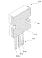
図6は発光デバイスから光ファイバーケーブルまでのビーム光軌道を示している。図7は光ファイバーケーブルから受光デバイスまでのビーム光軌道を示している。図8は図2の送信モジュールの構造を示している。 FIG. 6 shows the light beam trajectory from the light emitting device to the optical fiber cable. FIG. 7 shows the beam light trajectory from the optical fiber cable to the light receiving device. FIG. 8 shows the structure of the transmission module of FIG.
送信モジュール223は光発光デバイスに電気信号を伝達するメタルリードフレーム804a、804bを含み、発光デバイスをリードフレームの特定の位置に挿入するため四角い穴が形成される。そして、発光デバイスが、四角い穴に挿入される。ガイド溝801はレンズモジュール221のガイドピン(図4の433)に接続するために、送信モジュール223の両サイドに形成されたものである。レンズモジュールのガイドピンが送信モジュールのガイド溝に接続するとき、送信側のレンズモジュールの中心と発光デバイスの発光ポイントの中心が適合する。送信モジュールはプラスチック射出成型で形作られる。
The
メタルリードフレーム804bは送信モジュールの発光デバイス204を挿入された四角い穴の下側で露出されている。そして発光デバイスは少量の電気的に導電な接着剤を四角い穴の中のメタルリードフレームの露出した表面に施した後、表面に実装され、そして、リードフレーム804bと発光デバイスの下側が電気的に接続される。発光デバイスの上部のメタルパッドともうひとつのリードフレーム804aは細い金属のワイヤー802を使用することによって接続される。そうすることにより、電流シグナルはリードフレーム804a、804bを通して転送される。
The
図9は図2の受信モジュールの構造を示す。受信モジュール224はメタルリードフレーム904a、904b、904cを含み、受光デバイス205から作られた電気信号を転送する。そして四角い穴がリードフレームの特定のポジションに受光デバイスを挿入するために形成される。受信モジュール224がレンズモジュール221に接続する時、その溝は受光口径の中心とレンズの中心が適合するようにプレアラインされる。受光デバイス205に加えて、受光デバイス205から作られた電気信号を増幅するためのプリアンプIC905と他の部品として、コンデンサー906がプリアンプを駆動するために挿入されている。ガイド溝901はレンズモジュール221のガイドピン434に接続するために受信モジュール224の両サイドに形成されている。受信モジュールは射出成型で形成されている。メタルリードフレーム904cは受信モジュール224の受光デバイス205を挿入した四角い穴の下側に露出している。そして、受光デバイスは少量の電気的に導電な接着剤を四角い穴の内部のメタルリードフレームの露出した表面に施した後、表面に実装される。その後、リードフレーム904cと下部の受光デバイスは電気的に接続される。受光デバイスの下部はリードフレーム904cを通して接続され、リードフレームは細いメタルワイヤー902を通して、プリアンプ905に接続されている。受光デバイス205の上部メタルパッドはプリアンプ905に細いメタルワイヤー902を使って直接接続されている。プリアンプは、他のリードフレームの表面に電気的に導電な接着剤を施すことによって、実装される。延長したメタルリードフレーム911はプレアンプの下部表面に接続されており、電気遮蔽をするための金属カバーを意味し、903はプラスチック射出成型で形成された受信モジュールの本体を意味する。光フィルター202は受光デバイス205の上に実装され、エポキシボンドのような接着剤で固定される。光フィルター202は送信モジュールから来る光信号以外の迷光を遮断する。
FIG. 9 shows the structure of the receiving module of FIG. The
図10は図9で遮られた受信モジュールの構造を示す。レシーバーモジュールは延長されたメタルリードフレームで覆れており、図10で示されるように、延長されたメタルリードフレームを折りたたむことによってアースされている。これにより受信モジュールの内部が電気的に遮蔽される。1001は受光デバイスに光を送るスルーホールを意味する。上に示された電気の遮蔽は、プリアンプから放たれた高周波シグナルによる電磁波が外部に放射されるのを防ぎ、そしてフォトダイオードの出力信号を外部から結合された電磁波から守る。加えて、外部からの迷光を遮断することにより光シグナルの検出感度を増すことができる。
FIG. 10 shows the structure of the receiving module blocked in FIG. The receiver module is covered with an extended metal lead frame and is grounded by folding the extended metal lead frame as shown in FIG. As a result, the interior of the receiving module is electrically shielded.
本発明はデータ通信網のように高速デジタルデータ伝達のために広く使われるものとする。例えばデータコムネットワーク、アクセスネットワーク、宅内ネットワーク、ストレージエリアネットワーク、そしてIEEE1394、DVI/HDMI、USB、その他といったデジタルマルチメディア光通信の為のコンシューマーファイバーオプティクスである。本発明は従来の光トランシーバーモジュールと比べて劇的に光通信のための製造原価及びプロセスを減らす。よって本発明が業界と消費市場の光通信製品の広範囲にわたる展開を可能にする。 The present invention is widely used for high-speed digital data transmission as in a data communication network. For example, datacom networks, access networks, home networks, storage area networks, and consumer fiber optics for digital multimedia optical communications such as IEEE 1394, DVI / HDMI, USB, and others. The present invention dramatically reduces manufacturing costs and processes for optical communications compared to conventional optical transceiver modules. Thus, the present invention enables a wide range of deployment of optical communication products in the industry and consumer markets.
201、201b、202、202b 光フィルター
204、204b 発光デバイス
205、205b 受光デバイス
207 送信ケーブル
211 送信レンズ
212 受信レンズ
213 レセプタクルレンズ
221 レンズモジュール
222 フィルターモジュール
223 送信モジュール
224 受信モジュール
422、423、424 挿入部分
433、434 ガイドピン
501 ベース
801 ガイド溝
802 金属のワイヤー
804a、804b、904a、904b、904c、911 メタルリードフレーム
903 受信モジュールの本体
905 プリアンプIC
906 コンデンサー
1001 スルーホール
201, 201b, 202, 202b
906
Claims (10)
Applications Claiming Priority (2)
| Application Number | Priority Date | Filing Date | Title |
|---|---|---|---|
| KR1020040047869A KR100646599B1 (en) | 2004-06-24 | 2004-06-24 | Bidirectional Optical Transceiver Module Using Single Optical Cable |
| PCT/KR2005/001590 WO2006001606A1 (en) | 2004-06-24 | 2005-05-28 | Bidirectional optical transceiver module using a single optical fiber cable |
Publications (2)
| Publication Number | Publication Date |
|---|---|
| JP2008512694A JP2008512694A (en) | 2008-04-24 |
| JP4391564B2 true JP4391564B2 (en) | 2009-12-24 |
Family
ID=35781987
Family Applications (1)
| Application Number | Title | Priority Date | Filing Date |
|---|---|---|---|
| JP2007516378A Expired - Fee Related JP4391564B2 (en) | 2004-06-24 | 2005-05-28 | Bi-directional optical transceiver module using single-core optical fiber cable |
Country Status (5)
| Country | Link |
|---|---|
| US (1) | US20090202244A1 (en) |
| JP (1) | JP4391564B2 (en) |
| KR (1) | KR100646599B1 (en) |
| CN (1) | CN100516954C (en) |
| WO (1) | WO2006001606A1 (en) |
Families Citing this family (28)
| Publication number | Priority date | Publication date | Assignee | Title |
|---|---|---|---|---|
| US7769295B2 (en) * | 2006-08-25 | 2010-08-03 | Bookham Technology Plc | Dual beam splitter optical micro-components and systems and methods employing same |
| JP4656156B2 (en) * | 2008-01-22 | 2011-03-23 | ソニー株式会社 | Optical communication device |
| JP4983703B2 (en) * | 2008-04-08 | 2012-07-25 | 日立電線株式会社 | Optical transmission system |
| JP5216714B2 (en) | 2009-02-25 | 2013-06-19 | 矢崎総業株式会社 | Single-core bidirectional optical communication module and single-core bidirectional optical communication connector |
| US8113721B1 (en) * | 2009-06-12 | 2012-02-14 | Applied Micro Circuits Corporation | Off-axis misalignment compensating fiber optic cable interface |
| US8118496B2 (en) * | 2009-08-27 | 2012-02-21 | Universal Microelectronics Co., Ltd. | HDMI optical transceiver |
| CN102108194B (en) * | 2009-12-28 | 2013-06-26 | 东丽纤维研究所(中国)有限公司 | Polylactic acid/fatty dibasic acid and diol polyester composite |
| CN103608706B (en) | 2011-05-23 | 2016-10-19 | 慧与发展有限责任合伙企业 | Optical transmission system |
| TWI491942B (en) * | 2011-06-28 | 2015-07-11 | Hon Hai Prec Ind Co Ltd | Optical fiber coupling connector assembly and optical fiber coupling connector |
| KR101292782B1 (en) * | 2011-07-27 | 2013-08-23 | 주식회사 엠투엘 | Transmission apparatus for compositing signal included of hdmi signal and usb signal and method therefor |
| US8849085B2 (en) | 2011-11-22 | 2014-09-30 | Avago Technologies General Ip (Singapore) Pte. Ltd. | Flexible dust cover for use with a parallel optical communications module to prevent airborne matter from entering the module, and a method |
| KR101266616B1 (en) | 2011-11-29 | 2013-05-22 | 엘에스엠트론 주식회사 | Optical interconnection module |
| KR101276508B1 (en) * | 2011-12-09 | 2013-06-18 | 엘에스엠트론 주식회사 | Optical interconnection module |
| US9488792B2 (en) * | 2012-06-05 | 2016-11-08 | Enplas Corporation | Optical receptacle, and optical module provided with same |
| US9106338B2 (en) * | 2013-02-11 | 2015-08-11 | Avego Technologies General Ip (Singapore) Pte. Ltd. | Dual-wavelength bidirectional optical communication system and method for communicating optical signals |
| US20140226988A1 (en) * | 2013-02-12 | 2014-08-14 | Avago Technologies General Ip (Singapore) Pte. Ltd | Bidirectional optical data communications module having reflective lens |
| WO2015032865A1 (en) * | 2013-09-05 | 2015-03-12 | Koninklijke Philips N.V. | Radiation detector element |
| US9513448B2 (en) * | 2014-04-11 | 2016-12-06 | Innolight Technology (Suzhou) Ltd. | Optical assembly |
| CN104010171A (en) * | 2014-06-05 | 2014-08-27 | 杭州电子科技大学 | Underwater high-definition video optical fiber communication device based on gigabit transceiver |
| KR20150145124A (en) * | 2014-06-18 | 2015-12-29 | 한국전자통신연구원 | Bi-directional optical transceiver module and the aligning method thereof |
| US9857542B2 (en) | 2015-04-24 | 2018-01-02 | Nanoprecision Products, Inc. | Bidirectional optical transceiver module |
| CN104967485A (en) * | 2015-05-22 | 2015-10-07 | 重庆朗天通讯股份有限公司 | Optical transmission assembly |
| CN104967486A (en) * | 2015-05-22 | 2015-10-07 | 重庆朗天通讯股份有限公司 | Optical transmission device |
| CN104836623A (en) * | 2015-05-22 | 2015-08-12 | 重庆朗天通讯股份有限公司 | Light transmission assembly with function of static protection |
| JP2017015931A (en) * | 2015-07-01 | 2017-01-19 | ソニー株式会社 | Light source device and light source control method |
| US9857543B1 (en) * | 2017-03-24 | 2018-01-02 | Lumasense Technologies Holdings, Inc. | Bidirectional optoelectronic sub-assembly |
| EP4049074A4 (en) | 2019-10-25 | 2023-11-15 | CommScope Technologies LLC | Integrated optical wavelength division multiplexing devices |
| CN114063224B (en) * | 2020-07-31 | 2023-04-07 | 青岛海信宽带多媒体技术有限公司 | Optical module |
Family Cites Families (4)
| Publication number | Priority date | Publication date | Assignee | Title |
|---|---|---|---|---|
| US4767171A (en) * | 1986-03-27 | 1988-08-30 | Siemens Aktiengesellschaft | Transmission and reception module for a bidirectional communication network |
| CN1148029C (en) * | 1999-10-25 | 2004-04-28 | 李韫言 | Optical wave interleaving transmitter and receiver modules |
| JP3978078B2 (en) * | 2002-05-15 | 2007-09-19 | アルプス電気株式会社 | Optical transceiver |
| KR20030089105A (en) * | 2002-05-16 | 2003-11-21 | (주)옵토웨이 | Passive-aligned bidirectional optical transceivers |
-
2004
- 2004-06-24 KR KR1020040047869A patent/KR100646599B1/en not_active IP Right Cessation
-
2005
- 2005-05-28 WO PCT/KR2005/001590 patent/WO2006001606A1/en active Application Filing
- 2005-05-28 CN CNB2005800207097A patent/CN100516954C/en not_active Expired - Fee Related
- 2005-05-28 JP JP2007516378A patent/JP4391564B2/en not_active Expired - Fee Related
- 2005-05-28 US US11/630,778 patent/US20090202244A1/en not_active Abandoned
Also Published As
| Publication number | Publication date |
|---|---|
| CN100516954C (en) | 2009-07-22 |
| KR20050123311A (en) | 2005-12-29 |
| WO2006001606A1 (en) | 2006-01-05 |
| US20090202244A1 (en) | 2009-08-13 |
| CN1973228A (en) | 2007-05-30 |
| JP2008512694A (en) | 2008-04-24 |
| KR100646599B1 (en) | 2006-11-23 |
Similar Documents
| Publication | Publication Date | Title |
|---|---|---|
| JP4391564B2 (en) | Bi-directional optical transceiver module using single-core optical fiber cable | |
| US6913400B2 (en) | Optoelectric module for multi-fiber arrays | |
| US7399125B1 (en) | Lens array with integrated folding mirror | |
| US6527458B2 (en) | Compact optical transceiver integrated module using silicon optical bench | |
| US8469610B2 (en) | Optical connection system with plug having optical turn | |
| JP6459086B2 (en) | Structure of photoelectric conversion assembly | |
| US6748143B2 (en) | Optical transceiver module and optical communications system using the same | |
| US7961992B2 (en) | Integrated transceiver with lightpipe coupler | |
| KR100411577B1 (en) | Fiber optic connection and method for using same | |
| CN100545687C (en) | Bidirectional Optical Transceiver | |
| JP6613524B2 (en) | Photoelectric conversion module | |
| US20200333539A1 (en) | Optical transceiver | |
| US20070133928A1 (en) | Canted-fiber duplex optical assembly | |
| KR20050000706A (en) | Structure of coupling up optical device to optical waveguide and method for coupling arrangement using the same | |
| CA2359002C (en) | Optoelectric module for multi-fiber arrays | |
| CN112904494B (en) | Optical module | |
| KR100481578B1 (en) | Bidirectional optical transceiver module using a single optical fiber, and an optical waveguide used in the same | |
| CN112904493A (en) | Optical module | |
| CN111650703B (en) | QSFP single-fiber bidirectional optical coupling assembly and optical module | |
| KR100398045B1 (en) | Module for transmitting and receiving an optic signal | |
| JP2006351937A (en) | Connector for optical fiber sensor | |
| CN115542471A (en) | Optical module | |
| WO2017072914A1 (en) | Optical transmission module and active optical cable provided with same | |
| KR20160092854A (en) | Apparatus for Optical Coupling with Optical transceiver |
Legal Events
| Date | Code | Title | Description |
|---|---|---|---|
| A621 | Written request for application examination |
Free format text: JAPANESE INTERMEDIATE CODE: A621 Effective date: 20061215 |
|
| A521 | Request for written amendment filed |
Free format text: JAPANESE INTERMEDIATE CODE: A523 Effective date: 20080206 |
|
| A711 | Notification of change in applicant |
Free format text: JAPANESE INTERMEDIATE CODE: A711 Effective date: 20080206 |
|
| A521 | Request for written amendment filed |
Free format text: JAPANESE INTERMEDIATE CODE: A821 Effective date: 20080206 |
|
| A131 | Notification of reasons for refusal |
Free format text: JAPANESE INTERMEDIATE CODE: A131 Effective date: 20090526 |
|
| A521 | Request for written amendment filed |
Free format text: JAPANESE INTERMEDIATE CODE: A523 Effective date: 20090825 |
|
| TRDD | Decision of grant or rejection written | ||
| A01 | Written decision to grant a patent or to grant a registration (utility model) |
Free format text: JAPANESE INTERMEDIATE CODE: A01 Effective date: 20090929 |
|
| A01 | Written decision to grant a patent or to grant a registration (utility model) |
Free format text: JAPANESE INTERMEDIATE CODE: A01 |
|
| A61 | First payment of annual fees (during grant procedure) |
Free format text: JAPANESE INTERMEDIATE CODE: A61 Effective date: 20091007 |
|
| FPAY | Renewal fee payment (event date is renewal date of database) |
Free format text: PAYMENT UNTIL: 20121016 Year of fee payment: 3 |
|
| R150 | Certificate of patent or registration of utility model |
Free format text: JAPANESE INTERMEDIATE CODE: R150 |
|
| LAPS | Cancellation because of no payment of annual fees |