JP4301086B2 - 燃料遮断弁 - Google Patents
燃料遮断弁 Download PDFInfo
- Publication number
- JP4301086B2 JP4301086B2 JP2004169843A JP2004169843A JP4301086B2 JP 4301086 B2 JP4301086 B2 JP 4301086B2 JP 2004169843 A JP2004169843 A JP 2004169843A JP 2004169843 A JP2004169843 A JP 2004169843A JP 4301086 B2 JP4301086 B2 JP 4301086B2
- Authority
- JP
- Japan
- Prior art keywords
- fuel
- connection passage
- valve
- float
- seal portion
- Prior art date
- Legal status (The legal status is an assumption and is not a legal conclusion. Google has not performed a legal analysis and makes no representation as to the accuracy of the status listed.)
- Expired - Fee Related
Links
- 239000000446 fuel Substances 0.000 title claims description 125
- 239000002828 fuel tank Substances 0.000 claims description 49
- 239000007788 liquid Substances 0.000 claims description 24
- 238000004891 communication Methods 0.000 claims description 10
- 230000007246 mechanism Effects 0.000 claims description 7
- 239000000463 material Substances 0.000 claims description 6
- 230000002093 peripheral effect Effects 0.000 claims description 6
- 239000000945 filler Substances 0.000 description 6
- 239000004698 Polyethylene Substances 0.000 description 5
- -1 polyethylene Polymers 0.000 description 5
- 229920000573 polyethylene Polymers 0.000 description 5
- 238000000034 method Methods 0.000 description 4
- 238000009423 ventilation Methods 0.000 description 4
- 229920001971 elastomer Polymers 0.000 description 3
- 230000008569 process Effects 0.000 description 3
- 238000003466 welding Methods 0.000 description 3
- 229930182556 Polyacetal Natural products 0.000 description 2
- 210000000078 claw Anatomy 0.000 description 2
- 230000005489 elastic deformation Effects 0.000 description 2
- 239000003921 oil Substances 0.000 description 2
- 229920006324 polyoxymethylene Polymers 0.000 description 2
- 239000004677 Nylon Substances 0.000 description 1
- 238000007664 blowing Methods 0.000 description 1
- 239000002131 composite material Substances 0.000 description 1
- 239000000805 composite resin Substances 0.000 description 1
- 230000007423 decrease Effects 0.000 description 1
- 230000000694 effects Effects 0.000 description 1
- 238000005516 engineering process Methods 0.000 description 1
- 239000000295 fuel oil Substances 0.000 description 1
- 230000006872 improvement Effects 0.000 description 1
- 238000012986 modification Methods 0.000 description 1
- 230000004048 modification Effects 0.000 description 1
- 238000000465 moulding Methods 0.000 description 1
- 229920001778 nylon Polymers 0.000 description 1
- 230000001105 regulatory effect Effects 0.000 description 1
- 238000007789 sealing Methods 0.000 description 1
- 239000000057 synthetic resin Substances 0.000 description 1
- 229920003002 synthetic resin Polymers 0.000 description 1
- 229920002725 thermoplastic elastomer Polymers 0.000 description 1
Images


Landscapes
- Cooling, Air Intake And Gas Exhaust, And Fuel Tank Arrangements In Propulsion Units (AREA)
- Self-Closing Valves And Venting Or Aerating Valves (AREA)
- Float Valves (AREA)
Description
燃料タンクの上部に装着され、該燃料タンク内と外部とを連通遮断する燃料遮断弁において、
上記燃料タンク内に連通する弁室を有するケーシングと、
上記弁室内に収納され、上記燃料タンク内の燃料液位に応じて昇降するフロートと、可撓性の材料で形成されかつ上記フロートの上部にフロート上室を形成するように装着されたシート部材とを有する弁体機構と、
上記弁室と外部とを接続し、上記フロートの昇降により開閉される接続通路と、
を備え、
上記シート部材は、上記フロート上室と上記弁室とを貫通接続する弁体通気孔を有し、
上記接続通路は、上記ケーシングの上部に設けられ上記弁室と外部とを接続する第1の接続通路と、該第1の接続通路に接続され該第1の接続通路より通路面積が小さくかつ上記弁体通気孔および上記フロート上室を経路とする第2の接続通路とを有し、
上記燃料液位が第1の燃料液位まで上昇したときに、上記第2の接続通路を開いた状態に維持するとともに上記シート部材により上記第1の接続通路が閉じられ、
上記燃料液位が上記第1の燃料液位より高い第2の燃料液位まで上昇したときに、上記シート部材が弾性変形して上記フロートの上部に密着することで上記第2の接続通路が閉じられること、を特徴とする。
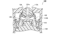
図1は本発明の第1の実施例にかかる自動車の燃料タンクFTの上部に取り付けられる燃料遮断弁10を示す断面図である。燃料遮断弁10は、給油時に燃料タンクFT内の燃料が第1の燃料液位FL1(満タン液位)まで上昇したときに給油ガンをオートストップさせるように作動するとともに、第1の燃料液位FL1を越えて給油して第2の燃料液位FL2(完全閉弁液位)を越えたときに閉じるように作動して外部への燃料の流出を規制するものである。
以下、燃料遮断弁10の各部の構成および作用について説明する。
ケーシング20は、ケーシング本体30と、底支持板35と、蓋体40とを備えている。ケーシング本体30および底支持板35は、耐燃料油性を有した合成樹脂ポリアセタールやナイロンなどから形成されている。蓋体40は、ポリエチレンを主体とする複合材料で形成されている。
弁体機構50は、フロート51と、フロート51の上部に装着されたシート部材55とを備えている。フロート51は、上壁部52と、その上壁部52の外周から下方に形成された筒状の側壁部53とを備えた容器形状に形成されており、その内側スペースが浮力を生じさせるための浮力室51Sになっている。また、フロート51の外周部に上下方向にガイド突条51aが複数形成されている。フロート51の浮力室51S内には、スプリング60が配置されている。スプリング60は、フロート51の一端と底支持板35の上面との間に介在することによりフロート51を上方へ付勢している。
上記弁体通気孔57a、フロート上室55Sおよび通気溝54dは、弁室30Sから第1の接続通路32bに接続される第2の接続通路58を構成している。
次に、燃料遮断弁10の開閉動作について説明する。図1において、燃料タンクFTに燃料が供給されると、燃料タンクFT内の燃料液位の上昇につれて燃料タンクFT内の上部に溜まっていた燃料蒸気は、ケーシング本体30の連通孔33a、弁室30S、第1の接続通路32b、管体通路42aを通じてキャニスタ側へ逃がされる。そして、燃料タンクFT内の燃料液位が所定の第1の燃料液位FL1に達すると、燃料は、底支持板35の連通孔35bを通じて弁室30Sに流入する。これにより、フロート51の浮力およびスプリング60の荷重による上方への力と、フロート51およびシート部材55の自重による下方への力との釣り合いによって、前者が後者を上回ったときにフロート51が上昇して、図5に示すように、シート部材55の第1のシート部56aが第1のシール部32cに着座して第1の接続通路32bの一部を閉じる。
20...ケーシング
30...ケーシング本体
30S...弁室
30a...下開口
32...天井壁部
32a...上部突出部
32b...第1の接続通路
32c...第1のシール部
33...側壁
33a...連通孔
33b...係合穴
33c...フランジ部
35...底支持板
35a...係合爪
35b...連通孔
40...蓋体
41...蓋本体
42...管体部
42a...管体通路
43...フランジ
43a...環状溶着部
44...溶着面
50...弁体機構
51...フロート
51B...フロート
51S...浮力室
51a...ガイド突条
52...上壁部
53...側壁部
54...支持部
54B...支持部
54a...第2のシール部
54Ba...第2のシール部
54b...支持下端部
54d...通気溝
55...シート部材
55B...シート部材
55S...フロート上室
55a...シート面部
55Ba...シート面部
55b...側壁部
55c...取付部
56a...第1のシート部
57a...弁体通気孔
57Ba...弁体通気孔
57b...第2のシート部
57Bb...第2のシート部
58...第2の接続通路
58B...第2の接続通路
60...スプリング
FT...燃料タンク
FL1...第1の燃料液位
FL2...第2の燃料液位
FTa...タンク上壁
FTc...取付穴
Claims (3)
- 燃料タンク(FT)の上部に装着され、該燃料タンク(FT)内と外部とを連通遮断する燃料遮断弁において、
上記燃料タンク(FT)内に連通する弁室(30S)を有するケーシング(20)と、
上記弁室(30S)内に収納され、上記燃料タンク(FT)内の燃料液位に応じて昇降するフロート(51)と、可撓性の材料で形成されかつ上記フロート(51)の上部にフロート上室(55S)を形成するように装着されたシート部材(55)とを有する弁体機構(50)と、
上記弁室(30S)と外部とを接続し、上記フロート(51)の昇降により開閉される接続通路と、
を備え、
上記シート部材(55)は、上記フロート上室(55S)と上記弁室(30S)とを貫通接続する弁体通気孔(57a)を有し、
上記接続通路は、上記ケーシング(20)の上部に設けられ上記弁室(30S)と外部とを接続する第1の接続通路(32b)と、該第1の接続通路(32b)に接続され該第1の接続通路(32b)より通路面積が小さくかつ上記弁体通気孔(57a)および上記フロート上室(55S)を経路とする第2の接続通路(58)とを有し、
上記燃料液位が第1の燃料液位(FL1)まで上昇したときに、上記第2の接続通路(58)を開いた状態に維持するとともに上記シート部材(55)により上記第1の接続通路(32b)が閉じられ、
上記燃料液位が上記第1の燃料液位(FL1)より高い第2の燃料液位(FL2)まで上昇したときに、上記シート部材(55)が弾性変形して上記フロート(51)の上部に密着することで上記第2の接続通路(58)が閉じられること、
を特徴とする燃料遮断弁。 - 請求項1に記載の燃料遮断弁において、
上記第1の接続通路(32b)は、その開口周縁部に第1のシール部(32c)を有し、
上記フロート(51)は、その上部に第2のシール部(54a)を有し、
上記シート部材(55)は、上記弁体通気孔(57a)の上部の開口周縁部に設けられ上記第1のシール部(32c)に着座することで上記第1の接続通路(32b)を閉じる第1のシート部(56a)と、上記弁体通気孔(57a)の下部の開口周縁に設けられ上記第2のシール部(54a)に着座することで上記第2の接続通路(58)を閉じる第2のシート部(57b)とを有する燃料遮断弁。 - 請求項2に記載の燃料遮断弁において、
上記第2のシール部(54Ba)は平面であり、上記第2のシート部(57Bb)は上記弁体通気孔(57Ba)の下部の開口周縁部を囲むように突設されかつ上記第2のシール部(54Ba)に密着する環状突部である燃料遮断弁。
Priority Applications (1)
| Application Number | Priority Date | Filing Date | Title |
|---|---|---|---|
| JP2004169843A JP4301086B2 (ja) | 2004-06-08 | 2004-06-08 | 燃料遮断弁 |
Applications Claiming Priority (1)
| Application Number | Priority Date | Filing Date | Title |
|---|---|---|---|
| JP2004169843A JP4301086B2 (ja) | 2004-06-08 | 2004-06-08 | 燃料遮断弁 |
Publications (2)
| Publication Number | Publication Date |
|---|---|
| JP2005351293A JP2005351293A (ja) | 2005-12-22 |
| JP4301086B2 true JP4301086B2 (ja) | 2009-07-22 |
Family
ID=35585940
Family Applications (1)
| Application Number | Title | Priority Date | Filing Date |
|---|---|---|---|
| JP2004169843A Expired - Fee Related JP4301086B2 (ja) | 2004-06-08 | 2004-06-08 | 燃料遮断弁 |
Country Status (1)
| Country | Link |
|---|---|
| JP (1) | JP4301086B2 (ja) |
Families Citing this family (2)
| Publication number | Priority date | Publication date | Assignee | Title |
|---|---|---|---|---|
| JP5005330B2 (ja) * | 2006-12-15 | 2012-08-22 | 京三電機株式会社 | 燃料流出防止弁 |
| WO2014105453A2 (en) * | 2012-12-24 | 2014-07-03 | Eaton Corporation | Valve assembly for a tank of a vehicle |
-
2004
- 2004-06-08 JP JP2004169843A patent/JP4301086B2/ja not_active Expired - Fee Related
Also Published As
| Publication number | Publication date |
|---|---|
| JP2005351293A (ja) | 2005-12-22 |
Similar Documents
| Publication | Publication Date | Title |
|---|---|---|
| US6591855B2 (en) | Fuel cutoff valve | |
| JP4135664B2 (ja) | 燃料遮断弁 | |
| EP1705051B1 (en) | Low profile overfill limit device with reverse flow capability | |
| JP3931291B2 (ja) | 燃料タンクの燃料流出規制装置 | |
| JP4730218B2 (ja) | 燃料遮断弁 | |
| US8186372B2 (en) | Fuel shut-off valve | |
| JP2006009645A (ja) | 燃料遮断弁 | |
| US6981514B2 (en) | Fuel cutoff valve | |
| US7963296B2 (en) | Fuel cutoff valve | |
| JP2006097674A (ja) | 燃料遮断弁 | |
| US6779545B2 (en) | Pressure control valve for fuel tank | |
| JP4305256B2 (ja) | 燃料遮断弁 | |
| JP4301086B2 (ja) | 燃料遮断弁 | |
| JP4193782B2 (ja) | 燃料遮断弁 | |
| JP2010173397A (ja) | 燃料遮断弁 | |
| JP4518022B2 (ja) | 燃料遮断弁 | |
| JP4487915B2 (ja) | 燃料遮断弁 | |
| JP4635886B2 (ja) | 燃料遮断弁 | |
| JP3988671B2 (ja) | 燃料タンク用バルブ | |
| WO2022215586A1 (ja) | ピラー付き弁装置 | |
| JP4432890B2 (ja) | タンク用流路構造体 | |
| JP5146416B2 (ja) | 燃料遮断弁 | |
| JP2003139002A (ja) | 燃料遮断弁 | |
| JP5315146B2 (ja) | 燃料遮断弁 | |
| JP4506459B2 (ja) | 燃料遮断弁 |
Legal Events
| Date | Code | Title | Description |
|---|---|---|---|
| A621 | Written request for application examination |
Free format text: JAPANESE INTERMEDIATE CODE: A621 Effective date: 20060830 |
|
| TRDD | Decision of grant or rejection written | ||
| A01 | Written decision to grant a patent or to grant a registration (utility model) |
Effective date: 20090331 Free format text: JAPANESE INTERMEDIATE CODE: A01 |
|
| A01 | Written decision to grant a patent or to grant a registration (utility model) |
Free format text: JAPANESE INTERMEDIATE CODE: A01 |
|
| FPAY | Renewal fee payment (prs date is renewal date of database) |
Free format text: PAYMENT UNTIL: 20120501 Year of fee payment: 3 |
|
| R150 | Certificate of patent (=grant) or registration of utility model |
Free format text: JAPANESE INTERMEDIATE CODE: R150 |
|
| A61 | First payment of annual fees (during grant procedure) |
Free format text: JAPANESE INTERMEDIATE CODE: A61 Effective date: 20090413 |
|
| LAPS | Cancellation because of no payment of annual fees |