JP4241241B2 - Hinge structure and electronic equipment - Google Patents
Hinge structure and electronic equipment Download PDFInfo
- Publication number
- JP4241241B2 JP4241241B2 JP2003272742A JP2003272742A JP4241241B2 JP 4241241 B2 JP4241241 B2 JP 4241241B2 JP 2003272742 A JP2003272742 A JP 2003272742A JP 2003272742 A JP2003272742 A JP 2003272742A JP 4241241 B2 JP4241241 B2 JP 4241241B2
- Authority
- JP
- Japan
- Prior art keywords
- housing
- group
- recess
- hinge structure
- recessed part
- Prior art date
- Legal status (The legal status is an assumption and is not a legal conclusion. Google has not performed a legal analysis and makes no representation as to the accuracy of the status listed.)
- Expired - Fee Related
Links
Images


Landscapes
- Hinges (AREA)
- Camera Bodies And Camera Details Or Accessories (AREA)
- Structure And Mechanism Of Cameras (AREA)
- Pivots And Pivotal Connections (AREA)
- Casings For Electric Apparatus (AREA)
- Studio Devices (AREA)
Description
本発明は、ヒンジ構造及びこれを備えた電子機器に関する。 The present invention relates to a hinge structure and an electronic apparatus including the hinge structure.
従来より、ヒンジ構造を介して2筐体を回動可能に連結して構成した折畳式電子機器(例えば、携帯電話機、PHS(R)、PDA、ノート型PC、デジタルカメラ等)が提案され、実用化されている。 Conventionally, a folding electronic device (for example, a mobile phone, a PHS (R), a PDA, a notebook PC, a digital camera, etc.) constructed by connecting two housings through a hinge structure so as to be rotatable is proposed. Has been put to practical use.
従来のヒンジ構造としては、一の筐体と他の筐体とを1つの回動軸を介して回動可能に連結した構造が提案されている。また、近年においては、2つの回動軸を備えた2軸ヒンジ構造が提案されている(例えば、特許文献1参照。)。かかる2軸ヒンジ構造を採用すると、一の筐体を第1の回動軸を中心に180°回動させるとともに、他の筐体を第2の回動軸を中心に反対方向に180°回動させることが可能となり、結果的に、一の筐体に対して他の筐体を360°回動させることができる。
しかし、従来の2軸ヒンジ構造を採用すると、各回動軸を中心に各筐体を別々に回動させる構成を有していたので、各筐体の回動状態がユーザの操作態様によって変化する。このため、筐体の開閉動作が不安定になる場合があった。 However, when the conventional biaxial hinge structure is adopted, each casing is separately rotated around each rotation axis, so that the rotation state of each casing changes depending on the operation mode of the user. . For this reason, the opening / closing operation of the housing may become unstable.
本発明の課題は、筐体の開閉動作の安定化を実現させることができるヒンジ構造を提供することである。 The subject of this invention is providing the hinge structure which can implement | achieve stabilization of the opening / closing operation | movement of a housing | casing.
また、本発明の課題は、前記ヒンジ構造を備えた電子機器を提供することである。 Moreover, the subject of this invention is providing the electronic device provided with the said hinge structure.
以上の課題を解決するため、請求項1に記載の発明は、
例えば図1〜図3及び図7に示すように、
一の筐体(10)を他の筐体(20)に回動可能に連結するヒンジ構造において、
前記一の筐体(10)と前記他の筐体(20)との間に配置されたヒンジ用筐体(30と、
前記ヒンジ用筐体(30)に固定された第1回動軸(31)及び第2回動軸(32)と、
前記一の筐体(10)に設けられて前記第1回動軸(31)を回動自在に支持する第1支持部材(41)と、
前記他の筐体(20)に設けられて前記第2回動軸(32)を回動自在に支持する第2支持部材(42)と、
前記第1回動軸(31)の外周に沿って所定の間隔で複数形成された凹部からなる第1凹部群(51a〜51c)と、
前記第2回動軸(32)の外周に沿って所定の間隔で複数形成された凹部からなる第2凹部群(52a〜52c)と、
前記第1凹部群(51a〜51c)及び前記第2凹部群(52a〜52c)に各々嵌合するように配置された嵌合部材(61、62)と、
前記嵌合部材(61、62)を前記第1凹部群(51a〜51c)又は前記第2凹部群(52a〜52c)に押し付ける弾性部材(71、72)と、を備え、
前記第1凹部群(51a〜51c)を構成する少なくとも一つの凹部(51a)の形状と、前記第2凹部群(52a〜52c)を構成する少なくとも一つの凹部(52a)の形状と、に差が設けられていることを特徴とする。
In order to solve the above problems, the invention described in
For example, as shown in FIGS.
In a hinge structure that pivotally connects one housing (10) to another housing (20),
A hinge housing (30) disposed between the one housing (10) and the other housing (20);
A first rotation shaft (31) and a second rotation shaft (32) fixed to the hinge housing (30);
A first support member (41) provided on the one housing (10) and rotatably supporting the first rotation shaft (31);
A second support member (42) provided on the other casing (20) and rotatably supporting the second rotation shaft (32);
A first recess group (51a to 51c) composed of a plurality of recesses formed at predetermined intervals along the outer periphery of the first rotation shaft (31);
A second recess group (52a to 52c) comprising a plurality of recesses formed at predetermined intervals along the outer periphery of the second rotation shaft (32);
Fitting members (61, 62) arranged to fit in the first recess group (51a-51c) and the second recess group (52a-52c), respectively;
An elastic member (71, 72) for pressing the fitting member (61, 62) against the first recess group (51a-51c) or the second recess group (52a-52c),
Difference between the shape of at least one recess (51a) constituting the first recess group (51a to 51c) and the shape of at least one recess (52a) constituting the second recess group (52a to 52c). Is provided.
請求項1に記載の発明によれば、ヒンジ用筐体に配置・固定された第1回動軸及び第2回動軸が、一の筐体及び他の筐体に設けられた第1支持部及び第2支持部により各々支持される。そして、第1凹部群に嵌合するように配置された嵌合部材が、弾性部材により、ヒンジ用筐体の第1回動軸側に押し付けられて、第1回動軸の外周に沿って所定の間隔で複数形成された第1凹部群に嵌合する。 According to the first aspect of the present invention, the first support shaft and the second support shaft disposed and fixed to the hinge housing have the first support provided in one housing and the other housing. And the second support part. And the fitting member arrange | positioned so that it may fit in a 1st recessed part group is pressed by the 1st rotating shaft side of the housing | casing for hinges with an elastic member, and it follows the outer periphery of a 1st rotating shaft. The plurality of first recesses are formed at a predetermined interval.
このような嵌合部材と第1凹部群との嵌合作用により、一の筐体の回動を所定角度毎に一時的に規制することができる。また、同様に、第2凹部群に嵌合するように配置された嵌合部材が、弾性部材により、ヒンジ用筐体の第2回動軸側に押し付けられて、第2回動軸の外周に形成された第2凹部群に嵌合するので、他の筐体の回動を所定角度毎に一時的に規制することができる。 By such a fitting action between the fitting member and the first recess group, it is possible to temporarily restrict the rotation of one casing at every predetermined angle. Similarly, the fitting member disposed so as to be fitted into the second recess group is pressed against the second rotating shaft side of the hinge housing by the elastic member, and the outer periphery of the second rotating shaft. Since it fits in the 2nd recessed part group formed in this, rotation of another housing | casing can be temporarily controlled for every predetermined angle.
そして、第1凹部群を構成する少なくとも一つの凹部の形状と、第2凹部群を構成する少なくとも一つの凹部の形状と、に差が設けられているため、一の筐体を回動させるために必要な外力(トルク)と、他の筐体を回動させるために必要な外力(トルク)と、に差を設けることができる。この結果、一の筐体と他の筐体との回動の順番を規定することができ、筐体の開閉動作の安定化を実現させることができる。 And since the difference is provided in the shape of the at least 1 recessed part which comprises the 1st recessed part group, and the shape of the at least 1 recessed part which comprises the 2nd recessed part group, in order to rotate one housing | casing A difference can be provided between the external force (torque) necessary for the rotation and the external force (torque) necessary for rotating the other housing. As a result, the turn order of one housing and the other housing can be defined, and the opening / closing operation of the housing can be stabilized.
請求項2に記載の発明は、請求項1に記載のヒンジ構造であって、
例えば図7に示すように、
前記第1凹部群(51a〜51c)を構成する少なくとも一つの凹部(51a)の開口角度と、前記第2凹部群(52a〜52c)を構成する少なくとも一つの前記凹部(52a)の開口角度と、に差が設けられていることを特徴とする。
The invention according to claim 2 is the hinge structure according to
For example, as shown in FIG.
An opening angle of at least one recess (51a) constituting the first recess group (51a to 51c) and an opening angle of at least one recess (52a) constituting the second recess group (52a to 52c); Are provided with a difference.
請求項3に記載の発明は、請求項1又は2に記載のヒンジ構造であって、
例えば図8(a)、(b)に示すように、
前記第1凹部群(51d〜51f)を構成する少なくとも一つの凹部(51e)の断面形状と、前記第2凹部群(52d〜52f)を構成する少なくとも一つの凹部(52e)の断面形状と、に差が設けられていることを特徴とする。
Invention of Claim 3 is the hinge structure of
For example, as shown in FIGS. 8A and 8B,
A cross-sectional shape of at least one recess (51e) constituting the first recess group (51d to 51f), and a cross-sectional shape of at least one recess (52e) constituting the second recess group (52d to 52f); Is characterized in that a difference is provided.
請求項4に記載の発明は、請求項1から3の何れか一項に記載のヒンジ構造であって、
例えば図8(c)に示すように、
前記第1凹部群又は前記第2凹部群(52g〜52i)を各々構成する複数の凹部の一つ(52h)の形状は、他の一つの凹部(52g)の形状と異なっていることを特徴とする。
Invention of Claim 4 is the hinge structure as described in any one of
For example, as shown in FIG.
The shape of one of the plurality of recesses (52h) constituting each of the first recess group or the second recess group (52g to 52i) is different from the shape of the other recess (52g). And
請求項5に記載の発明は、請求項1から4の何れか一項に記載のヒンジ構造であって、
例えば図4及び図7に示すように、
前記第1凹部群(51a〜51c)を構成する少なくとも一つの凹部(51a)又は前記第2凹部群を構成する少なくとも一つの凹部は、これら凹部(51a)に前記嵌合部材(61)を嵌合させて前記一の筐体(10)及び前記他の筐体(20)を閉状態にした際に、前記一の筐体(10)と前記他の筐体(20)とを相互に近接させる方向に付勢するような位置に設けられていることを特徴とする。
Invention of
For example, as shown in FIGS.
At least one recess (51a) that constitutes the first recess group (51a to 51c) or at least one recess that constitutes the second recess group fits the fitting member (61) into the recess (51a). When the one casing (10) and the other casing (20) are closed, the one casing (10) and the other casing (20) are close to each other. It is provided in the position which is urged | biased in the direction to make.
請求項6に記載の発明は、請求項1から5の何れか一項に記載のヒンジ構造であって、
例えば図7に示すように、
前記嵌合部材(61、62)は、
球状の部材であることを特徴とする。
Invention of
For example, as shown in FIG.
The fitting members (61, 62) are
It is a spherical member.
請求項7に記載の発明は、請求項1から6の何れか一項に記載のヒンジ構造であって、
例えば図1〜図3に示すように、
前記第1回動軸(31)及び前記第2回動軸(32)は、
前記一の筐体(10)と前記他の筐体(20)との間に配線されるケーブル(80)を通すための挿通孔(31a、32a)を有することを特徴とする。
The invention according to claim 7 is the hinge structure according to any one of
For example, as shown in FIGS.
The first rotation axis (31) and the second rotation axis (32) are:
It has an insertion hole (31a, 32a) for passing a cable (80) wired between the one casing (10) and the other casing (20).
請求項7に記載の発明によれば、一の筐体と他の筐体との間に配線されるケーブルを、第1回動軸及び第2回動軸に設けられた挿入孔に通すことができる。この結果、一の筐体に対して他の筐体を回動させた際に、ケーブルが露出するのを阻止することができる。 According to the seventh aspect of the present invention, the cable wired between the one housing and the other housing is passed through the insertion holes provided in the first rotating shaft and the second rotating shaft. Can do. As a result, it is possible to prevent the cable from being exposed when the other casing is rotated with respect to the one casing.
請求項8に記載の発明は、電子機器(1)であって、
例えば図1に示すように、
撮像部(11)を備える一の筐体(10)と、表示部(21)を備える他の筐体(20)と、が請求項1から7の何れか一項に記載のヒンジ構造を介して回動可能に連結されてなることを特徴とする。
Invention of
For example, as shown in FIG.
The one housing (10) including the imaging unit (11) and the other housing (20) including the display unit (21) are arranged via the hinge structure according to any one of
請求項8に記載の発明によれば、撮像部を備える一の筐体と、表示部を備える他の筐体と、が請求項1から7の何れか一項に記載のヒンジ構造を介して回動可能に連結されている。このため、ヒンジ構造を介して2筐体を回動させて一の筐体の一面と他の筐体の一面とを対向させることができるので、これら対向する一の筐体の一面に撮像部を設けるとともに、他の筐体の一面に表示部を設けることにより、撮像部及び表示部の損傷を防ぐことができる。また、前記したように撮像部と表示部とを対向させた状態から、ヒンジ構造を介して2筐体を相互に反対方向に180°回動させることにより、撮像部及び表示部を反対向きに露出させることができ、撮像部及び表示部を用いて撮像を行うことができる。
According to the invention described in
本発明によれば、筐体の開閉動作の安定化を実現させることができるヒンジ構造を得ることができる。 ADVANTAGE OF THE INVENTION According to this invention, the hinge structure which can implement | achieve stabilization of the opening / closing operation | movement of a housing | casing can be obtained.
また、本発明によれば、前記ヒンジ構造を備えた電子機器を得ることができる。 Moreover, according to this invention, the electronic device provided with the said hinge structure can be obtained.
以下、図を参照して本発明の実施の形態について詳細に説明する。なお、本発明に係る電子機器の例として、実施形態1においては「デジタルカメラ」を、実施形態2においては「カメラ付携帯電話機」を、各々挙げて説明することとする。また、以下の各実施形態においては、本発明に係るヒンジ構造の例として「2軸ヒンジ構造」を採用している。 Hereinafter, embodiments of the present invention will be described in detail with reference to the drawings. As examples of the electronic apparatus according to the present invention, “digital camera” in the first embodiment and “camera-equipped mobile phone” in the second embodiment will be described. In the following embodiments, a “biaxial hinge structure” is employed as an example of the hinge structure according to the present invention.
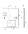
(実施形態1)
まず、本発明の実施形態1に係るデジタルカメラ1の全体構成について、図1〜図6を用いて説明する。図1は開かれた状態にあるデジタルカメラ1の平面図、図2は図1のII部分の拡大図、図3(a)は図1のA−A部分の断面図、図3(b)はB−B部分の断面図、図3(c)はC−C部分の断面図である。
(Embodiment 1)
First, the overall configuration of the
また、図4(a)は、デジタルカメラ1の第1筐体10の内側面と第2筐体20の内側面とを対向させた状態(以下、「携行状態」という)を示す正面図であり、図4(b)はその側面図である。図5(a)は、図3の携行状態から第1筐体10及び第2筐体20を回動させて開いた状態を示す正面図であり、図5(b)はその側面図である。図6(a)は、第1筐体10の外側面と第2筐体20の外側面とを対向させた状態(以下、「撮像状態」という)を示す正面図であり、図6(b)はその側面図である。
4A is a front view showing a state (hereinafter referred to as “carrying state”) in which the inner surface of the
デジタルカメラ1は、撮像部11等を備えた第1筐体10、表示部21等を備えた第2筐体20、これら第1筐体10と第2筐体20とを回動可能に連結する2軸ヒンジ構造、第1筐体10内の電子部品と第2筐体20内の電子部品とを電気的に接続するためのケーブル80、等を備えて構成されている。なお、図1においては、第1筐体10に設けられる撮像部11と、第2筐体20に設けられる表示部21と、を点線で示している。
The
第1筐体10は、アルミニウムやステンレス等の金属材料で構成された薄型の筐体であり、略直方体形状を呈している。第1筐体10には、レンズやCCD等で構成される撮像部11、暗部撮像時に被写体に光を照射するストロボ発光部、自動撮像時に撮像のタイミングを報知するセルフタイマランプ、デジタルカメラ1全体を統合制御する制御部、等が搭載される。なお、ストロボ発光部、セルフタイマランプ及び制御部については、図示を省略している。
The
制御部は、デジタルカメラ1全体を統合制御するCPU、各種制御プログラム等を記録したROM、画像情報を一時的に保存するとともに制御プログラムを一時的に展開させるためのワークエリアとして機能するRAM、等を備えている。制御部には、撮像部11が電気的に接続されている。また、制御部は、ケーブル80を介して第2筐体20の表示部21や操作部に電気的に接続されている。第2筐体20の操作部の操作信号を受けた制御部は、撮像部11を駆動制御して所定の撮像動作を実現させる。
The control unit includes a CPU that controls the entire
第2筐体20は、アルミニウムやステンレス等の金属材料で構成された薄型の筐体であり、略直方体形状を呈している。第2筐体20には、被写体の静止画像情報や動画像情報を表示する表示部21、モード選択等を行うための機能キー等から構成される操作部、ファインダ接眼部、等が搭載される。また、2軸ヒンジ構造を構成するヒンジ用筐体30には、撮像時に用いるシャッタボタン90(図5参照)が設けられている。表示部21や操作部やシャッタボタン90は、ケーブル80を介して第1筐体10内の制御部に電気的に接続されており、この制御部のCPUによって制御される。なお、操作部及びファインダ接眼部については、図示を省略している。
The
2軸ヒンジ構造は、ヒンジ用筐体30、このヒンジ用筐体30に固定された第1・第2回動軸31、32、第1・第2回動軸31、32を回動自在に支持する第1・第2支持部41、42、第1・第2回動軸31、32に形成された複数の凹部、これら凹部に嵌合するスチールボール61、62、スチールボール61、62を第1・第2回動軸31、32側に押し付ける板バネ71、72、等を備えて構成されている(図1〜図3参照)。
In the biaxial hinge structure, the
第1筐体10は、ヒンジ用筐体30の第1回動軸31を中心に回動可能とされている。そして、第1回動軸31に形成された複数の凹部に、板バネ71によって凹部側に押し付けられたスチールボール61が嵌合することにより、第1筐体10の回動が所定角度毎に一時的に規制される。また、第2筐体20は、ヒンジ用筐体30の第2回動軸32を中心に回動可能とされている。そして、第2回動軸32に形成された複数の凹部に、板バネ72によって凹部側に押し付けられたスチールボール62が嵌合することにより、第2筐体20の回動が所定角度毎に一時的に規制される。なお、2軸ヒンジ構造の構成の詳細については、図1〜図3及び図7を用いて後述する。
The
携行状態(図4参照)にあるデジタルカメラ1に、第1筐体10と第2筐体20とを離隔させるような外力を作用させると、その外力により、第1筐体10が第1回動軸31を中心に回動するとともに、第2筐体20が第2回動軸32を中心に第1筐体10と反対方向に回動する。図5は、第1筐体10及び第2筐体20が、図3の携行状態から矢印A及び矢印Bの方向に各々90°回動した状態を示している。図6は、第1筐体10及び第2筐体20が、図3の携行状態から矢印A及び矢印Bの方向に各々180°回動した状態を示している。
When an external force that separates the
デジタルカメラ1の携行時においては、第1筐体10の内側面と第2筐体20の内側面とを対向させて、撮像部11や表示部21を内部に収納することができる(図4参照)。一方、デジタルカメラ1を用いて撮像を行う時には、第1筐体10の外側面と第2筐体20の外側面とを対向させて、撮像部11や表示部21を露出させることができる(図6参照)。
When the
次に、図1〜図3及び図7を用いて、デジタルカメラ1の2軸ヒンジ構造の構成について詳細に説明する。図7は、2軸ヒンジ構造の拡大断面図(図3(c)の拡大図)である。
Next, the configuration of the biaxial hinge structure of the
2軸ヒンジ構造のヒンジ用筐体30は、第1筐体10と第2筐体20との間に配置される長尺狭幅の略直方体形状の筐体であり、アルミニウムやステンレス等の金属材料で構成されている(図1参照)。
The
第1回動軸31は、第1筐体10側に配置された状態でヒンジ用筐体30の長手方向両端部に固定された円筒体である。第2回動軸32は、第2筐体20側に配置された状態でヒンジ用筐体30の長手方向両端部に固定された円筒体である。これら第1回動軸31及び第2回動軸32には、ケーブル80を通すための挿通孔31a、32aが設けられている(図1〜図3参照)。なお、第1回動軸31及び第2回動軸32は、ヒンジ用筐体30に回り止めのピン33で固定されている。
The
第1回動軸31の長手方向端部近傍の外周部分には、周方向に沿って略90°毎に3つの凹部51a〜51cが形成されている。これら凹部51a〜51cの形状は略円錐形状とされている。そして、凹部51a及び凹部51cの開口角度は120°に設定されており、凹部51bの開口角度は90°に設定されている(図7参照)。これら凹部51a〜51cにより、本発明における第1凹部群が構成される。
Three
一方、第2回動軸32の長手方向端部近傍の外周部分には、周方向に沿って略90°毎に3つの凹部52a〜52cが形成されている。これら凹部52a〜52cの形状は略円錐形状とされており、各々の開口角度は90°に設定されている(図7参照)。これら凹部52a〜52cにより、本発明における第2凹部群が構成される。
On the other hand, three
図4の携行状態は、第1凹部群の凹部51aにスチールボール61を嵌合させるとともに、第2凹部群の凹部52aにスチールボール62を嵌合させた状態である。また、図5の状態(携行状態から第1筐体10及び第2筐体20を各々反対方向に90°回動させた状態)は、第1凹部群の凹部51bにスチールボール61を嵌合させるとともに、第2凹部群の凹部52bにスチールボール62を嵌合させた状態である。また、図6の撮像状態は、第1凹部群の凹部51cにスチールボール61を嵌合させるとともに、第2凹部群の凹部52cにスチールボール62を嵌合させた状態である。
The carrying state of FIG. 4 is a state in which the
第1凹部群の凹部51aは、やや第2凹部群寄り(第2筐体20寄り)の位置に設けられているため、凹部51aの中心線S1は、第2凹部群の凹部52aの中心線S2と平行ではなく、やや第2凹部群側(第2筐体20側)に傾斜している(図7参照)。このため、第1凹部群の凹部51aにスチールボール61を嵌合させるとともに第2凹部群の凹部52aにスチールボール62を嵌合させて、図4の携行状態(閉状態)にすると、第1筐体10は第2筐体20側に近接する方向に付勢されることとなる。
同様に、第1凹部群の凹部51cは、やや第2凹部群寄り(第2筐体20寄り)の位置に設けられているため、凹部51cの中心線S1は、第2凹部群の凹部52aの中心線S2と平行ではなく、やや第2凹部群側(第2筐体20側)に傾斜している(図7参照)。このため、第1凹部群の凹部51cにスチールボール61を嵌合させるとともに第2凹部群の凹部52cにスチールボール62を嵌合させて、図6の撮像状態(閉状態)にすると、第1筐体10は第2筐体20側に近接する方向に付勢されることとなる。
Similarly, the
すなわち、第1凹部群の凹部51a及び凹部51cは、第1筐体10及び第2筐体20を閉状態(図4の携行状態及び図6の撮像状態)にした際に第1筐体10を第2筐体20に近接させる方向に付勢するような位置に設けられている。
That is, the
なお、第2凹部群の凹部52a及び凹部52cをやや第1凹部群寄り(第1筐体10寄り)の位置に設けることもできる。かかる場合には、第1筐体10及び第2筐体20を閉状態(図4の携行状態及び図6の撮像状態)にした際に第2筐体20を第1筐体10に近接させる方向に付勢することができる。
In addition, the recessed
第1支持部材41は、第1筐体10のヒンジ用筐体30側の端部にネジ40で固定される長尺部材であり、第1回動軸31を回動自在に支持する(図2参照)。第1支持部材41の内側(第1筐体10側)の面には、長手方向に沿って断面矩形状の長尺溝41aが設けられており、この長尺溝41aに板バネ71が嵌め込まれている(図3及び図7参照)。
The
板バネ71は、本発明における弾性部材であり、その長手方向中央近傍部分の2箇所が第1支持部材41にネジ70で固定されている(図2参照)。また、板バネ71の両端には、第1回動軸31側に突出してスチールボール61に当接する突出部71aが設けられている(図7参照)。第1支持部材41の長尺溝41aの一部には、スチールボール61と略同一径を有する貫通孔41bが設けられている。
The
スチールボール61は、金属製の球体であり、第1支持部材41の貫通孔41cに摺動可能に嵌め込まれた状態で板バネ71の突出部71aに当接し、板バネ71の弾性力により第1回動軸31側に押し付けられて、第1凹部群(凹部51a〜51c)に嵌めこまれる(図7参照)。スチールボール61は、本発明における嵌合部材である。嵌合部材としては、金属製の球体に限らず、合成樹脂等で調製した球体を採用することもできる。また、嵌合部材の形状は球状に限られるものではなく、凹部の形状に合わせて適宜決めることができる。
The
第2支持部材42は、第2筐体20のヒンジ用筐体30側の端部にネジ40で固定される長尺部材であり、第2回動軸32を回動自在に支持する(図2参照)。第2支持部材42の内側(第2筐体20側)の面には、長手方向に沿って断面矩形状の長尺溝42aが設けられており、この長尺溝42aに板バネ72が嵌め込まれている(図3及び図7参照)。
The
板バネ72は、本発明における弾性部材であり、その長手方向中央近傍部分の2箇所は、第2支持部材42にネジ70で固定されている(図2参照)。また、板バネ72の両端には、第2回動軸32側に突出してスチールボール62に当接する突出部72aが設けられている(図7参照)。第2支持部材42の長尺溝42aの一部には、スチールボール62と略同一径を有する貫通孔42bが設けられている。
The
スチールボール62は、金属製の球体であり、第1支持部材42の貫通孔42bに摺動可能に嵌め込まれた状態で板バネ72の突出部72aに当接し、板バネ72の弾性力により第2回動軸32側に押し付けられて、第2凹部群(凹部52a〜52c)に嵌めこまれる(図7参照)。スチールボール62は、スチールボール61と同様に、本発明における嵌合部材である。
The
以上説明した実施形態1に係るデジタルカメラ1の2軸ヒンジ構造においては、ヒンジ用筐体30に配置・固定された第1回動軸31及び第2回動軸32が、第1筐体10及び第2筐体20に設けられた第1支持部材41及び第2支持部材42により各々支持される。そして、第1筐体10の第1支持部材41内に配置されたスチールボール61が、板バネ71により第1回動軸31側に押し付けられて、第1回動軸31の外周に沿って所定の間隔で複数形成された第1凹部群(凹部51a〜51c)に嵌合する。
In the two-axis hinge structure of the
このようなスチールボール61と第1凹部群との嵌合作用により、第1筐体10の回動を所定角度毎に一時的に規制することができる。また、同様に、第2筐体20の第2支持部材42内に配置されたスチールボール62が、板バネ72により第2回動軸32側に押し付けられて、第2回動軸32の外周に形成された第2凹部群(凹部52a〜52c)に嵌合するので、第2筐体10の回動を所定角度毎に一時的に規制することができる。
By such a fitting action between the
そして、第1凹部群を構成する凹部51a、51cの開口角度と、第2凹部群を構成する凹部52a、52cの開口角度と、に差が設けられているため、第1筐体10を回動させるために必要な外力と、第2筐体20を回動させるために必要な外力と、に差を設けることができる。
Since there is a difference between the opening angle of the
すなわち、第1凹部群を構成する凹部51aの開口角度(120°)は、第2凹部群を構成する凹部52aの開口角度(90°)より広いため、第1筐体10を回動させるために必要な外力は、第2筐体20を回動させるために必要な外力より小さくなる。従って、図3の携行状態にあるデジタルカメラ1に、第1筐体10と第2筐体20とを離隔させるような外力を作用させると、第1筐体10が第2筐体20よりも先に回動を開始することとなる。
That is, since the opening angle (120 °) of the
一方、第1凹部群を構成する凹部51cの開口角度(120°)は、第2凹部群を構成する凹部52cの開口角度(90°)より広いため、図5の撮像状態にあるデジタルカメラ1に、第1筐体10と第2筐体20とを離隔させるような外力を作用させた場合においても、第1筐体10が第2筐体20よりも先に回動を開始することとなる。
On the other hand, since the opening angle (120 °) of the
従って、第1筐体10と第2筐体20との回動の順番を規定することができ、筐体の開閉動作の安定化を実現させることができる。
Therefore, the turn order of the
また、第1凹部群及び第2凹部群を構成する凹部は略円錐形状とされているため、第1筐体10(第2筐体20)と一体的に第1支持部材41(第2支持部材42)及びスチールボール61(62)が回動して、スチールボール61(62)が凹部の近傍に達すると、スチールボール61(62)が凹部内に吸い込まれるようにスライドして嵌合する。 Moreover, since the recessed part which comprises a 1st recessed part group and a 2nd recessed part group is substantially conical shape, it is integrated with the 1st housing | casing 10 (2nd housing | casing 20), and the 1st support member 41 (2nd support). When the member 42) and the steel ball 61 (62) rotate and the steel ball 61 (62) reaches the vicinity of the recess, the steel ball 61 (62) is slid and fitted so as to be sucked into the recess. .
例えば、図5の状態から図4の携行状態(又は図6の撮像状態)に移行させるために、第1筐体10及び第2筐体20を回動させて、スチールボール61、62を凹部51a(51c)、52a(52c)近傍に位置させると、これらスチールボール61、62が凹部51a(51c)、52a(52c)内に吸い込まれるようにスライドして嵌合する。この結果、図4の携行状態(又は図6の撮像状態)に迅速かつ確実に移行させることができる。
For example, in order to shift from the state of FIG. 5 to the carrying state of FIG. 4 (or the imaging state of FIG. 6), the
また、第1凹部群及び第2凹部群を構成する凹部は略円錐形状とされているため、凹部に嵌合されたスチールボール61、62は、一定の外力を加えない限り凹部から抜けることがない。このため、図4の携行状態や図6の撮像状態を安定的に保持することができる。
Moreover, since the recessed part which comprises a 1st recessed part group and a 2nd recessed part group is made into the substantially conical shape, the
さらに、第1凹部群の凹部51a及び凹部51cは、やや第2凹部群寄り(第2筐体20寄り)の位置に設けられているので、第1筐体10及び第2筐体20を閉状態(図4の携行状態及び図6の撮像状態)にした際に、第1筐体10を第2筐体20に近接させる方向に付勢することができる。
Furthermore, since the
また、第1筐体10と第2筐体20との間に配線されるケーブル80を、第1回動軸31及び第2回動軸32に設けられた挿通孔31a、32aに通すことができるので、第1筐体10に対して第2筐体20を360°回動させた際に、ケーブル80が露出するのを阻止することができる(図1参照)。
Further, the
また、以上説明した実施形態1に係るデジタルカメラ1においては、撮像部11を備える第1筐体10と、表示部21を備える第2筐体20と、が2軸ヒンジ構造を介して回動可能に連結されている(図1参照)。このため、2軸ヒンジ構造を介して2筐体10、20を回動させて、撮像部11が設けられた第1筐体10の内側面と、表示部21が設けられた第2筐体20の内側面と、を対向させることができる(図4参照)。従って、撮像部11及び表示部21の損傷を防ぐことができる。また、図4に示した携行状態から、2軸ヒンジ構造30を介して2筐体10、20を相互に反対方向に180°回動させることにより、撮像部11及び表示部21を反対向きに露出させることができる(図6参照)。そして、これら撮像部11及び表示部21を用いて撮像を行うことができる。
In the
なお、以上の実施形態1においては、「略円錐形状」の凹部を採用した例を示したが、図8(a)に示すような「お椀型形状」の凹部51d〜51fを採用することもできる。この際、図8(a)に示したように凹部51d及び51fの深さと、凹部51eの深さと、に差を設けてもよい。
In the above-described first embodiment, an example in which the “substantially conical shape” concave portion is employed has been described. However, “basket-shaped”
また、以上の実施形態1においては、第1凹部群を構成する凹部の断面形状と、第2凹部群を構成する凹部の断面形状と、を略同一の形状(扇形状)にしたが、図8(a)、(b)に示すように、第1凹部群を構成する一の凹部51eの断面形状と、第2凹部群を構成する一の凹部52eの断面形状と、に差を設けることもできる。
In
また、以上の実施形態1においては、第1凹部群及び第2凹部群を各々構成する複数の凹部の形状を略同一の形状(略円錐形状)にしたが、図8(c)に示すように、第1凹部群又は第2凹部群を各々構成する複数の凹部の一つ(52h)の形状を、他の凹部(52g、52i)の形状と異ならせることもできる。
Moreover, in the
(実施形態2)
次に、本発明の実施形態2に係るカメラ付携帯電話機1Aについて、図9を用いて説明する。図9は、開かれた状態にあるカメラ付携帯電話機1Aの平面図である。
(Embodiment 2)
Next, a camera-equipped
カメラ付携帯電話機1Aは、表示部10B等を備えた第1筐体10A、撮像部20B及び操作部20C等を備えた第2筐体20A、これら第1筐体10Aと第2筐体20Aとを回動可能に連結する2軸ヒンジ構造、第1筐体10A内の部品と第2筐体20A内の部品とを電気的に接続するための(図示されていない)ケーブル、等を備えて構成されている。なお、第1筐体10Aは本発明における「他の筐体」であり、第2筐体20Aは本発明における「一の筐体」である。
The camera-equipped
第1筐体10Aには、被写体の静止画像情報や動画像情報を表示する表示部10B、スピーカ10C等が搭載されている。第2筐体20Aには、レンズやCCD等で構成される撮像部20B、十字キーやテンキー等から構成される操作部20C、マイク20D、携帯電話機1A全体を統合制御する(図示されていない)制御部、等が搭載されている。制御部には、撮像部20Bや操作部20Cが電気的に接続されている。また、制御部は、ケーブルを介して第1筐体10Aの表示部10Bに電気的に接続されている。
The
2軸ヒンジ構造は、ヒンジ用筐体、第1・第2回動軸、第1・第2支持部、第1・第2凹部群、スチールボール、板バネ、等を備えており、その構成は、実施例1における2軸ヒンジ構造(図1〜図3及び図7参照)と実質的に同一である。このため、実施例1と同様の効果を得ることができる。 The biaxial hinge structure includes a hinge housing, first and second pivot shafts, first and second support portions, first and second recess groups, steel balls, leaf springs, and the like. These are substantially the same as the biaxial hinge structure in Embodiment 1 (see FIGS. 1 to 3 and 7). For this reason, the same effect as Example 1 can be acquired.
なお、以上の実施形態においては、本発明をデジタルカメラ1及びカメラ付携帯電話機1Aに適用した例を示したが、他の折畳式電子機器(例えば、折畳式のカメラ付PHS(R)や折畳式のカメラ付PDA等)に本発明を適用することもできる。
In the above embodiment, the example in which the present invention is applied to the
1 デジタルカメラ(電子機器)
1A カメラ付携帯電話機(電子機器)
10 第1筐体(一の筐体)
11 撮像部
10A 第1筐体(他の筐体)
10B 表示部
20 第2筐体(他の筐体)
21 表示部
20A 第2筐体(一の筐体)
20B 撮像部
30 ヒンジ用筐体
31 第1回動軸
31a 挿通孔
32 第2回動軸
32a 挿通孔
41 第1支持部材
42 第2支持部材
51a〜51c 第1凹部群
52a〜52c 第2凹部群
61、62 スチールボール(嵌合部材)
71、72 板バネ(弾性部材)
80 ケーブル
1 Digital camera (electronic equipment)
1A Mobile phone with camera (electronic equipment)
10 First housing (one housing)
11
21
20B
71, 72 Leaf spring (elastic member)
80 cables
Claims (8)
前記一の筐体と前記他の筐体との間に配置されたヒンジ用筐体と、
前記ヒンジ用筐体に固定された第1回動軸及び第2回動軸と、
前記一の筐体に設けられて前記第1回動軸を回動自在に支持する第1支持部材と、
前記他の筐体に設けられて前記第2回動軸を回動自在に支持する第2支持部材と、
前記第1回動軸の外周に沿って所定の間隔で複数形成された凹部からなる第1凹部群と、
前記第2回動軸の外周に沿って所定の間隔で複数形成された凹部からなる第2凹部群と、
前記第1凹部群及び前記第2凹部群に各々嵌合するように配置された嵌合部材と、
前記嵌合部材を前記第1凹部群又は前記第2凹部群に押し付ける弾性部材と、を備え、
前記第1凹部群を構成する少なくとも一つの凹部の形状と、前記第2凹部群を構成する少なくとも一つの凹部の形状と、に差が設けられていることを特徴とするヒンジ構造。 In a hinge structure that pivotally connects one housing to another housing,
A hinge housing disposed between the one housing and the other housing;
A first rotation shaft and a second rotation shaft fixed to the hinge housing;
A first support member provided in the one housing and rotatably supporting the first rotation shaft;
A second support member provided in the other casing and rotatably supporting the second rotation shaft;
A first recess group comprising a plurality of recesses formed at predetermined intervals along the outer periphery of the first rotation shaft;
A second recess group comprising a plurality of recesses formed at predetermined intervals along the outer periphery of the second rotation shaft;
A fitting member disposed so as to be fitted to each of the first recess group and the second recess group;
An elastic member that presses the fitting member against the first recess group or the second recess group,
A hinge structure characterized in that a difference is provided between the shape of at least one concave portion constituting the first concave portion group and the shape of at least one concave portion constituting the second concave portion group.
球状の部材であることを特徴とする請求項1から5の何れか一項に記載のヒンジ構造。 The fitting member is
It is a spherical member, The hinge structure as described in any one of Claim 1 to 5 characterized by the above-mentioned.
前記一の筐体と前記他の筐体との間に配線されるケーブルを通すための挿通孔を有することを特徴とする請求項1から6の何れか一項に記載のヒンジ構造。 The first rotation axis and the second rotation axis are:
The hinge structure according to any one of claims 1 to 6, further comprising an insertion hole for passing a cable wired between the one housing and the other housing.
Priority Applications (1)
| Application Number | Priority Date | Filing Date | Title |
|---|---|---|---|
| JP2003272742A JP4241241B2 (en) | 2003-07-10 | 2003-07-10 | Hinge structure and electronic equipment |
Applications Claiming Priority (1)
| Application Number | Priority Date | Filing Date | Title |
|---|---|---|---|
| JP2003272742A JP4241241B2 (en) | 2003-07-10 | 2003-07-10 | Hinge structure and electronic equipment |
Publications (2)
| Publication Number | Publication Date |
|---|---|
| JP2005030542A JP2005030542A (en) | 2005-02-03 |
| JP4241241B2 true JP4241241B2 (en) | 2009-03-18 |
Family
ID=34210202
Family Applications (1)
| Application Number | Title | Priority Date | Filing Date |
|---|---|---|---|
| JP2003272742A Expired - Fee Related JP4241241B2 (en) | 2003-07-10 | 2003-07-10 | Hinge structure and electronic equipment |
Country Status (1)
| Country | Link |
|---|---|
| JP (1) | JP4241241B2 (en) |
Families Citing this family (14)
| Publication number | Priority date | Publication date | Assignee | Title |
|---|---|---|---|---|
| JP4575185B2 (en) * | 2005-02-15 | 2010-11-04 | 株式会社東芝 | Electronics |
| JP2006283836A (en) * | 2005-03-31 | 2006-10-19 | Omron Corp | Link mechanism and mobile terminal |
| JP2007107592A (en) * | 2005-10-12 | 2007-04-26 | Strawberry Corporation | Hinge device and electronic apparatus using hinge device |
| JP4568242B2 (en) * | 2006-03-15 | 2010-10-27 | スガツネ工業株式会社 | Biaxial hinge device and portable device |
| JP4966095B2 (en) * | 2007-05-28 | 2012-07-04 | 株式会社テラモト | Hinge mechanism |
| KR100899711B1 (en) | 2007-09-07 | 2009-05-28 | 주식회사 피플웍스 | Wiring Fixture for Enclosure |
| WO2010100843A1 (en) * | 2009-03-03 | 2010-09-10 | 日本電気株式会社 | Two-axis hinge and electronic applaiance |
| JP4960480B2 (en) * | 2010-06-18 | 2012-06-27 | 株式会社東芝 | Electronics |
| JP2012053832A (en) * | 2010-09-03 | 2012-03-15 | Nec Corp | Information processing terminal |
| KR101797241B1 (en) * | 2011-03-02 | 2017-11-13 | 삼성전자주식회사 | Slim-type cradle for mobile phone |
| CN105306643A (en) * | 2015-11-30 | 2016-02-03 | 天津德铃通信部品有限公司 | Twin rotary shaft hinge structure and electronic device |
| CN108552609B (en) * | 2018-06-29 | 2024-09-24 | 深圳市合元科技有限公司 | Electronic cigarette |
| JP6824546B1 (en) * | 2020-06-09 | 2021-02-03 | グローバルアーク株式会社 | Hinge and door mechanism |
| CN113163086B (en) * | 2021-04-07 | 2023-04-07 | 惠州Tcl云创科技有限公司 | Be applied to display device's intelligence and shoot accessory structure |
Family Cites Families (11)
| Publication number | Priority date | Publication date | Assignee | Title |
|---|---|---|---|---|
| JPH0710093Y2 (en) * | 1989-10-24 | 1995-03-08 | 株式会社ニフコ | Hinge device for rotating body and electronic device using the device as a display device |
| JPH0822343A (en) * | 1994-07-07 | 1996-01-23 | Olympus Optical Co Ltd | Information processor |
| JP2592409B2 (en) * | 1994-07-27 | 1997-03-19 | タキゲン製造株式会社 | Biaxial hinge |
| US5666694A (en) * | 1995-09-28 | 1997-09-16 | Hewlett-Packard Company | Hinge arrangement |
| JPH10102878A (en) * | 1996-09-27 | 1998-04-21 | Oi Seisakusho Co Ltd | Hinge device and cabinet using the same |
| JPH10161773A (en) * | 1996-12-02 | 1998-06-19 | Fujitsu Ltd | Portable information processing device |
| JPH1153059A (en) * | 1997-07-30 | 1999-02-26 | Canon Inc | Electronic equipment |
| JP2000320226A (en) * | 1999-05-14 | 2000-11-21 | Atom Livin Tech Co Ltd | Double hinge |
| US6493216B1 (en) * | 1999-10-20 | 2002-12-10 | Arima Computer Corp. | Portable computer with an LCD which can be rotated within 360 degrees |
| JP3762876B2 (en) * | 2001-04-02 | 2006-04-05 | スガツネ工業株式会社 | Foldable mobile phone |
| JP2003189142A (en) * | 2001-12-14 | 2003-07-04 | Ito Denshi Kogyo Kk | Imaging unit and electronic equipment |
-
2003
- 2003-07-10 JP JP2003272742A patent/JP4241241B2/en not_active Expired - Fee Related
Also Published As
| Publication number | Publication date |
|---|---|
| JP2005030542A (en) | 2005-02-03 |
Similar Documents
| Publication | Publication Date | Title |
|---|---|---|
| KR100539527B1 (en) | Portable Telephone with Camera | |
| JP4241241B2 (en) | Hinge structure and electronic equipment | |
| KR100449451B1 (en) | Camera lens mounting device of folder type telephone | |
| KR100982997B1 (en) | Portable terminal for folder | |
| JP4188810B2 (en) | Mobile device with camera | |
| US7526325B2 (en) | Triple-axis rotation folder-type portable apparatus | |
| JP2005023955A (en) | Hinge structure, image pickup device and cellular phone device | |
| JP2004187186A (en) | Foldable portable device and hinge mechanism thereof | |
| KR20030057661A (en) | Portable phone with camera lenz opening means in closed folder | |
| JP2003008953A (en) | Information terminal having camera with rotary function | |
| KR20050049232A (en) | Mobile device | |
| KR20050002460A (en) | Hinge device for portable terminal with sub housing stopper | |
| EP1843589B1 (en) | Camera lens assembly for portable wireless terminals | |
| EP1489835B1 (en) | Foldable portable instrument with camera | |
| JP3874750B2 (en) | Foldable mobile terminal with slide function | |
| KR100671694B1 (en) | Mobile communication terminal with swivel hinge mechanism | |
| JP4125192B2 (en) | Mobile terminal device | |
| KR100849295B1 (en) | Camera lens assembly in portable wireless terminal | |
| KR100737863B1 (en) | Electronics | |
| KR200306381Y1 (en) | Hinge module for portable radiotelephone | |
| KR100839778B1 (en) | Mobile communication terminal | |
| KR20060026154A (en) | Camera cover device for personal digital assistant and shooting mode switching method using the cover device | |
| JP2005294935A (en) | Mobile terminal | |
| KR20050011230A (en) | Camera lens opening/closing device for portable terminal | |
| KR20050035721A (en) | Camera lens assembly for portable terminal |
Legal Events
| Date | Code | Title | Description |
|---|---|---|---|
| A621 | Written request for application examination |
Free format text: JAPANESE INTERMEDIATE CODE: A621 Effective date: 20060607 |
|
| A977 | Report on retrieval |
Free format text: JAPANESE INTERMEDIATE CODE: A971007 Effective date: 20081028 |
|
| TRDD | Decision of grant or rejection written | ||
| A01 | Written decision to grant a patent or to grant a registration (utility model) |
Free format text: JAPANESE INTERMEDIATE CODE: A01 Effective date: 20081209 |
|
| A01 | Written decision to grant a patent or to grant a registration (utility model) |
Free format text: JAPANESE INTERMEDIATE CODE: A01 |
|
| A61 | First payment of annual fees (during grant procedure) |
Free format text: JAPANESE INTERMEDIATE CODE: A61 Effective date: 20081222 |
|
| FPAY | Renewal fee payment (event date is renewal date of database) |
Free format text: PAYMENT UNTIL: 20120109 Year of fee payment: 3 |
|
| R150 | Certificate of patent or registration of utility model |
Free format text: JAPANESE INTERMEDIATE CODE: R150 |
|
| FPAY | Renewal fee payment (event date is renewal date of database) |
Free format text: PAYMENT UNTIL: 20130109 Year of fee payment: 4 |
|
| FPAY | Renewal fee payment (event date is renewal date of database) |
Free format text: PAYMENT UNTIL: 20130109 Year of fee payment: 4 |
|
| LAPS | Cancellation because of no payment of annual fees |