JP4036689B2 - Molding method of resin molding - Google Patents
Molding method of resin molding Download PDFInfo
- Publication number
- JP4036689B2 JP4036689B2 JP2002180259A JP2002180259A JP4036689B2 JP 4036689 B2 JP4036689 B2 JP 4036689B2 JP 2002180259 A JP2002180259 A JP 2002180259A JP 2002180259 A JP2002180259 A JP 2002180259A JP 4036689 B2 JP4036689 B2 JP 4036689B2
- Authority
- JP
- Japan
- Prior art keywords
- resin
- molding
- movable block
- molded body
- cavity
- Prior art date
- Legal status (The legal status is an assumption and is not a legal conclusion. Google has not performed a legal analysis and makes no representation as to the accuracy of the status listed.)
- Expired - Fee Related
Links
Images


Classifications
-
- B—PERFORMING OPERATIONS; TRANSPORTING
- B29—WORKING OF PLASTICS; WORKING OF SUBSTANCES IN A PLASTIC STATE IN GENERAL
- B29C—SHAPING OR JOINING OF PLASTICS; SHAPING OF MATERIAL IN A PLASTIC STATE, NOT OTHERWISE PROVIDED FOR; AFTER-TREATMENT OF THE SHAPED PRODUCTS, e.g. REPAIRING
- B29C45/00—Injection moulding, i.e. forcing the required volume of moulding material through a nozzle into a closed mould; Apparatus therefor
- B29C45/16—Making multilayered or multicoloured articles
- B29C45/1635—Making multilayered or multicoloured articles using displaceable mould parts, e.g. retractable partition between adjacent mould cavities
- B29C45/1639—Removable partitions between adjacent mould cavity portions
-
- B—PERFORMING OPERATIONS; TRANSPORTING
- B29—WORKING OF PLASTICS; WORKING OF SUBSTANCES IN A PLASTIC STATE IN GENERAL
- B29L—INDEXING SCHEME ASSOCIATED WITH SUBCLASS B29C, RELATING TO PARTICULAR ARTICLES
- B29L2031/00—Other particular articles
- B29L2031/30—Vehicles, e.g. ships or aircraft, or body parts thereof
- B29L2031/3005—Body finishings
- B29L2031/3041—Trim panels
Landscapes
- Engineering & Computer Science (AREA)
- Manufacturing & Machinery (AREA)
- Mechanical Engineering (AREA)
- Moulds For Moulding Plastics Or The Like (AREA)
- Injection Moulding Of Plastics Or The Like (AREA)
Description
【0001】
【発明の属する技術分野】
本発明は、樹脂成形体の成形方法に関し、さらに詳しくは、樹脂成形体を射出成形するときに、金型のキャビティ内に、樹脂の流れ抵抗が大きく流れ難い領域がある場合に、その樹脂成形体を効率的に一体成形することができる樹脂成形体の成形方法に関する。
【0002】
【従来の技術】
樹脂成形体の射出成形法は、プラスチック材料(樹脂)を加熱溶融してスクリュー又はプランジャー等により金型のキャビティ内に射出し、金型内で冷却固化又は加熱硬化させて樹脂成形体を得るものである。この射出成形法により、金型のキャビティの形状に忠実な精度の高い樹脂成形体を得ることができる。
【0003】
しかし、このような射出成形法も、得られる樹脂成形体が部分的に細かい構造を有し、その部分に対応する金型のキャビティが細く及び/又は入り組んだ構造である場合に、キャビティ内に射出された樹脂がその部分に充填され難くなり、充填に時間を要したり、高い充填圧を要したり、充填されない部分が残存するという問題があった。
【0004】
このように、金型のキャビティ内に樹脂を射出した場合に、樹脂が流れ難いため充填され難い部分がある場合には、その樹脂が充填され難い部分に相当する樹脂成形体を別の金型で成形し、さらにもとの樹脂成形体から樹脂が充填され難い部分を除いた樹脂成形体を別の金型で成形し、得られた二つの樹脂成形体を組み合わせることにより目的の樹脂成形体を得ることができる。しかし、このように、二つの樹脂成形体又は、さらに複雑な構造の場合には三つ以上の樹脂成形体を別々の金型を用いて別々に射出成形して、得られた樹脂成形体を組み合わせて一つの樹脂成形体とする場合には、二又はそれ以上の金型を準備し、それぞれ別々に射出成形し、最後に得られた射出成形体を組み合わせて一つにしなければならないため、両者がピッタリ嵌り合わないという問題があった。
【0005】
そこで、このような、部分的に細かい構造を有する樹脂成形体を一つの金型で射出成形することにより一体成形しようとすると、樹脂が充填され難い部分に樹脂を強制的に充填しなければならないため、高圧を要したり、その部分を加熱して樹脂の粘度を低下させる等の余分な操作を必要とし、複雑な装置を必要としたり、生産性が低下するという問題があった。
【0006】
たとえば、自動車のドアトリムには、図3に示すように、スピーカー設置位置に網状部が形成され、スピーカーからの音を良好に伝達できるようにしている場合があるが、ドアトリムを射出成形により一体成形する場合には、金型のキャビティの網状部に相当する領域の方が、その他の部分に相当する領域よりも樹脂が流れ難く、網状部に相当する領域に樹脂を充填し難いため、網状部に相当する領域だけを加熱して樹脂の流動を良好にする必要があり、非常に効率が悪いという問題があった。
【0007】
【発明が解決しようとする課題】
本発明は上述の問題に鑑みなされたものであり、樹脂成形体を射出成形するときに、金型のキャビティ内に、樹脂の流れ抵抗が大きく流れ難い領域がある場合に、その樹脂成形体を効率的に一体成形することができる樹脂成形体の成形方法を提供することを目的とする。
【0008】
【課題を解決するための手段】
上記目的を達成するため、本発明によって以下の樹脂成形体の成形方法が提供される。
[1] 樹脂を金型のキャビティ内に射出して網状部を有する樹脂成形体を一体成形する樹脂成形体の成形方法であって、前記金型のキャビティ内を、前記キャビティ内に充填される前記樹脂の前記キャビティの構造による流れ難さに対応して、樹脂の流れ難い網状部に相当する領域と樹脂の流れ易いその他の部分に相当する領域に区分けして、区分けされた前記複数の領域のうちの一の領域を、一以上の可動ブロックを意匠側金型部に移動させてそこに当接させることによって仕切るとともに、前記可動ブロックによって仕切られた領域に一次樹脂を射出し、次いで、前記可動ブロックをキャビティ内から順次退避させ、前記キャビティ内部の前記可動ブロックによって塞がれていた他の領域に順次二次以降の樹脂を射出することを特徴とする樹脂成形体の成形方法。
[2] 前記網状部に相当する領域と前記その他の部分に相当する領域に射出するそれぞれの前記樹脂を見切り部で接合することを特徴とする[1]に記載の樹脂成形体の成形方法。
[3] 前記網状部に相当する領域と前記その他の部分に相当する領域に射出する前記樹脂のうち、少なくとも前記一の領域に射出する樹脂の色及び/又は材質が、他の領域に射出する樹脂の色及び/又は材質と異なるものである[1]又は[2]に記載の樹脂成形体の成形方法。
[4] 前記可動ブロックと前記意匠側金型部との間の突き合わせ隙間(t1)を、0.1mm以下とする[1]〜[3]のいずれかに記載の樹脂成形体の成形方法。
[5] 前記金型が前記可動ブロックの移動を制止するストッパーを備えてなる[1]〜[4]のいずれかに記載の樹脂成形体の成形方法。
[6] 前記ストッパーが、前記非意匠側金型部に設けた、前記可動ブロックと当接する当接ブロックである[5]に記載の樹脂成形体の成形方法。
[7] 前記当接ブロックを構成する材料の硬度が、前記可動ブロックを構成する材料の硬度よりも小である[6]に記載の樹脂成形体の成形方法。
[8] 前記見切り部に対応する意匠側金型部の先端部の断面平面部分の幅(W)が、0.5mm以下であるとともに、前記可動ブロックの長さ(L)が、前記見切り部よりも、前記複数の樹脂のうち先の射出順位の樹脂側に、0.1mm以上延長されてなる[2]〜[7]のいずれかに記載の樹脂成形体の成形方法。
[9] 前記可動ブロックと前記意匠側金型部との間の突き合わせ隙間(t2)が、0mmより大で、且つ0.1mm以下である[8]に記載の樹脂成形体の成形方法。
[10] 前記金型が前記可動ブロックの移動を制限するストッパーを備えてなる[8]又は[9]に記載の樹脂成形体の成形方法。
[11] 前記ストッパーが前記非意匠側金型部に設けた、前記可動ブロックと当接する当接ブロックである[10]に記載の樹脂成形体の成形方法。
[12] 前記当接ブロックを構成する材料の硬度が、前記可動ブロックを構成する材料の硬度よりも小である[11]に記載の樹脂成形体の成形方法。
[13] 前記可動ブロック近傍において、一次樹脂が固化し始めた直後から、遅くとも一次樹脂の可動ブロック近傍が完全に固化する前に、前記可動ブロックを前記キャビティ内から退避させたのち、前記キャビティ内部の残る空間に二次樹脂を射出して一次樹脂中に潜り込ませる[1]〜[12]のいずれかに記載の樹脂成形体の成形方法。
[14] 前記二次樹脂が潜り込む一次樹脂の可動ブロック近傍が、厚肉部である[13]に記載の樹脂成形体の成形方法。
[15] 前記可動ブロックの一次樹脂と接する側端が、意匠面側から非意匠面側に向かうに従って次第に肉薄になるように斜めに形成され、その斜めの面に凹凸が形成されてなる[1]〜[14]のいずれかに記載の樹脂成形体の成形方法。
[16] 前記可動ブロックが、少なくとも二以上のブロックからなり、各ブロック片は、二次樹脂が射出される前に前記キャビティ内から退避した際に、非意匠面と平坦な面になる[15]に記載の樹脂成形体の成形方法。
[17] 前記可動ブロックが、一次樹脂を射出する前記一の領域の可動ブロック近傍を、厚さ方向に垂直、且つ見切り線に垂直な方向に対してアンダーカットになるように区画する形状に形成されてなる[1]〜[16]のいずれかに記載の樹脂成形体の成形方法。
【0009】
このように、樹脂成形体を射出成形により一体成形する場合に、金型のキャビティ内を複数の領域に区分けして、その領域を可動ブロックで仕切り、可動ブロックを移動(退避)させながら樹脂を射出充填するようにしたため、キャビティ内の各領域に適した射出条件により樹脂を射出充填することができるため、流動性の悪い領域(樹脂の流れ抵抗の大きい領域)に樹脂を射出する場合にも高圧を要することなく、効率的に充填することができる。
【0010】
【発明の実施の形態】
以下、本発明の実施の形態を図面を参照しながら具体的に説明するが、本発明は以下の実施の形態に限定されるものではなく、本発明の趣旨を逸脱しない範囲で、当業者の通常の知識に基づいて、適宜設計の変更、改良等が加えられることが理解されるべきである。
【0011】
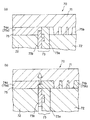
図1(a)〜(d)は、本発明の樹脂成形体の成形方法の一の実施の形態に使用する金型を模式的に示す断面図である。本実施の形態は、樹脂を金型のキャビティ内に射出するときに樹脂の流れ抵抗が大きい(流れ難い)一の領域と、他の一の領域(樹脂の流れ抵抗が小さい(流れ易い)領域)から構成されるキャビティを有する金型を使用して、樹脂成形体を一体成形する樹脂成形体の成形方法である。
【0012】
本実施の形態の樹脂成形体の成形方法は、図1(a)に示す、意匠側金型部1、非意匠側金型部2及び可動ブロック3を備えてなる金型10を使用して、射出成形により樹脂成形体を成形するものである。金型10のキャビティ5は、図1(b)に示す樹脂の流れ抵抗が小さい領域5aと、樹脂の流れ抵抗が大きい領域5bとの二つの領域に区分けされる。樹脂の充填方法は、まず、図1(b)に示すように、可動ブロック3を意匠側金型部1に突き合わせるように移動することによってキャビティ5を仕切り、可動ブロック3、意匠側金型部1及び非意匠側金型部2の間にキャビティ5aを形成する。そして、一次樹脂4aをキャビティ5a内に射出する。このとき、キャビティ5aは、樹脂の流れ抵抗が小さい領域であるため、大きな射出圧力をかけなくても容易に樹脂を射出し充填することができる。次に、図1(c)に示すように、可動ブロック3を引き下げて(退避させて)、一次樹脂4a、意匠側金型部1及び非意匠側金型部2の間(可動ブロック3によって塞がれていた領域)に樹脂の流れ抵抗が大きいキャビティ5bを形成する。そして、二次樹脂4bをキャビティ5b内に射出して、一次樹脂4aと、見切り部6で接合する。これにより、樹脂の流れ抵抗が小さい領域と樹脂の流れ抵抗が大きい領域に別々に樹脂を充填することができ、それぞれの領域に適した条件で樹脂を射出・充填することができるため、射出圧力を過剰に大きくする必要がなく、バリの発生等を防止することができる。また、一つの金型で成形する場合より、短時間で樹脂を充填することができ、充填効率を向上させることができる。
【0013】
一次樹脂4a、二次樹脂4bはともに、溶融状態で金型10のキャビティ5に射出、充填され、金型10内で冷却されて樹脂成形体の形状となる。金型10内で形成された樹脂成形体形状物は、金型10から取り出し、通常の方法で表面処理等を施して樹脂成形体として完成させる。
【0014】
本発明において、キャビティ5に樹脂が充填されるときの流れ抵抗の大きさは、一定量の樹脂をキャビティ5に充填したときの型締め力で表される。
【0015】
本実施の形態では、金型10のキャビティ5が、キャビティ5aとキャビティ5bの二つの領域から構成される(二つの領域に区分けされる)場合について説明したが、本発明の樹脂成形体の成形方法においては、金型のキャビティは三以上の領域に区分けされていてもよく、その場合には三以上の領域を一以上の可動ブロックを意匠側金型部に突き合わせるように移動することによって領域毎に仕切り、可動ブロックによって仕切られた領域に一次樹脂を射出し、その後、可動ブロックを順次退避させ、キャビティ内の可動ブロックで塞がれていた領域に順次二次以降の樹脂を射出し、各領域に射出する樹脂を見切り部で接合するようにしてもよい。
【0016】
本実施の形態の樹脂成形体の成形方法においては、図1(c)に示す、一次樹脂4aと二次樹脂4bとは、色及び/又は材質が異なるものであってもよい。たとえば、一次樹脂4aに添加する顔料と二次樹脂4bに添加する顔料とを異ならせて2色の樹脂成形体とすることができ、また、一次樹脂4aと二次樹脂4bとをそれぞれ機能の異なる樹脂とし、部分的に機能の異なる一体成形による樹脂成形体を得ることができる。一次樹脂4aと二次樹脂4bの樹脂の機能及び添加する顔料を同時に異ならせてもよい。また、金型のキャビティが三以上の領域から構成される場合には、少なくとも一つの領域に射出する樹脂の色及び/又は材質が異なるものであってもよい。たとえば、少なくとも一つの領域に射出する樹脂に添加する顔料と他の領域に射出する樹脂に添加する顔料とを異ならせて多色成形品とすることができ、また、少なくとも一つの領域に射出する樹脂を、他の領域に射出する樹脂とは異なる機能の樹脂とすることにより、部分的に機能の異なる一体成形による樹脂成形体を得ることができる。
【0017】
本実施の形態は、図3に示すような、スピーカー設置位置等に網状部が形成された自動車のドアトリムの製造に好適に適用することができる。図3に示す自動車のドアトリム31は、自動車のドアの内面に装着され、ドア内部に埋込設置されたスピーカーからの音が良好に伝達されるように、多数の網目を有する網状部32が形成されている。このような網状部32が形成されたドアトリム31を射出成形により一体成形する場合には、金型のキャビティの網状部32に相当する領域における樹脂の流れ難さ(流れ抵抗)が、その他の部分33に相当する領域における樹脂の流れ難さ(流れ抵抗)より大きく、網状部32に相当する領域に樹脂を充填し難い。そのため、ドアトリム31の網状部32に相当する金型のキャビティを図1(c)の5bとし、その他の部分33に相当する金型のキャビティを図1(c)の5aとして、上記本実施の形態の成形方法を適用することにより、網状部32も効率的に成形することができ、ドアトリム31を高圧で樹脂を充填することなく、効率的に一体成形することができる。このとき、ドアトリム31の網状部32を形成する樹脂(4b)をその他の部分33を形成する樹脂(4a)とは異なった吸音性に優れた材質のものとしてもよい。また、樹脂4aと樹脂4bのそれぞれに添加する顔料を違うものとし、2色の成形体としてもよい。
【0018】
本実施の形態の樹脂成形体の成形方法に使用する金型は、図1(b)に示すように、可動ブロック3と意匠側金型部1との間の突き合わせ隙間(t1)が、0.1mm以下であることが好ましい。この場合、可動ブロック3と意匠側金型部1との間の突き合わせ隙間(t1)は、0mmであってもよい。すなわち、可動ブロック3と意匠側金型部1とを完全に接触させた状態であってもよい。
【0019】
このように構成することによって、構成が簡易であるとともに、可動ブロック3と意匠側金型部1との間の突き合わせ隙間(t1)が0.1mm以下であるため、一次樹脂4aの、二次樹脂に対応するキャビティ5b内への進入が防止され、樹脂接合部の見切り部6が端麗で、意匠性に優れた樹脂成形体を得ることが可能となる。なお、非意匠側金型部2は、金型表面に意匠を施して、第2の意匠側金型部としてもよい。また、可動ブロック3は、通常、図1(a)〜(d)に示すように、非意匠側金型部2に設けることが多いが、意匠側金型部1に設けて、移動して非意匠側金型部2に突き合わされるように構成したものであってもよい。
【0020】
本発明に用いられる樹脂は、特に制限されるものではなく、その流動性の如何に拘わらず、あらゆる種類の熱可塑性樹脂を用いることができる。
【0021】
また、その他の成形条件については、通常の射出成形の場合と同様な条件を用いることができ、金型のキャビティの各領域に適した射出圧力で射出成形するとよい。
【0022】
図1(a)及び(b)に示すように、本実施の形態においては、可動ブロック3の移動を制止するストッパー7をさらに備えたものとすることが、可動ブロック3と意匠側金型部1との間の突き合わせ隙間(t1)を特定範囲内に確保するため、及び耐久性をさらに向上させるために好ましい。
【0023】
この場合、ストッパー7は、可動ブロック3と当接する当接ブロック7aとすることが好ましく、さらに、当接ブロック7aを構成する材料の硬度を、可動ブロック3を構成する材料の硬度よりも小とすることがさらに好ましい。このように構成することによって、可動ブロック3と当接ブロック7aとの当接、衝合による摩耗を当接ブロック7a側だけに限定して、摩耗した当接ブロック7aだけを取り替えることにより、容易に可動ブロック3と意匠側金型部1との間の突き合わせ隙間(t1)を特定の範囲に確保することができる。
【0024】
上記ストッパー7(当接ブロック7a)は、金型内の、たとえば、非意匠側金型部2上に設けてもよく、また、金型外の所定箇所に、ストロークエンドブロック等を設けたものであってもよい。また、図1(d)に示すように、可動ブロック3に設けて、非意匠側金型2と当接させてもよい。
【0025】
図2(a)〜(c)は、本発明の樹脂成形体の成形方法の他の実施の形態に使用する金型を模式的に示す断面図である。本実施の形態の樹脂成形体の成形方法は、図2(a)に示す、意匠側金型部11、非意匠側金型部12及び可動ブロック13を備えてなる金型20を使用して、射出成形により樹脂成形体を成形するものである。金型20のキャビティ15は、図2(b)に示す樹脂の流れ抵抗が小さい(流れ易い)領域15aと、図2(c)に示す樹脂の流れ抵抗が大きい(流れ難い)領域15bとの二つの領域から構成される(二つの領域に区分けされる)。樹脂の充填方法は、まず、図2(b)に示すように、可動ブロック13を意匠側金型部11に突き合わせるように移動することによってキャビティ15を仕切り、可動ブロック13、意匠側金型部11及び非意匠側金型部12の間にキャビティ15aを形成する。そして、一次樹脂14aをキャビティ15a内に射出する。このとき、キャビティ15aは、樹脂の流れ抵抗が小さい領域であるため、射出圧力を高圧にしなくても容易に樹脂を射出し充填することができる。次に、図2(c)に示すように、可動ブロック13を引き下げて(退避させて)、一次樹脂14a、意匠側金型部11及び非意匠側金型部12の間(可動ブロック13によって塞がれていた領域)にキャビティ15bを形成する。そして、二次樹脂14bをキャビティ15b内に射出して、一次樹脂14aと、見切り部(線)16で接合する。このとき、キャビティ15bは、樹脂の流れ抵抗が大きい領域であるが、この部分だけに樹脂を充填すればよいため、高圧をかけずに樹脂を充填することができ、且つ短時間で樹脂を充填することができ、充填効率を向上させることができる。
【0026】
一次樹脂14a、二次樹脂14bはともに、溶融状態で金型20のキャビティ15に射出、充填され、金型20内で冷却されて樹脂成形体の形状となる。金型20内で形成された樹脂成形体形状物は、金型20から取り出し、通常の方法で表面処理等を施して樹脂成形体として完成させる。
【0027】
本実施の形態では、図2(a)〜(c)に示すように、見切り部16に対応する意匠側金型部11の先端部の断面平面部分の幅(W)が、0.5mm以下であるとともに、可動ブロックの長さ(L)が、見切り部16よりも、複数の樹脂のうち一次樹脂14a側に、0.1mm以上延長されてなることが好ましい。
【0028】
このように意匠側金型部11の先端部の断面平面部分の幅(W)が、0.5mm以下と狭い場合には、この部分の耐久性が問題となり易いので、この部分には耐摩耗性の高い材料を用いるか、又は耐摩耗性の表面処理等を施すことが好ましい。
【0029】
上述のように、意匠側金型部11の先端部の断面平面部分の幅(W)が狭い場合には、可動ブロックの長さ(L)を、見切り部16よりも、一次樹脂14a側に、0.1mm以上延長することによって、構成が簡易であるとともに、一次樹脂14aの、二次樹脂に対応するキャビティ15b内への進入が防止され、樹脂接合部の見切り部16が端麗で、意匠性に優れた樹脂成形体を得ることが可能となる。
【0030】
この場合、可動ブロック13と意匠側金型部11との間の突き合わせ隙間(t2)が0mmより大であるため両者は当接することがなく、耐久性を向上させることが可能であるとともに、突き合わせ隙間(t1)が0.1mm以下であるため、一次樹脂14aの、二次樹脂に対応するキャビティ15b内への進入を防止し、樹脂接合部の見切り部16が端麗で、意匠性に優れた樹脂成形体を得る上で好ましい。
【0031】
この場合も、上述の場合と同様に、可動ブロックの移動を制限するストッパー(図示せず)をさらに備えたものとすること、ストッパーとして、非意匠側金型部に設けた、可動ブロックと当接する当接ブロックとすること、及び当接ブロックを構成する材料の硬度を、可動ブロックを構成する材料の硬度よりも小とすること等が好ましい。
【0032】
図4(a)、(b)は、本発明の樹脂成形体の成形方法の他の実施の形態に使用する金型を模式的に示す断面図である。本実施の形態の樹脂成形体の成形方法は、図4(a)に示す、意匠側金型部41、非意匠側金型部42及び可動ブロック43を備えてなる金型40を使用して、射出成形により樹脂成形体を成形するものである。金型40のキャビティ45は、図4(a)に示す樹脂の流れ抵抗が小さい(流れ易い)領域(キャビティ)45aと、樹脂の流れ抵抗が大きい(流れ難い)領域(キャビティ)45bとの二つの領域から構成される(二つの領域に区分けされる)。
【0033】
本実施の形態では、45aの可動ブロック43近傍に肉厚部46が形成されている。キャビティ45aに一次樹脂44aを充填し、可動ブロック43近傍において、一次樹脂44aが固化し始めた直後から、遅くとも一次樹脂44aの可動ブロック43近傍が完全に固化する前に、可動ブロック43をキャビティ45a内から退避させた後、キャビティ45bに二次樹脂44bを射出して一次樹脂44a中に潜り込ませるようにする。これにより、見切り線が良好で、意匠性に優れた一体成形品が得られると同時に、二次樹脂44bが一次樹脂44a中に潜り込んだ状態で接合される。
【0034】
図5(a)、(b)は、本発明の樹脂成形体の成形方法の他の実施の形態に使用する金型を模式的に示す断面図である。本実施の形態の樹脂成形体の成形方法は、図5(a)に示す、意匠側金型部51、非意匠側金型部52及び可動ブロック53を備えてなる金型50を使用して、射出成形により樹脂成形体を成形するものである。金型50のキャビティ55は、図5(a)に示す樹脂の流れ抵抗が小さい(流れ易い)領域(キャビティ)55aと、樹脂の流れ抵抗が大きい(流れ難い)領域(キャビティ)55bとの二つの領域から構成される(二つの領域に区分けされる)。
【0035】
本実施の形態では、可動ブロック53の先端が斜めに、つまり、可動ブロック53の一次樹脂54aと接する側端が、意匠面側から非意匠面側に向かうに従って、次第に肉薄になるように斜めに形成されている。そして、その斜めの面に凹凸56が形成されている。これにより、キャビティ55aに一次樹脂54aを射出した後、一次樹脂54aの可動ブロック53近傍が固化した後に、可動ブロック53の退避によって生じたキャビティ55bに二次樹脂54bを射出すると、二次樹脂54bが一次樹脂54aの非意匠面側に流れ込み、一次樹脂54aを非意匠面側から意匠面側へ向かって押圧する結果、キャビティ55との隙間が塞がれる。同時に一次樹脂54aと二次樹脂54bとの接合面には凹凸56が形成されているから、接合強度を向上させることができる。
【0036】
尚、本実施の形態において、可動ブロック53の先端を直線上に斜めにカットする他に、図6に示すように可動ブロック63の先端を階段状にカットしてもよい。図6において、60は金型、61は意匠側金型部、62は非意匠側金型部、64aは一次樹脂、64bは二次樹脂、65a及び65bはキャビティをそれぞれ示す。
【0037】
また、図7に示すように、可動ブロック73を二つの可動ブロック片73aと73bとによって構成し、各ブロック片が、二次樹脂が射出される前にキャビティ75内から退避した際に、非意匠面と平坦な面になるようにすることにより、非意匠面が平坦な成形品を得ることができる。図7において、70は金型、71は意匠側金型部、72は非意匠側金型部、74aは一次樹脂、74bは二次樹脂、75a及び75bはキャビティをそれぞれ示す。
【0038】
図8(a)、(b)は、本発明の樹脂成形体の成形方法の他の実施の形態に使用する金型を模式的に示す断面図である。本実施の形態の樹脂成形体の成形方法は、図8(a)に示す、意匠側金型部81、非意匠側金型部82及び可動ブロック83を備えてなる金型80を使用して、射出成形により樹脂成形体を成形するものである。金型80のキャビティ85は、図8(a)に示す樹脂の流れ抵抗が小さい(流れ易い)領域(キャビティ)85aと、樹脂の流れ抵抗が大きい(流れ難い)領域(キャビティ)85bとの二つの領域から構成される。
【0039】
本実施の形態では、可動ブロック83が一次樹脂84aを射出する領域(キャビティ85a)の可動ブロック83近傍を、厚さ方向に垂直、且つ見切り線に垂直な方向に対してアンダーカットになるように(アンダーカット部86を形成するように)区画する形状に形成されている。本実施の形態においては、可動ブロック83の退避後に二次樹脂84bを射出すると、可動ブロック83は非意匠面に、一次樹脂84aのアンダーカット部86が配置されるような構造をしているため、二次樹脂84bが一次樹脂84aの非意匠面側に入り、一次樹脂84a近傍部を意匠側金型部81に押し付ける力が働き、一次樹脂84aと意匠側金型部81との隙間に二次樹脂84bが浸入し難くなるため、見切り線も向上する。
【0040】
【実施例】
以下、本発明を実施例により具体的に説明するが、本発明はこれら実施例に限定されるものではない。
【0041】
図3に示す自動車のドアトリムを以下のようにして作製した。このドアトリムは、射出成形時に、網状部の樹脂の流れ抵抗が、網状部以外の部分の樹脂の流れ抵抗より、大きいものである。
【0042】
(実施例1)
図3に示す自動車のドアトリムを、図1に示す金型を使用して作製したときの、網状部以外の部分に樹脂が一定量充填されたときの内圧を測定し、型締め力を算出した。結果を表1に示す。
【0043】
成形条件は、以下の通りである。
【0044】
網状部以外の部分について、射出温度を220℃、射出圧力を90MPa、使用樹脂をポリプロピレン、樹脂の充填量を1000cm3とした。また、網状部以外の部分に相当するキャビティの、金型が型締めされる方向に投影した投影図の面積は2905cm2であった。
【0045】
(比較例1)
図3に示す自動車のドアトリムを、通常の一体成形用金型を使用して、網状部及び網状部以外の部分に相当するキャビティを同時に充填する(一度の射出で両方のキャビティを充填する)方法で作製し、樹脂が一定量充填されたときの内圧を測定し、型締め力を算出した。結果を表1に示す。
【0046】
成形条件は以下の通りである。
【0047】
射出温度、射出圧力、使用樹脂及び樹脂の充填量は、実施例1と同様にした。キャビティ全体の、金型が型締めされる方向に投影した、投影図の面積は3087cm2であった。
【0048】
【表1】

表1より、実施例1の型締め力のほうが、比較例1の型締め力より小さく、実施例1のほうが低い圧力で樹脂を充填することができるため、小さい型締め力で金型を型締めすることができることがわかる。
【0050】
【発明の効果】
以上説明したように、本発明によって、樹脂成形体を射出成形するときに、金型のキャビティ内に、樹脂の流れ抵抗が大きく、樹脂が流れ難い領域がある場合に、その樹脂成形体を高圧を要さず、効率的に一体成形することができる樹脂成形体の成形方法を提供することができる。
【図面の簡単な説明】
【図1】 本発明の樹脂成形体の成形方法の一の実施の形態に使用する金型を模式的に示す断面図で、(a)は可動ブロックを意匠側金型部に突き合わせるように移動する前の状態、(b)は可動ブロックを意匠側金型部に突き合わせるように移動した後の状態、(c)は複数の樹脂を射出した状態、(d)はストッパー(当接ブロック)を可動ブロックに設定した例をそれぞれ示す。
【図2】 本発明の樹脂成形体の成形方法の他の実施の形態に使用する金型を模式的に示す断面図で、(a)は可動ブロックを意匠側金型部に突き合わせるように移動する前の状態、(b)は可動ブロックを意匠側金型部に突き合わせるように移動した後の状態、(c)は複数の樹脂を射出した状態をそれぞれ示す。
【図3】 自動車のドアトリムを模式的に示す平面図である。
【図4】 本発明の樹脂成形体の成形方法の他の実施の形態に使用する金型を模式的に示す断面図で、(a)は可動ブロックを意匠側金型部に突き合わせるように移動した後の状態、(b)は複数の樹脂を射出した状態をそれぞれ示す。
【図5】 本発明の樹脂成形体の成形方法の他の実施の形態に使用する金型を模式的に示す断面図で、(a)は可動ブロックを意匠側金型部に突き合わせるように移動した後の状態、(b)は複数の樹脂を射出した状態をそれぞれ示す。
【図6】 本発明の樹脂成形体の成形方法の他の実施の形態に使用する金型を模式的に示す断面図で、(a)は可動ブロックを意匠側金型部に突き合わせるように移動した後の状態、(b)は複数の樹脂を射出した状態をそれぞれ示す。
【図7】 本発明の樹脂成形体の成形方法の他の実施の形態に使用する金型を模式的に示す断面図で、(a)は可動ブロックを意匠側金型部に突き合わせるように移動した後の状態、(b)は複数の樹脂を射出した状態をそれぞれ示す。
【図8】 本発明の樹脂成形体の成形方法の他の実施の形態に使用する金型を模式的に示す断面図で、(a)は可動ブロックを意匠側金型部に突き合わせるように移動した後の状態、(b)は複数の樹脂を射出した状態をそれぞれ示す。
【符号の説明】
1…意匠側金型部、2…非意匠側金型部、3…可動ブロック、4…複数の樹脂、4a…先の射出順位の樹脂(一次樹脂)、4b…後の射出順位の樹脂(二次樹脂)、5…キャビティ、5a…一次樹脂に対応するキャビティ、5b…二次樹脂に対応するキャビティ、6…見切り部、7…ストッパー、7a…当接ブロック、10…金型、11…意匠側金型部、12…非意匠側金型部、13…可動ブロック、14…複数の樹脂、14a…一次樹脂、14b…二次樹脂、15…キャビティ、15a…一次樹脂に対応するキャビティ、15b…二次樹脂に対応するキャビティ、16…見切り部、20…金型、31…ドアトリム、32…網状部、33…ドアトリムの網状部以外の部分、40…金型、41…意匠側金型部、42…非意匠側金型部、43…可動ブロック、44a…先の射出順位の樹脂(一次樹脂)、44b…後の射出順位の樹脂(二次樹脂)、45a,45b…キャビティ、46…肉厚部、50…金型、51…意匠側金型部、52…非意匠側金型部、53…可動ブロック、54a…一次樹脂、54b…二次樹脂、55,55a,55b…キャビティ、56…凹凸、60…金型、61…意匠側金型部、62…非意匠側金型部、63…可動ブロック、64a…一次樹脂、64b…二次樹脂、65,65a,65b…キャビティ、70…金型、71…意匠側金型部、72…非意匠側金型部、73…可動ブロック、73a,73b…可動ブロック片、74a…一次樹脂、74b…二次樹脂、75,75a,75b…キャビティ、80…金型、81…意匠側金型部、82…非意匠側金型部、83…可動ブロック、83a,83b…可動ブロック片、84a…一次樹脂、84b…二次樹脂、85,85a,85b…キャビティ、86…アンダーカット部、t1,t2…可動ブロックと意匠側金型部との間の突き合わせ隙間、L…可動ブロックの長さ、W…意匠側金型部の先端部の断面平面部分の幅。[0001]
BACKGROUND OF THE INVENTION
The present invention relates to a method for molding a resin molded body. More specifically, when a resin molded body is injection-molded, if there is a region in the mold cavity where the flow resistance of the resin is large and difficult to flow, the resin molding is performed. The present invention relates to a method for molding a resin molded body capable of efficiently integrally molding a body.
[0002]
[Prior art]
In the injection molding method of a resin molded body, a plastic material (resin) is heated and melted and injected into a mold cavity by a screw or a plunger, and then cooled, solidified or heated and cured in the mold to obtain a resin molded body. Is. By this injection molding method, it is possible to obtain a highly accurate resin molding that is faithful to the shape of the cavity of the mold.
[0003]
However, such an injection molding method also has a structure in which a resin molded body to be obtained has a partially fine structure, and a mold cavity corresponding to the part has a thin and / or complicated structure. The injected resin is difficult to be filled in the portion, and there are problems that it takes time for filling, a high filling pressure is required, and a portion that is not filled remains.
[0004]
As described above, when a resin is injected into the mold cavity and there is a portion that is difficult to be filled because the resin is difficult to flow, a resin molded body corresponding to the portion that is difficult to be filled with the resin is replaced with another mold. The target resin molded body is formed by combining the two resin molded bodies obtained by molding the resin molded body from the original resin molded body and excluding the portion where it is difficult to fill the resin with another mold. Can be obtained. However, in this way, two resin molded bodies or, in the case of a more complicated structure, three or more resin molded bodies are separately injection-molded using different molds, and the resulting resin molded body is When combining a single resin molded body, two or more molds must be prepared, each must be separately injection molded, and the final injection molded body must be combined into one, There was a problem that they did not fit together.
[0005]
Therefore, if such a resin molded body having a partially fine structure is to be integrally molded by injection molding with a single mold, it is necessary to forcibly fill the resin in a portion where it is difficult to fill the resin. For this reason, there is a problem that a high pressure is required, an extra operation such as reducing the viscosity of the resin by heating the portion, a complicated apparatus is required, and productivity is lowered.
[0006]
For example, as shown in FIG. 3, there is a case in which a net-like portion is formed at a speaker installation position so that sound from a speaker can be satisfactorily transmitted, but the door trim is integrally formed by injection molding. In this case, the region corresponding to the mesh portion of the mold cavity is less likely to flow the resin than the region corresponding to the other portion, and the region corresponding to the mesh portion is less likely to be filled with resin. It is necessary to heat only the region corresponding to the above to improve the flow of the resin, and there is a problem that the efficiency is very low.
[0007]
[Problems to be solved by the invention]
The present invention has been made in view of the above-described problems. When a resin molded body is injection-molded, if there is a region where the resin flow resistance is difficult to flow in the mold cavity, the resin molded body is It aims at providing the molding method of the resin molding which can be integrally molded efficiently.
[0008]
[Means for Solving the Problems]
In order to achieve the above object, the present invention provides the following method for molding a resin molded body.
[1] Resin is injected into the mold cavity With mesh A method of molding a resin molded body in which a resin molded body is integrally molded, wherein the resin filled in the cavity corresponds to difficulty in flowing due to the structure of the cavity. , Corresponds to the area corresponding to the net-like portion where resin does not flow easily and the other part where resin flows easily Dividing into regions, and partitioning one of the plurality of divided regions by moving one or more movable blocks to the design side mold part and bringing them into contact therewith, and by the movable blocks The primary resin is injected into the partitioned area, then the movable block is sequentially withdrawn from the cavity, and the secondary and subsequent resins are sequentially injected into other areas blocked by the movable block inside the cavity. A method for molding a resin molded body characterized by the above.
[2] Said It corresponds to the area corresponding to the net-like part and the other parts. The method for molding a resin molded body according to [1], wherein each of the resins injected into the region is joined at a parting portion.
[3] Said It corresponds to the area corresponding to the net-like part and the other parts. Of the resin injected into the region, the color and / or material of the resin injected into at least the one region is different from the color and / or material of the resin injected into the other region [1] or [2 ] The molding method of the resin molding of description.
[4] The method for molding a resin molded body according to any one of [1] to [3], wherein a butt gap (t1) between the movable block and the design side mold part is 0.1 mm or less.
[5] The method for molding a resin molded body according to any one of [1] to [4], wherein the mold includes a stopper that stops movement of the movable block.
[6] The method for molding a resin molded body according to [5], wherein the stopper is a contact block that is provided in the non-design side mold part and contacts the movable block.
[7] The method of molding a resin molded body according to [6], wherein the hardness of the material constituting the contact block is smaller than the hardness of the material constituting the movable block.
[8] The width (W) of the cross-sectional plane portion of the distal end portion of the design side mold portion corresponding to the parting part is 0.5 mm or less, and the length (L) of the movable block is the parting part. The method of molding a resin molded body according to any one of [2] to [7], wherein the resin is further extended by 0.1 mm or more to the resin side of the previous injection order among the plurality of resins.
[9] The method for molding a resin molded body according to [8], wherein a butt gap (t2) between the movable block and the design side mold part is greater than 0 mm and 0.1 mm or less.
[10] The method for molding a resin molded body according to [8] or [9], wherein the mold includes a stopper that restricts movement of the movable block.
[11] The method for molding a resin molded body according to [10], wherein the stopper is a contact block that is provided in the non-design side mold part and contacts the movable block.
[12] The method for molding a resin molded body according to [11], wherein the hardness of the material constituting the contact block is smaller than the hardness of the material constituting the movable block.
[13] Immediately after the primary resin starts to solidify in the vicinity of the movable block, and after the movable block of the primary resin is completely solidified at the latest, the movable block is retracted from the cavity, and then the interior of the cavity The method for molding a resin molded body according to any one of [1] to [12], wherein the secondary resin is injected into the remaining space and is submerged in the primary resin.
[14] The method for molding a resin molded body according to [13], wherein the vicinity of the movable block of the primary resin into which the secondary resin enters is a thick portion.
[15] The side end in contact with the primary resin of the movable block is formed obliquely so as to gradually become thinner from the design surface side toward the non-design surface side, and unevenness is formed on the oblique surface. ] The molding method of the resin molding in any one of [14].
[16] The movable block includes at least two blocks, and each block piece becomes a non-design surface and a flat surface when retracted from the cavity before the secondary resin is injected [15]. ] The molding method of the resin molding of description.
[17] The movable block is formed in a shape that partitions the vicinity of the movable block in the one region for injecting the primary resin so as to be undercut perpendicular to the thickness direction and perpendicular to the parting line. The method for molding a resin molded body according to any one of [1] to [16].
[0009]
In this way, when the resin molded body is integrally formed by injection molding, the inside of the mold cavity is divided into a plurality of regions, the regions are partitioned by a movable block, and the resin is moved while the movable block is moved (withdrawn). Since injection filling is used, the resin can be injected and filled under injection conditions suitable for each area in the cavity, so even when resin is injected into areas with poor fluidity (areas with high resin flow resistance) It can be filled efficiently without requiring high pressure.
[0010]
DETAILED DESCRIPTION OF THE INVENTION
Hereinafter, embodiments of the present invention will be specifically described with reference to the drawings. However, the present invention is not limited to the following embodiments, and those skilled in the art will be able to do so without departing from the spirit of the present invention. It should be understood that design changes, improvements, and the like can be made as appropriate based on ordinary knowledge.
[0011]
FIGS. 1A to 1D are cross-sectional views schematically showing a mold used in one embodiment of a method for molding a resin molded body of the present invention. In the present embodiment, when the resin is injected into the cavity of the mold, one region where the resin flow resistance is large (difficult to flow) and the other region (the region where the resin flow resistance is small (easy to flow)) Is a molding method of a resin molded body in which a resin molded body is integrally molded using a mold having a cavity composed of
[0012]
The molding method of the resin molded body of the present embodiment uses a
[0013]
Both the primary resin 4a and the
[0014]
In the present invention, the magnitude of the flow resistance when the resin is filled in the
[0015]
In the present embodiment, the case where the
[0016]
In the molding method of the resin molded body of the present embodiment, the primary resin 4a and the
[0017]
This embodiment can be suitably applied to the manufacture of an automobile door trim in which a mesh portion is formed at a speaker installation position or the like as shown in FIG. The automobile door trim 31 shown in FIG. 3 is mounted on the inner surface of the automobile door, and a
[0018]
As shown in FIG. 1B, the mold used for the molding method of the resin molded body of the present embodiment has a butt gap (t1) between the
[0019]
By configuring in this way, the configuration is simple and the butt gap (t1) between the
[0020]
The resin used in the present invention is not particularly limited, and any kind of thermoplastic resin can be used regardless of its fluidity.
[0021]
As other molding conditions, the same conditions as in the case of normal injection molding can be used, and it is preferable to perform injection molding at an injection pressure suitable for each region of the mold cavity.
[0022]
As shown in FIGS. 1A and 1B, in the present embodiment, the
[0023]
In this case, the
[0024]
The stopper 7 (
[0025]
2A to 2C are cross-sectional views schematically showing a mold used in another embodiment of the method for molding a resin molded body of the present invention. The molding method of the resin molded body of the present embodiment uses a
[0026]
Both the
[0027]
In the present embodiment, as shown in FIGS. 2A to 2C, the width (W) of the cross-sectional plane portion of the distal end portion of the design
[0028]
In this way, when the width (W) of the cross-sectional plane portion of the tip portion of the design
[0029]
As described above, when the width (W) of the cross-sectional plane portion of the tip portion of the design-
[0030]
In this case, since the butting gap (t2) between the
[0031]
In this case as well, as in the case described above, a stopper (not shown) for restricting the movement of the movable block is further provided, and the movable block provided on the non-design side mold part is used as a stopper. It is preferable that the contact block is in contact, and the hardness of the material constituting the contact block is smaller than the hardness of the material constituting the movable block.
[0032]
4 (a) and 4 (b) are cross-sectional views schematically showing a mold used in another embodiment of the method for molding a resin molded body of the present invention. The molding method of the resin molded body of the present embodiment uses a
[0033]
In the present embodiment, a
[0034]
FIGS. 5A and 5B are cross-sectional views schematically showing a mold used in another embodiment of the method for molding a resin molded body of the present invention. The molding method of the resin molded body of the present embodiment uses a
[0035]
In the present embodiment, the tip of the
[0036]
In the present embodiment, in addition to cutting the tip of the
[0037]
In addition, as shown in FIG. 7, the
[0038]
8A and 8B are cross-sectional views schematically showing a mold used in another embodiment of the method for molding a resin molded body of the present invention. The molding method of the resin molded body of the present embodiment uses a
[0039]
In the present embodiment, the vicinity of the
[0040]
【Example】
EXAMPLES The present invention will be specifically described below with reference to examples, but the present invention is not limited to these examples.
[0041]
The door trim of the automobile shown in FIG. 3 was produced as follows. In this door trim, the resin flow resistance in the mesh portion is greater than the resin flow resistance in the portion other than the mesh portion at the time of injection molding.
[0042]
Example 1
When the door trim of the automobile shown in FIG. 3 was produced using the mold shown in FIG. 1, the internal pressure when a certain amount of resin was filled in a portion other than the mesh portion was measured, and the clamping force was calculated. . The results are shown in Table 1.
[0043]
The molding conditions are as follows.
[0044]
For the portions other than the mesh portion, the injection temperature is 220 ° C., the injection pressure is 90 MPa, the resin used is polypropylene, and the resin filling amount is 1000 cm. Three It was. Further, the area of the projection corresponding to the portion other than the mesh portion projected in the direction in which the mold is clamped is 2905 cm. 2 Met.
[0045]
(Comparative Example 1)
3 is a method for simultaneously filling cavities corresponding to a mesh portion and a portion other than the mesh portion (filling both cavities in a single injection) using a normal integral mold. The mold clamping force was calculated by measuring the internal pressure when a certain amount of resin was filled. The results are shown in Table 1.
[0046]
The molding conditions are as follows.
[0047]
The injection temperature, injection pressure, resin used, and resin filling amount were the same as in Example 1. The projected area of the entire cavity, projected in the direction in which the mold is clamped, is 3087 cm. 2 Met.
[0048]
[Table 1]
From Table 1, the mold clamping force of Example 1 is smaller than the mold clamping force of Comparative Example 1, and Example 1 can fill the resin with a lower pressure. Therefore, the mold is molded with a small mold clamping force. You can see that it can be tightened.
[0050]
【The invention's effect】
As described above, according to the present invention, when a resin molded body is injection-molded, if there is a region where the resin flow resistance is large and the resin is difficult to flow in the mold cavity, the resin molded body is Therefore, it is possible to provide a method for molding a resin molded body that can be integrally molded efficiently.
[Brief description of the drawings]
FIG. 1 is a cross-sectional view schematically showing a mold used in an embodiment of a molding method for a resin molded body of the present invention, in which (a) abuts a movable block against a design side mold part. The state before moving, (b) is the state after moving the movable block so as to abut the design side mold part, (c) is the state where a plurality of resins are injected, (d) is the stopper (contact block) ) Is set as a movable block.
FIG. 2 is a cross-sectional view schematically showing a mold used in another embodiment of the method for molding a resin molded body of the present invention, in which (a) abuts the movable block against the design side mold part. The state before moving, (b) shows the state after moving the movable block so as to abut the design side mold part, and (c) shows the state where a plurality of resins are injected.
FIG. 3 is a plan view schematically showing a door trim of an automobile.
FIG. 4 is a cross-sectional view schematically showing a mold used in another embodiment of the method for molding a resin molded body of the present invention, in which (a) abuts the movable block against the design side mold part. The state after moving, (b) shows a state where a plurality of resins are injected.
FIG. 5 is a cross-sectional view schematically showing a mold used in another embodiment of the method for molding a resin molded body of the present invention, in which (a) abuts the movable block against the design side mold part; The state after moving, (b) shows a state where a plurality of resins are injected.
FIG. 6 is a cross-sectional view schematically showing a mold used in another embodiment of the method for molding a resin molded body of the present invention, in which (a) abuts the movable block against the design side mold part. The state after moving, (b) shows a state where a plurality of resins are injected.
FIG. 7 is a cross-sectional view schematically showing a mold used in another embodiment of the method for molding a resin molded body of the present invention, in which (a) abuts the movable block against the design side mold part. The state after moving, (b) shows a state where a plurality of resins are injected.
FIG. 8 is a cross-sectional view schematically showing a mold used in another embodiment of the molding method of the resin molded body of the present invention, in which (a) abuts the movable block against the design side mold part. The state after moving, (b) shows a state where a plurality of resins are injected.
[Explanation of symbols]
DESCRIPTION OF SYMBOLS 1 ... Design side metal mold | die part, 2 ... Non-design side metal mold | die part, 3 ... Movable block, 4 ... Several resin, 4a ... Previous injection | emission order resin (primary resin), 4b ... Later injection | emission order resin ( Secondary resin), 5 ... cavity, 5a ... cavity corresponding to the primary resin, 5b ... cavity corresponding to the secondary resin, 6 ... parting part, 7 ... stopper, 7a ... contact block, 10 ... mold, 11 ... Design side mold part, 12 ... Non-design side mold part, 13 ... Movable block, 14 ... Multiple resins, 14a ... Primary resin, 14b ... Secondary resin, 15 ... Cavity, 15a ... Cavity corresponding to primary resin, 15b ... cavity corresponding to secondary resin, 16 ... parting part, 20 ... mold, 31 ... door trim, 32 ... mesh part, 33 ... part other than mesh part of door trim, 40 ... mold, 41 ... design side mold Part, 42 ... non-design side mold part, 43 ... acceptable Block, 44a... Resin of the previous injection order (primary resin), 44b... Resin of the subsequent injection order (secondary resin), 45a, 45b... Cavity, 46.
Claims (17)
前記金型のキャビティ内を、前記キャビティ内に充填される前記樹脂の前記キャビティの構造による流れ難さに対応して、樹脂の流れ難い前記網状部に相当する領域と樹脂の流れ易いその他の部分に相当する領域に区分けして、
区分けされた前記複数の領域のうちの一の領域を、一以上の可動ブロックを意匠側金型部に移動させてそこに当接させることによって仕切るとともに、前記可動ブロックによって仕切られた領域に一次樹脂を射出し、
次いで、前記可動ブロックをキャビティ内から順次退避させ、前記キャビティ内部の前記可動ブロックによって塞がれていた他の領域に順次二次以降の樹脂を射出することを特徴とする樹脂成形体の成形方法。A method of molding a resin molded body, in which a resin molded body having a net-like portion is integrally molded by injecting resin into a cavity of a mold,
In the cavity of the mold, corresponding to the difficulty of flow of the resin filled in the cavity due to the structure of the cavity, a region corresponding to the mesh portion where resin does not flow easily and other portions where resin flows easily Divided into areas corresponding to
One of the plurality of divided regions is partitioned by moving one or more movable blocks to the design side mold part and bringing them into contact therewith, and is primary to the region partitioned by the movable blocks Injecting resin,
Next, the movable block is sequentially withdrawn from the cavity, and the secondary and subsequent resins are sequentially injected into other regions blocked by the movable block inside the cavity. .
Priority Applications (1)
| Application Number | Priority Date | Filing Date | Title |
|---|---|---|---|
| JP2002180259A JP4036689B2 (en) | 2002-06-20 | 2002-06-20 | Molding method of resin molding |
Applications Claiming Priority (1)
| Application Number | Priority Date | Filing Date | Title |
|---|---|---|---|
| JP2002180259A JP4036689B2 (en) | 2002-06-20 | 2002-06-20 | Molding method of resin molding |
Publications (2)
| Publication Number | Publication Date |
|---|---|
| JP2004017629A JP2004017629A (en) | 2004-01-22 |
| JP4036689B2 true JP4036689B2 (en) | 2008-01-23 |
Family
ID=31177441
Family Applications (1)
| Application Number | Title | Priority Date | Filing Date |
|---|---|---|---|
| JP2002180259A Expired - Fee Related JP4036689B2 (en) | 2002-06-20 | 2002-06-20 | Molding method of resin molding |
Country Status (1)
| Country | Link |
|---|---|
| JP (1) | JP4036689B2 (en) |
Families Citing this family (8)
| Publication number | Priority date | Publication date | Assignee | Title |
|---|---|---|---|---|
| JP4507861B2 (en) * | 2004-12-01 | 2010-07-21 | 河西工業株式会社 | Multicolor molded product molding method and mold |
| JP2007030291A (en) * | 2005-07-26 | 2007-02-08 | Kasai Kogyo Co Ltd | Multi-color molding, method and mold for molding the molding |
| JP2007130914A (en) * | 2005-11-11 | 2007-05-31 | Kasai Kogyo Co Ltd | Multicolor molded article and its molding method |
| JP2007144871A (en) * | 2005-11-29 | 2007-06-14 | Kasai Kogyo Co Ltd | Multicolor molded product and its molding method |
| JP4817429B2 (en) * | 2006-03-28 | 2011-11-16 | 河西工業株式会社 | Molding method for multicolor molded products |
| EP1952963B1 (en) * | 2007-02-02 | 2011-04-06 | Novem Car Interior Design GmbH | Injection moulding of a facing part for motor vehicles |
| JP6138863B2 (en) * | 2015-06-29 | 2017-05-31 | 本田技研工業株式会社 | Injection molding method and injection molding apparatus |
| US11446851B2 (en) * | 2019-04-29 | 2022-09-20 | Taiwan Semiconductor Manufacturing Company, Ltd. | Molding apparatus, manufacturing method of molded semiconductor device and molded semiconductor device |
-
2002
- 2002-06-20 JP JP2002180259A patent/JP4036689B2/en not_active Expired - Fee Related
Also Published As
| Publication number | Publication date |
|---|---|
| JP2004017629A (en) | 2004-01-22 |
Similar Documents
| Publication | Publication Date | Title |
|---|---|---|
| JP4036689B2 (en) | Molding method of resin molding | |
| KR0180045B1 (en) | Process for producing molded article made of synthetic resin | |
| EP0825007A1 (en) | Mold assembly for making multilayer molded article and method of making multilayer molded article using the same | |
| US5804117A (en) | Molding method for resin articles | |
| JP2009241463A (en) | Injection molding die and injection molding method | |
| JP2010274490A (en) | Mold | |
| KR0178866B1 (en) | Process for producing a bumper for a vehicle | |
| JP3289665B2 (en) | Injection mold | |
| JP2000127862A (en) | Manufacture of automobile trim and molding die therefor | |
| JP4394795B2 (en) | Injection molding method | |
| JP2701681B2 (en) | Method for producing resin molded product and molding die apparatus | |
| JPS5818216A (en) | Manufacture of molding | |
| JP3920808B2 (en) | Mold for composite molding | |
| JP2021011029A (en) | Manufacturing method of molded structure and molded structure | |
| JP3462164B2 (en) | Method of manufacturing weatherstrip | |
| JP4176357B2 (en) | Manufacturing method of injection molded products | |
| JP2005193634A (en) | Injection-molded product manufacturing method and mold assembly therefor | |
| JP2004291324A (en) | Mold for multicolor molding and multicolor molding method | |
| JP3226408B2 (en) | Automobile molding and manufacturing method thereof | |
| JP4057905B2 (en) | Glossy plastic composite injection molding method and injection molding apparatus for carrying out this method | |
| JP2019166652A (en) | Manufacturing method of formed structure | |
| JP2001138373A (en) | Injection molding method and injection mold | |
| JP2002187166A (en) | Mold for multicolor molding | |
| JP2679025B2 (en) | Method for manufacturing resin molded products | |
| JPH04339617A (en) | Sandwich molding method |
Legal Events
| Date | Code | Title | Description |
|---|---|---|---|
| A711 | Notification of change in applicant |
Free format text: JAPANESE INTERMEDIATE CODE: A712 Effective date: 20041112 |
|
| A621 | Written request for application examination |
Free format text: JAPANESE INTERMEDIATE CODE: A621 Effective date: 20050301 |
|
| A711 | Notification of change in applicant |
Free format text: JAPANESE INTERMEDIATE CODE: A712 Effective date: 20060418 |
|
| A977 | Report on retrieval |
Free format text: JAPANESE INTERMEDIATE CODE: A971007 Effective date: 20061005 |
|
| A131 | Notification of reasons for refusal |
Free format text: JAPANESE INTERMEDIATE CODE: A131 Effective date: 20061017 |
|
| A521 | Written amendment |
Free format text: JAPANESE INTERMEDIATE CODE: A523 Effective date: 20061214 |
|
| A02 | Decision of refusal |
Free format text: JAPANESE INTERMEDIATE CODE: A02 Effective date: 20070703 |
|
| A521 | Written amendment |
Free format text: JAPANESE INTERMEDIATE CODE: A523 Effective date: 20070830 |
|
| A911 | Transfer of reconsideration by examiner before appeal (zenchi) |
Free format text: JAPANESE INTERMEDIATE CODE: A911 Effective date: 20070910 |
|
| TRDD | Decision of grant or rejection written | ||
| A01 | Written decision to grant a patent or to grant a registration (utility model) |
Free format text: JAPANESE INTERMEDIATE CODE: A01 Effective date: 20071023 |
|
| A61 | First payment of annual fees (during grant procedure) |
Free format text: JAPANESE INTERMEDIATE CODE: A61 Effective date: 20071030 |
|
| R150 | Certificate of patent or registration of utility model |
Free format text: JAPANESE INTERMEDIATE CODE: R150 |
|
| FPAY | Renewal fee payment (event date is renewal date of database) |
Free format text: PAYMENT UNTIL: 20101109 Year of fee payment: 3 |
|
| FPAY | Renewal fee payment (event date is renewal date of database) |
Free format text: PAYMENT UNTIL: 20101109 Year of fee payment: 3 |
|
| FPAY | Renewal fee payment (event date is renewal date of database) |
Free format text: PAYMENT UNTIL: 20111109 Year of fee payment: 4 |
|
| FPAY | Renewal fee payment (event date is renewal date of database) |
Free format text: PAYMENT UNTIL: 20111109 Year of fee payment: 4 |
|
| FPAY | Renewal fee payment (event date is renewal date of database) |
Free format text: PAYMENT UNTIL: 20121109 Year of fee payment: 5 |
|
| LAPS | Cancellation because of no payment of annual fees |