JP3852677B2 - Body support device such as chair and manufacturing method thereof - Google Patents
Body support device such as chair and manufacturing method thereof Download PDFInfo
- Publication number
- JP3852677B2 JP3852677B2 JP2001190106A JP2001190106A JP3852677B2 JP 3852677 B2 JP3852677 B2 JP 3852677B2 JP 2001190106 A JP2001190106 A JP 2001190106A JP 2001190106 A JP2001190106 A JP 2001190106A JP 3852677 B2 JP3852677 B2 JP 3852677B2
- Authority
- JP
- Japan
- Prior art keywords
- frame
- sheet
- net
- chair
- edge
- Prior art date
- Legal status (The legal status is an assumption and is not a legal conclusion. Google has not performed a legal analysis and makes no representation as to the accuracy of the status listed.)
- Expired - Fee Related
Links
Images


Classifications
-
- A—HUMAN NECESSITIES
- A47—FURNITURE; DOMESTIC ARTICLES OR APPLIANCES; COFFEE MILLS; SPICE MILLS; SUCTION CLEANERS IN GENERAL
- A47C—CHAIRS; SOFAS; BEDS
- A47C7/00—Parts, details, or accessories of chairs or stools
- A47C7/02—Seat parts
- A47C7/28—Seat parts with tensioned springs, e.g. of flat type
- A47C7/282—Seat parts with tensioned springs, e.g. of flat type with mesh-like supports, e.g. elastomeric membranes
-
- A—HUMAN NECESSITIES
- A47—FURNITURE; DOMESTIC ARTICLES OR APPLIANCES; COFFEE MILLS; SPICE MILLS; SUCTION CLEANERS IN GENERAL
- A47C—CHAIRS; SOFAS; BEDS
- A47C31/00—Details or accessories for chairs, beds, or the like, not provided for in other groups of this subclass, e.g. upholstery fasteners, mattress protectors, stretching devices for mattress nets
- A47C31/02—Upholstery attaching means
- A47C31/023—Upholstery attaching means connecting upholstery to frames, e.g. by hooks, clips, snap fasteners, clamping means or the like
Landscapes
- Chair Legs, Seat Parts, And Backrests (AREA)
- Mattresses And Other Support Structures For Chairs And Beds (AREA)
Description
【0001】
【発明の属する技術分野】
本発明は、椅子のような身体支持装置及びその製造方法に関するものである。
【0002】
【従来の技術】
椅子の一形態として、座体や背もたれを、略四角形枠等のフレームにネット状のシートを張った構造にしたものがあり、このタイプの椅子は一般にネット椅子(或いはネットチェア)と呼ばれている。
【0003】
そして、椅子の座体を構成するフレームにネットを固定する手段の従来例を図8に示している。このうち図8(a)に示し、特表8−507935号公報に開示された例は、フレーム100を合成樹脂で製造するにおいて、インサート成形法によってネット101の縁部101aをフレーム100に埋設している。
【0004】
また、図8(b)に示す例では、フレーム100とネット101とを共に同種類の合成樹脂製として、高周波溶着法や超音波溶着法によって、ネット101の縁部101aをフレーム100の表面に溶着している。
【0005】
更に、図8(c)に示す例では、フレーム100の外周に半径外向きに開放された環状溝102を形成する一方、ネット101の縁部101aを筒状に縫着してこれに線材103を嵌入し、該線材103を環状溝102に強制的に嵌入させている。
【0006】
【発明が解決しようとする課題】
図8(a)のようにインサート成形によって埋設したものは、フレーム100の内周部100aとネット101との境界部位がエッジ状になっているため、フレーム100の内径側の空間に張設したネット101の面に略直交する方向に体重等の荷重が掛かると、前記境界部位のエッジにてネットの繊維に剪断力が作用し、当該ネット101の耐久性が低いという問題があった。
【0007】
同様に、図8(b)のようにフレーム100の表面にネット101を溶着したものは、ネット101に作用した引っ張り力が溶着箇所に直接に作用するため、これまた、ネット101が剥がれ易くて耐久性が低いという問題があった。
【0008】
他方、図8(c)のようにネット101をフレーム100の外周面に巻き込んだものは、ネット101の縁部101aが曲がっていることにより、ネット101の取付け強度は高いが、椅子を移動させるに際して座体や背もたれの前記フレーム100の外周面(ネット100の巻き込み側)が他の家具などに衝突すると、ネット101が切れ易いという問題があった。
【0009】
また、いずれの例でも、フレーム100は強度を保持する必要から硬質の合成樹脂で製造されているため、椅子を移動させるに際して他の家具類に座体や背凭のフレーム100が当たると、その家具類を傷付けることがあるという問題があった。
【0010】
また、従来、前記図8(a)の製造方法を採用するときには、前記フレーム100の表面側に張設したネット101への張力付与は、当該フレーム100の型通りのキャビティを有する射出成形金型内に嵌め込むとき、当該ネット101に予め張力を付与した状態で成形金型にて拘束し、前記キャビティに合成樹脂を注入して固化させるから、ネット101をフレーム100の内径側の空間で3次元の湾曲状に形成するには、前記射出成形金型にも、前記ネット100部分の3次元の湾曲状の拘束面を形成しなければならず、コストが高くなるという問題があった。
【0011】
本願発明は、このような問題を解決した椅子等の身体支持装置を提供すること、及びこのような装置を廉価にて製造できる方法を提供することを目的とするものである。
【0012】
【課題を解決するための手段】
前記目的を達成するため、請求項1の発明の椅子等の身体支持装置は、人の身体を受ける弾性を有する織物またはネット状素材からなるシートと、前記シートが表面側に張設された合成樹脂製の枠状のフレームと、前記フレームの外周面を覆う保護フレームとを備えており、前記フレームで囲われた内径側を空間となすことにより、人の身体がシートを介してフレームで支持されるように構成された身体支持装置であって、前記フレームの外周面のうち表面側の断面形状を凸湾曲状に形成する一方、前記フレームの外周面のうち裏面側における半径外側部位には、環状の凹溝が、フレームの全周にわたって延びるように設けられており、前記フレームの半径外側部位のうち、前記凹溝を挟み前記凸湾曲状の表面と反対側には前記フレームの裏面に近づくに従って当該フレームの内径側に近づくように傾斜する傾斜面を有し、前記シートの縁部が、前記フレームの表面側の外周面に沿って前記凹溝にコーキング材にて接着・固定され、前記フレームの裏面側から固定した断面略L字状の前記保護フレームにて前記凹溝部と前記傾斜面と前記シートの縁部とを覆うように構成したものである。
【0013】
請求項2の発明は、請求項1に記載の椅子等の身体支持装置において、前記フレーム及びシートとも、互いに溶着可能な熱可塑性合成樹脂製であり、前記シートの縁部が、前記凹溝に充填したコーキング材と、前記傾斜面において行った溶着とによって前記フレームに固定され、前記保護フレームを前記フレームの前記傾斜面に続く裏面に対してネジ締着したものである。
【0014】
そして、請求項3に記載の発明は、請求項1又は請求項2に記載した椅子等の身体支持装置において、前記フレームを椅子における背凭部用フレームとしたとき、当該フレームを、上部梁と、下部梁と、この上下梁の左右両側端間をつなぐ左右両側梁とを一体的に環状に連接形成し、且つ前記左右両側梁を側面視で弓型状に形成することにより、前記フレームよりも内径側に位置するシートにて支持された人の背中側が前記上部梁に当接しないように構成されているものである。
【0015】
さらに、請求項4に記載の発明は、請求項3に記載した椅子等の身体支持装置において、前記保護フレームには、背凭部の高さ方向の中途部の上下方向に適宜長さにわたって、前記フレームの前記凸湾曲状の表面よりも前方向に突出する保護エッジ部が一体的に設けられているものである。
【0016】
さらに、請求項5に記載の発明は、椅子等の身体支持装置の製造方法において、合成樹脂製の枠状のフレームにおける外周面のうち表面側の断面形状を凸湾曲状に形成する一方、前記フレームの外周面のうち裏面側における半径外側部位には、環状の凹溝が、フレームの全周にわたって延びるように設け、前記環状の凹溝に、前記シートの縁部と共に熱可塑性のコーキング材を充填固化し、次いで、人の身体を受ける弾性を有する織物またはネット状素材からなるシートの縁部を、前記フレームの凸湾曲状の表面側から前記凹溝を超えて裏面側の傾斜面にて融着させて仮止めし、次いで、前記フレーム及びシートを適宜時間加熱することにより、前記コーキング材を一旦溶融させてのち冷却し、前記シートに3次曲面となる張力付与して前記フレームに固定し、その後前記フレームの裏面側から断面略L字状の保護フレームをネジ締着により固定したものである。
【0017】
【発明の実施形態】
次に、本発明を具体化した実施形態を図面に基づいて説明する。図1は本発明を適用した座体2及び背凭3を有する椅子1の斜視図である。図2〜図6は背凭3の実施形態を示す。
【0018】
図2は背凭3の斜視図であり、図1及び図2に示すごとく、背凭3は正面視で略四角枠形に形成されたフレーム4と、シートの一例としてフレーム4の表面に張設したネット6と、フレーム4の裏面から外周面を略覆うようにネジ7(図5及び図6参照)にて固定された着脱可能な環状の保護フレーム5とを備えている。
【0019】
図2、図3、図4に示すように、フレーム4は、その下部梁4aがやや前方で、上部梁4bが後方となり、左右両側梁4c,4cは上方が後に、下方が前方となる側面視略弓型に湾曲したものが一体的に連接された立体的(3次元的)形状である。そして、前記左右両側梁4c,4cの上下中途部位の裏面側からフレーム4の内径方向に延びる第1アーム8、8が、下部梁4aの左右中途部位の裏面から上方に延びる中央支持枠部9の上端に連接され、この支持枠部9は椅子1における座受体10から延びる側面視L字状の背凭支持フレーム11にネジ止め等して固定される。なお、前記上部梁4bや、第1アーム8、8及び中央支持枠部9は、側面視で(図3参照)前記左右両側梁4c,4cや下部梁4aの位置より奥側に配置されていることにより、後述するように3次元曲面状に張設されたネット6にて椅子に座った人の背中を支持したとき、当該人の背中及びネット6が前記上部梁4bや、第1アーム8、8及び中央支持枠部9に当接しないように形成されている。
【0020】
人の身体を受ける弾性を有する織物またはネット状素材(本実施形態のネット6)からなるシートは、経糸と緯糸とが交織され、平織したものや繻子織りであっても良い。その繊維または糸は、複数のエラストマーモノフィラメントから構成されることがこのましい。そして、資源の再利用可能性の高い材料として、また、分別回収する手間を省くための同種類(同系統)の合成樹脂であることが好ましく、さらに、後述の製造方法によるネット6への3次元的張力付与を可能とするためやネット6の縁部とフレーム4との融着容易性とを勘案すると、フレーム4、保護フレーム5及びネット6の材料として、ポリエステル系の熱可塑性合成樹脂を用いることが好ましい。なお、フレーム4の機械的強度(剛性)を高めるため、PETやPBTの樹脂及びエラストマーにガラス短繊維を含有させたいわゆるガラス強化プラスチックとすることが好ましい。
【0021】
図5及び図6から理解できるように、フレーム4における上下部梁4a,4b、左右両側梁4cの断面形状は、フレーム4の外周面のうち表面側の断面形状を凸湾曲状のネット支持面13に形成する一方、該フレームの半径外側部位には、環状の凹溝12が、フレーム4の全周にわたって延びるように設けている。このフレーム4の半径外側部位のうち、前記凹溝12を挟み前記凸湾曲状の表面であるネット支持面13と反対側にはフレーム4の裏面に近づくに従って当該フレームの内径側に近づくように傾斜する傾斜面14を有する。
【0022】
保護フレーム5は、同じく図5及び図6に示すように、断面が略L字状であり、フレーム4の裏面側と、フレーム4の半径外側部位の前記傾斜面14及び凹溝12の部分を一体的に覆うことができる形状であり、さらに、フレーム4における左右両側梁4c,4cのうち、上下中途部の上下方向に適宜長さにわたって、前記フレーム4の表面(ネット支持面13)よりも前方向に突出する保護エッジ部16が一体的に設けられているものである(図2、図3、図4及び図5参照)。図示しない机天板の縁等にフレーム4の表面側が衝突し易い箇所では、この保護エッジ部16が先に衝突することにより、張設されたネット6に損傷を与えないのである。フレーム4は、硬質ポリエステルのような硬質樹脂を素材にして射出成形法で製造されている。保護フレーム5は、オレフィン系エラストマのような軟質樹脂により射出成形して良い。
【0023】
次に、フレーム4にネット6を張設する製造方法について、図7(a)〜図7(d)を参照しながら説明する。
【0024】
まず、予め射出成形等により作られたフレーム4における前記環状の凹溝12に、熱可塑性接着剤であるコーキング材15を充填塗布して固化させておく(図7(a)参照)。その場合、充填するコーキング材15の量は、前記凹溝12の断面を完全に埋め、前記傾斜面14より外側に盛り上がる程度とする。このコーキング材15はポリエステル系のホットメルト接着剤とする。凹溝12の断面の深さが略2mmで、開口幅寸法が略3mmとするとき、コーキング材15の充填量は0.08g/cm程度とする。
【0025】
次いで、フレーム4の表面側(ネット支持面13)からそのフレーム4の枠より内径部である空間を覆うようにネット6を被せ、そのネット6の縁部は、ネット支持面13に支持された状態で、前記凹溝12に予め溜められて固化した熱可塑性材料からなるコーキング材15の表面を覆うようにして傾斜面14においてネット6に超音波融着溶のコーン18を押し当ててフレーム4に融着して仮止め17する(図7(b)参照)。この仮止め箇所の数はネット6が部分的に皺寄りすることなく略均一で、経糸及び横糸が整列状に保持されていれば足り、梁の長手方向に沿って1〜2cmおきに実行すれば良い。また、傾斜面14の全巾にわたって溶着せずに、点状や線状に溶着することも可能である。
【0026】
次いで、前記フレーム4及びネット6を、加熱炉(熱風乾燥炉)(図示せず)内に入れて、適宜時間加熱する。実施形態では、190℃±5℃で20秒程度であった。その後は室温にて放置して徐冷する。前記加熱により、固化していた前記コーキング材15が溶融し、フレーム4における前記凹溝12の箇所を覆っていたネット6の織り目(経糸と横糸との交差の隙間、網目)にコーキング材15が滲み出し、このネット6の繊維(糸)の表面に粘液状のコーキング材15が隙間無く充填され、後の冷却によりコーキング材15が固化したときのネット6のフレーム4の外周面に対する接着面積が多く、且つ接着強度も大幅に大きくなる。さらに、前記熱可塑性合成樹脂繊維製のネット6は前記加熱により繊維(糸)長さ方向に収縮する。これは繊維中のポリエステル等の樹脂の非結晶部分が結晶化するためであると考えられる。この収縮により、フレーム4に張設されたネット6はフレーム4の環状の3次元曲面に対応した3次曲面となる張力が付与されることになる。なお、本実施形態では、ネット6の断面表示(ハッチング)は省略している。
【0027】
なお、冷却とは、上述のように、室温にて放置して徐冷しても良いし、適宜低い温度の冷風にて積極的に冷却しても良い。
【0028】
このような方法により背凭を製造すると、フレーム4にネット6(シート)の張りむらや皺が発生せず、また、フレーム4の内径部の空間に張られたネット6(シート)は3次元曲面を形成し、凭れる人の背中に良くフィットすることができる。さらに、前記ネット6(シート)の3次元曲面を形成するために、高価な成形金型を使用する必要がないから製造コストを大幅に低減できるという顕著な効果を奏する。
【0029】
本発明は上記の実施形態の他にも様々に具体化できる。例えば、椅子に適用する場合、背もたれに限らず座体にも適用できることは言うまでもない。また、椅子の他にも、ベッドや担架など、各種の身体支持装置に適用できる。
【0030】
【発明の作用・効果】
以上に詳述したように、請求項1の発明の椅子等の身体支持装置は、人の身体を受ける弾性を有する織物またはネット状素材からなるシートと、前記シートが表面側に張設された合成樹脂製の枠状のフレームと、前記フレームの外周面を覆う保護フレームとを備えており、前記フレームで囲われた内径側を空間となすことにより、人の身体がシートを介してフレームで支持されるように構成された身体支持装置であって、前記フレームの外周面のうち表面側の断面形状を凸湾曲状に形成する一方、前記フレームの外周面のうち裏面側における半径外側部位には、環状の凹溝が、フレームの全周にわたって延びるように設けられており、前記フレームの半径外側部位のうち、前記凹溝を挟み前記凸湾曲状の表面と反対側には前記フレームの裏面に近づくに従って当該フレームの内径側に近づくように傾斜する傾斜面を有し、前記シートの縁部が、前記フレームの表面側の外周面に沿って前記凹溝にコーキング材にて接着・固定され、前記フレームの裏面側から固定した断面略L字状の前記保護フレームにて前記凹溝部と前記傾斜面と前記シートの縁部とを覆うように構成したものである。
【0031】
従って、シートの縁部はフレームの広巾面に対して曲がっているため、シートに作用した引っ張り力がフレームとの固定箇所(コーキング箇所)に直接に作用することはなく、このため、フレームに対する固定箇所に作用する引っ張り力を緩和して、シートの取付け強度を向上できるという効果を奏する。
【0032】
また、フレームの外周には、シートの縁部を覆うように保護フレームが配置されているため、他の家具等とフレームとが衝突しても、他の家具等によってシートの縁部が傷付けられたり、フレームで他の家具を傷付けたりすることもないという効果を奏する。
【0033】
請求項2の発明は、請求項1に記載の椅子等の身体支持装置において、前記フレーム及びシートとも、互いに溶着可能な熱可塑性合成樹脂製であり、前記シートの縁部が、前記凹溝に充填したコーキング材と、前記傾斜面において行った溶着とによって前記フレームに固定され、前記保護フレームを前記フレームの前記傾斜面に続く裏面に対してネジ締着したものである。
【0034】
このように、フレームの外周のうち半径外側の面に設けた凹溝に充填したコーキング材と、それに隣接する傾斜面において行った溶着とによってフレームに固定されているから、シートのフレームに対する固定(張設)強度が大きく、強固な張りの身体支持部を提供することができる。また、保護フレームにより、前記コーキング材や溶着部を覆って外観を向上させることができるという効果を奏する。
【0035】
そして、請求項3に記載の発明は、請求項1又は請求項2に記載した椅子等の身体支持装置において、前記フレームを椅子における背凭部用フレームとしたとき、当該フレームを、上部梁と、下部梁と、この上下梁の左右両側端間をつなぐ左右両側梁とを一体的に環状に連接形成し、且つ前記左右両側梁を側面視で弓型状に形成することにより、前記フレームよりも内径側に位置するシートにて支持された人の背中側が前記上部梁に当接しないように構成されているものである。
【0036】
この構成により、背凭部用フレームよりも内径側に張設されたシートに、凭れる人の背中側が支持されたとき、上部梁が背中側から離れた後側に位置するから、この上部梁に凭れる人の背中側や首筋等が直接当接せず、座り心地が向上するという効果を奏する。
【0037】
さらに、請求項4に記載の発明は、請求項3に記載した椅子等の身体支持装置において、前記フレームを椅子における背凭部用フレームとしたとき、前記保護フレームには、背凭部の高さ方向の中途部の上下方向に適宜長さにわたって、前記フレームの前記凸湾曲状の表面よりも前方向に突出する保護エッジ部が一体的に設けられているものである。この構成によれば、背凭部用フレームが机天板の縁等他の部材や家具等に衝突したとき、保護エッジ部が先に衝突し、フレームの表面に巻回しているシートを傷付けることがないから、張設したシートの耐久性も向上するという効果を奏する。
【0038】
さらに、請求項5に記載の発明は、椅子等の身体支持装置の製造方法において、合成樹脂製の枠状のフレームにおける外周面のうち表面側の断面形状を凸湾曲状に形成する一方、前記フレームの外周面のうち裏面側における半径外側部位には、環状の凹溝が、フレームの全周にわたって延びるように設け、前記環状の凹溝に、前記シートの縁部と共に熱可塑性のコーキング材を充填固化し、次いで、人の身体を受ける弾性を有する織物またはネット状素材からなるシートの縁部を、前記フレームの凸湾曲状の表面側から前記凹溝を超えて裏面側の傾斜面にて融着させて仮止めし、次いで、前記フレーム及びシートを適宜時間加熱することにより、前記コーキング材を一旦溶融させてのち冷却し、前記シートに3次曲面となる張力付与して前記フレームに固定し、その後前記フレームの裏面側から断面略L字状の保護フレームをネジ締着により固定したものである。
【0039】
この製造方法によれば、フレームにシートの張りむらや皺が発生せず、また、フレームの内径部の空間に張られたシートは3次元曲面を形成し、支持する人の当り面に良くフィットすることができる。さらに、前記シートの3次元曲面を形成するために、高価な成形金型を使用する必要がないから製造コストを大幅に低減できるという顕著な効果を奏する。
【図面の簡単な説明】
【図1】 椅子の斜視図である。
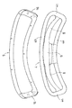
【図2】 フレーム及び保護フレームの斜視図である。
【図3】 フレーム及び保護フレームの断面図である。
【図4】 フレーム及び保護フレームを上から見た図である。
【図5】 図1のV−V線矢視断面図である。
【図6】 図1のVI−VI線矢視断面図である。
【図7】 製造方法の各段階を示し、(a)はコーキング材を充填塗布した図、(b)は傾斜面にてネットの縁部を仮止めした図、(c)は加熱した状態の図、(d)は徐冷後の図である。
【図8】(a)、(b)及び(c)は共に従来例を示す図である。
【符号の簡単な説明】
1 身体支持装置の一例としての椅子
2 座体
3 背凭
4 フレーム
5 保護フレーム
6 ネット
4 保護エッジ
12 凹溝
13 フレームの表面のネット載置面
14 フレームの外周の傾斜面
15 コーキング材
17 仮止め部[0001]
BACKGROUND OF THE INVENTION
The present invention relates to a body support device such as a chair and a method for manufacturing the same.
[0002]
[Prior art]
As one form of chair, there is a structure in which a seat body and a backrest are structured such that a net-like seat is stretched on a frame such as a substantially rectangular frame, and this type of chair is generally called a net chair (or net chair). Yes.
[0003]
FIG. 8 shows a conventional example of means for fixing the net to the frame constituting the chair body. Of these, the example shown in FIG. 8 (a) and disclosed in JP-A-8-507935 is that, when the
[0004]
Further, in the example shown in FIG. 8B, the
[0005]
Further, in the example shown in FIG. 8C, an
[0006]
[Problems to be solved by the invention]
As shown in FIG. 8 (a), the material embedded by insert molding is stretched in the space on the inner diameter side of the
[0007]
Similarly, in the case where the
[0008]
On the other hand, in the case where the
[0009]
In any case, since the
[0010]
Conventionally, when the manufacturing method shown in FIG. 8A is employed, tension is applied to the
[0011]
An object of the present invention is to provide a body support device such as a chair that solves such a problem, and to provide a method by which such a device can be manufactured at low cost.
[0012]
[Means for Solving the Problems]
In order to achieve the above object, a body support device such as a chair of the invention of claim 1 is a synthetic sheet in which a sheet made of a woven or net-like material having elasticity for receiving a human body and the sheet is stretched on the surface side. a resin frame-shaped frame provided with a protective frame for covering the outer peripheral surface of the frame, by forming the enclosed and the inner diameter side space by the frame, supported on the frame body of the person via the sheet A body support device configured to be configured so that a cross-sectional shape on the front surface side of the outer peripheral surface of the frame is formed in a convex curve shape, while a radially outer portion on the back surface side of the outer peripheral surface of the frame An annular groove is provided so as to extend over the entire circumference of the frame. Of the radially outer portion of the frame, on the opposite side of the convex curved surface across the groove, the back of the frame is provided. The sheet has an inclined surface that is inclined so as to approach the inner diameter side of the frame, and the edge of the sheet is bonded and fixed to the concave groove along the outer peripheral surface of the surface side of the frame with a caulking material. The protective frame having a substantially L-shaped cross section fixed from the back side of the frame is configured to cover the groove, the inclined surface, and the edge of the sheet .
[0013]
According to a second aspect of the present invention, in the body support device such as a chair according to the first aspect, both the frame and the seat are made of a thermoplastic synthetic resin that can be welded to each other, and an edge portion of the seat is formed in the concave groove. It is fixed to the frame by a filled caulking material and welding performed on the inclined surface, and the protective frame is screwed to the back surface following the inclined surface of the frame .
[0014]
The invention according to claim 3 is the body support device such as the chair according to claim 1 or 2, wherein when the frame is a frame for the back of the chair, the frame is an upper beam. a lower beam, by the left and right sides beam connecting the right and left side ends of the upper and lower beams concatenated formed integrally with the annular, and formed in arcuate shape of the left and right sides beam in side view, from the frame Also , the back side of the person supported by the seat located on the inner diameter side is configured not to contact the upper beam.
[0015]
Furthermore, the invention according to
[0016]
Furthermore, the invention according to
[0017]
DETAILED DESCRIPTION OF THE INVENTION
Next, an embodiment of the present invention will be described with reference to the drawings. FIG. 1 is a perspective view of a chair 1 having a
[0018]
FIG. 2 is a perspective view of the dorsal fin 3. As shown in FIG. 1 and FIG. 2, the dorsal fin 3 has a
[0019]
2, 3, and 4, the
[0020]
The sheet made of elastic fabric or net-like material (the
[0021]
As can be understood from FIGS. 5 and 6, the cross-sectional shapes of the upper and
[0022]
Similarly, as shown in FIGS. 5 and 6, the
[0023]
Next, a manufacturing method in which the
[0024]
First, the
[0025]
Next, the net 6 was covered from the surface side of the frame 4 (net support surface 13) so as to cover the space which is the inner diameter portion from the frame of the
[0026]
Next, the
[0027]
As described above, the cooling may be allowed to stand at room temperature for slow cooling, or may be positively cooled with cool air at a suitably low temperature.
[0028]
When the dough is manufactured by such a method, the net 4 (seat) is not unevenly stretched or wrinkled on the
[0029]
The present invention can be embodied in various ways other than the above embodiment. For example, when applying to a chair, it cannot be overemphasized that it can apply not only to a backrest but to a seat. In addition to a chair, the present invention can be applied to various body support devices such as a bed and a stretcher.
[0030]
[Operation and effect of the invention]
As described in detail above, the body support device such as the chair of the invention of claim 1 is a sheet made of a woven or net-like material having elasticity for receiving a human body, and the sheet is stretched on the surface side. a synthetic resin frame-shaped frame provided with a protective frame for covering the outer peripheral surface of the frame, by forming the enclosed and the inner diameter side space by the frame, the body of the person in the frame through the sheet A body support device configured to be supported, wherein a cross-sectional shape on the front surface side of the outer peripheral surface of the frame is formed in a convex curve shape, and a radially outer portion on the back surface side of the outer peripheral surface of the frame. The annular groove is provided so as to extend over the entire circumference of the frame, and of the radially outer portion of the frame, the back surface of the frame is located on the opposite side of the convex curved surface across the groove. It has an inclined surface that inclines so as to approach the inner diameter side of the frame as it approaches, and the edge of the sheet is bonded and fixed to the concave groove along the outer peripheral surface on the surface side of the frame with a caulking material, The protective frame having a substantially L-shaped cross section fixed from the back side of the frame is configured to cover the recessed groove portion, the inclined surface, and the edge portion of the sheet .
[0031]
Therefore, since the edge of the sheet is bent with respect to the wide surface of the frame, the tensile force acting on the sheet does not directly act on the fixing part (coking part) with the frame. There is an effect that it is possible to relieve the tensile force acting on the location and improve the attachment strength of the seat.
[0032]
In addition, since a protective frame is disposed on the outer periphery of the frame so as to cover the edge of the seat, even if other furniture collides with the frame, the edge of the seat is damaged by the other furniture. There is also an effect that the frame does not damage other furniture.
[0033]
According to a second aspect of the present invention, in the body support device such as a chair according to the first aspect, both the frame and the seat are made of a thermoplastic synthetic resin that can be welded to each other, and an edge portion of the seat is formed in the concave groove. It is fixed to the frame by a filled caulking material and welding performed on the inclined surface, and the protective frame is screwed to the back surface following the inclined surface of the frame .
[0034]
Thus, since the caulking material filled in the groove provided on the outer surface of the frame on the outer surface of the frame is fixed to the frame by the welding performed on the inclined surface adjacent thereto, the sheet is fixed to the frame ( It is possible to provide a body support portion having a high strength and a strong tension. In addition, the protective frame covers the caulking material and the welded portion, so that the appearance can be improved.
[0035]
The invention according to claim 3 is the body support device such as the chair according to
[0036]
With this configuration, when the back side of the drowning person is supported by the seat stretched on the inner diameter side of the back frame, the upper beam is located on the rear side away from the back side. The back side of the person drowning, the neck, etc. are not in direct contact with each other, and the sitting comfort is improved.
[0037]
Furthermore, the invention according to
[0038]
Furthermore, the invention according to
[0039]
According to this manufacturing method, no unevenness or wrinkles of the sheet is generated on the frame, and the sheet stretched in the space of the inner diameter portion of the frame forms a three-dimensional curved surface and fits well to the contact surface of the supporting person. can do. Furthermore, since it is not necessary to use an expensive molding die for forming the three-dimensional curved surface of the sheet, there is a remarkable effect that the manufacturing cost can be greatly reduced.
[Brief description of the drawings]
FIG. 1 is a perspective view of a chair.
FIG. 2 is a perspective view of a frame and a protective frame.
FIG. 3 is a cross-sectional view of a frame and a protective frame.
FIG. 4 is a top view of a frame and a protection frame.
FIG. 5 is a cross-sectional view taken along line VV in FIG. 1;
6 is a cross-sectional view taken along line VI-VI in FIG.
FIG. 7 shows each stage of the manufacturing method, (a) is a figure in which a caulking material is filled and applied, (b) is a figure in which the edge of the net is temporarily fixed on an inclined surface, and (c) is in a heated state. The figure (d) is a figure after slow cooling.
FIGS. 8A, 8B, and 8C are diagrams showing a conventional example.
[Brief description of symbols]
DESCRIPTION OF SYMBOLS 1 Chair as an example of
Claims (5)
前記フレームの外周面のうち表面側の断面形状を凸湾曲状に形成する一方、
前記フレームの外周面のうち裏面側における半径外側部位には、環状の凹溝が、フレームの全周にわたって延びるように設けられており、
前記フレームの半径外側部位のうち、前記凹溝を挟み前記凸湾曲状の表面と反対側には前記フレームの裏面に近づくに従って当該フレームの内径側に近づくように傾斜する傾斜面を有し、
前記シートの縁部が、前記フレームの表面側の外周面に沿って前記凹溝にコーキング材にて接着・固定され、
前記フレームの裏面側から固定した断面略L字状の前記保護フレームにて前記凹溝部と前記傾斜面と前記シートの縁部とを覆うように構成したことを特徴とする椅子等の身体支持装置。A sheet made of a woven or net-like material having elasticity for receiving a human body, a synthetic resin frame-like frame in which the sheet is stretched on the surface side, and a protective frame covering the outer peripheral surface of the frame and which, by constituting a fenced inner diameter side space in the frame, the human body is a constructed body support device to be supported by the frame via the sheet,
While forming the cross-sectional shape on the surface side of the outer peripheral surface of the frame into a convex curve,
An annular groove is provided on the radially outer portion on the back side of the outer peripheral surface of the frame so as to extend over the entire periphery of the frame.
Of the radially outer part of the frame, on the opposite side of the convex curved surface across the concave groove, there is an inclined surface that is inclined to approach the inner diameter side of the frame as it approaches the back surface of the frame,
The edge of the sheet is bonded and fixed to the concave groove along the outer peripheral surface on the surface side of the frame with a caulking material,
A body support device such as a chair, characterized in that the groove, the inclined surface, and the edge of the seat are covered with the protective frame having a substantially L-shaped cross section fixed from the back side of the frame. .
前記シートの縁部が、前記凹溝に充填したコーキング材と、前記傾斜面において行った溶着とによって前記フレームに固定され、
前記保護フレームを前記フレームの前記傾斜面に続く裏面に対してネジ締着したことを特徴とする請求項1に記載した椅子等の身体支持装置。Both the frame and the sheet are made of a thermoplastic synthetic resin that can be welded together,
The edge of the sheet is fixed to the frame by the caulking material filled in the concave groove and the welding performed on the inclined surface ,
The body support device for a chair or the like according to claim 1, wherein the protective frame is screwed to a back surface that follows the inclined surface of the frame .
前記フレームの外周面のうち裏面側における半径外側部位には、環状の凹溝が、フレームの全周にわたって延びるように設け、
前記環状の凹溝に、前記シートの縁部と共に熱可塑性のコーキング材を充填固化し、
次いで、人の身体を受ける弾性を有する織物またはネット状素材からなるシートの縁部を、前記フレームの凸湾曲状の表面側から前記凹溝を超えて裏面側の傾斜面にて融着させて仮止めし、
次いで、前記フレーム及びシートを適宜時間加熱することにより、前記コーキング材を一旦溶融させてのち冷却し、前記シートに3次曲面となる張力付与して前記フレームに固定し、
その後前記フレームの裏面側から断面略L字状の保護フレームをネジ締着により固定したことを特徴とする椅子等の身体支持装置の製造方法。 While forming the cross-sectional shape on the surface side out of the outer peripheral surface of the frame-shaped frame made of synthetic resin into a convex curve,
An annular groove is provided on the radially outer side of the outer peripheral surface of the frame on the back side so as to extend over the entire periphery of the frame,
Filling and solidifying the annular concave groove with a thermoplastic caulking material together with the edge of the sheet,
Next, the edge of the sheet made of a woven or net-like material having elasticity to receive the human body is fused on the inclined surface on the back surface side from the convex curved surface side of the frame beyond the concave groove. Temporarily fix,
Next, by heating the frame and the sheet for an appropriate period of time, the caulking material is once melted and then cooled, and tension is applied to the sheet to form a third-order curved surface and fixed to the frame.
Thereafter, a protective frame having a substantially L-shaped cross section is fixed from the back side of the frame by screw fastening .
Priority Applications (1)
| Application Number | Priority Date | Filing Date | Title |
|---|---|---|---|
| JP2001190106A JP3852677B2 (en) | 2001-06-22 | 2001-06-22 | Body support device such as chair and manufacturing method thereof |
Applications Claiming Priority (1)
| Application Number | Priority Date | Filing Date | Title |
|---|---|---|---|
| JP2001190106A JP3852677B2 (en) | 2001-06-22 | 2001-06-22 | Body support device such as chair and manufacturing method thereof |
Publications (2)
| Publication Number | Publication Date |
|---|---|
| JP2003000400A JP2003000400A (en) | 2003-01-07 |
| JP3852677B2 true JP3852677B2 (en) | 2006-12-06 |
Family
ID=19028925
Family Applications (1)
| Application Number | Title | Priority Date | Filing Date |
|---|---|---|---|
| JP2001190106A Expired - Fee Related JP3852677B2 (en) | 2001-06-22 | 2001-06-22 | Body support device such as chair and manufacturing method thereof |
Country Status (1)
| Country | Link |
|---|---|
| JP (1) | JP3852677B2 (en) |
Cited By (1)
| Publication number | Priority date | Publication date | Assignee | Title |
|---|---|---|---|---|
| US11337526B2 (en) * | 2018-04-19 | 2022-05-24 | Cramer Llc | Chair having pliable backrest and methods for same |
Families Citing this family (8)
| Publication number | Priority date | Publication date | Assignee | Title |
|---|---|---|---|---|
| CN1976609B (en) * | 2004-05-13 | 2011-12-21 | 休思乐公司 | Mesh chair component |
| KR100701417B1 (en) * | 2005-01-29 | 2007-03-30 | 이준구 | Mesh support plate and manufacturing method of the mesh support plate |
| KR100766561B1 (en) * | 2006-04-27 | 2007-10-11 | 텔코웨어 주식회사 | Implementation and System of Redundant Memory File System in Distributed Network Environment |
| JP5163148B2 (en) * | 2008-01-23 | 2013-03-13 | トヨタ紡織株式会社 | Net sheet and method of manufacturing the frame |
| JP5708211B2 (en) * | 2011-05-02 | 2015-04-30 | トヨタ自動車株式会社 | Seat backboard and vehicle seat using the same |
| JP5724815B2 (en) * | 2011-10-13 | 2015-05-27 | トヨタ自動車株式会社 | Resin seat backboard and vehicle seat |
| WO2017213229A1 (en) * | 2016-06-10 | 2017-12-14 | 株式会社岡村製作所 | Load support structure for chair, load support body for chair, and chair |
| JP6958211B2 (en) | 2017-10-12 | 2021-11-02 | トヨタ自動車株式会社 | Vehicle seat |
-
2001
- 2001-06-22 JP JP2001190106A patent/JP3852677B2/en not_active Expired - Fee Related
Cited By (1)
| Publication number | Priority date | Publication date | Assignee | Title |
|---|---|---|---|---|
| US11337526B2 (en) * | 2018-04-19 | 2022-05-24 | Cramer Llc | Chair having pliable backrest and methods for same |
Also Published As
| Publication number | Publication date |
|---|---|
| JP2003000400A (en) | 2003-01-07 |
Similar Documents
| Publication | Publication Date | Title |
|---|---|---|
| US6942300B2 (en) | Structure for mounting a net member to a frame for a seat or backrest of a chair | |
| JP3852677B2 (en) | Body support device such as chair and manufacturing method thereof | |
| US5788332A (en) | Seat unit and cushion | |
| CA2790537C (en) | Furniture and method of furniture component attachment | |
| JP4036418B2 (en) | Manufacturing method for chair seat or backrest | |
| WO2014147663A1 (en) | Office chair | |
| KR102782836B1 (en) | Sheet comprising suspension fabric having compression limiters | |
| JPS63122510A (en) | Method of molding composite material product | |
| WO2008126052A1 (en) | Human body supporting structure, particularly bicycle saddle and method of making same | |
| CN1279591A (en) | Seat having seat surface of planar elastic body | |
| JP2001224461A (en) | Chair | |
| JP4624858B2 (en) | Load bearing fabric assembly | |
| EP0816162B1 (en) | Vehicle seat element having a cover attached to a metallic framework | |
| JP4531697B2 (en) | Manufacturing method of structure that functions as seat, backrest, partition, etc. and structure manufactured by the method | |
| KR101163376B1 (en) | Seat and/or Backrest with Elastic Fiber Membrane and Manutacturing Method thereof | |
| JP3696419B2 (en) | Cushion body | |
| JP3654569B2 (en) | Manufacturing method of seat body in chair, etc. | |
| JP2002165672A (en) | Body support device for chair or the like | |
| JP3666559B2 (en) | Seat body in chair and the like and method for manufacturing the same | |
| JP2010188912A (en) | Belt-like cover of vehicle seat | |
| JP3666564B2 (en) | Production method and physical support of the body support such as a chair seat body | |
| JP4009704B2 (en) | Seat having a seating surface by a planar elastic body | |
| JP4009705B2 (en) | Seat having a seating surface by a planar elastic body | |
| JP2799969B2 (en) | Hanging member | |
| JPH11342039A (en) | Seat having seat surface by planar elastic body |
Legal Events
| Date | Code | Title | Description |
|---|---|---|---|
| A621 | Written request for application examination |
Free format text: JAPANESE INTERMEDIATE CODE: A621 Effective date: 20040930 |
|
| A977 | Report on retrieval |
Free format text: JAPANESE INTERMEDIATE CODE: A971007 Effective date: 20060523 |
|
| A131 | Notification of reasons for refusal |
Free format text: JAPANESE INTERMEDIATE CODE: A131 Effective date: 20060530 |
|
| A521 | Written amendment |
Free format text: JAPANESE INTERMEDIATE CODE: A523 Effective date: 20060721 |
|
| TRDD | Decision of grant or rejection written | ||
| A01 | Written decision to grant a patent or to grant a registration (utility model) |
Free format text: JAPANESE INTERMEDIATE CODE: A01 Effective date: 20060830 |
|
| A61 | First payment of annual fees (during grant procedure) |
Free format text: JAPANESE INTERMEDIATE CODE: A61 Effective date: 20060830 |
|
| R150 | Certificate of patent or registration of utility model |
Free format text: JAPANESE INTERMEDIATE CODE: R150 |
|
| FPAY | Renewal fee payment (event date is renewal date of database) |
Free format text: PAYMENT UNTIL: 20090915 Year of fee payment: 3 |
|
| FPAY | Renewal fee payment (event date is renewal date of database) |
Free format text: PAYMENT UNTIL: 20100915 Year of fee payment: 4 |
|
| FPAY | Renewal fee payment (event date is renewal date of database) |
Free format text: PAYMENT UNTIL: 20110915 Year of fee payment: 5 |
|
| FPAY | Renewal fee payment (event date is renewal date of database) |
Free format text: PAYMENT UNTIL: 20120915 Year of fee payment: 6 |
|
| FPAY | Renewal fee payment (event date is renewal date of database) |
Free format text: PAYMENT UNTIL: 20130915 Year of fee payment: 7 |
|
| LAPS | Cancellation because of no payment of annual fees |