JP3711111B2 - Linear motor - Google Patents
Linear motor Download PDFInfo
- Publication number
- JP3711111B2 JP3711111B2 JP2003014192A JP2003014192A JP3711111B2 JP 3711111 B2 JP3711111 B2 JP 3711111B2 JP 2003014192 A JP2003014192 A JP 2003014192A JP 2003014192 A JP2003014192 A JP 2003014192A JP 3711111 B2 JP3711111 B2 JP 3711111B2
- Authority
- JP
- Japan
- Prior art keywords
- core
- core member
- linear motor
- face
- stator
- Prior art date
- Legal status (The legal status is an assumption and is not a legal conclusion. Google has not performed a legal analysis and makes no representation as to the accuracy of the status listed.)
- Expired - Fee Related
Links
Images


Landscapes
- Iron Core Of Rotating Electric Machines (AREA)
- Linear Motors (AREA)
Description
【0001】
【発明の属する技術分野】
この発明は、リニアモータに係り、特にコイルが巻回される側の固定子または可動子の構造に関するものである。
【0002】
【従来の技術】
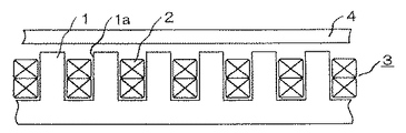
この種従来のリニアモータは、図16に示すように所定のピッチでスロット1aが形成された櫛歯状の鉄板を、多数枚積層してなる鉄心1にコイル2を装着して形成される固定子3と、この固定子3に対向し空隙を介して移動可能に設けられた可動子4とで構成されているが、図から明らかなようにスロット1aの上側開口部が広いので、コイル2によって進行磁界が発生されると、この進行磁界がピッチと等しい周期で振幅変調され、リニアモータの推力を打ち消す方向の力が発生して出力が低下するという問題が生じる。
このため、図17に示すようにスロット1aの上側開口部に突出部1bを設けた複数の鉄板を積層して固定子3を形成し、この突出部1bによりスロット1aの上側開口部を狭くして効果的に対処することも知られている。
【0003】
しかしながら、このようにスロット1aの上側開口部に突出部1bを設けると、スロット1aの上側開口部が狭くなるので、コイル2を巻回したり嵌め込む作業が著しく困難になるという問題を生じる。
そこで、例えば特開平6−165469号公報等では、図18に示すように鉄心5の各歯5aの先端両側に、切り欠き部5bを介して枝部5cをそれぞれ形成し、スロット5dにコイル6を巻回または嵌め込んだ後、図19に示すように切り欠き部5bを折り曲げて各歯5aの先端間を狭くすることが提案されている。
【0004】
【発明が解決しようとする課題】
従来のリニアモータは以上のように構成され、スロット5dにコイル6を巻回または嵌め込んだ後、切り欠き部を折り曲げて各歯5aの先端間を狭くすることにより、コイル6を巻回または嵌め込む作業を比較的容易にするとともに、出力が低下するという問題を解決している。
しかしながら、コイル6の巻回または嵌め込み時には、スロット5dの上側開口部が広くなっているとはいうものの、スロット5dの幅より広くなることはないので、コイル6を直巻きする場合にスロット5d内に巻線ノズル(図示せず)の通り道を確保する必要があるため、その分コイル6の巻線密度が低くなり、所定の容量を得るためには大形化し、又、予めボビン等にコイル6を巻回したものをスロット5d内に嵌め込むようにすれば、スロット5d内に巻線ノズルの通り道を確保する必要もなくなるため巻線密度を上げることは出来るが、各コイル6間を接続するための部品点数やその作業が増加してコストが増大する等の問題点があった。
【0005】
この発明は上記のような問題点を解消するためになされたもので、コイルの巻線密度を下げることなく直巻きができるようにして、小形化ならびにコストの低減が可能なリニアモータを提供することを目的とするものである。
【0006】
【課題を解決するための手段】
この発明に係るリニアモータは、固定子または可動子の一方に適用されるものであって、磁極テイースを有する複数のコア片を帯状に配列してなるコア部材を積層してなる積層ヨーク部材と、上記積層ヨーク部材の上記磁極テイースに巻回されるコイル部材とを備え、
上記コア部材は第1のコア部材及び第2のコア部材を重ね合わせてなり、
上記コア片は、配列方向の一端に凸状端面を有し他端に凹状端面を有し、上記第1のコア部材及び第2のコア部材それぞれの隣り合うコア片の上記凸状端面と上記凹状端面とが嵌合し、
上記第1のコア部材及び第2のコア部材は、上記第1のコア部材の凸状端面の向きと上記第2のコア部材の凸状端面の向きが逆方向になるように、かつ、上記第1のコア部材のコア片の凸状端面側の面と上記第2のコア部材の凸状端面側の面とが重なるようにし、
上記コア片の凸状端面側の面に、上記隣り合うコア片が上記凸状端面と上記凹状端面との嵌合部で屈曲可能とするとともに、積層方向の上記コア片を連結する連結手段を設けているものである。
【0007】
【発明の実施の形態】
実施の形態1.
以下、この発明の実施の形態を図に基づいて説明する。図1はこの発明の実施の形態1におけるリニアモータの構成を示す断面図、図2は図1における積層ヨーク部材のコア片間を連結する連結手段の構成を示し、(A)は平面図、(B)は(A)における線A−Aに沿った断面を示す断面図、図3は図1における固定子の構成を示す平面図、図4は図3における固定子のコイルの巻線方法を説明するための図、図5および図6はこの発明の実施の形態1におけるリニアモータの要部の構成が図1におけるとはそれぞれ異なる構成を示す断面図である。
【0008】
図において、7は磁性材料でなる板状のコア片で、一端側裏面に連結手段としての凹部7aおよび凸部7bが形成されるとともに、その凸状端面7cはこれら凹部7aおよび凸部7bの中心を中心とした円弧状に形成され、他端側には相隣なるコア片7の凸状端面7cと嵌合可能な凹状端面7dが形成されており、中央部から外方に磁極テイース8がそれぞれ突設されている。9は複数のコア片7が各凸状端面7c、凹状端面7dを介して配列された第1のコア部材である。
【0009】
10は各コア片7が第1のコア部材9とは長手方向に互い違いに配列され、第1のコア部材9と共に積層ヨーク部材11を構成する第2のコア部材で、第1のコア部材9と交互に積層され積層方向に相隣なるコア片7同士の凹部7aおよび凸部7bが嵌合されることにより回転自在に連結されているとともに、図2から明らかなように、第1のコア部材9の凸状端面7c側面と破線で示す第2のコア部材10の凸状端面7dとが重なっており、この重なりによって磁気抵抗が低減される。なお、最上層となるコア片7には凸部7bが嵌合可能な穴部7eが形成されている。12は各磁極テイース8に絶縁ボビン13を介して巻回されたコイル、14は積層ヨーク部材11を固定側に保持する保持部材で、これら7ないし14で固定子15を構成している。16は固定子15の各磁極テイース8の先端と所定の間隙、すなわちエアギャップを介して配設され、固定子15と対向する側に所定のピッチで複数の永久磁石17が取り付けられた可動子、18はノズル19を介してコイル12を巻回する巻線機、20は駆動軸21により回転駆動される巻線治具である。
【0010】
次に、上記のように構成された実施の形態1におけるリニアモータの製造方法について説明する。
まず、第1および第2のコア部材9、10をプレス打ち抜きにより交互に打ち抜いて金型内で順次積層し、各コア片7の積層方向で相対向する凹部7aおよび凸部7b同士が嵌合されるとともに、抜きかしめがなされて一体化され図2(A)に示すように積層ヨーク部材11が構成される。そして、この積層ヨーク部材11の各磁極テイース8に絶縁ボビン13をそれぞれ装着する。
【0011】
次に、図4に示すようにこの積層ヨーク部材11を、駆動軸21により回転駆動される巻線治具20に装着する。すると、巻線治具20に装着された各コア片7同士は連結手段としての凹部7aおよび凸部7bの回転により屈曲し、各磁極テイース8はその先端が放射状に拡開される。次いで、このように各磁極テイース8の先端が拡開された状態で、巻線機18によりノズル19を介して各磁極テイース8に巻線が行われコイル12が形成される。
【0012】
すると、駆動軸21の回転により巻線治具20が駆動され、次の新しいコア片7が順次巻線治具20に装着され、再び巻線が行われてコイル12が形成される。以下同様の動作が繰り返されて図3に示すような状態に組み立てられた後、積層ヨーク部材11の各コア片7側を保持部材14で保持固定して固定子15が構成され、各磁極テイース8の先端側にエアギャップを介して可動子16を配置することによりリニアモータが完成する。
そして、各コイル12を励磁することにより発生する進行磁界によって可動子16に推力が発生し、この推力によって可動子16に搭載された被搬送物が搬送される。
【0013】
このように上記実施の形態1によれば、連結手段としての凹部7aおよび凸部7bを回転させて各コア片7間を屈曲させ、各磁極テイース8を放射状に拡開した状態で巻線を行いコイル12を形成するようにしているので、直巻きとしてもノズル19の通り道を確保する必要など無くなり、巻線密度を十分に上げることができるため、小形化ならびにコストの低減が可能となる。又、巻線後に屈曲された各コア片7間を元に戻し正常な状態にしているので、図5に示すように各磁極テイース8の先端間の開口幅を狭くすることができ、場合によっては図6に示すように各磁極テイース8の先端同士を当接させて開口幅を無くすこともできるため、可動子16の動きを滑らかにすることが可能となる。
【0014】
実施の形態2.
図7はこの発明の実施の形態2におけるリニアモータの固定子の構成を示す断面図、図8はこの発明の実施の形態2におけるリニアモータの固定子の図7に示すとは異なる構成を示す断面図である。
図において、上記実施の形態1におけると同様な部分は同一符号を付して説明を省略する。
【0015】
22は磁性材料でなり後述の保持部材と対応する側にそれぞれアリ溝22aが形成された複数のコア片で、連結手段としての薄肉部23を介して屈曲可能に連結されている。24は各コア片22から外方に突出して形成される磁極テイース、25はこれら22ないし24で形成されるコア部材で、所定の枚数が積層され例えば抜きかしめ等によって一体化されることにより積層ヨーク部材26を構成している。そして、積層ヨーク部材26の各磁極テイース24には絶縁ボビン13を介してコイル12がそれぞれ巻回されている。27は各コア片22のアリ溝22aと対応する位置に、アリ溝22aと嵌合可能な複数の突起27aが形成された保持部材で、各突起27aをアリ溝22aと嵌合させることにより、積層ヨーク部材26を保持固定し固定子28を構成している。
【0016】
このように上記実施の形態2によれば、連結手段としての薄肉部23を折曲させて各コア片22間を屈曲できるようにしているので、上記実施の形態1におけると同様に、各磁極テイース24を放射状に拡開した状態で巻線を行いコイル12を形成することができるため、巻線密度を十分に上げ小形化ならびにコストの低減が可能であることは勿論のこと、保持部材27の突起27aをコア片22のアリ溝22aに嵌合させて積層ヨーク部材26を固定保持しているので、機械的強度を向上させることが可能となる。
【0017】
なお、図7における構成では、コア片22側にアリ溝22aを、保持部材27側に突起27aをそれぞれ形成した場合について説明したが、図8に示すようにコア片22側に突起22bを、保持部材27側にアリ溝27bをそれぞれ形成するようにしても良く上記と同様の効果を発揮し得ることは言うまでもない。
【0018】
実施の形態3.
図9はこの発明の実施の形態3におけるリニアモータの固定子の構成を示す断面図である。
図において、上記実施の形態2におけると同様な部分は同一符号を付して説明を省略する。29は例えばポリブチレンテレフタレートのような熱可塑性樹脂や、エポキシ樹脂のような熱硬化性樹脂等の樹脂により形成された保持部材で、この樹脂は保持部材29の形成時に各磁極テイース24に巻回されたコイル12近傍に存在する隙間にも埋め込まれ、コイル12および積層ヨーク部材26と共に一体にモールド成形されている。
【0019】
このように上記実施の形態3によれば、保持部材29を形成する樹脂でコイル12および積層ヨーク部材26を一体にモールド成形しているので、組立作業性および機械的強度の向上を図ることが可能になる。
【0020】
実施の形態4.
図10はこの発明の実施の形態4におけるリニアモータの固定子の要部の構成を示す断面図、図11は図10におけるリニアモータの固定子の要部の構成を示す背面図、図12はこの発明の実施の形態4におけるリニアモータの固定子と可動子の配置関係を示す平面図である。
図において、上記各実施の形態1ないし3におけると同様な部分は同一符号を付して説明を省略する。
【0021】
30は磁性材料でなる板状のコア片で、一端に突出部30aおよび他端に隣接するコア片30の突出部30aと回転可能に嵌合することにより関節形状を形成する窪み部30bが設けられている。31は各コア片30から外方に突出して形成される磁極テイースで、絶縁ボビン13を介してコイル12がそれぞれ巻回されている。32は各コア片30を各突出部30aおよび窪み部30bを嵌合させることにより所定の枚数連結して形成されるコア部材、33はこのコア部材32を所定の数だけ積層し、例えば抜きかしめ等により一体化して形成される積層ヨーク部材であり、図11に示すように各突出部30a、窪み部30bの各嵌合部を所定量ずつ摺動させることにより、各コア片30をコア部材32の積層方向に順次ずらして配置し、保持部材(図示せず)により固定保持して固定子34が構成される。
【0022】
このように上記実施の形態4によれば、各突出部30aおよび窪み部30bの各嵌合部を所定量ずつ摺動させることにより、各コア片30をコア部材32の積層方向に順次ずらして配置するようにしているので、例えば図12に示すように、可動子35に対して固定子34を所定の角度αだけ傾けて配置することにより、容易にスキューを与えることができ、コギングの発生を効果的に抑制することが可能になる。
【0023】
実施の形態5.
図13はこの発明の実施の形態5におけるリニアモータの固定子の要部の構成を示す断面図、図14は図13におけるリニアモータの固定子の要部の構成を示す背面図、図15はこの発明の実施の形態5におけるリニアモータの固定子と可動子の配置関係を示す平面図である。
図において、上記各実施の形態1ないし4におけると同様な部分は同一符号を付して説明を省略する。
【0024】
36は磁性材料でなり所定の枚数積層された板状のコア片で、最上、下層の両コア片36は連結手段としての薄肉部36aを介して屈曲可能に連結されており、図14に示すように最上、下層の両コア片36の各薄肉部36aを積層方向に折曲させることにより、各コア片36を積層方向に順次ずらして配置し、保持部材(図示せず)により固定保持して固定子37が構成される。
【0025】
このように上記実施の形態5によれば、最上、下層の両コア片36の各薄肉部36aを積層方向に折曲させることにより、各コア片36を積層方向に順次ずらして配置するようにしているので、例えば図15に示すように、上記実施の形態4におけると同様に可動子35に対して固定子37を所定の角度αだけ傾けて配置することにより、容易にスキューを与えることができ、コギングの発生を効果的に抑制することが可能になる。
【0026】
なお、上記各実施の形態1ないし5においては、固定子側に巻線が施された構成について説明したが、これに限定されるものではなく可動子側に巻線が施された構成のものに適用しても、上記とそれぞれ同様の効果を発揮し得ることは言うまでもない。
【0027】
【発明の効果】
以上のように、この発明に係るリニアモータによれば、固定子または可動子の一方に適用されるものであって、磁極テイースを有する複数のコア片を帯状に配列してなるコア部材を積層してなる積層ヨーク部材と、上記積層ヨーク部材の上記磁極テイースに巻回されるコイル部材とを備え、
上記コア部材は第1のコア部材及び第2のコア部材を重ね合わせてなり、
上記コア片は、配列方向の一端に凸状端面を有し他端に凹状端面を有し、上記第1のコア部材及び第2のコア部材それぞれの隣り合うコア片の上記凸状端面と上記凹状端面とが嵌合し、
上記第1のコア部材及び第2のコア部材は、上記第1のコア部材の凸状端面の向きと上記第2のコア部材の凸状端面の向きが逆方向になるように、かつ、上記第1のコア部材のコア片の凸状端面側の面と上記第2のコア部材の凸状端面側の面とが重なるようにし、
上記コア片の凸状端面側の面に、上記隣り合うコア片が上記凸状端面と上記凹状端面との嵌合部で屈曲可能とするとともに、積層方向の上記コア片を連結する連結手段を設けているものであるので、コイルの巻線密度を下げることなく直巻きができるようにして、小形化ならびにコストの低減が可能なリニアモータを提供することができるとともに、配列したコア片間の磁気抵抗を低減することができる。
【図面の簡単な説明】
【図1】 この発明の実施の形態1におけるリニアモータの構成を示す断面図である。
【図2】 図1における積層ヨーク部材のコア片間を連結する連結手段の構成を示し、(A)は平面図、(B)は(A)における線A−Aに沿った断面を示す断面図である。
【図3】 図1における固定子の構成を示す平面図である。
【図4】 図3における固定子のコイルの巻線方法を説明するための図である。
【図5】 この発明の実施の形態1におけるリニアモータの要部の図1に示すとは異なる構成を示す断面図である。
【図6】 この発明の実施の形態1におけるリニアモータの要部の図1に示すとはさらに異なる構成を示す断面図である。
【図7】 この発明の実施の形態2におけるリニアモータの固定子の構成を示す断面図である。
【図8】 この発明の実施の形態2におけるリニアモータの固定子の図7に示すとは異なる構成を示す断面図である。
【図9】 この発明の実施の形態3におけるリニアモータの固定子の構成を示す断面図である。
【図10】 この発明の実施の形態4におけるリニアモータの固定子の要部の構成を示す断面図である。
【図11】 図10におけるリニアモータの固定子の要部の構成を示す背面図である。
【図12】 この発明の実施の形態4におけるリニアモータの固定子と可動子の配置関係を示す平面図である。
【図13】 この発明の実施の形態5におけるリニアモータの固定子の要部の構成を示す断面図である。
【図14】 図13におけるリニアモータの固定子の要部の構成を示す背面図である。
【図15】 この発明の実施の形態5におけるリニアモータの固定子と可動子の配置関係を示す平面図である。
【図16】 従来のリニアモータの構成を示す断面図である。
【図17】 従来のリニアモータの固定子の鉄心の図16に示すとは異なる構成を示す平面図である。
【図18】 従来のリニアモータの固定子の鉄心の図16に示すとはさらに異なる構成を示す平面図である。
【図19】 図18に示す固定子の鉄心が用いられたリニアモータの構成を示す断面図である。
【符号の説明】
7,22,30,36 コア片、7a 凹部、7b 凸部、
7c 凸状端面、7d 凹状端面、22a,27b アリ溝、
22b,27a 突起、30a 突出部、30b 窪み部、36a 薄肉部、
8,24,31 磁極テイース、9 第1のコア部材、10 第2のコア部材、
11,26,33 積層ヨーク部材、12 コイル、13 絶縁ボビン、
14,27,29 保持部材、15,28,34,37 固定子、
16,35 可動子、18 巻線機、19 ノズル、20 巻線治具、
23,36a 薄肉部、25,32 コア部材。[0001]
BACKGROUND OF THE INVENTION
The present invention relates to a linear motor, and more particularly to a structure of a stator or a mover on a side around which a coil is wound.
[0002]
[Prior art]
As shown in FIG. 16, this type of conventional linear motor is formed by attaching a
For this reason, as shown in FIG. 17, the
[0003]
However, if the
Therefore, for example, in JP-A-6-165469, etc., as shown in FIG. 18,
[0004]
[Problems to be solved by the invention]
The conventional linear motor is configured as described above. After winding or fitting the coil 6 in the
However, when the coil 6 is wound or fitted, the upper opening of the
[0005]
The present invention has been made to solve the above-described problems, and provides a linear motor that can be reduced in size and cost by enabling direct winding without lowering the winding density of the coil. It is for the purpose.
[0006]
[Means for Solving the Problems]
A linear motor according to the present invention is applied to one of a stator and a mover, and a laminated yoke member formed by laminating core members formed by arranging a plurality of core pieces having magnetic pole teeth in a strip shape. A coil member wound around the magnetic pole teeth of the laminated yoke member,
The core member is formed by overlapping the first core member and the second core member,
The core piece has a convex end face at one end in the arrangement direction and a concave end face at the other end, and the convex end face of the adjacent core piece of each of the first core member and the second core member, and the above The concave end face is fitted,
The first core member and the second core member are arranged so that the direction of the convex end surface of the first core member is opposite to the direction of the convex end surface of the second core member, and The surface on the convex end face side of the core piece of the first core member and the surface on the convex end face side of the second core member overlap,
A connecting means for connecting the core pieces in the stacking direction to the surface on the convex end face side of the core pieces, wherein the adjacent core pieces can be bent at a fitting portion between the convex end face and the concave end face. It is provided.
[0007]
DETAILED DESCRIPTION OF THE INVENTION
Embodiments of the present invention will be described below with reference to the drawings. 1 is a cross-sectional view showing a configuration of a linear motor according to
[0008]
In the figure,
[0009]
Reference numeral 10 denotes a second core member in which the
[0010]
Next, the manufacturing method of the linear motor in
First, the first and second core members 9 and 10 are alternately punched by press punching and sequentially stacked in the mold, and the
[0011]
Next, as shown in FIG. 4, the laminated
[0012]
Then, the winding
Then, a thrust is generated in the
[0013]
As described above, according to the first embodiment, the
[0014]
7 is a cross-sectional view showing the configuration of the stator of the linear motor according to the second embodiment of the present invention, and FIG. 8 shows a configuration different from that shown in FIG. 7 of the stator of the linear motor according to the second embodiment of the present invention. It is sectional drawing.
In the figure, the same parts as those in the first embodiment are denoted by the same reference numerals, and the description thereof is omitted.
[0015]
[0016]
As described above, according to the second embodiment, the thin-
[0017]
In the configuration in FIG. 7, the
[0018]
FIG. 9 is a cross-sectional view showing the configuration of the stator of the linear motor according to
In the figure, the same parts as those in the second embodiment are denoted by the same reference numerals, and the description thereof is omitted.
[0019]
As described above, according to the third embodiment, since the
[0020]
10 is a cross-sectional view showing the configuration of the main part of the stator of the linear motor according to
In the figure, the same parts as those in the first to third embodiments are denoted by the same reference numerals, and the description thereof is omitted.
[0021]
[0022]
As described above, according to the fourth embodiment, the
[0023]
13 is a cross-sectional view showing the configuration of the main part of the stator of the linear motor according to
In the figure, the same parts as those in the first to fourth embodiments are denoted by the same reference numerals, and the description thereof is omitted.
[0024]
[0025]
As described above, according to the fifth embodiment, the
[0026]
In each of the first to fifth embodiments, the configuration in which the winding is provided on the stator side has been described. However, the configuration is not limited to this, and the configuration in which the winding is provided on the mover side is described. It goes without saying that even if applied to the above, the same effects as described above can be exhibited.
[0027]
【The invention's effect】
As described above, according to the linear motor according to the present invention, the core member is applied to one of the stator and the mover, and is formed by stacking the core members formed by arranging a plurality of core pieces having magnetic pole teeth. A laminated yoke member, and a coil member wound around the magnetic pole teeth of the laminated yoke member,
The core member is formed by overlapping the first core member and the second core member,
The core piece has a convex end face at one end in the arrangement direction and a concave end face at the other end, and the convex end face of the adjacent core piece of each of the first core member and the second core member, and the above The concave end face is fitted,
The first core member and the second core member are arranged such that the direction of the convex end surface of the first core member is opposite to the direction of the convex end surface of the second core member, and The surface on the convex end face side of the core piece of the first core member and the surface on the convex end face side of the second core member overlap,
A connecting means for connecting the core pieces in the stacking direction to the surface on the convex end face side of the core pieces, wherein the adjacent core pieces can be bent at a fitting portion between the convex end face and the concave end face. Therefore, it is possible to provide a linear motor that can be reduced in size and reduced in cost by enabling direct winding without reducing the winding density of the coil, and between the arranged core pieces. Magnetic resistance can be reduced.
[Brief description of the drawings]
FIG. 1 is a cross-sectional view showing a configuration of a linear motor according to
2 shows a configuration of a connecting means for connecting the core pieces of the laminated yoke member in FIG. 1, (A) is a plan view, and (B) is a cross section showing a cross section along line AA in (A). FIG.
FIG. 3 is a plan view showing a configuration of a stator in FIG. 1;
4 is a diagram for explaining a winding method of a stator coil in FIG. 3; FIG.
FIG. 5 is a cross-sectional view showing a configuration different from that shown in FIG. 1 of the main part of the linear motor according to
FIG. 6 is a cross-sectional view showing a further different configuration from that shown in FIG. 1 of the main part of the linear motor according to the first embodiment of the present invention.
FIG. 7 is a cross sectional view showing a configuration of a stator of a linear motor according to
FIG. 8 is a cross-sectional view showing a configuration different from that shown in FIG. 7 of the stator of the linear motor according to the second embodiment of the present invention.
FIG. 9 is a sectional view showing a configuration of a stator of a linear motor according to
FIG. 10 is a cross-sectional view showing a configuration of a main part of a stator of a linear motor according to
11 is a rear view showing the configuration of the main part of the stator of the linear motor in FIG.
FIG. 12 is a plan view showing the positional relationship between a stator and a mover of a linear motor according to
FIG. 13 is a cross sectional view showing a configuration of a main part of a stator of a linear motor according to a fifth embodiment of the present invention.
14 is a rear view showing the configuration of the main part of the stator of the linear motor in FIG. 13. FIG.
FIG. 15 is a plan view showing a positional relationship between a stator and a mover of a linear motor according to
FIG. 16 is a cross-sectional view showing a configuration of a conventional linear motor.
FIG. 17 is a plan view showing a configuration different from that shown in FIG. 16 of the iron core of the stator of the conventional linear motor.
18 is a plan view showing a further different configuration from that shown in FIG. 16 of the iron core of the stator of the conventional linear motor.
19 is a cross-sectional view showing a configuration of a linear motor using the stator iron core shown in FIG. 18;
[Explanation of symbols]
7, 22, 30, 36 core piece, 7a concave portion, 7b convex portion,
7c Convex end face, 7d Concave end face, 22a, 27b Dovetail groove,
22b, 27a protrusion, 30a protrusion, 30b recess, 36a thin-walled part,
8, 24, 31 magnetic pole teeth, 9 first core member, 10 second core member,
11, 26, 33 Laminated yoke members, 12 coils, 13 insulating bobbins,
14, 27, 29 holding member, 15, 28, 34, 37 stator,
16, 35 mover, 18 winding machine, 19 nozzle, 20 winding jig,
23, 36a Thin portion, 25, 32 core member.
Claims (2)
上記コア部材は第1のコア部材及び第2のコア部材を重ね合わせてなり、
上記コア片は、配列方向の一端に凸状端面を有し他端に凹状端面を有し、上記第1のコア部材及び第2のコア部材それぞれの隣り合うコア片の上記凸状端面と上記凹状端面とが嵌合し、
上記第1のコア部材及び第2のコア部材は、上記第1のコア部材の凸状端面の向きと上記第2のコア部材の凸状端面の向きが逆方向になるように、かつ、上記第1のコア部材のコア片の凸状端面側の面と上記第2のコア部材の凸状端面側の面とが重なるようにし、
上記コア片の凸状端面側の面に、上記隣り合うコア片が上記凸状端面と上記凹状端面との嵌合部で屈曲可能とするとともに、積層方向の上記コア片を連結する連結手段を設けていることを特徴とするリニアモータ。A laminated yoke member that is applied to one of the stator and the movable element and is formed by laminating a core member in which a plurality of core pieces having magnetic pole teeth are arranged in a strip shape, and the magnetic pole of the laminated yoke member A coil member wound around the tee,
The core member is formed by overlapping the first core member and the second core member,
The core piece has a convex end face at one end in the arrangement direction and a concave end face at the other end, and the convex end face of the adjacent core piece of each of the first core member and the second core member, and the above The concave end face is fitted,
The first core member and the second core member are arranged so that the direction of the convex end surface of the first core member is opposite to the direction of the convex end surface of the second core member, and The surface on the convex end face side of the core piece of the first core member and the surface on the convex end face side of the second core member overlap,
A connecting means for connecting the core pieces in the stacking direction to the surface on the convex end face side of the core pieces, wherein the adjacent core pieces can be bent at a fitting portion between the convex end face and the concave end face. A linear motor characterized by being provided.
Priority Applications (1)
| Application Number | Priority Date | Filing Date | Title |
|---|---|---|---|
| JP2003014192A JP3711111B2 (en) | 2003-01-23 | 2003-01-23 | Linear motor |
Applications Claiming Priority (1)
| Application Number | Priority Date | Filing Date | Title |
|---|---|---|---|
| JP2003014192A JP3711111B2 (en) | 2003-01-23 | 2003-01-23 | Linear motor |
Related Parent Applications (1)
| Application Number | Title | Priority Date | Filing Date |
|---|---|---|---|
| JP06479399A Division JP3428486B2 (en) | 1999-03-11 | 1999-03-11 | Linear motor |
Publications (2)
| Publication Number | Publication Date |
|---|---|
| JP2003204667A JP2003204667A (en) | 2003-07-18 |
| JP3711111B2 true JP3711111B2 (en) | 2005-10-26 |
Family
ID=27656110
Family Applications (1)
| Application Number | Title | Priority Date | Filing Date |
|---|---|---|---|
| JP2003014192A Expired - Fee Related JP3711111B2 (en) | 2003-01-23 | 2003-01-23 | Linear motor |
Country Status (1)
| Country | Link |
|---|---|
| JP (1) | JP3711111B2 (en) |
Cited By (1)
| Publication number | Priority date | Publication date | Assignee | Title |
|---|---|---|---|---|
| US8482698B2 (en) | 2008-06-25 | 2013-07-09 | Dolby Laboratories Licensing Corporation | High dynamic range display using LED backlighting, stacked optical films, and LCD drive signals based on a low resolution light field simulation |
Families Citing this family (5)
| Publication number | Priority date | Publication date | Assignee | Title |
|---|---|---|---|---|
| JP5638475B2 (en) * | 2011-07-01 | 2014-12-10 | 三菱電機株式会社 | Laminated iron core of linear motor and method of manufacturing the same |
| CN103051074B (en) * | 2011-10-11 | 2015-06-17 | 浙江特种电机有限公司 | Novel crossly-stacked directly-wound stator lamination structure of brushless direct-current variable-frequency motor |
| CN107134909B (en) * | 2017-05-05 | 2019-04-05 | 南京航空航天大学 | A kind of new type composite excitation field structure of permanent magnetic linear synchronous motor |
| EP3621188B1 (en) * | 2018-08-17 | 2022-10-05 | Schneider Electric Industries SAS | Linear motor system |
| DE102019121598A1 (en) * | 2019-08-09 | 2021-02-11 | Andreas Hettich Gmbh & Co. Kg | centrifuge |
-
2003
- 2003-01-23 JP JP2003014192A patent/JP3711111B2/en not_active Expired - Fee Related
Cited By (2)
| Publication number | Priority date | Publication date | Assignee | Title |
|---|---|---|---|---|
| US8482698B2 (en) | 2008-06-25 | 2013-07-09 | Dolby Laboratories Licensing Corporation | High dynamic range display using LED backlighting, stacked optical films, and LCD drive signals based on a low resolution light field simulation |
| US9711111B2 (en) | 2008-06-25 | 2017-07-18 | Dolby Laboratories Licensing Corporation | High dynamic range display using LED backlighting, stacked optical films, and LCD drive signals based on a low resolution light field simulation |
Also Published As
| Publication number | Publication date |
|---|---|
| JP2003204667A (en) | 2003-07-18 |
Similar Documents
| Publication | Publication Date | Title |
|---|---|---|
| JP3945149B2 (en) | Linear motor and manufacturing method thereof | |
| JP3987027B2 (en) | Rotating machine armature | |
| JP5512142B2 (en) | Stator for electric motor | |
| JP4860794B2 (en) | Linear motor | |
| JP5975154B2 (en) | Permanent magnet rotating electric machine | |
| JP5589345B2 (en) | Permanent magnet rotating electric machine | |
| JP7395870B2 (en) | axial gap motor | |
| JP5911018B2 (en) | Armature and rotating electric machine equipped with the armature | |
| JP3428486B2 (en) | Linear motor | |
| JP3798968B2 (en) | Manufacturing method of stator of rotating electric machine | |
| JP2012115016A (en) | Rotating electric machine | |
| JPH0767272A (en) | Stator structure for synchronous machine, manufacture thereof and its tooth piece | |
| JP4984347B2 (en) | Electric motor | |
| JP3711111B2 (en) | Linear motor | |
| JP2007060800A (en) | Armature core and motor | |
| WO2016208629A1 (en) | Rotating electrical machine stator, rotating electrical machine, rotating electrical machine stator production method | |
| JP4062723B2 (en) | Rotary motor and method of manufacturing the same | |
| JP5039482B2 (en) | Rotor laminated core for reluctance motor | |
| JP4290998B2 (en) | Manufacturing method of rotating electrical machine | |
| JP2011097756A (en) | Stator yoke for stepping motor and stepping motor | |
| JP2012019582A (en) | Rotary electric machine | |
| JP2013009561A (en) | Rotating electric machine | |
| JP2001037189A (en) | Dynamo-electric machine | |
| JP4742947B2 (en) | Stator, electric motor, and stator manufacturing method | |
| JP2006527576A (en) | Linear brushless DC motor with an iron core with reduced detent power |
Legal Events
| Date | Code | Title | Description |
|---|---|---|---|
| A977 | Report on retrieval |
Free format text: JAPANESE INTERMEDIATE CODE: A971007 Effective date: 20050523 |
|
| TRDD | Decision of grant or rejection written | ||
| A01 | Written decision to grant a patent or to grant a registration (utility model) |
Free format text: JAPANESE INTERMEDIATE CODE: A01 Effective date: 20050809 |
|
| A61 | First payment of annual fees (during grant procedure) |
Free format text: JAPANESE INTERMEDIATE CODE: A61 Effective date: 20050811 |
|
| R150 | Certificate of patent or registration of utility model |
Free format text: JAPANESE INTERMEDIATE CODE: R150 |
|
| FPAY | Renewal fee payment (event date is renewal date of database) |
Free format text: PAYMENT UNTIL: 20080819 Year of fee payment: 3 |
|
| FPAY | Renewal fee payment (event date is renewal date of database) |
Free format text: PAYMENT UNTIL: 20090819 Year of fee payment: 4 |
|
| FPAY | Renewal fee payment (event date is renewal date of database) |
Free format text: PAYMENT UNTIL: 20090819 Year of fee payment: 4 |
|
| FPAY | Renewal fee payment (event date is renewal date of database) |
Free format text: PAYMENT UNTIL: 20100819 Year of fee payment: 5 |
|
| FPAY | Renewal fee payment (event date is renewal date of database) |
Free format text: PAYMENT UNTIL: 20110819 Year of fee payment: 6 |
|
| FPAY | Renewal fee payment (event date is renewal date of database) |
Free format text: PAYMENT UNTIL: 20110819 Year of fee payment: 6 |
|
| FPAY | Renewal fee payment (event date is renewal date of database) |
Free format text: PAYMENT UNTIL: 20120819 Year of fee payment: 7 |
|
| FPAY | Renewal fee payment (event date is renewal date of database) |
Free format text: PAYMENT UNTIL: 20120819 Year of fee payment: 7 |
|
| FPAY | Renewal fee payment (event date is renewal date of database) |
Free format text: PAYMENT UNTIL: 20130819 Year of fee payment: 8 |
|
| LAPS | Cancellation because of no payment of annual fees |