JP3709654B2 - Soil improvement machine with excavation means - Google Patents
Soil improvement machine with excavation means Download PDFInfo
- Publication number
- JP3709654B2 JP3709654B2 JP14607397A JP14607397A JP3709654B2 JP 3709654 B2 JP3709654 B2 JP 3709654B2 JP 14607397 A JP14607397 A JP 14607397A JP 14607397 A JP14607397 A JP 14607397A JP 3709654 B2 JP3709654 B2 JP 3709654B2
- Authority
- JP
- Japan
- Prior art keywords
- soil
- soil improvement
- tank
- excavation
- discharge
- Prior art date
- Legal status (The legal status is an assumption and is not a legal conclusion. Google has not performed a legal analysis and makes no representation as to the accuracy of the status listed.)
- Expired - Fee Related
Links
Images


Classifications
-
- E—FIXED CONSTRUCTIONS
- E02—HYDRAULIC ENGINEERING; FOUNDATIONS; SOIL SHIFTING
- E02F—DREDGING; SOIL-SHIFTING
- E02F7/00—Equipment for conveying or separating excavated material
- E02F7/04—Loading devices mounted on a dredger or an excavator hopper dredgers, also equipment for unloading the hopper
-
- E—FIXED CONSTRUCTIONS
- E02—HYDRAULIC ENGINEERING; FOUNDATIONS; SOIL SHIFTING
- E02D—FOUNDATIONS; EXCAVATIONS; EMBANKMENTS; UNDERGROUND OR UNDERWATER STRUCTURES
- E02D3/00—Improving or preserving soil or rock, e.g. preserving permafrost soil
- E02D3/005—Soil-conditioning by mixing with fibrous materials, filaments, open mesh or the like
-
- E—FIXED CONSTRUCTIONS
- E02—HYDRAULIC ENGINEERING; FOUNDATIONS; SOIL SHIFTING
- E02F—DREDGING; SOIL-SHIFTING
- E02F5/00—Dredgers or soil-shifting machines for special purposes
- E02F5/02—Dredgers or soil-shifting machines for special purposes for digging trenches or ditches
- E02F5/12—Dredgers or soil-shifting machines for special purposes for digging trenches or ditches with equipment for back-filling trenches or ditches
-
- E—FIXED CONSTRUCTIONS
- E02—HYDRAULIC ENGINEERING; FOUNDATIONS; SOIL SHIFTING
- E02F—DREDGING; SOIL-SHIFTING
- E02F5/00—Dredgers or soil-shifting machines for special purposes
- E02F5/22—Dredgers or soil-shifting machines for special purposes for making embankments; for back-filling
- E02F5/223—Dredgers or soil-shifting machines for special purposes for making embankments; for back-filling for back-filling
- E02F5/226—Dredgers or soil-shifting machines for special purposes for making embankments; for back-filling for back-filling with means for processing the soil, e.g. screening belts, separators; Padding machines
-
- E—FIXED CONSTRUCTIONS
- E02—HYDRAULIC ENGINEERING; FOUNDATIONS; SOIL SHIFTING
- E02F—DREDGING; SOIL-SHIFTING
- E02F7/00—Equipment for conveying or separating excavated material
- E02F7/02—Conveying equipment mounted on a dredger
- E02F7/026—Conveying equipment mounted on a dredger mounted on machines equipped with dipper- or bucket-arms
-
- E—FIXED CONSTRUCTIONS
- E02—HYDRAULIC ENGINEERING; FOUNDATIONS; SOIL SHIFTING
- E02F—DREDGING; SOIL-SHIFTING
- E02F7/00—Equipment for conveying or separating excavated material
- E02F7/06—Delivery chutes or screening plants or mixing plants mounted on dredgers or excavators
-
- E—FIXED CONSTRUCTIONS
- E02—HYDRAULIC ENGINEERING; FOUNDATIONS; SOIL SHIFTING
- E02F—DREDGING; SOIL-SHIFTING
- E02F9/00—Component parts of dredgers or soil-shifting machines, not restricted to one of the kinds covered by groups E02F3/00 - E02F7/00
- E02F9/20—Drives; Control devices
- E02F9/22—Hydraulic or pneumatic drives
- E02F9/2278—Hydraulic circuits
- E02F9/2292—Systems with two or more pumps
-
- E—FIXED CONSTRUCTIONS
- E02—HYDRAULIC ENGINEERING; FOUNDATIONS; SOIL SHIFTING
- E02F—DREDGING; SOIL-SHIFTING
- E02F9/00—Component parts of dredgers or soil-shifting machines, not restricted to one of the kinds covered by groups E02F3/00 - E02F7/00
- E02F9/20—Drives; Control devices
- E02F9/22—Hydraulic or pneumatic drives
- E02F9/2278—Hydraulic circuits
- E02F9/2296—Systems with a variable displacement pump
-
- E—FIXED CONSTRUCTIONS
- E02—HYDRAULIC ENGINEERING; FOUNDATIONS; SOIL SHIFTING
- E02D—FOUNDATIONS; EXCAVATIONS; EMBANKMENTS; UNDERGROUND OR UNDERWATER STRUCTURES
- E02D3/00—Improving or preserving soil or rock, e.g. preserving permafrost soil
- E02D3/12—Consolidating by placing solidifying or pore-filling substances in the soil
Landscapes
- Engineering & Computer Science (AREA)
- Mining & Mineral Resources (AREA)
- Structural Engineering (AREA)
- Civil Engineering (AREA)
- General Engineering & Computer Science (AREA)
- Mechanical Engineering (AREA)
- Life Sciences & Earth Sciences (AREA)
- Agronomy & Crop Science (AREA)
- Soil Sciences (AREA)
- General Life Sciences & Earth Sciences (AREA)
- Paleontology (AREA)
- Environmental & Geological Engineering (AREA)
- Consolidation Of Soil By Introduction Of Solidifying Substances Into Soil (AREA)
- Soil Working Implements (AREA)
- Processing Of Solid Wastes (AREA)
Description
【0001】
【発明の属する技術分野】
本発明は、土木現場や建設現場において、土砂を掘削して、この掘削土を土質改良した上で埋め戻すために使用される掘削手段を備えた土質改良機械に関するものである。
【0002】
【従来の技術】
軟弱な地盤を改良して強固な地盤にするための工法としては、この地盤を構成する土に例えばセメント等の土質改良材を混合して固化処理するようにしたものは従来から知られている。この工法は、地盤を構成する土砂を所定の深さまで掘り起こして、この土砂にセメントその他、土を固化処理を行う土質改良材を均一に混合した上で、埋め戻し及び整地を行い、最後に締め固めを行うようにするのが一般的である。この土質改良工法では、土砂を掘削する手段と、土質改良材を供給する手段と、掘削した土砂と土質改良材とを均一に混合する手段と、整地及び締め固めを行う手段とが必要になる。
【0003】
ここで、土質改良工法においては、最低限、土砂の掘削を行う手段を必要とするが、この掘削手段としては、一般に、油圧ショベルが用いられる。ここで、油圧ショベルにおける走行手段としては、履帯を用いたクローラ式のものと、車輪を有するホイール式のものとがあるが、一般的に作業現場の地面は軟弱であり、かつ凹凸のある不整地でもあることから、走行条件が劣悪であることや、掘削抵抗等による車体の安定性を確保する必要性その他の点から、走行手段としては履帯を用いたクローラ式のものを用いる必要がある。
【0004】
次に、土質改良材を供給して土砂と均一に混合することによって改良土を生成するが、この改良土を生成する方式は、大別すると、ミキシング装置を用いて攪拌・混合する方式と、土質改良材を地面に散布した上で、土砂を掘り返すようにして攪拌することによって、土砂と土質改良材とを混合する方式とが従来から用いられている。
【0005】
ミキシング装置としては、最低限、攪拌手段を装着したミキシングタンクと土質改良材の供給手段とを備えたものである。そして、ミキシングタンクに土砂を投入するが、土砂の掘削は油圧ショベルで行うことから、この油圧ショベルからミキシング装置に直接土砂を投入することができる。ただし、油圧ショベルの掘削位置とミキシング装置の配設位置との位置関係が常に変化することから、油圧ショベルにより掘削した土砂を所定の部位に堆積させておき、この堆積土砂を取り込むようにするのが一般的である。ここで、この種のミキシング装置としては、例えば特公平1−49538号公報に示されたものが知られている。このミキシング装置は、体積土砂を供給するためのバケットを備えた土砂供給機構と、ミキシングタンク及び土質改良材の供給部とを備え、ホイール式の走行手段を備えた自走式ミキシング装置として構成され、また土砂供給機構は車体にある制限された角度だけ水平方向に回動可能としている。さらに、このミキシングタンクでは定量の土砂と定量の土質改良材とを投入した後に、攪拌手段で攪拌・混合することにより改良土を生成して、所定の位置に排出するようになっており、従って処理はバッチ式で行われる。
【0006】
これに対して、土質改良材を地面に散布して土砂と混合する方式にあっては、土質改良材を散布し、、次いで土砂の掘り起こしを行うことにより攪拌・混合する。この場合における土砂と土質改良材との攪拌・混合は、油圧ショベルにおけるバケットを備えた掘削機構を用いて行うこともできるが、広い面積にわたって土砂と土質改良材とを均一に攪拌・混合するのは困難であり、また高度な熟練を要する。そこで、掘削混合攪拌手段を用いて散布された土質改良材を土砂に均一に攪拌・混合する方式が、例えば実開昭56−733号公報に開示されている。この公知の掘削混合攪拌手段は、回転軸に多数のカッタを放射状に連結したロータを備え、油圧ショベルのフロント作業機構におけるフロントアタッチメントとして、ブームに連結して設けたアームの先端に装着できるようになっている。そして、油圧ショベルを走行させながら、ブーム及びアームを作動させることによりロータにおけるカッタを地面に押し付けた状態で、回転軸を回転させてカッタを回転駆動して、土砂を掘り返すことにより、土質改良材を土砂に混合させることができることになる。
【0007】
【発明が解決しようとする課題】
ところで、自走式ミキシング装置を用いて改良土を生成する方式にあっては、油圧ショベルを用いて一度土砂を掘削する必要がある。この自走式ミキシング装置にあっては、バケットを備えた土砂供給機構が設けられているが、この土砂供給機構では直接土砂の掘削を行うことはできない。その理由としては、作業現場のような軟弱地や不整地等での走行に適さないホイール式の走行手段を備えており、かつ土砂供給機構の水平方向への回動角も制限されるから、任意の位置の掘削を行えず、しかも掘削抵抗に対して車両の安定性を確保できないからである。従って、油圧ショベル等を用いてミキシング装置の走行が可能な位置に掘削土砂を堆積しなければならず、このために作業工数が増えることになる。また、ミキシングタンクによる土砂の土質改良処理はバッチ式で行われることから、処理能力の点で不満が残る。
【0008】
これに対して、掘削混合攪拌手段を用いる方式では、土砂の掘削及び堆積の必要がなく、また連続処理であるから処理能力は高いが、セメント等の土質改良材を散布することから、この土質改良材が飛散して周囲環境に悪影響を与えることになり、またロータの駆動時における騒音の発生等、住宅密集地等での作業には適しないという問題点がある。また、掘削深さはカッタの長さに依存することになり、カッタの長さには制限があり、現在使用されているカッタの長さとしては最長1m程度であるから、それより深い部位までの地盤改良には適さないという問題点もある。
【0009】
本発明は以上の点に鑑みてなされたものであって、その目的とするところは、周囲環境に悪影響を与えることなく、所望の深さまでの地盤を正確かつ効率的に改良できるようにすることにある。
【0010】
【課題を解決するための手段】
前述した目的を達成するために、本発明は、バケットを備えた土砂の掘削機構により掘削した土砂に土質改良材を混合・撹拌することにより土質改良を行う土質改良機械において、左右一対の履帯を有する下部走行体と、この下部走行体に対して旋回可能に設置した上部旋回体とを有する走行車両を備え、前記上部旋回体には、前記土砂の掘削機構と、土質改良材を供給する土質改良材供給手段とが設けられ、また前記下部走行体には、水平方向に所定の長さを有し、内部に1または複数の攪拌機構付きコンベアを装着した連続処理槽が設けられ、この連続処理槽の一端側に、前記掘削機構のバケットから土砂が投入される投入部と、他端側に、投入土砂と土質改良材とを撹拌・混合することにより得られる改良土の排出手段とが設けられており、前記土質改良材供給手段は、土質改良材供給タンクと、この土質改良材供給タンクから土質改良材を前記連続処理槽に供給するフィーダとからなり、このフィーダはこれら投入部と排出手段との間の位置から前記連続処理槽に供給される構成としたことをその特徴とするものである。
【0011】
土質改良機構を構成する続処理槽と、この連続処理槽の一端側に設けられ、バケットから土砂が投入される投入部と、連続処理槽の他端側に装着した改良土の排出手段は下部走行体側に設けられる。また土砂の掘削機構と土質改良材を供給する土質改良材供給手段とは上部旋回体に設けられ、土質改良材供給手段からは、連続処理槽に対して投入部と排出手段との間の位置にから供給される。連続処理槽は下部走行体における左右一対の履帯間または一方の履帯の外側に配置する。そして、排出手段を下部走行体のセンタフレームに固定し、連続処理槽は走行車両の前後方向に移動可能な構成とすることができ、また連続処理槽に設けた攪拌機構付きコンベアは、回転軸の外周面に、その軸線方向に所定角度を持たせた状態で、連続的または間欠的に羽根を取り付ける構成とすることもできる。
【0012】
土質改良材供給手段は、土質改良材供給タンクと、この土質改良材供給タンクから土質改良材を連続処理槽に供給するフィーダとを備える構成とすることができる。また、連続処理槽にはバッファタンクを装着し、フィーダの供給口から可撓筒体を介してこのバッファタンクに土質改良材を供給するようになし、かつ上部旋回体の旋回時に、可撓筒体の所定回動角度分だけバッファタンクに接続可能となし、このバッファタンクには土質改良材を定量的に連続処理槽に供給する定量送り手段を設ける構成とすれば、上部旋回体の旋回にも拘らず、常に一定の位置に土質改良材を供給できるようになる。
【0013】
【発明の実施の形態】
以下、図面に基づいて本発明の実施の形態について説明する。ここで、本発明の土質改良機械が備える掘削機構としては、油圧ショベルにおける掘削機構と同じ構成であり、従ってこの土質改良機械の基本構成は、従来から周知の油圧ショベルであり、しかもこの油圧ショベルとしての機能を損なうことなく、また油圧ショベルとしての構成に格別の改変を加えることなく、土質改良機構を装着する構成としている。
【0014】
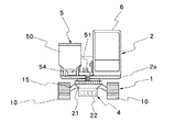
而して、図1乃至図3に本発明の土質改良機械の全体構成を示す。これらの図から明らかなように、下部走行体1と上部旋回体2とから走行車両が構成され、この走行車両には掘削機構として、フロント作業機構3が上部旋回体2に設けられている。また、下部走行体1側には処理ユニット4が設けられ、上部旋回体2側には土質改良材供給手段5が設置されている。さらに、上部旋回体2には運転室6及び機械室7が設置され、機械室7にはエンジン,油圧ポンプ等、機械を駆動するための機器等が収容されており、運転室6はオペレータが搭乗して機械全体の操作が行われる。そして、上部旋回体2は下部走行体1に対して旋回装置8により旋回可能となっている。
【0015】
下部走行体1は左右に設けたクローラ式の走行体10を有し、これら両走行体10はトラックフレーム11の両端に設けたスプロケット12及びアイドラ13と、これらスプロケット12とアイドラ13との間に巻回して設けた履帯14とから構成される。そして、スプロケット12は図示しない油圧モータで駆動されるようになっている。また、左右のトラックフレーム11はセンタフレーム15により連結されており、旋回装置8はこのセンタフレーム15に取り付けられている。ここで、センタフレーム15は旋回装置8が設置されている水平部の両端を下方に曲成して、その両端部にトラックフレーム11が連結されている。従って、センターフレーム15の下部には広いスペースが形成される。
【0016】
フロント作業機構3は掘削手段を構成するものであり、上部旋回体2のフレーム2aに俯仰動作可能に設けたブーム16と、このブーム16の先端に上下方向に回動可能に連結したアーム17と、このアーム17の先端に回動可能に設けたバケット18とから構成される。そして、ブーム16,アーム17及びバケット18はそれぞれ油圧シリンダ16a,17a,18aにより駆動されて、土砂の掘削等の作業が行われる。
【0017】
処理ユニット4は、図4乃至図13に示した構成となっている。処理ユニット4は、図4及び図5から明らかなように、土砂の投入部20と、連続処理槽21と、排出手段22とから構成される。連続処理槽21は、図6に示したように、幅方向の寸法より長さ方向の方が長手となった浅底の容器からなり、上面部と後端部とは開口している。そして、この連続処理槽21は、下部走行体1におけるセンタフレーム15の下部位置に略水平状態に配置されており、その内部には、攪拌機構付きコンベアとして、スクリューコンベア23が4本平行に設けられている。これらスクリューコンベア23は、回転軸23aの外周面に、その軸線に対して所定の角度を持たせた状態で間欠的に羽根23bを装着することにより構成される。これら4本のスクリューコンベア23は、連続処理槽21のほぼ全長に及ぶ長さを有し、相隣接するスクリューコンベア23,23の羽根23b,23bは反対方向に向けて傾斜しており、しかも各羽根23bは、図7に示したように、それと隣接するスクリューコンベア23の回転軸23aに近接する位置にまで延在されている。
【0018】
各スクリューコンベア23の両端は軸受24,24により回転自在に支持されており、それらの回転軸23aの先端は、図8に示したように、連続処理槽21の前端部に設けた駆動部25のハウジング内に延在されている。各回転軸23aの先端には伝達ギア26が連結されており、相隣接する位置の伝達ギア26,26は相互に噛合しており、従って1本の回転軸を回転させると、他の3本の回転軸も回転駆動されるようになる。ただし、相隣接する回転軸23a,23aは反対方向に回転する。1本の回転軸、即ち図8に符号23Daで示した回転軸にはプーリ27が装着され、また駆動部25のハウジング内には油圧モータ28が設けられており、この油圧モータ28の出力軸にはプーリ29が連結して設けられ、これら両プーリ27,29間にはチェーン,ベルト等の伝達部材30が巻回して設けられている。
【0019】
投入部20は、連続処理槽21の前端部の上部に接合するようにして取り付けられる。この投入部20は、上端部が開口した投入口20aとなっており、この投入口20aには簀の子31が設けられており、この簀の子31により岩石やコンクリート等の塊状物や金属等が入り込むのを防止している。しかも、この投入口20aは前方に向けて斜め下方に傾斜しており、従って簀の子31上に残った塊状物等はこの傾斜に沿って落下し易くなっている。また、投入部20の内部には、図9に示したように、土砂を強制的に送り込むための強制送り込み手段32が設けられている。この強制送り込み手段32は回転軸32aに多数の掻き取り爪32bを取り付けたもので、この回転軸32aを図示しない油圧モータ等で回転駆動すると、投入口20aに投入された土砂が強制的に連続処理槽21に向けて送り込まれるようになっている。従って、処理すべき土砂に水分が含まれて粘土状となっていても、投入口20aの部位でブリッジ現象を起こすことなく、円滑に取り込まれるようになる。
【0020】
さらに、排出手段22は連続処理槽21の後端部に連結されている。この排出手段22は連続処理槽21に嵌合される枠状の連結部33と、この連結部33に連設した本体部34とから構成される。本体部34は、前後の壁面と、底壁とからなる排出通路35を有し、この排出通路35には排出コンベア36が設けられている。排出コンベア36は、図10に示したように、排出通路35の両端部にそれぞれ設けた回転軸37a,37bにプーリ38a,38bを取り付け、両プーリ38a,38b間には排土板39を所定のピッチ間隔で多数突設したベルト40が巻回して設けられている。従って、回転軸37a,または37bに油圧モータ41を接続して、この油圧モータ41で回転軸を駆動すると、ベルト40が送られて、連続処理槽21から排出手段22の連結部33内を通り、本体部34の壁面に形成した連通部42から排出通路35に送り込まれた改良土を排土板39で強制的に排出口35aから排出させるようにしている。ここで、排出通路35は走行車両の走行方向と直交する方向に形成されており、排出口35a側は立ち上がる方向に傾斜しており、この排出口35aは、連続処理槽21の位置より高い位置となり、かつ下部走行体10における履帯14の接地面より外側に位置している。そして、ベルト40をこの排出通路35に沿うようにガイドするために、本体部34の壁面にはガイド部材43が設けられる。
【0021】
投入部20は連続処理槽21に固定的に連結され、また排出手段22は、その連結部33が連続処理槽21に嵌合されており、これによって処理ユニット4が構成されるが、排出手段22はロッド状の連結部材44によりセンタフレーム15の下部に固定されている。一方、連続処理槽21は、図11に示したように、センタフレーム15に前後動可能に装着されており、このために連続処理槽21の左右の側壁にはブラケット45が設けられる。図12に示したように、ブラケット45には複数のローラ46が所定の間隔毎に設けられている。また、センタフレーム15の下面には左右一対のガイドレール47が固着して設けられており、ローラ46はこのガイドレール47上を転動するようになっている。さらに、連続処理槽21に固定して設けた投入部20のケーシングとセンタフレーム15との間には油圧シリンダ48が設けられており、この油圧シリンダ48を作動させると、投入部20を連結した連続処理槽21を前後動させることができるようになる。従って、バケット18による通常の土砂掘削時には、投入部20をセンターフレーム15側に移動させることによって、投入部20がバケット18の操作の邪魔になることがなく、また運転室6からの前方視野を広くできるようになっている。一方、投入部20を前方に突出させると、バケット18で掘削した土砂をこの投入部20に円滑に投入できるようになる。
【0022】
連続処理槽21に投入部20から土砂が投入されると、スクリューコンベア23の作動によりこの土砂を攪拌しながら後方に向けて搬送され、この間に塊の状態がほぐされて砂粒の状態になる。そして、搬送途中の位置で、例えばセメント等の土質改良材を供給すると、この土質改良材が土砂に均一に混合されることになる。このために、上部旋回体2側に設けた土質改良材供給手段5は、図13に示したように、土質改良材供給用のタンク50を有し、このタンク50は支持部材51により上部旋回体2のフレーム2aに固定されている。タンク50は円筒形のものであり、その下端部は円錐形状となっている。そして、タンク50の下端部にはフィーダ51が接続されている。
【0023】
フィーダ51は、図14に示したように、円筒状の部材であり、タンク50の下端部から水平方向に曲成されている。この水平方向への延在部にはスクリュー52が設けられており、このスクリュー52は油圧モータ53により回転駆動されるようになっている。これによって、タンク50内の土質改良材を一定量連続的に供給できるようになる。フィーダ51は再び曲成されて、下方に向けられる。そして、フィーダ51は下部走行体1のセンタフレーム15の上面より高い位置にあり、その下方に向けた端部には土質改良材の供給部として可撓筒体54が接続されている。この可撓筒体54は腰のあるゴム筒からなり、その上端の一部を除いて軸線方向に下端部に至る複数箇所の切り込みが形成されて、吹き流しの形状となっている。上部旋回体2が車両の走行方向の前方に向いた状態では、可撓筒体54は連続処理槽21における中央の2本のスクリューコンベア23,23の中間位置に開口するようになっている。また、上部旋回体2を大きく旋回させた時には、可撓筒体54はセンタフレーム15に当接するが、この可撓筒体54は吹き流し状のゴム筒から形成されているから、容易に変形して、センタフレーム15の上に円滑に乗り上げるようになる。
【0024】
以上のように構成される土質改良機械を用いて、所定の地盤における土質改良を行うに当っては、まず地盤のうちの表層部分は良質土である場合には、この表層部分の土を掘削する。この表層土は、ダンプトラック等で現場から搬出し、所定の位置に堆積させておくが、この土質改良機械には掘削手段としてバケット18を有するフロント作業機構3が設けられており、かつ走行手段として接地面積の広い履帯14を備えたものであるから、この表層土の掘削は土質改良機械自体で行うことができる。また、湿地等のような軟弱地では表層部分を含めて土質改良を行わなければならない。表層土を掘削した後の地面は凹凸が生じて走行条件は悪く、また軟弱地も同様に走行条件は悪い。従って、地盤改良を行う現場では、ホイール式の走行手段での走行は極めて困難であるか、または実質的に走行不能なことが多い。本発明による土質改良機械は履帯14を用いた走行体10としているから、このような走行条件の悪い場所でも走行車両を円滑に走行させることができる。
【0025】
そこで、この土質改良機械を用いて地盤改良工事を行うには、図15に示したように、所定の幅Bを有するライン状の掘削領域の土砂を掘削する。また、このようにして掘削した土砂を処理ユニット4を用いて土質改良材を均一に混合して、改良土をこの掘削領域と平行で、しかも土質改良機械の走行領域を隔てた反対側の領域Cに改良土を堆積させる。そして、改良土を領域Cに堆積した後に、この改良土を掘削箇所に埋め戻し、次いで整地及び締め固めを行う。
【0026】
まず表層土を掘削する際には、油圧シリンダ48を縮小させることにより連続処理槽21を引き込むようになし、投入部20を走行車両側に引き込むようにする。この状態で、フロント作業機構3を作動させることによって、表層土の掘削を行うことができる。このようにして掘削した表層土はダンプトラック等で搬出する。作業現場における全ての表層土が取り除かれた後には、地盤そのものは軟弱であり、かつ凹凸が生じている。
【0027】
下部走行体1における左右の走行体10,10を駆動して、走行車両全体を所定の作業位置に配置する。そこで、油圧シリンダ48を伸長させて、連続処理槽21を突出させることによって、投入部20を前方に突出させる。この状態で、フロント作業機構3を作動させることによって、土砂を掘削し、掘削した土砂を投入部20に投入する。投入部20には強制送り込み手段32が設けられているから、投入部20に投入された土砂は円滑に連続処理槽21内に送り込まれる。また、投入口20aには簀の子31が装着されているから、岩石や金属等が分離されて、土砂のみが取り込まれる。連続処理槽21内には4本のスクリューコンベア23が設けられているから、このスクリューコンベア23の回転により投入された土砂は細かく砕かれると共に攪拌されて、砂粒の状態になって後部側に向けて搬送される。そして、フロント作業機構3のバケット18により順次土砂が投入部20に投入され、連続処理槽21内に供給される。
【0028】
連続処理槽21内に供給された土砂は、その搬送途中に土質改良材供給手段5を構成するタンク50からフィーダ51を経て土質改良材が連続処理槽21内に定量ずつ連続的に供給されて、搬送途中の土砂に添加される。従って、スクリューコンベア23の回転により土砂と土質改良材とが攪拌されて、均一に混合されるようになる。そして、土質改良材は、タンク50からフィーダ51及び可撓筒体54を介して直接連続処理槽21に供給できることから、土質改良材が周囲に飛散するおそれはない。このようにして土砂と土質改良材とが均一に混合することにより改良土が生成され、この改良土は連続処理槽21の後端部から排出手段22に向けて押し出されるようになる。
【0029】
而して、連続処理槽21には4本のスクリューコンベア23が設けられており、相隣接するスクリューコンベア同士は反対方向に回転するようになっているから、例えば各スクリューコンベア23を図7のように回転させるようにすることによって、土砂の塊を完全に崩して、それと土質改良材とを均一に混合できる。即ち、中央の2本のスクリューコンベア間では、土砂及び土質改良材は上方から下方に向けた流れを形成するようになし、それぞれ両端のスクリューコンベアとの間では逆に下方から上方に向けた流れを形成することによって、攪拌及び混合が全体にわたって極めて円滑に行われる。また、土質改良材の供給は、この中央の2本のスクリューコンベアの間の位置とするのが全体にわたって均一に攪拌・混合するのに都合が良い。ただし、4本のスクリューコンベア23により連続処理槽21内の全体が均一に攪拌されることから、掘削を行う際に上部旋回体2が旋回して、フィーダ51による土質改良材の供給位置は多少左右にずれても格別混合むら等が生じることはない。
【0030】
以上のようにして生成された改良土が送り出される排出手段22においては、排土板39を設けたベルト40が装着されており、このベルト40を回転させることによって、排出手段22内に送り出された改良土は走行車両の走行と直交する方向に搬送されて、排出用の開口43から排出されて堆積される。ここで、開口43は履帯10の外側の位置において、連続処理槽21より高い位置に形成されているから、履帯10が堆積した改良土を踏んだりすることがなく、また所定の高さにまで改良土を堆積させることができる。しかも、処理ユニット4は下部走行体1側に設けられているから、上部旋回体2を旋回させても、改良土の排出位置は変わらないから、確実に堆積領域Cに堆積することができる。
【0031】
走行車両を走行させながら、フロント作業機構3により所定の深さまで掘削して、連続的に土質改良を行って掘削領域と平行に改良土を堆積させることができる。そして、1つのライン状の掘削及び改良土の堆積からなる作業が終了すると、走行車両を戻しながら、堆積した改良土を掘削箇所に埋め戻す。また、所定の幅を有する1つのライン状の掘削領域の掘削及び埋め戻しによる地盤改良が終了すると、この掘削領域に隣接する掘削領域を同様にラインに掘削して改良土の埋め戻しが行われる。而して、走行車両を自走させながら、バケット18で連続的に掘削して、連続処理槽21による土砂の攪拌及び土質改良材の混合も連続的に行えることから、改良土を効率的に生成でき、また埋め戻しを行うための改良土の堆積箇所は走行車両の側部に位置することから、埋め戻し作業も円滑かつ迅速に行える。
【0032】
以上のように、掘削手段を有する走行車両として、下部走行体1上に旋回装置8を介して上部旋回体2を設置し、この上部旋回体2にフロント作業機構3を設けるという油圧ショベルとしての基本構成を全く損なうことなく、この走行車両に処理ユニット4と土質改良材供給手段5とからなる土質改良機構を設けるようにしている。ここで、土質改良機構の構成としては、前述以外にも以下に示すように種々の形態を採用することは可能である。なお、以下の説明においては、走行車両自体の構成は実質的に変わるところはないので、それを構成する各部材については、同一の符号を付すものとする。
【0033】
まず、前述の実施例においては、処理ユニットは、両履帯間に配置する構成としたが、図16及び図17に示したように、いずれかの履帯の外側に配置することもできる。同図において、60は処理ユニットを示し、この処理ユニット60は、土砂の投入部61と連続処理槽62及び排出手段63とから構成され、連続処理槽62内には、投入された土砂を攪拌しながら、投入部61から排出手段63の位置まで搬送する間に、土質改良材が供給されて、土砂と土質改良材とを均一に混合するための攪拌機構付きコンベアとしてのスクリューコンベア64が装着されている点については、前述した実施の形態と格別の差異はない。
【0034】
この処理ユニット60の形状としては、センタフレーム15による制約がないから、深底に形成できる。ただし、幅方向の寸法をあまり大きくすると、重心位置がずれるので、走行車両全体の安定性が損なわれるおそれがある。このために連続処理槽62の幅を狭くして、スクリューコンベア64は、2本設けるように構成する。ここで、投入部61は運転室6からの視野範囲に入らなければならないことから、履帯14の先端から前方に突出する位置に配置するのが好ましい。そして、投入部61が前方に突出していても、フロント作業機構3による土砂の掘削操作に格別の影響を与えず、また、処理ユニット60により運転室6からの前方の視野が妨げられないから、投入部61を前後動させる必要はなくなる。従って、投入部61を固定的に装着した連続処理槽62をトラックフレーム11に固定し、かつ排出手段63はこの連続処理槽62に固定的に連結することができる。この結果、処理ユニット60の構成を簡略化できる。そして、この構成例では、土質改良材供給手段65を構成するタンク66から連続処理槽62に土質改良材を供給するフィーダ67は連続処理槽62に向けて延在させるようにする。
【0035】
攪拌機構付きコンベアの構成としては、前述したスクリューコンベア23,64以外にも、例えば図18に示したように、回転軸23a′に螺旋状に連続した羽根23b′を設けたスクリューコンベア23′として構成することもできる。要は、連続処理槽内において、その前端部側から後端部側に搬送する間に連続的に全体にわたって均一に攪拌・混合されるようになっておれば良く、攪拌機構付きコンベアの構成及び配置する数は任意である。
【0036】
次に、連続処理槽においては、土質改良材は、その幅方向の中央部に供給すると、土砂の全体にわたって均一に混合する上で有利である。ただし、処理ユニットは下部走行体1側に、また土質改良材供給手段は上部旋回体2側に配置されている。従って、土砂を掘削する際には、フロント作業機構3を掘削箇所に向けるために、上部旋回体2を旋回させるが、この時には土質改良材供給手段のフィーダから連続処理槽への供給位置がずれることになる。そこで、上部旋回体2の旋回位置の如何に拘らず、常に一定の位置から土質改良材を供給するには、上部旋回体2の旋回中心の位置に土質改良材の供給部を配置すれば良い。ただし、上部旋回体2の旋回中心には、上部旋回体2側と下部走行体1側との間で作動油の流通を確保するために、センタジョイント(図示せず)が設けられている。従って、このセンタジョイントの部位を貫通させるか、または少なくともセンタジョイントの下部の位置に開口させるように構成すれば、常に一定の位置から土質改良材の供給を行える。
【0037】
センタジョイントの構成を変えずに、また上部旋回体2のフレーム2a等の構造部材に土質改良材の供給経路を形成するための透孔等を設けずに、上部旋回体2の旋回位置に拘らず常に一定の位置で連続処理槽に土質改良材を供給できるようにするには、図19及び図20に示した構成とすれば良い。
【0038】
これらの図から明らかなように、連続処理槽70には、その軸線方向の所定の位置に取付板71を装着して、この取付板71にバッファタンク72を固定的に取り付ける。ここで、バッファタンク72は、所定の土質改良材を収容できる容量を有する容器からなり、その上端部は開口72aとなっている。そして、このバッファタンク72の下端部には、土質改良材を連続処理槽70に定量的、かつ連続的に供給する定量送り手段として、スクリューを内蔵した第2のフィーダ73が接続されており、この第2のフィーダ73の土質改良材の供給部は連続処理槽70における前後方向における所定の位置で、幅方向においては中央の位置に開口するように構成している。従って、このバッファタンク72に所定量の土質改良材を収容させておけば、上部旋回体2が旋回しても、土質改良材は連続処理槽70の所定の位置に供給できることになる。
【0039】
ただし、大容量のバッファタンク72を用いると、上部旋回体2の旋回時の邪魔になり、また運転室6からの視野が制限される。従って、バッファタンク72は小型のものとする。そこで、上部旋回体2には、バッファタンク72に土質改良材を供給するために、タンク74とフィーダ75とからなる土質改良材供給手段76を設けて、フィーダ75に吹き流し形状の可撓筒体77を接続し、この供給部77をバッファタンク72に接続する。
【0040】
ここで、図15に示したように、掘削領域の幅Bにおいてフロント作業機構3で土砂の掘削を行うに当っては、上部旋回体2が所定角度往復旋回することになり、この時には可撓筒体77も動くが、この掘削時の上部旋回体2の動きの範囲では、可撓筒体77がバッファタンク72の上端の開口72aの内部に位置するように、例えば楕円錐形状の容器で構成する。これによって、タンク74からバッファタンク72に連続的に土質改良材を供給できる。ただし、フィーダ75で土質改良材を間欠的に供給するように構成すれば、上部旋回体2の旋回によって、フィーダ75がバッファタンク72の上部位置からずれた時に、土壌改良材の供給を停止すれば、土質改良材が外部に飛散するおそれはない。
【0041】
さらに、排出手段としては、土砂と土質改良土とを混合した改良土を履帯14の接地面の延長線を外した位置において、所定の高さから排出させるように、揚土機能を持たせる構成とするが、図21に示したように、排出手段80の本体部81の左右両側に立ち上がる方向に傾斜する排出通路82を設けることもできる。この場合には、両側が排出口82a,82bとなる。そして、多数の排土板83を取り付けたベルト84を、これら両排出口82a,82bの近傍に設けた回転軸85a,85bに装着したプーリ86a,86bに巻回して設けて、図示しない油圧モータでベルト84を送るように構成する。そして、ベルト84を排出通路82に沿うようにガイドするために、本体部81にはガイド部材87を設けるようにする。このように構成すれば、ベルト84の送り方向によっては、連続処理槽から送り込まれた改良土を排出口82aまたは82bから排出できるようになる。
【0042】
さらに、改良土の排出時にこの改良土を所定の高さまで持ち上げる揚土手段としては、以上のものの他、図22に示したようにコンベア手段90を用いることができる。このコンベア手段90は、左右一対からなるアーム91間に連結した一対の回転軸92a,92b間にコンベアベルト93を巻回させたものであり、アーム91を所定角度上向きに傾斜させることによって、改良土の揚土を行うことができる。而して、このコンベア手段90を設ける場合には、排出手段94の排出通路95としては、図示のように、水平なものとすることもできるが、排出通路が所定角度立ち上がるようにした排出手段22,80に接続するように構成しても良い。
【0043】
改良土を埋め戻した後には、整地を行うが、この整地はバケット18でも行えるが、図23に示したように、ブレード100を用いて行うことができる。ブレード100は、ブレード本体101と、このブレード本体101を上下方向に回動させるために、レバー102及びブレード駆動用の油圧シリンダ103とを有し、レバー102はブレード本体101に固定的に取り付けられており、その他端は処理ユニット104の先端部にピン105で枢着されている。また、油圧シリンダ103の両端は、ブレード本体101と処理ユニット104とにそれぞれピン106a,106bを用いて枢着されている。従って、油圧シリンダ103を伸長状態にすると、図23に仮想線で示したように、ブレード本体101は上方に回動して傾斜状態となり、走行車両の走行時に地面や地面上の突出物に当ることがなく、円滑な走行が可能となる。一方、油圧シリンダ103を縮小すると、ブレード本体101は下方に向けて回動して、その下端部が地面にほぼ接触し、かつほぼ鉛直状態になる。これによって、埋め戻した箇所に凹凸がある場合でも、走行車両の走行により整地を行うことができる。
【0044】
さらに、図24に示したように、処理ユニット110を構成する排出手段111を走行車両の進行方向の後方位置に向けて改良土を排出するように構成することもできる。そして、ブレード112は走行車両の後方位置に設ける。また、ブレード112のブレード本体113は下部走行体1のセンタフレーム15から後方に向けて突出する取付板114にピン115で枢着すると共に、その中間部に油圧シリンダ116を連結する構成としている。
【0045】
ここで、排出手段111は、図25に示したように、油圧モータ等で駆動される回転軸117に排土板118を例えば90°毎に連結して設け、この回転軸117を回転駆動することによって、排土板118を回転させることにより、この排出手段111側に送り込まれた改良土を排出口111aから排出させることができる。また、ブレード112を構成するブレード本体113は、油圧シリンダ116によりブレード本体113をほぼ鉛直状態にすると、同図に実線で示したように、排出口111aの後方部位を覆うようになり、かつその下端部は地面とほぼ接触する状態になる。また、仮想線で示した状態に傾斜させると、このブレード本体113の下端部は地面から離間すると共に排出手段111の排出口111aから離間する方向に変位する。
【0046】
従って、ブレード本体113を傾斜させることによって、排出口111aからの改良土の排出を可能とし、ブレード本体113をほぼ鉛直状態にして、走行車両を後進させると、排出口111aから排出された改良土は後方に押されて盛り上げるようにすることができる。このように構成すれば、改良土を一時堆積させることなく、掘削を行って土質改良材と混合した後に、直ちに埋め戻すことができるようになる。
【0047】
【発明の効果】
以上説明したように、本発明は、掘削機構で掘削した土砂が投入されて、土質改良材と混合・攪拌することにより改良土を連続的に生成して、この改良土を連続的に排出するようになし、この改良土を生成するために、水平方向に所定の長さを有する連続処理槽を、土砂の投入部及び改良土の排出手段と共に、履帯を有する下部走行体側に設け、また掘削機構が装着される上部旋回体側に土質改良材供給手段を設ける構成としたので、土砂と土質改良材とを混合するに当って、土質改良材が周囲に飛散して周囲環境に悪影響を与える等の不都合を生じることがなく、しかも掘削手段により所望の深さまで掘削して連続的かつ安定的に改良土を生成できるので、地盤を正確かつ効率的に改良できる等の効果を奏する。
【図面の簡単な説明】
【図1】本発明の実施の一形態を示す掘削手段付き土質改良機械の側面図である。
【図2】フロント作業機構を省略して示す図1の正面図である。
【図3】フロント作業機構を省略して示す図1の平面図である。
【図4】処理ユニットの側面図である。
【図5】図4の平面図である。
【図6】処理ユニットの分解斜視図である。
【図7】連続処理槽の横断面図である。
【図8】スクリューコンベアの駆動機構の構成説明図である。
【図9】投入部の断面図である。
【図10】排出手段の正面図である。
【図11】連続処理槽の前後動駆動機構を示す構成説明図である。
【図12】図11のX−X断面図である。
【図13】土質改良材供給手段の構成を示す外観図である。
【図14】フィーダの断面図である。
【図15】土質改良機械による地盤改良の手順を示す説明図である。
【図16】連続処理槽の他の構成例を装着した土質改良機械の正面図である。
【図17】図16の平面図である。
【図18】攪拌機構付きコンベアの他の構成例を示す要部正面図である。
【図19】土質改良材供給部の他の構成例を示す平面図である。
【図20】図19のY−Y位置での断面図である。
【図21】排出手段の他の構成例を示す断面図である。
【図22】排出手段から排出される改良土を揚土する他の機構の構成説明図である。
【図23】下部走行体に装着されるブレードの構成説明図である。
【図24】改良土を走行車両の後方位置に排出するように構成した土質改良機械の側面図である。
【図25】図24の土質改良機械における改良土の排出手段と、排出された改良土を揚土する機構とを示す断面図である。
【符号の説明】
1 下部走行体 2 上部旋回体
3 フロント作業機構 4,60 処理ユニット
5,65,76 土質改良材供給手段 10 走行体
14 履帯 15 センタフレーム
16 ブーム 17 アーム
18 バケット 20,61 投入部
21,62,70 連続処理槽 22,63,80,95 排出手段
23,64 スクリューコンベア 25 駆動部
31 簀の子 32 強制送り込み手段
34,81 本体部 35,82 排出通路
36 排出コンベア 39 排土板
40 ベルト 50,65 タンク
51,67,75 フィーダ 52 スクリュー
54,77 可撓筒体 72 バッファタンク
90 コンベア手段 94 コンベアベルト
100,112 ブレード 101,113 ブレード[0001]
BACKGROUND OF THE INVENTION
The present invention relates to a soil improvement machine equipped with excavation means used for excavating earth and sand in a civil engineering site or a construction site and refilling the excavated soil.
[0002]
[Prior art]
As a construction method for improving the soft ground to make it a solid ground, there has been conventionally known a method in which a soil improving material such as cement is mixed with the soil constituting the ground and solidified. . In this method, the earth and sand that make up the ground are dug up to a predetermined depth, cement and other soil improvement materials that solidify the soil are uniformly mixed, and then backfilled and leveled, and finally tightened. It is common to harden. This soil improvement method requires means for excavating earth and sand, means for supplying soil improvement material, means for uniformly mixing the excavated earth and soil improvement material, and means for leveling and compacting. .
[0003]
Here, in the soil improvement method, at least a means for excavating the earth and sand is required. As the excavating means, a hydraulic excavator is generally used. Here, the traveling means in the hydraulic excavator include a crawler type using a crawler belt and a wheel type having wheels, but the ground on the work site is generally soft and has unevenness. Since it is also leveling, it is necessary to use a crawler type with a crawler track as a traveling means from the viewpoint of poor traveling conditions, the need to ensure the stability of the vehicle body due to excavation resistance, etc. .
[0004]
Next, the soil improvement material is supplied and mixed with the earth and sand to produce the improved soil. The method of generating this improved soil is roughly divided into a method of stirring and mixing using a mixing device, 2. Description of the Related Art Conventionally, a method of mixing earth and sand with a soil quality improving material by dispersing the soil quality improving material on the ground and stirring it while digging up the earth and sand has been used.
[0005]
As a mixing device, at least, a mixing tank equipped with a stirring means and a soil quality improving material supply means are provided. And earth and sand are thrown into the mixing tank. Since excavation of the earth and sand is performed by a hydraulic excavator, the earth and sand can be directly fed from the hydraulic excavator to the mixing device. However, since the positional relationship between the excavation position of the hydraulic excavator and the arrangement position of the mixing device always changes, the sediment excavated by the hydraulic excavator is accumulated at a predetermined site, and the accumulated sediment is taken in. Is common. Here, as this kind of mixing apparatus, for example, the one shown in Japanese Patent Publication No. 1-449538 is known. This mixing apparatus is configured as a self-propelled mixing apparatus including a wheel-type traveling means, including a sediment supply mechanism including a bucket for supplying volume sediment, a mixing tank and a soil quality improvement material supply unit. Moreover, the earth and sand supply mechanism can be rotated in a horizontal direction by a limited angle on the vehicle body. Furthermore, in this mixing tank, after adding a fixed amount of soil and a fixed amount of soil improvement material, improved soil is generated by stirring and mixing with a stirring means, and discharged to a predetermined position. Processing is performed batchwise.
[0006]
On the other hand, in the system in which the soil quality improving material is sprayed on the ground and mixed with the earth and sand, the soil quality improving material is sprayed, and then the earth and sand are dug up and stirred and mixed. In this case, the agitation and mixing of the earth and sand and the soil improvement material can be carried out using a drilling mechanism equipped with a bucket in a hydraulic excavator, but the earth and sand and the soil quality improvement material are uniformly agitated and mixed over a wide area. Is difficult and requires a high level of skill. In view of this, a method for uniformly stirring and mixing the soil quality improving material sprayed using the excavating and mixing stirring means is disclosed in, for example, Japanese Utility Model Laid-Open No. 56-733. This known excavation mixing agitation means includes a rotor in which a large number of cutters are radially connected to a rotating shaft, and can be attached to the tip of an arm provided as a front attachment in a front working mechanism of a hydraulic excavator. It has become. Then, while the hydraulic excavator is running, the boom and the arm are operated to press the cutter in the rotor against the ground, and the rotary shaft is rotated to rotate the cutter so that the soil is dug up. Can be mixed with earth and sand.
[0007]
[Problems to be solved by the invention]
By the way, in the system which produces | generates improved soil using a self-propelled mixing apparatus, it is necessary to excavate earth once using a hydraulic shovel. In this self-propelled mixing device, a sediment supply mechanism including a bucket is provided, but the sediment cannot be directly excavated by this sediment supply mechanism. The reason for this is that it is equipped with wheel-type traveling means that are not suitable for traveling on soft ground or rough terrain such as a work site, and the horizontal rotation angle of the earth and sand supply mechanism is also limited. This is because excavation at an arbitrary position cannot be performed and the stability of the vehicle with respect to excavation resistance cannot be ensured. Therefore, excavated earth and sand must be deposited at a position where the mixing device can travel using a hydraulic excavator or the like, which increases the number of work steps. Moreover, since the soil quality improvement processing of the earth and sand by a mixing tank is performed by a batch type, dissatisfaction remains in terms of processing capacity.
[0008]
On the other hand, in the method using the excavation mixing and stirring means, there is no need for excavation and sedimentation of sediment, and since it is a continuous treatment, the treatment capacity is high, but since the soil improvement material such as cement is sprayed, this soil There is a problem that the improved material is scattered to adversely affect the surrounding environment and is not suitable for work in densely populated areas such as generation of noise when the rotor is driven. In addition, the excavation depth depends on the length of the cutter, the length of the cutter is limited, and the length of the cutter currently in use is about 1 m at the longest. There is also a problem that it is not suitable for ground improvement.
[0009]
The present invention has been made in view of the above points, and an object thereof is to make it possible to accurately and efficiently improve the ground up to a desired depth without adversely affecting the surrounding environment. It is in.
[0010]
[Means for Solving the Problems]
In order to achieve the above-described object, the present invention provides a soil improvement machine that performs soil improvement by mixing and agitating a soil improvement material in the earth and sand excavated by an earth and sand excavation mechanism having a bucket. A traveling vehicle having a lower traveling body and an upper revolving body installed so as to be able to swivel with respect to the lower traveling body, wherein the upper revolving body is supplied with soil excavation mechanism and soil quality improvement material. Improvement material supply means is provided, and the lower traveling body is provided with a continuous processing tank having a predetermined length in the horizontal direction and having one or a plurality of conveyors with a stirring mechanism installed therein. An input portion into which earth and sand are introduced from the bucket of the excavation mechanism on one end side of the treatment tank, and a means for discharging the improved soil obtained by stirring and mixing the introduced earth and soil quality improving material on the other end side. Provided Ri, the soil improvement agent supply means, The soil improvement material supply tank and a feeder for supplying the soil improvement material from the soil improvement material supply tank to the continuous treatment tank. It is characterized in that it is configured to be supplied to the continuous processing tank from a position between the input section and the discharge means.
[0011]
Subsequent treatment tanks constituting the soil quality improvement mechanism, an input part for introducing earth and sand from a bucket, and a discharge means for improving soil attached to the other end of the continuous treatment tank are provided at the lower side. Provided on the traveling body side. The soil excavation mechanism and the soil improvement material supply means for supplying the soil improvement material are provided in the upper rotating body, and the soil improvement material supply means is located between the input section and the discharge means with respect to the continuous treatment tank. Supplied from. The continuous treatment tank is disposed between the pair of left and right crawler belts in the lower traveling body or outside one of the crawler belts. The discharging means is fixed to the center frame of the lower traveling body, and the continuous processing tank can be moved in the front-rear direction of the traveling vehicle. The conveyor with the stirring mechanism provided in the continuous processing tank is a rotating shaft. It is possible to adopt a configuration in which the blades are attached continuously or intermittently to the outer peripheral surface of the outer peripheral surface with a predetermined angle in the axial direction.
[0012]
The soil improvement material supply means may include a soil improvement material supply tank and a feeder that supplies the soil improvement material from the soil improvement material supply tank to the continuous treatment tank. In addition, a buffer tank is attached to the continuous processing tank so that the soil quality improving material is supplied to the buffer tank from the feeder supply port via the flexible cylinder. It is possible to connect to the buffer tank by a predetermined rotation angle of the body, and if this buffer tank is provided with a quantitative feed means for quantitatively supplying the soil improvement material to the continuous treatment tank, the upper revolving body can be swiveled. Nevertheless, the soil improvement material can always be supplied to a certain position.
[0013]
DETAILED DESCRIPTION OF THE INVENTION
Hereinafter, embodiments of the present invention will be described with reference to the drawings. Here, the excavation mechanism provided in the soil improvement machine of the present invention has the same configuration as the excavation mechanism in the hydraulic excavator. Therefore, the basic configuration of the soil improvement machine is a conventionally known hydraulic excavator, and this hydraulic excavator. The soil improvement mechanism is mounted without impairing the function of the hydraulic excavator and without making any special modification to the configuration of the hydraulic excavator.
[0014]
Thus, FIGS. 1 to 3 show the overall structure of the soil improvement machine of the present invention. As is clear from these drawings, a traveling vehicle is constituted by the
[0015]
The
[0016]
The
[0017]
The
[0018]
Both ends of each
[0019]
The charging
[0020]
Further, the discharging
[0021]
The
[0022]
When the earth and sand are thrown into the
[0023]
As shown in FIG. 14, the
[0024]
Using the soil improvement machine configured as described above, in order to improve the soil quality in a given ground, first, if the surface layer portion of the ground is of high quality soil, the soil in this surface layer portion is excavated. To do. This surface soil is carried out from the site by a dump truck or the like and is deposited at a predetermined position. This soil improvement machine is provided with a
[0025]
Therefore, in order to perform ground improvement work using this soil improvement machine, as shown in FIG. 15, the soil in the line-shaped excavation area having a predetermined width B is excavated. Further, the soil excavated in this way is uniformly mixed with the soil improvement material using the
[0026]
First, when excavating the surface soil, the
[0027]
The left and right traveling
[0028]
The soil and sand supplied into the
[0029]
Thus, the
[0030]
In the discharging means 22 to which the improved soil generated as described above is sent out, a
[0031]
While the traveling vehicle is traveling, the
[0032]
As described above, as a traveling vehicle having excavating means, the
[0033]
First, in the above-described embodiment, the processing unit is arranged between the two crawler belts. However, as shown in FIGS. 16 and 17, the processing unit may be arranged outside one of the crawler belts. In the figure,
[0034]
Since the shape of the
[0035]
As a configuration of the conveyor with a stirring mechanism, in addition to the
[0036]
Next, in the continuous treatment tank, when the soil quality improving material is supplied to the central portion in the width direction, it is advantageous in uniformly mixing the entire soil. However, the processing unit is disposed on the
[0037]
Without changing the configuration of the center joint, and without providing a through hole or the like for forming a supply path for the soil improvement material in the structural member such as the
[0038]
As is apparent from these drawings, a mounting
[0039]
However, if a large-
[0040]
Here, as shown in FIG. 15, when excavating the earth and sand with the
[0041]
Further, the discharging means is configured to have a function of unloading so that the improved soil obtained by mixing the soil and the soil improved soil is discharged from a predetermined height at a position where the extended line of the contact surface of the
[0042]
Further, as the earthing means for lifting the improved soil to a predetermined height when the improved soil is discharged, a conveyor means 90 can be used as shown in FIG. This conveyor means 90 is obtained by winding a
[0043]
After the improved soil is backfilled, leveling is performed. This leveling can also be performed by the
[0044]
Furthermore, as shown in FIG. 24, the discharging means 111 constituting the
[0045]
Here, as shown in FIG. 25, the discharging means 111 is provided with a
[0046]
Therefore, by tilting the
[0047]
【The invention's effect】
As described above, according to the present invention, the soil excavated by the excavation mechanism is input, and the improved soil is continuously generated by mixing and stirring with the soil quality improving material, and the improved soil is continuously discharged. No way, In order to generate this improved soil, a continuous processing tank having a predetermined length in the horizontal direction is provided on the lower traveling body side having the crawler belt together with the earth and sand charging unit and the improved soil discharging means, and an excavation mechanism is mounted. Provide soil improvement material supply means on the upper revolving structure side Since it is configured, when mixing the earth and sand and the soil conditioner, the soil conditioner will not scatter to the surroundings and adversely affect the surrounding environment. Drilling and continuous And stable Since the improved soil can be generated, it is possible to improve the ground accurately and efficiently.
[Brief description of the drawings]
FIG. 1 is a side view of a soil improvement machine with excavation means showing an embodiment of the present invention.
FIG. 2 is a front view of FIG. 1 with the front working mechanism omitted.
3 is a plan view of FIG. 1 with the front working mechanism omitted.
FIG. 4 is a side view of a processing unit.
FIG. 5 is a plan view of FIG. 4;
FIG. 6 is an exploded perspective view of a processing unit.
FIG. 7 is a cross-sectional view of a continuous processing tank.
FIG. 8 is a diagram illustrating the configuration of a screw conveyor drive mechanism.
FIG. 9 is a cross-sectional view of a charging portion.
FIG. 10 is a front view of the discharging means.
FIG. 11 is a configuration explanatory view showing a longitudinal movement drive mechanism of a continuous processing tank.
12 is a sectional view taken along line XX in FIG.
FIG. 13 is an external view showing a configuration of a soil improvement material supply means.
FIG. 14 is a cross-sectional view of a feeder.
FIG. 15 is an explanatory diagram showing the ground improvement procedure by the soil improvement machine.
FIG. 16 is a front view of a soil improvement machine equipped with another configuration example of a continuous treatment tank.
FIG. 17 is a plan view of FIG. 16;
FIG. 18 is a main part front view showing another configuration example of the conveyor with a stirring mechanism.
FIG. 19 is a plan view showing another configuration example of the soil improvement material supply unit.
20 is a cross-sectional view taken along the YY position in FIG.
FIG. 21 is a cross-sectional view showing another configuration example of the discharging means.
FIG. 22 is a diagram illustrating the configuration of another mechanism for unloading the improved soil discharged from the discharging means.
FIG. 23 is a diagram illustrating the configuration of a blade mounted on the lower traveling body.
FIG. 24 is a side view of a soil quality improvement machine configured to discharge the improved soil to a rear position of a traveling vehicle.
25 is a cross-sectional view showing an improved soil discharging means and a mechanism for unloading the discharged improved soil in the soil quality improvement machine of FIG. 24. FIG.
[Explanation of symbols]
1 Lower traveling
3
5,65,76 Soil improvement material supply means 10 traveling body
14
16
18
21, 62, 70
23,64
31
34,81
36
40
51, 67, 75
54,77
90 Conveyor means 94 Conveyor belt
100, 112
Claims (13)
左右一対の履帯を有する下部走行体と、この下部走行体に対して旋回可能に設置した上部旋回体とを有する走行車両を備え、
前記上部旋回体には、前記土砂の掘削機構と、土質改良材を供給する土質改良材供給手段とが設けられ、
また前記下部走行体には、水平方向に所定の長さを有し、内部に1または複数の攪拌機構付きコンベアを装着した連続処理槽が設けられ、この連続処理槽の一端側に、前記掘削機構のバケットから土砂が投入される投入部と、他端側に、投入土砂と土質改良材とを撹拌・混合することにより得られる改良土の排出手段とが設けられており、
前記土質改良材供給手段は、土質改良材供給タンクと、この土質改良材供給タンクから土質改良材を前記連続処理槽に供給するフィーダとからなり、このフィーダはこれら投入部と排出手段との間の位置から前記連続処理槽に供給される
構成としたことを特徴とする土質改良機械。In a soil improvement machine that improves soil quality by mixing and stirring soil improvement material into the soil excavated by the soil excavation mechanism with a bucket,
A traveling vehicle having a lower traveling body having a pair of left and right crawler belts and an upper revolving body installed so as to be capable of turning with respect to the lower traveling body;
The upper swivel body is provided with the soil excavation mechanism and a soil improvement material supply means for supplying a soil improvement material,
Further, the lower traveling body is provided with a continuous processing tank having a predetermined length in the horizontal direction and having one or more conveyors with a stirring mechanism mounted therein, and the excavation is provided at one end of the continuous processing tank. The input part where the earth and sand is input from the bucket of the mechanism, and the other end side are provided with a means for discharging the improved earth obtained by stirring and mixing the input earth and soil improvement material,
The soil improvement material supply means comprises a soil improvement material supply tank and a feeder that supplies the soil improvement material from the soil improvement material supply tank to the continuous treatment tank, and the feeder is provided between the input section and the discharge means. A soil improvement machine characterized in that it is configured to be supplied to the continuous treatment tank from the position.
Priority Applications (5)
| Application Number | Priority Date | Filing Date | Title |
|---|---|---|---|
| JP14607397A JP3709654B2 (en) | 1997-05-21 | 1997-05-21 | Soil improvement machine with excavation means |
| DE69832246T DE69832246T2 (en) | 1997-05-21 | 1998-05-20 | SOIL ENHANCEMENT MACHINE WITH GRAVING DEVICES |
| EP98921728A EP0915205B1 (en) | 1997-05-21 | 1998-05-20 | Soil improving machine with excavating means |
| PCT/JP1998/002208 WO1998053148A1 (en) | 1997-05-21 | 1998-05-20 | Soil improving machine with excavating means |
| US09/147,565 US6171030B1 (en) | 1997-05-21 | 1998-05-20 | Soil improving machine with excavating means |
Applications Claiming Priority (1)
| Application Number | Priority Date | Filing Date | Title |
|---|---|---|---|
| JP14607397A JP3709654B2 (en) | 1997-05-21 | 1997-05-21 | Soil improvement machine with excavation means |
Publications (2)
| Publication Number | Publication Date |
|---|---|
| JPH10317426A JPH10317426A (en) | 1998-12-02 |
| JP3709654B2 true JP3709654B2 (en) | 2005-10-26 |
Family
ID=15399496
Family Applications (1)
| Application Number | Title | Priority Date | Filing Date |
|---|---|---|---|
| JP14607397A Expired - Fee Related JP3709654B2 (en) | 1997-05-21 | 1997-05-21 | Soil improvement machine with excavation means |
Country Status (5)
| Country | Link |
|---|---|
| US (1) | US6171030B1 (en) |
| EP (1) | EP0915205B1 (en) |
| JP (1) | JP3709654B2 (en) |
| DE (1) | DE69832246T2 (en) |
| WO (1) | WO1998053148A1 (en) |
Families Citing this family (29)
| Publication number | Priority date | Publication date | Assignee | Title |
|---|---|---|---|---|
| JP3387829B2 (en) | 1998-07-24 | 2003-03-17 | 日立建機株式会社 | Self-propelled soil improvement machine |
| JP2000355954A (en) | 1999-06-15 | 2000-12-26 | Komatsu Ltd | Self-propelled soil improvement machine |
| JP2001115486A (en) * | 1999-10-21 | 2001-04-24 | Komatsu Ltd | Material supplying machine for fluidization-treated soil |
| JP3772306B2 (en) | 2002-07-30 | 2006-05-10 | 株式会社小松製作所 | Soil improvement device |
| US7069677B2 (en) * | 2003-10-07 | 2006-07-04 | Cheng-Feng Chang | Method for producing a ready-mix soil material |
| WO2006033399A1 (en) * | 2004-09-24 | 2006-03-30 | Komatsu Ltd. | Slewing controller, slewing control method, and construction machine |
| WO2009001587A1 (en) * | 2007-06-26 | 2008-12-31 | Hitachi Construction Machinery Co., Ltd. | Self-propelled construction machine |
| GB2478150A (en) * | 2010-02-26 | 2011-08-31 | Yorkshire Water Services Ltd | A material recycling apparatus for processing trench arisings |
| JP5228000B2 (en) * | 2010-05-26 | 2013-07-03 | 日立建機株式会社 | Hybrid construction machine |
| JP2012082644A (en) * | 2010-10-14 | 2012-04-26 | Hitachi Constr Mach Co Ltd | Construction machine |
| US10016795B2 (en) | 2012-12-13 | 2018-07-10 | Exxonmobil Research And Engineering Company | Remediation of contaminated particulate materials |
| AU2014241581B2 (en) * | 2013-03-25 | 2018-10-18 | Joy Global Underground Mining Llc | Mobile sizer with integrated load bucket |
| CN103643021B (en) * | 2013-09-05 | 2015-08-19 | 格林精密部件(苏州)有限公司 | For carrying the inclined ramp structure of motor shaft |
| CN108568450A (en) * | 2017-03-12 | 2018-09-25 | 上海康恒环境股份有限公司 | A kind of automatic control system of self-propelled soil remediation equipment |
| US10835939B2 (en) * | 2017-05-30 | 2020-11-17 | Chevron U.S.A. Inc. | Systems and methods for thermal destruction of undesired substances by smoldering combustion |
| CN108396805A (en) * | 2018-03-14 | 2018-08-14 | 彭红星 | A kind of underground storage object for building fills device automatically |
| US10786905B1 (en) * | 2018-04-16 | 2020-09-29 | AGI Engineering, Inc. | Tank excavator |
| KR102687696B1 (en) * | 2018-10-03 | 2024-07-22 | 스미도모쥬기가이고교 가부시키가이샤 | shovel |
| CN109604328B (en) * | 2019-01-16 | 2020-12-25 | 安徽工程大学 | Device for repairing heavy metal contaminated soil and repairing method thereof |
| CN109565988B (en) * | 2019-01-31 | 2024-05-10 | 中国盐业总公司盐业地质勘查大队 | Saline-alkali soil treatment system and treatment method thereof |
| CN112663595B (en) * | 2020-12-03 | 2022-05-20 | 上海市基础工程集团有限公司 | Adjusting and fixing device for first root locking section steel of underground continuous steel wall |
| KR102345901B1 (en) * | 2021-06-04 | 2022-01-03 | 주식회사 동해종합기술공사 | Self-driving integrated functional soil mixer |
| KR102355019B1 (en) * | 2021-06-04 | 2022-02-09 | 주식회사 동해종합기술공사 | A method of soil purification using a self-contained integrated functional soil mixing system |
| CN113290039B (en) * | 2021-06-08 | 2023-06-27 | 河南工程学院 | Soil conditioner application device and method |
| CN115156269A (en) * | 2022-07-14 | 2022-10-11 | 中国矿业大学 | Soil remediation equipment for environmental improvement |
| CN115569977A (en) * | 2022-10-01 | 2023-01-06 | 张红瑞 | A chemical spraying treatment device for soil remediation |
| CN118180133B (en) * | 2024-05-13 | 2024-07-16 | 烟台市森林资源监测保护服务中心(烟台沿海防护林省级自然保护区管理服务中心、烟台市林业科学研究所) | Soil fully and uniformly repairing equipment for forestry |
| CN118390491B (en) * | 2024-06-04 | 2025-03-07 | 中冶武勘工程技术有限公司 | Ecological environment treatment mechanism for geological disasters |
| CN118895812A (en) * | 2024-08-15 | 2024-11-05 | 中国科学院西北生态环境资源研究院 | A self-adjusting support system and self-adjusting method for engineering structures in permafrost areas |
Family Cites Families (16)
| Publication number | Priority date | Publication date | Assignee | Title |
|---|---|---|---|---|
| JPS56733A (en) | 1979-06-15 | 1981-01-07 | Mitsubishi Electric Corp | Automatic gain control circuit for plural channels |
| JPS6265727A (en) * | 1985-09-17 | 1987-03-25 | Koyo Kikai Sangyo Kk | Mixing device for improving foundation |
| JPS6449538A (en) | 1987-08-20 | 1989-02-27 | Sanyo Electric Co | Processing method for pulse rate at pulsimeter |
| US4913586A (en) * | 1988-08-15 | 1990-04-03 | Analytical Liquid Waste Systems, Inc. | Mixture for detoxification of contaminated soil |
| JPH03209A (en) * | 1989-05-29 | 1991-01-07 | Sagami Serbo Kk | Kneader |
| US5242246A (en) * | 1992-02-18 | 1993-09-07 | Terranalysis Corporation | Surface remediator |
| JPH07113214B2 (en) * | 1992-04-01 | 1995-12-06 | トーメン建機株式会社 | Excavation device for underground wall and construction method using the device |
| WO1994025191A1 (en) * | 1993-05-03 | 1994-11-10 | Bruso Bruce L | Method and apparatus for in situ soil remediation |
| US6017169A (en) * | 1993-08-30 | 2000-01-25 | Itex, Division Of Irm, L.P. | Remediation of earthen material |
| US5490741A (en) * | 1993-10-21 | 1996-02-13 | Red Rose Environmental, Inc. | Metered blending equipment for soils, sludges and liquid/solid mixtures |
| US5566627A (en) * | 1994-01-18 | 1996-10-22 | Pryor; Alan E. | Method and apparatus for ozone treatment of soil to kill living organisms |
| JPH0841928A (en) * | 1994-07-27 | 1996-02-13 | Komatsu Esuto:Kk | Civil engineering construction machine |
| JP3357495B2 (en) * | 1995-01-31 | 2002-12-16 | 株式会社小松製作所 | Self-propelled reclaimed soil vehicle |
| US5558471A (en) * | 1995-03-23 | 1996-09-24 | Payne; Gary L. | Device for injecting chemicals into the soil |
| US5837325A (en) * | 1995-07-14 | 1998-11-17 | Heacock; Gary E. | Method and apparatus for regulating neutralization of contaminated soil |
| US5639182A (en) * | 1995-10-12 | 1997-06-17 | Paris; James L. | In situ treatment of soil |
-
1997
- 1997-05-21 JP JP14607397A patent/JP3709654B2/en not_active Expired - Fee Related
-
1998
- 1998-05-20 WO PCT/JP1998/002208 patent/WO1998053148A1/en active IP Right Grant
- 1998-05-20 EP EP98921728A patent/EP0915205B1/en not_active Expired - Lifetime
- 1998-05-20 US US09/147,565 patent/US6171030B1/en not_active Expired - Fee Related
- 1998-05-20 DE DE69832246T patent/DE69832246T2/en not_active Expired - Fee Related
Also Published As
| Publication number | Publication date |
|---|---|
| JPH10317426A (en) | 1998-12-02 |
| US6171030B1 (en) | 2001-01-09 |
| DE69832246D1 (en) | 2005-12-15 |
| EP0915205A1 (en) | 1999-05-12 |
| DE69832246T2 (en) | 2006-07-13 |
| WO1998053148A1 (en) | 1998-11-26 |
| EP0915205B1 (en) | 2005-11-09 |
| EP0915205A4 (en) | 2003-04-02 |
Similar Documents
| Publication | Publication Date | Title |
|---|---|---|
| JP3709654B2 (en) | Soil improvement machine with excavation means | |
| JP2867235B2 (en) | Self-propelled soil improvement machine | |
| CN1261550A (en) | Self walking soil processing machine | |
| US6312194B1 (en) | Device for excavating and redepositing earth | |
| JPH11229370A (en) | Soil improving machine having excavating means | |
| JP3512338B2 (en) | Mixing bucket | |
| JPH10331189A (en) | Soil improving machine with excavating means | |
| JP3343523B2 (en) | Self-propelled soil improvement machine | |
| JP3344711B2 (en) | Agitation / mixing type soil improvement machine | |
| JPH11222847A (en) | Soil improving machine having excavation means | |
| JP3769485B2 (en) | Self-propelled soil improvement machine and bridge prevention device | |
| JPH11256565A (en) | Soil improving machine with excavating mechanism | |
| JP3375556B2 (en) | Soil improvement system | |
| JP2001342621A (en) | Self propelled soil improving machine and mixer therefor | |
| JP2000240096A (en) | Soil improving material feeding device for soil improving machine | |
| JPH11303061A (en) | Soil improvement machine with excavation means | |
| JPH11310915A (en) | Soil improvement machine | |
| JP2000204543A (en) | Soil improving machine | |
| JPH11310914A (en) | Soil improvement machine equipped with excavation device | |
| JP3338389B2 (en) | Self-propelled soil improvement machine | |
| JP2002070064A (en) | Self-propelled soil improving machine and mixing device therefor | |
| JP2000104243A (en) | Self-propelled soil improvement machine | |
| JP4399136B2 (en) | Self-propelled mixer | |
| JP2000303493A (en) | Self-propelling soil improvement machine | |
| JP3916067B2 (en) | Self-propelled soil improvement machine, self-propelled soil improvement system and soil improvement method |
Legal Events
| Date | Code | Title | Description |
|---|---|---|---|
| A131 | Notification of reasons for refusal |
Free format text: JAPANESE INTERMEDIATE CODE: A131 Effective date: 20040608 |
|
| A521 | Written amendment |
Free format text: JAPANESE INTERMEDIATE CODE: A523 Effective date: 20040806 |
|
| A131 | Notification of reasons for refusal |
Free format text: JAPANESE INTERMEDIATE CODE: A131 Effective date: 20050329 |
|
| A521 | Written amendment |
Free format text: JAPANESE INTERMEDIATE CODE: A523 Effective date: 20050527 |
|
| TRDD | Decision of grant or rejection written | ||
| A01 | Written decision to grant a patent or to grant a registration (utility model) |
Free format text: JAPANESE INTERMEDIATE CODE: A01 Effective date: 20050719 |
|
| A61 | First payment of annual fees (during grant procedure) |
Free format text: JAPANESE INTERMEDIATE CODE: A61 Effective date: 20050801 |
|
| R150 | Certificate of patent or registration of utility model |
Free format text: JAPANESE INTERMEDIATE CODE: R150 |
|
| LAPS | Cancellation because of no payment of annual fees |