JP3654815B2 - Toilet structure - Google Patents
Toilet structure Download PDFInfo
- Publication number
- JP3654815B2 JP3654815B2 JP2000124466A JP2000124466A JP3654815B2 JP 3654815 B2 JP3654815 B2 JP 3654815B2 JP 2000124466 A JP2000124466 A JP 2000124466A JP 2000124466 A JP2000124466 A JP 2000124466A JP 3654815 B2 JP3654815 B2 JP 3654815B2
- Authority
- JP
- Japan
- Prior art keywords
- support member
- toilet
- backrest
- lower support
- handrail
- Prior art date
- Legal status (The legal status is an assumption and is not a legal conclusion. Google has not performed a legal analysis and makes no representation as to the accuracy of the status listed.)
- Expired - Fee Related
Links
Images


Classifications
-
- A—HUMAN NECESSITIES
- A47—FURNITURE; DOMESTIC ARTICLES OR APPLIANCES; COFFEE MILLS; SPICE MILLS; SUCTION CLEANERS IN GENERAL
- A47K—SANITARY EQUIPMENT NOT OTHERWISE PROVIDED FOR; TOILET ACCESSORIES
- A47K17/00—Other equipment, e.g. separate apparatus for deodorising, disinfecting or cleaning devices without flushing for toilet bowls, seats or covers; Holders for toilet brushes
- A47K17/02—Body supports, other than seats, for closets, e.g. handles, back-rests, foot-rests; Accessories for closets, e.g. reading tables
- A47K17/022—Wall mounted grab bars or handles, with or without support on the floor
- A47K17/024—Wall mounted grab bars or handles, with or without support on the floor pivotally mounted on the wall
Landscapes
- Health & Medical Sciences (AREA)
- Public Health (AREA)
- Epidemiology (AREA)
- General Health & Medical Sciences (AREA)
- Toilet Supplies (AREA)
Description
【0001】
【発明の属する技術分野】
この発明は、前後の位置や傾斜角度の調整を行うことのできる大型の背もたれを備えた低コストなトイレ構造に関するものである。
【0002】
【従来の技術】
従来のトイレ、特に、福祉、介護用のトイレには、便器本体の背面側に背もたれを備えたものが存在し、例えば、特開平8−187205号公報や特開平5−13670号公報には大型の背もたれを備えた便器が開示されている。
【0003】
【発明が解決しようとする課題】
しかしながら、このような従来のトイレにおいては、大型の背もたれは、前後の位置や傾斜角度の調整を行うことができなかったり、また、リクライニングの調整は可能であっても、一軸で大型の背もたれを支持する構造となっているためコストが掛ったりするという問題があった。
【0004】
更に、便器部分に設けられる手摺は、床面からの高さが620mm、または、700mmに設定されているので、410mm〜450mmの座面高さを有する一般的な便座に着座した時の肘の位置から外れてしまい、安定して肘を支持させることができなかった。
【0005】
そこで、本発明の目的は、上記の問題点を解消し、大型の背もたれであっても、前後の位置や傾斜角度の調整を行うことのできる低コストなトイレ構造を提供することにある。
【0006】
【課題を解決するための手段】
上記課題を解決するために、請求項1に記載された発明では、便器本体と、該便器本体の後側に設けられた上側支持部材および下側支持部材と、該上側支持部材および下側支持部材に支持されると共に前記便器本体の後面側に設けられた背もたれ部とを備えたトイレ構造であって、前記背もたれ部は、回動可能なように前記上側支持部材又は下側支持部材の何れか一方に軸支され、且つ、前記上側支持部材または下側支持部材に対し、前記便器本体の前後方向へスライド可能になされていることを特徴としている。
【0007】
このように構成された請求項1にかかる発明によれば、前記背もたれ部は、前記上側支持部材又は下側支持部材の何れか一方に回動可能に軸支されているので傾斜角度の調整を行うことができる。また、上側支持部材または下側支持部材は、他方に対してスライド可能なので、背もたれ部の前後の位置を調整することができる。また、少なくとも、上下の2箇所で背もたれ部を支持しているため作用する力を分散させることができるので、上側支持部材および下側支持部材には負荷がかからない。
【0008】
ここで背もたれ部は、上側支持部材および下側支持部材の両方に回動自在に取付けても良い。また、上側支持部材および下側支持部材の両方とも伸縮動可能としても良い。
【0009】
また、前記背もたれ部が、角度調整可能であるので、着座者が、腰が曲らない高齢者や片麻痺などで膝を伸縮することができない身体障害者など、腰を曲げて座位姿勢を保持することが困難な者であっても、最適な座位姿勢を保持できるように設定することができる。
【0010】
請求項2に記載された発明では、前記便器本体の側方に延設されるように手摺を設けると共に、該手摺の高さは床面から630mm〜680mmとなされていることを特徴としている。
【0011】
このように構成された請求項2にかかる発明によれば、前記便器本体の側方に延設されるよう、床面からの高さがほぼ630mm〜680mmの手摺を併設したので、410mm〜450mmの座面高さを有する一般的な便座に着座した時の肘の位置に適合し、安定して肘を支持させることができるようになる。
【0012】
そして、請求項3に記載されたものでは、前記便器本体の両側に設けられると共に、前記上側支持部材と下側支持部材とに架け渡される縦支持部材と、前記縦支持部材に沿って形成された複数の開口と、該開口に取り付けられるベルト留め具と、前記開口に取り付けられると共に、前記便器本体の側方に延設される手摺とを有する請求項1記載のトイレ構造を特徴としている。
【0013】
このように構成された請求項3記載のものでは、前記ベルト留め具に、上半身固定用のベルトを装着して、便器本体に腰掛けた使用者の上半身を固定することが出来る。
【0014】
このため、長時間、座位で姿勢を保つことが出来ると共に、身体が前のめりになったり、臀部が便座前方にズレてしまう虞が無い。
【0015】
また、使用者の体型に合わせて、ベルトと手摺の位置を最適なところに設定することができる。
【0016】
【発明の実施の形態1】
以下、本発明の具体的な実施の形態1について、図示例と共に説明する。
【0017】
図1〜図10は、この発明の実施の形態1を示すものである。
【0018】
図1〜図3に示すように、トイレの床面1に便器本体2が据付けられ、この便器本体2には、便座3が取付けられている。そして、便器本体2の背面側には、水タンク5が取付けられている。便器本体2は、床面1からの高さ6がほぼ380mmとなっており、これにより便座3面の高さはほぼ410mm〜450mmとなる。
【0019】
この実施の形態1では、便器本体2の背面側に、図4(a)〜(d)に示すような、着座者の腰部から後頭部におよぶ大きさを有する大型の背もたれ部7を設けている。
【0020】
上記背もたれ部7は、例えば、床面1から底面までの高さ8を572mmとし、底面から上面までの高さ9を628mmとする。そして、背もたれ部7の表面側に平面視凹状の凹面部10を形成して背中を沿わせ易くなるようにする。また、背もたれ部7における着座者の首の位置に側面視凹状の凹部11を設けると共に、後頭部の位置に側面視凸状の凸部12を設けて後頭部を受け得るようにする。
【0021】
この背もたれ部7は、図5、図6に示すように、トイレの奥側の側壁13から上下に隔てて水平方向に立設された平面視ほぼコ字状の上側支持部材14および下側支持部材15によって水タンク5の前面側に支持されている。なお、この実施の形態1では、上側支持部材14および下側支持部材15は、丸パイプによって構成されており、上側支持部材14および下側支持部材15の間は、補強部材16により連結されている。
【0022】
この際、背もたれ部7の裏面側の上部と下部にそれぞれ、図7〜図9に示すように、側面視凹状の凹部17,18を形成し、ほぼコ字状をした上側支持部材14および下側支持部材15の中央連結部分19,20をこの凹部17,18内にほぼ収容させることにより、背もたれ部7の裏面に凹凸が少なくなるようにしている。なお、背もたれ部7の裏面側にはインサートプレート21が設けられ、このインサートプレート21と前記中央連結部分19,20との間が脱落防止機構付ネジ22によって回動を許容可能に固定されている。
【0023】
そして、上記背もたれ部7を、その上部の中央連結部分19を中心として回動可能なことを利用して角度調整可能とする。この際、背もたれ部7の角度調整機構23は、下側支持部材15を伸縮構造24にし伸縮動可能とすると共に、下側支持部材15を適宜の伸縮状態で固定可能な固定機構25を設けることによって構成する。
【0024】
そのために、図10に示すように、下側支持部材15の両側腕部26と中央連結部分20とを分離して別体とし、中央連結部分20の両端に両側腕部26へ挿入可能な挿入端27を形成して、両側腕部26(外筒)と挿入端27(内筒)との挿入量を変更することにより、下側支持部材15を伸縮動可能とする。また、両側腕部26の側部にネジ挿入孔28を1つ形成し、挿入端27の側部に所定のピッチで多数のネジ孔29を形成し、ネジ挿入孔28を通して何れかのネジ孔29に外側から固定機構25としての摘み付きネジ30を螺着することにより、下側支持部材15を適宜の伸縮位置にて固定可能とする。なお、下側支持部材15の両側腕部26の先端には、挿入端27のガイドとしてナイロンキャップ31を取付けておくなどする。
【0025】
更に、前記背もたれ部7に、床面1からの高さ32がほぼ650mm程度(630mm〜680mm)の手摺33を併設する。この手摺33は、下側支持部材15の両側腕部26先端に取付ける。そのために、下側支持部材15は、床面1からの高さをほぼ650mm程度の位置に設ける。
【0026】
また、下側支持部材15の両側腕部26に対し、手摺33の後端部を回転ヒンジ機構34を介して上方に回動(跳ね上げ)可能に取付け、自走式その他の車椅子などからの移乗時に干渉しないようにする。なお、上側支持部材14および下側支持部材15は、奥側の側壁13に取付けることで、便器本体2まわりの空間を広く確保する。
【0027】
次に、この実施の形態1の作用について説明する。
【0028】
背もたれ部7は、上側支持部材14又は下側支持部材15のうち何れか一方に回動可能なように軸支されているので傾斜角度の調整を行うことができる。また、上側支持部材14または下側支持部材15の他方に対しスライド可能なので、背もたれ部7の前後の位置を調整することができる。また、少なくとも、上下の2箇所で背もたれ部7を支持しているため作用する力を分散させることができるので、上側支持部材14および下側支持部材15には負荷がかからない。
【0029】
便器本体2の背面側に、着座者の腰部から後頭部に及ぶ大きさの背もたれ部7を設けたので、着座者が虚弱な高齢者などであっても、着座者の体全体を支持することができ、着座者は安定して座位姿勢を保持することができる。
【0030】
特に、上記背もたれ部7の床面1から底面までの高さ8を572mmとし、底面から上面までの高さ9を628mmとすることにより、日本人の95%に適合させることができる。
【0031】
また、下側支持部材15の両側腕部26(外筒)と挿入端27(内筒)との挿入量を変更し、両側腕部26に形成されたネジ挿入孔28を通して挿入端27に形成された何れかのネジ孔29に外側から固定機構25としての摘み付きネジ30を螺着することにより、背もたれ部7の角度を調整することができる。
【0032】
この際、背もたれ部7裏面側のインサートプレート21と上側支持部材14および下側支持部材15の中央連結部分19,20との間が脱落防止機構付ネジ22によって僅かな傾動を許容可能に固定されているので、背もたれ部7の角度調整の際の変形を吸収することができる。
【0033】
なお、背もたれ部7の角度調整機構23を、伸縮構造24を有する下側支持部材15と、下側支持部材15を適宜の伸縮状態で固定可能な固定機構25とで構成したので、構造を簡略化し、設備コストを低減することが可能となる。
【0034】
このように、背もたれ部7が、角度調整可能であるので、着座者が、腰が曲らない高齢者や片麻痺などで膝を伸縮することができない身体障害者など、腰を曲げて座位姿勢を保持することが困難な者であっても、最適な座位姿勢を保持できるように設定することができる。
【0035】
また、前記背もたれ部7が、上部を中心として角度調整可能であるので、水タンク5などとの干渉を防止することができる。
【0036】
更に、前記背もたれ部7に、床面1からの高さ32がほぼ650mm程度の手摺33を併設したので、410mm〜450mmの座面高さを有する一般的な便座3に着座した時の肘の位置に適合し、安定して肘を支持させることができるようになる。
【0037】
【実施の形態2】
図11乃至図16は、この発明の実施の形態2のトイレ構造を示すものである。なお、前記実施の形態1と同一乃至均等な部分については同一符号を付して説明する。
【0038】
この実施の形態2のトイレ構造では、前記便器本体2の両側に、前記上側支持部材14と下側支持部材15とに架け渡される縦支持部材40が設けられている。
【0039】
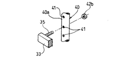
この縦支持部材40の側面40aには、この縦支持部材40延設方向に沿って複数の開口41…が、所定間隔をおいて形成されている。
【0040】
この開口41のうち、何れか一つには、ベルト留め具42が、裏面側から突設された雄ネジ部42aを、この開口41へ挿通すると共に、反対側側面からナット部材42bを螺合させて着脱自在となるように取り付けられている。
【0041】
このベルト留め具42には、シートベルト43,44のベルト端部に設けられた環状取付部43a,44aを係止する係止頭部42cが、一体に突設されている。
【0042】
また、この便器本体2の側方には、手摺33が延設されている。
【0043】
手摺33は、回転ヒジ機構を内蔵しており上下に回動可能になされている。また、手摺33に設けられた雄ネジ部35を開口41へ挿通するとともに反対側からナット部材を螺合させて着脱自在となるように縦支持部材40に取り付けられる。
【0044】
次に、この実施の形態2の作用について説明する。
【0045】
このように構成された実施の形態2のトイレ構造では、前記ベルト留め具42の係止頭部42cに、上半身固定用のシートベルト43,44の端部の環状取付部43a,44aを装着して、便器本体2の便座3に腰掛けた使用者の上半身を固定することが出来る。
【0046】
このため、長時間、座位で姿勢を保つことが出来ると共に、身体が前のめりになったり、臀部が便座前方にズレてしまう虞が無い。
【0047】
また、この実施の形態2では、前記ベルト留め具42の上下方向位置を、前記開口41の選択により変更可能であるので、利用者の体型に合わせて調整可能である。なお、前記手摺33も同様に上下方向位置を変更可能である。
【0048】
他の構成、及び作用効果については、前記実施の形態1と略同様であるので、説明を省略する。
【0049】
【変形例1】
図15は、この発明の実施の形態2の変形例1のトイレ構造を示すものである。なお、前記実施の形態2と同一乃至均等な部分については同一符号を付して説明する。
【0050】
この変形例1のトイレ構造では、上側支持部114、下側支持部115及び縦支持部140が一体に構成された門形のフレーム部材45が、上,下両端部に設けられた取付フランジ部114a,115aを、前記側壁13に対して取付ネジ46,46で固定することにより取り付けられている。
【0051】
このうち、前記縦支持部140の側面40aには、この縦支持部140延設方向に沿って複数の開口41…が、所定間隔をおいて形成されている。
【0052】
そして、この縦支持部140には、手摺33を回転ヒンジ機構34を介して回動自在に支持するスライド部材150が、上下方向に沿って摺動自在になるように設けられている。
【0053】
このスライド部材150には、取付孔150a,150aが形成されていて、ボルト160,160及びナット170,170によって前記開口41,41のいづれかに挿通固着されるように構成されている。
【0054】
次に、この変形例1の作用について説明する。
【0055】
この変形例1では、前記スライド部材150の上下方向へのスライド移動によって、手摺33位置を変更可能であるので、利用者の体型に合わせて調整可能である。
【0056】
他の構成、及び作用効果については、前記実施の形態2と略同様であるので、説明を省略する。
【0057】
【変形例2】
図16は、この発明の実施の形態2の変形例2のトイレ構造を示すものである。なお、前記実施の形態2と同一乃至均等な部分については同一符号を付して説明する。
【0058】
この変形例2のトイレ構造では、上側支持部材14、下側支持部材15間に架け渡されて、背もたれ部材200が設けられている。
【0059】
この背もたれ部材200の側面部には、延設方向に沿って複数の開口41…が、所定間隔をおいて形成されている。
【0060】
この開口41…のうち、何れか一つには、ベルト留め具42が、着脱自在となるように取り付けられている。
【0061】
次に、この変形例2の作用について説明する。
【0062】
この変形例2では、前記ベルト留め具42の上下方向位置を、前記開口41の選択により変更可能であるので、利用者の体型に合わせて調整可能である。
【0063】
他の構成、及び作用効果については、前記実施の形態1と略同様であるので、説明を省略する。
【0064】
以上、この発明の実施の形態を図面により詳述してきたが、具体的な構成はこの実施の形態に限らず、この発明の要旨を逸脱しない範囲の設計の変更等があってもこの発明に含まれる。
【0065】
例えば、背もたれ部7は、上側支持部材14又は下側支持部材15の片方または両方に回動可能なように軸支させても良い。また、上側支持部材14および下側支持部材15の両方ともスライド可能としても良い。
【0066】
【発明の効果】
以上説明してきたように、請求項1の発明によれば、前記背もたれ部は、前記上側支持部材又は下側支持部材の何れか一方に回動可能に軸支されているので傾斜角度の調整を行うことができる。また、上側支持部材または下側支持部材は、他方に対してスライド可能なので、背もたれ部の前後の位置を調整することができる。また、少なくとも、上下の2箇所で背もたれ部を支持しているため作用する力を分散させることができるので、上側支持部材および下側支持部材には負荷がかからない。
【0067】
ここで背もたれ部は、上側支持部材および下側支持部材の両方に回動自在に取付けても良い。また、上側支持部材および下側支持部材の両方とも伸縮動可能としても良い。
【0068】
また、前記背もたれ部が、角度調整可能であるので、着座者が、腰が曲らない高齢者や片麻痺などで膝を伸縮することができない身体障害者など、腰を曲げて座位姿勢を保持することが困難な者であっても、最適な座位姿勢を保持できるように設定することができる。
【0069】
また、請求項2の発明によれば、便器本体の側方に延設されるよう、床面からの高さがほぼ630mm〜680mmの手摺を併設したので、410mm〜450mmの座面高さを有する一般的な便座に着座した時の肘の位置に適合し、安定して肘を支持させることができるようになる。
【0070】
そして、請求項3に記載されたものでは、前記ベルト留め具に、上半身固定用のベルトを装着して、便器本体に腰掛けた使用者の上半身を固定することが出来る。
【0071】
このため、長時間、座位で姿勢を保つことが出来ると共に、身体が前のめりになったり、臀部が便座前方にズレてしまう虞が無い。
【0072】
また、使用者の体型に合わせて、ベルトと手摺の位置を最適なところに設定することができる、という実用上有益な効果を発揮し得る。
【図面の簡単な説明】
【図1】本発明の実施の形態1の全体側面図である。
【図2】図1の正面図である。
【図3】図1の平面図である。
【図4】(a)は背もたれ部の側面図、(b)は背もたれ部の正面図、(c)は(b)のA−A断面図、(d)は(b)のB−B断面図である。
【図5】図1の部分拡大図である。
【図6】図5の平面図である。
【図7】図6の背面図である。
【図8】背もたれ部背面上部の取付け構造を示す側方断面図である。
【図9】背もたれ部背面下部の取付け構造を示す側方断面図である。
【図10】下側支持部材の縦断面図である。
【図11】本発明の実施の形態2のトイレ構造で、ベルト留め具の取付を説明する斜視図である。
【図12】実施の形態2のトイレ構造の全体の構成を説明する側面図である。
【図13】実施の形態2のトイレ構造で、(a)は、ベルト留め具の取付を説明する斜視図で、(b)は、(a)中C−C線に沿った位置での断面図である。
【図14】実施の形態2のトイレ構造で、手摺の付け根部分の拡大斜視図である。
【図15】実施の形態2の変形例1のトイレ構造を示し、一部の構成を表す側面図である。
【図16】実施の形態2の変形例2のトイレ構造を示し、全体の構成を表す斜視図である。
【符号の説明】
1 床面
2 便器本体
7 背もたれ部
14 上側支持部材
15 下側支持部材
32 高さ
33 手摺
40 縦支持部材
41 開口
42 ベルト留め具
200 背もたれ部材[0001]
BACKGROUND OF THE INVENTION
The present invention relates to a low-cost toilet structure provided with a large backrest capable of adjusting the front and rear positions and the inclination angle.
[0002]
[Prior art]
Conventional toilets, particularly toilets for welfare and nursing care, are provided with a backrest on the back side of the toilet body. For example, JP-A-8-187205 and JP-A-5-13670 disclose large-sized toilets. A toilet bowl with a backrest is disclosed.
[0003]
[Problems to be solved by the invention]
However, in such a conventional toilet, the large backrest cannot adjust the position of the front and back and the tilt angle, and even if the reclining can be adjusted, the large backrest is uniaxial. There is a problem in that it is costly because of the supporting structure.
[0004]
Furthermore, since the handrail provided in the toilet part is set to a height of 620 mm or 700 mm from the floor surface, the elbow when seated on a general toilet seat having a seat surface height of 410 mm to 450 mm is used. It was out of position and could not support the elbow stably.
[0005]
Accordingly, an object of the present invention is to solve the above problems and provide a low-cost toilet structure capable of adjusting the front and rear positions and the inclination angle even with a large backrest.
[0006]
[Means for Solving the Problems]
In order to solve the above-mentioned problems, in the invention described in
[0007]
According to the invention according to
[0008]
Here, the backrest portion may be rotatably attached to both the upper support member and the lower support member. Further, both the upper support member and the lower support member may be capable of extending and contracting.
[0009]
In addition, the angle of the backrest is adjustable, so that the seated person can hold the sitting posture by bending the waist, such as elderly people who cannot bend their backs or disabled persons who cannot stretch their knees due to hemiplegia, etc. Even a person who is difficult to do can be set so as to maintain an optimal sitting posture.
[0010]
The invention described in
[0011]
According to the invention according to
[0012]
According to a third aspect of the present invention, the vertical support member is provided on both sides of the toilet main body, and spans the upper support member and the lower support member, and is formed along the vertical support member. The toilet structure according to
[0013]
According to the third aspect of the present invention, the upper body of the user seated on the toilet bowl body can be fixed by attaching a belt for fixing the upper body to the belt fastener.
[0014]
For this reason, while being able to maintain a posture in a sitting position for a long time, there is no possibility that a body will turn forward and a hip will shift to the front of a toilet seat.
[0015]
In addition, the position of the belt and the handrail can be set to an optimum place according to the body shape of the user.
[0016]
DESCRIPTION OF THE
Hereinafter, a specific first exemplary embodiment of the present invention will be described together with illustrated examples.
[0017]
1 to 10 show a first embodiment of the present invention.
[0018]
As shown in FIGS. 1 to 3, a
[0019]
In this
[0020]
The
[0021]
As shown in FIGS. 5 and 6, the
[0022]
At this time, as shown in FIGS. 7 to 9, the
[0023]
The angle of the
[0024]
For this purpose, as shown in FIG. 10, the both
[0025]
Further, a
[0026]
Further, the rear end portion of the
[0027]
Next, the operation of the first embodiment will be described.
[0028]
Since the
[0029]
Since the
[0030]
In particular, the
[0031]
Further, the insertion amount of the both side arm portions 26 (outer cylinder) and the insertion end 27 (inner cylinder) of the
[0032]
At this time, between the
[0033]
The
[0034]
In this way, the angle of the
[0035]
Further, since the angle of the
[0036]
Further, since the
[0037]
11 to 16 show a toilet structure according to
[0038]
In the toilet structure according to the second embodiment,
[0039]
A plurality of
[0040]
In any one of the
[0041]
The
[0042]
A
[0043]
The
[0044]
Next, the operation of the second embodiment will be described.
[0045]
In the toilet structure according to the second embodiment configured as described above, the
[0046]
For this reason, while being able to maintain a posture in a sitting position for a long time, there is no possibility that a body will turn forward and a hip will shift to the front of a toilet seat.
[0047]
Moreover, in this
[0048]
Other configurations and operational effects are substantially the same as those of the first embodiment, and thus description thereof is omitted.
[0049]
[Modification 1]
FIG. 15 shows a toilet structure of
[0050]
In the toilet structure according to the first modification, the gate-shaped
[0051]
Among these, a plurality of
[0052]
The
[0053]
Mounting
[0054]
Next, the effect | action of this
[0055]
In the first modification, the position of the
[0056]
Other configurations and operational effects are substantially the same as those of the second embodiment, and thus description thereof is omitted.
[0057]
[Modification 2]
FIG. 16 shows a toilet structure of
[0058]
In the toilet structure of the second modified example, a
[0059]
A plurality of
[0060]
A
[0061]
Next, the effect | action of this
[0062]
In the second modified example, the vertical position of the
[0063]
Other configurations and operational effects are substantially the same as those of the first embodiment, and thus description thereof is omitted.
[0064]
The embodiment of the present invention has been described in detail with reference to the drawings. However, the specific configuration is not limited to this embodiment, and the present invention can be changed even if there is a design change or the like without departing from the gist of the present invention. included.
[0065]
For example, the
[0066]
【The invention's effect】
As described above, according to the first aspect of the present invention, the backrest portion is pivotally supported by one of the upper support member and the lower support member so that the inclination angle can be adjusted. It can be carried out. Moreover, since the upper side support member or the lower side support member is slidable with respect to the other, the position before and behind the backrest part can be adjusted. In addition, since the acting force can be dispersed because the backrest portion is supported at least in two places, the upper support member and the lower support member are not loaded.
[0067]
Here, the backrest portion may be rotatably attached to both the upper support member and the lower support member. Further, both the upper support member and the lower support member may be capable of extending and contracting.
[0068]
In addition, the angle of the backrest is adjustable, so that the seated person can hold the sitting posture by bending the waist, such as elderly people who cannot bend their backs or disabled persons who cannot stretch their knees due to hemiplegia, etc. Even a person who is difficult to do can be set so as to maintain an optimal sitting posture.
[0069]
Further, according to the invention of
[0070]
In the third aspect of the present invention, an upper body fixing belt can be attached to the belt fastener to fix the upper body of the user sitting on the toilet body.
[0071]
For this reason, while being able to maintain a posture in a sitting position for a long time, there is no possibility that a body will turn forward and a hip will shift to the front of a toilet seat.
[0072]
Further, it is possible to exert a practically beneficial effect that the position of the belt and the handrail can be set to an optimum place according to the body shape of the user.
[Brief description of the drawings]
FIG. 1 is an overall side view of a first embodiment of the present invention.
FIG. 2 is a front view of FIG. 1;
3 is a plan view of FIG. 1. FIG.
4A is a side view of the backrest portion, FIG. 4B is a front view of the backrest portion, FIG. 4C is a cross-sectional view taken along line AA in FIG. 4B, and FIG. FIG.
FIG. 5 is a partially enlarged view of FIG. 1;
6 is a plan view of FIG. 5. FIG.
7 is a rear view of FIG. 6. FIG.
FIG. 8 is a side sectional view showing a mounting structure of the back upper part of the backrest part.
FIG. 9 is a side cross-sectional view showing a mounting structure for a lower back portion of a backrest portion.
FIG. 10 is a longitudinal sectional view of a lower support member.
FIG. 11 is a perspective view illustrating attachment of a belt fastener in the toilet structure according to the second embodiment of the present invention.
FIG. 12 is a side view illustrating the overall configuration of the toilet structure according to the second embodiment.
13 (a) is a perspective view illustrating attachment of a belt fastener, and FIG. 13 (b) is a cross-sectional view taken along a line CC in FIG. 13 (a). FIG.
14 is an enlarged perspective view of a base portion of a handrail in the toilet structure of the second embodiment. FIG.
FIG. 15 is a side view showing a toilet structure of a first modification of the second embodiment and showing a part of the configuration.
FIG. 16 is a perspective view showing a whole structure of a toilet structure according to a second modification of the second embodiment.
[Explanation of symbols]
DESCRIPTION OF
Claims (3)
前記背もたれ部は、回動可能なように前記上側支持部材又は下側支持部材の何れか一方に軸支され、且つ、
前記上側支持部材または下側支持部材に対し、前記便器本体の前後方向へスライド可能になされていることを特徴とするトイレ構造。A toilet body, an upper support member and a lower support member provided on the rear side of the toilet body, and a backrest portion supported on the upper support member and the lower support member and provided on the rear surface side of the toilet body A toilet structure with
The backrest is pivotally supported by either the upper support member or the lower support member so as to be rotatable, and
A toilet structure characterized by being slidable in the front-rear direction of the toilet body relative to the upper support member or the lower support member.
Priority Applications (1)
| Application Number | Priority Date | Filing Date | Title |
|---|---|---|---|
| JP2000124466A JP3654815B2 (en) | 1999-10-05 | 2000-04-25 | Toilet structure |
Applications Claiming Priority (3)
| Application Number | Priority Date | Filing Date | Title |
|---|---|---|---|
| JP11-284696 | 1999-10-05 | ||
| JP28469699 | 1999-10-05 | ||
| JP2000124466A JP3654815B2 (en) | 1999-10-05 | 2000-04-25 | Toilet structure |
Publications (2)
| Publication Number | Publication Date |
|---|---|
| JP2001169968A JP2001169968A (en) | 2001-06-26 |
| JP3654815B2 true JP3654815B2 (en) | 2005-06-02 |
Family
ID=26555572
Family Applications (1)
| Application Number | Title | Priority Date | Filing Date |
|---|---|---|---|
| JP2000124466A Expired - Fee Related JP3654815B2 (en) | 1999-10-05 | 2000-04-25 | Toilet structure |
Country Status (1)
| Country | Link |
|---|---|
| JP (1) | JP3654815B2 (en) |
Families Citing this family (1)
| Publication number | Priority date | Publication date | Assignee | Title |
|---|---|---|---|---|
| JP7148458B2 (en) * | 2019-05-21 | 2022-10-05 | ナカ工業株式会社 | assistive device |
-
2000
- 2000-04-25 JP JP2000124466A patent/JP3654815B2/en not_active Expired - Fee Related
Also Published As
| Publication number | Publication date |
|---|---|
| JP2001169968A (en) | 2001-06-26 |
Similar Documents
| Publication | Publication Date | Title |
|---|---|---|
| US6378947B1 (en) | Seating system | |
| US6792633B1 (en) | Stretcher | |
| KR20010087303A (en) | Moving device | |
| US7159940B1 (en) | Eccentrically rotatable swivel seat device | |
| US20050077758A1 (en) | Collapsible chair with adjustable backrest | |
| JP3654815B2 (en) | Toilet structure | |
| JP5250793B2 (en) | wheelchair | |
| JP4318191B2 (en) | Multipurpose chair frame | |
| KR100435846B1 (en) | Chair for Rectification Vertebral Column | |
| JP2009297465A (en) | Handrail for toilet | |
| JP4214504B2 (en) | Wheelchair legrest | |
| JP4263979B2 (en) | Bathroom chair | |
| KR20110000141U (en) | Multi-positioning chair | |
| JP4496389B2 (en) | Transfer device | |
| JP2000232995A (en) | System chair for helping | |
| US6233753B1 (en) | Hinged assembly for toilet seat construction | |
| WO2004098480A1 (en) | Calf rest for patient chair | |
| JP2008237583A (en) | Wheelchair for assistance and footrest assembly used therefor | |
| JP3144540B2 (en) | Safety frame for portable toilet | |
| KR200351807Y1 (en) | Chair for shower | |
| JP2021142222A (en) | Footrest and chair for person with impaired ability to maintain sitting posture | |
| JP7054290B1 (en) | Toilet railing device | |
| KR200380543Y1 (en) | Chair of sitting-down type | |
| JP2006340876A (en) | Reclining legless chair | |
| JPH11169321A (en) | Hand rail for toilet |
Legal Events
| Date | Code | Title | Description |
|---|---|---|---|
| A977 | Report on retrieval |
Free format text: JAPANESE INTERMEDIATE CODE: A971007 Effective date: 20050117 |
|
| TRDD | Decision of grant or rejection written | ||
| A01 | Written decision to grant a patent or to grant a registration (utility model) |
Free format text: JAPANESE INTERMEDIATE CODE: A01 Effective date: 20050202 |
|
| A61 | First payment of annual fees (during grant procedure) |
Free format text: JAPANESE INTERMEDIATE CODE: A61 Effective date: 20050301 |
|
| R151 | Written notification of patent or utility model registration |
Ref document number: 3654815 Country of ref document: JP Free format text: JAPANESE INTERMEDIATE CODE: R151 |
|
| FPAY | Renewal fee payment (event date is renewal date of database) |
Free format text: PAYMENT UNTIL: 20080311 Year of fee payment: 3 |
|
| FPAY | Renewal fee payment (event date is renewal date of database) |
Free format text: PAYMENT UNTIL: 20090311 Year of fee payment: 4 |
|
| FPAY | Renewal fee payment (event date is renewal date of database) |
Free format text: PAYMENT UNTIL: 20100311 Year of fee payment: 5 |
|
| FPAY | Renewal fee payment (event date is renewal date of database) |
Free format text: PAYMENT UNTIL: 20100311 Year of fee payment: 5 |
|
| FPAY | Renewal fee payment (event date is renewal date of database) |
Free format text: PAYMENT UNTIL: 20110311 Year of fee payment: 6 |
|
| FPAY | Renewal fee payment (event date is renewal date of database) |
Free format text: PAYMENT UNTIL: 20110311 Year of fee payment: 6 |
|
| FPAY | Renewal fee payment (event date is renewal date of database) |
Free format text: PAYMENT UNTIL: 20120311 Year of fee payment: 7 |
|
| FPAY | Renewal fee payment (event date is renewal date of database) |
Free format text: PAYMENT UNTIL: 20120311 Year of fee payment: 7 |
|
| FPAY | Renewal fee payment (event date is renewal date of database) |
Free format text: PAYMENT UNTIL: 20130311 Year of fee payment: 8 |
|
| FPAY | Renewal fee payment (event date is renewal date of database) |
Free format text: PAYMENT UNTIL: 20140311 Year of fee payment: 9 |
|
| LAPS | Cancellation because of no payment of annual fees |