JP3601068B2 - Radiator mounting structure - Google Patents
Radiator mounting structure Download PDFInfo
- Publication number
- JP3601068B2 JP3601068B2 JP33048693A JP33048693A JP3601068B2 JP 3601068 B2 JP3601068 B2 JP 3601068B2 JP 33048693 A JP33048693 A JP 33048693A JP 33048693 A JP33048693 A JP 33048693A JP 3601068 B2 JP3601068 B2 JP 3601068B2
- Authority
- JP
- Japan
- Prior art keywords
- radiator
- bracket
- mounting structure
- vehicle
- uneven
- Prior art date
- Legal status (The legal status is an assumption and is not a legal conclusion. Google has not performed a legal analysis and makes no representation as to the accuracy of the status listed.)
- Expired - Fee Related
Links
Images


Classifications
-
- F—MECHANICAL ENGINEERING; LIGHTING; HEATING; WEAPONS; BLASTING
- F28—HEAT EXCHANGE IN GENERAL
- F28F—DETAILS OF HEAT-EXCHANGE AND HEAT-TRANSFER APPARATUS, OF GENERAL APPLICATION
- F28F2275/00—Fastening; Joining
- F28F2275/14—Fastening; Joining by using form fitting connection, e.g. with tongue and groove
- F28F2275/143—Fastening; Joining by using form fitting connection, e.g. with tongue and groove with pin and hole connections
Landscapes
- Cooling, Air Intake And Gas Exhaust, And Fuel Tank Arrangements In Propulsion Units (AREA)
Description
【0001】
【産業上の利用分野】
本発明は、自動車に搭載するラジエータの取付構造に関するものである。
【0002】
【従来の技術】
従来より、車両側部材にラジエータを取付ける装置としては、真鍮製あるいは樹脂製のタンクにブラケットを介して車両側部材に取付ける構造が一般的である。
例えば図9に示す従来のラジエータは、タンク1の端部に形成される傾斜側面1aにこの傾斜側面1aに沿った傾斜板2aが一体成形されるブラケット2をハンダ付けするものである。
【0003】
図10に示す従来のラジエータは、タンク1の端部に形成される側板1bにブラケット2のボルト孔2bにボルト3を挿通しナット4を締め付けてタンク1にブラケット2を固定するものである。
図11に示す従来のラジエータは、車両側部材5にタンク1を取付ける場合ブラケット6のゴム部7をタンク1に嵌合固定しボルト孔9に挿通するボルト8により車両側部材5にブラケット6を固定するものである。
【0004】
【発明が解決しようとする課題】
しかし、図9および図10に示す従来のものでは、ラジエータコア部を構成するチューブ10とブラケット2との材質の違いにより熱膨張差が大きいため、チューブ10の端部の付け根部に熱応力による亀裂が発生しやすく、この亀裂が発生するとタンク1内の水漏れが発生するという問題がある。例えば図12に示すように、チューブ10とフィン11とで形成されるラジエータコア部のチューブ10の端部10aがタンク1の下面を構成するプレート12aに挿通され、この端部10aの周囲のチューブ付け根部13でプレート12とチューブ10とが固定されている。このチューブ付け根部13において、ブラケット2とチューブ10の伸長方向すなわち図12に示す上下方向の熱膨張差による伸長変位量の差により亀裂が発生し、この亀裂部分から水漏れが発生するのである。
【0005】
また図11に示す従来のラジエータでは、近年の車両ボンネットのスラントノーズ化の要求に対応するため、車両の前方に搭載されるラジエータの高さを低くしようとすると、ブラケット6の取付スペースが不足するという問題がある。
本発明はこのような問題点を解決するためになされたもので、ラジエータの熱歪み吸収を可能にしかつラジエータ上下の余裕小スペース空間内に取付け可能なラジエータの取付構造を提供することを目的とする。
【0006】
【課題を解決するための手段】
前記目的を達成するための本発明によるラジエータの取付構造は、冷却水が通過する複数本のチューブと、前記チューブの両端部にそれぞれ接続される二つのタンク部とを有するラジエータを、ブラケットを介して前記ラジエータの側方に配される車両側部材に取付けるラジエータの取付構造であって、前記ラジータの前記二つのタンク部は、前記チューブ側に凹み、水平な段差部にそれぞれ形成される第1の凹凸部を有し、前記ブラケットは、上下方向に延び、前記ラジエータの側面に対向配置される側板と、前記ラジエータ側端部が開口し、前記二つのタンク部にそれぞれ取り付けられる第2の凹凸部が形成され、前記ラジエータ側へと略水平方向に延びる平板部と、上下方向に延び、前記側板から垂直方向に曲折され、前記車両側部材に固定される取付け側板とを有し、前記ラジエータの前記第1の凹凸部に取付けられた弾性部材は前記第2の凹凸部の開口に挿入されて前記第2の凹凸部に組み付けられていることを特徴とする。
【0007】
【作用および発明の効果】
本発明のラジエータの取付構造によると、弾性部材をラジエータの各タンク部と車両側部材との間に取付けるため、ラジエータのチューブ長さ方向の歪みと車両側部材の長さ方向の歪みを前記弾性部材が吸収する。したがって、ラジエータおよびその取付具の材質、温度分布等の相違に起因する熱歪み、車両からの振動等によるラジエータの破損、水漏れ等が防止できる。しかも、ラジエータのタンク部の上下に小さな余裕スペースを確保してラジエータを車両側部材に固定することができる。
【0008】
【実施例】
以下、本発明の実施例を図面に基づいて説明する。
(第1実施例)
本発明の第1実施例を図1〜図4に示す。
ラジエータ20は、上タンク1と下タンク15の間にコア部を構成するチューブ10とフィン11とが交互に配設されている。上タンク1の平坦面1cには上方に突出するピン突起16が突き出しており、下タンク15の平坦面15cには下方向に突き出すピン突起17が設けられている。
【0009】
ピン突起16、17にゴムマウント21、22の挿入孔28が挿入される。このゴムマウント21、22の外周部には溝部27が全周に形成されている。
ゴムマウント21、22の溝部27にはブラケット30のU字溝30bが嵌合されている。ブラケット30は、側板30dがコア部の側板36の枠部37、38に対向して設けられる。側板30dの上端および下端には平板30aが形成され、この平板30aにU字溝30bが形成されている。この側板30dに垂直方向に曲折される取付け側板30cにはボルト孔33、34が形成されている。このボルト孔33、34にボルト31、32が挿入され、車両側部材35にブラケット30がネジ止め固定される。取付け側板30cの幅Lは車両側部材35の板幅よりも更に長い長さになっている。下タンク15のピン突起17に挿入されるゴムマウント22を介してブラケット30を固定する場合についても前記と同様である。
【0010】
組付け時、ラジエータ20の上タンク1、下タンク15のピン突起16、17にゴムマウント21、22の挿入孔28を挿入し、ゴムマウント21、22の溝部27にブラケット30のU字溝30bを挟み固定し、次いでブラケット30のボルト孔33、34にボルト31、32を挿入し、これらのボルト31、32を車両側部材35に締め付け固定する。
【0011】
この第1実施例によると、コア部を形成するチューブ10およびフィン11の長手方向の伸縮量とブラケット30の長手方向の伸縮量とに差がある場合、ゴムマウント21、22の溝部27の位置とU字溝30bとの位置移動により熱歪みによる吸収を行う。また、ゴムマウント21、22を使用していることから、車両側部材35からブラケット30を経由して伝達される振動がゴムマウント21、22で吸収されるため、ラジエータ20に与える振動が軽減される。さらには、上タンク1と、下タンク15の上下搭載スペースが小さくてすむ構造であるため、このようなラジエータ20を搭載する車両のスラントノーズ化に対応しやすいという利点がある。さらにまたブラケット30の取付け側板30cの幅Lを任意に決めることができるため、車両側部材35とラジエータ20との間の熱風回り込み防止用のシールの役割をブラケット30が果たす。そのため車両側部材35とラジエータ20間の熱風回り込み防止用シール部材を別途設ける必要がなく簡単な構成になるという効果がある。
【0012】
前記構成において、ピン突起16とゴムマウント21の挿入孔28、溝部27、U字溝30bの寸法関係は、組付け性の都合上、ゴムマウント21とブラケット30とを自由に可動するようにしてもよいし、固定するようにしてもよく、任意の寸法に選定可能である。またブラケット30の取付け側板30cの幅L寸法については、車両側部材35とラジエータ20との隙間をシールする手段としてこのブラケット30を用いる場合、熱風の回り込みを防止できるような任意の幅LにL寸法を選定できる。
【0013】
ラジエータ20は、温度変化を繰り返し受ける環境下にあるため、この温度変化の負荷に対しこの負荷を吸収するように、弾性部材からなるゴムマウント21、22をラジエータ取付用のブラケット30とラジエータコア部の間に介在させることにより、ラジエータコア部の伸びが吸収され、チューブ10の付け根部に発生する応力を低減させるため、このチューブ10の付け根部の破損破壊を防止し水漏れ等を防止することができる。
【0014】
ラジエータ20と車両側部材35との間から回り込む熱風を防止するため必要としていた従来の別部品を省略し、熱風回り込み防止部材に取付け用のブラケット30を代用できるため部品点数と取付工数の低減効果が大である。
(第2実施例)
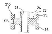
次に、本発明の第2実施例を図3および図4に示す。ゴムマウントの別形状の実施例を図3および図4に示す。このゴムマウント210は、車両振動を効果的に吸収するダッシュポットとして使用可能なダンパー形状のものである。ゴムマウント210は、円筒部24と、ツバ部23と、このツバ部23の外周端部に形成される環状フランジ25、26と、この環状フランジ25、26の間の外周部に形成される溝部27とから成る。この第2実施例によるエンジンマウント210を用いると、ピン突起16、17に挿入される挿入孔28の周囲にゴム材から成る円筒部24が支持されている構成であるから、前記図1に示す車両側部材からブラケット30を介してラジエータ20に伝達される車両振動を効果的に吸収する。
【0015】
(第3実施例)
次に本発明の第3実施例を図5に示す。図5に示す第3実施例は、ピン突起40とゴムマウント211との組み合わせにおいて、ゴムマウント211の挿入孔281が矩形状のもので、この矩形状の挿入孔281に対応して嵌合するようにピン突起40の形状が形成されている。
【0016】
この第3実施例では、エンジンマウント211の方向性が必要な場合、本実施例を適用することで、取付時あるいは使用時に良好に機能する。
(第4実施例)
本発明の第4実施例を図6に示す。図6に示す第4実施例は、ゴムマウントの形状をU字形状にした例である。この例では、ブラケット30のU字溝30bに嵌合するゴムマウント212の形状をU字状にした例である。図1に示すピン突起16に嵌合するゴムマウント212は、ピン突起16を嵌合可能なU字状溝部271を有し、外周部にブラケット30のU字溝30bが嵌合する溝部272を有する。
【0017】
この第4実施例では、先にゴムマウント212をブラケット30に組み付けた後、ブラケット30をラジエータ20に組み込む。また本実施例では、熱歪み吸収ならびにラジエータ上下スペース確保については前記第1実施例と同様である。
(第5実施例)
本発明の第5実施例を図7に示す。
【0018】
図7に示す第5実施例は、ラジエータの前後方向からブラケットを組み付ける構成にした例である。ブラケット300の平板300aに前後方向にU字溝300bが形成されている。
組付け時、ピン突起16にゴムマウント21の挿入孔28を挿入し、このゴムマウント21の溝部27にブラケット300のU字溝300bを組み付け固定する。
【0019】
(第6実施例)
本発明の第6実施例を図8に示す。
図8に示す第6実施例は、ラジエータ側に凹部、ゴムマウント側に前記凹部に嵌合可能な凸部を形成した例である。ラジエータ20の上タンク1の平坦面1cに凹部401が形成され、この凹部401に嵌合可能な凸部60がゴムマウント213の下面に形成されている。ゴムマウント213の外周部には溝部27が形成されている。
【0020】
この第6実施例によると、前記第1〜第5実施例と反対側の凹凸構成としたが、このような構成にしても熱歪み吸収とラジエータ取付スペースの縮小を可能にする。
【図面の簡単な説明】
【図1】本発明の第1実施例によるラジエータの取付け構造を示す組み立て分解斜視図である。
【図2】本発明の第1実施例によるラジエータの取付け構造の主要部を示す正面図である。
【図3】本発明の第2実施例によるゴムマウントの斜視図である。
【図4】図3に示すIV−IV 線断面図である。
【図5】本発明の第3実施例によるラジエータの取付け構造の主要部を示す斜視図である。
【図6】本発明の第4実施例によるラジエータの取付け構造の主要部を示す斜視図である。
【図7】本発明の第5実施例によるラジエータの取付け主構造の要部を示す斜視図である。
【図8】本発明の第6実施例によるラジエータの取付け構造の主要部を示す斜視図である。
【図9】従来のラジエータの取付け構造の主要部を示す斜視図である。
【図10】従来の他のラジエータの取付け構造の主要部を示す斜視図である。
【図11】従来の他のラジエータの取付け構造の主要部を示す斜視図である。
【図12】従来例の要部の断面図である。
【符号の説明】
1 上タンク(タンク部)
10 チューブ
11 フィン
15 下タンク(タンク部)
16 ピン突起(第1の凹凸部)
17 ピン突起(第1の凹凸部)
21 ゴムマウント(弾性部材)
22 ゴムマウント(弾性部材)
27 溝部(第2の凸凹部)
28 挿入孔(第1の凸凹部)
30 ブラケット
30a 平板
30b U字溝(第2の凹凸部)
30c 取付側板
30d 側板
31 ボルト
32 ボルト
35 車両側部材[0001]
[Industrial applications]
The present invention relates to a mounting structure for a radiator mounted on an automobile.
[0002]
[Prior art]
Conventionally, as a device for attaching a radiator to a vehicle-side member, a structure in which the radiator is attached to a vehicle-side member via a bracket in a brass or resin tank is generally used.
For example, the conventional radiator shown in FIG. 9 solders a
[0003]
The conventional radiator shown in FIG. 10 fixes the
In the conventional radiator shown in FIG. 11, when the tank 1 is mounted on the vehicle-side member 5, the rubber portion 7 of the bracket 6 is fitted and fixed to the tank 1, and the bracket 6 is attached to the vehicle-side member 5 by a bolt 8 inserted into a bolt hole 9. It is fixed.
[0004]
[Problems to be solved by the invention]
However, in the conventional device shown in FIGS. 9 and 10, a difference in thermal expansion is large due to a difference in material between the
[0005]
Further, in the conventional radiator shown in FIG. 11, in order to respond to the recent demand for a slant nose of the vehicle hood, if the height of the radiator mounted in front of the vehicle is reduced, the mounting space for the bracket 6 becomes insufficient. There is a problem.
The present invention has been made in order to solve such problems, and an object of the present invention is to provide a mounting structure of a radiator which enables thermal distortion absorption of the radiator and which can be mounted in a small space above and below the radiator. I do.
[0006]
[Means for Solving the Problems]
A radiator mounting structure according to the present invention for achieving the above object, a radiator having a plurality of tubes through which cooling water passes, and two tank portions respectively connected to both ends of the tubes , via a bracket. A radiator mounting structure for mounting to a vehicle-side member disposed on a side of the radiator, wherein the two tank portions of the radiator are recessed on the tube side and are formed in horizontal step portions, respectively. The bracket has a side plate that extends in the up-down direction and is disposed to face the side surface of the radiator, and a second protrusion and recess that is open at the radiator side end and is attached to each of the two tank portions. And a flat plate portion extending substantially horizontally to the radiator side, and extending vertically and bent vertically from the side plate to form the vehicle side member. And a mounting plate to be fixed, the first uneven portion attached elastic member of the radiator that is assembled to the second concave-convex portion is inserted into the opening of the second concave-convex portion It is characterized by.
[0007]
[Action and effect of the invention]
According to the mounting structure of the radiator of the present invention, to attach the elastic member between each tank portion and the vehicle-side member of the radiator, the strain in the length direction of the distortion and the vehicle-side member of the tube length direction of the radiator the The elastic member absorbs. Therefore, it is possible to prevent thermal distortion due to differences in the material, temperature distribution, and the like of the radiator and its attachment, breakage of the radiator due to vibration from a vehicle, water leakage, and the like. In addition, the radiator can be fixed to the vehicle-side member while securing a small extra space above and below the tank portion of the radiator.
[0008]
【Example】
Hereinafter, embodiments of the present invention will be described with reference to the drawings.
(First embodiment)
1 to 4 show a first embodiment of the present invention.
In the
[0009]
The
The U-shaped
[0010]
At the time of assembly, the
[0011]
According to the first embodiment, when there is a difference between the length of the
[0012]
In the above configuration, the dimensional relationship between the
[0013]
Since the
[0014]
Conventional separate parts required to prevent hot air from flowing between the
(Second embodiment)
Next, a second embodiment of the present invention is shown in FIGS. 3 and 4 show another embodiment of the rubber mount. The
[0015]
(Third embodiment)
Next, a third embodiment of the present invention is shown in FIG. In the third embodiment shown in FIG. 5, in the combination of the
[0016]
In the third embodiment, when the directionality of the
(Fourth embodiment)
FIG. 6 shows a fourth embodiment of the present invention. The fourth embodiment shown in FIG. 6 is an example in which the shape of the rubber mount is U-shaped. In this example, the shape of the
[0017]
In the fourth embodiment, after the
(Fifth embodiment)
FIG. 7 shows a fifth embodiment of the present invention.
[0018]
The fifth embodiment shown in FIG. 7 is an example in which a bracket is assembled from the front-rear direction of the radiator. A
At the time of assembly, the
[0019]
(Sixth embodiment)
FIG. 8 shows a sixth embodiment of the present invention.
The sixth embodiment shown in FIG. 8 is an example in which a concave portion is formed on the radiator side and a convex portion that can be fitted in the concave portion is formed on the rubber mount side. A
[0020]
According to the sixth embodiment, the concavo-convex configuration on the opposite side to the first to fifth embodiments is employed. However, even with such a configuration, it is possible to absorb thermal strain and reduce the radiator mounting space.
[Brief description of the drawings]
FIG. 1 is an exploded perspective view showing a mounting structure of a radiator according to a first embodiment of the present invention.
FIG. 2 is a front view showing a main part of a radiator mounting structure according to the first embodiment of the present invention.
FIG. 3 is a perspective view of a rubber mount according to a second embodiment of the present invention.
FIG. 4 is a sectional view taken along line IV-IV shown in FIG. 3;
FIG. 5 is a perspective view showing a main part of a radiator mounting structure according to a third embodiment of the present invention.
FIG. 6 is a perspective view showing a main part of a radiator mounting structure according to a fourth embodiment of the present invention.
FIG. 7 is a perspective view showing a main part of a main mounting structure of a radiator according to a fifth embodiment of the present invention.
FIG. 8 is a perspective view showing a main part of a radiator mounting structure according to a sixth embodiment of the present invention.
FIG. 9 is a perspective view showing a main part of a conventional radiator mounting structure.
FIG. 10 is a perspective view showing a main part of another conventional radiator mounting structure.
FIG. 11 is a perspective view showing a main part of another conventional radiator mounting structure.
FIG. 12 is a sectional view of a main part of a conventional example.
[Explanation of symbols]
1 upper tank (tank part)
10
16-pin protrusion (first uneven part)
17 Pin protrusion (first uneven part)
21 Rubber mount (elastic member)
22 Rubber mount (elastic member)
27 Groove (second convex and concave)
28 insertion hole (first convex and concave)
30 bracket <br/> 30a flat 30b U-shaped groove (second concave-convex portion)
30c Mounting
Claims (3)
前記ラジータの前記二つのタンク部は、前記チューブ側に凹み、水平な段差部にそれぞれ形成される第1の凹凸部を有し、
前記ブラケットは、
上下方向に延び、前記ラジエータの側面に対向配置される側板と、
前記ラジエータ側端部が開口し、前記二つのタンク部にそれぞれ取り付けられる第2の凹凸部が形成され、前記ラジエータ側へと略水平方向に延びる平板部と、
上下方向に延び、前記側板から垂直方向に曲折され、前記車両側部材に固定される取付け側板とを有し、
前記ラジエータの前記第1の凹凸部に取付けられた弾性部材は前記第2の凹凸部の開口に挿入されて前記第2の凹凸部に組み付けられていることを特徴とするラジエータの取付構造。A radiator for attaching a radiator having a plurality of tubes through which cooling water passes and two tank portions respectively connected to both ends of the tubes to a vehicle-side member disposed on a side of the radiator via a bracket Mounting structure,
The two tank portions of the radiator are recessed on the tube side, and have first uneven portions formed on horizontal step portions, respectively.
The bracket is
A side plate extending in the up-down direction and disposed to face the side surface of the radiator;
The radiator side end portion is open, a second uneven portion attached to each of the two tank portions is formed, a flat plate portion extending substantially horizontally to the radiator side,
A mounting side plate extending vertically and bent vertically from the side plate and fixed to the vehicle side member,
A mounting structure for a radiator, wherein an elastic member attached to the first uneven portion of the radiator is inserted into an opening of the second uneven portion and assembled to the second uneven portion .
前記弾性部材に形成された挿入孔に前記第1の凹凸部が挿入され、前記弾性部材の外周部に前記第2の凹凸部が嵌合されていることを特徴とする請求項1に記載のラジエータの取付構造。The first uneven portion has a pin shape protruding outward,
The said 1st uneven | corrugated part is inserted in the insertion hole formed in the said elastic member, The said 2nd uneven | corrugated part is fitted in the outer peripheral part of the said elastic member, The Claim of Claim 1 characterized by the above-mentioned. Radiator mounting structure.
Priority Applications (1)
| Application Number | Priority Date | Filing Date | Title |
|---|---|---|---|
| JP33048693A JP3601068B2 (en) | 1993-12-27 | 1993-12-27 | Radiator mounting structure |
Applications Claiming Priority (1)
| Application Number | Priority Date | Filing Date | Title |
|---|---|---|---|
| JP33048693A JP3601068B2 (en) | 1993-12-27 | 1993-12-27 | Radiator mounting structure |
Publications (2)
| Publication Number | Publication Date |
|---|---|
| JPH07186738A JPH07186738A (en) | 1995-07-25 |
| JP3601068B2 true JP3601068B2 (en) | 2004-12-15 |
Family
ID=18233169
Family Applications (1)
| Application Number | Title | Priority Date | Filing Date |
|---|---|---|---|
| JP33048693A Expired - Fee Related JP3601068B2 (en) | 1993-12-27 | 1993-12-27 | Radiator mounting structure |
Country Status (1)
| Country | Link |
|---|---|
| JP (1) | JP3601068B2 (en) |
Families Citing this family (9)
| Publication number | Priority date | Publication date | Assignee | Title |
|---|---|---|---|---|
| JPH1111348A (en) * | 1997-06-20 | 1999-01-19 | Aisin Seiki Co Ltd | Vehicle front end module structure |
| DE29711709U1 (en) * | 1997-07-04 | 1997-09-18 | Robert Bosch Gmbh, 70469 Stuttgart | Device for fastening at least one electropneumatic pressure transducer to components excited by vibration |
| KR100829884B1 (en) * | 2001-05-14 | 2008-05-16 | 한라공조주식회사 | Aluminum radiator |
| KR100444869B1 (en) * | 2002-07-15 | 2004-08-21 | 현대자동차주식회사 | Radiator structure |
| DE102004003197A1 (en) * | 2004-01-22 | 2005-08-25 | Bayerische Motoren Werke Ag | Fastening device for a heat exchanger |
| WO2009024062A1 (en) * | 2007-08-19 | 2009-02-26 | Caterpillar Inc. | A heat radiator assembly |
| CN102874101B (en) * | 2012-10-26 | 2016-04-06 | 湖南南车时代电动汽车股份有限公司 | A kind of radiator shock-dampening method and radiator |
| JP2018184940A (en) * | 2017-04-27 | 2018-11-22 | 株式会社ヴァレオジャパン | Tank fixing structure |
| KR102437469B1 (en) * | 2020-11-26 | 2022-08-30 | 쌍용자동차 주식회사 | Cooling Module Mounting Structure of Cars |
-
1993
- 1993-12-27 JP JP33048693A patent/JP3601068B2/en not_active Expired - Fee Related
Also Published As
| Publication number | Publication date |
|---|---|
| JPH07186738A (en) | 1995-07-25 |
Similar Documents
| Publication | Publication Date | Title |
|---|---|---|
| US4403648A (en) | Engine radiator support and guard assembly | |
| US6321495B1 (en) | Window device for use in a motor vehicle | |
| JP4502857B2 (en) | Mounting structure for vehicle heat exchanger | |
| JP3601068B2 (en) | Radiator mounting structure | |
| JP2005030570A (en) | Anti-vibration heat shield | |
| JP3119419B2 (en) | Fan shroud for heat exchanger | |
| JP2007055400A (en) | Front structure of vehicle | |
| JP4207665B2 (en) | Heat exchanger mounting structure | |
| JP2001080542A (en) | Mounting structure for heat exchanger for vehicle | |
| JP4665706B2 (en) | Cooling module | |
| KR102145514B1 (en) | Installing Structure of Cooling Module | |
| JPH09323554A (en) | Vibration-proof device of heat exchanger for vehicle | |
| KR100902734B1 (en) | Condenser mounting structure of the front end module | |
| JPH094453A (en) | Radiator | |
| JPH0329543Y2 (en) | ||
| JP4617976B2 (en) | Heat exchanger assembly | |
| JPS6036743Y2 (en) | Radiator support structure | |
| JP4562714B2 (en) | Anti-vibration support bracket | |
| JPH10148123A (en) | Integrated heat exchanger | |
| KR100528223B1 (en) | Mounting apparatus for side member of radiator | |
| JPH0755296Y2 (en) | Air cooler mounting structure | |
| JP2005329812A (en) | Heat exchanger module | |
| JPH028116Y2 (en) | ||
| KR960007746Y1 (en) | Cooling fixed plate of a car radiator | |
| KR20040024797A (en) | Radiator for vehicle front end module |
Legal Events
| Date | Code | Title | Description |
|---|---|---|---|
| A131 | Notification of reasons for refusal |
Free format text: JAPANESE INTERMEDIATE CODE: A131 Effective date: 20040220 |
|
| A521 | Written amendment |
Free format text: JAPANESE INTERMEDIATE CODE: A523 Effective date: 20040420 |
|
| A02 | Decision of refusal |
Free format text: JAPANESE INTERMEDIATE CODE: A02 Effective date: 20040614 |
|
| A521 | Written amendment |
Free format text: JAPANESE INTERMEDIATE CODE: A523 Effective date: 20040803 |
|
| A911 | Transfer of reconsideration by examiner before appeal (zenchi) |
Free format text: JAPANESE INTERMEDIATE CODE: A911 Effective date: 20040809 |
|
| TRDD | Decision of grant or rejection written | ||
| A01 | Written decision to grant a patent or to grant a registration (utility model) |
Free format text: JAPANESE INTERMEDIATE CODE: A01 Effective date: 20040831 |
|
| A61 | First payment of annual fees (during grant procedure) |
Free format text: JAPANESE INTERMEDIATE CODE: A61 Effective date: 20040913 |
|
| R150 | Certificate of patent or registration of utility model |
Free format text: JAPANESE INTERMEDIATE CODE: R150 |
|
| FPAY | Renewal fee payment (event date is renewal date of database) |
Free format text: PAYMENT UNTIL: 20101001 Year of fee payment: 6 |
|
| LAPS | Cancellation because of no payment of annual fees |