JP3179812U - 2つの開錠機構を有する錠前 - Google Patents
2つの開錠機構を有する錠前 Download PDFInfo
- Publication number
- JP3179812U JP3179812U JP2012003944U JP2012003944U JP3179812U JP 3179812 U JP3179812 U JP 3179812U JP 2012003944 U JP2012003944 U JP 2012003944U JP 2012003944 U JP2012003944 U JP 2012003944U JP 3179812 U JP3179812 U JP 3179812U
- Authority
- JP
- Japan
- Prior art keywords
- latch
- rib
- movable member
- lock
- contact
- Prior art date
- Legal status (The legal status is an assumption and is not a legal conclusion. Google has not performed a legal analysis and makes no representation as to the accuracy of the status listed.)
- Expired - Lifetime
Links
- 230000007246 mechanism Effects 0.000 title claims abstract description 18
- 238000003860 storage Methods 0.000 claims description 17
- 238000003825 pressing Methods 0.000 claims description 10
- 230000000994 depressogenic effect Effects 0.000 claims description 2
- 230000004308 accommodation Effects 0.000 description 5
- 239000011435 rock Substances 0.000 description 5
- 238000005516 engineering process Methods 0.000 description 2
- 238000004519 manufacturing process Methods 0.000 description 2
- 238000000034 method Methods 0.000 description 2
- 238000007796 conventional method Methods 0.000 description 1
- 230000002265 prevention Effects 0.000 description 1
Images


Landscapes
- Lock And Its Accessories (AREA)
Abstract
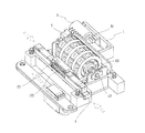
【解決手段】本考案の2つの開錠機構を有する錠前は、収容台1、可動部材2、シリンダ錠3、少なくとも1つのラッチ4、複数の数字盤5及び複数の軸部材6を含む。本考案は、数字盤5及びシリンダ錠3による開錠を行う機能を有するため、ユーザが数字盤5の開錠可能な数字を忘れても、鍵をシリンダ錠3に挿入することによって開錠することができる。
【選択図】図1
Description
11 収容槽
12 レール溝
121 弾性体
13 枢軸
2 可動部材
21 弾性部材
22 収容孔
23 凸リブ
24 押圧リブ
25 ストッパリブ
3 シリンダ錠
31 当接リブ
4 ラッチ
5 数字盤
51 貫通孔
511 凹溝
6 軸部材
61 係合溝
62 係合リブ
63 当接盤
7 本体
8 ツル
Claims (3)
- 収容台、可動部材、シリンダ錠、少なくとも1つのラッチ、複数の数字盤及び複数の軸部材を有する2つの開錠機構を有する錠前であって、
前記収容台には、収容槽及び少なくとも1つのレール溝が開設され、前記可動部材及び前記数字盤は、前記収容槽中に設けられ、前記可動部材底端には、少なくとも1つの弾性部材が設けられ、前記弾性部材両端は、前記可動部材と前記収容槽底部とに弾性当接され、前記可動部材上には、複数の収容孔が設けられ、前記数字盤は、前記収容孔中に嵌入され、
前記軸部材の一方の端部は、前記数字盤に貫設される上、前記数字盤に結合固定され、前記軸部材の他方の端部の外周には、係合溝が設けられ、前記数字盤及び前記軸部材には、枢軸が貫設され、前記枢軸両端は、前記収容台に結合位置決めされ、前記係合溝は、前記数字盤と前記数字盤との間から露出し、前記可動部材上には、前記係合溝に対応する複数の凸リブが設けられ、
前記ラッチの一方の端部は、前記レール溝外側の方向に突出し、前記ラッチの他方の端部には、弾性体が設けられ、前記弾性体両端は、前記ラッチと前記収容台とに弾性当接され、
前記シリンダ錠は、前記収容台上に枢設され、前記可動部材の一方の端部には、押圧リブが設けられ、前記シリンダ錠上には、前記押圧リブが当接される当接リブが設けられ、前記可動部材の他方の端部には、ストッパリブが設けられ、前記ストッパリブは、前記ラッチの側端に当接され
以上の構造により、前記係合溝と前記凸リブとが位置合わせされていない場合、前記凸リブが前記軸部材の外周によって押圧され、前記可動部材が前記弾性部材の弾性力に逆らって下方に移動し、前記ストッパリブが前記ラッチ側辺に当接され、前記ラッチを前記レール溝内に陥入できないため、施錠状態が保持され、
前記数字盤を回動し、前記各係合溝を対応する前記凸リブに位置合わせすると、前記可動部材が前記弾性部材の弾性力によって上方に移動し、前記ストッパリブが前記ラッチの側端から離脱するため、前記ラッチを押圧すると、前記弾性体の弾性力に逆らって前記ラッチを前記レール溝内に陥入させることができ、開錠状態となり、
前記施錠状態の際、ユーザが前記シリンダ錠中に鍵を挿入し、前記シリンダ錠を回転すると、前記当接リブが前記押圧リブを押圧し、前記可動部材端部の前記ストッパリブが上方に移動して前記ラッチ側端から離脱することにより、第2の開錠機能を有することを特徴とする2つの開錠機構を有する錠前。 - 前記数字盤の中央には、貫通孔が設けられ、前記貫通孔内壁には、少なくとも1つの凹溝が設けられ、前記軸部材外周には、前記少なくとも1つの凹溝に係合される係合リブが設けられ、前記軸部材の他方の端部には、前記数字盤の側部に当接される当接盤が設けられ、前記係合溝は、前記当接盤の外周に設けられることを特徴とする請求項1に記載の2つの開錠機構を有する錠前。
- 前記収容台には、対向する2つの前記レール溝が設けられ、前記各レール溝には、1つの前記ラッチが設けられ、前記弾性体両端は、前記2つのレール溝の前記ラッチに弾性当接されることを特徴とする請求項1又は2に記載の2つの開錠機構を有する錠前。
Applications Claiming Priority (2)
| Application Number | Priority Date | Filing Date | Title |
|---|---|---|---|
| TW100216997U TWM421970U (en) | 2011-09-09 | 2011-09-09 | Dual-mechanism lock core structure |
| TW100216997 | 2011-09-09 |
Publications (1)
| Publication Number | Publication Date |
|---|---|
| JP3179812U true JP3179812U (ja) | 2012-11-22 |
Family
ID=46459262
Family Applications (1)
| Application Number | Title | Priority Date | Filing Date |
|---|---|---|---|
| JP2012003944U Expired - Lifetime JP3179812U (ja) | 2011-09-09 | 2012-06-29 | 2つの開錠機構を有する錠前 |
Country Status (2)
| Country | Link |
|---|---|
| JP (1) | JP3179812U (ja) |
| TW (1) | TWM421970U (ja) |
Cited By (3)
| Publication number | Priority date | Publication date | Assignee | Title |
|---|---|---|---|---|
| CN103410383A (zh) * | 2013-08-15 | 2013-11-27 | 孙建华 | 一种密码锁 |
| CN105133942A (zh) * | 2015-06-12 | 2015-12-09 | 周明泉 | 一种字母数字机械密码锁 |
| WO2019136788A1 (zh) * | 2018-01-15 | 2019-07-18 | 浙江浦江梅花锁业集团有限公司 | 一种具有机械密码锁芯的智能挂锁 |
Families Citing this family (1)
| Publication number | Priority date | Publication date | Assignee | Title |
|---|---|---|---|---|
| CN103659743A (zh) * | 2012-08-30 | 2014-03-26 | 彰彬工業股份有限公司 | 工具锁 |
-
2011
- 2011-09-09 TW TW100216997U patent/TWM421970U/zh not_active IP Right Cessation
-
2012
- 2012-06-29 JP JP2012003944U patent/JP3179812U/ja not_active Expired - Lifetime
Cited By (3)
| Publication number | Priority date | Publication date | Assignee | Title |
|---|---|---|---|---|
| CN103410383A (zh) * | 2013-08-15 | 2013-11-27 | 孙建华 | 一种密码锁 |
| CN105133942A (zh) * | 2015-06-12 | 2015-12-09 | 周明泉 | 一种字母数字机械密码锁 |
| WO2019136788A1 (zh) * | 2018-01-15 | 2019-07-18 | 浙江浦江梅花锁业集团有限公司 | 一种具有机械密码锁芯的智能挂锁 |
Also Published As
| Publication number | Publication date |
|---|---|
| TWM421970U (en) | 2012-02-01 |
Similar Documents
| Publication | Publication Date | Title |
|---|---|---|
| US7892668B2 (en) | Battery locking apparatus for electronic device | |
| JP3179812U (ja) | 2つの開錠機構を有する錠前 | |
| US8254114B2 (en) | Battery cover structure for portable electronic device | |
| US20060213237A1 (en) | Padlock having a storage chamber | |
| US8302437B2 (en) | Locking assembly for a door | |
| US20090277233A1 (en) | Rekeyable lock cylinder and operating method thereof | |
| US20110154872A1 (en) | Rekeyable lock cylinder | |
| CN100573974C (zh) | 便携式电子装置电池盖结构 | |
| CN201725261U (zh) | 一种硬盘固定装置 | |
| GB2549863A (en) | Combination lock structure for simple password retrieval | |
| CN103838319A (zh) | 硬盘驱动器托盘和用于硬盘驱动器托盘的手柄组件 | |
| JP5094638B2 (ja) | 携帯型電子機器 | |
| JP4772655B2 (ja) | シリンダー錠 | |
| US8107237B2 (en) | Electronic device with latching assembly | |
| CN202117431U (zh) | 一种整合钥匙锁的指纹锁 | |
| CN211397041U (zh) | 一种千层锁 | |
| CN201804927U (zh) | 固定机构及具有该固定机构的电子装置 | |
| CN211258143U (zh) | 一种密码扣锁 | |
| CN211258144U (zh) | 密码扣锁 | |
| CN211342176U (zh) | 一种电机锁体的机械应急装置及电机锁体 | |
| CN211173468U (zh) | 一种双锁绳的物流密码锁 | |
| CN220562884U (zh) | 一种限位锁、基座和电池盒 | |
| CN201741157U (zh) | 电子装置及其与锁具的组合 | |
| CN215642782U (zh) | 一种加固平板微型防误触保护盖结构 | |
| CN110566043B (zh) | 一种双锁绳的物流密码锁 |
Legal Events
| Date | Code | Title | Description |
|---|---|---|---|
| A072 | Dismissal of procedure [no reply to invitation to correct request for examination] |
Free format text: JAPANESE INTERMEDIATE CODE: A073 Effective date: 20121016 |
|
| R150 | Certificate of patent or registration of utility model |
Ref document number: 3179812 Country of ref document: JP Free format text: JAPANESE INTERMEDIATE CODE: R150 Free format text: JAPANESE INTERMEDIATE CODE: R150 |
|
| FPAY | Renewal fee payment (event date is renewal date of database) |
Free format text: PAYMENT UNTIL: 20151031 Year of fee payment: 3 |
|
| A711 | Notification of change in applicant |
Free format text: JAPANESE INTERMEDIATE CODE: A711 Effective date: 20121107 |
|
| A521 | Request for written amendment filed |
Free format text: JAPANESE INTERMEDIATE CODE: A821 Effective date: 20121108 |
|
| A072 | Dismissal of procedure [no reply to invitation to correct request for examination] |
Free format text: JAPANESE INTERMEDIATE CODE: A072 Effective date: 20130312 |
|
| S111 | Request for change of ownership or part of ownership |
Free format text: JAPANESE INTERMEDIATE CODE: R323113 |
|
| R350 | Written notification of registration of transfer |
Free format text: JAPANESE INTERMEDIATE CODE: R350 |
|
| R250 | Receipt of annual fees |
Free format text: JAPANESE INTERMEDIATE CODE: R250 |
|
| R250 | Receipt of annual fees |
Free format text: JAPANESE INTERMEDIATE CODE: R250 |
|
| EXPY | Cancellation because of completion of term |