JP3178205U - Bolt fall-off prevention structure - Google Patents
Bolt fall-off prevention structure Download PDFInfo
- Publication number
- JP3178205U JP3178205U JP2012003786U JP2012003786U JP3178205U JP 3178205 U JP3178205 U JP 3178205U JP 2012003786 U JP2012003786 U JP 2012003786U JP 2012003786 U JP2012003786 U JP 2012003786U JP 3178205 U JP3178205 U JP 3178205U
- Authority
- JP
- Japan
- Prior art keywords
- bolt
- fastened
- split groove
- shaft portion
- hole
- Prior art date
- Legal status (The legal status is an assumption and is not a legal conclusion. Google has not performed a legal analysis and makes no representation as to the accuracy of the status listed.)
- Expired - Fee Related
Links
Images


Landscapes
- Connection Of Plates (AREA)
Abstract
【課題】別部品を必要とすることなく、容易な作業で、ボルトの脱落を確実に防止することができる、ボルトの脱落防止構造を提供すること。
【解決手段】ボルト1の雄ネジが形成された軸部3の先端側に、軸芯に沿って割り溝4を形成し、該ボルト1によって被締結物11,12を締結した後に、該ボルト1の軸部3の先端側を、上記割り溝4をポンチなどで押し開くことにより拡開させることを特徴とする、ボルトの脱落防止構造とした。
【選択図】 図3To provide a bolt drop-off prevention structure capable of reliably preventing a bolt from dropping off by an easy operation without requiring separate parts.
A split groove 4 is formed along the shaft core on the tip side of a shaft portion 3 on which a male screw of the bolt 1 is formed, and objects to be fastened 11 and 12 are fastened by the bolt 1, and then the bolt The tip end side of the shaft portion 3 is expanded by pushing open the split groove 4 with a punch or the like.
[Selection] Figure 3
Description
本考案は、振動などによりボルトが緩むことなく、その脱落を防止し得るボルトの脱落防止構造に関するものである。 The present invention relates to a bolt fall-off prevention structure that can prevent the bolt from coming off without being loosened by vibration or the like.
従来のボルトの一般的な使用方法を、図5および図6に示す。
図5では、締結すべき部材51,52に、それぞれ貫通孔51aおよび内周面に雌ネジの形成された貫通孔52aが形成されており、該貫通孔51a,52aにボルト53を挿入し、該ボルト53に形成された雄ネジを、部材52に形成された貫通孔52aの雌ネジに螺合することにより、部材51,52が締結されている。また、図6は、締結すべき部材51,52に、それぞれ貫通孔51aおよび52aが形成されており、該貫通孔51a,52aにボルト53を挿入し、該ボルト53に形成された雄ネジを、ナット54の雌ネジに螺合することにより、部材51,52が締結されている。
なお、ボルト53は、スパナ、六角レンチなどの工具で締め付けるのに適した形状である六角柱状の頭部53aと、外周面に雄ネジの形成された軸部53bを有する。
A general method of using a conventional bolt is shown in FIGS.
In FIG. 5, through-
The
ところで、図5および図6に示すように、ボルト53により部材51,52を締結したとしても、振動が加えられるような環境の下で長期間経過すると、振動によりボルトが緩み、ボルト53が部材51,52の貫通孔51a,52aから脱落しまうことがあった。
By the way, as shown in FIGS. 5 and 6, even if the
そこで、図7に示すように、ボルトの軸部53bの先端近傍に径方向に貫通孔53cを形成し、該貫通孔53cに割りピン55を挿入するようにしたボルトが提案されている。
かかるボルトにあっては、該ボルトによって被締結物を締結した後に、割りピン55が貫通孔53cに挿入され、その両端がボルトの軸部53bの外周面よりも外側に突出しているので、振動などが加えられてボルトが緩んだとしても、割りピン55が部材52の板面(ボルト53がナット54に螺合されている場合には、ナット54の端面)に当接して係止されるので、ボルト53の脱落が防止される。
Therefore, as shown in FIG. 7, a bolt is proposed in which a
In such a bolt, after the object to be fastened is fastened by the bolt, the
しかしながら、上述したボルトの脱落防止構造にあっては、付属品としての割りピン55を必要とするため、コストが高くつくとともに、割りピン55をボルト53に形成された貫通孔53cに挿入する作業は、手間がかかり、容易に行うことができるものではなかった。
However, since the above-described bolt drop-off preventing structure requires the
本考案は、上述した従来のボルトの脱落防止構造が有する欠点に鑑みなされたものであって、その目的は、別部品を必要とすることなく、容易な作業で、ボルトの脱落を確実に防止することができる、ボルトの脱落防止構造を提供することにある。 The present invention has been made in view of the drawbacks of the conventional bolt drop-off prevention structure described above, and its purpose is to reliably prevent bolt drop-off by an easy operation without requiring separate parts. An object of the present invention is to provide a structure for preventing the bolt from falling off.
上記した目的を達成するため、本考案は、ボルトの雄ネジが形成された軸部の先端側に、軸芯に沿って穴或いは割り溝を形成し、該ボルトによって被締結物を締結した後に、該ボルトの軸部の先端側を、上記穴或いは割り溝を押し開くことにより拡開させることを特徴とする、ボルトの脱落防止構造とした。 In order to achieve the above-described object, the present invention forms a hole or a split groove along the shaft core on the tip side of the shaft portion on which the male screw of the bolt is formed, and fastens an object to be fastened with the bolt. A bolt drop-off prevention structure is provided, in which the tip side of the shaft portion of the bolt is expanded by pushing open the hole or the split groove.
上記した本考案のボルトの脱落防止構造によれば、被締結物を締結した後に、該ボルトの軸部の先端側を、穴或いは割り溝をポンチなどで押し開くことにより拡開させ、ボルトの脱落防止が果たされるため、ボルト以外の別の部品を必要とせず、また、その作業は容易なものとなる。また、単にボルトの雄ネジが形成された軸部の先端側に、軸芯に沿って穴或いは割り溝を形成するのみであるため、その加工は容易で、安価に形成できる。 According to the bolt fall-off prevention structure of the present invention described above, after fastening an object to be fastened, the front end side of the shaft portion of the bolt is expanded by pushing open a hole or a split groove with a punch or the like. Since the drop-off prevention is achieved, no other parts other than bolts are required, and the operation is easy. Further, since the hole or split groove is simply formed along the shaft core on the tip end side of the shaft portion where the male screw of the bolt is formed, the processing is easy and inexpensive.
以下、上記した本考案に係るボルトの脱落防止構造の実施形態を、図面を示して詳細に説明する。 Hereinafter, embodiments of the bolt drop-off preventing structure according to the present invention will be described in detail with reference to the drawings.
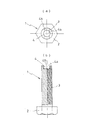
本考案に係るボルトの脱落防止構造を実現するボルトの一例を、図1に示す。
この図1に示したボルト1は、頭部2と、軸部3とを有する。頭部2は、略六角柱の形状をなし、スパナ、六角レンチなどの工具により締めつけるのに適した形状とされている。また、軸部3は、上記頭部2よりも小さな径を有する円柱状の形状をなし、その外周面には、雄ネジが形成されている。なお、この雄ネジは、軸部3の全長に渡り形成されている必要は必ずしもない。
An example of a bolt that realizes the bolt fall-off prevention structure according to the present invention is shown in FIG.
The bolt 1 shown in FIG. 1 has a
軸部3の先端側には、軸芯に沿って割り溝4が形成されている。この割り溝4は、軸部3の先端側が拡開変形し易いように形成されたものである。図示したボルト1にあっては、この割り溝4は、中心に形成された円柱形の穴部4aと、該円柱形の穴部4aの直径より狭い幅のスリット部4bとから構成され、中心に形成された円柱形の穴部4aが、ポンチなどの工具のガイド部としての作用を果たす。
A
上記ボルト1の使用し、被締結物を締結するに際しては、従来と同様に行えばよい。
すなわち、図2に示したように、締結すべき部材11,12に、それぞれ貫通孔11aおよび12aが形成されており、該貫通孔11a,12aにボルト1を挿入し、該ボルト1に形成された雄ネジを、ナット13の雌ネジに螺合することにより、部材11,12が締結される。
When the bolt 1 is used and the object to be fastened is fastened, it may be performed in the same manner as before.
That is, as shown in FIG. 2, through-
被締結物11,12をボルト1によって締結した後に、図3に示したように、突出したボルト1の軸部3の先端側を、該先端側に形成された上記割り溝4をポンチなどの工具Pを用いて押し開き、拡開させる。
このボルト1の軸部3の先端側の拡開作業は、割り溝4の存在により容易に行える。また図1の示したボルトの如く、割り溝4が、円柱形の穴部4aとスリット部4bとから構成されたものにあっては、中心に形成された円柱形の穴部4aが、ポンチなどの工具Pのガイド部として作用し、拡開が均等に行われる。
After fastening the objects to be fastened 11 and 12 with the bolt 1, as shown in FIG. 3, the front end side of the
The expanding operation on the front end side of the
ボルト1の軸部3の先端側が拡開されることにより、ナット13の緩みが拘束され、振動などが長時間加えられても、ボルト1が緩むことはなく、該ボルト1の脱落が防止される。
また、ボルト1の軸部3の先端側は、単に割り溝4の部分において折り曲げられて拡開されているだけであるため、ボルト1を取り外したい場合には、スパナ、六角レンチなどの工具を用いてボルト1或いはナット13を取り外し方向に回転させれば、その回転に伴って拡開部は縮小され、容易にボルトを取り外すことができる。
By expanding the front end side of the
Moreover, since the front end side of the
図4は、本考案に係るボルトの脱落防止構造を実現した他の実施形態を示した側面図である。この実施形態では、締結すべき部材21,22に、それぞれ貫通孔21aおよび内周面に雌ネジの形成された貫通孔22aが形成されており、該貫通孔21a,22aにボルト1を挿入し、該ボルト1に形成された雄ネジを、部材22に形成された貫通孔22aの雌ネジに螺合することにより、部材21,22が締結される。
FIG. 4 is a side view showing another embodiment that realizes the bolt drop-off preventing structure according to the present invention. In this embodiment, the through-
そして、被締結物を締結した後に、図4に示したように、突出したボルト1の軸部3の先端側を、該先端側に形成された割り溝4をポンチなどの工具Pを用いて押し開き、拡開させることにより、本考案に係るボルトの脱落防止構造が実現されている。
And after fastening a to-be-fastened thing, as shown in FIG. 4, the front end side of the
以上、本考案に係るボルトの脱落防止構造の実施形態を説明したが、本考案は、何ら既述の実施形態に限定されるものではなく、実用新案登録請求の範囲に記載した本考案の技術的思想の範囲内において、種々の変形および変更が可能であることは当然である。 The embodiment of the bolt drop-off prevention structure according to the present invention has been described above. However, the present invention is not limited to the embodiment described above, and the technology of the present invention described in the claims of the utility model registration. It goes without saying that various modifications and changes can be made within the scope of the technical idea.
例えば、上記実施形態においては、ボルト1の軸部3の先端側には、軸芯に沿って割り溝4を形成したものにつき説明したが、単に円柱形等の穴を形成したものとしてもよい。 また、上記実施形態においては、ボルトとして、頭部2が略六角柱の所謂六角ボルトを示したが、六角穴付きボルト、アイボルト、蝶ボルト、スタッドボルトなどであってもよい。
For example, in the above embodiment, the description has been given of the case where the
本考案に係るボルトの脱落防止構造は、振動が加えられる環境下において使用される部品の締結に用いられるボルト、例えば、自動車、船舶、さらにはモータを搭載した洗濯機等の家電製品の部品の締結に用いられるボルトに、広く利用することができる。 The bolt fall-off prevention structure according to the present invention is a bolt used for fastening parts used in an environment where vibration is applied, such as automobiles, ships, and parts of household electrical appliances such as washing machines equipped with motors. It can be widely used for bolts used for fastening.
1 ボルト
2 頭部
3 軸部
4 割り溝
4a 円柱形の穴部
4b スリット部
11,12 締結すべき部材
11a,12a 貫通孔
13 ナット
21,22 締結すべき部材
21a 貫通孔
22a 内周面に雌ネジの形成された貫通孔
P ポンチなどの工具
DESCRIPTION OF SYMBOLS 1
Claims (2)
Priority Applications (1)
| Application Number | Priority Date | Filing Date | Title |
|---|---|---|---|
| JP2012003786U JP3178205U (en) | 2012-06-22 | 2012-06-22 | Bolt fall-off prevention structure |
Applications Claiming Priority (1)
| Application Number | Priority Date | Filing Date | Title |
|---|---|---|---|
| JP2012003786U JP3178205U (en) | 2012-06-22 | 2012-06-22 | Bolt fall-off prevention structure |
Publications (1)
| Publication Number | Publication Date |
|---|---|
| JP3178205U true JP3178205U (en) | 2012-09-06 |
Family
ID=48004958
Family Applications (1)
| Application Number | Title | Priority Date | Filing Date |
|---|---|---|---|
| JP2012003786U Expired - Fee Related JP3178205U (en) | 2012-06-22 | 2012-06-22 | Bolt fall-off prevention structure |
Country Status (1)
| Country | Link |
|---|---|
| JP (1) | JP3178205U (en) |
Cited By (3)
| Publication number | Priority date | Publication date | Assignee | Title |
|---|---|---|---|---|
| CN110131281A (en) * | 2019-06-04 | 2019-08-16 | 贵州航天精工制造有限公司 | A kind of threaded fastener anti-loose method and structure |
| CN110947855A (en) * | 2019-11-27 | 2020-04-03 | 江苏天南电力器材有限公司 | Anti-dropping technology for fixing bolts of multi-split spacers and wire clips and their processing tools |
| JP2021156092A (en) * | 2020-03-30 | 2021-10-07 | 株式会社フジタ | One-touch fixing type lock bolt |
-
2012
- 2012-06-22 JP JP2012003786U patent/JP3178205U/en not_active Expired - Fee Related
Cited By (4)
| Publication number | Priority date | Publication date | Assignee | Title |
|---|---|---|---|---|
| CN110131281A (en) * | 2019-06-04 | 2019-08-16 | 贵州航天精工制造有限公司 | A kind of threaded fastener anti-loose method and structure |
| CN110947855A (en) * | 2019-11-27 | 2020-04-03 | 江苏天南电力器材有限公司 | Anti-dropping technology for fixing bolts of multi-split spacers and wire clips and their processing tools |
| JP2021156092A (en) * | 2020-03-30 | 2021-10-07 | 株式会社フジタ | One-touch fixing type lock bolt |
| JP7390958B2 (en) | 2020-03-30 | 2023-12-04 | 株式会社フジタ | One-touch lock bolt |
Similar Documents
| Publication | Publication Date | Title |
|---|---|---|
| US8931156B1 (en) | Puller for pulley of supercharger | |
| JP3187298U (en) | Double lock nut | |
| JP3178205U (en) | Bolt fall-off prevention structure | |
| JP3138476U (en) | Lock nut | |
| US8894334B2 (en) | Helical rolled ring bolt | |
| JP2017190793A (en) | Fall-off prevention device | |
| JP2012172780A (en) | Locking device for fastener | |
| JP6583721B2 (en) | Double nut and manufacturing method thereof | |
| JP3155204U (en) | Eccentric lock nut | |
| JP2015224771A (en) | Dropout prevention tool | |
| JP5825724B2 (en) | Shock absorber manufacturing method | |
| JP6231807B2 (en) | Bolt locking structure | |
| JP3179874U (en) | Fastener consisting of bolt and nut | |
| JP2017067252A (en) | Bolt/nut locking structure | |
| JP5556997B2 (en) | Friction fastener | |
| JP2000145742A (en) | Male screw member free from following turn | |
| JP2017106603A (en) | Fastening structure | |
| KR200426314Y1 (en) | Loosen Screw | |
| JP6446575B1 (en) | Nut device | |
| JP2017217706A (en) | Fastening structure and fastening tool | |
| JP6431739B2 (en) | Door handle mounting structure | |
| JP5079366B2 (en) | Rotating tool | |
| JP3037654U (en) | Loosening prevention bolt | |
| JP6720679B2 (en) | Fastening structure | |
| JP2000346035A (en) | Bolt with locking |
Legal Events
| Date | Code | Title | Description |
|---|---|---|---|
| R150 | Certificate of patent or registration of utility model |
Free format text: JAPANESE INTERMEDIATE CODE: R150 |
|
| FPAY | Renewal fee payment (event date is renewal date of database) |
Free format text: PAYMENT UNTIL: 20150815 Year of fee payment: 3 |
|
| LAPS | Cancellation because of no payment of annual fees |