JP3099175U - Packing and unpacking equipment for long fiber reinforced plastic reinforcement - Google Patents
Packing and unpacking equipment for long fiber reinforced plastic reinforcement Download PDFInfo
- Publication number
- JP3099175U JP3099175U JP2003004084U JP2003004084U JP3099175U JP 3099175 U JP3099175 U JP 3099175U JP 2003004084 U JP2003004084 U JP 2003004084U JP 2003004084 U JP2003004084 U JP 2003004084U JP 3099175 U JP3099175 U JP 3099175U
- Authority
- JP
- Japan
- Prior art keywords
- reinforced plastic
- turntable
- long fiber
- packing
- reinforcing material
- Prior art date
- Legal status (The legal status is an assumption and is not a legal conclusion. Google has not performed a legal analysis and makes no representation as to the accuracy of the status listed.)
- Expired - Lifetime
Links
Images


Landscapes
- Packaging Of Machine Parts And Wound Products (AREA)
Abstract
【課題】長尺の繊維強化プラスチック補強材を小型に梱包することができ、しかも開梱作業に要するスペースが少なくて済み、所望位置に該長尺の繊維強化プラスチック補強材を容易に展長させることを可能とする長尺繊維強化プラスチック補強材の梱包具及び梱包開梱装置を提供する。
【解決手段】巻き取られた長尺の繊維強化プラスチック補強材100をその上に保持し、ターンテーブル2上で回転されて長尺の繊維強化プラスチック補強材100がその上から引き出される梱包具1は、巻き取られた長尺の繊維強化プラスチック補強材100の側面100aが載置される表面11aを有する構成とする。
【選択図】 図1A long fiber-reinforced plastic reinforcing material can be packed in a small size, and a space required for unpacking work is small, and the long fiber-reinforced plastic reinforcing material is easily extended to a desired position. The present invention provides a packing device and a packing unpacking device for a long fiber reinforced plastic reinforcing material which enable the above.
A packaging device (1) holding a wound long fiber-reinforced plastic reinforcing material (100) thereon, and rotating on a turntable (2) to pull out the long fiber-reinforced plastic reinforcing material (100) therefrom. Has a surface 11a on which the side surface 100a of the wound long fiber-reinforced plastic reinforcing material 100 is placed.
[Selection diagram] Fig. 1
Description
【0001】
【考案の属する技術分野】
本考案は、プレート、ケーブル等の長尺の繊維強化プラスチック(FRP)補強材の梱包具及び梱包開梱装置に関するものである。
【0002】
【従来の技術】
従来、コンクリート構造物の補強方法として、既存或いは新設の構造物表面に、連続繊維補強材であるFRP製のプレート若しくはケーブルをプレストレス(緊張力)を導入して取り付けるFRP緊張工法がある。
【0003】
図13に、橋梁をFRP緊張工法により補強した例を示す。本例では、長尺のFRP補強材100にプレストレス(緊張力)を導入し、橋桁の下面に取り付けた態様を示す。
【0004】
斯かるFRP緊張工法に採用される長尺のFRP補強材100は、炭素繊維などとされる強化繊維シートにマトリクス樹脂を含浸させ硬化させたものであり、板状(シート状、テープ状若しくは紐状を含む。)、又は棒状(ケーブル)とされる(以下、総称して「FRPプレート」という。)。このFRPプレート100の両端には、通常、金属(例えば鋼製)或いはプラスチックの定着体101が接着剤などで固定されており、FRPプレート100は、ジャッキなどの緊張装置により緊張力を導入した状態で、定着体101を介してアンカーボルトにて補強箇所に固定される。
【0005】
このようなFRPプレート100で、例えば長さ5mを超えるような長尺のものを運搬する場合、FRPプレート100そのものをリールを用いず独立して円形に巻き取るか、リールに巻き取るかして小型化する方法がある。
【0006】
【考案が解決しようとする課題】
しかしながら、リールを用いない場合、重量増加は少なく梱包容積も小型であるが、FRPプレート100の両端に鋼製の定着体101などが固定されている場合、梱包が困難で、輸送中にFRPプレート100が折れるなどの損傷を与える虞があった。又、FRPプレート100を橋梁の桁の補強材として使用する場合、工事現場で桁下に真っ直ぐ伸ばして設置する必要があるが、地上又は足場板上に設置した円形に巻かれたFRPプレート100を展長するためには、その周りを作業者がFRPプレート100の一端を持って回り、展長させる必要があり、広い作業スペースを必要とする。
【0007】
一方、FRPプレート100をリールに巻き取った場合は、リール径が大きく輸送、保管時に広いスペースを必要とする。又、上記同様にFRPプレート100を橋梁の桁の補強材として用いる場合には、工事現場でFRPプレート100を展長する際に、リールを回転させるための装置が必要であり、吊り足場上などで作業することが困難であった。
【0008】
そのため、従来、両端に定着体がある場合などで、FRPプレート100に損傷を与えずに巻き取って梱包、開梱し、運搬することが困難な場合には、図14に示すように、荷台Cの長いトレーラー等で、FRPプレート100を伸ばしたまま運搬する必要があった。
【0009】
しかし、これでは輸送コストがかかるという問題があり、又輸送可能なFRPプレート100の長さも限られ、被補強構造物に応じた効果的な補強工事を行うことが困難であった。
【0010】
従って、本考案の目的は、長尺の繊維強化プラスチック補強材を小型に梱包することができ、しかも開梱作業に要するスペースが少なくて済み、所望位置に該長尺の繊維強化プラスチック補強材を容易に展長させることを可能とする長尺繊維強化プラスチック補強材の梱包具及び梱包開梱装置を提供することである。
【0011】
本考案の他の目的は、長尺の繊維強化プラスチック補強材の梱包物を軽量化、省スペース化することができ、該梱包物の保管・輸送コストの低減、保管・輸送作業性及び効率の向上を図ることのできる長尺繊維強化プラスチック補強材の梱包具及び梱包開梱装置を提供することである。
【0012】
更に、本考案の他の目的は、長尺の繊維強化プラスチック補強材の端部に定着体が固定されている場合にも損傷を与えることなく、しかも作業性良く長尺の繊維強化プラスチック補強材を梱包、開梱することができる長尺繊維強化プラスチック補強材の梱包具及び梱包開梱装置を提供することである。
【0013】
【課題を解決するための手段】
上記目的は本考案に係る長尺繊維強化プラスチック補強材の梱包具及び梱包開梱装置にて達成される。要約すれば、本考案は、巻き取られた長尺の繊維強化プラスチック補強材をその上に保持し、ターンテーブル上で回転されて前記長尺の繊維強化プラスチック補強材がその上から引き出される梱包具であって、巻き取られた長尺の繊維強化プラスチック補強材の側面が載置される表面を有することを特徴とする長尺繊維強化プラスチック補強材の梱包具である。
【0014】
本考案の一実施態様によると、長尺繊維強化プラスチック補強材の梱包具は、ターンテーブル上で回転されてその上に前記長尺の繊維強化プラスチック補強材が巻き取られる。
【0015】
本考案の一実施態様によると、長尺繊維強化プラスチック補強材の梱包具は更に、前記ターンテーブルの回転中心又は該回転中心に対し所定の相対位置に設けられたターンテーブル側位置決め手段と相対する位置に梱包具側位置決め手段を有する。一実施態様では、前記梱包具側位置決め手段は、前記ターンテーブル側位置決め手段と適合されることで当該梱包具の中心を前記ターンテーブルの回転中心に整合させる位置に設けられている。一実施態様では、前記ターンテーブル側位置決め手段は前記ターンテーブルの回転中心に突出して設けられた軸であり、前記梱包具側位置決め手段は当該梱包具の中心に設けられ前記軸を通す貫通孔又は前記軸を収める凹部である。他の実施態様では、前記ターンテーブル側位置決め手段は前記ターンテーブルの回転中心に対し所定の相対位置に配置された突起であり、前記梱包具側位置決め手段は前記ターンテーブル側位置決め手段と相対する位置に配置された突起である。他の実施態様では、前記ターンテーブル側位置決め手段は前記ターンテーブルの回転中心に対し所定の相対位置に配置された突起であり、前記梱包具側位置決め手段は前記ターンテーブル側位置決め手段と相対する位置に配置された貫通孔又は凹部である。更に他の実施態様では、前記ターンテーブル側位置決め手段は前記ターンテーブルの回転中心に対し所定の相対位置に配置された貫通孔又は凹部であり、前記梱包具側位置決め手段は前記ターンテーブル側位置決め手段と相対する位置に配置された突起である。
【0016】
本考案の一実施態様によると、長尺繊維強化プラスチック補強材の梱包具は更に、少なくとも巻き取られた前記長尺の繊維強化プラスチックの一方の端部を当該梱包具上に固定する固定手段を有する。一実施態様では、前記固定手段は、前記長尺の繊維強化プラスチック補強材の端部に設けられた定着体が嵌入される固定部である。又、本考案の一実施態様によると、少なくとも当該梱包具の前記固定部の位置において当該梱包具と前記ターンテーブルとを離間させる離隔部材を有する。
【0017】
本考案において、長尺繊維強化プラスチック補強材の梱包具は、積層紙、木材、金属、繊維強化プラスチック又はプラスチックで作成することができる。
【0018】
本考案の他の態様によると、上記本考案の長尺繊維強化プラスチック補強材の梱包具と、前記長尺繊維強化プラスチック補強材の梱包具を担持して回転可能なターンテーブルと、を有することを特徴とする長尺繊維強化プラスチック補強材の梱包開梱装置が提供される。
【0019】
【考案の実施の形態】
以下、本考案に係る長尺繊維強化プラスチック補強材の梱包具及び梱包開梱装置を図面に則して更に詳しく説明する。
【0020】
実施例1
先ず、図1及び図2を参照して、本発明に係る梱包具及び梱包開梱装置の一実施例について説明する。
【0021】
本実施例では、梱包開梱装置Aは、橋梁などの構造物のFRP緊張工法に用いられるFRPプレート100の梱包開梱用とされる。
【0022】
本考案によれば、軽量で省スペース性に優れた、平型の梱包具1と、小型ターンテーブル2と、を備える梱包開梱装置Aを用いることで、長尺のFRPプレート100を簡単に巻き取り、引き出し可能とする。つまり、図1及び図2に示すように、梱包開梱装置Aは、平型の梱包具(以下「パレット」という。)1と、上側テーブル20及び下側テーブル30を備えるターンテーブル2と、を有する。
【0023】
ターンテーブル2の上側テーブル20は、地面或いは吊り足場の足場板などに載置される下側テーブル30に対して、回転中心の回りを相対的に正逆両方向に回転移動可能とされている。これにより、上側テーブル20上に載置されたパレット1は、ターンテーブル2上で正逆両方向に回転することができ、その上にFRPプレート100を巻き取り、又その上からFRPプレート100を引き出すことができる。
【0024】
ここで、被梱包物たるFRPプレート100は、上述のように、強化繊維にマトリクス樹脂を含浸させ硬化させたものであり、板状(シート上、テープ状或いは紐状を含む。)、又は棒状(ケーブル)であってよい。強化繊維は、通常、FRPプレート100の長手方向、即ち、緊張力導入方向に沿って一方向に配列された一方向配列強化繊維とされ、場合によっては、編織されたクロスが使用される。
【0025】
FRPプレート100の強化繊維としては、一般に、PAN系或いはピッチ系炭素繊維、ガラス繊維、又は、アラミド、ナイロン、ポリエステル、PBOなどの有機繊維を一種、又は、複数種混入して使用される。又、強化繊維に含浸されるマトリクス樹脂としては、一般に、熱硬化性樹脂とされ、熱硬化性樹脂としては、常温硬化型或いは熱硬化型のエポキシ樹脂、ビニルエステル樹脂、MMA(メタクリル酸メチル)樹脂、又はフェノール樹脂が使用される。
【0026】
本実施例では、FRPプレート100は、強化繊維として一方向に配列された炭素繊維を使用した炭素繊維強化プラスチックで、断面が矩形とされる幅(W0)が50mm、厚さ(T0)が2mm、長さ(L)が5mの長尺(テープ状)のプレートであるものとする。
【0027】
以下、更に詳しく梱包開梱装置Aについて説明する。
【0028】
パレット1は、本実施例では、ほぼ一様に平坦な板状のパレット本体11から成る。そして、このパレット本体11の上側表面11aに、巻き取られたFRPプレート100の巻き取り側面100aが載置される。尚、長尺のFRP補強材がケーブルである場合など、その断面形状に応じた起伏がパレット1との接触部に生じ得るが、この部分も、ここでは全体として面状の巻き取り側面として取り扱う。
【0029】
パレット1を形成する材料としては、積層紙(ダンボール)、木材、金属、FRP又はプラスチックなどを用いることができるが、パレット1自体、軽量で、人力で容易に運搬できるようにする(通常、重量1kg〜5kg)。積層紙や木材を利用した場合は、使用後は焼却処分が可能であるので好適である。
【0030】
パレット1のサイズは、被梱包物たる長尺のFRPプレート100の巻き取り直径にあわせて設定することができる。例えば、FRP緊張工法に用いられるFRPプレート100の梱包用である場合、通常、長手方向長さが3m〜100mとされるFRPプレート100の巻き取り直径が0.5m〜3mとされることから、パレット本体11の幅W1a、W1b(或いはパレット1が円形である場合直径)は0.5m〜3mとされる。運搬の容易さから、パレット本体11の幅W1a、W2bは1〜2mが好適である。又、用いる材料の強度等によって種々変更されるものであるが、巻き取られたFRPプレート100が載置されるパレット本体11の厚さT1は、通常、5mm〜100mmとされる。
【0031】
尚、パレット1の形状は、平板に限定されるものではなく、リブ、パイプ或いは角柱などの補強手段によって補強してもよい。
【0032】
ターンテーブル2は、パレット1が載置される上側テーブル20と、上側テーブル20がその上で回転される下側テーブル30とを有する。
【0033】
本実施例では、下側テーブル30は、ほぼ一様に平坦な板状の下側テーブル本体31と、回転軸32と、を備えてなる。一方、上側テーブル20は、ほぼ一様に平坦な板状の上側テーブル本体21の下面に、車輪(キャスター)22を複数備え、又、上側テーブル本体21は、その中心、通常、重心に回転軸受けたる上側テーブル貫通穴23を備えている。そして、この上側テーブル貫通孔23に、下側テーブル30の中心に突出して設けられた回転軸32を通すことにより、上側テーブル20の中心と下側テーブル30の中心が整合するように、上側テーブル20は下側テーブル30上に回転可能に配置される。本実施例では、車輪22は、回転軸32の周りで同一円周上を走行するように上側テーブル本体21の下面に8個、均等(対角上)に配置されている。
【0034】
上側テーブル本体21、下側テーブル本体31、更には回転軸32を形成する材料としては、適宜任意のものを用いる得るが、FRP緊張工法にて用いられるFRPプレート100の梱包開梱装置Aとして使用する場合、後述するように、工事現場、特に、吊り足場などに配置する際に、パレット1と同様、ターンテーブル2をも軽量(通常、重量1kg〜20kg)であることが望ましい。この点で、ターンテーブル2の上側テーブル本体21、下側テーブル本体31、更には回転軸を木材、プラスチックにて作製するのが好適である。
【0035】
上側テーブル20のサイズは、パレット2を安定して載置することができるように適宜設定し得る。例えば、FRP緊張工法に用いられるFRPプレート100の梱包用である場合、通常上述のようなサイズとされるパレット1を安定して載置し得るように、上側テーブル本体21の幅W2a、W2b(或いは上側テーブル本体21が円形である場合直径)は0.5m〜3mとされる。運搬の容易さ、パレット1の載置安定性から、上側テーブル本体21の幅W2a、W2bは0.5〜1.5mが好適である。又、用いる材料の強度等によって種々変更されるものであるが、上側テーブル本体21の厚さT2は、通常、5mm〜50mmとされる。
【0036】
下側テーブル30のサイズは、上側テーブル20の車輪22がその上を走行可能であり、又安定して地面或いは足場板などの設置場所に安定してターンテーブル2を設置できるように設定される。例えば、FRP緊張工法に用いられるFRPプレート100の梱包用である場合、通常上述のようなサイズとされる上側テーブル20に対して、下側テーブル本体31の幅W3a、W3b(或いは下側テーブル本体31が円形である場合直径)は0.5m〜3mとされる。運搬の容易さ、設置安定性から、下側テーブル本体31の幅W3a、W3bは0.5〜1.5mが好適である。又、用いる材料の強度等によって種々変更されるものであるが、下側テーブル本体31の厚さT3は、通常、5mm〜100mmとされる。
【0037】
尚、上側テーブル20に設ける車輪22は、上側テーブル本体21の強度などとの関係で、巻き取られたFRPプレート100が載置されたパレット1を支持し得るように、適当な強度のものを、適当な配置にて設ける。下側テーブル本体31が上述のようなサイズであれば、通常、車輪22は、上側テーブル20の回転中心(回転軸32の中心)から距離(半径)R=0.4〜2.9mの円周上を走行するように設ける。
【0038】
尚、上記パレット1と同様、ターンテーブル2の上側、下側テーブル20、30の形状は、平板に限定されるものではなく、例えば、箱形の中空断面であったり、リブ、パイプ或いは角柱などの補強手段で補強されていてもよい。
【0039】
ここで、本考案の好ましい一態様によれば、ターンテーブル2には、パレット1を中央に固定するターンテーブル側位置決め手段を設け、一方、パレット1には、これに相対する位置に梱包具側位置決め手段を設ける。ターンテーブル側位置決め手段は、ターンテーブル2の回転中心又は回転中心に対し所定の位置関係に設けられ、梱包具側位置決め手段は、ターンテーブル側位置決め手段と適合してパレット1の中心、通常、重心をターンテーブル2の回転中心に整合させる位置に設けられる。
【0040】
本実施例では、ターンテーブル2の下側テーブル30に設けられる回転軸32がターンテーブル側位置決め手段として機能する。つまり、上側テーブル20を下側テーブル30上に適切に配置することで、下側テーブル30の回転軸32は、上側テーブル20に設けられた上側テーブル貫通孔23を通して更に上方に突出する。
【0041】
そして、本実施例では、パレット本体11には、梱包具側位置決め手段として、上側テーブル貫通孔23を通して突出した回転軸32に相対する位置であって、パレット本体11の中心、通常、重心に、回転軸32を通すパレット貫通孔12を有する。
【0042】
このように、パレット1、ターンテーブル2に、それぞれ梱包具側位置決め手段、ターンテーブル側位置決め手段を設けることによって、パレット1は、ターンテーブル2上で中央からずれることがなく、容易に回転することができ、パレット1からFRPプレート100を引き出す際に、少ない引張力で引き出すことができる。又、FRPプレート100のパレット1への巻き込み、又パレット1からの引き出し作業時にパレット1がターンテーブル2から脱落することがなく、更にFRPプレート100に折れ曲がりが生じることをも防止することが可能となる。
【0043】
好ましくは、更に、少なくとも巻き取られたFRPプレート100一方の端部(例えば、巻き取り終端側の端部)をパレット1に固定する固定手段、或いは少なくとも一方の端部(例えば、巻き取り終端側の端部)を巻き取ったFRPプレート100の束に固定するか若しくは端部同士を固定する固定手段によって、FRPプレート100が自身の弾性力によって展長するのを阻止することができる。
【0044】
本実施例の梱包開梱装置Aの一具体例を示せば次の通りである。
・パレット1
材料:ダンボール
幅W1a:1.5m
幅W1b:1.5m
厚さT1:5mm(重量約2kg)
パレット貫通孔の内径D1:55mm
・上側テーブル20
本体21の材料:木材(ベニヤ板)
幅W2a:1m
幅W2b:1m
厚さT2:12mm(重量約6kg)
上側テーブル貫通孔の内径D2:55mm
車輪22の走行半径R:0.9m
・下側テーブル30
本体21の材料:木材(ベニヤ板)
幅W3a:1m
幅W3b:1m
厚さT3:12mm(重量6kg)
回転軸32の材料:木材
回転軸32の外径D3:50mm
回転軸32の高さH3:150mm
【0045】
以上、本実施例の梱包開梱装置Aによれば、極めて容易にFRPプレート100を梱包、開梱することができ、且つ、FRPプレートの損傷を防止することができる。
【0046】
実施例2
次に、図3及び図4を参照して、本考案に係る梱包開梱装置の他の実施例について説明する。本実施例の梱包開梱装置の基本構成は実施例1のものと同じであり、梱包具側位置決め手段及びターンテーブル側位置決め手段が異なる。従って、実施例1の梱包開梱装置と同一若しくは相当する機能、構成を有する要素には同一符号を付して詳しい説明は省略する。
【0047】
図3及び図4に示すように、本実施例のFRPプレート100の梱包開梱装置Aでは、ターンテーブル2の下側テーブル30の中心に上方に突出して設けられた回転軸32は、上側テーブル本体21の下面に下方に突出して設けられた回転軸受け24に回転可能に嵌合する。これにより、この回転軸受け24に回転軸32を収めることにより、上側テーブル20の中心と下側テーブル30の中心が整合するようになっている。
【0048】
そして、本実施例では、ターンテーブル側位置決め手段として、上側テーブル本体21の上面から上方に突出したターンテーブル側突起25を有する。図示の例では、ターンテーブル側突起25は、略正方形とされる上側テーブル本体21の4辺に沿ってそれぞれ延在する、所定幅、長さの棒状のガイドとされる。
【0049】
一方、パレット1は、梱包具側位置決め手段として、パレット本体11の下面から下方に突出したパレット側突起13を有する。パレット側突起13は、ターンテーブル側突起25に適合する位置に設けられ、図示の例では、略正方形のパレット本体11の4辺に沿って配置される、所定幅の連続した縁部とされる。
【0050】
4辺のパレット側突起13は、それぞれパレット1の中心からの距離(相対位置)d1が、上側テーブル20の回転中心からターンテーブル側突起25のそれぞれの外側側壁25aへの距離d2(相対位置)とほぼ等しくなる内側側壁13aを有し、これらの側壁を介してターンテーブル側突起25とパレット側突起13とが嵌り合うことで、パレット1の中心と上側テーブル20の回転中心とが整合され、パレット1と上側テーブル20の相対移動が阻止される。
【0051】
これによって、実施例1と同様、パレット1は、ターンテーブル2上で中央からずれることがなく、容易に回転することができる。又、FRPプレート100の、パレット1への巻き込み、パレット1からの引き出し作業時にパレット1がターンテーブル2から脱落することがない。更に、本実施例では、パレット1と上側テーブル20との相対移動が実質的に完全に阻止され、互いに滑ることもない。
【0052】
突起13、25は、それぞれパレット本体11、上側テーブル本体21と同質又は異質の材料で作成し、接着等の適当な手段によって取り付けることができる。
【0053】
尚、梱包具側位置決め手段、ターンテーブル側位置決め手段は、突起同士を適合させる態様に限定されるものではない。いずれかを貫通孔又は凹部として、他方を突起としてもよく、ターンテーブル2の回転中心に対するターンテーブル側位置決め手段の相対位置と、パレット1の中心に対する梱包具側位置決め手段の相対位置とが適合するようにこれら位置決め手段を設けることで、同様の効果を得ることができる。
【0054】
以上、本実施例の構成によっても、実施例1と同様に、極めて容易にFRPプレート100を梱包、開梱することができ、且つ、FRPプレートの損傷を防止することができる。
【0055】
実施例3
次に、図5及び図6を参照して、本考案に係る梱包開梱装置の更に他の実施例について説明する。本実施例の梱包開梱装置の基本構成は、実施例1、2にて説明したものと同じであり、特に、パレット1の構成と、ターンテーブル側及びパレット側の位置決め手段の構成に変更が加えられたものである。
【0056】
本実施例では、FRPプレート100の長手方向両端部に鋼製の定着体101a、101bが固定されている。図示するように、例えばFRP緊張工法に用いられるFRPプレート100の端部に取り付けられる定着体101は、FRPプレート100の幅W0よりも、同方向で広い幅W0’を有することが多い。こうした場合、一様に平坦なパレット本体11上に巻き取られたFRPプレート100の巻き取り側面100aを載置しようとすると、FRPプレート100の端部で定着体101がFRPプレート100の幅W0方向に突出しているために、巻き取り作業が困難となり、又巻き取ったFRPプレート100がパレット1上で不安定となったり、定着体101の固定部近傍などにおいてFRPプレート100が折れるなどの損傷が生じる虞がある。
【0057】
そこで、このように定着体101などの突起物がある場合には、図5及び図6に示すように、FRPプレート100を巻き取った状態でこの突起物に適合する位置のパレット本体11に、固定手段としてその形に合わせて形成された穴或いは凹部とされる固定部14を設ける。本例では、FRPプレート100の両端に設けられた定着体101a、101bに適合する固定部14a、14bを設ける。尚、FRPプレート100の両端部に設けられた定着体101a、101bを収める固定部14a、14bは、定着体101a、101bの重量のバランスをとるために、パレット本体11上で対角に設けるのが望ましい。但し、固定部の配置は何ら限定されるものではなく、FRPプレート100の長さなど、被梱包物に応じて任意の箇所に設定することが可能である。
【0058】
FRPプレート100の幅W0からの定着体101の突出量pが、パレット本体11の厚さT1以下であれば、固定部14a、14bは、パレット本体11に定着体101が収まる凹部若しくは貫通穴を設け、パレット本体11は、上側テーブル本体21の上面に載置すればよい。一方、定着体101の突出量pが、パレット本体11の厚さT1よいりも大きい場合には、パレット本体11の下面或いは上側テーブル20に、パレット本体11の下面と上側テーブル本体21の上面とを、少なくとも固定部14a、14bの位置において定着体101の突出部101pが収まるように十分に離間させる離隔部材15を設ける。
【0059】
これに限定されるものではないが、図示の例では、離隔部材15は、パレット本体11の下面に、パレット本体11の幅W1a方向に全幅にわたり延在する複数の縦材15aと、これと略直交するパレット本体11の幅W1b方向に全幅に渡り延在する複数の横材15bとを、この順に接着して、格子状としたものとされる。離隔部材15は、パレット本体11、上側テーブル21と同質又は異質の材料で形成することができる。本例では、離隔部材15aは、パレット1と同質のダンボールにて形成された所定の幅、高さを有する中空の角材とされる。ここでは、縦材15a、横材15bとして、断面が60mm×45mmのダンボール厚板角パイプを4本ずつ用いた。勿論、縦材15a、横材15bの形状、数は本実施例のものに限定されるものではなく、又例えば縦材15aのみを設ける構成としてもよい。
【0060】
尚、この角材にて形成される離隔部材15は、平板状のパレット本体11の補強効果をも有する。又、上述したように平板状のパレット本体11或いは上側テーブル20の補強のためにリブ或いはパイプなどの補強手段が設けられている場合であって、これによって少なくとも固定部14a、14bの位置においてパレット本体11と上側テーブル20本体21との間に、定着体101の突出部101pを収めるのに十分な間隙が形成されていれば、これらの補強手段は離隔部材としても機能する。更に、実施例2にて説明したパレット側位置決め手段及び/又はターンテーブル側位置決め手段として設けられる突起によって、少なくとも定着体101が配置される固定部14a、14bの位置においてパレット本体11の下面と上側テーブル本体21との間に、定着体101の突出部101pを収めるのに十分な間隙が形成されていれば、位置決め手段たるこの突起は離隔部材としても機能する。
【0061】
本実施例では、上側テーブル20と下側テーブル30は、それぞれ実施例2のものと同様の回転軸受け24、回転軸32を備えており、実施例2と同様の態様で回転可能とされている。
【0062】
そして、本実施例では、ターンテーブル側位置決め手段として、上側テーブル本体21の上面に、その回転中心に位置して上方に突出する中心軸26と、この回転中心に対して偏心位置にて上方に突出する棒状のストッパ27とを有する。
【0063】
一方、パレット本体11には、梱包具側位置決め手段として、上側テーブル本体21に設けられた中心軸26、ストッパ27に相対する位置に、それぞれ中心貫通孔12、ストッパ貫通孔16を有する。
【0064】
中心軸26とストッパ軸27は、離隔部材15の縦材15aと横材15bとで画成される開口部に位置し、適正にパレット1を上側テーブル20上に載置することによって、中心貫通孔12、ストッパ貫通孔16に挿通される。
【0065】
中心軸26と中心貫通孔12とによって、実施例1と同様、パレット1は、ターンテーブル2上で中央からずれることがなく、容易に回転することができる。又、FRPプレート100の、パレット1への巻き込み、パレット1からの引き出し作業時にパレット1がターンテーブル2から脱落することがない。更に、本実施例では、ストッパ軸27とストッパ貫通孔16とによって、パレット1と上側テーブル20との相対移動が実質的に完全に阻止され、互いに滑ることもない。
【0066】
以上、本実施例の梱包開梱装置Aによれば、上記各実施例と同様の効果を奏し得ると共に、FRPプレート100の端部に定着体101のような突起がある場合でも、FRPプレート100を、損傷を与えることなく、容易に梱包、開梱することができる。
【0067】
実施例4
次に、図7〜12を参照して、本考案に係る長尺FRP補強材の梱包開梱装置Aを用いたFRPプレート100の梱包、開梱方法を説明する。
【0068】
本実施例では、FRPプレート100は長手方向両端部に定着体101が固定されており、基本的に実施例3にて説明したものと同様の梱包開梱装置Aを用いるものとする。
【0069】
図7に示すように、FRPプレート100の梱包時には、先ず、パレット1をターンテーブル2上に載せる。
【0070】
次いで、FRPプレート100の一端部に固定された定着体101aを、端部固定手段たる固定部14aに収納して固定する。そして、パレット1を所定の回転方向(図中矢印方向)に回転させて、FRPプレート100をパレット1上に巻き取る。
【0071】
FRPプレート100の他端部まで巻き取ったら、図8に示すように、その端部に固定された定着体101bを、端部固定手段たる固定部14bに収納して固定する。この時、更に、例えばFRPプレート100の両端部を同士、例えば、定着体101同士をダンボール、木材或いはプラスチックにて形成された棒部材、又はロープやテープなどの適当な固定手段によって連結したり、少なくとも終端側を巻き取ったFRPプレート100の束にテープ、ロープなどの適当な固定手段にて締結するなどして、FRPプレート100が自身の弾性力によって展長するのを阻止してもよい。
【0072】
巻き取られたFRPプレート100が載ったパレット1は、好ましくは、その後、蓋18を被せる。ここで、図示のように、パレット本体11の4辺に組み立て可能に連結された側壁17が設けられていれば、図8に示すように、FRPプレート100を巻き取って固定した後に、この側壁17を組み立て、粘着テープ等の適当な固定手段で固定することで、蓋18の配置、固定が容易となる。側壁17の高さは、少なくともFRPプレート100、又は端部に設けられた定着体101の上面と同じか若しくはそれより高く設定する。尚、この側壁17は、上記いずれの実施例のパレット本体11にも設けることができることは容易に理解されよう。
【0073】
そして、図9に示すように、パレット1と蓋18とをバンド19などの適当な固定手段によって固定する。こうして円形に巻き取られたFRPプレート100が固定され、蓋18が被せられたFRPプレート梱包物200は、巻き取ったFRPプレート100に損傷を与えることなく、複数個を積み重ねて保管、運搬することができる。
【0074】
図12は、FRPプレート梱包物200をトラックの荷台Cに複数個積み重ねて運搬する様子を示す。本考案によれば、図14に示した、FRPプレート100を展長した状態で荷台Cに積み、運搬する従来の方法と比較して、飛躍的に省スペースにて所望の長さのFRPプレート100を、極めて効率的に運搬し得る。
【0075】
一方、例えばFRPプレート100を橋梁の桁の補強に使用する際に、工事現場でFRPプレート梱包物200を開梱する場合、図10に示すように、被補強表面(桁の下面など)の直下に設置された吊り足場Fなど、FRPプレート100の取り付け箇所の近傍にターンテーブル2を配置する。ターンテーブル2は、小型、軽量であり、吊り足場など狭い設置場所に容易に配置することができる。
【0076】
そして、FRP梱包物200からバンド19を切断するなどして蓋18を除去し、更に側壁17が設けられていればこれを展開して、円形に巻き取られたFRPプレート100が固定されたパレット1をターンテーブル2上に設置する。
【0077】
次いで、図11に示すように、パレット1上のFRPプレート100の最外周の端部、即ち、本例ではFRPプレート100の長手方向一端部に固定された定着体101bを取り出し、パレット1をターンテーブル2上で所定の方向(図中矢印方向)に回転させながらFRPプレート100を引き出して伸ばし、被補強表面の直下など所定の位置に展長する。
【0078】
以上のようにして、本考案に係る梱包開梱装置Aを用いることで、少ないスペースで、所定位置にFRPプレート100を展長し、設置することが可能となる。
【0079】
【考案の効果】
以上説明したように、本考案によれば、長尺の繊維強化プラスチック補強材を小型に梱包することができ、しかも開梱作業に要するスペースが少なくて済み、所望位置に該長尺の繊維強化プラスチック補強材を容易に展長させることが可能となる。又、本考案によれば、長尺の繊維強化プラスチック補強材の梱包物を軽量化、省スペース化することができ、該梱包物の保管・輸送コストの低減、保管・輸送作業性及び効率の向上を図ることができる。更に、本考案によれば、長尺の繊維強化プラスチック補強材の端部に定着体が固定されている場合にも損傷を与えることなく、しかも作業性良く長尺の繊維強化プラスチック補強材を梱包、開梱することができる。
【図面の簡単な説明】
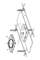
【図1】本考案に係る長尺繊維強化プラスチック補強材の梱包開梱装置の一実施例の分解斜視図である。
【図2】図1の梱包開梱装置の(a)平面図、(b)断面図である。
【図3】本考案に係る長尺繊維強化プラスチック補強材の梱包開梱装置の他の実施例の分解斜視図である。
【図4】図3の梱包開梱装置の(a)平面図、(b)断面図である。
【図5】本考案に係る長尺繊維強化プラスチック補強材の梱包開梱装置の更に他の実施例の分解斜視図である。
【図6】図5の梱包開梱装置の(a)平面図、(b)断面図である。
【図7】本考案に係る長尺繊維強化プラスチック補強材の梱包開梱装置を用いた繊維強化プラスチック補強材の梱包方法を説明するための当該梱包装置の斜視図である。
【図8】本考案に係る長尺繊維強化プラスチック補強材の梱包開梱装置を用いた繊維強化プラスチック補強材の梱包方法を説明するための長尺繊維強化プラスチック補強材の梱包具の斜視図である。
【図9】本考案に係る長尺繊維強化プラスチック補強材の梱包具に長尺の繊維強化プラスチック補強材が梱包された梱包物の斜視図である。
【図10】本考案に係る長尺繊維強化プラスチック補強材の梱包開梱装置を用いた繊維強化プラスチック補強材の開梱方法を説明するための説明図である。
【図11】本考案に係る長尺繊維強化プラスチック補強材の梱包開梱装置を用いた繊維強化プラスチック補強材の開梱方法を説明するための説明図である。
【図12】本考案に係る長尺繊維強化プラスチック補強材の梱包具に長尺の繊維強化プラスチック補強材が梱包された梱包物の輸送態様の一例を示す模式図である。
【図13】繊維強化プラスチック緊張工法を説明するための模式図である。
【図14】長尺の繊維強化プラスチック補強材の従来の輸送態様を示す模式図である。
【符号の説明】
1 梱包具(パレット)
2 ターンテーブル
20 上側テーブル
30 下側テーブル
100 FRPプレート(長尺繊維強化プラスチック補強材)
101 定着体[0001]
[Technical field to which the invention belongs]
The present invention relates to a packing device and a packing unpacking device for a long fiber-reinforced plastic (FRP) reinforcing material such as a plate and a cable.
[0002]
[Prior art]
2. Description of the Related Art Conventionally, as a method for reinforcing a concrete structure, there is an FRP tensioning method in which an FRP plate or cable, which is a continuous fiber reinforcing material, is mounted on a surface of an existing or new structure by introducing a prestress (tensile force).
[0003]
FIG. 13 shows an example in which the bridge is reinforced by the FRP tensioning method. In this example, a mode is shown in which prestress (tension) is introduced into the long
[0004]
The long
[0005]
When transporting a long thing exceeding 5 m, for example, with such an
[0006]
[Problems to be solved by the invention]
However, when the reel is not used, the weight increase is small and the packing volume is small, but when the
[0007]
On the other hand, when the
[0008]
For this reason, conventionally, when it is difficult to wind, pack, unpack, and transport without damaging the
[0009]
However, this has a problem that the transportation cost is high, and the length of the
[0010]
Therefore, an object of the present invention is to make it possible to pack a long fiber-reinforced plastic reinforcing material in a small size, and to reduce the space required for unpacking work, and to place the long fiber-reinforced plastic reinforcing material at a desired position. An object of the present invention is to provide a packing device and a packing unpacking device for a long fiber reinforced plastic reinforcing material that can be easily extended.
[0011]
Another object of the present invention is to make it possible to reduce the weight and space of a long fiber-reinforced plastic reinforcing package, to reduce the storage and transportation costs of the package, and to improve the storage and transportation workability and efficiency. An object of the present invention is to provide a packing device and a packing unpacking device for a long fiber reinforced plastic reinforcing material which can be improved.
[0012]
Further, another object of the present invention is to provide a long fiber reinforced plastic reinforcing material having good workability without damage even when a fixing member is fixed to an end of the long fiber reinforced plastic reinforcing material. It is an object of the present invention to provide a packing device and a packing and unpacking device for a long fiber reinforced plastic reinforcing material capable of packing and unpacking.
[0013]
[Means for Solving the Problems]
The above object is achieved by a packing device and a packing unpacking device for a long fiber reinforced plastic reinforcing material according to the present invention. In summary, the present invention holds a roll of long fiber reinforced plastic reinforcement on it, which is rotated on a turntable to pull out the long fiber reinforced plastic reinforcement from above. What is claimed is: 1. A packaging device for a long fiber reinforced plastic reinforcing material, characterized in that the packing device has a surface on which a side surface of the wound long fiber reinforced plastic reinforcing material is placed.
[0014]
According to one embodiment of the present invention, the long fiber reinforced plastic reinforcement packing device is rotated on a turntable, and the long fiber reinforced plastic reinforcement is wound thereon.
[0015]
According to one embodiment of the present invention, the packaging material of the long fiber-reinforced plastic reinforcement further faces the rotation center of the turntable or the turntable-side positioning means provided at a predetermined relative position with respect to the rotation center. The package has positioning means at the position. In one embodiment, the package-side positioning means is provided at a position adapted to the turntable-side positioning means to align the center of the package with the rotation center of the turntable. In one embodiment, the turntable-side positioning means is a shaft protruding from the center of rotation of the turntable, and the packing-side positioning means is provided at the center of the packing tool and a through hole for passing the shaft. This is a recess for accommodating the shaft. In another embodiment, the turntable-side positioning means is a protrusion disposed at a predetermined relative position with respect to the rotation center of the turntable, and the packing-piece-side positioning means is located at a position opposed to the turntable-side positioning means. The projections are arranged on the projections. In another embodiment, the turntable-side positioning means is a protrusion disposed at a predetermined relative position with respect to the rotation center of the turntable, and the packing-piece-side positioning means is located at a position opposed to the turntable-side positioning means. Is a through-hole or a concave portion disposed in the first hole. In still another embodiment, the turntable-side positioning means is a through-hole or a concave portion disposed at a predetermined relative position with respect to the rotation center of the turntable, and the packaging-piece-side positioning means is the turntable-side positioning means. And projections arranged at positions opposite to the above.
[0016]
According to one embodiment of the present invention, the packing device for the long fiber-reinforced plastic reinforcement further includes fixing means for fixing at least one end of the long fiber-reinforced plastic wound on the packing device. Have. In one embodiment, the fixing means is a fixing portion provided at an end of the long fiber-reinforced plastic reinforcing member, into which a fixing member is fitted. Further, according to one embodiment of the present invention, there is provided a separating member that separates the turntable from the turntable at least at a position of the fixing portion of the turnkey.
[0017]
In the present invention, the packaging of the long fiber reinforced plastic reinforcement can be made of laminated paper, wood, metal, fiber reinforced plastic or plastic.
[0018]
According to another aspect of the present invention, there is provided the packing device for the long fiber-reinforced plastic reinforcing material of the present invention, and a turntable that can rotate while carrying the packing device for the long fiber-reinforced plastic reinforcing material. An apparatus for packing and unpacking a long fiber reinforced plastic reinforcing material is provided.
[0019]
[Embodiment of the invention]
Hereinafter, a packing device and a packing unpacking device for a long fiber reinforced plastic reinforcing material according to the present invention will be described in more detail with reference to the drawings.
[0020]
Example 1
First, with reference to FIG. 1 and FIG. 2, one embodiment of a packing tool and a packing unpacking device according to the present invention will be described.
[0021]
In this embodiment, the packing and unpacking device A is used for unpacking and packing the
[0022]
According to the present invention, the
[0023]
The upper table 20 of the
[0024]
Here, as described above, the
[0025]
As the reinforcing fibers of the
[0026]
In the present embodiment, the
[0027]
Hereinafter, the packing and unpacking device A will be described in more detail.
[0028]
In the present embodiment, the
[0029]
As a material for forming the
[0030]
The size of the
[0031]
The shape of the
[0032]
The
[0033]
In the present embodiment, the lower table 30 includes a lower table
[0034]
As the material forming the upper table
[0035]
The size of the upper table 20 can be appropriately set so that the
[0036]
The size of the lower table 30 is set so that the
[0037]
The
[0038]
As in the case of the
[0039]
Here, according to a preferred aspect of the present invention, the
[0040]
In this embodiment, the rotating
[0041]
In the present embodiment, the
[0042]
In this way, by providing the package-side positioning means and the turntable-side positioning means on the
[0043]
Preferably, furthermore, a fixing means for fixing at least one end (for example, the end on the winding end side) of the
[0044]
A specific example of the packing and unpacking device A of the present embodiment is as follows.
・
Material: cardboard
Width W1a: 1.5m
Width W1b: 1.5m
Thickness T1: 5mm (weight about 2kg)
Inner diameter of pallet through hole D1: 55 mm
・ Upper table 20
Material of main body 21: wood (plywood)
Width W2a: 1m
Width W2b: 1m
Thickness T2: 12mm (weight about 6kg)
Inner diameter of upper table through-hole D2: 55 mm
Running radius R of wheels 22: 0.9 m
・ Lower table 30
Material of main body 21: wood (plywood)
Width W3a: 1m
Width W3b: 1m
Thickness T3: 12mm (weight 6kg)
Material of rotating shaft 32: wood
Outer diameter D3 of rotating shaft 32: 50 mm
Height H3 of rotary shaft 32: 150 mm
[0045]
As described above, according to the packing and unpacking apparatus A of the present embodiment, the
[0046]
Example 2
Next, another embodiment of the packing and unpacking device according to the present invention will be described with reference to FIGS. 3 and 4. The basic configuration of the packing and unpacking device of the present embodiment is the same as that of the first embodiment, and the packaging device side positioning means and the turntable side positioning means are different. Accordingly, elements having the same or equivalent functions and configurations as those of the packing and unpacking apparatus of the first embodiment are denoted by the same reference numerals, and detailed description thereof will be omitted.
[0047]
As shown in FIGS. 3 and 4, in the packing and unpacking device A for the
[0048]
In this embodiment, the turntable-side positioning means has a turntable-
[0049]
On the other hand, the
[0050]
The pallet-
[0051]
Thus, similarly to the first embodiment, the
[0052]
The
[0053]
Note that the positioning means on the package side and the positioning means on the turntable side are not limited to a mode in which the projections are adapted to each other. Either may be a through hole or a recess, and the other may be a protrusion. The relative position of the turntable-side positioning means with respect to the center of rotation of the
[0054]
As described above, according to the configuration of the present embodiment, similarly to the first embodiment, the
[0055]
Example 3
Next, another embodiment of the packing and unpacking device according to the present invention will be described with reference to FIGS. The basic configuration of the packing and unpacking device of this embodiment is the same as that described in
[0056]
In this embodiment, fixing
[0057]
Therefore, when there is a protrusion such as the fixing
[0058]
If the protrusion amount p of the fixing
[0059]
Although not limited thereto, in the illustrated example, the
[0060]
In addition, the separating
[0061]
In the present embodiment, each of the upper table 20 and the lower table 30 includes a
[0062]
In the present embodiment, as a turntable-side positioning means, a
[0063]
On the other hand, the pallet
[0064]
The
[0065]
As in the first embodiment, the
[0066]
As described above, according to the packing and unpacking device A of the present embodiment, the same effects as those of the above embodiments can be obtained, and even when the
[0067]
Example 4
Next, a method for packing and unpacking the
[0068]
In this embodiment, the fixing
[0069]
As shown in FIG. 7, when packing the
[0070]
Next, the fixing
[0071]
After winding up to the other end of the
[0072]
The
[0073]
Then, as shown in FIG. 9, the
[0074]
FIG. 12 shows a state in which a plurality of FRP plate packages 200 are stacked on a truck bed C and transported. According to the present invention, as compared with the conventional method of loading and transporting the
[0075]
On the other hand, for example, when the
[0076]
Then, the
[0077]
Next, as shown in FIG. 11, the fixing
[0078]
As described above, by using the packing and unpacking device A according to the present invention, the
[0079]
[Effect of the invention]
As described above, according to the present invention, a long fiber-reinforced plastic reinforcing material can be packed in a small size, and the space required for unpacking work can be reduced, and the long fiber-reinforced plastic reinforcement can be placed at a desired position. The plastic reinforcement can be easily extended. Further, according to the present invention, it is possible to reduce the weight and space of a long fiber-reinforced plastic reinforcing package, to reduce the storage and transportation costs of the package, and to improve the storage and transportation workability and efficiency. Improvement can be achieved. Furthermore, according to the present invention, even when the fixing member is fixed to the end of the long fiber-reinforced plastic reinforcing material, the long fiber-reinforced plastic reinforcing material is packed with good workability without damage. , Can be unpacked.
[Brief description of the drawings]
FIG. 1 is an exploded perspective view of one embodiment of a device for unpacking and packing a long fiber reinforced plastic reinforcing material according to the present invention.
2A is a plan view and FIG. 2B is a cross-sectional view of the packing and unpacking apparatus of FIG.
FIG. 3 is an exploded perspective view of another embodiment of the apparatus for packing and unpacking long fiber reinforced plastic reinforcement according to the present invention.
4A is a plan view and FIG. 3B is a cross-sectional view of the packing and unpacking apparatus of FIG.
FIG. 5 is an exploded perspective view of still another embodiment of the device for packing and unpacking long fiber reinforced plastic reinforcement according to the present invention.
6A is a plan view and FIG. 5B is a cross-sectional view of the packing and unpacking apparatus of FIG.
FIG. 7 is a perspective view of the packing device for explaining a packing method of the fiber-reinforced plastic reinforcing material using the packing and unpacking device for the long fiber-reinforced plastic reinforcing material according to the present invention.
FIG. 8 is a perspective view of a long fiber reinforced plastic reinforcing material packing tool for explaining a method of packing the fiber reinforced plastic reinforcing material using the packing and unpacking device for a long fiber reinforced plastic reinforcing material according to the present invention. is there.
FIG. 9 is a perspective view of a package in which a long fiber-reinforced plastic reinforcing material is packed in a long fiber-reinforced plastic reinforcing material packing device according to the present invention.
FIG. 10 is an explanatory view for explaining a method of unpacking the fiber-reinforced plastic reinforcement using the device for packing and unpacking the long fiber-reinforced plastic reinforcement according to the present invention.
FIG. 11 is an explanatory view illustrating a method of unpacking the fiber-reinforced plastic reinforcement using the device for packing and unpacking the long fiber-reinforced plastic reinforcement according to the present invention.
FIG. 12 is a schematic diagram showing an example of a transport mode of a package in which a long fiber-reinforced plastic reinforcing material is packed in a long fiber-reinforced plastic reinforcing material packing device according to the present invention.
FIG. 13 is a schematic diagram for explaining a fiber-reinforced plastic tensioning method.
FIG. 14 is a schematic diagram showing a conventional transport mode of a long fiber-reinforced plastic reinforcing material.
[Explanation of symbols]
1 packing materials (pallets)
2 Turntable
20 Upper table
30 lower table
100 FRP plate (long fiber reinforced plastic reinforcement)
101 fixing body
Claims (13)
Priority Applications (1)
| Application Number | Priority Date | Filing Date | Title |
|---|---|---|---|
| JP2003004084U JP3099175U (en) | 2003-07-11 | 2003-07-11 | Packing and unpacking equipment for long fiber reinforced plastic reinforcement |
Applications Claiming Priority (1)
| Application Number | Priority Date | Filing Date | Title |
|---|---|---|---|
| JP2003004084U JP3099175U (en) | 2003-07-11 | 2003-07-11 | Packing and unpacking equipment for long fiber reinforced plastic reinforcement |
Publications (1)
| Publication Number | Publication Date |
|---|---|
| JP3099175U true JP3099175U (en) | 2004-03-25 |
Family
ID=43252896
Family Applications (1)
| Application Number | Title | Priority Date | Filing Date |
|---|---|---|---|
| JP2003004084U Expired - Lifetime JP3099175U (en) | 2003-07-11 | 2003-07-11 | Packing and unpacking equipment for long fiber reinforced plastic reinforcement |
Country Status (1)
| Country | Link |
|---|---|
| JP (1) | JP3099175U (en) |
-
2003
- 2003-07-11 JP JP2003004084U patent/JP3099175U/en not_active Expired - Lifetime
Similar Documents
| Publication | Publication Date | Title |
|---|---|---|
| EP0525093B1 (en) | A method of manufacturing a coil of a continuous flexible object and enveloping the coil to form a parcel | |
| US5826721A (en) | Rolled article storing and transporting container | |
| JP5255815B2 (en) | Pail pack for welding wire | |
| US5735482A (en) | Apparatus and method for winding, transporting, and unwinding conveyor belts | |
| JP7015157B2 (en) | Assembled pedestal, manufacturing method of assembled pedestal, transportation method by container, and sea transportation method by container | |
| JP5982448B2 (en) | Balloon mooring device, balloon carrier device and balloon mooring ship | |
| JP4371969B2 (en) | Method for forming strip plate bundle and method for unrolling strip plate bundle | |
| JP3099175U (en) | Packing and unpacking equipment for long fiber reinforced plastic reinforcement | |
| KR100297164B1 (en) | Apparatus for welding wire acceptance | |
| JP3370911B2 (en) | Integrated body of LP insulator and method of integrating the same | |
| JP3704574B2 (en) | Wire box | |
| JP2002337923A (en) | Architectural composite panel conveying device | |
| CN110550296B (en) | Fork plate frame | |
| JPH01209284A (en) | Cable handling device | |
| WO1994025361A1 (en) | Apparatus for transportation of stacks of lumber | |
| JP4181726B2 (en) | Roll product shipping container | |
| US20240409359A1 (en) | Reel Made from Separable Components | |
| JPS6211775Y2 (en) | ||
| CN212076180U (en) | Novel building electrical construction goes up and down device | |
| JP3308199B2 (en) | Cable drum | |
| JP2002104728A (en) | Transporter for coiled and bundled electric wire | |
| CN118637189A (en) | Coil material transport storage device and use method | |
| JPS6034693Y2 (en) | Drum pallet for short cables | |
| JPH08214430A (en) | Device for paying out rope for stringing transmission line | |
| PT101057A (en) | Process for manufacturing a reel of a continuous flexible article, system for handling the continuous flexible article and tool for application in the process |
Legal Events
| Date | Code | Title | Description |
|---|---|---|---|
| FPAY | Renewal fee payment (event date is renewal date of database) |
Free format text: PAYMENT UNTIL: 20081029 Year of fee payment: 5 |
|
| FPAY | Renewal fee payment (event date is renewal date of database) |
Free format text: PAYMENT UNTIL: 20081029 Year of fee payment: 5 |
|
| FPAY | Renewal fee payment (event date is renewal date of database) |
Free format text: PAYMENT UNTIL: 20091029 Year of fee payment: 6 |
|
| EXPY | Cancellation because of completion of term | ||
| FPAY | Renewal fee payment (event date is renewal date of database) |
Free format text: PAYMENT UNTIL: 20091029 Year of fee payment: 6 |