JP2022168126A - catheter assembly - Google Patents
catheter assembly Download PDFInfo
- Publication number
- JP2022168126A JP2022168126A JP2022143044A JP2022143044A JP2022168126A JP 2022168126 A JP2022168126 A JP 2022168126A JP 2022143044 A JP2022143044 A JP 2022143044A JP 2022143044 A JP2022143044 A JP 2022143044A JP 2022168126 A JP2022168126 A JP 2022168126A
- Authority
- JP
- Japan
- Prior art keywords
- needle
- catheter
- catheter hub
- clip
- hub
- Prior art date
- Legal status (The legal status is an assumption and is not a legal conclusion. Google has not performed a legal analysis and makes no representation as to the accuracy of the status listed.)
- Pending
Links
Images


Classifications
-
- A—HUMAN NECESSITIES
- A61—MEDICAL OR VETERINARY SCIENCE; HYGIENE
- A61M—DEVICES FOR INTRODUCING MEDIA INTO, OR ONTO, THE BODY; DEVICES FOR TRANSDUCING BODY MEDIA OR FOR TAKING MEDIA FROM THE BODY; DEVICES FOR PRODUCING OR ENDING SLEEP OR STUPOR
- A61M25/00—Catheters; Hollow probes
- A61M25/01—Introducing, guiding, advancing, emplacing or holding catheters
- A61M25/06—Body-piercing guide needles or the like
- A61M25/0612—Devices for protecting the needle; Devices to help insertion of the needle, e.g. wings or holders
- A61M25/0618—Devices for protecting the needle; Devices to help insertion of the needle, e.g. wings or holders having means for protecting only the distal tip of the needle, e.g. a needle guard
-
- A—HUMAN NECESSITIES
- A61—MEDICAL OR VETERINARY SCIENCE; HYGIENE
- A61M—DEVICES FOR INTRODUCING MEDIA INTO, OR ONTO, THE BODY; DEVICES FOR TRANSDUCING BODY MEDIA OR FOR TAKING MEDIA FROM THE BODY; DEVICES FOR PRODUCING OR ENDING SLEEP OR STUPOR
- A61M25/00—Catheters; Hollow probes
- A61M25/0067—Catheters; Hollow probes characterised by the distal end, e.g. tips
- A61M25/0074—Dynamic characteristics of the catheter tip, e.g. openable, closable, expandable or deformable
- A61M25/0075—Valve means
-
- A—HUMAN NECESSITIES
- A61—MEDICAL OR VETERINARY SCIENCE; HYGIENE
- A61M—DEVICES FOR INTRODUCING MEDIA INTO, OR ONTO, THE BODY; DEVICES FOR TRANSDUCING BODY MEDIA OR FOR TAKING MEDIA FROM THE BODY; DEVICES FOR PRODUCING OR ENDING SLEEP OR STUPOR
- A61M25/00—Catheters; Hollow probes
- A61M25/0097—Catheters; Hollow probes characterised by the hub
-
- A—HUMAN NECESSITIES
- A61—MEDICAL OR VETERINARY SCIENCE; HYGIENE
- A61M—DEVICES FOR INTRODUCING MEDIA INTO, OR ONTO, THE BODY; DEVICES FOR TRANSDUCING BODY MEDIA OR FOR TAKING MEDIA FROM THE BODY; DEVICES FOR PRODUCING OR ENDING SLEEP OR STUPOR
- A61M25/00—Catheters; Hollow probes
- A61M25/01—Introducing, guiding, advancing, emplacing or holding catheters
- A61M25/06—Body-piercing guide needles or the like
- A61M25/0606—"Over-the-needle" catheter assemblies, e.g. I.V. catheters
-
- A—HUMAN NECESSITIES
- A61—MEDICAL OR VETERINARY SCIENCE; HYGIENE
- A61M—DEVICES FOR INTRODUCING MEDIA INTO, OR ONTO, THE BODY; DEVICES FOR TRANSDUCING BODY MEDIA OR FOR TAKING MEDIA FROM THE BODY; DEVICES FOR PRODUCING OR ENDING SLEEP OR STUPOR
- A61M25/00—Catheters; Hollow probes
- A61M25/01—Introducing, guiding, advancing, emplacing or holding catheters
- A61M25/06—Body-piercing guide needles or the like
- A61M25/0612—Devices for protecting the needle; Devices to help insertion of the needle, e.g. wings or holders
- A61M25/0631—Devices for protecting the needle; Devices to help insertion of the needle, e.g. wings or holders having means for fully covering the needle after its withdrawal, e.g. needle being withdrawn inside the handle or a cover being advanced over the needle
-
- A—HUMAN NECESSITIES
- A61—MEDICAL OR VETERINARY SCIENCE; HYGIENE
- A61M—DEVICES FOR INTRODUCING MEDIA INTO, OR ONTO, THE BODY; DEVICES FOR TRANSDUCING BODY MEDIA OR FOR TAKING MEDIA FROM THE BODY; DEVICES FOR PRODUCING OR ENDING SLEEP OR STUPOR
- A61M39/00—Tubes, tube connectors, tube couplings, valves, access sites or the like, specially adapted for medical use
- A61M39/02—Access sites
- A61M39/06—Haemostasis valves, i.e. gaskets sealing around a needle, catheter or the like, closing on removal thereof
- A61M39/0693—Haemostasis valves, i.e. gaskets sealing around a needle, catheter or the like, closing on removal thereof including means for seal penetration
-
- A—HUMAN NECESSITIES
- A61—MEDICAL OR VETERINARY SCIENCE; HYGIENE
- A61M—DEVICES FOR INTRODUCING MEDIA INTO, OR ONTO, THE BODY; DEVICES FOR TRANSDUCING BODY MEDIA OR FOR TAKING MEDIA FROM THE BODY; DEVICES FOR PRODUCING OR ENDING SLEEP OR STUPOR
- A61M39/00—Tubes, tube connectors, tube couplings, valves, access sites or the like, specially adapted for medical use
- A61M39/22—Valves or arrangement of valves
- A61M39/24—Check- or non-return valves
-
- A—HUMAN NECESSITIES
- A61—MEDICAL OR VETERINARY SCIENCE; HYGIENE
- A61M—DEVICES FOR INTRODUCING MEDIA INTO, OR ONTO, THE BODY; DEVICES FOR TRANSDUCING BODY MEDIA OR FOR TAKING MEDIA FROM THE BODY; DEVICES FOR PRODUCING OR ENDING SLEEP OR STUPOR
- A61M5/00—Devices for bringing media into the body in a subcutaneous, intra-vascular or intramuscular way; Accessories therefor, e.g. filling or cleaning devices, arm-rests
- A61M5/14—Infusion devices, e.g. infusing by gravity; Blood infusion; Accessories therefor
- A61M5/158—Needles for infusions; Accessories therefor, e.g. for inserting infusion needles, or for holding them on the body
-
- A—HUMAN NECESSITIES
- A61—MEDICAL OR VETERINARY SCIENCE; HYGIENE
- A61M—DEVICES FOR INTRODUCING MEDIA INTO, OR ONTO, THE BODY; DEVICES FOR TRANSDUCING BODY MEDIA OR FOR TAKING MEDIA FROM THE BODY; DEVICES FOR PRODUCING OR ENDING SLEEP OR STUPOR
- A61M5/00—Devices for bringing media into the body in a subcutaneous, intra-vascular or intramuscular way; Accessories therefor, e.g. filling or cleaning devices, arm-rests
- A61M5/178—Syringes
- A61M5/31—Details
- A61M5/32—Needles; Details of needles pertaining to their connection with syringe or hub; Accessories for bringing the needle into, or holding the needle on, the body; Devices for protection of needles
- A61M5/3202—Devices for protection of the needle before use, e.g. caps
-
- A—HUMAN NECESSITIES
- A61—MEDICAL OR VETERINARY SCIENCE; HYGIENE
- A61M—DEVICES FOR INTRODUCING MEDIA INTO, OR ONTO, THE BODY; DEVICES FOR TRANSDUCING BODY MEDIA OR FOR TAKING MEDIA FROM THE BODY; DEVICES FOR PRODUCING OR ENDING SLEEP OR STUPOR
- A61M5/00—Devices for bringing media into the body in a subcutaneous, intra-vascular or intramuscular way; Accessories therefor, e.g. filling or cleaning devices, arm-rests
- A61M5/178—Syringes
- A61M5/31—Details
- A61M5/32—Needles; Details of needles pertaining to their connection with syringe or hub; Accessories for bringing the needle into, or holding the needle on, the body; Devices for protection of needles
- A61M5/3205—Apparatus for removing or disposing of used needles or syringes, e.g. containers; Means for protection against accidental injuries from used needles
- A61M5/321—Means for protection against accidental injuries by used needles
- A61M5/3213—Caps placed axially onto the needle, e.g. equipped with finger protection guards
-
- A—HUMAN NECESSITIES
- A61—MEDICAL OR VETERINARY SCIENCE; HYGIENE
- A61M—DEVICES FOR INTRODUCING MEDIA INTO, OR ONTO, THE BODY; DEVICES FOR TRANSDUCING BODY MEDIA OR FOR TAKING MEDIA FROM THE BODY; DEVICES FOR PRODUCING OR ENDING SLEEP OR STUPOR
- A61M5/00—Devices for bringing media into the body in a subcutaneous, intra-vascular or intramuscular way; Accessories therefor, e.g. filling or cleaning devices, arm-rests
- A61M5/178—Syringes
- A61M5/31—Details
- A61M5/32—Needles; Details of needles pertaining to their connection with syringe or hub; Accessories for bringing the needle into, or holding the needle on, the body; Devices for protection of needles
- A61M5/3205—Apparatus for removing or disposing of used needles or syringes, e.g. containers; Means for protection against accidental injuries from used needles
- A61M5/321—Means for protection against accidental injuries by used needles
- A61M5/322—Retractable needles, i.e. disconnected from and withdrawn into the syringe barrel by the piston
- A61M5/3232—Semi-automatic needle retraction, i.e. in which triggering of the needle retraction requires a deliberate action by the user, e.g. manual release of spring-biased retraction means
-
- A—HUMAN NECESSITIES
- A61—MEDICAL OR VETERINARY SCIENCE; HYGIENE
- A61M—DEVICES FOR INTRODUCING MEDIA INTO, OR ONTO, THE BODY; DEVICES FOR TRANSDUCING BODY MEDIA OR FOR TAKING MEDIA FROM THE BODY; DEVICES FOR PRODUCING OR ENDING SLEEP OR STUPOR
- A61M5/00—Devices for bringing media into the body in a subcutaneous, intra-vascular or intramuscular way; Accessories therefor, e.g. filling or cleaning devices, arm-rests
- A61M5/178—Syringes
- A61M5/31—Details
- A61M5/32—Needles; Details of needles pertaining to their connection with syringe or hub; Accessories for bringing the needle into, or holding the needle on, the body; Devices for protection of needles
- A61M5/34—Constructions for connecting the needle, e.g. to syringe nozzle or needle hub
-
- A—HUMAN NECESSITIES
- A61—MEDICAL OR VETERINARY SCIENCE; HYGIENE
- A61M—DEVICES FOR INTRODUCING MEDIA INTO, OR ONTO, THE BODY; DEVICES FOR TRANSDUCING BODY MEDIA OR FOR TAKING MEDIA FROM THE BODY; DEVICES FOR PRODUCING OR ENDING SLEEP OR STUPOR
- A61M39/00—Tubes, tube connectors, tube couplings, valves, access sites or the like, specially adapted for medical use
- A61M39/02—Access sites
- A61M39/06—Haemostasis valves, i.e. gaskets sealing around a needle, catheter or the like, closing on removal thereof
- A61M2039/062—Haemostasis valves, i.e. gaskets sealing around a needle, catheter or the like, closing on removal thereof used with a catheter
-
- A—HUMAN NECESSITIES
- A61—MEDICAL OR VETERINARY SCIENCE; HYGIENE
- A61M—DEVICES FOR INTRODUCING MEDIA INTO, OR ONTO, THE BODY; DEVICES FOR TRANSDUCING BODY MEDIA OR FOR TAKING MEDIA FROM THE BODY; DEVICES FOR PRODUCING OR ENDING SLEEP OR STUPOR
- A61M39/00—Tubes, tube connectors, tube couplings, valves, access sites or the like, specially adapted for medical use
- A61M39/02—Access sites
- A61M39/06—Haemostasis valves, i.e. gaskets sealing around a needle, catheter or the like, closing on removal thereof
- A61M2039/0633—Haemostasis valves, i.e. gaskets sealing around a needle, catheter or the like, closing on removal thereof the seal being a passive seal made of a resilient material with or without an opening
- A61M2039/064—Slit-valve
-
- A—HUMAN NECESSITIES
- A61—MEDICAL OR VETERINARY SCIENCE; HYGIENE
- A61M—DEVICES FOR INTRODUCING MEDIA INTO, OR ONTO, THE BODY; DEVICES FOR TRANSDUCING BODY MEDIA OR FOR TAKING MEDIA FROM THE BODY; DEVICES FOR PRODUCING OR ENDING SLEEP OR STUPOR
- A61M39/00—Tubes, tube connectors, tube couplings, valves, access sites or the like, specially adapted for medical use
- A61M39/02—Access sites
- A61M39/06—Haemostasis valves, i.e. gaskets sealing around a needle, catheter or the like, closing on removal thereof
- A61M2039/0633—Haemostasis valves, i.e. gaskets sealing around a needle, catheter or the like, closing on removal thereof the seal being a passive seal made of a resilient material with or without an opening
- A61M2039/066—Septum-like element
-
- A—HUMAN NECESSITIES
- A61—MEDICAL OR VETERINARY SCIENCE; HYGIENE
- A61M—DEVICES FOR INTRODUCING MEDIA INTO, OR ONTO, THE BODY; DEVICES FOR TRANSDUCING BODY MEDIA OR FOR TAKING MEDIA FROM THE BODY; DEVICES FOR PRODUCING OR ENDING SLEEP OR STUPOR
- A61M39/00—Tubes, tube connectors, tube couplings, valves, access sites or the like, specially adapted for medical use
- A61M39/02—Access sites
- A61M39/06—Haemostasis valves, i.e. gaskets sealing around a needle, catheter or the like, closing on removal thereof
- A61M2039/0673—Haemostasis valves, i.e. gaskets sealing around a needle, catheter or the like, closing on removal thereof comprising means actively pressing on the device passing through the seal, e.g. inflatable seals, diaphragms, clamps
-
- A—HUMAN NECESSITIES
- A61—MEDICAL OR VETERINARY SCIENCE; HYGIENE
- A61M—DEVICES FOR INTRODUCING MEDIA INTO, OR ONTO, THE BODY; DEVICES FOR TRANSDUCING BODY MEDIA OR FOR TAKING MEDIA FROM THE BODY; DEVICES FOR PRODUCING OR ENDING SLEEP OR STUPOR
- A61M39/00—Tubes, tube connectors, tube couplings, valves, access sites or the like, specially adapted for medical use
- A61M39/22—Valves or arrangement of valves
- A61M2039/226—Spindles or actuating means
-
- A—HUMAN NECESSITIES
- A61—MEDICAL OR VETERINARY SCIENCE; HYGIENE
- A61M—DEVICES FOR INTRODUCING MEDIA INTO, OR ONTO, THE BODY; DEVICES FOR TRANSDUCING BODY MEDIA OR FOR TAKING MEDIA FROM THE BODY; DEVICES FOR PRODUCING OR ENDING SLEEP OR STUPOR
- A61M5/00—Devices for bringing media into the body in a subcutaneous, intra-vascular or intramuscular way; Accessories therefor, e.g. filling or cleaning devices, arm-rests
- A61M5/178—Syringes
- A61M5/31—Details
- A61M5/32—Needles; Details of needles pertaining to their connection with syringe or hub; Accessories for bringing the needle into, or holding the needle on, the body; Devices for protection of needles
- A61M5/3205—Apparatus for removing or disposing of used needles or syringes, e.g. containers; Means for protection against accidental injuries from used needles
- A61M5/321—Means for protection against accidental injuries by used needles
- A61M5/3243—Means for protection against accidental injuries by used needles being axially-extensible, e.g. protective sleeves coaxially slidable on the syringe barrel
- A61M5/3273—Means for protection against accidental injuries by used needles being axially-extensible, e.g. protective sleeves coaxially slidable on the syringe barrel freely sliding on needle shaft without connection to syringe or needle
Landscapes
- Health & Medical Sciences (AREA)
- Life Sciences & Earth Sciences (AREA)
- Engineering & Computer Science (AREA)
- Heart & Thoracic Surgery (AREA)
- Hematology (AREA)
- Veterinary Medicine (AREA)
- Biomedical Technology (AREA)
- Anesthesiology (AREA)
- Animal Behavior & Ethology (AREA)
- General Health & Medical Sciences (AREA)
- Public Health (AREA)
- Pulmonology (AREA)
- Biophysics (AREA)
- Vascular Medicine (AREA)
- Environmental & Geological Engineering (AREA)
- Infusion, Injection, And Reservoir Apparatuses (AREA)
- Media Introduction/Drainage Providing Device (AREA)
- Materials For Medical Uses (AREA)
Abstract
Description
関連出願
本出願は、2014年4月18日出願の米国仮特許出願第61/981223号、2014年4月18日出願の米国仮特許出願第61/981312号、および、2014年11月10日出願の米国仮特許出願第62/077760の35 U.S.C.§119(e)に基づく利益を主張する。これら出願のそれぞれは、その全体が参照により本明細書に組み込まれる。
分野
本発明の様々な例示的実施形態はカテーテルに関する。
RELATED APPLICATIONS This application is filed April 18, 2014, U.S. Provisional Application No. 61/981,223; U.S. Provisional Application No. 61/981,312, filed April 18, 2014; 35 U.S.C. of filed US Provisional Patent Application No. 62/077760. S. C. Claim benefits under §119(e). Each of these applications is incorporated herein by reference in its entirety.
FIELD Various exemplary embodiments of the present invention relate to catheters.
カテーテルを患者の血管系内に適切に配置するためにカテーテルアセンブリが使用されている。いったん所定の位置で、例えば、静脈内カテーテルなどのカテーテルを、生理食塩水、医薬化合物、および/または、栄養組成物を含む流体をそのような治療を必要とする患者に注入するために使用することができる。カテーテルは、さらに、循環系からの流体の除去および患者の血管系内の状態のモニタを可能にする。 Catheter assemblies are used to properly position a catheter within a patient's vasculature. Once in place, a catheter, such as an intravenous catheter, is used to infuse fluids containing saline, pharmaceutical compounds, and/or nutritional compositions into a patient in need of such treatment. be able to. Catheters also allow removal of fluids from the circulatory system and monitoring of conditions within the patient's vasculature.
クリップが針保護を提供するがカテーテルハブを針シールドに連結しないカテーテルアセンブリを提供することが本発明の一態様である。代わりに、カテーテルアセンブリは、外側針部材、内側針部材、および、該内側針部材内に配置されたクリップを内蔵する。外側部材は、内側部材における対向部材の係合であって、カテーテルハブのボアとの係合に基づいて、カテーテルハブを連結する。針保護装置は、既存のカテーテルハブと一緒に使用することができ、カテーテルハブの外部または内部に備えられるべきどのような特別な機能も必要としない。 It is an aspect of the present invention to provide a catheter assembly in which the clip provides needle protection but does not connect the catheter hub to the needle shield. Alternatively, the catheter assembly incorporates an outer needle member, an inner needle member, and a clip disposed within the inner needle member. The outer member couples the catheter hub based on engagement of the opposing member on the inner member with the bore of the catheter hub. The needle protector can be used with existing catheter hubs and does not require any special features to be provided externally or internally to the catheter hub.
本発明の前述のおよび/または他の態様は、可撓性のカテーテル、カテーテルハブ、尖った遠位先端部を有する針であって、前記可撓性のカテーテル内に配置され、および、該針を露出させる第1の位置から第2の位置に移動する針、前記カテーテルハブと係合しおよび係合解除するように構成された外側部材であって、前記針が前記第1の位置にあるときに前記カテーテルハブの外面に係合する外側部材、前記外側部材内に移動可能に配置された内側部材であって、この内側部材は対向部材を含み、および、前記対向部材は前記針が前記第1の位置にあるときに前記カテーテルハブの内面内に延在している内側部材、および、前記内側部材内に配置された針保護部材であって、前記針が前記第2の位置にあるときに前記針の少なくとも一部を囲む針保護部材を備え、前記針が前記第2の位置に移動されるときに、前記内側部材は前記外側部材に対して軸方向に移動し、これにより、前記対向部材が前記カテーテルハブから取り外され、および、前記外側部材が前記カテーテルハブから外れることが可能とされるカテーテルアセンブリを提供することによって達成することができる。 The foregoing and/or other aspects of the invention provide a flexible catheter, a catheter hub, a needle having a sharpened distal tip, disposed within the flexible catheter, and an outer member configured to engage and disengage with said catheter hub, said needle being in said first position; an outer member sometimes engaging an outer surface of the catheter hub; an inner member movably disposed within the outer member, the inner member including an opposing member; an inner member extending within an inner surface of the catheter hub when in the first position; and a needle protection member disposed within the inner member, the needle being in the second position. sometimes comprising a needle protection member surrounding at least a portion of the needle, wherein the inner member axially moves relative to the outer member when the needle is moved to the second position, whereby This can be accomplished by providing a catheter assembly in which the opposing member is detached from the catheter hub and the outer member is allowed to be disengaged from the catheter hub.
本発明の前述のおよび/または他の態様は、可撓性のカテーテル、尖った遠位先端部を有する針であって、前記可撓性のカテーテル内に配置され、および、該針を露出させる第1の位置から第2の位置に移動する針、カテーテルハブと係合しおよび係合解除するように構成された外側部材、前記外側部材内に配置された内側部材であって、前記針が前記第1の位置にあるときに前記カテーテルハブに係合する対向部材を有する内側部材、および、前記内側部材内に配置された針保護部材であって、前記針が前記第2の位置にあるときに前記針の少なくとも一部を囲む針保護部材を備えたカテーテルアセンブリであって、前記針が前記第2の位置にあるときに、前記内側部材が前記外側部材に対して軸方向に移動して、前記対向部材を前記カテーテルハブから外れさせ、および、前記外側部材が前記カテーテルハブから外れることを可能にするカテーテルアセンブリを提供することによって達成することができる。 The foregoing and/or other aspects of the invention provide a flexible catheter, a needle having a sharpened distal tip disposed within the flexible catheter and exposing the needle. a needle that moves from a first position to a second position; an outer member configured to engage and disengage with a catheter hub; an inner member disposed within the outer member, the needle comprising: an inner member having an opposing member that engages the catheter hub when in the first position; and a needle protection member disposed within the inner member, the needle being in the second position. A catheter assembly sometimes comprising a needle protection member surrounding at least a portion of said needle, wherein said inner member axially moves relative to said outer member when said needle is in said second position. by providing a catheter assembly that allows the opposing member to be disengaged from the catheter hub and the outer member to be disengaged from the catheter hub.
本発明の前述のおよび/または他の態様は、尖った遠位先端部を有する針を可撓性のカテーテル内および血液を受けるように設定された第1の位置に配置すること、血液の流れを維持したまま前記針を前記可撓性のカテーテルを通して退避させること、前記針の少なくとも一部を第2の位置において針保護部材によって囲むこと、前記第1の位置において内側部材はカテーテルハブ内に配置された対向部材を含み、前記第2の位置において前記針を後退させるときに、前記内側部材内に配置された前記針保護部材を移動させ、前記対向部材を前記カテーテルハブから取り外し、そのことが、前記内側部材を外側部材の内側で軸方向に移動させ、および、前記外側部材がカテーテルハブから外れることを可能にすることを含む、カテーテルアセンブリを動作させる方法を提供することによって達成することができる。 The foregoing and/or other aspects of the present invention involve positioning a needle having a sharpened distal tip within a flexible catheter and at a first location configured to receive blood, blood flow at least a portion of the needle is surrounded by a needle protection member in a second position; and the inner member is within the catheter hub in the first position. an opposing member positioned to move the needle protection member positioned within the inner member to disengage the opposing member from the catheter hub upon retraction of the needle in the second position; by providing a method of operating a catheter assembly comprising moving said inner member axially inside an outer member and allowing said outer member to disengage from a catheter hub. can be done.
本発明の追加のおよび/または他の態様および利点は、以下の説明に記載され、または以下の説明から明らかなように、本発明の実施によって知ることができる。 Additional and/or other aspects and advantages of the invention may be set forth in, or may be made apparent from, the following description by practice of the invention.
本発明の上記の態様および特徴は、ここで、添付図面を参照することで、本発明の例示的実施形態の説明からより明らかになろう。
カテーテル10は、図1~6に示すように、中空の金属製導入針12、カテーテルハブ14、針ハブ16、針カバー18、および、針シールド20を含む。針カバー18は、最初は、針12、および、カテーテルハブ14の少なくとも一部を覆っている。針カバー18は、カテーテルハブ14に、または針ハブ16に接続することができる。針12は、尖った遠位端を有し、および、最初は針シールド20およびカテーテルハブ14を通って延びている。可撓性カテーテルチューブ22は、導入針12がカテーテルチューブ22を通過すると、カテーテルハブ14の遠位端から延在する。最初は、針12は露出されており(例えば、第1の位置)、そして、患者の静脈に挿入される。カテーテルチューブ22は、針12に沿って、針12に続いて静脈内に押し込まれる。カテーテルチューブ22が挿入された後、針12は、患者の静脈およびカテーテルハブ14から取り除かれる。針シールド20は、針12の尖った遠位側の先端を囲み、および、カテーテルハブ14からの針の退避中および退避後に、針12による突き刺しからの保護を提供する。針シールド20は、図2および図4に示すような標準的なカテーテルハブ14、および、図3および図5に示すようなサイドポートカテーテルハブ24を含む、様々な異なるカテーテルと共に使用することができる。
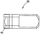
様々な例示的実施形態によれば、針シールド20は、外側部材26、内側部材28、弾性のあるクリップ30を含む。外側および内側部材26,28は、スリーブの形態であることが好ましい。外側スリーブ26は、カテーテルハブ14に接続し、および、内側スリーブ28およびクリップ30を囲んでいる。内側スリーブ28は、外側スリーブ26内に位置し、および、外側スリーブ26に対して相対的に軸方向に移動可能である。クリップ30は、内側スリーブ28に接続され、および、内側スリーブ28に対し軸方向に移動可能である。外側スリーブ26、内側スリーブ28、および、クリップ30を、金属、エラストマー、ポリマー、または複合材料から形成することができる。様々な例示的実施形態において、外側スリーブ26および内側スリーブ28はポリマー材料から成形され、および、クリップ30は、ステンレス鋼などの弾性金属の薄片から形成されている。開示されている様々な実施形態におけるクリップは、例示的な針保護材として作用することができる。図1~6の例示的実施形態の構造は、本明細書において開示される他の例示的実施形態の構造と必要に応じて組み合わせることができる。
According to various exemplary embodiments,
図7A~7Jに示された例示的実施形態に従えば、外側スリーブ26は、外面32、内面34、近位開口部36、および、遠位開口部38を含む。外面32は8つの平坦な側面を有する八角形の構成を有しているが、他の曲線および/または直線的形状を使用することもできる。内面34は、湾曲した一対の面によって接続された平坦な頂部壁および平坦な底部壁を有している。内面34は、内側スリーブ28を受けるためのキャビティを画定している。導入針12は、最初は近位の開口部および遠位の開口部を通って延びている。
スロット40は、外側スリーブ26の壁を通って延びている。外側スリーブの大きさ、形状、および構成は、スペース要件およびカテーテルハブ14の種類に応じて変えることができる。
According to the exemplary embodiment shown in FIGS. 7A-7J,
キャッチ部42は、図8A~8Bに最もよく示すように、カテーテルハブ14上の突出部44と係合または連結するように、外面から延在している。この係合は、針12がクリップ30で囲まれるより前に起きる。様々な例示的実施形態において、キャッチ部42を、溝、スロット、または孔を含む、カテーテルハブ14上のどのようなタイプの構造とも係合するように構成することができる。キャッチ部42の変形は、カテーテルハブ14の構成に依存することもある。例示的実施形態において、カテーテルハブ突出部44は、例えば、LUER-LOK(商標)型スレッドのスレッドを受けるルアーである。
キャッチ部42は、前縁、後縁、および、一対の側縁を有する。開口部すなわちくぼみが、前縁と後縁の間に、カテーテルハブ突出部44を受けるように形成されている。開口部は、突出部44の高さとほぼ等しいまたはわずかに大きい隙間を持ってキャッチ部42が形成されることを可能とし、必要な材料およびスペースの量を最小限にしながら、キャッチ部42がルアースレッドの突出部44の前、後、および/または、側面と係合することが可能になる。様々な例示的実施形態において、開口部を省略することができる。キャッチ部42は、カテーテルハブ14からの針シールド20の早期の解放に抵抗する。図7A~8Bの例示的実施形態の構造を、必要に応じて、本明細書に開示される他の例示的実施形態の構造と組み合わせることができる。
The
図9A~9Iに示された例示的実施形態に従えば、内側スリーブ28は、ベース46、遠位辺48、および、近位辺50を含む。弾性のある脚部52および足部54が、ベース46の外面から延びている。弾性のある脚部52および足部54は、外側スリーブ26におけるスロット40に係合する。1つまたはより多くのクリップリテーナ56が、ベース46の内面から延びている。クリップ30は、クリップリテーナ56と近位辺50の間に位置している。対向部材58が、遠位辺48から遠位方向に延びている。対向部材58は、針12が露出位置(例えば第1の位置)にあるときにカテーテルハブ14に挿入されるように構成されている。図9A~9Iに示す例示的実施形態において、対向部材は管状部材である。近位辺50、遠位辺48と対向部材58はそれぞれ、導入針12を受け入れるための開口部を有する。内側スリーブ28の大きさ、形状、および構成は、スペース要件およびカテーテルハブ14と外側スリーブ26の種類に応じて変えることができる。
According to the exemplary embodiment shown in FIGS. 9A-9I,
内側スリーブ18の代替実施形態において、ブリッジ部材(不図示)を組み込んで、内側スリーブ18の強度を向上させることができる。具体的には、遠位辺48の上面および近位辺50の上面を、ベース46と同様の長さを有する固体部材で接続してもよい。内側スリーブ18は、例えば、射出成形によって製造することができる。
In an alternative embodiment of
代替実施形態において、ベース46の足部54を取り除くことができ、および、ベース46を固体部材とすることができる。この構成によれば、内側スリーブ28は、適切な保持を達成するように外側スリーブ26内で変形する。内側スリーブ28および外側スリーブ26は、所定の力を加えた際に、内側スリーブ28が内側で軸方向におよび外側スリーブ26に対して移動することもできるように、適切な大きとされている。所定の力よりも小さい力が加えられた場合、内側スリーブ28は外側スリーブ26に対して移動しない。
このような構成は、内側スリーブ28および外側スリーブ26の成形性および生産性を向上させる。図9A~9Iの例示的実施形態の構造を、必要に応じて、本明細書に開示される他の例示的実施形態の構造と組み合わせることができる。
In alternate embodiments, the
Such a configuration improves moldability and manufacturability of
図10A~10Iに示された例示的実施形態に従えば、弾性のあるクリップ30は、針12を受けるための開口部を有するベース60と、第1のアーム62と、ベース60から延びるている第2のアーム64を含む。第1のアーム62は、第2のアーム64よりもさらに軸方向に延びている。第1のアーム62は第1のフック66を有し、第2のアーム64は第2のフック68を有する。第1のタブ70が第1のアーム62内に形成されており、第2のタブ72が第2のアーム64内に形成されている。図10A~10Iの例示的実施形態の構造を、適宜、本明細書に開示される他の例示的実施形態の構造と組み合わせることができる。
According to the exemplary embodiment shown in FIGS. 10A-10I,
図11および図12は、針シールド20の組み立てられた状態の例示的実施形態を示す。図11は、外側スリーブ26のスロット40内に位置する、脚部52および内側スリーブ28の足部54を示す。足部54がスロット40に係合して、内側スリーブ28の外側スリーブ26に対する軸方向の移動であって足部54がスロット40の端部と係合するポイントを通り過ぎる移動に抵抗する。脚部52および足部54はまた、内側スリーブ28上に形成されたスロット40と共に、外側スリーブ26上に形成することができる。図12は、外側スリーブ26上の第1の肩部74および第2の肩部76に係合している第1のクリップタブ70および第2のクリップタブ72を示す。タブ70、72は、例えば出荷時に、クリップ30および内側スリーブ28が外側スリーブ26内に意図せずにスライドすることを防止するために役に立つ。初期位置では、導入針12は、タブ70、72が外側スリーブ26に係合するように、第1のアーム62および第2のアーム64を開いた位置内へ付勢する。
11 and 12 show an exemplary embodiment of
図13~16は、針シールド78の別の例示的実施形態、および、操作中の針シールド20の別の例を示す。最初は、導入針12が、外側スリーブ80、内側スリーブ82、および、クリップ84を通り抜けている。導入針12は、第1および第2のフックが針シャフト12に沿って留まるように、クリップ84を開いた位置内に付勢する。組み立てられた位置において、キャッチ部86は、カテーテルハブ14の外面上のルアースレッド44と係合し、および、対向部材は、カテーテルハブ14の近位の開口部内に延びている。キャッチ部86をカテーテルハブ14から取り外すためには、キャッチ部86がルアースレッド44上をスライドできるように、シールド78の外側スリーブ80を上げなければならない。しかしながら、針シールド78をカテーテルハブ14に相対的に上げることは、対向部材88がカテーテルハブ14内に延在していることによって、最初は防止されている。
13-16 show another exemplary embodiment of
針12がカテーテルハブ14から引き抜かれるにしたがって、針12の先端が第1および第2のフックを通過し、第1および第2のアームを閉じさせ、および、第1および第2のフックに針12の先端を囲ませる。針12の先端が第1および第2のフックを通過し、および、第1および第2のアームが閉じた向きに移動した後、タブ85が外側スリーブ80から外れ、および、内側スリーブ82がさらに外側スリーブ80内に軸方向に移動され得る。第2の位置を閉じた位置と呼ぶことができ、一方、第1の位置を、針12の第2の位置に入る前の任意の位置と呼ぶことができる。
As the
針12がさらに引き抜かれるにしたがって、針の軸は針シールド78を通って変形部90までスライドし、針12の遠位端の近くにその直径を増大させるために形成された、例えばクリンプすなわち突出部が、図14に示すように、クリップのベースに係合する。クリップのベースにおける開口部は、変形部90の通過ではなく針の軸の通過を可能にする大きさとされている。したがって、針12の先端がクリップ84の閉じた位置内にあるとき、変形部90はまた、クリップ84によって囲まれている。
As the
変形部90を含む、針12のさらなる移動は、内側スリーブ82が外側スリーブ80内にさらに引き込まれることをもたらし、図15に示すように、カテーテルハブ14から対向部材88が外れる。具体的には、内側スリーブ82が外側スリーブ80に対して相対的に移動する。対向部材88がカテーテルハブ14から引き抜かれるとき、カテーテルハブ14に対して相対的に針シールド78を放射状に移動させることができる。キャッチ部86は、次いで、ルアースレッド突出部44から持ち上げられることができ、および、針シールド78、針12、および、針ハブ16は、カテーテルハブ14から分離され得る。
Further movement of
図11および12に示される例示的実施形態において、針シールド20が取り外された後、内側スリーブ28の外側スリーブ26に対する軸方向の遠位移動が足部54をスロット40に係合させることができ、内側スリーブ28と外側スリーブ26の分離、および、針12の先端の起こり得る曝露に抵抗する。針の変形部90とクリップベース60の係合は、針12が針シールド20から近位方向に引き抜かれることを防止する。図11および図12の例示的実施形態の構造を、適宜、本明細書に開示される他の例示的実施形態の構造と組み合わせることができる。
In the exemplary embodiment shown in FIGS. 11 and 12, axial distal movement of
図13~16に示されている針シールド78は、図3~12に示された針シールド20と同様である。図13~16中の針シールドの外側スリーブ80は、丸みを帯びた表面から延びる、1つまたはより多くのキー溝の溝92を含む。キー溝92は、外側スリーブ80に対する内側スリーブ82の回転を防止する。内側スリーブ82は、近位端から遠位端までテーパーが付いた、円錐台形のクリップリテーナ94を含む。クリップリテーナ94の側面は、それが閉じた位置にあるときにクリップ84に当接するように構成されている。
The
様々な例示的実施形態において、クリップリテーナ94は、フックの1つが針12の取り外しを通じてクリップリテーナ94(不図示)上に留まるように延びる面を有している。この構成において、単一のアームだけが、開いた向きから閉じた向きに移動する。移動する単一のアームの使用は、針12上での摩擦を低減し、および、カテーテルハブ14からの針の引き抜きの間の結合を防止するのに役に立つ。特定の実施形態において、針シールドは、クリップを平衡させ、および、クリップのベースの針12に対する傾きに抵抗する特定の用途において2つのアームが有益であるにも関わらず、単一のアームだけを有するクリップを使用するように構成されている。図13~16の例示的実施形態の構造を、必要に応じて、本明細書に開示される他の例示的実施形態の構造と組み合わせることができる。
In various exemplary embodiments,
図17A~17Cは、外側スリーブ98、および、単一のアームを有する金属製のクリップ100を有し、内側スリーブを省略した、針シールド96の別の例示的実施形態を示す。外側スリーブ98は、対向部材として作用するラッチ102を有する。ラッチ102は、外側スリーブ98の内側表面から延びている第1のアーム、および、第1のアームに例えばリビングヒンジによってヒンジ接続した第2のアームを有している。クリップ100は、ラッチ102に当接するように遠位方向に延びたタブ104を有するフックを備えている。タブ104および/または挿入された針12は、ラッチ102を閉じた構成に保持し、カテーテルハブ14に対する針シールド96の放射状の移動を防止し、したがって、キャッチ部のルアースレッドからの係合離脱に抵抗することができる。
17A-17C show another exemplary embodiment of
針12が針シールド96内に引き込まれるにしたがって、クリップ100が閉じた位置内に移動して、タブ104をラッチ102から係合離脱させ、および、図17Bに示すように、ラッチ102が開くことを可能にする。ラッチ102が開いた後、針シールド96は、図17Cに示すように、カテーテルハブ14から係合離脱され得る。閉じた位置において、タブ104は、底部の突出部106と係合すること、または係合しないことがあり、針12および金属製のクリップ100が針シールド96から遠位方向に抜け出ることが防止される。針の変形部90とクリップベースの係合は、針12が針シールド96から近位方向に引き抜かれることを防止する。図17A~17Cの例示的実施形態の構造を、必要に応じて、本明細書に開示される他の例示的実施形態の構造と組み合わせることができる。
As
図18は、外側スリーブ110、および、単一のアームを有する金属製のクリップ112を有し、内側スリーブを省略した、針シールド108の別の例示的実施形態を示す。クリップ112は、対向部材として機能するように遠位方向に延びたタブ114を有するフックを備えている。タブ114は、針シールド108のカテーテルハブ14に対する放射状の移動に抵抗するように、カテーテルハブ14の内面と係合する。針12が針シールド108内に引き込まれるにしたがって、アームが閉じた位置内に移動し、タブ114がカテーテルハブから係合離脱される。このことは、針シールド108がカテーテルハブ14を係合離脱させることを可能にする。閉じた位置において、フックが底部の突出部116と係合し、針12およびクリップ112が針シールド108から遠位方向に抜け出ることを防止する。針の変形部90とクリップベースの係合は、針12が針シールド108から近位方向に引き抜かれることを防止する。図18の例示的実施形態の構造を、必要に応じて、本明細書に開示される他の例示的実施形態の構造と組み合わせることができる。
FIG. 18 shows another exemplary embodiment of
図19および20は、外側スリーブ120、および、第1および第2のアームを有する金属製のクリップ122を有し、内側スリーブを省略した、針シールド118の別の例示的実施形態を示す。第1および第2のアームは、カテーテルハブ14の内面と係合し、および、対向部材として機能するように、カテーテルハブ14内に延びている。針12が針シールド内に引き込まれるにしたがって、アームは閉じた位置内に移動する。特定の実施形態において、閉じた位置は、針シールド118がカテーテルハブ14から外されるための十分なクリアランスを提供する。代替実施形態において、クリップ122と係合する針12は、針シールド118が係合離脱され得る前に第1および第2のアームがカテーテルハブ14から完全に引き抜かれるように、クリップ122を外側スリーブ120の内側に移動させる。
19 and 20 show another exemplary embodiment of
図20に示すように、アームの1つからタブ124が延びていてもよい。タブ124は、それが近位側に移動して外側スリーブ120内に形成されているスロット126内に入ることができるように、角度が付けられている。タブ124の角度は、針シールド118がカテーテルハブ14から取り外された後のクリップ122および針12の遠位移動に抵抗するようにスロット126の側面に係合している。針の変形部90のクリップ122との係合は、針12が針シールド118から近位方向に外れることを防止する。図19および図20の例示的実施形態の構造を、適宜、本明細書に開示される他の例示的実施形態の構造と組み合わせることができる。
A
図21A~21Bは、外側スリーブ130と、内側スリーブ132と、第1および第2のアームを有するクリップ134とを有する針シールド128の別の例示的実施形態を示す。内側スリーブ132は、カテーテルハブ14内に延在し、および、カテーテルハブ14の内面に当接して、対向部材として機能する。針12が針シールド128内に引き込まれるにしたがって、アームが閉じた位置内に移動し、および、クリップ134が内側スリーブ132をカテーテルハブ14から外側スリーブ130内へと引っ張り出す。内側スリーブ132のカテーテルハブ14からの係合離脱は、針シールド128がカテーテルハブ14から係合離脱することを可能にする。図21A~21Bの例示的実施形態の構造を、適宜、本明細書に開示される他の例示的実施形態の構造と組み合わせることができる。
21A-21B show another exemplary embodiment of
図22A~22Cは、外側スリーブ150と内側スリーブ152とクリップ154とを有する針シールド148の別の例示的実施形態を示す。クリップ154は、第1のアーム156および第2のアーム158を有している。第1のアーム156は移動可能であり、および、それが内側スリーブ152内に適切な量だけ引き込まれたときに針12を捕捉するフックを含んでいる。突出部160は、第2のアーム158を受けるように内側スリーブ152から延びている。第2のアーム158は、したがって、その移動中に針と係合しない。この構成において、第1のアーム156だけが、開いた向きから閉じた向きに移動する。移動する単一のアームの使用は、針12上での摩擦を低減し、および、針のカテーテルハブ14からの引き抜きの間の結合を防止するのに役に立つ。図22A~22Cの例示的実施形態の構造を、必要に応じて、本明細書に開示される他の例示的実施形態の構造と組み合わせることができる。
22A-22C show another exemplary embodiment of
図23A~23Bは、外側スリーブ164、内側スリーブ166、および、クリップ168を有する針シールド162の別の例示的実施形態を示す。外側スリーブ164は、カテーテルハブ14内に延びていてカテーテルハブ14に当接している付勢部材170を含む。付勢部材170は弾性材料であり、外側スリーブ164に接続されているまたは外側スリーブ164と一体的に形成されている、例えばばね材料または他のエラストマー材料である。様々な例示的実施形態において、付勢部材170は、クリップ168の一部として形成してもよいし、または、クリップ168に接続してもよい。ハウジング172は、針シールド162を囲んでいる。最初は、内側スリーブ166の対向部材またはクリップ168は、付勢部材170を圧縮された状態に保持している。内側スリーブ166が外側スリーブ164の中に完全に引き込まれたとき、付勢部材170が外側スリーブ164を付勢し、キャッチ部174をルアースレッドから移動させて離す助けとなる。図23Aおよび23Bの例示的実施形態の構造を、適宜、本明細書に開示される他の例示的実施形態の構造と組み合わせることができる。
23A-23B show another exemplary embodiment of
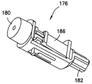
図24A~24Iは、一体型または単一式クリップを有する内側スリーブ176の別の例示的実施形態を示す。内側スリーブ176およびクリップの組合せは、金属またはプラスチックの単一片から形成することができ、または、それらは一体成形された材料の個々の部品から作ることもできる。内側スリーブ176は、カテーテルハブ(不図示)に入るように遠位方向に延びている対向部材180、および、外側スリーブ(不図示)に入るように遠位方向に延びている外側部材182を含む。外側部材182は、1つまたはより多くの放射状に延びるリブを有する中央円筒部を有している。内側スリーブ176のクリップ部は、遠位壁188から延びる第1のアーム184および第2のアーム186を有している。第1および第2のアーム184,186は、針(不図示)の先端を受けて収容するように、開いた向きと閉じた向きの間で移動可能である。図24A~24Iの例示的実施形態の構造を、必要に応じて、本明細書に開示される他の例示的実施形態の構造と組み合わせることができる。
Figures 24A-24I show another exemplary embodiment of an
上述した針シールドのいずれも、図25A~26Fに示すように、多用途のルアー作動血液制御カテーテルハブに関連して使用することができる。カテーテルは、カテーテルハブ14、および、カテーテルハブから延びる可撓性カテーテルチューブを含む。金属製ウェッジ136は、カテーテルチューブを保持するように、カテーテルハブ内に位置する。
セプタム138は、カテーテルハブ14を通る流体の流れを制御するように位置する。図25Bに最もよく表されるように、セプタム138は、セプタム138を通る望ましくない流体の流れを選択的に防止するように設計された1つまたはより多くの弾性のある開口部またはスリット140を有する。セプタム138は、アクチュエータ142に係合されたときに開く3つの三角形のフラップを形成する3つのスリット140を有している。セプタム138は、例えばシリコンゴムなどの弾性材料から作られる。
Any of the needle shields described above can be used in conjunction with the versatile luer actuated blood control catheter hub, as shown in Figures 25A-26F. The catheter includes a
セプタム138は軸方向流路139をさらに備える。流路139はセプタム138の外周に配置されている。様々な量および位置が考えられるが、互いから等距離にある8つの流路139が図示されている。セプタム138が貫通されない場合に、血液が入ることができ、および、空気がカテーテルハブの前部においてセプタム138の遠位端部から抜けることができるように、流路139は適切な幅および深さを持っている。同時に、流路139は、(少なくともしばらくの間)血液がセプタム138を通り過ぎて出て行くのを防止するために十分に小さい大きさとされている。このような構成は、血液中の分子間力が空気中の分子間力よりも大きいことにより可能である。図25Bに示すセプタム138は、本明細書で説明した実施形態のいずれにも使用することができる。当業者によって理解されるように、他の構成のセプタムを使用することもできる。
アクチュエータ142および付勢または戻し部材、例えば金属性またはプラスチック製の圧縮ばね144は、カテーテルハブ14内に位置している。アクチュエータ142は、スリット140を開きおよびカテーテルハブ14を通る流体の流れを可能にするように、セプタム138と係合する。付勢または戻し部材144は、弾性のあるスリット140が閉じることを可能にする位置にアクチュエータ142を戻すことが可能であり、カテーテルハブ14を通る流体の流れが防止される。
An
アクチュエータ142は、内部通路143Bを囲むアクチュエータバレル143Aを有している。アクチュエータバレル143Aは実質的に管状部材であり、および、内部通路143Bは実質的に円筒形である。管状部材は、アクチュエータのバレルを通るおよび周りの流体の流れを可能にする1つまたはより多くの開口部143Cを有している。アクチュエータバレルの第1の端部は、セプタムに係合する角を削がれた外面を持ったノーズを有している。円錐台形部145Aは、アクチュエータバレル143Aの第2の端部から延びている。円錐台形部145Aは、流体の流れが其処を通ることを可能にする1つまたはより多くの開口部145Bを有している。円筒部145Cは、雄型ルアーコネクタと係合するように円錐台形部145Aから延びている。角度が付けられた前面およびスロット147を有する1つまたはより多くのフックが、アクチュエータバレル143Aから延びている。
図25A~26Fに示された例示的実施形態において、付勢または戻し部材は、ばね144であり、例えば、遠位端および近位端を持った螺旋状の圧縮ばねである。ばね144は、金属、プラスチック、エラストマー、または他の適切な弾性材料から作ることができる。ばね144の遠位端は、カテーテルハブ14の内面と締まり嵌めを形成する。締まり嵌めは、ばね144を負荷がかかっている間でさえも保持するのに十分であることが可能であり、或いは、ばね144の遠位端はまた、セプタム138に当接することができる。
ばね144の近位端は、例えばフックを越えてスロットに嵌合することにより、アクチュエータ142に接続される。他の実施形態142において、アクチュエータ142と付勢部材144は一体構造になるように組み合わされる。様々な例示的実施形態において、カテーテルハブ14の内面、および/または、アクチュエータ142および/または付勢部材144の外面は、切り取り部、バンプ、突出部、歯部、または他の適切な構造を含み、カテーテルハブ14との間、および、付勢部材144との間、および、付勢部材144とアクチュエータ142の間にスナップ接続を形成する。
In the exemplary embodiment shown in Figures 25A-26F, the biasing or return member is a
The proximal end of
図26A~26Fは、アクチュエータ142および付勢部材144を持ったカテーテルハブ14の動作を示す。導入針12は、最初は、アクチュエータ142、セプタム138、ウェッジ136、および、カテーテルチューブ22を通って延びている。導入針12およびカテーテルチューブ22が患者に挿入された後、針12が引き抜かれ、セプタム138を閉じる。雄型ルアーコネクタ146がカテーテルハブ14内に挿入されるにしたがって、ルアーコネクタ146がアクチュエータ142に当接して遠位方向に移動させ、ばね144を圧縮する。ルアーコネクタ146のさらなる挿入は、アクチュエータ142をセプタム138を通って移動させ、スリット140を開き、および、流体がカテーテルハブ14を通って流れることを可能にする。
26A-26F illustrate operation of
ルアーコネクタ146が取り除かれると、ばね144がアクチュエータ142をセプタム138から外し、スリット140を閉じ、および、流体が其処を通って流れることを防ぐ。このことは、アクチュエータ142がルアーコネクタが取り除かれた後セプタム138内に残る使い捨て使用カテーテルとは対照的に、カテーテルアセンブリが複数のルアー接続を介して再利用されることを可能にする。しかしながら、アクチュエータ142および/またはばね144が無い使い捨てカテーテルは、本明細書中で説明される針シールドとともに使用することもできる。図25A~26Fの例示的実施形態の構造を、必要に応じて、本明細書に開示される他の例示的実施形態の構造と組み合わせることができる。
When
図27は、アクチュエータ254の例示的実施形態を示す。アクチュエータ254は、本明細書に開示された実施形態のいずれにおいても使用することができる。アクチュエータ254は、カテーテルハブアセンブリのセプタム238内にアクチュエータ254が貫入する際の摩擦を低減するノーズ258を含んでいる。アクチュエータ254は、アクチュエータ254の中心線に対して垂直な方向にアクチュエータ254を通って延在する開口部255をさらに含む。例えば、アクチュエータ254は、2つの矩形状の開口部255を含むことができるが、より多いことまたはより少ないことも考えられる。
FIG. 27 shows an exemplary embodiment of
アクチュエータ254はまた、アクチュエータ254の外面の遠位部分に沿ってアクチュエータ254の中心線に対し平行な面内で軸方向に延びる複数の溝257を備える。例えば、放射状に互いから実質的に等間隔の4つの溝257が、アクチュエータ254の遠位部分の外面に沿って存在することができ、より多いまたはより少ない溝257も考えられる。溝257は、アクチュエータ254内への深さを変更することができる。溝257は、アクチュエータ254の厚さを溝257が完全には貫通していないことから、開口部255とは異なる。
開口部255および溝257は、有利には、流体がカテーテルハブアセンブリ内を移動するのための増大領域を提供する。増大領域は、有利には、流体のフラッシングを可能にし、そして、セプタムの近位端および遠位端における流体の凝固を防止する。さらに、開口部255および複数の溝257は、有利には、流体の滞留を最小化し、および、よりいっそうの混合を可能にする。溝257は、さらに、動作中のアクチュエータの外面上をセプタムがシールすることを防止する。シール界面を形成しないことにより、流体が溝57を介してセプタムを通って漏れ、そして、追加のフラッシングを提供することが可能となる。
図28Aは、図27のアクチュエータ254をカテーテルハブアセンブリ内に示す。上述の実施形態と同様、カテーテルハブアセンブリは、カテーテルハブ214、セプタム238、および、付勢部材256をさらに含む。図示のように、アクチュエータ254の開口部255および溝257は、カテーテルハブ214内の流体の流れのためのより多くの領域を提供し、したがって、上述した利点を達成する。
Figure 28A shows the
図28Bおよび28Cは、付勢部材256が圧縮され、および、アクチュエータ254がセプタム238を貫通するときのカテーテルハブアセンブリを示す。カテーテルハブアセンブリは、アクチュエータ254の開口部255および/または溝257がセプタム238を随意的に貫きまたは貫通するように構成することができる。示された実施形態では、アクチュエータ254における開口部255はセプタム238を貫通していない。しかしながら、アクチュエータ254における溝257はセプタム238を貫通している。この構成は、上述した効果に加えて、溝257を通る流体の流れであって、セプタム138の近位端から遠位端への増加した流体の流れを可能にする。カテーテルアセンブリの動作が完了した後、アクチュエータ254は、付勢部材256によって加えられる力によりセプタム238から退避する。カテーテルアセンブリは、アクチュエータ254の押下時の複数の用途のために構成されている。本実施の形態で説明したアクチュエータなどの構造は、本出願を通して説明した構造と組み合わせて使用することができる。
28B and 28C show the catheter hub assembly as biasing
図29Aは、カテーテルハブアセンブリにおけるアクチュエータ364の別の実施形態を示す。カテーテルハブアセンブリは、サイドポート368を有するカテーテルハブ362を含む。サイドポート368は、カテーテルハブ362内の流体の流れに対して二次的アクセスを提供する。カテーテルハブ362のメインボアとサイドポート368の交差部は、スリーブ372を含む。スリーブ372は、選択的な流体連通をサイドポート368とカテーテルハブ362の間に提供する。具体的には、十分な流体圧力がサイドポート368を通じて加えられるとスリーブ372が圧縮する。スリーブ372の圧縮は、流体がカテーテルハブ362に入ることを可能にする。参照により本明細書に組み込まれる米国特許第4231367号への参照が、本明細書に記載されたタイプのカテーテルアセンブリにおけるサイドポートカテーテルに関してなされる。カテーテルハブアセンブリは、セプタム370と、アクチュエータ364に張力を与える付勢部材366とをさらに含む。
Figure 29A shows another embodiment of an
アクチュエータ364は、上述したものと同じ様にアクチュエータ364を通って延びる複数の開口部365を備える。開口部365について様々な量、サイズ、および、間隔が考えられるが、アクチュエータ364は、異なるサイズおよび間隔を有する4つの開口部365の2つの列を含む。図示のように、開口部365は、カテーテルハブ362内の流体の流れのためのより多くの領域を提供し、したがって、図27~28Cに関連して上で説明したのと同様の利点を達成する。
図29Bおよび29Cは、アクチュエータ364がセプタム370を貫通し、および、付勢部材366を圧縮するときのカテーテルハブアセンブリを示す。カテーテルハブアセンブリは、アクチュエータ364の開口部365がセプタム370に随意的に貫入するように構成されている。示された実施形態において、アクチュエータ364における開口部365は、セプタム370に貫入していない。この構成は、上述した効果に加えて、サイドポート368とカテーテルハブ362の間の増加した流体の流れを、セプタム370の近位端において可能にする。アクチュエータ364における開口部365がセプタム370に貫入する場合は、流体のいっそうの混合がまた、セプタム370の遠位端において起きる。
29B and 29C show the catheter hub assembly as
カテーテルアセンブリの動作が完了すると、アクチュエータ364は付勢部材366が加える力によってセプタム370から退避する。カテーテルアセンブリは、アクチュエータ364の押下時の複数の用途のために構成されている。本実施の形態で説明した、アクチュエータを含む構造は、本出願を通して説明した構造と組み合わせて使用することができる。
Upon completion of catheter assembly movement,
特定の例示的実施形態の前述の詳細な説明は、本発明の原理およびその実際の応用を説明する目的で提供されており、それにより、他の当業者が本発明を、様々な実施形態について、考えられる特定の用途に適した種々の変形と共に理解することを可能にする。この説明は、必ずしも網羅的であること、または開示された正確な形態に本発明を限定するものでない。本明細書に開示された実施形態および/または構成要素のいずれかを、具体的に開示されていない様々な追加の実施形態を形成するために互いに組み合わせることができる。したがって、さらなる実施形態が可能であり、本明細書および本発明の範囲内に包含されるものとする。仕様は別の方法で達成することができる、より一般的な目標を達成するために特定の例を記載している。 The foregoing detailed description of specific illustrative embodiments is provided for the purpose of illustrating the principles of the invention and its practical application so that others skilled in the art may understand the invention in its various embodiments. , together with various modifications suitable for the particular application contemplated. This description is not necessarily intended to be exhaustive or to limit the invention to the precise forms disclosed. Any of the embodiments and/or components disclosed herein can be combined together to form various additional embodiments not specifically disclosed. Accordingly, additional embodiments are possible and are intended to be included herein and within the scope of the invention. The specification describes specific examples to achieve a more general goal that can be achieved in another way.
本出願において使用される、用語「前部」、「後部」、「上部」、「下部」、「上方」、「下方」、および他の配向記述子は、本発明の例示的実施形態の説明を容易にするために意図されており、本発明の例示的実施形態の構造を任意の特定の位置または配向に限定するものではない。以下のような程度の規約、「実質的に」または「およそ」は、例えば、一般的な許容誤差が製造、組み立て、および実施形態の使用に関連し、所定の値の外側の妥当な範囲を参照するために当業者によって理解される。 The terms "front", "back", "upper", "lower", "upper", "lower" and other orientation descriptors used in this application are intended to describe exemplary embodiments of the present invention. and is not intended to limit the structure of the exemplary embodiments of the invention to any particular position or orientation. Terms of degree, such as "substantially" or "approximately," are, for example, common tolerances associated with manufacture, assembly, and use of the embodiments, and reasonable ranges outside of a given value. understood by those skilled in the art for reference.
Claims (12)
可撓性のカテーテルと、
カテーテルハブと、
遠位先端部を有する針であって、前記可撓性のカテーテル内に配置され、および、この針を露出させる第1の位置から第2の位置に移動する針と、
前記カテーテルハブと係合しおよび係合解除するように構成されたハウジングと、
前記ハウジング内に配置された針保護部材であって、前記針が前記第2の位置にあるときに前記針の前記遠位先端部を囲む針保護部材と、
を備え、
前記ハウジングは、前記針が前記第1の位置にあるときに前記カテーテルハブに係合し、および、
前記針が前記第2の位置に移動されたときに、前記ハウジングは前記カテーテルハブと係合解除する、カテーテルアセンブリ。 A catheter assembly comprising:
a flexible catheter;
a catheter hub;
a needle having a distal tip disposed within the flexible catheter and moved from a first position to a second position exposing the needle;
a housing configured to engage and disengage the catheter hub;
a needle guard disposed within the housing and surrounding the distal tip of the needle when the needle is in the second position;
with
the housing engages the catheter hub when the needle is in the first position; and
A catheter assembly, wherein the housing disengages the catheter hub when the needle is moved to the second position.
可撓性のカテーテルと、
カテーテルハブと、
遠位先端部を有する針であって、前記可撓性のカテーテル内に配置され、および、この針を露出させる第1の位置から第2の位置に移動する針と、
前記カテーテルハブと係合しおよび係合解除するように構成されたハウジングと、
前記ハウジング内に配置された針保護部材であって、前記針が前記第2の位置にあるときに前記針の前記遠位先端部を囲む針保護部材と、
を備え、
前記ハウジングと前記針保護部材は、前記針が前記第1の位置にあるときに前記カテーテルハブに係合し、および、
前記針が前記第2の位置に移動されたときに、前記針保護部材は前記カテーテルハブと係合解除し、前記ハウジングが前記カテーテルハブから係合解除することを可能にする、カテーテルアセンブリ。 A catheter assembly comprising:
a flexible catheter;
a catheter hub;
a needle having a distal tip disposed within the flexible catheter and moved from a first position to a second position exposing the needle;
a housing configured to engage and disengage the catheter hub;
a needle guard disposed within the housing and surrounding the distal tip of the needle when the needle is in the second position;
with
said housing and said needle protection member engage said catheter hub when said needle is in said first position; and
The catheter assembly of claim 1, wherein the needle protection member disengages the catheter hub when the needle is moved to the second position, allowing the housing to disengage from the catheter hub.
前記対向部材は、前記針が前記第1の位置にあるときに前記カテーテルハブに挿入されるように構成される、請求項6に記載のカテーテルアセンブリ。 the needle protection member includes an opposing member; and
7. The catheter assembly of Claim 6, wherein the opposing member is configured to be inserted into the catheter hub when the needle is in the first position.
Priority Applications (1)
| Application Number | Priority Date | Filing Date | Title |
|---|---|---|---|
| JP2024192827A JP2025010379A (en) | 2014-04-18 | 2024-11-01 | Catheter Assembly |
Applications Claiming Priority (8)
| Application Number | Priority Date | Filing Date | Title |
|---|---|---|---|
| US201461981223P | 2014-04-18 | 2014-04-18 | |
| US201461981312P | 2014-04-18 | 2014-04-18 | |
| US61/981,312 | 2014-04-18 | ||
| US61/981,223 | 2014-04-18 | ||
| US201462077760P | 2014-11-10 | 2014-11-10 | |
| US62/077,760 | 2014-11-10 | ||
| JP2019136251A JP7123016B2 (en) | 2014-04-18 | 2019-07-24 | catheter assembly |
| JP2021093222A JP7140884B2 (en) | 2014-04-18 | 2021-06-02 | catheter assembly |
Related Parent Applications (1)
| Application Number | Title | Priority Date | Filing Date |
|---|---|---|---|
| JP2021093222A Division JP7140884B2 (en) | 2014-04-18 | 2021-06-02 | catheter assembly |
Related Child Applications (1)
| Application Number | Title | Priority Date | Filing Date |
|---|---|---|---|
| JP2024192827A Division JP2025010379A (en) | 2014-04-18 | 2024-11-01 | Catheter Assembly |
Publications (1)
| Publication Number | Publication Date |
|---|---|
| JP2022168126A true JP2022168126A (en) | 2022-11-04 |
Family
ID=54324644
Family Applications (15)
| Application Number | Title | Priority Date | Filing Date |
|---|---|---|---|
| JP2016563040A Active JP6563419B2 (en) | 2014-04-18 | 2015-04-17 | The needle captures a secure connection for the catheter |
| JP2016563025A Active JP6659574B2 (en) | 2014-04-18 | 2015-04-17 | Needle capture safety interlock for catheter |
| JP2016563059A Active JP7067865B2 (en) | 2014-04-18 | 2015-04-17 | Multiple use blood control safety catheter assembly |
| JP2017554341A Active JP6903013B2 (en) | 2014-04-18 | 2016-04-15 | Catheter needle capture safety mutual locking device |
| JP2017554334A Active JP6752814B2 (en) | 2014-04-18 | 2016-04-15 | Multiple use blood control safety catheter assembly |
| JP2019085756A Active JP7199298B2 (en) | 2014-04-18 | 2019-04-26 | Multiple Use Blood Control Safety Catheter Assembly |
| JP2019136251A Active JP7123016B2 (en) | 2014-04-18 | 2019-07-24 | catheter assembly |
| JP2019200891A Active JP6896046B2 (en) | 2014-04-18 | 2019-11-05 | Needle capture safety interlock for catheters |
| JP2020138627A Active JP7096297B2 (en) | 2014-04-18 | 2020-08-19 | Multiple use blood control safety catheter assembly |
| JP2021093222A Active JP7140884B2 (en) | 2014-04-18 | 2021-06-02 | catheter assembly |
| JP2021110825A Active JP7558901B2 (en) | 2014-04-18 | 2021-07-02 | Multiple Use Blood Control Safety Catheter Assembly |
| JP2021170985A Active JP7531469B2 (en) | 2014-04-18 | 2021-10-19 | Multiple Use Blood Control Safety Catheter Assembly |
| JP2022143044A Pending JP2022168126A (en) | 2014-04-18 | 2022-09-08 | catheter assembly |
| JP2023081713A Active JP7580526B2 (en) | 2014-04-18 | 2023-05-17 | Multiple Use Blood Control Safety Catheter Assembly |
| JP2024192827A Pending JP2025010379A (en) | 2014-04-18 | 2024-11-01 | Catheter Assembly |
Family Applications Before (12)
| Application Number | Title | Priority Date | Filing Date |
|---|---|---|---|
| JP2016563040A Active JP6563419B2 (en) | 2014-04-18 | 2015-04-17 | The needle captures a secure connection for the catheter |
| JP2016563025A Active JP6659574B2 (en) | 2014-04-18 | 2015-04-17 | Needle capture safety interlock for catheter |
| JP2016563059A Active JP7067865B2 (en) | 2014-04-18 | 2015-04-17 | Multiple use blood control safety catheter assembly |
| JP2017554341A Active JP6903013B2 (en) | 2014-04-18 | 2016-04-15 | Catheter needle capture safety mutual locking device |
| JP2017554334A Active JP6752814B2 (en) | 2014-04-18 | 2016-04-15 | Multiple use blood control safety catheter assembly |
| JP2019085756A Active JP7199298B2 (en) | 2014-04-18 | 2019-04-26 | Multiple Use Blood Control Safety Catheter Assembly |
| JP2019136251A Active JP7123016B2 (en) | 2014-04-18 | 2019-07-24 | catheter assembly |
| JP2019200891A Active JP6896046B2 (en) | 2014-04-18 | 2019-11-05 | Needle capture safety interlock for catheters |
| JP2020138627A Active JP7096297B2 (en) | 2014-04-18 | 2020-08-19 | Multiple use blood control safety catheter assembly |
| JP2021093222A Active JP7140884B2 (en) | 2014-04-18 | 2021-06-02 | catheter assembly |
| JP2021110825A Active JP7558901B2 (en) | 2014-04-18 | 2021-07-02 | Multiple Use Blood Control Safety Catheter Assembly |
| JP2021170985A Active JP7531469B2 (en) | 2014-04-18 | 2021-10-19 | Multiple Use Blood Control Safety Catheter Assembly |
Family Applications After (2)
| Application Number | Title | Priority Date | Filing Date |
|---|---|---|---|
| JP2023081713A Active JP7580526B2 (en) | 2014-04-18 | 2023-05-17 | Multiple Use Blood Control Safety Catheter Assembly |
| JP2024192827A Pending JP2025010379A (en) | 2014-04-18 | 2024-11-01 | Catheter Assembly |
Country Status (14)
| Country | Link |
|---|---|
| US (14) | US10729890B2 (en) |
| EP (11) | EP4659779A2 (en) |
| JP (15) | JP6563419B2 (en) |
| KR (8) | KR20220136450A (en) |
| CN (7) | CN112675412B (en) |
| AU (16) | AU2015247346B2 (en) |
| BR (5) | BR112016024163B1 (en) |
| CA (4) | CA2945600C (en) |
| ES (5) | ES2843582T3 (en) |
| MX (7) | MX386914B (en) |
| MY (1) | MY189824A (en) |
| NZ (4) | NZ763557A (en) |
| SG (9) | SG11201608546TA (en) |
| WO (3) | WO2015161294A1 (en) |
Families Citing this family (104)
| Publication number | Priority date | Publication date | Assignee | Title |
|---|---|---|---|---|
| ATE424879T1 (en) | 2005-07-06 | 2009-03-15 | Vascular Pathways Inc | INTRAVENOUS CATHETER INSERTION DEVICE AND METHOD OF USE |
| ATE489989T1 (en) | 2007-05-07 | 2010-12-15 | Vascular Pathways Inc | INTRODUCTION OF AN INTRAVENOUS CATHETER AND BLOOD COLLECTION DEVICE AND METHOD OF USE |
| US10384039B2 (en) | 2010-05-14 | 2019-08-20 | C. R. Bard, Inc. | Catheter insertion device including top-mounted advancement components |
| US11925779B2 (en) | 2010-05-14 | 2024-03-12 | C. R. Bard, Inc. | Catheter insertion device including top-mounted advancement components |
| US9950139B2 (en) | 2010-05-14 | 2018-04-24 | C. R. Bard, Inc. | Catheter placement device including guidewire and catheter control elements |
| US9872971B2 (en) | 2010-05-14 | 2018-01-23 | C. R. Bard, Inc. | Guidewire extension system for a catheter placement device |
| US8932258B2 (en) | 2010-05-14 | 2015-01-13 | C. R. Bard, Inc. | Catheter placement device and method |
| US8690833B2 (en) | 2011-01-31 | 2014-04-08 | Vascular Pathways, Inc. | Intravenous catheter and insertion device with reduced blood spatter |
| EP2678065B1 (en) | 2011-02-25 | 2019-09-11 | C.R. Bard Inc. | Medical component insertion device including a retractable needle |
| USD903101S1 (en) | 2011-05-13 | 2020-11-24 | C. R. Bard, Inc. | Catheter |
| WO2014120741A1 (en) | 2013-01-30 | 2014-08-07 | Vascular Pathways, Inc. | Systems and methods for venipuncture and catheter placement |
| US10500376B2 (en) | 2013-06-07 | 2019-12-10 | Becton, Dickinson And Company | IV catheter having external needle shield and internal blood control septum |
| EP4659779A2 (en) | 2014-04-18 | 2025-12-10 | Becton, Dickinson and Company | Multi-use blood control safety catheter assembly |
| US10232146B2 (en) | 2014-09-05 | 2019-03-19 | C. R. Bard, Inc. | Catheter insertion device including retractable needle |
| CA3208226A1 (en) * | 2014-11-10 | 2016-05-19 | Becton, Dickinson And Company | Safety iv catheter with v-clip interlock and needle tip capture |
| US11511052B2 (en) | 2014-11-10 | 2022-11-29 | Becton, Dickinson And Company | Safety IV catheter with V-clip interlock and needle tip capture |
| USD903100S1 (en) | 2015-05-01 | 2020-11-24 | C. R. Bard, Inc. | Catheter placement device |
| AU2016265685B2 (en) | 2015-05-15 | 2020-04-09 | C.R. Bard, Inc. | Catheter placement device including an extensible needle safety component |
| US11207054B2 (en) | 2015-06-19 | 2021-12-28 | Novasignal Corp. | Transcranial doppler probe |
| PL3337549T3 (en) | 2015-08-18 | 2020-02-28 | B. Braun Melsungen Ag | Catheter devices with valves and related methods |
| CN112401882B (en) | 2015-09-03 | 2024-08-27 | 木兰医药技术股份有限公司 | Apparatus and method for maintaining sterility of sample containers |
| US10525237B2 (en) | 2015-10-28 | 2020-01-07 | Becton, Dickinson And Company | Ergonomic IV systems and methods |
| US10245416B2 (en) | 2015-10-28 | 2019-04-02 | Becton, Dickinson And Company | Intravenous catheter device with integrated extension tube |
| US10744305B2 (en) | 2015-10-28 | 2020-08-18 | Becton, Dickinson And Company | Ergonomic IV systems and methods |
| US10639455B2 (en) | 2015-10-28 | 2020-05-05 | Becton, Dickinson And Company | Closed IV access device with paddle grip needle hub and flash chamber |
| US10814106B2 (en) | 2015-10-28 | 2020-10-27 | Becton, Dickinson And Company | Soft push tabs for catheter adapter |
| US10549072B2 (en) | 2015-10-28 | 2020-02-04 | Becton, Dickinson And Company | Integrated catheter with independent fluid paths |
| JP6751292B2 (en) * | 2015-11-26 | 2020-09-02 | テルモ株式会社 | catheter |
| JP2019504670A (en) | 2016-01-05 | 2019-02-21 | ニューラル アナリティクス、インコーポレイテッド | System and method for determining clinical indicators |
| US11589836B2 (en) | 2016-01-05 | 2023-02-28 | Novasignal Corp. | Systems and methods for detecting neurological conditions |
| US10617388B2 (en) | 2016-01-05 | 2020-04-14 | Neural Analytics, Inc. | Integrated probe structure |
| US20170224962A1 (en) * | 2016-02-05 | 2017-08-10 | M. Samy Ahmed Hamboly | Safety Guidewire Introducer Assembly |
| KR101707181B1 (en) * | 2016-02-25 | 2017-02-15 | 김정규 | Safety catheter assembly |
| KR102579635B1 (en) | 2016-04-15 | 2023-09-18 | 백톤 디킨슨 앤드 컴퍼니 | Medical device with anti-rotation push tab |
| US11213656B2 (en) * | 2016-04-15 | 2022-01-04 | Becton, Dickinson And Company | Medical device with anti-rotation push tab |
| CA3021032A1 (en) * | 2016-04-25 | 2017-11-02 | Neural Analytics, Inc. | Probe structure |
| US11344220B2 (en) | 2016-05-13 | 2022-05-31 | Becton, Dickinson And Company | Invasive medical device cover with magnet |
| CN106362263A (en) * | 2016-08-30 | 2017-02-01 | 苏州鱼跃医疗科技有限公司 | Introducing needle protective device used for catheter assembly, catheter assembly and indwelling needle |
| US10032552B2 (en) * | 2016-08-30 | 2018-07-24 | Becton, Dickinson And Company | Cover for tissue penetrating device with integrated magnets and magnetic shielding |
| EP4424355A3 (en) | 2016-09-12 | 2024-11-20 | C. R. Bard, Inc. | Blood control for a catheter insertion device |
| WO2018053147A1 (en) | 2016-09-15 | 2018-03-22 | Becton, Dickinson And Company | Needle assembly for subcutaneous infusion set |
| US10238852B2 (en) | 2016-10-05 | 2019-03-26 | Becton, Dickinson And Company | Septum housing |
| WO2018094310A1 (en) | 2016-11-18 | 2018-05-24 | Bullington Gregory J | Systems and methods for sample collection with reduced hemolysis |
| WO2018132758A1 (en) | 2017-01-12 | 2018-07-19 | I-V Access Technology, Inc. | Catheter valves |
| MY205667A (en) * | 2017-02-24 | 2024-11-05 | Becton Dickinson Co | Catheter assembly |
| WO2018157339A1 (en) | 2017-03-01 | 2018-09-07 | C.R. Bard, Inc. | Catheter insertion device |
| CN108525103A (en) * | 2017-03-06 | 2018-09-14 | 迈得医疗工业设备股份有限公司 | The manufacturing method of hose and hose |
| SG10201701920QA (en) * | 2017-03-09 | 2018-10-30 | Becton Dickinson Co | Intravenous catheter assembly with cannula safety mechanism |
| KR102560266B1 (en) | 2017-03-17 | 2023-07-28 | 백톤 디킨슨 앤드 컴퍼니 | Mid-Line Catheter Placement Device |
| US10603446B2 (en) * | 2017-04-03 | 2020-03-31 | Becton, Dickinson And Company | IV catheter with integral extension set and a spring powered needle safety |
| EP4534203A3 (en) | 2017-06-09 | 2025-05-21 | Magnolia Medical Technologies, Inc. | Fluid control devices and methods of using the same |
| US10426929B2 (en) | 2017-07-19 | 2019-10-01 | Becton, Dickinson And Company | Integrated peripheral intra-venous catheter with improved extension tube port probe access |
| AU2018311081B2 (en) | 2017-08-04 | 2024-02-01 | Becton, Dickinson And Company | Needle and catheter insertion device |
| US11865106B2 (en) * | 2017-08-11 | 2024-01-09 | Shenzhen Hightide Biopharmaceutical, Ltd. | Methods and compositions for treatment of inflammatory bowel disease |
| US10406326B2 (en) | 2017-08-31 | 2019-09-10 | I-V Access Technology, Inc. | Methods and devices for vascular access |
| CN111212597B (en) | 2017-09-12 | 2023-04-11 | 木兰医药技术股份有限公司 | Fluid control device and method of use |
| WO2019065943A1 (en) | 2017-09-29 | 2019-04-04 | テルモ株式会社 | Catheter assembly and medical valve |
| JP7381189B2 (en) * | 2017-11-09 | 2023-11-15 | ニプロ株式会社 | valved needle assembly |
| US10828467B2 (en) * | 2017-11-30 | 2020-11-10 | Becton, Dickinson And Company | Catheter assembly |
| US11419531B2 (en) | 2017-12-07 | 2022-08-23 | Magnolia Medical Technologies, Inc. | Fluid control devices and methods of using the same |
| EP3501593B1 (en) * | 2017-12-22 | 2024-08-07 | Roche Diabetes Care GmbH | Septum arrangement |
| CA3248366A1 (en) * | 2018-01-31 | 2025-02-21 | Smiths Medical Asd, Inc. | Releasable safety catheter insertion assembly |
| CN111801133B (en) | 2018-03-07 | 2022-12-06 | 巴德阿克塞斯系统股份有限公司 | Guidewire advancement and blood flashback system for medical device insertion systems |
| US11501661B2 (en) | 2018-03-29 | 2022-11-15 | Cae Healthcare Canada Inc. | Method and system for simulating an insertion of an elongated instrument into a subject |
| KR102277465B1 (en) * | 2018-04-17 | 2021-07-15 | 최민기 | Blood lancet |
| US11534591B2 (en) * | 2018-07-17 | 2022-12-27 | Becton, Dickinson And Company | Systems and methods for facilitating instrument delivery through a peripheral intravenous catheter |
| USD921884S1 (en) | 2018-07-27 | 2021-06-08 | Bard Access Systems, Inc. | Catheter insertion device |
| US11406810B2 (en) * | 2018-09-10 | 2022-08-09 | Beeton, Dickinson and Company | Systems and methods of facilitating instrument delivery to a catheter assembly |
| WO2020116363A1 (en) * | 2018-12-04 | 2020-06-11 | テルモ株式会社 | Catheter assembly and catheter indwelling body |
| US11850377B2 (en) | 2018-12-17 | 2023-12-26 | B. Braun Melsungen Ag | Catheter assemblies and related methods |
| CN212347338U (en) * | 2018-12-17 | 2021-01-15 | B.布劳恩梅尔松根股份公司 | Conduit assembly |
| US11786155B2 (en) | 2019-02-08 | 2023-10-17 | Magnolia Medical Technologies, Inc. | Devices and methods for bodily fluid collection and distribution |
| AU2020234829B2 (en) | 2019-03-11 | 2025-11-13 | Magnolia Medical Technologies, Inc. | Fluid control devices and methods of using the same |
| WO2020195848A1 (en) | 2019-03-28 | 2020-10-01 | テルモ株式会社 | Catheter assembly |
| WO2020209368A1 (en) * | 2019-04-11 | 2020-10-15 | ニプロ株式会社 | Indwelling needle assembly |
| CN113507958B (en) * | 2019-04-23 | 2023-05-12 | 史密斯医疗Asd公司 | Catheterization apparatus with improved push tab and tip protector assembly |
| US11344704B2 (en) * | 2019-07-11 | 2022-05-31 | Becton, Dickinson And Company | Catheter system facilitating reduced drag force |
| US11559665B2 (en) | 2019-08-19 | 2023-01-24 | Becton, Dickinson And Company | Midline catheter placement device |
| EP4028104A4 (en) | 2019-09-10 | 2023-12-13 | MedSource International LLC | An intravenous catheter device |
| USD929580S1 (en) * | 2019-09-13 | 2021-08-31 | Becton, Dickinson And Company | Catheter hub device |
| JP7453356B2 (en) * | 2019-09-20 | 2024-03-19 | バード・ペリフェラル・バスキュラー・インコーポレーテッド | Intravenous catheter placement device |
| IT201900019842A1 (en) | 2019-10-28 | 2021-04-28 | Medi Pro S R L | BIOMEDICAL DEVICE FOR ARTERIAL ACCESS |
| US11872360B2 (en) * | 2019-11-11 | 2024-01-16 | Becton, Dickinson And Company | Catheter systems and methods for flashback visualization at various blood pressures |
| CN110975061B (en) * | 2019-11-19 | 2021-09-10 | 山东省千佛山医院 | Puncture-preventing remaining needle capable of continuously supplying liquid |
| CA3164339A1 (en) | 2019-12-11 | 2021-06-17 | Magnolia Medical Technologies, Inc. | Fluid transfer devices with integrated flow-based assay and methods of using the same |
| US12458780B2 (en) * | 2019-12-18 | 2025-11-04 | Becton, Dickinson And Company | Inhibiting fluid leakage and splatter in catheter devices and systems |
| KR20220133213A (en) * | 2020-01-24 | 2022-10-04 | 벡톤 디킨슨 앤드 컴퍼니 | Antithrombotic Catheter Assembly |
| DE102020107773A1 (en) * | 2020-03-20 | 2021-09-23 | Martin Butz | Indwelling cannula |
| US12201791B2 (en) * | 2020-03-31 | 2025-01-21 | Becton, Dickinson And Company | Intravenous device assembly with needle guard |
| CN111888586B (en) * | 2020-07-24 | 2025-02-21 | 贝普医疗科技股份有限公司 | A needle-puncture prevention device with a limited spring piece and a stopper |
| CN111888587B (en) * | 2020-07-24 | 2024-12-27 | 贝普医疗科技股份有限公司 | A needle-stick prevention device with elastic collar and stopper |
| JP7564505B2 (en) * | 2020-07-30 | 2024-10-09 | ニプロ株式会社 | Needle Assembly |
| WO2022172281A1 (en) * | 2021-02-10 | 2022-08-18 | Neeraj Gupta | Intravenous cannula |
| US12337123B2 (en) | 2021-05-06 | 2025-06-24 | Medsource Labs, Llc | Safety intravenous cannula |
| EP4346978A1 (en) * | 2021-05-27 | 2024-04-10 | Becton, Dickinson and Company | Retainer element to secure a catheter adapter valve |
| US12186497B2 (en) | 2022-01-14 | 2025-01-07 | Medsource International Llc | Intravenous cannula |
| WO2023146794A1 (en) * | 2022-01-27 | 2023-08-03 | Smiths Medical Asd, Inc. | Intravenous catheter assemblies including closed system catheter assemblies and needle insertion assemblies therefor |
| US11607525B1 (en) * | 2022-06-30 | 2023-03-21 | I-V Access Technology, Inc. | Methods and devices for vascular access |
| US20240001079A1 (en) * | 2022-06-30 | 2024-01-04 | I-V Access Technology, Inc. | Methods and devices for vascular access |
| KR102480888B1 (en) * | 2022-09-15 | 2022-12-26 | 주식회사 덕우메디칼 | safety catheter assembly |
| US20240325709A1 (en) * | 2023-03-28 | 2024-10-03 | Carefusion 303, Inc. | Straight canula groove hemoshield connector |
| WO2025059136A1 (en) * | 2023-09-13 | 2025-03-20 | Edwards Lifesciences Corporation | Passive seal for introducers |
| WO2025264842A1 (en) * | 2024-06-18 | 2025-12-26 | Venocare, Inc. | Hypodermic needles and methods of manufacture |
| CN119792764B (en) * | 2025-03-11 | 2025-06-13 | 广州保瑞医疗技术有限公司 | Improved generation prevents reverse flow through periphery and puts into central venous catheter |
Citations (4)
| Publication number | Priority date | Publication date | Assignee | Title |
|---|---|---|---|---|
| US20090088696A1 (en) * | 2007-09-28 | 2009-04-02 | Becton, Dickinson And Company | Catheter insertion device with automatic safety barrier |
| JP2012519057A (en) * | 2009-03-02 | 2012-08-23 | ベクトン・ディキンソン・アンド・カンパニー | Bidirectional cannula feature capture mechanism |
| WO2012139034A1 (en) * | 2011-04-07 | 2012-10-11 | Erskine Medical Llc | Needle shielding device |
| JP2013527005A (en) * | 2010-06-02 | 2013-06-27 | スミス・メディカル・エイエスディ・インコーポレーテッド | Tip protector for safety catheter |
Family Cites Families (260)
| Publication number | Priority date | Publication date | Assignee | Title |
|---|---|---|---|---|
| US1850961A (en) | 1930-11-08 | 1932-03-22 | Mortenson Engineering Co | Retaining means for building materials |
| US3585996A (en) | 1968-07-11 | 1971-06-22 | Levoy S Corp | Arterial catheter placement unit and method of use |
| SE401785B (en) | 1976-10-26 | 1978-05-29 | Viggo Ab | DEVICE AT AN INFUSION NEEDLE UNIT |
| DE2817102C2 (en) | 1978-04-19 | 1985-01-24 | Dr. Eduard Fresenius, Chemisch-pharmazeutische Industrie KG, 6380 Bad Homburg | Connector for plastic cannulas or venous catheters |
| US4332249A (en) | 1980-08-01 | 1982-06-01 | Sherwood Medical Industries, Inc. | Filter and valve assembly for hypodermic syringe |
| US4482591A (en) | 1983-03-08 | 1984-11-13 | J. T. Baker Chemical Company | Polyvinyl butyrate pellicle compositions and pellicles thereof for projection printing |
| US4524805A (en) | 1983-07-08 | 1985-06-25 | Hoffman Allan C | Normally closed duckbill valve and method of manufacture |
| US4622964A (en) | 1983-09-28 | 1986-11-18 | O-Two Systems International Inc. | Valve for breathing device |
| US5116021A (en) | 1986-03-04 | 1992-05-26 | Deka Products Limited Partnership | Quick-disconnect valve |
| US4809679A (en) | 1986-11-19 | 1989-03-07 | Olympus Optical Co., Ltd. | Forceps plug for endoscopes |
| GB8627808D0 (en) | 1986-11-20 | 1986-12-17 | Cox J A | Sampling liquids from human/animal body |
| US4762516A (en) | 1987-03-05 | 1988-08-09 | Luther Medical Products, Inc. | Assembly of needle catheter protector |
| US4747831A (en) | 1987-04-29 | 1988-05-31 | Phase Medical, Inc. | Cannula insertion set with safety retracting needle |
| DE3721299A1 (en) | 1987-06-27 | 1989-01-12 | Braun Melsungen Ag | CATHETER DEVICE |
| US4850961A (en) | 1987-07-30 | 1989-07-25 | Wanderer Alan A | Indwelling placement device with guard |
| US4842591A (en) | 1988-01-21 | 1989-06-27 | Luther Ronald B | Connector with one-way septum valve, and assembly |
| US5135489A (en) | 1988-01-25 | 1992-08-04 | Baxter International Inc. | Pre-slit injection site and tapered cannula |
| DE3809127C1 (en) * | 1988-03-18 | 1989-04-13 | B. Braun Melsungen Ag, 3508 Melsungen, De | |
| US4952207A (en) | 1988-07-11 | 1990-08-28 | Critikon, Inc. | I.V. catheter with self-locating needle guard |
| US4978344A (en) | 1988-08-11 | 1990-12-18 | Dombrowski Mitchell P | Needle and catheter assembly |
| US4946133A (en) | 1988-11-21 | 1990-08-07 | Schneider (U.S.A.) Inc., A Pfizer Co. | Hemostasis valve |
| ATE129163T1 (en) | 1989-02-01 | 1995-11-15 | Sero Guard Corp | SELF-ACTIVE NEEDLE GUARD FOR A DISPOSABLE HYPODERMIC SYRINGE. |
| US5662610A (en) | 1989-02-01 | 1997-09-02 | Sircom; Richard C. | Automatic needle guard tip protection |
| US5458658A (en) | 1989-02-01 | 1995-10-17 | Sero-Guard Corporation | Positive locking needle-mounted needle guard for needle supported catheters |
| US5000740A (en) | 1989-04-10 | 1991-03-19 | Critikon, Inc. | Catheter with needle guard |
| US5092845A (en) | 1989-07-10 | 1992-03-03 | Critikon, Inc. | Catheter with needle gasket |
| JPH03170612A (en) | 1989-11-29 | 1991-07-24 | Kawasaki Steel Corp | Vacuum degassing apparatus |
| DE4000764A1 (en) * | 1990-01-12 | 1991-07-18 | Braun Melsungen Ag | APPROACH |
| US5053014A (en) | 1990-02-01 | 1991-10-01 | Critikon, Inc. | Catheter with controlled valve |
| US5049128A (en) * | 1990-02-06 | 1991-09-17 | Duquette Irene A | Valved infusion port |
| US4948092A (en) | 1990-03-07 | 1990-08-14 | Royce Medical Company | Combined check valve and fluid pressure relief valve |
| US5062836A (en) | 1990-03-14 | 1991-11-05 | The Kendall Company | Placement device for a catheter and guide wire |
| US5558651A (en) | 1990-04-20 | 1996-09-24 | Becton Dickinson And Company | Apparatus and method for a needle tip cover |
| USRE38996E1 (en) | 1990-04-20 | 2006-02-28 | Becton, Dickinson And Company | Needle tip cover |
| FR2663836B1 (en) | 1990-04-20 | 1994-09-23 | Jean Perisse | MULTIBLOCK ORTHOPEDIC OR DENTAL IMPLANT. |
| US5085645A (en) | 1990-08-15 | 1992-02-04 | Becton, Dickinson And Company | Apparatus and method for a catheter adapter with valve |
| US5032116A (en) | 1991-01-09 | 1991-07-16 | Becton, Dickinson And Company | Flashback plug |
| US5290246A (en) | 1991-01-18 | 1994-03-01 | Terumo Kabushiki Kaisha | Piercing needle |
| US5092853A (en) * | 1991-02-04 | 1992-03-03 | Couvertier Ii Douglas | Automatic retractable medical needle and method |
| US5156596A (en) * | 1991-02-04 | 1992-10-20 | Menlo Care, Inc. | Catheter with changeable number of lumens |
| DE9105229U1 (en) | 1991-04-27 | 1991-06-13 | B. Braun Melsungen Ag, 3508 Melsungen | Valve device for a catheter |
| US5228453A (en) | 1991-05-07 | 1993-07-20 | Target Therapeutics, Inc. | Catheter guide wire |
| GB9120416D0 (en) | 1991-09-25 | 1991-11-06 | Sterimatic Holdings Ltd | Catheter placement units |
| US5215528C1 (en) | 1992-02-07 | 2001-09-11 | Becton Dickinson Co | Catheter introducer assembly including needle tip shield |
| WO1994003224A1 (en) | 1992-07-31 | 1994-02-17 | Luckhurst, Anthony, Henry, William | Needle protective device |
| US5215525A (en) | 1992-09-29 | 1993-06-01 | Sturman Warren M | Safety casing for intravenous catheter needle |
| ATE204493T1 (en) | 1992-11-24 | 2001-09-15 | Braun Melsungen Ag | CATHETERIZATION UNIT |
| US5269771A (en) * | 1993-02-24 | 1993-12-14 | Thomas Medical Products, Inc. | Needleless introducer with hemostatic valve |
| US5425465A (en) | 1993-03-03 | 1995-06-20 | Healy; Patrick M. | Valved medication container |
| US5391152A (en) | 1993-03-12 | 1995-02-21 | C. R. Bard, Inc. | Catheter interlock assembly |
| DE4311715C2 (en) | 1993-04-08 | 1996-02-01 | Fresenius Ag | Port cannula |
| US5300045A (en) | 1993-04-14 | 1994-04-05 | Plassche Jr Walter M | Interventional needle having an automatically capping stylet |
| US5417659A (en) | 1993-07-20 | 1995-05-23 | Devon Industries, Inc. | Surgical instrument sharp end foil |
| US5584809A (en) | 1993-07-20 | 1996-12-17 | Graphic Controls Corporation | Safety catheter |
| US5697907A (en) | 1993-07-20 | 1997-12-16 | Graphic Controls Corporation | Safety catheter |
| US5352205A (en) | 1993-09-16 | 1994-10-04 | Lawrence Dales | Bloodless insertion catheter assembly |
| US5419766A (en) | 1993-09-28 | 1995-05-30 | Critikon, Inc. | Catheter with stick protection |
| JP2584597B2 (en) | 1993-09-29 | 1997-02-26 | ベクトン・ディッキンソン・アンド・カンパニー | Catheter introduction device with blood seal |
| CA2135706C (en) | 1993-11-15 | 1999-06-15 | Walter E. Cover | Retractable-needle cannula insertion set with refinements to better control leakage, retraction speed, and reuse |
| US5348544A (en) | 1993-11-24 | 1994-09-20 | Becton, Dickinson And Company | Single-handedly actuatable safety shield for needles |
| US5405323A (en) | 1994-02-22 | 1995-04-11 | Aeroquip Corporation | Catheter check valve assembly |
| GB2292525B (en) | 1994-08-24 | 1998-07-01 | Sterimatic Holdings Ltd | Catheter placement units |
| US5423766A (en) | 1994-08-26 | 1995-06-13 | Becton, Dickinson And Company | Safety shield having spring tether |
| DE4442352C1 (en) | 1994-11-29 | 1995-12-21 | Braun Melsungen Ag | Valve arrangement provided in connector for use e.g. with cannula |
| US5520666A (en) | 1994-12-06 | 1996-05-28 | Abbott Laboratories | Valved intravenous fluid line connector |
| US5501675A (en) | 1994-12-27 | 1996-03-26 | Becton, Dickinson And Company | Safety catheter assembly having safety stop push button |
| CA2168615A1 (en) | 1995-03-07 | 1996-09-08 | Timothy J. Erskine | Catheter-advancement actuated needle retraction system |
| US5596996A (en) | 1995-03-30 | 1997-01-28 | Medtronic, Inc. | High support nitinol tube guidewire with plastic plug transition |
| IT1285266B1 (en) | 1996-02-26 | 1998-06-03 | Borla Ind | CONNECTOR WITH PROTECTION VALVE FOR INFUSION / TRANSFUSION AND SIMILAR MEDICAL LINES. |
| US6629959B2 (en) | 1996-02-27 | 2003-10-07 | Injectimed, Inc. | Needle tip guard for percutaneous entry needles |
| EP0891198B1 (en) * | 1996-02-27 | 2005-06-08 | Injectimed, Inc. | Needle tip guard for hypodermic needles |
| US5879337A (en) | 1997-02-27 | 1999-03-09 | Injectimed, Inc. | Needle tip guard for hypodermic needles |
| US5817069A (en) | 1996-02-28 | 1998-10-06 | Vadus, Inc. | Valve assembly |
| GB9605206D0 (en) | 1996-03-12 | 1996-05-15 | Boc Group Plc | Medical devices |
| US5865806A (en) | 1996-04-04 | 1999-02-02 | Becton Dickinson And Company | One step catheter advancement automatic needle retraction system |
| US5749857A (en) | 1996-04-25 | 1998-05-12 | Cuppy; Michael J. | Catheter system |
| US5830190A (en) | 1996-06-11 | 1998-11-03 | Becton Dickinson And Company | Protected needle catheter placement device having needle placement visualization features and method for its use |
| US5840046A (en) | 1996-06-21 | 1998-11-24 | Medtronic, Inc. | Guidewire having hydrophilic coating |
| CA2261938C (en) | 1996-08-07 | 2004-07-13 | Vadus, Inc. | Needle protector |
| JP3819491B2 (en) | 1996-08-20 | 2006-09-06 | 東郷メディキット株式会社 | Puncture needle for catheter introduction |
| US5867490A (en) | 1996-11-05 | 1999-02-02 | Worldspace International Network, Inc. | Direct radio broadcast receiver for providing frame synchronization and correlation for time division multiplexed transmissions |
| US6883778B1 (en) * | 1996-11-18 | 2005-04-26 | Nypro Inc. | Apparatus for reducing fluid drawback through a medical valve |
| US5772636A (en) | 1996-12-02 | 1998-06-30 | Becton Dickinson And Company | Catheter assembly with interlocking telescoping needle shield |
| US5954698A (en) | 1997-01-08 | 1999-09-21 | Vadus, Inc. | Catheter apparatus having valved catheter hub and needle protector |
| US5967490A (en) | 1997-01-08 | 1999-10-19 | Vadus, Inc. | Catheter hubs having a valve |
| US5911710A (en) | 1997-05-02 | 1999-06-15 | Schneider/Namic | Medical insertion device with hemostatic valve |
| JP3786312B2 (en) | 1997-05-20 | 2006-06-14 | テルモ株式会社 | catheter |
| US6616630B1 (en) | 1997-08-20 | 2003-09-09 | B. Braun Melsungen A.G. | Spring clip safety IV catheter |
| US8382721B2 (en) | 1997-08-20 | 2013-02-26 | B. Braun Melsungen Ag | Spring clip safety IV catheter |
| US6117108A (en) | 1997-08-20 | 2000-09-12 | Braun Melsungen Ag | Spring clip safety IV catheter |
| DE20103363U1 (en) | 2001-02-26 | 2001-05-17 | Braun Melsungen Ag | Protection device for an injection needle |
| US8211070B2 (en) | 1997-08-20 | 2012-07-03 | B. Braun Melsungen Ag | Spring clip safety IV catheter |
| EP1030702B8 (en) | 1997-11-12 | 2004-11-10 | MDC Investment Holdings, Inc. | Catheter insertion device with retractable needle |
| NL1007997C2 (en) | 1998-01-09 | 1999-07-12 | Cordis Europ | Device for inserting an elongated medical device. |
| US6749588B1 (en) | 1998-04-09 | 2004-06-15 | Becton Dickinson And Company | Catheter and introducer needle assembly with needle shield |
| US6379333B1 (en) | 1998-04-09 | 2002-04-30 | Becton, Dickinson And Company | Catheter and introducer needle assembly with needle shield |
| US6689102B2 (en) * | 1998-07-31 | 2004-02-10 | Albany Medical College | Safety intravenous catheter assembly |
| US6221047B1 (en) | 1998-07-31 | 2001-04-24 | Albany Medical College | Safety intravenous catheter assembly and method for use with a needle |
| US6213978B1 (en) | 1998-10-27 | 2001-04-10 | Cherie A. Voyten | Intravenous catheter insertion apparatus |
| US6452486B1 (en) | 1999-01-21 | 2002-09-17 | Premier Fulfillment, Inc. | Dual-igniter airbag control switch |
| US7029492B1 (en) | 1999-03-05 | 2006-04-18 | Terumo Kabushiki Kaisha | Implanting stent and dilating device |
| JP4518609B2 (en) | 1999-03-05 | 2010-08-04 | テルモ株式会社 | Indwelling stent |
| WO2001012249A1 (en) | 1999-08-12 | 2001-02-22 | Lynn Lawrence A | Luer receiving vascular access system |
| US6224569B1 (en) | 1999-09-24 | 2001-05-01 | Becton, Dickinson And Company | Compact needle point shield |
| JP2001115630A (en) | 1999-10-15 | 2001-04-24 | Misawa Homes Co Ltd | Sleeper installation method |
| DE29921084U1 (en) | 1999-12-01 | 2000-02-17 | B. Braun Melsungen Ag, 34212 Melsungen | Short catheter |
| FR2802432B1 (en) | 1999-12-16 | 2002-03-08 | Vygon | AUTOMATIC SHUTTER CONNECTOR FOR CONNECTING A LIQUID INJECTION HEAD TO AN INJECTION OUTPUT |
| US6234999B1 (en) | 2000-01-18 | 2001-05-22 | Becton, Dickinson And Company | Compact needle shielding device |
| US6595954B1 (en) * | 2000-03-13 | 2003-07-22 | Luther Research Partners, Llc | Insertion needle and soft catheter system with tip protector |
| US6972002B2 (en) | 2000-04-28 | 2005-12-06 | Specialized Health Products, Inc. | Passively activated safety shield for a catheter insertion needle |
| US20040078690A1 (en) | 2000-05-30 | 2004-04-22 | Yasuo Kohashi | Program counter trace system, program counter trace method, and semiconductor device |
| ES2287138T3 (en) | 2000-06-09 | 2007-12-16 | Becton Dickinson And Company | CATETER AND INTRODUCTING NEEDLE ASSEMBLY WITH NEEDLE PROTECTION. |
| JP4942256B2 (en) | 2000-06-12 | 2012-05-30 | テルモ株式会社 | Puncture and indwelling needle assembly |
| US6699221B2 (en) | 2000-06-15 | 2004-03-02 | Vincent L. Vaillancourt | Bloodless catheter |
| US20040204689A1 (en) * | 2000-08-14 | 2004-10-14 | Lynn Lawrence A. | Catheter and needle assembly with dual sealing |
| JP4996015B2 (en) * | 2001-03-12 | 2012-08-08 | メディキット株式会社 | Indwelling catheter |
| US6702249B2 (en) | 2001-03-19 | 2004-03-09 | Seiko Instruments Inc. | Pressure-variable valve device and set-pressure adjusting device for the valve device |
| DE20106697U1 (en) | 2001-04-18 | 2001-10-31 | B. Braun Melsungen Ag, 34212 Melsungen | Catheter introducer |
| US6506181B2 (en) | 2001-05-25 | 2003-01-14 | Becton, Dickinson And Company | Catheter having a low drag septum |
| USD459802S1 (en) | 2001-05-25 | 2002-07-02 | Becton, Dickinson And Company | Integrated catheter |
| ITBO20010497A1 (en) | 2001-07-31 | 2003-01-31 | Delta Med S R L | PROTECTION DEVICE FOR NEEDLE-CANNULA |
| US6964406B2 (en) * | 2001-08-10 | 2005-11-15 | Alaris Medical Systems, Inc. | Valved male luer |
| US6623458B2 (en) | 2001-09-26 | 2003-09-23 | B. Braun Melsungen, Ag | Spring launched needle safety clip |
| US6652486B2 (en) | 2001-09-27 | 2003-11-25 | Medex, Inc. | Safety catheter |
| US20040030294A1 (en) * | 2001-11-28 | 2004-02-12 | Mahurkar Sakharam D. | Retractable needle single use safety syringe |
| DE60208933T2 (en) | 2001-11-30 | 2006-10-26 | Novo Nordisk A/S | NEEDLE SAFETY DEVICE |
| US7267661B2 (en) | 2002-06-17 | 2007-09-11 | Iradimed Corporation | Non-magnetic medical infusion device |
| DE20210394U1 (en) | 2002-07-04 | 2002-09-12 | B. Braun Melsungen Ag, 34212 Melsungen | catheter introducer |
| US7601141B2 (en) | 2002-11-26 | 2009-10-13 | Nexus Medical, Llc | Pressure actuated flow control valve |
| EP1558311B1 (en) | 2003-02-11 | 2006-12-06 | Salvus Technology Limited | A safety needle |
| USD491266S1 (en) | 2003-03-10 | 2004-06-08 | Becton Dickinson And Company | Integrated catheter |
| US6871838B2 (en) * | 2003-04-03 | 2005-03-29 | B. Braun Medical Inc. | Injection port valve |
| US7470254B2 (en) | 2003-08-18 | 2008-12-30 | Medical Components, Inc. | Needle with sealing valve |
| US7632245B1 (en) | 2003-08-18 | 2009-12-15 | Medrad, Inc. | Devices, systems and methods for delivery of a fluid into a patient during a magnetic resonance procedure |
| US20050075609A1 (en) | 2003-10-01 | 2005-04-07 | Latona Patrick C. | Protective needle clips |
| US7988664B2 (en) | 2004-11-01 | 2011-08-02 | Tyco Healthcare Group Lp | Locking clip with trigger bushing |
| US7226434B2 (en) * | 2003-10-31 | 2007-06-05 | Tyco Healthcare Group Lp | Safety shield |
| US8500690B2 (en) * | 2004-07-01 | 2013-08-06 | Becton, Dickinson And Company | Passively shielding needle device |
| US7651476B2 (en) | 2004-09-28 | 2010-01-26 | B. Braun Medical Inc. | Protective clips |
| US8403890B2 (en) | 2004-11-29 | 2013-03-26 | C. R. Bard, Inc. | Reduced friction catheter introducer and method of manufacturing and using the same |
| US8926564B2 (en) | 2004-11-29 | 2015-01-06 | C. R. Bard, Inc. | Catheter introducer including a valve and valve actuator |
| US7731705B2 (en) * | 2005-01-10 | 2010-06-08 | Wardle John L | Eluting coils and methods of deploying and retrieving |
| US20060178635A1 (en) | 2005-02-08 | 2006-08-10 | Callaway George H | Easy entry catheters |
| US8303543B2 (en) | 2005-03-07 | 2012-11-06 | Ramzi Abulhaj | Bloodless catheter and needle shielding catheter insertion apparatus |
| ES2616073T3 (en) | 2005-03-07 | 2017-06-09 | Erskine Medical Llc | Needle protection device |
| EP1874393B1 (en) * | 2005-04-27 | 2017-09-06 | C.R.Bard, Inc. | Infusion apparatuses |
| US7998134B2 (en) * | 2007-05-16 | 2011-08-16 | Icu Medical, Inc. | Medical connector |
| US7597681B2 (en) * | 2005-08-08 | 2009-10-06 | Smiths Medical Asd, Inc. | Needle guard mechanism with shroud |
| US8251950B2 (en) * | 2005-08-08 | 2012-08-28 | Smiths Medical Asd, Inc. | Needle guard clip with heel |
| US20070083162A1 (en) | 2005-10-11 | 2007-04-12 | Span-America Medical Systems, Inc. | Valve for intravenous catheter |
| US7798994B2 (en) * | 2005-11-15 | 2010-09-21 | Becton, Dickinson And Company | Needle shield to septum interconnect |
| WO2007070544A2 (en) * | 2005-12-13 | 2007-06-21 | Cook Incorporated | Implantable medical device using palladium |
| US7641757B2 (en) * | 2006-01-12 | 2010-01-05 | Pacesetter, Inc. | Method of making a tubular body for a catheter, sheath or lead |
| US7591484B2 (en) | 2006-01-27 | 2009-09-22 | Cincinnati Test Systems, Inc. | Quick-connect fitting |
| EP1842513B1 (en) | 2006-04-07 | 2014-09-10 | The Procter and Gamble Company | Absorbent article having nonwoven lateral zones |
| JP5124566B2 (en) * | 2006-05-16 | 2013-01-23 | フレキシキャス リミテッド | Catheter insertion device and method of use thereof |
| US7722569B2 (en) * | 2006-05-22 | 2010-05-25 | Becton, Dickinson And Company | Catheter assembly with tip shield closure |
| US8235945B2 (en) | 2006-06-08 | 2012-08-07 | Rishi Baid | Safety device to cover the needle tip of intravenous catheter apparatus |
| CA2838409C (en) | 2006-07-11 | 2016-01-05 | Refocus Group, Inc. | Scleral prosthesis for treating presbyopia and other eye disorders and related devices and methods |
| CN101112639B (en) * | 2006-07-27 | 2012-07-18 | 贝克顿·迪金森公司 | Vessel having a safeguard device and introducing needle component |
| CN101112638B (en) | 2006-07-27 | 2011-06-08 | 贝克顿·迪金森公司 | Catheter and introducer needle assembly with safety device |
| US8382718B2 (en) | 2006-07-31 | 2013-02-26 | B. Braun Melsungen Ag | Needle assembly and components thereof |
| US8308691B2 (en) | 2006-11-03 | 2012-11-13 | B. Braun Melsungen Ag | Catheter assembly and components thereof |
| EP2066369A4 (en) * | 2006-09-29 | 2013-04-03 | Covidien Lp | Surgical fluid transfer apparatus |
| JP4994775B2 (en) | 2006-10-12 | 2012-08-08 | 日本コヴィディエン株式会社 | Needle point protector |
| US9011382B2 (en) | 2006-11-22 | 2015-04-21 | Becton, Dickinson And Company | Vascular access device blood sealing and exposure prevention |
| US9056188B2 (en) * | 2006-11-22 | 2015-06-16 | Becton, Dickinson And Company | Needle shielding flag structures |
| US7744567B2 (en) | 2006-11-22 | 2010-06-29 | Becton, Dickinson And Company | Reducing withdrawal force in a safety IV catheter |
| US9220871B2 (en) | 2006-11-22 | 2015-12-29 | Becton, Dickinson And Company | Needle shielding pawl structures |
| JP4909097B2 (en) | 2007-01-17 | 2012-04-04 | 日本コヴィディエン株式会社 | Indwelling needle |
| US8764710B2 (en) * | 2007-03-29 | 2014-07-01 | Becton, Dickinson And Company | Blood exposure prevention in vascular access devices |
| US8496002B2 (en) | 2007-06-12 | 2013-07-30 | Civitas Therapeutics, Inc. | Powder inhaler devices |
| ES2788079T3 (en) | 2007-11-21 | 2020-10-20 | Becton Dickinson Co | Needle safety device |
| EP2075029B1 (en) | 2007-12-20 | 2010-09-29 | Tyco Healthcare Group LP | Locking cap assembly with spring-loaded collar |
| WO2009123025A1 (en) | 2008-03-31 | 2009-10-08 | テルモ株式会社 | Indwelling needle assembly |
| WO2009123024A1 (en) | 2008-03-31 | 2009-10-08 | テルモ株式会社 | Indwelling needle assembly |
| US7947018B2 (en) | 2008-05-05 | 2011-05-24 | Becton, Dickinson And Company | Rotationally activated blood control |
| US9101748B2 (en) | 2008-05-08 | 2015-08-11 | Becton, Dickinson And Company | Push-button blood control |
| US7828774B2 (en) * | 2008-05-12 | 2010-11-09 | Harding Weston F | Sleeved clip safety |
| US8366684B2 (en) | 2008-05-12 | 2013-02-05 | Becton, Dickinson And Company | Intravenous catheter blood control device |
| US8038647B2 (en) | 2008-05-21 | 2011-10-18 | Becton, Dickinson And Company | Needle safety deflection device |
| US8398597B2 (en) * | 2008-06-17 | 2013-03-19 | Becton, Dickinson And Company | Needle shield and interlock |
| EP2343095B1 (en) * | 2008-10-03 | 2019-12-04 | Nipro Corporation | Needle tip protector and indwelling needle assembly |
| US20100135949A1 (en) | 2008-12-01 | 2010-06-03 | Becton, Dickinson And Company | Antimicrobial compositions |
| US9168366B2 (en) * | 2008-12-19 | 2015-10-27 | Icu Medical, Inc. | Medical connector with closeable luer connector |
| US8523828B2 (en) | 2008-12-30 | 2013-09-03 | Covidien Lp | Clamping assembly for use with a catheter |
| CH700159B1 (en) | 2008-12-30 | 2013-05-31 | Tripomed S R L | Protective device for August |
| WO2010091356A1 (en) | 2009-02-07 | 2010-08-12 | Merit Medical Systems, Inc. | Valved connector |
| US8361038B2 (en) | 2009-02-11 | 2013-01-29 | Becton, Dickinson And Company | Systems and methods for providing a flow control valve for a medical device |
| US8679063B2 (en) | 2009-02-11 | 2014-03-25 | Becton, Dickinson And Company | Systems and methods for providing a catheter assembly |
| US8469928B2 (en) | 2009-02-11 | 2013-06-25 | Becton, Dickinson And Company | Systems and methods for providing a flushable catheter assembly |
| US8388583B2 (en) | 2009-08-20 | 2013-03-05 | Becton, Dickinson And Company | Systems and methods for providing a flushable catheter assembly |
| US8574203B2 (en) | 2009-02-11 | 2013-11-05 | Becton, Dickinson And Company | Systems and methods for providing a flushable catheter assembly |
| DE202009009602U1 (en) * | 2009-07-15 | 2009-12-10 | B. Braun Melsungen Ag | Catheter device with needle guard |
| SE534021C2 (en) | 2009-08-13 | 2011-04-05 | Vigmed Ab | Protective device for a catheter needle tip |
| JP2011045543A (en) | 2009-08-27 | 2011-03-10 | Terumo Corp | Indwelling needle assembly |
| JP2011045544A (en) * | 2009-08-27 | 2011-03-10 | Terumo Corp | Indwelling needle assembly |
| CN102711895B (en) | 2009-10-16 | 2014-09-10 | 泰尔茂株式会社 | Indwelling needle and indwelling needle assembly |
| MY163591A (en) * | 2009-11-12 | 2017-09-29 | Braun Melsungen Ag | Iv-catheter insertion device |
| UA110794C2 (en) | 2010-05-05 | 2016-02-25 | Полі Медікьюе Лімітед | Protective device for medical needles instruments and node iv catheter comprising said needle protective device |
| WO2011146769A2 (en) | 2010-05-19 | 2011-11-24 | Tangent Medical Technologies Llc | Integrated vascular delivery system |
| US8814833B2 (en) * | 2010-05-19 | 2014-08-26 | Tangent Medical Technologies Llc | Safety needle system operable with a medical device |
| US8652104B2 (en) * | 2010-06-25 | 2014-02-18 | Smiths Medical Asd, Inc. | Catheter assembly with seal member |
| US8361020B2 (en) | 2010-07-15 | 2013-01-29 | Becton, Dickinson And Company | Catheter assembly and pierced septum valve |
| US8357119B2 (en) | 2010-07-15 | 2013-01-22 | Becton, Dickinson And Company | Catheter assembly and pierced septum valve |
| WO2012020633A1 (en) | 2010-08-10 | 2012-02-16 | テルモ株式会社 | Indwelling needle and indwelling needle assembly |
| US8864715B2 (en) | 2010-09-08 | 2014-10-21 | Becton, Dickinson And Company | Assembly method for catheter with blood control |
| US8932259B2 (en) | 2010-09-13 | 2015-01-13 | Becton, Dickinson And Company | Catheter assembly |
| MY164675A (en) * | 2010-09-21 | 2018-01-30 | Poly Medicure Ltd | Catheter assembly with improved safety means |
| WO2012038899A1 (en) | 2010-09-21 | 2012-03-29 | Poly Medicure Limited | Needle tip guard for intravenous catheter assembly |
| CA2823016C (en) | 2010-12-02 | 2016-05-10 | Erskine Medical Llc | Release mechanism for use with needle shielding devices |
| CN103370093B (en) | 2010-12-02 | 2016-10-05 | 厄斯金医学有限公司 | The pin guard assembly with hub joint elements for pin equipment |
| CN202005932U (en) | 2011-01-19 | 2011-10-12 | 张大元 | Syringe needle safety protection device |
| US8764711B2 (en) | 2011-02-28 | 2014-07-01 | Injectimed, Inc. | Needle guard |
| JP5253534B2 (en) | 2011-03-15 | 2013-07-31 | メディキット株式会社 | Indwelling catheter |
| SG193635A1 (en) | 2011-03-28 | 2013-11-29 | Terumo Corp | Catheter assembly |
| EP2517751B8 (en) * | 2011-04-27 | 2018-02-28 | Kpr U.S., Llc | Safety IV catheter assemblies |
| JP3170612U (en) | 2011-07-12 | 2011-09-22 | メディキット株式会社 | Indwelling needle assembly |
| US8591467B2 (en) * | 2011-07-25 | 2013-11-26 | Covidien Lp | Vascular access assembly and safety device |
| EP2736577B1 (en) | 2011-07-26 | 2022-11-30 | Poly Medicure Limited | Needle tip protector assembly for safety iv catheter assembly |
| JP2013051242A (en) * | 2011-08-30 | 2013-03-14 | Sanyo Chem Ind Ltd | Electrolyte for aluminum electrolytic capacitor, and aluminum electrolytic capacitor including the same |
| US8715250B2 (en) | 2011-09-26 | 2014-05-06 | Covidien Lp | Safety catheter and needle assembly |
| JP6067567B2 (en) | 2011-09-28 | 2017-01-25 | テルモ株式会社 | Catheter assembly |
| WO2013051242A1 (en) * | 2011-10-05 | 2013-04-11 | 二プロ株式会社 | Indwelling catheter |
| US9305108B2 (en) | 2011-10-05 | 2016-04-05 | Google Inc. | Semantic selection and purpose facilitation |
| US9089671B2 (en) | 2011-10-06 | 2015-07-28 | Becton, Dickinson And Company | Systems and methods for sealing a septum within a catheter device |
| US9155876B2 (en) | 2011-10-06 | 2015-10-13 | Becton, Dickinson And Company | Port valve of a blood control catheter |
| US9358364B2 (en) | 2011-10-06 | 2016-06-07 | Becton, Dickinson And Company | Activator attachment for blood control catheters |
| US9155863B2 (en) * | 2011-10-06 | 2015-10-13 | Becton, Dickinson And Company | Multiple use stretching and non-penetrating blood control valves |
| US9126012B2 (en) | 2011-10-06 | 2015-09-08 | Becton, Dickinson And Company | Intravenous catheter with duckbill valve |
| EP2766074B1 (en) | 2011-10-14 | 2020-04-08 | Kpr U.S., Llc | Safety iv catheter assembly |
| JP2013115630A (en) | 2011-11-29 | 2013-06-10 | Canon Inc | Reproduction apparatus, reproduction method, and program |
| US8414539B1 (en) | 2011-12-27 | 2013-04-09 | B. Braun Melsungen Ag | Needle tip guard for percutaneous entry needles |
| CN202682467U (en) | 2012-03-02 | 2013-01-23 | 碧迪控股有限公司 | Conduit and introducing needle component |
| WO2013137348A1 (en) | 2012-03-16 | 2013-09-19 | テルモ株式会社 | Catheter assembly |
| JP2013192868A (en) * | 2012-03-22 | 2013-09-30 | Terumo Corp | Catheter assembly |
| SE537334C2 (en) | 2012-04-27 | 2015-04-07 | Vigmed Ab | Protective device for needle point and mounting device |
| US9361410B2 (en) | 2012-05-03 | 2016-06-07 | DePuy Synthes Products, Inc. | Surgical guides from scanned implant data |
| US8622967B2 (en) * | 2012-05-15 | 2014-01-07 | Becton, Dickinson And Company | Over-the-needle intravenous catheter assembly with integrated intravenous tubing |
| EP2666543B1 (en) | 2012-05-23 | 2020-04-08 | Sandvik Intellectual Property AB | Vertical shaft impact crusher feed tube |
| JP6028037B2 (en) | 2012-10-05 | 2016-11-16 | メディキット株式会社 | Medical safety needle that prevents re-exposure of the needle tip |
| US9320881B2 (en) | 2013-02-13 | 2016-04-26 | Becton, Dickinson And Company | Septum actuator with insertion depth limiter and compression compensator |
| US9717886B2 (en) | 2013-03-12 | 2017-08-01 | Teleflex Medical Incorporated | Safety clip for a needle |
| US9114231B2 (en) | 2013-03-15 | 2015-08-25 | B. Braun Melsungen Ag | Valved catheter assemblies and related methods |
| CN105102053B (en) | 2013-04-01 | 2019-08-30 | 泰尔茂株式会社 | catheter assembly |
| CN203196075U (en) | 2013-04-03 | 2013-09-18 | 英属维尔京群岛圣采科技投资有限公司 | Structure for anti-pricking indwelling needle |
| EP2803376A1 (en) | 2013-05-16 | 2014-11-19 | Georg Fischer | Novel active emergency supply valve |
| US10500376B2 (en) | 2013-06-07 | 2019-12-10 | Becton, Dickinson And Company | IV catheter having external needle shield and internal blood control septum |
| CN203493994U (en) | 2013-08-06 | 2014-03-26 | 泰尔茂医疗产品(杭州)有限公司 | Safety indwelling needle |
| GB2508570C2 (en) | 2013-08-21 | 2025-07-30 | Braun Melsungen Ag | Catheter assembly |
| US9919136B2 (en) | 2013-12-04 | 2018-03-20 | B. Braun Melsungen Ag | Catheter assembly with reusable valve |
| US9750925B2 (en) | 2014-01-21 | 2017-09-05 | Becton, Dickinson And Company | Ported catheter adapter having combined port and blood control valve with venting |
| US20150238733A1 (en) | 2014-02-25 | 2015-08-27 | Mohamad Yasin bin Abdulla | Catheter devices and related methods |
| JP6316618B2 (en) | 2014-02-28 | 2018-04-25 | 株式会社根本杏林堂 | Injection device and adapter detection device |
| US20170065763A1 (en) * | 2014-02-28 | 2017-03-09 | Bayer Healthcare Llc | Universal Adapter for a Medical Injector and Syringe Identification System |
| JP2015173972A (en) | 2014-03-17 | 2015-10-05 | 学校法人自治医科大学 | cannula |
| EP4659779A2 (en) | 2014-04-18 | 2025-12-10 | Becton, Dickinson and Company | Multi-use blood control safety catheter assembly |
| US9844634B2 (en) * | 2014-10-03 | 2017-12-19 | Dali Medical Devices Ltd. | Automatic needle apparatus |
| CA3208226A1 (en) | 2014-11-10 | 2016-05-19 | Becton, Dickinson And Company | Safety iv catheter with v-clip interlock and needle tip capture |
| US20190192825A1 (en) * | 2017-12-27 | 2019-06-27 | B. Braun Melsungen Ag | Passive release safety shield for catheter assemblies and related methods |
-
2015
- 2015-04-17 EP EP25201894.0A patent/EP4659779A2/en active Pending
- 2015-04-17 EP EP15779769.7A patent/EP3131609B1/en active Active
- 2015-04-17 KR KR1020227032714A patent/KR20220136450A/en not_active Ceased
- 2015-04-17 CA CA2945600A patent/CA2945600C/en active Active
- 2015-04-17 WO PCT/US2015/026534 patent/WO2015161294A1/en not_active Ceased
- 2015-04-17 EP EP15780646.4A patent/EP3131604B1/en active Active
- 2015-04-17 ES ES15780264T patent/ES2843582T3/en active Active
- 2015-04-17 NZ NZ763557A patent/NZ763557A/en unknown
- 2015-04-17 BR BR112016024163-0A patent/BR112016024163B1/en active IP Right Grant
- 2015-04-17 KR KR1020227040491A patent/KR102593184B1/en active Active
- 2015-04-17 US US15/304,304 patent/US10729890B2/en active Active
- 2015-04-17 WO PCT/US2015/026542 patent/WO2015161299A1/en not_active Ceased
- 2015-04-17 CN CN202011586969.3A patent/CN112675412B/en active Active
- 2015-04-17 BR BR122022012710-0A patent/BR122022012710B1/en active IP Right Grant
- 2015-04-17 US US15/304,332 patent/US10625054B2/en active Active
- 2015-04-17 AU AU2015247346A patent/AU2015247346B2/en active Active
- 2015-04-17 CN CN201580027830.6A patent/CN106488781B/en active Active
- 2015-04-17 EP EP23165524.2A patent/EP4223333B1/en active Active
- 2015-04-17 KR KR1020247020981A patent/KR20240101724A/en active Pending
- 2015-04-17 CN CN201580029194.0A patent/CN106470607B/en active Active
- 2015-04-17 EP EP15780264.6A patent/EP3131466B1/en active Active
- 2015-04-17 WO PCT/US2015/026536 patent/WO2015161296A1/en not_active Ceased
- 2015-04-17 JP JP2016563040A patent/JP6563419B2/en active Active
- 2015-04-17 NZ NZ725792A patent/NZ725792A/en unknown
- 2015-04-17 NZ NZ725610A patent/NZ725610A/en unknown
- 2015-04-17 SG SG11201608546TA patent/SG11201608546TA/en unknown
- 2015-04-17 ES ES15779769T patent/ES2935602T3/en active Active
- 2015-04-17 MX MX2016013615A patent/MX386914B/en unknown
- 2015-04-17 KR KR1020237035824A patent/KR102716113B1/en active Active
- 2015-04-17 SG SG11201608545UA patent/SG11201608545UA/en unknown
- 2015-04-17 SG SG10202100456QA patent/SG10202100456QA/en unknown
- 2015-04-17 CN CN202211109018.6A patent/CN115364335B/en active Active
- 2015-04-17 AU AU2015247343A patent/AU2015247343B2/en active Active
- 2015-04-17 EP EP22196384.6A patent/EP4129369B1/en active Active
- 2015-04-17 ES ES21182311T patent/ES2948663T3/en active Active
- 2015-04-17 SG SG11201608547XA patent/SG11201608547XA/en unknown
- 2015-04-17 MX MX2016013645A patent/MX394315B/en unknown
- 2015-04-17 EP EP21182311.7A patent/EP3915616B1/en active Active
- 2015-04-17 CA CA3184479A patent/CA3184479A1/en active Pending
- 2015-04-17 BR BR112016024168-1A patent/BR112016024168B1/en active IP Right Grant
- 2015-04-17 ES ES22196384T patent/ES2974568T3/en active Active
- 2015-04-17 AU AU2015247341A patent/AU2015247341B2/en active Active
- 2015-04-17 SG SG10202006371TA patent/SG10202006371TA/en unknown
- 2015-04-17 CN CN201580027838.2A patent/CN106456904A/en active Pending
- 2015-04-17 KR KR1020167031839A patent/KR102470150B1/en active Active
- 2015-04-17 JP JP2016563025A patent/JP6659574B2/en active Active
- 2015-04-17 KR KR1020167031842A patent/KR102447167B1/en active Active
- 2015-04-17 JP JP2016563059A patent/JP7067865B2/en active Active
- 2015-04-17 CN CN202211464447.5A patent/CN115645714A/en active Pending
- 2015-04-17 SG SG10202007098SA patent/SG10202007098SA/en unknown
- 2015-04-17 CN CN202411187685.5A patent/CN119055926A/en active Pending
- 2015-04-17 ES ES20199289T patent/ES2917418T3/en active Active
- 2015-04-17 EP EP24195116.9A patent/EP4438080A3/en active Pending
- 2015-04-17 EP EP20199289.8A patent/EP3777934B1/en active Active
- 2015-04-17 KR KR1020227032715A patent/KR102577658B1/en active Active
- 2015-04-17 EP EP24159659.2A patent/EP4353298A3/en active Pending
- 2015-04-17 KR KR1020167031827A patent/KR102447166B1/en active Active
- 2015-04-17 CA CA2945603A patent/CA2945603A1/en active Pending
- 2015-04-17 CA CA2945606A patent/CA2945606C/en active Active
- 2015-04-17 US US15/304,375 patent/US10780249B2/en active Active
- 2015-04-17 MX MX2016013642A patent/MX2016013642A/en unknown
- 2015-04-17 EP EP24187489.0A patent/EP4420701B1/en active Active
-
2016
- 2016-04-15 NZ NZ736563A patent/NZ736563A/en unknown
- 2016-04-15 BR BR112017022175-6A patent/BR112017022175B1/en active IP Right Grant
- 2016-04-15 US US15/567,038 patent/US10799682B2/en active Active
- 2016-04-15 JP JP2017554341A patent/JP6903013B2/en active Active
- 2016-04-15 SG SG10202007427VA patent/SG10202007427VA/en unknown
- 2016-04-15 SG SG11201708370PA patent/SG11201708370PA/en unknown
- 2016-04-15 BR BR112017022188-8A patent/BR112017022188B1/en active IP Right Grant
- 2016-04-15 AU AU2016248343A patent/AU2016248343B2/en active Active
- 2016-04-15 MX MX2021012312A patent/MX2021012312A/en unknown
- 2016-04-15 US US15/567,056 patent/US10960186B2/en active Active
- 2016-04-15 MY MYPI2017001499A patent/MY189824A/en unknown
- 2016-04-15 SG SG11201708371SA patent/SG11201708371SA/en unknown
- 2016-04-15 AU AU2016248335A patent/AU2016248335B2/en active Active
- 2016-04-15 JP JP2017554334A patent/JP6752814B2/en active Active
- 2016-10-17 MX MX2022010519A patent/MX2022010519A/en unknown
- 2016-10-17 MX MX2021012308A patent/MX2021012308A/en unknown
- 2016-10-17 MX MX2022009040A patent/MX2022009040A/en unknown
-
2019
- 2019-04-26 JP JP2019085756A patent/JP7199298B2/en active Active
- 2019-07-24 JP JP2019136251A patent/JP7123016B2/en active Active
- 2019-09-09 AU AU2019226281A patent/AU2019226281B2/en active Active
- 2019-11-05 JP JP2019200891A patent/JP6896046B2/en active Active
- 2019-11-07 AU AU2019261776A patent/AU2019261776B2/en active Active
- 2019-11-20 AU AU2019268105A patent/AU2019268105B2/en active Active
-
2020
- 2020-01-07 US US16/736,532 patent/US11504505B2/en active Active
- 2020-06-26 US US16/912,709 patent/US11565088B2/en active Active
- 2020-08-17 US US16/995,699 patent/US11607530B2/en active Active
- 2020-08-19 JP JP2020138627A patent/JP7096297B2/en active Active
- 2020-09-16 AU AU2020233678A patent/AU2020233678B2/en active Active
-
2021
- 2021-02-12 AU AU2021200944A patent/AU2021200944B2/en active Active
- 2021-03-01 US US17/188,750 patent/US11931532B2/en active Active
- 2021-03-30 AU AU2021201991A patent/AU2021201991B2/en active Active
- 2021-06-02 JP JP2021093222A patent/JP7140884B2/en active Active
- 2021-07-02 JP JP2021110825A patent/JP7558901B2/en active Active
- 2021-08-11 AU AU2021215164A patent/AU2021215164B2/en active Active
- 2021-10-19 JP JP2021170985A patent/JP7531469B2/en active Active
-
2022
- 2022-04-06 AU AU2022202314A patent/AU2022202314B2/en active Active
- 2022-09-08 JP JP2022143044A patent/JP2022168126A/en active Pending
- 2022-09-30 AU AU2022241611A patent/AU2022241611B2/en active Active
- 2022-10-12 US US17/964,217 patent/US12115322B2/en active Active
- 2022-12-23 US US18/087,993 patent/US20230140530A1/en active Pending
-
2023
- 2023-02-13 US US18/109,118 patent/US12023455B2/en active Active
- 2023-05-17 JP JP2023081713A patent/JP7580526B2/en active Active
- 2023-10-13 AU AU2023248174A patent/AU2023248174B2/en active Active
- 2023-10-18 AU AU2023251451A patent/AU2023251451B2/en active Active
-
2024
- 2024-05-20 US US18/668,582 patent/US12364844B2/en active Active
- 2024-09-16 US US18/885,925 patent/US20250001138A1/en active Pending
- 2024-11-01 JP JP2024192827A patent/JP2025010379A/en active Pending
Patent Citations (4)
| Publication number | Priority date | Publication date | Assignee | Title |
|---|---|---|---|---|
| US20090088696A1 (en) * | 2007-09-28 | 2009-04-02 | Becton, Dickinson And Company | Catheter insertion device with automatic safety barrier |
| JP2012519057A (en) * | 2009-03-02 | 2012-08-23 | ベクトン・ディキンソン・アンド・カンパニー | Bidirectional cannula feature capture mechanism |
| JP2013527005A (en) * | 2010-06-02 | 2013-06-27 | スミス・メディカル・エイエスディ・インコーポレーテッド | Tip protector for safety catheter |
| WO2012139034A1 (en) * | 2011-04-07 | 2012-10-11 | Erskine Medical Llc | Needle shielding device |
Also Published As
Similar Documents
| Publication | Publication Date | Title |
|---|---|---|
| JP7140884B2 (en) | catheter assembly | |
| KR102567242B1 (en) | Needle Capture Safety Interlocker for Catheter |
Legal Events
| Date | Code | Title | Description |
|---|---|---|---|
| A621 | Written request for application examination |
Free format text: JAPANESE INTERMEDIATE CODE: A621 Effective date: 20221011 |
|
| A131 | Notification of reasons for refusal |
Free format text: JAPANESE INTERMEDIATE CODE: A131 Effective date: 20230801 |
|
| A521 | Request for written amendment filed |
Free format text: JAPANESE INTERMEDIATE CODE: A523 Effective date: 20231101 |
|
| A131 | Notification of reasons for refusal |
Free format text: JAPANESE INTERMEDIATE CODE: A131 Effective date: 20240130 |
|
| A521 | Request for written amendment filed |
Free format text: JAPANESE INTERMEDIATE CODE: A523 Effective date: 20240426 |
|
| A02 | Decision of refusal |
Free format text: JAPANESE INTERMEDIATE CODE: A02 Effective date: 20240702 |
|
| A521 | Request for written amendment filed |
Free format text: JAPANESE INTERMEDIATE CODE: A523 Effective date: 20241101 |
|
| A911 | Transfer to examiner for re-examination before appeal (zenchi) |
Free format text: JAPANESE INTERMEDIATE CODE: A911 Effective date: 20241115 |