JP2020162318A - Stator for motor - Google Patents
Stator for motor Download PDFInfo
- Publication number
- JP2020162318A JP2020162318A JP2019060119A JP2019060119A JP2020162318A JP 2020162318 A JP2020162318 A JP 2020162318A JP 2019060119 A JP2019060119 A JP 2019060119A JP 2019060119 A JP2019060119 A JP 2019060119A JP 2020162318 A JP2020162318 A JP 2020162318A
- Authority
- JP
- Japan
- Prior art keywords
- winding
- guide surface
- motor stator
- guide
- corner
- Prior art date
- Legal status (The legal status is an assumption and is not a legal conclusion. Google has not performed a legal analysis and makes no representation as to the accuracy of the status listed.)
- Granted
Links
Images


Classifications
-
- H—ELECTRICITY
- H02—GENERATION; CONVERSION OR DISTRIBUTION OF ELECTRIC POWER
- H02K—DYNAMO-ELECTRIC MACHINES
- H02K1/00—Details of the magnetic circuit
- H02K1/06—Details of the magnetic circuit characterised by the shape, form or construction
- H02K1/12—Stationary parts of the magnetic circuit
- H02K1/14—Stator cores with salient poles
- H02K1/146—Stator cores with salient poles consisting of a generally annular yoke with salient poles
-
- H—ELECTRICITY
- H02—GENERATION; CONVERSION OR DISTRIBUTION OF ELECTRIC POWER
- H02K—DYNAMO-ELECTRIC MACHINES
- H02K3/00—Details of windings
- H02K3/46—Fastening of windings on the stator or rotor structure
- H02K3/52—Fastening salient pole windings or connections thereto
-
- H—ELECTRICITY
- H02—GENERATION; CONVERSION OR DISTRIBUTION OF ELECTRIC POWER
- H02K—DYNAMO-ELECTRIC MACHINES
- H02K3/00—Details of windings
- H02K3/32—Windings characterised by the shape, form or construction of the insulation
- H02K3/34—Windings characterised by the shape, form or construction of the insulation between conductors or between conductor and core, e.g. slot insulation
-
- H—ELECTRICITY
- H02—GENERATION; CONVERSION OR DISTRIBUTION OF ELECTRIC POWER
- H02K—DYNAMO-ELECTRIC MACHINES
- H02K3/00—Details of windings
- H02K3/46—Fastening of windings on the stator or rotor structure
-
- H—ELECTRICITY
- H02—GENERATION; CONVERSION OR DISTRIBUTION OF ELECTRIC POWER
- H02K—DYNAMO-ELECTRIC MACHINES
- H02K3/00—Details of windings
- H02K3/46—Fastening of windings on the stator or rotor structure
- H02K3/52—Fastening salient pole windings or connections thereto
- H02K3/521—Fastening salient pole windings or connections thereto applicable to stators only
- H02K3/522—Fastening salient pole windings or connections thereto applicable to stators only for generally annular cores with salient poles
-
- H—ELECTRICITY
- H02—GENERATION; CONVERSION OR DISTRIBUTION OF ELECTRIC POWER
- H02K—DYNAMO-ELECTRIC MACHINES
- H02K2203/00—Specific aspects not provided for in the other groups of this subclass relating to the windings
- H02K2203/12—Machines characterised by the bobbins for supporting the windings
-
- Y—GENERAL TAGGING OF NEW TECHNOLOGICAL DEVELOPMENTS; GENERAL TAGGING OF CROSS-SECTIONAL TECHNOLOGIES SPANNING OVER SEVERAL SECTIONS OF THE IPC; TECHNICAL SUBJECTS COVERED BY FORMER USPC CROSS-REFERENCE ART COLLECTIONS [XRACs] AND DIGESTS
- Y02—TECHNOLOGIES OR APPLICATIONS FOR MITIGATION OR ADAPTATION AGAINST CLIMATE CHANGE
- Y02T—CLIMATE CHANGE MITIGATION TECHNOLOGIES RELATED TO TRANSPORTATION
- Y02T10/00—Road transport of goods or passengers
- Y02T10/60—Other road transportation technologies with climate change mitigation effect
- Y02T10/64—Electric machine technologies in electromobility
Landscapes
- Engineering & Computer Science (AREA)
- Power Engineering (AREA)
- Insulation, Fastening Of Motor, Generator Windings (AREA)
Abstract
Description
本発明は、外周側から内径方向に引き込まれた巻線により構成されているコイルを有するモータ用ステータに関する。 The present invention relates to a motor stator having a coil composed of windings drawn in the inner diameter direction from the outer peripheral side.
モータ用ステータは、コアと、コアに取り付けられているインシュレータと、インシュレータに巻き付けられている巻線と、を有している。モータ用ステータにおける従来技術として特許文献1に開示される技術がある。 The motor stator has a core, an insulator attached to the core, and a winding wound around the insulator. There is a technique disclosed in Patent Document 1 as a conventional technique for a stator for a motor.
特許文献1のモータ用ステータでは、6個のコアが、周方向に配置されている。各々のコアに対して取り付けられているインシュレータ(ボビン)は、モータ用ステータの径方向に延びて巻線が巻き付けられる複数の巻付け部と、複数の巻付け部の外径側の端部に設けられている単一の環状部と、各々の巻付け部の内径側の端部に設けられている鍔部と、を有している。 In the motor stator of Patent Document 1, six cores are arranged in the circumferential direction. Insulators (bobbins) attached to each core are provided at a plurality of winding portions around which windings are wound extending in the radial direction of the motor stator, and at the ends on the outer diameter side of the plurality of winding portions. It has a single annular portion provided and a flange portion provided at the inner diameter side end of each winding portion.
鍔部は、巻線の巻き始めの部位である。巻線が、鍔部から環状部の内周面に向かって巻付け部に巻き付けられることにより、1段目の巻線が構成される。次に、巻線が、環状部の内周面側から鍔部に向かって巻付け部に巻き付けられることにより、2段目の巻線が構成される。同様にして、巻線が鍔部と環状部との間を繰り返し往復して巻付け部に巻き付けられることにより、コイルが構成される。 The collar is the starting point of the winding. The winding is wound around the winding portion from the flange portion toward the inner peripheral surface of the annular portion to form the first-stage winding. Next, the winding is wound around the winding portion from the inner peripheral surface side of the annular portion toward the flange portion to form a second-stage winding. Similarly, the coil is formed by repeatedly reciprocating the winding between the flange portion and the annular portion and winding the winding around the winding portion.
モータ用ステータには、1段目の巻線が外径側から内径側へ向かって巻付け部に巻き付けられることにより、コイルが構成されるものがある。コイルを構成する1段目の巻線を巻付け部に密着して巻き付けることができれば、1段目の巻線に重ねて巻き付けられる2段目以降の巻線も互いに密着する。結果、コイルの形状を崩れることなく維持することができ、巻付け部に巻かれる巻線の占積率も高まる。 Some motor stators form a coil by winding the first-stage winding around the winding portion from the outer diameter side to the inner diameter side. If the first-stage windings constituting the coil can be wound in close contact with the winding portion, the second-stage and subsequent windings that are wound so as to overlap the first-stage windings are also in close contact with each other. As a result, the shape of the coil can be maintained without being deformed, and the space factor of the winding wound around the winding portion is also increased.
本発明は、インシュレータに巻かれる巻線の占積率を高める技術の提供を課題とする。 An object of the present invention is to provide a technique for increasing the space factor of a winding wound around an insulator.
請求項1よれば、コアと、このコアを覆っているインシュレータと、このインシュレータに巻かれている巻線により構成されるコイルと、を有している、モータ用ステータにおいて、
前記コアは、環状のヨークと、このヨークから前記モータ用ステータの内径方向に延びているティースと、を有し、
前記インシュレータは、前記ヨークを覆っている環状部と、前記ティースを覆っていると共に巻線が巻き付けられている巻付け部と、前記環状部から前記モータ用ステータの軸方向に延出している延出部と、を有し、
前記環状部の内周面は、前記コイルの端部と当接して前記コイルの形状を保持可能な保持面を有しており、
前記延出部は、前記モータ用ステータの周方向に巻線を案内する第1の案内面と、この第1の案内面に隣接して前記巻線を前記第1の案内面から前記巻付け部へ向けて案内する第2の案内面と、を有し、
前記巻付け部は、前記第2の案内面と周方向に同じ側の側面と、この側面と直交している端面と、を有しており、
前記モータ用ステータの軸方向から見て、前記保持面及び前記側面の境界に構成された第1の角は、前記第1の案内面及び前記第2の案内面の境界に構成された第2の角よりも、前記第1の案内面による案内方向側に位置しており、
前記巻線は、前記第2の角から前記第1の角へ向かって延びている、ことを特徴とする、モータ用ステータが提供される。
According to claim 1, in a stator for a motor, which comprises a core, an insulator covering the core, and a coil composed of a winding wound around the insulator.
The core has an annular yoke and a tooth extending from the yoke in the inner diameter direction of the motor stator.
The insulator includes an annular portion that covers the yoke, a winding portion that covers the teeth and is wound with windings, and an extension extending from the annular portion in the axial direction of the motor stator. With the exit,
The inner peripheral surface of the annular portion has a holding surface that is in contact with the end portion of the coil and can hold the shape of the coil.
The extension portion has a first guide surface that guides the winding in the circumferential direction of the motor stator, and the winding is wound around the first guide surface adjacent to the first guide surface. It has a second guide surface that guides the part,
The winding portion has a side surface on the same side as the second guide surface in the circumferential direction, and an end surface orthogonal to the side surface.
When viewed from the axial direction of the motor stator, the first corner formed at the boundary between the holding surface and the side surface is a second formed at the boundary between the first guide surface and the second guide surface. It is located on the guide direction side by the first guide surface from the corner of.
Provided is a motor stator characterized in that the winding extends from the second corner toward the first corner.
請求項2に記載のごとく、好ましくは、前記第2の案内面は、前記巻付け部の前記側面と平行であり、
前記第2の案内面から前記側面までの前記周方向の寸法は、前記巻線の線径の半分よりも大きく、かつ、前記端面の周方向の半分の寸法から前記線径に相当する分を除いた寸法よりも小さい。
As described in claim 2, preferably, the second guide surface is parallel to the side surface of the winding portion.
The circumferential dimension from the second guide surface to the side surface is larger than half the wire diameter of the winding, and the portion corresponding to the wire diameter from the half dimension of the end face in the circumferential direction. It is smaller than the excluded dimensions.
請求項1では、インシュレータは、コアのヨークを覆っている環状部と、コアのティースを覆っていると共に巻線が巻き付けられている巻付け部と、環状部からモータ用ステータの軸方向に延出している延出部と、を有している。環状部の内周面は、コイルの端部と当接してコイルの形状を保持可能な保持面を有している。 According to claim 1, the insulator extends from the annular portion covering the yoke of the core, the winding portion covering the teeth of the core and the winding portion around which the winding is wound, and the annular portion in the axial direction of the motor stator. It has an extension part that extends out. The inner peripheral surface of the annular portion has a holding surface that is in contact with the end portion of the coil and can hold the shape of the coil.
延出部は、モータ用ステータの周方向に巻線を案内する第1の案内面と、第1の案内面に隣接して巻線を第1の案内面から巻付け部へ向けて案内する第2の案内面と、を有している。保持面と巻付け部の側面との境界を第1の角とする。第1の案内面と第2の案内面との境界を第2の角とする。第1の角は、第2の角よりも第1の案内面による案内方向側に位置している。 The extending portion guides the winding from the first guide surface for guiding the winding in the circumferential direction of the motor stator and the winding from the first guide surface adjacent to the first guide surface toward the winding portion. It has a second guide surface. The boundary between the holding surface and the side surface of the winding portion is defined as the first corner. The boundary between the first guide surface and the second guide surface is defined as the second corner. The first corner is located on the guide direction side of the first guide surface with respect to the second corner.
そのため、巻線を内径方向に引き込む際に、巻線を延出部に接触させずに第2の角から第1の角に向けて巻線を延ばすことができる。巻線を巻付け部に巻き始める際、巻線を、保持面のみならず、巻付け部の側面にも接触させることができる。即ち、コイルを構成する1段目の巻線の巻き始めの部位を巻付け部に密着させることができ、1段目の巻線が全体として巻付け部に確実に巻き付くこととなる。結果として、巻線の占積率が向上する。 Therefore, when the winding is pulled in the inner diameter direction, the winding can be extended from the second corner to the first corner without contacting the extension portion. When starting to wind the winding around the winding portion, the winding can be brought into contact with not only the holding surface but also the side surface of the winding portion. That is, the winding start portion of the first-stage winding constituting the coil can be brought into close contact with the winding portion, and the first-stage winding as a whole is surely wound around the winding portion. As a result, the space factor of the winding is improved.
請求項2では、インシュレータの延出部の第2の案内面は、巻付け部の側面と平行であり、第2の案内面から前記側面までの周方向の寸法は、巻線の線径の半分よりも大きく、かつ、巻付け部の端面の周方向の半分の寸法から巻線の線径に相当する分を除いた寸法よりも小さい。そのため、このような所定の寸法とすることで、コイルを構成するために引き込まれた巻線と、コイルから引き出された巻線とが、干渉することを防止する。 In claim 2, the second guide surface of the extension portion of the insulator is parallel to the side surface of the winding portion, and the circumferential dimension from the second guide surface to the side surface is the wire diameter of the winding. It is larger than half and smaller than the dimension of half of the end face of the winding portion in the circumferential direction minus the portion corresponding to the wire diameter of the winding. Therefore, by setting such a predetermined size, it is possible to prevent the winding drawn to form the coil and the winding drawn from the coil from interfering with each other.
実施例を添付図に基づいて以下に説明する。なお、説明中、内径方向、外径方向、周方向、及び、軸方向(上下方向)は、モータ用ステータの中心線Cが基準となる。同一形状の部位に付される符号は、一部省略する。 An embodiment will be described below with reference to the attached figure. In the explanation, the center line C of the motor stator is used as a reference for the inner diameter direction, the outer diameter direction, the circumferential direction, and the axial direction (vertical direction). Some of the symbols attached to the parts having the same shape are omitted.
<実施例1>
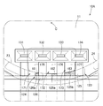
図1(a)及び図2を参照する。モータ用ステータ本体10は、例えば、乗用車のパワーステアリングやコンプレッサ、電動ポンプなどに内蔵される。モータ用ステータ本体10は、積層された多数の電磁鋼板からなるコア11と、このコア11の上側を覆っている第1のインシュレータ20と、コア11の下側を覆っている第2のインシュレータ30と、第1のインシュレータ20及び第2のインシュレータ30に設けられた第1のコイルU1、V1、W1、第2のコイルU2、V2、W2、第3のコイルU3、V3、W3と、第1のインシュレータ20に取り付けられている第1の内部ターミナル15〜第3の内部ターミナル17と、を有している。第1の内部ターミナル15〜第3の内部ターミナル17は、回路基板(不図示)と接続される。このモータ用ステータ本体10は、封止部材により封止される。封止工程については、後述する。
<Example 1>
See FIGS. 1 (a) and 2 (a). The
図2を参照する。コア11は、環状のヨーク12と、ヨーク12から内径方向に延びている9つのティース13と、有している。各々のティース13の先端部13aは、内径方向に向かうに連れて周方向に幅が広がっている。ヨーク12は、外径方向に突出した外縁部12aを有している。
See FIG. The
第1のインシュレータ20は、ヨーク12の上側を覆うことが可能な第1の環状部21と、各々のティース13の上半分を覆うことが可能な9個の第1の巻付け部22と、第1の環状部21の上面21cから軸方向に沿って上方に延出し周方向に断続的に設けられた9個の第1の長壁部23(延出部)と、隣接する第1の長壁部23同士の間に設けられ第1の長壁部23よりも周方向の寸法が短い9個の第1の短壁部24と、を有している。
The
第2のインシュレータ30は、ヨーク12の下側を覆うことが可能な第2の環状部31と、各々のティース13の下側を覆うことが可能な9個の第2の巻付け部32と、第2の環状部31から軸方向に沿って下方に延出している9個の第2の壁部33と、を有している。
The
図1(b)を参照する。9個の第1の長壁部23のなかには、他の第1の長壁部23よりも中心線C方向の寸法が長い、第1の長壁部123が1個設けられている。同様に、9個の第1の短壁部24のなかには、他の第1の短壁部24よりも中心線C方向の寸法が長い、第1の短壁部124が1個設けられている。第1の長壁部123と、第1の短壁部124とは、隣接しており、互いの寸法は等しい。第1の長壁部123及び第1の短壁部124の高さH1は、他の長壁部23及び短壁部24の高さH2よりも高い(H1>H2)。
See FIG. 1 (b). Among the nine first
第1の長壁部123及び第1の短壁部124は、周方向に互いに隣接するヨーク12の外縁部12a、12aの周方向略中央に位置している。
The first
以下、第1のインシュレータ20のなかの、コイルU3の外径側に位置している第1の長壁部23の構成について説明する。
Hereinafter, the configuration of the first
図3(a)を参照する。第1の長壁部23は、周方向に3本の巻線40を案内している第1の案内面51(案内面)と、3本のうち1本の巻線40を内径方向に案内している第2の案内面52と、を有している。第2の案内面52は、第1の案内面51に隣接して巻線40を第1の案内面51から後述する巻付け部90に向けて案内する面である。
See FIG. 3 (a). The first
3本の巻線40のうち、上下2本の巻線40、40は、コイルU1〜コイルW3(図1(a)参照)のなかの、一のコイルから引き出され、他のコイルに向かう際に第1の案内面51に案内されている2本の渡り線41、42である。渡り線41、42の間に位置している巻線40は、コイルU1〜コイルW3のなかの、一のコイルから引き出され、第1の案内面51に案内され、第2の案内面52から内径方向に引き込まれて、コイルU3を構成している巻付け線43である。
Of the three
第1の案内面51の上端51aには、外径方向に突出している第1の突出部60と、第2の突出部70とが設けられている。第1の突出部60の周方向の寸法は、例えば、第1の案内面51の周方向の寸法の3分の1程度である。第1の突出部60と第2の突出部70との間隔は、例えば、第1の案内面51の周方向の寸法の3分の1程度である。なお、突出部の数は、1つでもよく、3つ以上あってもよい。
The
第1の突出部60の下方において、環状部21に第1の溝21aが形成されている。第2の突出部70の下方において、環状部21に第2の溝21bが形成されている。
Below the
図3(a)及び図3(b)を参照する。第1の突出部60は、直方体状の本体部61と、本体部61の外径側の先端61aから下方に延びている凸部62と、を有する。本体部61と凸部62は、一体に形成されている。第1の突出部60の上面60aは、第1の長壁部23の上面23aと、同一面上に位置している。
See FIGS. 3 (a) and 3 (b). The first protruding
第1の突出部60の下面63は、第1の案内面51に案内されている3本の巻線40と当接可能な当接面である。下面63は、第1の長壁部23が延びている上方向に対して、反対方向である下を向いている面である。詳細には、下面63は、上方に膨らむように湾曲している湾曲部64と、この湾曲部64よりも外径側に位置している平面部65と、を有している。
The
湾曲部64は、最上点Pから外径方向に向かうに連れて下方へ下がる外側傾斜部66と、最上点Pから内径方向に向かうに連れて下方へ下がる内側傾斜部67と、を有している。外側傾斜部66は、断面円状の巻線40のなかの、外径側の半円部40aに当接可能な面である。
The
なお、巻線40は、断面形状が円であるものに限られず、断面が多角形のものであってもよい。さらに、湾曲部64は、図3(b)に示されるように、巻線40を両側から挟み込んで保持できる構成であってもよいし、巻線40の両端に接触せずに、巻線40を収容するような構成であってもよい(図示なし)。
The winding 40 is not limited to having a circular cross section, and may have a polygonal cross section. Further, as shown in FIG. 3B, the
さらに、本実施例では、下面63は、湾曲部64と、平面部65との2つの面により構成されているが、例えば、下面63は、第1の案内面51から外径方向に向かうに連れて下方へ下がる1つの平面であってもよい。
Further, in the present embodiment, the
第2の突出部70は、第1の突出部60と同一の大きさ及び形状で構成されており、3本の巻線40と当接可能な下面73を有している。第2の突出部70の他の構成の説明は省略する。第1の突出部60及び第2の突出部70は、図1(a)に示された他の第1の長壁部23にも同様に設けられている。
The second protruding
図4を参照する。次に、コイルU3が設けられている部位について説明する。第1のインシュレータ20の第1の巻付け部22及び第2のインシュレータ30の第2の巻付け部32は、巻付け線43(図3参照)が巻き付けられる巻付け部90を構成している。
See FIG. Next, a portion where the coil U3 is provided will be described. The first winding
第1の巻付け部22と、第2の巻付け部32とは、それぞれ、U字の断面形状を呈している。第1の巻付け部22の開口側の先端22aと、第2の巻付け部32の開口側の先端32aは、互いに対向していると共に、わずかに離れている。
The first winding
なお、実施例では、2つの巻付け部22、32を組み合わせているが、例えば、コア11(図2参照)の形状によっては、ティース13に差し込み可能な単体の巻付け部を構成しても良い。
In the embodiment, the two winding
第1の巻付け部22の上面26と、この上面26の両端から下方に延びている一対の第1の右面27、第1の左面28とは、巻付け線43が接触する面である。同様に、第2の巻付け部32の下面36と、この下面36の両端から上方に延びている一対の第2の右面37、第2の左面38とは、巻付け線43が接触する面である。
The
以下、説明の便宜上、第1の右面27及び第2の右面37を含む面を、第1の巻付け面91(側面)とする。同様に、下面36を、第2の巻付け面92とし、第1の左面28及び第2の左面38を含む面を、第3の巻付け面93(側面)とし、上面26を、第4の巻付け面94(端面)とする。第1の巻付け面91と、第3の巻付け面93は、互いに周方向に反対を向いている。第1の巻付け面92は、下方を向いている。第4の巻付け面94は、上方を向いている。巻付け線43は、第1の巻付け面91〜第4の巻付け面94の順に巻き付けられる。
Hereinafter, for convenience of explanation, the surface including the first
巻付け部90を構成する第1の巻付け面91〜第4の巻付け面94の境界には、それぞれ、巻付け線43の巻き付けを案内することが可能な案内溝95が設けられている。
図4及び図5(a)を参照する。環状部21の内周面21dは、コイルU3の外径側の端部と当接してコイルU3の形状を保持可能な保持面100を有している。この保持面100は、平坦に構成されている。
See FIGS. 4 and 5 (a). The inner
保持面100は、第1の右面27と直交している第1の右保持面101と、第2の右面37と直交している第2の右保持面102と、下面36と直交している下保持面103と、第2の左面38と直交している第2の左保持面104と、第1の左面28と直交している第1の左保持面105と、上面26と直交している上保持面106と、から構成されている。
The holding
上保持面106は、第1の長壁部23の第1の案内面51の反対側の面でもある。第1の右保持面101と、第2の右保持面102とを含む面を右保持面107とする。第1の左保持面105と、第2の左保持面104とを含む面を左保持面108とする。
The
図5(b)を参照する。右保持面107及び第1の巻付け面91(側面)の境界を第1の角111とする。第1の案内面51及び第2の案内面52の境界を第2の角112とする。第1の角111は、第2の角112よりも、時計回り方向側(第1の案内面51による案内方向側、矢印F(図5(a))参照)に位置している。
See FIG. 5 (b). The boundary between the
第2の案内面52は、第1の巻付け面91と平行である。第2の案内面52から第1の巻付け面91までの周方向の寸法Lは、巻付け線43の線径Dに等しい。
The
コイルU3を構成する巻付け線43の巻付けについて説明する。第1の案内面51に沿って時計回りに案内された巻付け線43は、第2の角112を基点にして巻付け部90に向かって内径方向に折り曲げられる。折り曲げられた巻付け線43は、第1の角111に向かって引き込まれ、第1の角111を基点にさらに下方に折り曲げられる。その後、巻付け線43は、第1の巻付け面91〜第4の巻付け面94の順に巻き付けられていく。
The winding of the winding
図6を参照する。モータ用ステータ本体10は、樹脂製の封止部材により封止される。
最初に、封止工程に用いられる金型190について説明する。
See FIG. The
First, the
モータ用ステータ本体10が載置される金型190のキャビティは、円柱状を呈する。金型190の底部191には、底部191から上方に突出した9個の凸部192が周方向に互いに間隔を空けて設けられている。各々の凸部192は、第1のインシュレータ20の内径側の先端部22a(図2参照)を支持可能である。
The cavity of the
さらに、底部191には、金型190の内周面193に沿って、上方に延びる4つの柱部194が周方向に互いに間隔を空けて設けられている。各々の柱部194は、ヨーク12の外縁部12aを支持可能である。
Further, the
さらに、底部191には、封止部材の一部を肉抜きするための第1のピン196〜第3のピン198が設けられている。
Further, the
次に、この金型190によるモータ用ステータ本体10の封止工程を説明する。最初に、金型190の底部191に、第1の外部ターミナル131〜第4の外部ターミナル134を載置する。互いに隣接する第1の外部ターミナル131〜第4の外部ターミナル134の間には、第1のピン196〜第3のピン198が、それぞれ位置する。
Next, the sealing process of the motor stator
次に、第1のピン196〜第3のピン198の先端と、第1のインシュレータ20の第1の長壁部123及び第1の短壁部124とが対向するように、モータ用ステータ本体10を金型190に載置する。その後、金型190のキャビティに樹脂を充填させて封止する。
Next, the
図7を参照する。モータ用ステータ本体10を金型190に載置した時に、第1の長壁部123の先端面125は、第2のピン197、第3のピン198に当接する。第1の短壁部124の先端面126は、第1のピン196に当接する。即ち、金型190にモータ用ステータ本体10を載置すると、モータ用ステータ本体10は、第1のピン196〜第3のピン198に支持される。
See FIG. 7. When the
図8及び図9には、モータ用ステータ本体10が封止部材111により封止されて構成されたモータ用ステータ10Aの一部が示されている。
8 and 9 show a part of the
封止部材111は、互いに隣接する第1の外部ターミナル131〜第4の外部ターミナル134の間に、第1の肉抜き穴171〜第3の肉抜き穴173を有している。第1の肉抜き穴171〜第3の肉抜き穴173は、四角柱状を呈し、モータ用ステータ本体10の中心線Cに沿って延びている。
The sealing
第1の肉抜き穴171は、封止工程の際に第1のピン196(図7参照)が占有していた領域に相当する。第2の肉抜き穴172は、封止工程の際に第2のピン197が占有していた領域に相当する。第3の肉抜き穴173は、封止工程の際に第3のピン198が占有していた領域に相当する。
The
第1の肉抜き穴171の第1の底部175は、一部が貫通しており、第1の貫通穴181を有する。第1の貫通穴181は、第1の短壁部124の先端面126によって塞がれている。
The
同様に、第2の肉抜き穴172の第2の底部176は、一部が貫通しており、第2の貫通穴182を有する。第3の肉抜き穴173の第3の底部177は、一部が貫通しており、第3の貫通穴183を有する。この第2の貫通穴182及び第3の貫通穴183は、第1の長壁部123の先端面125によって塞がれている。
Similarly, the
換言すると、第1の貫通穴181からは、先端面126の一部である露出部126aが露出している。第2の貫通穴182からは、先端面125の一部である露出部125aが露出している。第3の貫通穴183からは、先端面125の一部である露出部125bが露出している。
In other words, the exposed
次に、実施例1の効果について説明する。 Next, the effect of Example 1 will be described.
図10(a)を参照する。比較例のモータ用ステータでは、第1の角201は、第2の角202よりも、反時計回り方向側(矢印R参照)に位置している。そのため、巻線203を巻付け部205に巻き始める際、巻線203は、第2の案内面206と上保持面207との角208に接触する。コイル209を構成する1段目の巻線の巻き始めの部位209aを第1の巻付け面205aに密着させることができず、巻線203と第1の巻付け面205aとの間に隙間CLが生じてしまう。
See FIG. 10 (a). In the motor stator of the comparative example, the
図10(b)を参照する。実施例1のモータ用ステータ本体10では、第1の角111は、第2の角112よりも、時計回り方向側(矢印F参照)に位置している。そのため、巻付け線43を内径方向に引き込み、第2の角112から第1の角111に向けて巻付け線43を延ばす際に、巻付け線43と第1の長壁部23との接触を避けられる。その後、巻付け線43を巻付け部90に巻き始める際、巻付け線43を、右保持面107のみならず、第1の巻付け面91にも接触させることができる。即ち、コイルU3を構成する1段目の巻付け線43の巻き始めの部位を、巻付け部90に対して密着させることができ、1段目の巻付け線43が全体として巻付け部90に確実に巻き付くこととなる。結果として、巻付け線43の占積率が向上する。
See FIG. 10 (b). In the motor stator
図5(b)を参照する。第2の案内面52から第1の巻付け面91までの周方向の寸法Lは、巻付け線43の線径Dに等しい。なお、この寸法Lは、巻付け線43の線径Dの半分より大きく、かつ、巻付け方向についての第4の巻付け面94(端面)の幅(周方向の寸法)Wdの半分から線径Dに相当する分を除いた寸法よりも小さいことが望ましい。このような所定の寸法とすることで、コイルU3から引き出された引出し線44(図3(a)参照)と、巻付け線43とが、干渉することを防げる。
See FIG. 5 (b). The circumferential dimension L from the
<実施例2>
図11(a)及び図11(b)を参照する。次に、実施例2について説明する。実施例1と比較すると、実施例2では、第1の長壁部23Aと、内部ターミナル80が異なる。
<Example 2>
See FIGS. 11 (a) and 11 (b). Next, Example 2 will be described. Compared with the first embodiment, in the second embodiment, the first
第1の長壁部23Aの周方向の寸法は、実施例1の第1の長壁部23の周方向の寸法よりも大きい。具体的には、第1の長壁部23Aの周方向の寸法は、第1のインシュレータ20の環状部21(図2参照)を周方向に9分割した部位の周方向の寸法に略等しい。実施例1と同一の構成については説明を省略し、符号を流用する。
The circumferential dimension of the first
第1の長壁部23Aは、2つの巻線40を周方向に案内している第1の案内面51Aと、第1の案内面51Aの周方向両端から内径方向に延びている第2の案内面52A、第3の案内面53Aと、を有している。第2の案内面52A及び第3の案内面53Aは、巻線40を内径方向に案内する案内面である。
The first
第1の案内面51Aは、第1の突出部60(一方の突出部)と、第2の突出部70(他方の突出部)を有している。第1の案内面51Aに案内されている2本の巻線40のうち、直線状に延びている線を渡り線45とし、一部が湾曲して内部ターミナル80に接続されている線を接続線46とする。
The
内部ターミナル80は、径方向の寸法が薄い薄板状を呈しており、矩形状の本体部81と、本体部81の下部から下方に延びて第1の長壁部23Aの上面23Aaに差し込まれている2本の差込部82と、2本の差込部82の間に位置して本体部61の下部から上方に向かって折り返される折り返し部83と、有している。
The
折り返し部83は、接続線46を挟み込むことにより接続線46と電気的に接続している挟み込み部84(接続部)を有している。接続手法として、例えば、ヒュージングを採用できる。
The folded-
接続線46は、第1の突出部60の下面63と、挟み込み部84と、第2の突出部70の下面73とに当接している。詳細には、接続線46は、第1の突出部60から挟み込み部84の間を斜めに延びている第1の傾斜部47と、挟み込み部84において上面23Aaと平行に延びている平行部48と、折り返し部83の下部から第2の突出部70の間を斜めに延びている第2の傾斜部49と、を有している。
The connecting
挟み込み部84は、第1の突出部60と第2の突出部70との周方向で間に位置しており、第2の突出部70側に寄っている。なお、挟み込み部84は、第1の突出部60と第2の突出部70との間の領域内に位置する場合に限られず、領域の外径側又は内径側にはみでるように位置してもよい。
The sandwiching
なお、本発明の作用及び効果を奏する限りにおいて、本発明は、実施例に限定されるものではない。 The present invention is not limited to the examples as long as the actions and effects of the present invention are exhibited.
10…モータ用ステータ本体(モータ用ステータ)
11…コア
12…ヨーク
20…第1のインシュレータ
21…第1の環状部
23…第1の長壁部(延出部)、23a…先端面
40…巻線
51…第1の案内面
52…第2の案内面
90…巻付け部
91…第1の巻付け面(側面)
94…第4の巻付け面(端面)
100…保持面
107…右保持面
111…第1の角
112…第2の角
D…巻線の線径
Wd…端面の周方向の寸法
U1〜W3…コイル
10 ... Motor stator body (motor stator)
11 ...
94 ... Fourth winding surface (end surface)
100 ... Holding
Claims (2)
前記コアは、環状のヨークと、このヨークから前記モータ用ステータの内径方向に延びているティースと、を有し、
前記インシュレータは、前記ヨークを覆っている環状部と、前記ティースを覆っていると共に前記巻線が巻き付けられている巻付け部と、前記環状部から前記モータ用ステータの軸方向に延出している延出部と、を有し、
前記環状部の内周面は、前記コイルの端部と当接して前記コイルの形状を保持可能な保持面を有しており、
前記延出部は、前記モータ用ステータの周方向に前記巻線を案内する第1の案内面と、この第1の案内面に隣接して前記巻線を前記第1の案内面から前記巻付け部へ向けて案内する第2の案内面と、を有し、
前記巻付け部は、前記第2の案内面と周方向に同じ側の側面と、この側面と直交している端面と、を有しており、
前記モータ用ステータの軸方向から見て、前記保持面及び前記側面の境界に構成された第1の角は、前記第1の案内面及び前記第2の案内面の境界に構成された第2の角よりも、前記第1の案内面による案内方向側に位置しており、
前記巻線は、前記第2の角から前記第1の角へ向かって延びている、ことを特徴とする、モータ用ステータ。 In a motor stator having a core, an insulator covering the core, and a coil composed of windings wound around the insulator.
The core has an annular yoke and a tooth extending from the yoke in the inner diameter direction of the motor stator.
The insulator extends from the annular portion covering the yoke, the winding portion covering the teeth and the winding around the winding portion, and the annular portion in the axial direction of the motor stator. With an extension part,
The inner peripheral surface of the annular portion has a holding surface that is in contact with the end portion of the coil and can hold the shape of the coil.
The extending portion has a first guide surface for guiding the winding in the circumferential direction of the motor stator, and the winding is wound from the first guide surface adjacent to the first guide surface. It has a second guide surface that guides it toward the attachment part,
The winding portion has a side surface on the same side as the second guide surface in the circumferential direction, and an end surface orthogonal to the side surface.
When viewed from the axial direction of the motor stator, the first corner formed at the boundary between the holding surface and the side surface is a second formed at the boundary between the first guide surface and the second guide surface. It is located on the guide direction side by the first guide surface from the corner of.
A stator for a motor, wherein the winding extends from the second corner toward the first corner.
前記第2の案内面から前記側面までの前記周方向の寸法は、前記巻線の線径の半分よりも大きく、かつ、前記端面の周方向の半分の寸法から前記線径に相当する分を除いた寸法よりも小さい、ことを特徴とする請求項1に記載のモータ用ステータ。 The second guide surface is parallel to the side surface of the winding portion.
The circumferential dimension from the second guide surface to the side surface is larger than half the wire diameter of the winding, and the portion corresponding to the wire diameter from the half dimension of the end face in the circumferential direction. The motor stator according to claim 1, wherein the diameter is smaller than the excluded size.
Priority Applications (4)
| Application Number | Priority Date | Filing Date | Title |
|---|---|---|---|
| JP2019060119A JP7258625B2 (en) | 2019-03-27 | 2019-03-27 | motor stator |
| DE102020100368.4A DE102020100368A1 (en) | 2019-03-27 | 2020-01-09 | Stator of a motor |
| US16/744,455 US11171532B2 (en) | 2019-03-27 | 2020-01-16 | Motor stator |
| CN202010106632.1A CN111756152B (en) | 2019-03-27 | 2020-02-21 | Stator for motor |
Applications Claiming Priority (1)
| Application Number | Priority Date | Filing Date | Title |
|---|---|---|---|
| JP2019060119A JP7258625B2 (en) | 2019-03-27 | 2019-03-27 | motor stator |
Publications (2)
| Publication Number | Publication Date |
|---|---|
| JP2020162318A true JP2020162318A (en) | 2020-10-01 |
| JP7258625B2 JP7258625B2 (en) | 2023-04-17 |
Family
ID=72605091
Family Applications (1)
| Application Number | Title | Priority Date | Filing Date |
|---|---|---|---|
| JP2019060119A Active JP7258625B2 (en) | 2019-03-27 | 2019-03-27 | motor stator |
Country Status (4)
| Country | Link |
|---|---|
| US (1) | US11171532B2 (en) |
| JP (1) | JP7258625B2 (en) |
| CN (1) | CN111756152B (en) |
| DE (1) | DE102020100368A1 (en) |
Cited By (1)
| Publication number | Priority date | Publication date | Assignee | Title |
|---|---|---|---|---|
| JP7551107B2 (en) | 2020-11-26 | 2024-09-17 | 多摩川精機株式会社 | Resolver stator winding structure and method |
Families Citing this family (2)
| Publication number | Priority date | Publication date | Assignee | Title |
|---|---|---|---|---|
| WO2019058649A1 (en) * | 2017-09-20 | 2019-03-28 | パナソニックIpマネジメント株式会社 | Insulator, and stator and motor comprising same |
| JP7194625B2 (en) * | 2019-03-27 | 2022-12-22 | 株式会社山田製作所 | motor stator |
Citations (5)
| Publication number | Priority date | Publication date | Assignee | Title |
|---|---|---|---|---|
| JP2002125354A (en) * | 2000-10-13 | 2002-04-26 | Nippon Densan Corp | Magnetic disc driving motor |
| JP2003324886A (en) * | 2002-04-30 | 2003-11-14 | Sankyo Seiki Mfg Co Ltd | Motor and manufacturing method therefor |
| JP2014103712A (en) * | 2012-11-16 | 2014-06-05 | Samsung R&D Institute Japan Co Ltd | Motor |
| JP2015133808A (en) * | 2014-01-10 | 2015-07-23 | アスモ株式会社 | Insulator and stator |
| JP2017034870A (en) * | 2015-08-03 | 2017-02-09 | 多摩川精機株式会社 | Coil protective structure and method for resolver stator |
Family Cites Families (13)
| Publication number | Priority date | Publication date | Assignee | Title |
|---|---|---|---|---|
| JP4868187B2 (en) * | 2009-01-16 | 2012-02-01 | 株式会社富士通ゼネラル | Electric motor |
| JP5453881B2 (en) * | 2009-03-31 | 2014-03-26 | 日本電産株式会社 | motor |
| DE102012224153A1 (en) | 2012-12-21 | 2014-06-26 | Robert Bosch Gmbh | Stator for an electric machine |
| JP5858001B2 (en) | 2013-06-05 | 2016-02-10 | 株式会社デンソー | Motor and fuel pump using the same |
| JP6330333B2 (en) * | 2014-01-14 | 2018-05-30 | 日本電産株式会社 | motor |
| DE102013106999A1 (en) | 2013-07-03 | 2015-01-08 | Ebm-Papst St. Georgen Gmbh & Co. Kg | Electronically commutated motor |
| JP6181002B2 (en) * | 2014-03-20 | 2017-08-16 | 愛三工業株式会社 | Stator and brushless motor |
| JP6462468B2 (en) * | 2015-04-15 | 2019-01-30 | 株式会社ミツバ | Electric motor and method for manufacturing electric motor |
| JP6812975B2 (en) * | 2015-08-10 | 2021-01-13 | 日本電産株式会社 | Motors, motor manufacturing methods, and stator units |
| WO2017138534A1 (en) * | 2016-02-08 | 2017-08-17 | 日本電産株式会社 | Stator, motor, and compressor |
| CN111095740B (en) * | 2017-09-20 | 2022-07-29 | 松下知识产权经营株式会社 | Insulator, stator including the same, and motor including the same |
| JP2019180216A (en) * | 2018-03-30 | 2019-10-17 | 株式会社豊田自動織機 | Stator of rotary electric machine and the rotary electric machine |
| DE102018217852A1 (en) | 2018-10-18 | 2020-04-23 | Bühler Motor GmbH | DC motor and method for manufacturing a DC motor |
-
2019
- 2019-03-27 JP JP2019060119A patent/JP7258625B2/en active Active
-
2020
- 2020-01-09 DE DE102020100368.4A patent/DE102020100368A1/en active Pending
- 2020-01-16 US US16/744,455 patent/US11171532B2/en active Active
- 2020-02-21 CN CN202010106632.1A patent/CN111756152B/en active Active
Patent Citations (5)
| Publication number | Priority date | Publication date | Assignee | Title |
|---|---|---|---|---|
| JP2002125354A (en) * | 2000-10-13 | 2002-04-26 | Nippon Densan Corp | Magnetic disc driving motor |
| JP2003324886A (en) * | 2002-04-30 | 2003-11-14 | Sankyo Seiki Mfg Co Ltd | Motor and manufacturing method therefor |
| JP2014103712A (en) * | 2012-11-16 | 2014-06-05 | Samsung R&D Institute Japan Co Ltd | Motor |
| JP2015133808A (en) * | 2014-01-10 | 2015-07-23 | アスモ株式会社 | Insulator and stator |
| JP2017034870A (en) * | 2015-08-03 | 2017-02-09 | 多摩川精機株式会社 | Coil protective structure and method for resolver stator |
Cited By (1)
| Publication number | Priority date | Publication date | Assignee | Title |
|---|---|---|---|---|
| JP7551107B2 (en) | 2020-11-26 | 2024-09-17 | 多摩川精機株式会社 | Resolver stator winding structure and method |
Also Published As
| Publication number | Publication date |
|---|---|
| DE102020100368A1 (en) | 2020-10-01 |
| JP7258625B2 (en) | 2023-04-17 |
| US20200313492A1 (en) | 2020-10-01 |
| CN111756152B (en) | 2024-04-02 |
| US11171532B2 (en) | 2021-11-09 |
| CN111756152A (en) | 2020-10-09 |
Similar Documents
| Publication | Publication Date | Title |
|---|---|---|
| JP5306411B2 (en) | Rotating electric machine | |
| CN100543890C (en) | Transformer | |
| JP4655764B2 (en) | Rotating electric machine | |
| KR101993622B1 (en) | Motor, method of manufacturing motor, and stator unit | |
| JP2020162316A (en) | Stator for motor | |
| JP2020162318A (en) | Stator for motor | |
| US20210320539A1 (en) | Motor | |
| US9712014B2 (en) | Insulator, stator assembly, rotating electrical machine, and connection board | |
| JP2009089584A (en) | Motor | |
| JP2018133866A (en) | Motor and pump device | |
| KR20220007449A (en) | Bus bar unit for motor | |
| JP7037868B2 (en) | Motor stator | |
| JP5666976B2 (en) | Rotating electric machine | |
| JP5813359B2 (en) | Rotating electric machine | |
| JP2013243800A (en) | Rotary electric machine | |
| JP2012253979A (en) | Rotary electric machine and method for manufacturing the same | |
| JP2016093055A (en) | Stator core assembly | |
| JP2002272050A (en) | Resolver stator structure | |
| JP2006191703A (en) | Stator core of motor | |
| JP6739497B2 (en) | Rotating machine armature | |
| JP2009089493A (en) | Motor | |
| JP2003088031A (en) | Stator for capacitor motor | |
| JP2007221882A (en) | Core module and bobbin of stator | |
| JP2013005634A (en) | Outer rotor type motor | |
| JP2020162300A (en) | Rotary electric machine |
Legal Events
| Date | Code | Title | Description |
|---|---|---|---|
| A621 | Written request for application examination |
Free format text: JAPANESE INTERMEDIATE CODE: A621 Effective date: 20211207 |
|
| A977 | Report on retrieval |
Free format text: JAPANESE INTERMEDIATE CODE: A971007 Effective date: 20220908 |
|
| A131 | Notification of reasons for refusal |
Free format text: JAPANESE INTERMEDIATE CODE: A131 Effective date: 20221004 |
|
| A521 | Request for written amendment filed |
Free format text: JAPANESE INTERMEDIATE CODE: A523 Effective date: 20221124 |
|
| TRDD | Decision of grant or rejection written | ||
| A01 | Written decision to grant a patent or to grant a registration (utility model) |
Free format text: JAPANESE INTERMEDIATE CODE: A01 Effective date: 20230322 |
|
| A61 | First payment of annual fees (during grant procedure) |
Free format text: JAPANESE INTERMEDIATE CODE: A61 Effective date: 20230405 |
|
| R150 | Certificate of patent or registration of utility model |
Ref document number: 7258625 Country of ref document: JP Free format text: JAPANESE INTERMEDIATE CODE: R150 |