JP2017533548A - Electrochemical cell having semi-solid electrode and method for producing the same - Google Patents
Electrochemical cell having semi-solid electrode and method for producing the same Download PDFInfo
- Publication number
- JP2017533548A JP2017533548A JP2017517309A JP2017517309A JP2017533548A JP 2017533548 A JP2017533548 A JP 2017533548A JP 2017517309 A JP2017517309 A JP 2017517309A JP 2017517309 A JP2017517309 A JP 2017517309A JP 2017533548 A JP2017533548 A JP 2017533548A
- Authority
- JP
- Japan
- Prior art keywords
- current collector
- semi
- electrochemical cell
- solid
- cathode
- Prior art date
- Legal status (The legal status is an assumption and is not a legal conclusion. Google has not performed a legal analysis and makes no representation as to the accuracy of the status listed.)
- Pending
Links
Images


Classifications
-
- H—ELECTRICITY
- H01—ELECTRIC ELEMENTS
- H01M—PROCESSES OR MEANS, e.g. BATTERIES, FOR THE DIRECT CONVERSION OF CHEMICAL ENERGY INTO ELECTRICAL ENERGY
- H01M4/00—Electrodes
- H01M4/02—Electrodes composed of, or comprising, active material
-
- H—ELECTRICITY
- H01—ELECTRIC ELEMENTS
- H01M—PROCESSES OR MEANS, e.g. BATTERIES, FOR THE DIRECT CONVERSION OF CHEMICAL ENERGY INTO ELECTRICAL ENERGY
- H01M10/00—Secondary cells; Manufacture thereof
- H01M10/04—Construction or manufacture in general
- H01M10/0413—Large-sized flat cells or batteries for motive or stationary systems with plate-like electrodes
-
- H—ELECTRICITY
- H01—ELECTRIC ELEMENTS
- H01M—PROCESSES OR MEANS, e.g. BATTERIES, FOR THE DIRECT CONVERSION OF CHEMICAL ENERGY INTO ELECTRICAL ENERGY
- H01M10/00—Secondary cells; Manufacture thereof
- H01M10/04—Construction or manufacture in general
- H01M10/0436—Small-sized flat cells or batteries for portable equipment
-
- H—ELECTRICITY
- H01—ELECTRIC ELEMENTS
- H01M—PROCESSES OR MEANS, e.g. BATTERIES, FOR THE DIRECT CONVERSION OF CHEMICAL ENERGY INTO ELECTRICAL ENERGY
- H01M10/00—Secondary cells; Manufacture thereof
- H01M10/04—Construction or manufacture in general
- H01M10/049—Processes for forming or storing electrodes in the battery container
-
- H—ELECTRICITY
- H01—ELECTRIC ELEMENTS
- H01M—PROCESSES OR MEANS, e.g. BATTERIES, FOR THE DIRECT CONVERSION OF CHEMICAL ENERGY INTO ELECTRICAL ENERGY
- H01M10/00—Secondary cells; Manufacture thereof
- H01M10/05—Accumulators with non-aqueous electrolyte
- H01M10/052—Li-accumulators
- H01M10/0525—Rocking-chair batteries, i.e. batteries with lithium insertion or intercalation in both electrodes; Lithium-ion batteries
-
- H—ELECTRICITY
- H01—ELECTRIC ELEMENTS
- H01M—PROCESSES OR MEANS, e.g. BATTERIES, FOR THE DIRECT CONVERSION OF CHEMICAL ENERGY INTO ELECTRICAL ENERGY
- H01M10/00—Secondary cells; Manufacture thereof
- H01M10/05—Accumulators with non-aqueous electrolyte
- H01M10/058—Construction or manufacture
- H01M10/0585—Construction or manufacture of accumulators having only flat construction elements, i.e. flat positive electrodes, flat negative electrodes and flat separators
-
- H—ELECTRICITY
- H01—ELECTRIC ELEMENTS
- H01M—PROCESSES OR MEANS, e.g. BATTERIES, FOR THE DIRECT CONVERSION OF CHEMICAL ENERGY INTO ELECTRICAL ENERGY
- H01M4/00—Electrodes
- H01M4/02—Electrodes composed of, or comprising, active material
- H01M4/04—Processes of manufacture in general
- H01M4/0402—Methods of deposition of the material
- H01M4/0404—Methods of deposition of the material by coating on electrode collectors
-
- H—ELECTRICITY
- H01—ELECTRIC ELEMENTS
- H01M—PROCESSES OR MEANS, e.g. BATTERIES, FOR THE DIRECT CONVERSION OF CHEMICAL ENERGY INTO ELECTRICAL ENERGY
- H01M4/00—Electrodes
- H01M4/02—Electrodes composed of, or comprising, active material
- H01M4/04—Processes of manufacture in general
- H01M4/0402—Methods of deposition of the material
- H01M4/0407—Methods of deposition of the material by coating on an electrolyte layer
-
- H—ELECTRICITY
- H01—ELECTRIC ELEMENTS
- H01M—PROCESSES OR MEANS, e.g. BATTERIES, FOR THE DIRECT CONVERSION OF CHEMICAL ENERGY INTO ELECTRICAL ENERGY
- H01M4/00—Electrodes
- H01M4/02—Electrodes composed of, or comprising, active material
- H01M4/04—Processes of manufacture in general
- H01M4/0402—Methods of deposition of the material
- H01M4/0409—Methods of deposition of the material by a doctor blade method, slip-casting or roller coating
-
- H—ELECTRICITY
- H01—ELECTRIC ELEMENTS
- H01M—PROCESSES OR MEANS, e.g. BATTERIES, FOR THE DIRECT CONVERSION OF CHEMICAL ENERGY INTO ELECTRICAL ENERGY
- H01M4/00—Electrodes
- H01M4/02—Electrodes composed of, or comprising, active material
- H01M4/04—Processes of manufacture in general
- H01M4/0473—Filling tube-or pockets type electrodes; Applying active mass in cup-shaped terminals
-
- H—ELECTRICITY
- H01—ELECTRIC ELEMENTS
- H01M—PROCESSES OR MEANS, e.g. BATTERIES, FOR THE DIRECT CONVERSION OF CHEMICAL ENERGY INTO ELECTRICAL ENERGY
- H01M4/00—Electrodes
- H01M4/02—Electrodes composed of, or comprising, active material
- H01M4/13—Electrodes for accumulators with non-aqueous electrolyte, e.g. for lithium-accumulators; Processes of manufacture thereof
-
- H—ELECTRICITY
- H01—ELECTRIC ELEMENTS
- H01M—PROCESSES OR MEANS, e.g. BATTERIES, FOR THE DIRECT CONVERSION OF CHEMICAL ENERGY INTO ELECTRICAL ENERGY
- H01M4/00—Electrodes
- H01M4/02—Electrodes composed of, or comprising, active material
- H01M4/36—Selection of substances as active materials, active masses, active liquids
-
- H—ELECTRICITY
- H01—ELECTRIC ELEMENTS
- H01M—PROCESSES OR MEANS, e.g. BATTERIES, FOR THE DIRECT CONVERSION OF CHEMICAL ENERGY INTO ELECTRICAL ENERGY
- H01M4/00—Electrodes
- H01M4/02—Electrodes composed of, or comprising, active material
- H01M4/64—Carriers or collectors
- H01M4/66—Selection of materials
- H01M4/661—Metal or alloys, e.g. alloy coatings
-
- H—ELECTRICITY
- H01—ELECTRIC ELEMENTS
- H01M—PROCESSES OR MEANS, e.g. BATTERIES, FOR THE DIRECT CONVERSION OF CHEMICAL ENERGY INTO ELECTRICAL ENERGY
- H01M4/00—Electrodes
- H01M4/02—Electrodes composed of, or comprising, active material
- H01M4/64—Carriers or collectors
- H01M4/70—Carriers or collectors characterised by shape or form
-
- H—ELECTRICITY
- H01—ELECTRIC ELEMENTS
- H01M—PROCESSES OR MEANS, e.g. BATTERIES, FOR THE DIRECT CONVERSION OF CHEMICAL ENERGY INTO ELECTRICAL ENERGY
- H01M50/00—Constructional details or processes of manufacture of the non-active parts of electrochemical cells other than fuel cells, e.g. hybrid cells
- H01M50/10—Primary casings; Jackets or wrappings
- H01M50/102—Primary casings; Jackets or wrappings characterised by their shape or physical structure
- H01M50/105—Pouches or flexible bags
-
- H—ELECTRICITY
- H01—ELECTRIC ELEMENTS
- H01M—PROCESSES OR MEANS, e.g. BATTERIES, FOR THE DIRECT CONVERSION OF CHEMICAL ENERGY INTO ELECTRICAL ENERGY
- H01M50/00—Constructional details or processes of manufacture of the non-active parts of electrochemical cells other than fuel cells, e.g. hybrid cells
- H01M50/40—Separators; Membranes; Diaphragms; Spacing elements inside cells
- H01M50/46—Separators, membranes or diaphragms characterised by their combination with electrodes
-
- H—ELECTRICITY
- H01—ELECTRIC ELEMENTS
- H01M—PROCESSES OR MEANS, e.g. BATTERIES, FOR THE DIRECT CONVERSION OF CHEMICAL ENERGY INTO ELECTRICAL ENERGY
- H01M50/00—Constructional details or processes of manufacture of the non-active parts of electrochemical cells other than fuel cells, e.g. hybrid cells
- H01M50/50—Current conducting connections for cells or batteries
- H01M50/543—Terminals
- H01M50/552—Terminals characterised by their shape
- H01M50/553—Terminals adapted for prismatic, pouch or rectangular cells
- H01M50/557—Plate-shaped terminals
-
- H—ELECTRICITY
- H01—ELECTRIC ELEMENTS
- H01M—PROCESSES OR MEANS, e.g. BATTERIES, FOR THE DIRECT CONVERSION OF CHEMICAL ENERGY INTO ELECTRICAL ENERGY
- H01M4/00—Electrodes
- H01M4/02—Electrodes composed of, or comprising, active material
- H01M2004/021—Physical characteristics, e.g. porosity, surface area
-
- H—ELECTRICITY
- H01—ELECTRIC ELEMENTS
- H01M—PROCESSES OR MEANS, e.g. BATTERIES, FOR THE DIRECT CONVERSION OF CHEMICAL ENERGY INTO ELECTRICAL ENERGY
- H01M4/00—Electrodes
- H01M4/02—Electrodes composed of, or comprising, active material
- H01M2004/023—Gel electrode
-
- H—ELECTRICITY
- H01—ELECTRIC ELEMENTS
- H01M—PROCESSES OR MEANS, e.g. BATTERIES, FOR THE DIRECT CONVERSION OF CHEMICAL ENERGY INTO ELECTRICAL ENERGY
- H01M4/00—Electrodes
- H01M4/02—Electrodes composed of, or comprising, active material
- H01M2004/026—Electrodes composed of, or comprising, active material characterised by the polarity
- H01M2004/029—Bipolar electrodes
-
- H—ELECTRICITY
- H01—ELECTRIC ELEMENTS
- H01M—PROCESSES OR MEANS, e.g. BATTERIES, FOR THE DIRECT CONVERSION OF CHEMICAL ENERGY INTO ELECTRICAL ENERGY
- H01M2220/00—Batteries for particular applications
- H01M2220/30—Batteries in portable systems, e.g. mobile phone, laptop
-
- H—ELECTRICITY
- H01—ELECTRIC ELEMENTS
- H01M—PROCESSES OR MEANS, e.g. BATTERIES, FOR THE DIRECT CONVERSION OF CHEMICAL ENERGY INTO ELECTRICAL ENERGY
- H01M4/00—Electrodes
- H01M4/02—Electrodes composed of, or comprising, active material
- H01M4/13—Electrodes for accumulators with non-aqueous electrolyte, e.g. for lithium-accumulators; Processes of manufacture thereof
- H01M4/139—Processes of manufacture
-
- H—ELECTRICITY
- H01—ELECTRIC ELEMENTS
- H01M—PROCESSES OR MEANS, e.g. BATTERIES, FOR THE DIRECT CONVERSION OF CHEMICAL ENERGY INTO ELECTRICAL ENERGY
- H01M50/00—Constructional details or processes of manufacture of the non-active parts of electrochemical cells other than fuel cells, e.g. hybrid cells
- H01M50/10—Primary casings; Jackets or wrappings
- H01M50/183—Sealing members
-
- Y—GENERAL TAGGING OF NEW TECHNOLOGICAL DEVELOPMENTS; GENERAL TAGGING OF CROSS-SECTIONAL TECHNOLOGIES SPANNING OVER SEVERAL SECTIONS OF THE IPC; TECHNICAL SUBJECTS COVERED BY FORMER USPC CROSS-REFERENCE ART COLLECTIONS [XRACs] AND DIGESTS
- Y02—TECHNOLOGIES OR APPLICATIONS FOR MITIGATION OR ADAPTATION AGAINST CLIMATE CHANGE
- Y02E—REDUCTION OF GREENHOUSE GAS [GHG] EMISSIONS, RELATED TO ENERGY GENERATION, TRANSMISSION OR DISTRIBUTION
- Y02E60/00—Enabling technologies; Technologies with a potential or indirect contribution to GHG emissions mitigation
- Y02E60/10—Energy storage using batteries
-
- Y—GENERAL TAGGING OF NEW TECHNOLOGICAL DEVELOPMENTS; GENERAL TAGGING OF CROSS-SECTIONAL TECHNOLOGIES SPANNING OVER SEVERAL SECTIONS OF THE IPC; TECHNICAL SUBJECTS COVERED BY FORMER USPC CROSS-REFERENCE ART COLLECTIONS [XRACs] AND DIGESTS
- Y02—TECHNOLOGIES OR APPLICATIONS FOR MITIGATION OR ADAPTATION AGAINST CLIMATE CHANGE
- Y02P—CLIMATE CHANGE MITIGATION TECHNOLOGIES IN THE PRODUCTION OR PROCESSING OF GOODS
- Y02P70/00—Climate change mitigation technologies in the production process for final industrial or consumer products
- Y02P70/50—Manufacturing or production processes characterised by the final manufactured product
Landscapes
- Chemical & Material Sciences (AREA)
- Chemical Kinetics & Catalysis (AREA)
- Electrochemistry (AREA)
- General Chemical & Material Sciences (AREA)
- Engineering & Computer Science (AREA)
- Manufacturing & Machinery (AREA)
- Materials Engineering (AREA)
- Secondary Cells (AREA)
- Battery Electrode And Active Subsutance (AREA)
- Cell Electrode Carriers And Collectors (AREA)
- Sealing Battery Cases Or Jackets (AREA)
- Electric Double-Layer Capacitors Or The Like (AREA)
Abstract
本明細書に記載されている実施形態は、概して、集電体の片面だけに被覆された半固体電極を有する電気化学セルに関する。いくつかの実施形態では、電気化学セルは、正の集電体の片面だけに被覆された半固体正極と、負の集電体の片面だけに被覆された半固体負極と、を含む。セパレータが、半固体正極と半固体負極との間に配置されている。半固体正極および半固体負極の少なくとも1つは、少なくとも約250μmの厚さを有することができる。Embodiments described herein generally relate to an electrochemical cell having a semi-solid electrode coated on only one side of a current collector. In some embodiments, the electrochemical cell includes a semi-solid positive electrode coated on only one side of the positive current collector and a semi-solid negative electrode coated only on one side of the negative current collector. A separator is disposed between the semisolid positive electrode and the semisolid negative electrode. At least one of the semi-solid positive electrode and the semi-solid negative electrode can have a thickness of at least about 250 μm.
Description
関連出願の相互参照
本出願は、2014年11月5日出願の「半固体電極を有する電気化学セルおよびその製造方法(Electrochemical Cells Having Semi-Solid Electrodes and Methods of Manufacturing the Same)」という名称の米国仮特許出願第62/075,373号の優先権および利益を主張し、その開示内容全体が参照により本明細書に組み込まれている。
CROSS REFERENCE TO RELATED APPLICATIONS This application is a United States application entitled “Electrochemical Cells Having Semi-Solid Electrodes and Methods of Manufacturing the Same” filed November 5, 2014. The priority and benefit of provisional patent application No. 62 / 075,373 is claimed, the entire disclosure of which is incorporated herein by reference.
背景
本明細書に記載されている諸実施形態は、概して、集電体の片面だけに被覆された半固体電極を有する電気化学セル、このような電気化学セルのスタック、およびこのような電気化学セルスタックの形成方法に関する。
BACKGROUND Embodiments described herein generally relate to electrochemical cells having semi-solid electrodes coated on only one side of a current collector, stacks of such electrochemical cells, and such electrochemicals. The present invention relates to a method for forming a cell stack.
バッテリは通常、固体電極、セパレータ、電解質、および付属的構成要素、例えば、パッケージング、熱管理、セル平衡、電流キャリアの端子への統合、および/または他のこのような構成要素で構成されている。電極は通常、活物質、導電材料、結合剤および他の添加剤を含む。 A battery is usually composed of solid electrodes, separators, electrolytes, and ancillary components such as packaging, thermal management, cell balancing, integration of current carriers into terminals, and / or other such components. Yes. The electrode typically includes an active material, a conductive material, a binder, and other additives.
バッテリを調製するための既知のいくつかの方法は、金属基板(例えば、集電体)を、溶媒中に溶解または分散している活物質、導電性添加剤、および結合剤からなるスラリーで被覆するステップと、溶媒を蒸発させるステップと、乾燥した固体マトリクスを指定の厚さまでカレンダリングするステップと、を含む。次に、電極が切断され、他の構成要素とともにパッケージングされ、電解質を浸透させた後、パッケージ全体が密封される。 Some known methods for preparing batteries include coating a metal substrate (eg, a current collector) with a slurry consisting of an active material, a conductive additive, and a binder dissolved or dispersed in a solvent. And evaporating the solvent, and calendering the dried solid matrix to a specified thickness. The electrode is then cut and packaged with other components, and after allowing the electrolyte to penetrate, the entire package is sealed.
このような既知の方法は、概して、電極のキャスティングなどの複雑かつ費用のかかる製造ステップを伴い、例えば(最終片面被覆厚さ)100μm未満の、厚さの限定された電極にのみ適切である。厚さの限定された電極を生産するためのこれらの既知の方法では、バッテリは結果として、容量が小さくなり、エネルギー密度が低くなり、活物質に対する不活性構成要素の比率が高くなる。さらに、既知の電極配合物で用いられる結合剤は、ねじれを増加させ、電極のイオン導電率を低下させる可能性がある。 Such known methods generally involve complex and expensive manufacturing steps such as electrode casting, and are only suitable for limited thickness electrodes, for example (final single-sided coating thickness) less than 100 μm. In these known methods for producing electrodes of limited thickness, the battery results in a smaller capacity, lower energy density, and a higher ratio of inert components to active material. In addition, the binders used in known electrode formulations can increase twist and reduce the ionic conductivity of the electrode.
不活性物質に対する活物質の比率を高めるために、従来の電気化学セルは、概して、電極活物質(すなわち、アノード配合物スラリーおよびカソード配合物スラリー)を集電体の両面に被覆することにより形成されている。セパレータが、電極間、すなわちアノードとカソードとの間に配置され、従来の電気化学セルを形成している。複数のこのような電気化学セルは、一般的にはスペーサを間に挟んで、互いに積層され、電気化学セルスタックを形成することができる。これは、不活性物質に対する活物質の比率にプラスの影響を及ぼすが、製造プロセスが複雑になってしまう。さらに、電気化学バッテリを組み立てるのにかなりの時間を要する場合がある。これにより、電極材料の温度変動または湿気への露出が増え、電極材料が劣化することで、電極の電子物性が劣化するおそれがある。 In order to increase the ratio of active material to inert material, conventional electrochemical cells are generally formed by coating electrode active materials (ie, anode formulation slurry and cathode formulation slurry) on both sides of the current collector. Has been. A separator is disposed between the electrodes, i.e., between the anode and the cathode, forming a conventional electrochemical cell. A plurality of such electrochemical cells can generally be stacked together with a spacer in between to form an electrochemical cell stack. This has a positive effect on the ratio of active material to inert material, but complicates the manufacturing process. Furthermore, it may take a considerable amount of time to assemble the electrochemical battery. As a result, the temperature fluctuation of the electrode material or the exposure to moisture increases, and the electrode material deteriorates, so that the electronic physical properties of the electrode may deteriorate.
したがって、サイクル寿命が長く、エネルギー密度、電荷容量および全体的な性能が向上した、新たな電気化学バッテリおよび電極の開発が、エネルギー貯蔵システム開発の永続的な目標である。 Thus, the development of new electrochemical batteries and electrodes with long cycle life, improved energy density, charge capacity and overall performance is a permanent goal of energy storage system development.
本明細書に記載されている諸実施形態は、概して、集電体の片面だけに被覆された半固体電極を有する電気化学セルに関する。いくつかの実施形態では、電気化学セルは、正の集電体の片面だけに被覆された半固体正極と、負の集電体の片面だけに被覆された半固体負極と、を含む。セパレータが、半固体正極と半固体負極との間に配置されている。半固体正極および半固体負極の少なくとも1つは、少なくとも約250μmの厚さを有することができる。 The embodiments described herein generally relate to an electrochemical cell having a semi-solid electrode coated on only one side of a current collector. In some embodiments, the electrochemical cell includes a semi-solid positive electrode coated on only one side of the positive current collector and a semi-solid negative electrode coated only on one side of the negative current collector. A separator is disposed between the semisolid positive electrode and the semisolid negative electrode. At least one of the semi-solid positive electrode and the semi-solid negative electrode can have a thickness of at least about 250 μm.
詳細な説明
家電用バッテリは、リチウムイオンバッテリ技術の進歩とともにエネルギー密度が徐々に増加している。製造されるバッテリの貯蔵エネルギーまたは電荷容量は、(1)活物質の固有電荷容量(mAh/g)、(2)電極の容積(cm3)(すなわち、電極の厚さ、電極面積、および層(スタック)の数の積)、および(3)電極媒体中の活物質の投入量(例えば、電極媒体のcm3当たりの活物質のグラム数)の関数である。したがって、商業的な訴求力(例えば、エネルギー密度の増加およびコストの減少)を高めるためには、概して、面積電荷容量(mAh/cm2)を増加させることが望ましい。面積電荷容量は、例えば、より大きい固有電荷容量を有する活物質を使用すること、電極配合物全体における活性電荷蓄積材料の相対的割合(すなわち、「投入量」)を増加すること、および/または任意の所与のバッテリ形状因子に使用される電極材料の相対的割合を増加することにより、増加させることができる。別の言い方をすると、不活性構成要素(例えば、セパレータおよび集電体)に対する活性電荷蓄積構成要素(例えば、電極)の比率を増加することにより、バッテリの全体的な性能に寄与しない構成要素を取り除くか、または減らすことでバッテリの全体的なエネルギー密度を増加させる。面積電荷容量の増加、したがって、不活性構成要素の相対的割合の減少を達成するための1つの方法は、電極の厚さを大きくすることである。
DETAILED DESCRIPTION Consumer batteries are gradually increasing in energy density with advances in lithium ion battery technology. The storage energy or charge capacity of the battery to be produced is: (1) the intrinsic charge capacity of the active material (mAh / g), (2) the volume of the electrode (cm 3 ) (ie, electrode thickness, electrode area, and layer) (Product of the number of (stacks)), and (3) a function of the input amount of active material in the electrode medium (eg, grams of active material per cm 3 of electrode medium). Thus, it is generally desirable to increase the area charge capacity (mAh / cm 2 ) to increase commercial appeal (eg, increased energy density and reduced cost). Area charge capacity, for example, using an active material with a larger intrinsic charge capacity, increasing the relative proportion of active charge storage material (ie, “input”) in the overall electrode formulation, and / or This can be increased by increasing the relative proportion of electrode material used for any given battery form factor. In other words, by increasing the ratio of active charge storage components (eg, electrodes) to inactive components (eg, separators and current collectors), components that do not contribute to the overall performance of the battery. Remove or reduce the overall energy density of the battery. One way to achieve an increase in area charge capacity and thus a decrease in the relative proportion of inactive components is to increase the electrode thickness.
本明細書に記載されている半固体電極は、(i)ねじれが低減され、半固体電極の電子導電率が大きくなることにより、(例えば、250μmよりも大きく、2,000μm以上まで)厚くすることが可能であり、(ii)活物質の投入量を大きくすることが可能であり、かつ、(iii)使用する機器が少なくなり、製造プロセスを単純化することが可能である。これらの半固体電極は、固定された構成または流動可能な構成で形成することが可能であり、活性構成要素に対する不活性構成要素の容積、質量、およびコストの寄与を小さくすることで、半固体電極を用いて作られるバッテリの商業的な訴求力を高めることができる。いくつかの実施形態では、本明細書に記載されている半固体電極は、従来のバッテリ製造に使用される結合剤が無いか、もしくは結合剤を用いないか、またはその両方である。その代わりに、従来の電極では通常は結合剤によって占有される電極の容積が、ここでは、1)ねじれを減少させ、イオン拡散に使用可能な塩の総量を増加させることで、高速での使用時に厚い従来の電極によく見られる塩枯渇効果に対処する効果を有する電解質、2)バッテリの電荷容量を増やす効果を有する活物質、または、3)電極の電子導電率を上昇させることで、厚い従来の電極の高い内部インピーダンスに対処する効果を有する導電性添加剤によって、占有されることになる。本明細書に記載されている半固体電極のねじれが減少し、電子導電率が上昇する結果、半固体電極から形成された電気化学セルの速度能力および電荷容量が優れたものとなる。 The semi-solid electrodes described herein are (i) thickened (eg, greater than 250 μm and up to 2,000 μm or more) by reducing twist and increasing the electronic conductivity of the semi-solid electrode. (Ii) it is possible to increase the input amount of the active material, and (iii) it is possible to reduce the number of devices used and simplify the manufacturing process. These semi-solid electrodes can be formed in a fixed configuration or a flowable configuration, and reduce the volume, mass, and cost contribution of the inert component to the active component, resulting in a semi-solid The commercial appeal of batteries made using electrodes can be increased. In some embodiments, the semi-solid electrodes described herein are free of binders used in conventional battery manufacturing, or no binders, or both. Instead, the volume of the electrode normally occupied by the binder in conventional electrodes, where 1) is used at high speeds by reducing twist and increasing the total amount of salt available for ion diffusion An electrolyte that has the effect of addressing the salt depletion effect often found in thick conventional electrodes, 2) an active material that has the effect of increasing the charge capacity of the battery, or 3) it is thick by increasing the electronic conductivity of the electrode It will be occupied by conductive additives that have the effect of addressing the high internal impedance of conventional electrodes. As a result of the reduced twist and semi-solid electrode conductivity described herein, the rate capability and charge capacity of electrochemical cells formed from semi-solid electrodes are superior.
本明細書に記載されている半固体電極は、従来の電極よりも大幅に厚くすることが可能であるため、不活性材料(すなわち集電体およびセパレータ)に対する活物質(すなわち半固体カソードおよび/またはアノード)の比率は、従来の電極を含む電気化学セルスタックから形成される同様のバッテリに比べて、半固体電極を含む電気化学セルスタックから形成されるバッテリでは、かなり高くなり得る。これにより、本明細書に記載されている半固体電極を含むバッテリの電荷容量およびエネルギー密度全体が、大幅に増加する。厚い半固体電極およびその様々な配合物を利用する電気化学セルの例が、2015年3月31日発行の、「高速度能力を有する半固体電極(Semi-Solid Electrodes Having High Rate Capability)」という名称の米国特許第8,993,159号(「‘159号特許」とも呼ばれる)、2014年3月10日出願の、「半固体カソードおよび高エネルギー密度アノードを有する非対称型電池(Asymmetric Battery Having a Semi-Solid Cathode and High Energy Density Anode)」という名称の米国特許出願公開第2014/0315097号(「‘097号公開」とも呼ばれる)、および、2014年7月21日出願の、「ゲルポリマー添加剤を用いた半固体電極(Semi-Solid Electrodes with Gel Polymer Additive)」という名称の米国特許出願公開第2015/0024279号(「‘279号公開」とも呼ばれる)に記載されており、その開示内容全体が参照により本明細書に組み込まれている。 Since the semi-solid electrodes described herein can be significantly thicker than conventional electrodes, the active material (ie, the semi-solid cathode and / or the semi-solid cathode and / or the separator) is inert. Or anode) ratio can be significantly higher for batteries formed from electrochemical cell stacks comprising semi-solid electrodes compared to similar batteries formed from electrochemical cell stacks comprising conventional electrodes. This greatly increases the overall charge capacity and energy density of the battery including the semi-solid electrode described herein. An example of an electrochemical cell utilizing a thick semi-solid electrode and its various formulations is called “Semi-Solid Electrodes Having High Rate Capability” published on March 31, 2015. US Pat. No. 8,993,159 (also referred to as “the '159 patent”), entitled “Asymmetric Battery Having a Semi-Solid Cathode and High Energy Density Anode, filed Mar. 10, 2014 US Patent Application Publication No. 2014/0315097 (also called “'097 Publication”) named “Semi-Solid Cathode and High Energy Density Anode”, and “Gel Polymer Additive” filed on July 21, 2014 US Patent Application Publication No. 2015/0024279 (“Publication of '279”) entitled “Semi-Solid Electrodes with Gel Polymer Additive” (Also referred to as “open”), the entire disclosure of which is incorporated herein by reference.
本明細書に記載されている半固体電極は、スラリーとして配合され、電解質がスラリー配合物に含まれるようになっている。これは、電気化学セルが容器、例えばパウチまたは缶に配置されると、通常電解質が電気化学セルに添加される従来の電極、例えばカレンダリングされた電極とは対照的である。半固体電極の周囲環境への露出時間が長くなることにより電解質の蒸発が増加することで、電気化学セルの物理的特性(例えば流動性)および/または電子特性(例えば導電率、電荷容量、エネルギー密度など)に影響する場合がある。さらにまた、周囲環境の湿気が、電解質の性能に悪影響をもたらす場合もある。したがって、本明細書に記載されている半固体電極を含む電気化学セルを最短時間で組み立て、電解質の蒸発および/または劣化を抑えることが得策であろう。しかしながら、一部の事例では、集電体(例えば、金属箔)の両面に半固体電極を配置することは、かなり時間がかかる場合がある。さらにまた、このような電気化学セルから電気化学セルスタックを形成するには、隣接した電気化学セル間にスペーサを配置する場合が多く、電気化学セルに含まれる半固体電極が周囲大気に露出される時間がさらに長くなる場合がある。 The semi-solid electrode described herein is formulated as a slurry so that an electrolyte is included in the slurry formulation. This is in contrast to conventional electrodes, such as calendered electrodes, where an electrolyte is usually added to the electrochemical cell when the electrochemical cell is placed in a container, such as a pouch or can. Increasing electrolyte evaporation due to longer exposure time of the semi-solid electrode to the surrounding environment results in the physical (eg, fluidity) and / or electronic properties (eg, conductivity, charge capacity, energy) of the electrochemical cell. Density). Furthermore, ambient humidity may adversely affect the performance of the electrolyte. Thus, it would be advantageous to assemble an electrochemical cell including the semi-solid electrode described herein in the shortest time to reduce electrolyte evaporation and / or degradation. However, in some cases, placing semi-solid electrodes on both sides of a current collector (eg, a metal foil) can be quite time consuming. Furthermore, in order to form an electrochemical cell stack from such an electrochemical cell, a spacer is often disposed between adjacent electrochemical cells, and the semi-solid electrode contained in the electrochemical cell is exposed to the surrounding atmosphere. May take longer.
本明細書に記載されている電気化学セルの諸実施形態は、集電体の片面だけに被覆された半固体電極を含む。集電体の片面だけを被覆することにより、集電体の両面を被覆することに関連した時間が短縮されるだけでなく、製造の複雑性もまた軽減される。このように、隣接した電気化学セルの集電体が互いに当接するように電気化学セルを積層することにより、電気化学セルスタックを容易に形成することが可能である。例えば、第1の電気化学セルに含まれる正の集電体の被覆がない方の面を、第2の電気化学セルに含まれる正の集電体の被覆がない方の面に当接させることができる。同様に、第1の電気化学セルに含まれる負の集電体の被覆がない方の面は、第3の電気化学セルに含まれる負の集電体の被覆がない方の面に当接させる等々が可能である。これにより、電気化学セルスタックの形成に用いられる時間のさらなる短縮が可能になることで、周囲環境への電極の露出を最小限に抑えることができる。電気化学セルの形成に要する組み立て時間が短いことで、電解質の蒸発もまた減少し、かつ/または、水の透過による半固体電極の劣化も最小限に抑えることができる。 The electrochemical cell embodiments described herein include a semi-solid electrode coated on only one side of a current collector. Coating only one side of the current collector not only reduces the time associated with coating both sides of the current collector, but also reduces manufacturing complexity. Thus, an electrochemical cell stack can be easily formed by stacking electrochemical cells so that current collectors of adjacent electrochemical cells are in contact with each other. For example, the surface of the first electrochemical cell that is not covered with the positive current collector is brought into contact with the surface of the second electrochemical cell that is not covered with the positive current collector. be able to. Similarly, the surface of the first electrochemical cell without the negative current collector coating is in contact with the surface of the third electrochemical cell without the negative current collector coating. And so on. This can further reduce the time used to form the electrochemical cell stack, thereby minimizing the exposure of the electrode to the surrounding environment. The short assembly time required to form the electrochemical cell can also reduce electrolyte evaporation and / or minimize degradation of the semi-solid electrode due to water permeation.
いくつかの実施形態では、電気化学セルは、正の集電体の片面だけに被覆された半固体正極と、負の集電体の片面だけに被覆された半固体負極と、を含む。イオン透過膜が、半固体正極と半固体負極との間に配置されている。半固体正極および半固体負極の少なくとも1つは、少なくとも約250μmの厚さを有する。いくつかの実施形態では、正の集電体および/または負の集電体は、金属箔、例えばアルミ箔、または銅箔を含むことができる。いくつかの実施形態では、電気化学セルは、真空密封されたパウチ内に配置することができる。 In some embodiments, the electrochemical cell includes a semi-solid positive electrode coated on only one side of the positive current collector and a semi-solid negative electrode coated only on one side of the negative current collector. An ion permeable membrane is disposed between the semisolid positive electrode and the semisolid negative electrode. At least one of the semi-solid positive electrode and the semi-solid negative electrode has a thickness of at least about 250 μm. In some embodiments, the positive current collector and / or the negative current collector can comprise a metal foil, such as an aluminum foil or a copper foil. In some embodiments, the electrochemical cell can be placed in a vacuum sealed pouch.
いくつかの実施形態では、電気化学セルスタックを形成する方法は、半固体カソードを正の集電体の片面だけに被覆するステップと、半固体アノードを負の集電体の片面だけに被覆するステップと、を含む。セパレータが、半固体カソードと半固体アノードとの間に配置され、第1の電気化学セルを形成している。第2の電気化学セルが、第1の電気化学セルと実質的に同様に形成されている。さらに、第3の電気化学セルが、第1の電気化学セルと実質的に同様に、等々と形成されている。第2の電気化学セルは、第2の電気化学セルの正の集電体の被覆がない方の面が、第1の電気化学セルの正の集電体の被覆がない方の面に配置されるように、第1の電気化学セルに配置されている。同様に、第3の電気化学セルは、第3の電気化学セルの負の集電体の被覆がない方の面が、第1の電気化学セルの負の集電体の被覆がない方の面に配置されるように、第1の電気化学セルに配置されていることで、電気化学セルスタックを形成している。いくつかの実施形態では、電気化学セルスタックの形成に要する時間は、第1の電気化学セル、第2の電気化学セル、および第3の電気化学セルのうちのいずれかの半固体カソードおよび/または半固体アノードに含まれる電解質の蒸発が最小限であるように、十分に短縮することが可能である。 In some embodiments, a method of forming an electrochemical cell stack includes coating a semi-solid cathode on only one side of a positive current collector and coating a semi-solid anode on only one side of a negative current collector. Steps. A separator is disposed between the semi-solid cathode and the semi-solid anode to form a first electrochemical cell. A second electrochemical cell is formed substantially similar to the first electrochemical cell. Furthermore, a third electrochemical cell is formed, substantially the same as the first electrochemical cell, and so on. In the second electrochemical cell, the surface of the second electrochemical cell without the positive current collector coating is disposed on the surface of the first electrochemical cell without the positive current collector coating. As arranged in the first electrochemical cell. Similarly, the surface of the third electrochemical cell without the negative current collector coating of the third electrochemical cell is the surface of the third electrochemical cell without the negative current collector coating of the first electrochemical cell. The electrochemical cell stack is formed by being arranged in the first electrochemical cell so as to be arranged on the surface. In some embodiments, the time required to form the electrochemical cell stack is a semi-solid cathode and / or any of the first electrochemical cell, the second electrochemical cell, and the third electrochemical cell. Or it can be shortened sufficiently so that the evaporation of the electrolyte contained in the semi-solid anode is minimal.
半固体電極の混合および形成は、概して、(i)原材料の運搬および/または供給、(ii)混合、(iii)混合されたスラリーの運搬、(iv)分配および/または押し出し、および(v)形成を含む。いくつかの実施形態では、プロセス中の複数のステップは、同時および/または同一機器で実行可能である。例えば、スラリーの混合および運搬は、押出機で同時に実行することができる。プロセス中の各ステップは、1つまたは複数の可能な実施形態を含むことができる。例えば、プロセス中の各ステップは、手動で、または様々なプロセス機器のいずれかによって、実行可能である。各ステップは、1つまたは複数のサブプロセス、および、任意選択でプロセス品質を監視するための検査ステップを含むこともまた可能である。 The mixing and formation of the semi-solid electrode generally involves (i) conveying and / or feeding raw materials, (ii) mixing, (iii) conveying mixed slurry, (iv) dispensing and / or extruding, and (v) Including formation. In some embodiments, multiple steps in the process can be performed simultaneously and / or on the same equipment. For example, the mixing and transporting of the slurry can be performed simultaneously in the extruder. Each step in the process can include one or more possible embodiments. For example, each step in the process can be performed either manually or by various process equipment. Each step can also include one or more sub-processes and optionally an inspection step for monitoring process quality.
いくつかの実施形態では、プロセス条件は、少なくとも約0.80、少なくとも約0.90、少なくとも約0.95、または少なくとも約0.975の混合指数を有する調製済みスラリーを生成するように、選択可能である。いくつかの実施形態では、プロセス条件は、少なくとも約10−6S/cm、少なくとも約10−5S/cm、少なくとも約10−4S/cm、少なくとも約10−3S/cm、または少なくとも約10−2S/cmの電子導電率を有する調製済みスラリーを生成するように、選択可能である。いくつかの実施形態では、プロセス条件は、すべて1,000s−1の見かけ剪断率で、約100,000Pa−s未満、約10,000Pa−s未満、または約1,000Pa−s未満の室温での見かけ粘度を有する調製済みスラリーを生成するように、選択可能である。いくつかの実施形態では、プロセス条件は、本明細書に記載されている2つ以上の特性を有する調製済みスラリーを生成するように、選択可能である。本明細書に記載されている半固体電極組成物を調製するために使用可能なシステムおよび方法の例が、2013年3月15日出願の、「電気化学的スラリー組成物およびその調製方法(Electrochemical Slurry Compositions and Methods for Preparing the Same)」という名称の米国特許出願公開第2013/0337319号(「‘319号公開」とも呼ばれる)に記載されており、その開示内容全体が参照により本明細書に組み込まれている。 In some embodiments, the process conditions are selected to produce a prepared slurry having a mixing index of at least about 0.80, at least about 0.90, at least about 0.95, or at least about 0.975. Is possible. In some embodiments, the process conditions are at least about 10 −6 S / cm, at least about 10 −5 S / cm, at least about 10 −4 S / cm, at least about 10 −3 S / cm, or at least about It can be selected to produce a prepared slurry having an electronic conductivity of 10 −2 S / cm. In some embodiments, the process conditions are all at an apparent shear rate of 1,000 s −1 at a room temperature of less than about 100,000 Pa-s, less than about 10,000 Pa-s, or less than about 1,000 Pa-s. Can be selected to produce a prepared slurry having an apparent viscosity of. In some embodiments, the process conditions can be selected to produce a prepared slurry having two or more properties as described herein. An example of a system and method that can be used to prepare the semi-solid electrode compositions described herein is filed on March 15, 2013, entitled “Electrochemical Slurry Compositions and Methods for Their Preparation”. US Patent Application Publication No. 2013/0337319 (also referred to as “Publishing '319”), entitled “Slurry Compositions and Methods for Preparing the Same”, the entire disclosure of which is incorporated herein by reference. It is.
本明細書で使用される場合、「約(about)」および「およそ(approximately)」という用語は、概して、明記されている値のプラスまたはマイナス10%を意味し、例えば、約250μmであれば、225μmから275μmを含むことになり、約1,000μmであれば、900μmから1,100μmを含むことになる。 As used herein, the terms “about” and “approximately” generally mean plus or minus 10% of the stated value, for example if about 250 μm 225 μm to 275 μm, and about 1,000 μm includes 900 μm to 1,100 μm.
本明細書で使用される場合、「半固体(semi-solid)」という用語は、例えば、粒子懸濁液、コロイド懸濁液、エマルジョン、ゲル、またはミセルなどの、液相および固相の混合物である材料を指す。 As used herein, the term “semi-solid” refers to a mixture of liquid and solid phases, such as, for example, particle suspensions, colloidal suspensions, emulsions, gels, or micelles. Refers to a material that is
本明細書で使用される場合、「活性炭素網(activated carbon network)」および「網状化炭素(networked carbon)」という用語は、電極の一般的な定性状態に関する。例えば、活性炭素網(または網状化炭素)を有する電極は、粒子間ならびに電極の厚さおよび長さにわたる電気的接触および電気伝導を容易にする個々の粒子モフォロジおよび相互に対する配置を、電極内の炭素粒子が呈しているようなものである。逆に、「非活性炭素網(unactivated carbon network)」および「非網状化炭素(unnetworked carbon)」という用語は、炭素粒子が個々の粒子アイランドとして存在するか、または電極を通して十分な電気伝導を提供するための十分な接続がなされていない可能性がある複数粒子の凝集アイランドとして存在する電極に関する。 As used herein, the terms “activated carbon network” and “networked carbon” relate to the general qualitative state of an electrode. For example, an electrode having an activated carbon network (or reticulated carbon) can have individual particle morphology and arrangement with respect to each other that facilitate electrical contact and conduction between particles and across the thickness and length of the electrode. It is like a carbon particle. Conversely, the terms “unactivated carbon network” and “unnetworked carbon” indicate that the carbon particles exist as individual particle islands or provide sufficient electrical conduction through the electrodes. The present invention relates to an electrode that exists as an agglomerated island of multiple particles that may not be sufficiently connected to.
図1は、電気化学セル100の概略図を示す。電気化学セル100は、正の集電体110と、負の集電体120と、を含む。半固体カソード140が、正の集電体110上に配置され、半固体アノード150が、負の集電体120上に配置されている。セパレータ130が、半固体カソード140と半固体アノード150との間に配置されている。半固体カソード140および半固体アノード150の少なくとも1つは、少なくとも約250μmの、例えば、約250μmから約2,000μmの範囲の厚さを有する。
FIG. 1 shows a schematic diagram of an
正の集電体110および負の集電体120は、セルの動作条件下で電子的に伝導性であり、電気化学的に不活性である任意の集電体とすることができる。リチウムセル向けの典型的な集電体には、負の集電体120については、銅、アルミニウム、またはチタンが含まれ、正の集電体110については、シートもしくはメッシュ、またはそれらの任意の組み合わせの形でアルミニウムが含まれる。集電体の材料は、電気化学セル100の半固体カソード140および半固体アノード150の動作電位で安定するように選択することができる。例えば、非水リチウム系では、正の集電体110は、アルミニウム、または、Li/Li+に対して2.5〜5.0Vの動作電位で電気化学的に溶解しない導電材料で被覆されたアルミニウムを含むことができる。このような材料には、白金、金、ニッケル、酸化バナジウムなどの導電金属酸化物、および炭素が含まれる。負の集電体120は、銅を含むか、またはリチウム、炭素、および/または別の導体上に配置されたこのような材料を含む被覆と合金または金属間化合物を形成しない、他の金属を含むことができる。正の集電体110および負の集電体120はそれぞれ、約20ミクロン未満の厚さ、例えば約1ミクロン、2ミクロン、3ミクロン、4ミクロン、5ミクロン、6ミクロン、7ミクロン、8ミクロン、9ミクロン、10ミクロン、12ミクロン、14ミクロン、16ミクロン、または18ミクロンであり、それらの間のすべての範囲を含む厚さを有することができる。このような薄い正の集電体110および負の集電体120を用いることにより、電気化学セル100のコストおよび総重量を大幅に減らすことができる。
The positive
電気化学セル100に含まれる半固体カソード140および半固体アノード150は、セパレータ130によって分離されている。セパレータ130は、任意の従来の、イオン輸送が可能な膜、すなわちイオン透過膜とすることができる。いくつかの実施形態では、セパレータ130は、それを介するイオンの輸送が可能な液体不透過膜、すなわち固体またはゲルのイオン導体である。いくつかの実施形態では、セパレータ130は、半固体カソード140の電気活性材料と、半固体アノード150の電気活性材料との間のイオンの往復輸送を可能にする一方で、電子の移動を妨げる、液体電解質が注入された多孔性のポリマー膜である。いくつかの実施形態では、セパレータ130は、半固体カソード140の組成物および半固体アノード150の組成物を形成する粒子が膜を横断することを妨げる、微多孔性の膜である。いくつかの実施形態では、セパレータ130は、リチウムイオンバッテリ業界で用いられる、当業者によく知られたタイプの、単層または多層の微多孔性のセパレータであり、任意選択で、それ以上作用イオンを送らないようにある温度よりも上で溶解または「シャットダウン」する機能を有する。いくつかの実施形態では、セパレータ130は、リチウム塩を錯体化してリチウム導電性を提供するポリエチレンオキシド(PEO)ポリマー、またはプロトン導体であるナフィオン(Nafion(商標))膜を含むことができる。例えば、PEO系の電解質は、ピンホールがなく、かつ固体イオン導体であり、セパレータ130として使用可能である。セパレータ130は、任意選択で、ガラス繊維セパレータなどの他の膜を支持層として用いて、安定化される。PEOは、正のレドックス組成物または負のレドックス組成物において、スラリー安定剤、分散剤などとしても使用可能である。PEOは、通常の炭酸アルキル系の電解質と接触した状態で安定している。これは、正極におけるLi金属に対するセル電位が約3.6V未満である、リン酸系のセルの化学的性質において特に有用な場合がある。必要に応じてレドックスセルの動作温度を上げて、膜のイオン導電率を向上させることができる。
The
半固体カソード140は、イオン貯蔵固相材料を含むことができる。イオン貯蔵固相材料は、例えば、活物質および/または導電材料を含むことができる。イオン貯蔵固相材料の量は、容積で約0%から約80%の範囲とすることが可能である。カソード140は、例えば、リチウム担持化合物(例えばリン酸リチウム鉄(LFP)、LiCoO2、MgでドープしたLiCoO2、LiNiO2、Li(Ni,Co,Al)O2(「NCA」として知られる)、Li(Ni,Mn,Co)O2(「NMC」として知られる)、LiMn2O4およびその誘導体など)のような活物質を含むことができる。カソード140は、例えば、グラファイト、炭素パウダー、熱分解炭素、カーボンブラック、カーボンファイバ、カーボンマイクロファイバ、カーボンナノチューブ(CNT)、単壁CNT、多壁CNT、「バッキーボール(bucky ball)」を含むフラーレン炭素、グラフェンシートおよび/またはグラフェンシートの集合体、任意の他の導電材料、合金、またはそれらの組み合わせのような導電材料を含むこともまた可能である。カソード140は、例えば、炭酸エチレン、炭酸ジメチル、炭酸ジエチル、SSDEもしくは本明細書に記載されている任意の他の電解質またはそれらの組み合わせのような非水液体電解質、を含むこともまた可能である。
The
いくつかの実施形態では、半固体アノード150は、イオン貯蔵固相材料を含むこともまた可能である。イオン貯蔵固相材料は、例えば、活物質および/または導電材料を含むことができる。イオン貯蔵固相材料の量は、容積で約0%から約80%の範囲とすることが可能である。半固体アノード150は、例えば、リチウム金属、炭素、リチウム介在炭素、窒化リチウム、リチウム合金、ならびに、シリコン、ビスマス、ホウ素、ガリウム、インジウム、亜鉛、スズ、酸化スズ、アンチモン、アルミニウム、酸化チタン、モリブデン、ゲルマニウム、マンガン、ニオブ、バナジウム、タンタル、金、白金、鉄、銅、クロム、ニッケル、コバルト、ジルコニウム、イットリウム、酸化モリブデン、酸化ゲルマニウム、酸化シリコン、炭化シリコン、任意の他の材料またはそれらの合金、およびそれらの任意の他の組み合わせからなるリチウム合金形成化合物のようなアノード活物質を含むことができる。
In some embodiments, the
半固体アノード150は、例えば、グラファイト、炭素パウダー、熱分解炭素、カーボンブラック、カーボンファイバ、カーボンマイクロファイバ、カーボンナノチューブ(CNT)、単壁CNT、多壁CNT、「バッキーボール」を含むフラーレン炭素、グラフェンシート、および/またはグラフェンシートの集合体のような炭素質材料、任意の他の炭素質材料、またはそれらの組み合わせとすることが可能な、導電材料を含むこともまた可能である。いくつかの実施形態では、半固体アノード150は、例えば、炭酸エチレン、炭酸ジメチル、炭酸ジエチルのような非水液体電解質、または本明細書に記載されている任意の他の電解質もしくはそれらの組み合わせを含むこともまた可能である。
The
いくつかの実施形態では、半固体カソード140および/または半固体アノード150は、非水液体電解質中で懸濁される微粒子状の活物質および任意選択で導電材料を含むことができる。いくつかの実施形態では、半固体カソード140および/または半固体アノード150の粒子(例えば、カソードの粒子またはアノードの粒子)は、少なくとも約1μmの有効直径を有することができる。いくつかの実施形態では、カソードの粒子またはアノードの粒子は、約1μmから約10μmの間の有効直径を有する。いくつかの実施形態では、カソードの粒子またはアノードの粒子は、少なくとも約10μmまたはそれ以上の有効直径を有する。いくつかの実施形態では、カソードの粒子またはアノードの粒子は、約1μm未満の有効直径を有する。いくつかの実施形態では、カソードの粒子またはアノードの粒子は、約0.5μm未満の有効直径を有する。いくつかの実施形態では、カソードの粒子またはアノードの粒子は、約0.25μm未満の有効直径を有する。いくつかの実施形態では、カソードの粒子またはアノードの粒子は、約0.1μm未満の有効直径を有する。いくつかの実施形態では、カソードの粒子またはアノードの粒子は、約0.05μm未満の有効直径を有する。他の実施形態では、カソードの粒子またはアノードの粒子は、約0.01μm未満の有効直径を有する。
In some embodiments,
いくつかの実施形態では、半固体カソード140は、容積で約20%から約80%の活物質を含むことができる。いくつかの実施形態では、半固体カソード140は、容積で約40%から約75%の、容積で約50%から約75%の、容積で約60%から約75%の、または容積で約60%から約80%の活物質を含むことができる。
In some embodiments, the
いくつかの実施形態では、半固体カソード140は、容積で約0%から約25%の導電材料を含むことができる。いくつかの実施形態では、半固体カソード140は、容積で約1.0%から約6%の、約6%から約12%の、または容積で約2%から約15%の導電材料を含むことができる。
In some embodiments, the
いくつかの実施形態では、半固体カソード140は、容積で約20%から約70%の電解質を含むことができる。いくつかの実施形態では、半固体カソード140は、容積で約30%から約60%の、約40%から約50%の、または約20%から約40%の電解質を含むことができる。
In some embodiments, the
いくつかの実施形態では、半固体アノード150は、容積で約20%から約80%の活物質を含むことができる。いくつかの実施形態では、半固体アノード150は、容積で約40%から約75%の、容積で約50%から約75%の、約60%から約75%の、または約60%から約80%の活物質を含むことができる。
In some embodiments, the
いくつかの実施形態では、半固体アノード150は、容積で約0%から約20%の導電材料を含むことができる。いくつかの実施形態では、半固体アノード150は、容積で約1%から約10%の、1%から約6%の、約0.5%から約2%の、約2%から約6%の、または容積で約2%から約4%の導電材料を含むことができる。
In some embodiments, the
いくつかの実施形態では、半固体アノード150は、容積で約20%から約70%の電解質を含むことができる。いくつかの実施形態では、半固体アノード150は、容積で約30%から約60%の、約40%から約50%の、または約20%から約40%の電解質を含むことができる。
In some embodiments, the
半固体カソード140の組成物および/または半固体アノード150の組成物で使用可能な活物質、導電材料および/または電解質、その様々な配合物、およびそれらから形成される電気化学セルの例が、‘159号特許、2014年5月13日発行の、「高エネルギー密度レドックスフロー装置(High Energy Density Redox Flow Device)」という名称の米国特許第8,722,226号(「226号特許」とも呼ばれる)、および2010年12月16日出願の、「高エネルギー密度レドックスフロー装置(High Energy Density Redox Flow Device)」という名称の米国特許出願公開第2011/0200848号(「‘848号公開」とも呼ばれる)に記載されており、その開示内容全体が参照により本明細書に組み込まれている。
Examples of active materials, conductive materials and / or electrolytes, various formulations thereof, and electrochemical cells formed therefrom that can be used in the composition of the
いくつかの実施形態では、半固体アノード150は、容積で約1%から約30%の高容量材料を含むこともまた可能である。このような高容量材料は、例えば、シリコン、ビスマス、ホウ素、ガリウム、インジウム、亜鉛、スズ、アンチモン、アルミニウム、酸化チタン、モリブデン、ゲルマニウム、マンガン、ニオブ、バナジウム、タンタル、鉄、銅、金、白金、クロム、ニッケル、コバルト、ジルコニウム、イットリウム、酸化モリブデン、酸化ゲルマニウム、酸化シリコン、炭化シリコン、任意の他の高容量材料またはそれらの合金、およびそれらの任意の組み合わせを含むことができる。いくつかの実施形態では、半固体は、容積で約1%から約5%の、容積で約1%から約10%の、または容積で約1%から約20%の高容量材料を含むことができる。半固体アノード150に含まれ得る高容量材料であって、それらの様々な配合物および電気化学セルをそれらから形成することが可能な高容量材料の例が、‘097号公開に記載されている。
In some embodiments, the
本明細書では、半固体カソード140および半固体アノード150を含んでいるものとして記載しているが、いくつかの実施形態では、電気化学セル100は半固体電極を1つだけを含んでいる場合がある。例えば、いくつかの実施形態では、カソード140は、半固体カソードとすることができ、アノード150は、従来の固体アノード(例えば、高容量固体アノード)とすることができる。同様に、いくつかの実施形態では、カソード140は、固体カソードとすることができ、アノード150は、半固体アノードとすることができる。
Although described herein as including a
いくつかの実施形態では、半固体カソード140および/または半固体アノード150の少なくとも1つに含まれる電解質は、重量で約0.1%から約1%のゲルポリマー添加剤を含むことができる。半固体カソード140の配合物および/または半固体アノード150の配合物に含まれ得るゲルポリマー添加剤、およびそれらから形成された電気化学セルの例が、‘279号公開に記載されている。
In some embodiments, the electrolyte contained in at least one of the
いくつかの実施形態では、カソード140および/またはアノード150の半固体懸濁液は、初期には流動性である場合があり、「固着」によって非流動性にすることができる。いくつかの実施形態では、固着は、光重合の作用によって実行可能である。いくつかの実施形態では、固着は、半固体カソードおよび/または半固体アノードから形成される電気化学セル100の、未充填の正および/または負の電気活性ゾーンによって伝送される波長を有する電磁放射の作用によって実行される。いくつかの実施形態では、半固体懸濁液は、加熱により固着することができる。いくつかの実施形態では、1つまたは複数の添加剤を半固体懸濁液に添加して固着を容易にする。
In some embodiments, the semi-solid suspension of
いくつかの実施形態では、注入可能、かつ流動性の半固体カソード140および/または半固体アノード150は、「可塑化」によって非流動化される。いくつかの実施形態では、注入可能、かつ流動性の半固体懸濁液のレオロジー特性は、薄め液、増粘剤、および/または可塑剤の添加によって修正される。いくつかの実施形態では、これらの薬剤は加工性を高め、流動条件下ならびに正および負の電気活性ゾーンの充填動作中の半固体懸濁液の組成均一性を保持するのに役立つ。いくつかの実施形態では、1つまたは複数の添加剤が流動性の半固体懸濁液に添加され、その流動性を調節して加工要件に対処する。
In some embodiments, the injectable and flowable
作用イオンに対する貯蔵ホストである負および/または正のイオン貯蔵材料を使用するシステムは、前記材料が作用イオンを取り込むか、または放出することが可能である一方で、材料のすべての他の成分は依然として電解質中でほぼ不溶性であることを意味し、電解質が電気化学組成物で汚染されないため、特に有利である。加えて、負および/または正のリチウムイオン貯蔵材料を使用するシステムは、非水電気化学組成物を使用する場合に特に有利である。 A system that uses negative and / or positive ion storage materials that are storage hosts for working ions allows the material to capture or release working ions, while all other components of the material are This means that it is still substantially insoluble in the electrolyte and is particularly advantageous because the electrolyte is not contaminated with the electrochemical composition. In addition, systems using negative and / or positive lithium ion storage materials are particularly advantageous when using non-aqueous electrochemical compositions.
いくつかの実施形態では、半固体イオン貯蔵レドックス組成物は、従来のリチウムイオンバッテリにおいて機能することが証明されている材料を含む。いくつかの実施形態では、正の半固体電気活性材料は、リチウム正電気活性材料を含有し、リチウム陽イオンは負極と正極の間で往復輸送され、液体電解質内に懸濁している固体のホスト粒子間に挿入される。 In some embodiments, the semi-solid ion storage redox composition includes materials that have been proven to function in conventional lithium ion batteries. In some embodiments, the positive semi-solid electroactive material comprises a lithium positive electroactive material and the lithium cation is reciprocated between the negative and positive electrodes and suspended in a liquid electrolyte. Inserted between particles.
半固体カソード140は、正の集電体110の片面だけに被覆される。同様に、半固体アノード150は、負の集電体120の片面だけに被覆される。例えば、半固体電極はキャスティング、ドロップコーティング、プレス、ロールプレス、またはこれ以外の任意の他の適切な方法を用いて、集電体に配置することができる。半固体電極を集電体の片面だけに被覆することにより、電気化学セル100を形成するための時間を大幅に短縮することができる。これにより、半固体カソード140および/または半固体アノード150のスラリー配合物に含まれる電解質の蒸発を大幅に低減することができる。さらに、周囲環境中に存在する湿気への電解質の露出を最小限にすることにより、電解質の劣化を防ぐことができる。
複数の電気化学セル100をセルスタックに配置して、電気化学セルスタックを形成することができる。例えば、電気化学セル100は、第1の電気化学セル100とすることができる。セルスタックは、第2の電気化学セル(図示せず)および第3の電気化学セル(図示せず)を含むことができる。第2の電気化学セルおよび第3の電気化学セルはそれぞれ、第1の電気化学セル100と実質的に同様のものとすることができる。第2の電気化学セルに含まれる、正の集電体110の被覆がない方の表面は、第1の電気化学セル100に含まれる、正の集電体110の被覆がない方の表面に配置することができる。同様に、第3の電気化学セルに含まれる、負の集電体120の被覆がない方の表面は、第1の電気化学セル100に含まれる、負の集電体120の被覆がない方の表面に配置することができる。任意の数の電気化学セル100をセルスタックに含めることができる。本明細書に記載されているように複数の電気化学セル100を積層することにより、電気化学セルスタックを形成するのに要する時間を大幅に短縮する。これにより、本明細書に記載されているように電解質の蒸発および/または劣化を最小限にすることができる。
A plurality of
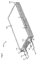
図2〜図4は、正の集電体210および負の集電体220を含む電気化学セル200を示す。半固体カソード240が、正の集電体210上に配置され、半固体アノード250が、負の集電体220上に配置されている。セパレータ230が、半固体カソード240と半固体アノード250との間に配置されている。電気化学セル200は、パウチ260の中に配置されている。
2-4 illustrate an
正の集電体210は、金属箔、例えば、銅箔もしくはアルミ箔、または、電気化学セル200に含まれる正の集電体210に関して記載されている任意の他の材料から形成することができる。正の集電体210は、約20μmから約40μmの範囲の厚さ、例えば、約25μm、約30μm、または約35μmであり、それらの間のすべての範囲を含む厚さを有することができる。いくつかの実施形態では、正の集電体210は、約20μm未満の厚さ、例えば、約5μm、6μm、7μm、8μm、9μm、10μm、12μm、14μm、16μm、または約18μmであり、それらの間のすべての範囲を含む厚さを有することができる。正の集電体210は、正のリード線214と結合されたタブ212を含む。いくつかの実施形態では、タブ212は、正のリード線214と結合するように所望の長さにカットすることができる。正のリード線は、例えば、超音波溶接、クランピング、クリンピング、接着テープなどの任意の適切な方法を用いて、タブ212に結合することが可能な、導電性金属(例えば銅またはアルミニウム)のストリップとすることができる。リング216が、正のリード線214の一部分に巻き付けられており、電気化学セル200がパウチ260に配置されたときにパウチ260の縁と位置合わせされる。したがって、パウチ260が密封されると、リング216は、パウチ260が確実に熱シールされるようにする。リング216は、絶縁性材料、例えば、サーリン(Surlyn)などの選定されたプラスチック、または任意の他の適切な材料から形成することができる。
The positive
負の集電体220は、金属箔、例えば、銅箔もしくはアルミ箔、または、電気化学セル200に含まれる負の集電体220に関して記載されている任意の他の材料から形成することができる。負の集電体220は、約20μmから約40μmの範囲の厚さ、例えば、約25μm、約30μm、または約35μmであり、それらの間のすべての範囲を含む厚さを有することができる。いくつかの実施形態では、負の集電体220は、約20μm未満の厚さ、例えば、約5μm、6μm、7μm、8μm、9μm、10μm、12μm、14μm、16μm、または約18μmであり、それらの間のすべての範囲を含む厚さを有することができる。負の集電体220は、負のリード線224と結合されたタブ222もまた含む。いくつかの実施形態では、タブ222は、負のリード線224と結合するように所望の長さにカットすることができる。負のリード線224は、正のリード線214と実質的に同様のものとすることができるので、さらなる詳細については本明細書では記載しない。リング226が、負のリード線224の一部分に巻き付けられており、電気化学セル200がパウチ260に配置されたときにパウチ260の縁と位置合わせされる。したがって、パウチ260が密封されると、リング226は、パウチ260が確実に熱シールされるようにする。リング226は、絶縁性材料、例えば、サーリンなどの選定されたプラスチック、または任意の他の適切な材料から形成することができる。
The negative
セパレータ230は、イオン透過膜とすることができ、電気化学セル200に含まれるセパレータ230に関して記載されているいずれの材料からも形成することが可能である。セパレータ230は、約10μmから約30μmの厚さ、例えば、約15μm、約20μm、または約25μmであり、それらの間のすべての範囲を含む厚さを有することができる。
半固体カソード240は、正の集電体210の、セパレータ230に近い方の第1の表面上に、例えば被覆されて、配置されている。セパレータ230から遠い方にある正の集電体210の第2の表面は、被覆がないままである。同様に、半固体アノード250は、負の集電体220の、セパレータ230に近い方の第1の表面上に、例えば被覆されて、配置されている。セパレータ230から遠い方にある負の集電体220の第2の表面は、被覆がないままである。別の言い方をすると、半固体カソード240および半固体アノード250は、正の集電体210および負の集電体220の片面だけにそれぞれ被覆されている。片面だけを被覆することにより、電気化学セル200を調製するのに要する時間を短縮する。これにより、半固体カソード240の配合物および/または半固体アノード250の配合物に含まれる電解質の蒸発および/または(例えば周囲湿度による)劣化を軽減することができる。半固体カソード240および半固体アノード250はそれぞれ、電気化学セル100に含まれる半固体カソード140および半固体アノード150に関して記載されているような、任意の構成要素(例えば活物質および/または導電材料、電解質、添加剤、ゲルポリマーなど)を用いて配合することができる。さらにまた、半固体カソード240および/または半固体アノード250はそれぞれ、少なくとも約250μmの厚さを有することができる。例えば、半固体カソード240および/または半固体アノード250は、約250μmから約2,000μmの範囲の厚さを有することができる。
The
調製された電気化学セル200は、電気化学セル200の材料を環境から気密的に隔離することが可能な、プリズム状のパウチ260に真空密封することができる。そのためパウチ260は、電解質溶媒および/または腐食性塩などといった有害物質が周囲環境に漏れ出すことを回避する働きをし、かつ、セルに水および/または酸素が浸透することを防止することができる。パウチ260のその他の機能は、例えば、内側層の圧縮パッケージング、安全性および操作性のための電圧分離、ならびに電気化学セル200の組立体の機械的保護を含むことができる。
The prepared
代表的なパウチ材料は、例えば、2枚または3枚の固体フィルム状の層に形成され、接着剤によって結合されるラミネート(例えば、多層シート)を含むことができる。本明細書で使用される場合、「ラミネート」という語は、互いに化学的に接着されていない材料の層のこともまた指す。例えば、層は、互いに面接触させ、例えば、ヒートシールのような、他の結合方法を用いて結合させることができる。いくつかの実施形態では、パウチ260は、ポリプロピレン、例えば、キャストプロピレンから形成することができる。いくつかの実施形態では、多層シートがセルの電気化学的機能要素として使用可能であるように、プラスチック材料で形成された第1の層すなわち内側層、および導電性材料で形成された第2の層を少なくとも含む多層ラミネートシートを含むケーシングまたはパウチを有する電気化学セルを形成することができる。例えば、いくつかの実施形態では、パウチの導電性材料(例えば、金属箔)は、セルの集電体として使用することができる。いくつかの実施形態では、金属箔はパススルータブとして使用することができる。したがって、セルパウチの多層またはラミネートシートは、パッケージング材料としての役割を果たすことに加えて、セルの電気化学的機能材料として使用することができる。多層ラミネートシートを含むケーシングまたはパウチを有する電気化学セルを製造するシステム、デバイス、および方法が、2014年11月17日出願の、「電気化学セルおよびその製造方法(Electrochemical Cells and Methods of Manufacturing the Same)」という名称の米国特許出願公開第2015/0171406号(「‘406号公開」とも呼ばれる)に記載されており、その開示内容全体が参照により本明細書に組み込まれている。
Exemplary pouch materials can include, for example, a laminate (eg, a multi-layer sheet) formed into two or three solid film layers and bonded together with an adhesive. As used herein, the term “laminate” also refers to layers of material that are not chemically bonded to each other. For example, the layers can be in surface contact with each other and bonded using other bonding methods, such as heat sealing. In some embodiments, the
複数の電気化学セル200、または本明細書に記載されている任意の他の電気化学セルを電気化学セルスタックに配置して、例えば、電気化学バッテリを形成することができる。次に図5〜図7を参照すると、電気化学セルスタック3000が示されており、そこには複数の電気化学セルが配置されている。電気化学セルスタック3000は、パウチ360の中に配置することができる。パウチ360は、例えば、図2〜図4に関して記載されているパウチ260と実質的に同様のものとすることが可能な真空密封パウチであり、したがって、さらなる詳細については本明細書では記載しない。
Multiple
電気化学セルスタック3000に含まれる複数の電気化学セルのそれぞれは、例えば、第2の電気化学セル300b(図6)は、電気化学セル100または200と実質的に同様のものとすることができる。複数の電気化学セルに含まれる集電体はそれぞれ、タブを含んでいる。例えば、図6に示されるように、第2の電気化学セル300bの正の集電体310b(図7)は、タブ312bを含み、第2の電気化学セル300bの負の集電体320bは、タブ322bを含んでいる。複数の電気化学セルに含まれる正の集電体のタブはそれぞれ、正のベイル(bail)313にまとめて結合され、これが次に正のリード線314に結合されている。いくつかの実施形態では、正の集電体のタブはそれぞれ、互いに曲げて重ね合わせられ、正のベイル313を形成することができる。いくつかの実施形態では、正のベイル313に含まれるタブは、正のリード線314と結合するように所望の長さにカットすることができる。いくつかの実施形態では、セルの内部に向かって配置されたセル300に含まれる正の集電体310および/または負の集電体320は、最も外側の電気化学セル300に含まれる正の集電体310のタブ312、および/または負の集電体320のタブ322よりも実質的に短いタブを有することができる。例えば、電気化学セル300cに含まれる正の集電体310cのタブは、電気化学セル300aに含まれる正の集電体310aのタブ、および電気化学セル300bに含まれる正の集電体310bのタブよりも実質的に長くすることができる。同様に、電気化学セル300aに含まれる負の集電体320aのタブは、電気化学セル300bに含まれる負の集電体320bのタブ、および電気化学セル300cに含まれる負の集電体320cのタブよりも実質的に長くすることができる。このような実施形態では、短い方のタブは、例えば、超音波溶接、クランピング、クリンピング、接着テープなどを介して、長い方のタブに結合させ、ベイル(すなわちベイル313および323)を形成することができる。次に、最も外側の正の集電体、および最も外側の負の集電体(例えば、正の集電体310cおよび負の集電体310a)の長い方のタブは、正のリード線314および負のリード線324に結合させることができる。このように、タブの形成に要する材料の量を減らすことにより、電気化学セル300のコストおよび/または総重量を減らすことができる。いくつかの実施形態では、最も内側の電気化学セル300の正の集電体310および負の集電体のタブは、電気化学セルスタック3000に含まれる残りの電気化学セルの、正の集電体310および負の集電体320のタブ310およびタブ320よりも長くすることができる。いくつかの実施形態では、長い方のタブを含んでいる正の集電体310および/または負の集電体320は、電気化学セルスタック3000に含まれるその他の電気化学セル300に含まれる正の集電体310および/または負の集電体320よりも実質的に厚くすることができる。いくつかの実施形態では、正の集電体310および負の集電体320はそれぞれ、パウチ360の外に延在するように十分な長さ(例えば、最も外側の正の集電体310の正のタブ312および最も外側の負の集電体320の負のタブ322とほぼ同じ長さ)とすることが可能なタブを有することができる。このような実施形態では、例えば、正の集電体310のそれぞれのタブは、例えば、超音波溶接、クランピング、クリンピング、接着テープなどを介して、まとめて結合され、正のベイル(例えばベイル313)を形成することができる。同様に、負の集電体320のそれぞれのタブは、本明細書に記載されているようにまとめて結合され、負のベイル(例えばベイル323)を形成することができる。本明細書に記載されているように、正のベイル(正の集電体のそれぞれのタブを含む)および負のベイル(負の集電体のそれぞれのタブを含む)は、パウチの外に延在することが可能であり、電気化学セルスタック3000を電気的にインタフェースするのに用いることができる。別の言い方をすると、このような実施形態では、電気化学セルスタック3000は、正のベイルおよび負のベイルを直接介して外部の電子部品に電気的に結合させて、正のリード線314および負のリード線324が、電気化学セルスタックに含まれないようにすることが可能である。
Each of the plurality of electrochemical cells included in the
正のリード線314は、例えば、超音波溶接、クランピング、クリンピング、接着テープなどの任意の適切な方法を用いて、正のベイル313に結合することが可能な、導電性金属(例えば銅またはアルミニウム)のストリップとすることができる。リング316が、正のリード線314の一部分に巻き付けられており、電気化学セル300がパウチ360に配置されたときにパウチ360の縁と位置合わせされる。したがって、パウチ360が密封されると、リング316は、パウチ360が確実に熱シールされるようにする。リング316は、絶縁性材料、例えば、サーリンなどの選定されたプラスチック、または任意の他の適切な材料から形成することができる。同様に、複数の電気化学セルに含まれる負の集電体のタブはそれぞれ、負のベイル323にまとめて結合され、これが次に負のリード線324に結合されている。いくつかの実施形態では、負の集電体のタブはそれぞれ、互いに曲げて重ね合わせられ、負のベイル323を形成することができる。いくつかの実施形態では、負のベイル323に含まれるタブは、正のリード線314と結合するように所望の長さにカットすることができる。負のリード線324は、正のリード線314と実質的に同様のものとすることができる。したがって、さらなる詳細については本明細書では記載しない。さらに、リング326が、負のリード線324の一部分に巻き付けられており、電気化学セル300がパウチ360に配置されたときにパウチ360の縁と位置合わせされる。リング326は、リング316と実質的に同様のものとすることができる。したがって、さらなる詳細については本明細書では記載しない。
The
図7は、線AA(図6)に沿った、電気化学セルスタック3000の一部分の側面断面図を示す。電気化学セルスタック3000の一部分は、第1の電気化学セル300aと、第2の電気化学セル300bと、第3の電気化学セルを300cと、を含む。第1の電気化学セル300aは、第1の正の集電体310aと、第1の負の集電体320aと、第1のセパレータ330aと、を含む。第1の半固体カソード340aが、第1の正の集電体310aの、第1のセパレータ330aに面した片面だけに配置されている。同様に、第1の半固体アノード350aが、第1の負の集電体320aの、第1のセパレータ330aに面した片面だけに配置されている。第1のセパレータ330aは、第1の半固体カソード340aと、第1の半固体アノード350aとの間に配置されている。
FIG. 7 shows a side cross-sectional view of a portion of
第2の電気化学セル300bは、第2の正の集電体310bと、第2の負の集電体320bと、第2のセパレータ330bと、を含む。第2の半固体カソード340bが、第2の正の集電体310bの、第2のセパレータ330bに面した片面だけに配置されている。同様に、第2の半固体アノード350bが、第2の負の集電体320bの、第2のセパレータ330bに面した片面だけに配置されている。第2のセパレータ330bは、第2の半固体カソード340bと、第2の半固体アノード350bとの間に配置されている。
The second
第3の電気化学セル300cは、第3の正の集電体310cと、第3の負の集電体320cと、第3のセパレータ330cと、を含む。第3の半固体カソード340cが、第3の正の集電体310cの、第3のセパレータ330cに面した片面だけに配置されている。同様に、第3の半固体アノード350cが、第3の負の集電体320cの、第3のセパレータ330cに面した片面だけに配置されている。第3のセパレータ330cは、第3の半固体カソード340cと、第3の半固体アノード350cとの間に配置されている。
The third
第1の電気化学セル300a、第2の電気化学セル300b、および第3の電気化学セル300cは、互いに実質的に同様のものとすることができる。電気化学セルスタック3000に含まれる電気化学セルのそれぞれに含まれる正の集電体、負の集電体、およびセパレータは、電気化学セル100に含まれる正の集電体110、負の集電体120、およびセパレータ130に関して記載されている任意の材料から形成することができる。さらに、電気化学セルスタック3000の電気化学セルのそれぞれに含まれる半固体カソードおよび半固体アノードは、電気化学セル100に含まれる半固体カソード140および半固体アノード150に関して記載されている任意の材料または方法を用いて配合することができる。
The first
第2の電気化学セル300bは、第2の正の集電体310bの被覆がない方の面が第1の正の集電体310aの被覆がない方の面に隣接し、かつ、当接するように、第1の電気化学の300aに配置されている。同様に、第3の電気化学セル300cは、第3の負の集電体320cの被覆がない方の面が第1の負の集電体320aの被覆がない方の面に隣接し、かつ、当接するように、第1の電気化学セル300aに配置されている。電気化学セルスタック3000は8つの電気化学セルを含んでいるものとして示されている(図6)が、任意の数の電気化学セルを電気化学セルスタック3000に含めることができる。本明細書には示されていないが、いくつかの実施形態では、スペーサ、例えば、電気絶縁性および/または断熱性のスペーサを、それぞれの隣接した電気化学セル間に配置することができる。いくつかの実施形態では、スペーサは、電気化学セルスタック3000に含まれる電気化学セルのそれぞれに積み重ね圧力をかけるように構成することができる。適切なスペーサは、例えば、発泡体パッド、ゴムパッド、プラスチックシート、紙または段ボールのストリップなどを含むことができる。
In the second
従来の電気化学セルスタックと比較して、電気化学セルスタック3000は、より短期間で形成することができる。これにより、本明細書に記載されているように電解質の蒸発および/または劣化を最小限にすることができる。電気化学セルスタック3000は、本明細書に記載されている半固体電極が集電体の両面に被覆されている同様のサイズの電気化学セルスタックと比較すると、不活性物質に対する活物質の比率が低くなる場合がある。しかしながら、従来の電極が集電体の両面に被覆されている従来の電気化学セルスタックと比較すると、電気化学セルスタックは、不活性物質に対する活物質の高い比率を、依然として有することができる。その理由は、半固体電極は、約200μmよりも厚くすることが概して不可能な従来の電極と比較して、はるかに厚く、例えば約250μmから約2,000μmの範囲の厚さにすることができるからである。したがって、電気化学セルスタック3000は、同等のエネルギー密度および電荷容量を生み出す従来の電気化学セルスタックと比較して、電気化学セルスタック3000に含まれる電気化学セル(例えば電気化学セル300)の数が少なくても、所望のエネルギー密度および電荷容量を生み出すことができる。さらに、電気化学セルスタック300に含まれる、片面だけが被覆された電気化学セル300は、従来のセルが含み得ない安全性特徴または保護特徴を含むことができる。例えば、電気化学セルスタック3000に含まれる集電体(すなわち正の集電体310および負の集電体320)の縁のまわりに安全な周囲または壁を配置して、半固体カソード230および半固体アノード240を保護することができる。さらにまた、電気化学セルスタック3000に含まれる隣接した電気化学セル間の軽微な位置合わせ不良が許容可能であることで、従来の電気化学セルスタックと比較して、より短時間で電気化学セルスタック3000が形成可能であるようになっている。
Compared to a conventional electrochemical cell stack, the
いくつかの実施形態では、電気化学セルスタックは、複数の正の集電体および負の集電体を含む複数のセルスタックを含むことができる。複数の正の集電体のうちの1つ、および複数の負の集電体のうちの1つは、残りの集電体のタブよりも実質的に長いタブであって、外部の電子機器類とインタフェースするように電気化学セルのパウチの外に延在することが可能なタブを有することが可能であることで、リード線が必要なくなっている。例えば、図8を参照すると、電気化学セルスタック4000が示されており、そこには複数の電気化学セルが配置されている。電気化学セルスタック4000は、パウチ(図示せず)、例えば、図2〜図4に関して記載されているパウチ260と実質的に同様のものとすることが可能な真空密封パウチの中に配置することができる。
In some embodiments, the electrochemical cell stack can include a plurality of cell stacks including a plurality of positive current collectors and a negative current collector. One of the plurality of positive current collectors and one of the plurality of negative current collectors are substantially longer than the tabs of the remaining current collectors, the external electronic device The ability to have tabs that can extend out of the pouch of the electrochemical cell to interface with the device eliminates the need for leads. For example, referring to FIG. 8, an
電気化学セルスタック4000に含まれる複数の電気化学セルはそれぞれ、電気化学セル100、200、または300と実質的に同様のものとすることが可能であり、したがって、さらなる詳細については本明細書では記載しない。複数の電気化学セルに含まれる集電体はそれぞれ、タブを含んでいる。例えば、図8に示されるように、最も外側の正の集電体410bは、残りの正の集電体のタブよりも実質的に長いタブ412bを含むことができる。正の集電体のタブは、ベイル413にまとめて結合され、例えば、超音波溶接、クランピング、クリンピング、接着テープなどといったような結合機構413を用いて互いに結合することができる。同様に、最も外側の負の集電体420aは、残りの負の集電体のタブよりも実質的に長いタブ422aを含むことができる。負の集電体のタブは、ベイル423にまとめて結合され、例えば、超音波溶接、クランピング、クリンピング、接着テープなどといったような結合機構425を用いて互いに結合することができる。このように、正の集電体および負の集電体のタブはそれぞれ、互いに電子的に結合されることで、それぞれ残りのタブよりも実質的に長い正の集電体410bのタブ412bおよび負の集電体420bのタブ422aが、ベイルの外およびパウチの外に延在するようになっている。したがって、正のタブ412bおよび負のタブ422aは、外部の電子機器類との電子インタフェースに使用可能であることで、余分な構成要素(例えばリード線)をまったく使用しないようになっている。
Each of the plurality of electrochemical cells included in the
さらに拡大して、図9は、図8において矢印Bによって示された電気化学セルスタック4000の一部分の側面図を示す。それは、負の集電体のベイルを含む。電気化学セルスタックは、8つのセルスタックを含み、そのそれぞれが正の集電体および負の集電体を含む。図9に示されるように、電気化学セルスタック4000は、8つの負の集電体422a〜422hを含む。集電体は、本明細書に記載されているように、ベイル423にまとめて接合され、結合機構425を用いて互いに結合されている。負の集電体420a(図8)の負のタブ422aは、残りの負の集電体の負のタブ422b〜422hよりも実質的に長い。したがって、タブ422aは、ベイルを越えて、電気化学セルスタック4000をパッケージングするのに用いられるパウチの外に延在することができる。このように、タブ422aは、電気化学セルスタック4000と外部の電子機器類とのインタフェースに用いることができることにより、電気化学セルスタック4000に含まれる負の集電体のそれぞれが、タブ422aを介して外部の電子機器類と電子的につながった状態になっている。これにより、外部の結合部品、例えば、負のリード線は使用されず、製造がより簡易になり、コストが低減される。
Further enlarged, FIG. 9 shows a side view of a portion of the
図10は、複数の電気化学セルを含む電気化学セルスタックを調製するための例示的な方法400を示すフロー図を図示する。方法400は、正の集電体402の片面に半固体カソードを被覆するステップを含む。半固体カソードは、例えば、半固体カソード140、240、または本明細書に記載されている任意の他の半固体カソードを含むことができる。適切な正の集電体は、例えば、正の集電体110、210、または本明細書に記載されている任意の他の正の集電体を含むことができる。次に、半固体アノードが、負の集電体404の片面だけに被覆される。半固体アノードは、本明細書に記載されている半固体アノードのいずれか、例えば、半固体アノード150、250、または本明細書に記載されている任意の他の半固体アノードを含むことができる。適切な負の集電体は、例えば、負の集電体の120、220、または本明細書に記載されている任意の他の負の集電体を含むことができる。セパレータ(例えば、セパレータ130、230、または本明細書に記載されている任意の他のセパレータ)を、半固体カソードと半固体アノードとの間に配置して、第1の電気化学セル406を形成する。第2の電気化学セルを、第1の電気化学セル408と実質的に同じやり方で形成する。さらに、第3の電気化学セルを、第1の電気化学セル410と実質的に同じやり方で形成する。第1の電気化学セル、第2の電気化学セル、および第3の電気化学セルはそれぞれ、電気化学セル100、200、または本明細書に記載されている任意の他の電気化学セルと実質的に同様のものとすることが可能である。
FIG. 10 illustrates a flow diagram illustrating an
電気化学セルスタックを形成するために、第2の電気化学セルは、第2の電気化学セルの正の集電体の、被覆がない方の面が、第1の電気化学セル412の正の集電体の、被覆がない方の面の上に(例えば隣接して、または当接して)配置されるように、第1の電気化学セルの上に配置される。次に、第3の電気化学セルは、第3の電気化学セルの負の集電体の被覆がない方の面が、第1の電気化学セルの負の集電体の被覆がない方の面に配置されるように、第1の電気化学セルの上に(例えば隣接して、または当接して)配置されて、電気化学セルスタックを形成している。電気化学セルスタックは、電気化学セルスタック3000、または本明細書に記載されている任意の他の電気化学セルスタックと実質的に同様のものとすることが可能である。いくつかの実施形態では、電気化学セルスタックの形成に要する時間は、第1の電気化学セル、第2の電気化学セル、および第3の電気化学セルのうちのいずれかの、半固体アノードまたは半固体カソードに含まれる電解質の蒸発が大幅に低減されるように、十分に短くなり得る。
In order to form an electrochemical cell stack, the second electrochemical cell has a positive current collector of the second electrochemical cell, the surface of the first
いくつかの実施形態では、方法400は、第1の電気化学セルの正の集電体と、第2の電気化学セルの正の集電体との間に第1のスペーサを配置するステップ、および/または第3の電気化学セルの負の集電体と、第1の電気化学セルの負の集電体との間に第2のスペーサを配置するステップを任意選択で含むことができる。スペーサは、例えば、発泡体パッド、ゴムパッド、プラスチックシート、紙または段ボールのストリップなどといったような、断熱性および/または電気絶縁性材料を含むことができる。
In some embodiments, the
図11A〜図11Iは、一実施形態に従って、集電体の片面だけに被覆される半固体電極を有する電気化学セル500を製造するプロセスにおける様々なステップを図示する。図11Aに示されるように、フレーム562(「スペーサフレーム」とも呼ばれる)が、集電体510の上に配置されている。それは電源接続タブ512を含んでいる。集電体510は、(本明細書では「集電体ホルダー」とも呼ばれる)ホルダー565の上に置くことができる。例えば、ホルダー565は、集電体510を所定位置に保持するように、任意選択で複数の小孔(図示せず)を介してホルダー565の表面全体にわたって真空処理を施すことができる。フレーム562は、集電体510の上に置いたときに、下にある集電体510を露出することが可能な開口部575を有する。
11A-11I illustrate various steps in a process of manufacturing an
図11Bは、フレーム562の開口部575によって画定された、集電体510の露出した部分の上に配置されている電極スラリー540を図示する。開口部575は、完成した電極540の表面積を画定し、フレーム562の厚さは、完成した電極540の厚さを画定している。図11Cおよび図11Dは、集電体510の露出した部分の表面に沿って平坦化、または塗布された電極スラリー540を示す。いくつかの実施形態では、ブレード580(本明細書では「ドクターブレード(doctor blade)」とも呼ばれる)、または直線状の機器を用いて電極スラリー540を塗布することができる。いくつかの実施形態では、ブレード580および/またはホルダー565を振動発生源(図示せず)に動作可能に結合させ、電極スラリー540の堆積時または平坦化時に、ブレード580またはホルダー565が振動するようにしてもよい。振動により、スラリー堆積ステップの間、またはスラリー堆積ステップの後に、半固体電極材料540を分散し易くすることができる。
FIG. 11B illustrates
任意選択で、例えば、光学分析ツールまたは任意の分析ツールなどの機器(図示せず)が、光干渉法もしくはレーザ干渉法、楕円偏光解析法、または光走査プローブもしくはレーザ走査プローブを含む非接触測定法のいずれかを用いて、塗布された電極スラリー540の表面モフォロジを検査し、および任意選択で、表面の均一性(例えば厚さ)を測定する。非接触機器は、ブレード580が電極スラリー540を塗布するときに、その場で配備することができる。
Optionally, for example, an instrument such as an optical analysis tool or any analysis tool (not shown) includes optical interferometry or laser interferometry, elliptical ellipsometry, or non-contact measurement including an optical scanning probe or laser scanning probe. Using any of the methods, the surface morphology of the applied
電極スラリー540が塗布された後、図11Eに示されるように、フレーム562は、集電体510の露出した部分の上に塗布された電極540の部分だけを残して除去することができる。図11Fに図示されるように、セパレータ530を電極540の上に置いて、セパレータ530が電極540を覆うようにすることができる。
After the
上記の図11A〜図11Fに図示された製造ステップは、集電体の上に電極を堆積するステップに該当する。例として、電極540は、カソードとすることが可能であり、集電体510は、正の集電体とすることが可能である。図11A〜図11Eに図示された製造ステップを繰り返して、負の集電体520の上に半固体アノード550を配置することができる。しかしながら、電気化学セル500ではセパレータ530を1つしか用いないので、図11Fに示された製造ステップは、半固体カソード堆積ステップまたは半固体アノード堆積ステップのうちの1つに関してのみ実行される。
The manufacturing steps illustrated in FIGS. 11A to 11F correspond to the steps of depositing electrodes on the current collector. As an example,
図11Gに示されるように、半固体カソード540および半固体アノード550がいずれもそれぞれの集電体510および520の上に配置されれば、半固体カソード540および半固体アノード550が、図示されるように向かい合って互いに重ね合わされるように、ただし、セパレータ530によって分離されるように、それらを位置合わせすることができる。示されているように、半固体アノード550は、負の集電体520の下側にあるので、見えない。組み立て後の電極スタックは、図3に示された図に類似している。
As shown in FIG. 11G, if the
図11Hに最も良く示されているように、電気化学セル500は、パウチ560の内部に配置された、ただ1つのカソード−セパレータ−アノードからなるスタックを含み、次にそれが真空処理566およびヒートシール567されて、図11Iに示されているような、完成した電気化学セル500を形成する。正の集電体510は、電源接続タブ512を含んでおり、一方負の集電体520は、電源接続タブ522を含んでいる。パウチ560の中の完成した電気化学セル500は、図2に示された電気化学セル200と実質的に類似したものとすることができる。いくつかの実施形態では、複数の電気化学セル500を積層させて電気化学セルスタックを形成することができる。それは、図5〜図7に図示された電気化学セルスタック3000と実質的に類似したものとすることができる。
As best shown in FIG. 11H, the
以上、システム、方法、およびデバイスの様々な実施形態について説明してきたが、それらが限定ではなく単なる例として提示されたものであることを理解されたい。上記の方法およびステップが特定の順序で発生する特定の事象を示している場合、本開示の恩恵を受ける当業者であれば、特定のステップの順序付けを修正することができ、このような修正が本発明の変形例によるものであることを認識するであろう。加えて、可能であれば、特定のステップを並行プロセスにおいて同時に実行してもよく、また、上述のように順序に従って実行してもよい。実施形態を具体的に図示および説明してきたが、形式および細部における様々な変更を行い得ることが理解されよう。 Although various embodiments of systems, methods and devices have been described above, it should be understood that they have been presented by way of example only and not limitation. Where the above methods and steps are indicative of particular events occurring in a particular order, one of ordinary skill in the art having the benefit of this disclosure can modify the ordering of particular steps, and such modifications It will be appreciated that this is a variation of the present invention. In addition, if possible, certain steps may be performed simultaneously in a parallel process and may be performed in order as described above. While embodiments have been specifically shown and described, it will be understood that various changes in form and detail may be made.
例えば、特定の特徴および/または構成要素の組み合わせを有するものとして様々な実施形態を説明してきたが、本明細書に記載されているいずれかの実施形態から、任意の特徴および/または構成要素の任意の組み合わせまたは部分的組み合わせを有する他の実施形態が可能である。例えば、電気化学セルのいくつかの実施形態はプリズム状であるとして記載されていたが、他の実施形態では、電気化学セルは、曲線状、湾曲した形状、波状とすることができ、あるいは任意の他の形状を有することができる。加えて、様々な構成要素の特定の構成を変更することもまた可能である。例えば、様々な構成要素のサイズおよび特定の形状は、本明細書に記載されているような機能を依然として提供しつつも、示された実施形態とは異なるものとすることができる。 For example, although various embodiments have been described as having particular features and / or combinations of components, any feature and / or component of any of the embodiments described herein can be used. Other embodiments having any combination or partial combination are possible. For example, while some embodiments of the electrochemical cell have been described as being prismatic, in other embodiments the electrochemical cell can be curved, curved, wavy, or any It can have other shapes. In addition, it is also possible to change the specific configuration of the various components. For example, the size and specific shape of the various components may differ from the illustrated embodiments while still providing functionality as described herein.
Claims (23)
前記正の集電体の前記第1の表面上だけに配置された半固体カソードと、
第1の表面および第2の表面を有する負の集電体と、
前記負の集電体の前記第1の表面上だけに配置された半固体アノードと、
前記正の集電体の前記第1の表面と前記負の集電体の前記第1の表面との間に配置されたセパレータと、
を含む電気化学セル。 A positive current collector having a first surface and a second surface;
A semi-solid cathode disposed only on the first surface of the positive current collector;
A negative current collector having a first surface and a second surface;
A semi-solid anode disposed only on the first surface of the negative current collector;
A separator disposed between the first surface of the positive current collector and the first surface of the negative current collector;
Including electrochemical cell.
第1の表面および第2の表面を有する集電体を含む第2の電気化学セルであって、前記集電体の前記第1の表面の上に半固体電極が配置されている第2の電気化学セルと、
を含むとともに、
前記第2の電気化学セルの前記集電体の前記第2の表面が、前記第1の電気化学セルの前記集電体の前記第2の表面に結合されている電気化学セルスタック。 A first electrochemical cell comprising a current collector having a first surface and a second surface, wherein a semi-solid electrode is disposed on the first surface of the current collector. An electrochemical cell;
A second electrochemical cell including a current collector having a first surface and a second surface, wherein a second electrode is disposed on the first surface of the current collector. An electrochemical cell;
Including
An electrochemical cell stack in which the second surface of the current collector of the second electrochemical cell is bonded to the second surface of the current collector of the first electrochemical cell.
正の集電体の第1の表面の上に半固体カソードを被覆するステップと、
負の集電体の第1の表面の上に半固体アノードを被覆するステップと、
前記半固体カソードと前記半固体アノードとの間にセパレータを配置するステップと、
前記正の集電体、前記負の集電体、および前記セパレータをパウチの中に配置するステップと、
前記パウチを密封して前記電気化学セルを形成するステップと、
を含む方法。 A method for producing an electrochemical cell, comprising:
Coating a semi-solid cathode on the first surface of the positive current collector;
Coating a semi-solid anode on the first surface of the negative current collector;
Placing a separator between the semi-solid cathode and the semi-solid anode;
Disposing the positive current collector, the negative current collector, and the separator in a pouch;
Sealing the pouch to form the electrochemical cell;
Including methods.
前記正の集電体の前記第1の表面上に、開口部を画定するフレームを配置するステップと、
前記フレームの前記開口部の中へ前記半固体カソードを配置するステップと、
前記開口部から余分な半固体カソード材料を除去するステップと、
をさらに含む請求項11に記載の方法。 Coating the semi-solid cathode on the first surface of the positive current collector;
Placing a frame defining an opening on the first surface of the positive current collector;
Placing the semi-solid cathode into the opening of the frame;
Removing excess semi-solid cathode material from the opening;
The method of claim 11, further comprising:
前記負の集電体の前記第1の表面上に、開口部を画定するフレームを配置するステップと、
前記フレームの前記開口部の中へ前記半固体アノードを配置するステップと、
前記開口部から余分な半固体アノード材料を除去するステップと、
をさらに含む請求項11に記載の方法。 Coating the semi-solid anode on the first surface of the negative current collector;
Placing a frame defining an opening on the first surface of the negative current collector;
Disposing the semi-solid anode into the opening of the frame;
Removing excess semi-solid anode material from the opening;
The method of claim 11, further comprising:
第1の集電体の第1の表面の上に第1の半固体電極材料を配置するステップと、
第2の集電体の第1の表面の上に第2の半固体電極材料を配置するステップと、
前記第2の集電体の前記第2の表面上に前記第1の集電体の前記第2の表面を配置してバイポーラ電極を形成するステップと、
を含む方法。 A method for producing an electrochemical cell, comprising:
Disposing a first semi-solid electrode material on a first surface of a first current collector;
Disposing a second semi-solid electrode material on the first surface of the second current collector;
Disposing the second surface of the first current collector on the second surface of the second current collector to form a bipolar electrode;
Including methods.
Priority Applications (1)
| Application Number | Priority Date | Filing Date | Title |
|---|---|---|---|
| JP2021092052A JP2021144947A (en) | 2014-11-05 | 2021-06-01 | Electrochemical cell having semi-solid electrode and method of manufacturing the same |
Applications Claiming Priority (3)
| Application Number | Priority Date | Filing Date | Title |
|---|---|---|---|
| US201462075373P | 2014-11-05 | 2014-11-05 | |
| US62/075,373 | 2014-11-05 | ||
| PCT/US2015/058992 WO2016073575A1 (en) | 2014-11-05 | 2015-11-04 | Electrochemical cells having semi-solid electrodes and methods of manufacturing the same |
Related Child Applications (1)
| Application Number | Title | Priority Date | Filing Date |
|---|---|---|---|
| JP2021092052A Division JP2021144947A (en) | 2014-11-05 | 2021-06-01 | Electrochemical cell having semi-solid electrode and method of manufacturing the same |
Publications (1)
| Publication Number | Publication Date |
|---|---|
| JP2017533548A true JP2017533548A (en) | 2017-11-09 |
Family
ID=54540262
Family Applications (3)
| Application Number | Title | Priority Date | Filing Date |
|---|---|---|---|
| JP2017517309A Pending JP2017533548A (en) | 2014-11-05 | 2015-11-04 | Electrochemical cell having semi-solid electrode and method for producing the same |
| JP2021092052A Pending JP2021144947A (en) | 2014-11-05 | 2021-06-01 | Electrochemical cell having semi-solid electrode and method of manufacturing the same |
| JP2023093725A Pending JP2023105136A (en) | 2014-11-05 | 2023-06-07 | Electrochemical cell with semi-solid electrodes and method of making same |
Family Applications After (2)
| Application Number | Title | Priority Date | Filing Date |
|---|---|---|---|
| JP2021092052A Pending JP2021144947A (en) | 2014-11-05 | 2021-06-01 | Electrochemical cell having semi-solid electrode and method of manufacturing the same |
| JP2023093725A Pending JP2023105136A (en) | 2014-11-05 | 2023-06-07 | Electrochemical cell with semi-solid electrodes and method of making same |
Country Status (9)
| Country | Link |
|---|---|
| US (4) | US10637038B2 (en) |
| EP (3) | EP3216067B1 (en) |
| JP (3) | JP2017533548A (en) |
| KR (3) | KR102793671B1 (en) |
| CN (2) | CN112803057A (en) |
| CA (1) | CA2962788C (en) |
| MY (1) | MY180711A (en) |
| PH (1) | PH12017500654A1 (en) |
| WO (1) | WO2016073575A1 (en) |
Cited By (12)
| Publication number | Priority date | Publication date | Assignee | Title |
|---|---|---|---|---|
| JP2019521499A (en) * | 2016-07-22 | 2019-07-25 | ハイドロ−ケベック | Flexible electrode-separator elements and processes for their preparation |
| JP2021530829A (en) * | 2018-07-09 | 2021-11-11 | 24エム・テクノロジーズ・インコーポレイテッド24M Technologies, Inc. | Continuous and semi-continuous methods of semi-solid electrode and battery manufacturing |
| JP7053971B1 (en) | 2019-03-21 | 2022-04-12 | ホーフェイ ゴション ハイテク パワー エナジー カンパニー リミテッド | Multilayer composite with anisotropic thermal conductivity for safe pack design |
| EP3968423A4 (en) * | 2019-07-08 | 2022-11-23 | LG Energy Solution, Ltd. | SECONDARY BATTERY AND ITS MANUFACTURING METHOD |
| WO2024024785A1 (en) | 2022-07-28 | 2024-02-01 | 富士フイルム株式会社 | Production method for sheet-like electrode molding |
| WO2024024786A1 (en) | 2022-07-28 | 2024-02-01 | 富士フイルム株式会社 | Electrode material manufacturing method, battery electrode manufacturing method, and battery manufacturing method |
| US11949094B2 (en) | 2021-04-01 | 2024-04-02 | Prime Planet Energy & Solutions, Inc. | Method for manufacturing electrode for secondary battery, and moisture powder |
| WO2024075575A1 (en) | 2022-10-03 | 2024-04-11 | 富士フイルム株式会社 | Method for manufacturing electrode layer |
| WO2024214579A1 (en) | 2023-04-13 | 2024-10-17 | 富士フイルム株式会社 | Method for manufacturing electrode layer and apparatus for manufacturing electrode layer |
| WO2024214580A1 (en) | 2023-04-13 | 2024-10-17 | 富士フイルム株式会社 | Method of producing electrode layer |
| US12125984B2 (en) | 2020-10-09 | 2024-10-22 | 24M Technologies, Inc. | Methods of continuous and semi-continuous production of electrochemical cells |
| US12368156B2 (en) | 2021-04-01 | 2025-07-22 | Prime Planet Energy & Solutions, Inc. | Moisture powder and method for manufacturing non-aqueous electrolyte secondary battery including electrode composed of said moisture powder |
Families Citing this family (53)
| Publication number | Priority date | Publication date | Assignee | Title |
|---|---|---|---|---|
| US11909077B2 (en) | 2008-06-12 | 2024-02-20 | Massachusetts Institute Of Technology | High energy density redox flow device |
| US8722226B2 (en) | 2008-06-12 | 2014-05-13 | 24M Technologies, Inc. | High energy density redox flow device |
| EP2754194B1 (en) | 2011-09-07 | 2018-12-12 | 24M Technologies, Inc. | Semi-solid electrode cell having a porous current collector and methods of manufacture |
| US9401501B2 (en) | 2012-05-18 | 2016-07-26 | 24M Technologies, Inc. | Electrochemical cells and methods of manufacturing the same |
| US9484569B2 (en) | 2012-06-13 | 2016-11-01 | 24M Technologies, Inc. | Electrochemical slurry compositions and methods for preparing the same |
| US9362583B2 (en) | 2012-12-13 | 2016-06-07 | 24M Technologies, Inc. | Semi-solid electrodes having high rate capability |
| EP4195322A1 (en) | 2013-03-15 | 2023-06-14 | 24M Technologies, Inc. | Asymmetric battery having a semi-solid cathode and high energy density anode |
| WO2015009990A2 (en) | 2013-07-19 | 2015-01-22 | 24M Technologies, Inc. | Semi-solid electrodes with polymer additive |
| US10230128B2 (en) | 2014-04-09 | 2019-03-12 | 24M Technologies, Inc. | Damage tolerant batteries |
| JP2016076475A (en) * | 2014-08-06 | 2016-05-12 | 株式会社半導体エネルギー研究所 | Electronic device and eyeglass-type device having secondary battery |
| KR102708552B1 (en) * | 2014-09-19 | 2024-09-24 | 가부시키가이샤 한도오따이 에네루기 켄큐쇼 | Secondary battery |
| EP3207579B1 (en) | 2014-10-13 | 2020-01-29 | 24M Technologies, Inc. | Systems and methods for series battery charging and forming |
| WO2016073438A1 (en) | 2014-11-03 | 2016-05-12 | 24M Technologies, Inc. | Pre-lithiation of electrode materials in a semi-solid electrode |
| CA2962788C (en) | 2014-11-05 | 2024-04-09 | 24M Technologies, Inc. | Electrochemical cells having semi-solid electrodes and methods of manufacturing the same |
| US10115970B2 (en) | 2015-04-14 | 2018-10-30 | 24M Technologies, Inc. | Semi-solid electrodes with porous current collectors and methods of manufacture |
| US10593952B2 (en) | 2015-05-19 | 2020-03-17 | 24M Technologies Inc. | Mechanical systems and methods for providing edge support and protection in semi-solid electrodes |
| MY184234A (en) | 2015-06-18 | 2021-03-29 | Takaaki Fukushima | Single pouch battery cells and methods of manufacture |
| US10411310B2 (en) | 2015-06-19 | 2019-09-10 | 24M Technologies, Inc. | Methods for electrochemical cell remediation |
| US11005087B2 (en) | 2016-01-15 | 2021-05-11 | 24M Technologies, Inc. | Systems and methods for infusion mixing a slurry based electrode |
| CN205376656U (en) * | 2016-01-20 | 2016-07-06 | 宁德新能源科技有限公司 | Secondary battery |
| CN110612620A (en) | 2017-02-01 | 2019-12-24 | 24M技术公司 | System and method for improving safety features in electrochemical cells |
| WO2018183828A1 (en) | 2017-03-31 | 2018-10-04 | 24M Technologies, Inc. | Overcharge protection of batteries using current interrupt devices |
| WO2019027901A1 (en) | 2017-07-31 | 2019-02-07 | 24M Technologies, Inc. | Current interrupt devices using shape memory materials |
| US10854869B2 (en) | 2017-08-17 | 2020-12-01 | 24M Technologies, Inc. | Short-circuit protection of battery cells using fuses |
| JP7029921B2 (en) * | 2017-10-10 | 2022-03-04 | 日産自動車株式会社 | Electrodes for non-aqueous electrolyte secondary batteries |
| DE102017218158A1 (en) | 2017-10-11 | 2019-04-11 | Robert Bosch Gmbh | Method for producing an electrode and galvanic element comprising an electrode |
| US12519176B2 (en) | 2017-10-30 | 2026-01-06 | Kyocera Corporation | Electrochemical cell and electrochemical cell stack |
| CN111712942A (en) * | 2018-01-08 | 2020-09-25 | 24M技术公司 | Electrochemical cell including permselective membrane, system and method of making the same |
| JP7535948B2 (en) | 2018-05-24 | 2024-08-19 | 24エム・テクノロジーズ・インコーポレイテッド | High energy density compositional gradient electrode and method of manufacture thereof |
| US11094487B2 (en) | 2018-06-25 | 2021-08-17 | 24M Technologies, Inc. | Current interrupt device based on thermal activation of frangible glass bulb |
| WO2020160322A1 (en) | 2019-01-30 | 2020-08-06 | Horizon Pharma Rheumatology Llc | Tolerization reduces intolerance to pegloticase and prolongs the urate lowering effect (triple) |
| US11631920B2 (en) | 2019-06-27 | 2023-04-18 | 24M Technologies, Inc. | Dual electrolyte electrochemical cells, systems, and methods of manufacturing the same |
| EP4052319A1 (en) | 2019-11-01 | 2022-09-07 | 24M Technologies, Inc. | Electrochemical cells with separator seals, and methods of manufacturing the same |
| KR20210056779A (en) * | 2019-11-11 | 2021-05-20 | 삼성에스디아이 주식회사 | All Solid secondary battery |
| CN114730951A (en) * | 2019-11-20 | 2022-07-08 | 24M技术公司 | Electrochemical cells connected in series in a single pouch and method of making same |
| US11462722B2 (en) | 2020-01-21 | 2022-10-04 | 24M Technologies, Inc. | Apparatuses and processes for forming a semi-solid electrode having high active solids loading and electrochemical cells including the same |
| US11742525B2 (en) | 2020-02-07 | 2023-08-29 | 24M Technologies, Inc. | Divided energy electrochemical cell systems and methods of producing the same |
| US11749804B2 (en) | 2020-02-21 | 2023-09-05 | 24M Technologies, Inc. | Electrochemical cells with electrode material coupled directly to film and methods of making the same |
| CN115917775A (en) | 2020-06-04 | 2023-04-04 | 24M技术公司 | Electrochemical cell having one or more segmented current collectors and method of making same |
| US12381277B2 (en) | 2020-06-17 | 2025-08-05 | 24M Technologies, Inc. | Electrochemical cells with flame retardant mechanism and methods of producing the same |
| KR20230027231A (en) * | 2020-06-24 | 2023-02-27 | 24엠 테크놀로지즈, 인크. | Electrochemical Cells and Electrodes with Carbon Containing Coatings and Methods of Their Production |
| WO2022067712A1 (en) * | 2020-09-30 | 2022-04-07 | 宁德新能源科技有限公司 | Liquid battery and electronic device having same |
| GB2601795B (en) * | 2020-12-10 | 2024-03-27 | Dyson Technology Ltd | Electrode structure and method of making an electrode structure |
| WO2022159733A1 (en) | 2021-01-22 | 2022-07-28 | 24M Technologies, Inc. | Production of semi-solid electrodes via addition of electrolyte to mixture of active material, conductive material, and electrolyte solvent |
| WO2022212404A1 (en) | 2021-03-30 | 2022-10-06 | 24M Technologies, Inc. | Electrochemical cells with reinforced current collectors, and methods of producing the same |
| KR20240005710A (en) | 2021-04-29 | 2024-01-12 | 24엠 테크놀로지즈, 인크. | Electrochemical cell having multiple separators and method for producing the same |
| EP4539209A3 (en) | 2021-09-27 | 2025-07-30 | QuantumScape Battery, Inc. | Electrochemical stack and method of assembly thereof |
| TW202443944A (en) | 2022-12-16 | 2024-11-01 | 美商24M科技公司 | Systems and methods for minimizing and preventing dendrite formation in electrochemical cells |
| WO2025090522A1 (en) | 2023-10-24 | 2025-05-01 | 24M Technologies, Inc. | High performance electrolyte for electrochemical energy storage devices, and methods of producing the same |
| US12300786B1 (en) | 2023-10-24 | 2025-05-13 | 24M Technologies, Inc. | Electrolyte including electrolyte solvent, fluoroether, and bis(fluorosulfonyl) imide salt, and lithium metal electrochemical cells including the same |
| WO2025165821A1 (en) | 2024-01-31 | 2025-08-07 | 24M Technologies, Inc. | Multilayered electrochemical cells, and methods of producing the same |
| US12431545B1 (en) | 2024-03-26 | 2025-09-30 | 24M Technologies, Inc. | Systems and methods for minimizing and preventing dendrite formation in electrochemical cells |
| CN118040074B (en) * | 2024-04-11 | 2024-07-19 | 蜂巢能源科技股份有限公司 | Semi-solid lithium ion battery and preparation method thereof |
Citations (8)
| Publication number | Priority date | Publication date | Assignee | Title |
|---|---|---|---|---|
| JPH1027602A (en) * | 1996-07-12 | 1998-01-27 | Yuasa Corp | Electrode and lamination type battery |
| JP2000260423A (en) * | 1999-03-12 | 2000-09-22 | Asahi Chem Ind Co Ltd | Electrode |
| JP2002359006A (en) * | 2001-05-31 | 2002-12-13 | Mitsubishi Chemicals Corp | Rechargeable battery |
| JP3993223B2 (en) * | 2005-05-10 | 2007-10-17 | 松下電器産業株式会社 | battery |
| JP2010073421A (en) * | 2008-09-17 | 2010-04-02 | Nissan Motor Co Ltd | Bipolar electrode and its manufacturing method |
| JP2012204182A (en) * | 2011-03-25 | 2012-10-22 | National Institute Of Advanced Industrial & Technology | Heat-resistant flexible battery and method for manufacturing heat-resistant flexible battery |
| WO2013173689A1 (en) * | 2012-05-18 | 2013-11-21 | 24M Technologies, Inc. | Electrochemical cells and methods of manufacturing the same |
| WO2014150210A1 (en) * | 2013-03-15 | 2014-09-25 | 24M Technologies, Inc. | Asymmetric battery having a semi-solid cathode and high energy density anode |
Family Cites Families (228)
| Publication number | Priority date | Publication date | Assignee | Title |
|---|---|---|---|---|
| US2208028A (en) | 1938-12-10 | 1940-07-16 | Bertie S Harrington | Container filling apparatus |
| US3624628A (en) | 1969-11-24 | 1971-11-30 | Mc Graw Edison Co | Battery-filling apparatus with electronic signaling unit |
| CA1016602A (en) | 1971-04-23 | 1977-08-30 | Mcculloch Corporation | Formation of battery plates |
| US3982966A (en) * | 1974-04-01 | 1976-09-28 | Union Carbide Corporation | Alkaline cell with double collector positive, negative and third terminal connections |
| US4080728A (en) | 1974-08-08 | 1978-03-28 | Polaroid Corporation | Method of making flat battery |
| US4092464A (en) | 1976-07-19 | 1978-05-30 | P. R. Mallory & Co. Inc. | Flexible cells and batteries formed therefrom |
| US4199912A (en) | 1977-10-18 | 1980-04-29 | Diversified Products Corporation | Method and apparatus for filling containers with a relatively viscous material |
| JPS55107225A (en) | 1979-02-09 | 1980-08-16 | Matsushita Electric Industrial Co Ltd | Electric double layer capacitor and method of manufacturing same |
| US4386019A (en) | 1981-07-29 | 1983-05-31 | The United States Of America As Represented By The United States Department Of Energy | Method of making electrodes for electrochemical cell |
| EP0147465B1 (en) | 1983-06-23 | 1987-09-16 | Matsushita Electric Industrial Co., Ltd. | Flat battery |
| GB8333388D0 (en) | 1983-12-15 | 1984-01-25 | Raychem Ltd | Materials for electrical devices |
| DE3519573A1 (en) | 1985-05-31 | 1986-12-04 | Conradty GmbH & Co Metallelektroden KG, 8505 Röthenbach | ELECTRODE FOR MEMBRANE ELECTROLYSIS |
| US4576878A (en) | 1985-06-25 | 1986-03-18 | The United States Of America As Represented By The Administrator Of The National Aeronautics And Space Administration | Method and apparatus for rebalancing a redox flow cell system |
| JPS62117261A (en) | 1985-11-15 | 1987-05-28 | Shin Kobe Electric Mach Co Ltd | Reconnection after cutting of inter-cell connecting member for adjoining storage batteries |
| JPH0294619A (en) | 1988-09-30 | 1990-04-05 | Elna Co Ltd | Electric double layer capacitor and manufacture thereof |
| US4925752A (en) | 1989-03-03 | 1990-05-15 | Fauteux Denis G | Solid state electrochemical cell having porous cathode current collector |
| JP3397351B2 (en) | 1992-12-18 | 2003-04-14 | キヤノン株式会社 | Prismatic or sheet type battery and manufacturing method thereof |
| US5316556A (en) | 1993-03-30 | 1994-05-31 | Valence Technology, Inc. | Apparatus and method for extruding shear thinning material |
| EP0639865B1 (en) | 1993-06-15 | 1998-03-11 | Fuji Photo Film Co., Ltd. | A method for producing a sheet-like plate |
| JP3257876B2 (en) | 1993-09-27 | 2002-02-18 | 富士写真フイルム株式会社 | Manufacturing method of sheet-shaped electrode plate and chemical battery |
| US5569520A (en) | 1994-01-12 | 1996-10-29 | Martin Marietta Energy Systems, Inc. | Rechargeable lithium battery for use in applications requiring a low to high power output |
| JP3331735B2 (en) | 1994-04-15 | 2002-10-07 | ソニー株式会社 | Coating device |
| US6060864A (en) | 1994-08-08 | 2000-05-09 | Kabushiki Kaisha Toshiba | Battery set structure and charge/discharge control apparatus for lithium-ion battery |
| US5814420A (en) | 1994-11-23 | 1998-09-29 | Polyplus Battery Company, Inc. | Rechargeable positive electrodes |
| US5834052A (en) | 1995-12-11 | 1998-11-10 | Fuji Photo Film Co., Ltd. | Producing electrode sheet with multilayer structure by simultaneous multilayer coating |
| US5749927A (en) | 1996-05-24 | 1998-05-12 | W. R. Grace & Co. -Conn. | Continuous process to produce lithium-polymer batteries |
| US5725822A (en) | 1996-05-24 | 1998-03-10 | W. R. Grace & Co.-Conn. | Extrusion of electrode material by liquid injection into extruder barrel |
| CA2207801C (en) | 1996-06-19 | 2004-03-30 | Hideki Kaido | Nonaqueous electrolyte battery |
| US5837397A (en) | 1996-11-08 | 1998-11-17 | Gould Electronics Inc. | Laminar (flat or paper-type) lithium-ion battery with slurry anodes and slurry cathodes |
| US5792576A (en) | 1996-11-08 | 1998-08-11 | Gould Electronics Inc. | Limited rechargeable lithium battery based on a cathode slurry |
| EP0973212B1 (en) | 1997-03-19 | 2002-06-12 | Asahi Kasei Kabushiki Kaisha | Nonaqueous thin battery |
| JPH11111265A (en) | 1997-09-30 | 1999-04-23 | Asahi Glass Co Ltd | Polymer electrolyte secondary battery |
| WO1999026330A2 (en) | 1997-11-17 | 1999-05-27 | Lifestyle Technologies | Universal power supply |
| US6291091B1 (en) | 1997-12-24 | 2001-09-18 | Ballard Power Systems Inc. | Continuous method for manufacturing a Laminated electrolyte and electrode assembly |
| EP0933791B1 (en) | 1998-01-30 | 2006-08-09 | Asahi Glass Company Ltd. | Electrode for an electric double layer capacitor and process for producing it |
| CN1293651C (en) | 1998-02-05 | 2007-01-03 | 大日本印刷株式会社 | Battery case forming sheet and battery packet |
| US6306215B1 (en) | 1998-03-10 | 2001-10-23 | Valence Technology, Inc. | Apparatus for coating current collectors |
| TW431004B (en) | 1998-10-29 | 2001-04-21 | Toshiba Corp | Nonaqueous electrolyte secondary battery |
| JP3830008B2 (en) | 1998-10-30 | 2006-10-04 | ソニー株式会社 | Non-aqueous electrolyte battery |
| US6284192B1 (en) | 1998-11-02 | 2001-09-04 | Corning Incorporated | Extruding electrode material |
| US6207322B1 (en) * | 1998-11-16 | 2001-03-27 | Duracell Inc | Alkaline cell with semisolid cathode |
| US6287722B1 (en) | 1999-03-02 | 2001-09-11 | E. I. Du Pont Nemours And Co. | Continuous melt process for fabricating ionically conductive articles |
| JP2000268789A (en) * | 1999-03-19 | 2000-09-29 | Hitachi Maxell Ltd | Sealant for thin battery |
| US6380711B2 (en) | 1999-06-30 | 2002-04-30 | Research In Motion Limited | Battery recharging device and method and an automatic battery detection system and method therefor |
| US6296967B1 (en) | 1999-09-24 | 2001-10-02 | Electrofuel Inc. | Lithium battery structure incorporating lithium pouch cells |
| US6576365B1 (en) | 1999-12-06 | 2003-06-10 | E.C.R. - Electro Chemical Research Ltd. | Ultra-thin electrochemical energy storage devices |
| US6403262B1 (en) | 2000-02-10 | 2002-06-11 | Ntk Powerdex, Inc. | Li-Ion cell with shielded leads |
| US6503432B1 (en) | 2000-03-02 | 2003-01-07 | E. I. Du Pont De Nemours And Company | Process for forming multilayer articles by melt extrusion |
| US6368365B1 (en) | 2000-03-23 | 2002-04-09 | The Gillette Company | Method of making a battery |
| DE10020031C2 (en) | 2000-04-22 | 2002-05-29 | Franz W Winterberg | Process for the production of rechargeable lithium polymer batteries |
| JP2001357882A (en) * | 2000-06-13 | 2001-12-26 | Mitsubishi Chemicals Corp | Flat battery |
| CH694715A5 (en) | 2000-06-14 | 2005-06-15 | Elion Ag | Lithium coin cell. |
| JP2002078229A (en) | 2000-08-22 | 2002-03-15 | Sony Corp | Secondary battery charge / discharge device |
| JP3845273B2 (en) | 2000-10-13 | 2006-11-15 | 昭和電工パッケージング株式会社 | Electronic parts case packaging |
| KR100378007B1 (en) | 2000-11-22 | 2003-03-29 | 삼성에스디아이 주식회사 | Positive electrode for lithium-sulfur battery and lithium-sulfur battery comprising same |
| US6589299B2 (en) | 2001-02-13 | 2003-07-08 | 3M Innovative Properties Company | Method for making electrode |
| EP1244168A1 (en) | 2001-03-20 | 2002-09-25 | Francois Sugnaux | Mesoporous network electrode for electrochemical cell |
| EP2378589B1 (en) | 2001-06-20 | 2013-08-21 | Dai Nippon Printing Co., Ltd. | Packaging material for battery |
| WO2003041211A2 (en) | 2001-09-26 | 2003-05-15 | Evionyx, Inc. | Rechargeable and refuelable metal air electrochemical cell |
| US6686569B2 (en) | 2001-10-05 | 2004-02-03 | Acorne Enterprises, Llc | Roasting oven with dual heating elements |
| JP2003123832A (en) | 2001-10-11 | 2003-04-25 | Nec Tokin Corp | Laminated film exterior power storage device and method of manufacturing the same |
| US6813820B2 (en) | 2001-12-19 | 2004-11-09 | 3M Innovative Properties Company | Method of improving coating uniformity |
| WO2003056646A1 (en) | 2001-12-21 | 2003-07-10 | Massachusetts Institute Of Technology | Conductive lithium storage electrode |
| DE10203143A1 (en) | 2002-01-28 | 2003-08-07 | Epcos Ag | Electrodes, their manufacture and capacitors with the electrodes |
| JP2003317731A (en) | 2002-04-18 | 2003-11-07 | Ngk Spark Plug Co Ltd | Plate battery and ic card having it built therein |
| US6939383B2 (en) | 2002-05-03 | 2005-09-06 | 3M Innovative Properties Company | Method for making electrode |
| US6916679B2 (en) | 2002-08-09 | 2005-07-12 | Infinite Power Solutions, Inc. | Methods of and device for encapsulation and termination of electronic devices |
| JP2004087238A (en) | 2002-08-26 | 2004-03-18 | Nissan Motor Co Ltd | Stacked battery |
| JP2004158222A (en) * | 2002-11-01 | 2004-06-03 | Mamoru Baba | Multi-layer battery |
| ATE484853T1 (en) | 2002-12-02 | 2010-10-15 | Bathium Canada Inc | COEXTRUSION PROCESS FOR PRODUCING THIN FILM ELECTROCHEMICAL CELLS FOR LITHIUM POLYMER BATTERIES |
| KR100874199B1 (en) | 2002-12-26 | 2008-12-15 | 후지 주코교 카부시키카이샤 | Power storage device and manufacturing method of power storage device |
| US7734317B2 (en) | 2003-03-18 | 2010-06-08 | Qualcomm Incorporated | Battery management |
| US7567085B2 (en) | 2003-04-23 | 2009-07-28 | Powertron Eng'g Co., Ltd. | Diagnosis for expected life of emergency power apparatus |
| US20070034251A1 (en) | 2003-07-25 | 2007-02-15 | Ge Energy (Usa) Llc | Semiconductor elements having zones of reduced oxygen |
| WO2005013394A1 (en) | 2003-08-01 | 2005-02-10 | Avestor Limited Partnership | Cathode material for polymer batteries and method of preparing same |
| JP4627138B2 (en) | 2003-08-06 | 2011-02-09 | 住友軽金属工業株式会社 | Aluminum laminate material for battery packaging |
| US7567057B2 (en) | 2003-08-11 | 2009-07-28 | Reserve Power Cell, Llc | Multiple battery management system, auxiliary battery attachment system, and network controlled multiple battery system |
| JP4704669B2 (en) | 2003-08-28 | 2011-06-15 | セイコーインスツル株式会社 | Flat plate electrochemical cell and manufacturing method thereof |
| US20050064270A1 (en) | 2003-09-24 | 2005-03-24 | Marianowski Leonard G. | Fuel cell bipolar separator plate |
| KR100611940B1 (en) * | 2003-11-21 | 2006-08-11 | 주식회사 엘지화학 | Improved safety electrochemical cell |
| US7820329B2 (en) | 2004-03-18 | 2010-10-26 | The Procter & Gamble Company | Wafer alkaline cell |
| US7846575B2 (en) | 2004-07-30 | 2010-12-07 | Medtronic, Inc. | Anode cup and methods of fabrication for medical grade electrochemical cells |
| JP4711653B2 (en) | 2004-08-31 | 2011-06-29 | 三洋電機株式会社 | battery |
| JP2006172773A (en) | 2004-12-13 | 2006-06-29 | Ngk Spark Plug Co Ltd | Thin battery |
| JP2006172766A (en) | 2004-12-13 | 2006-06-29 | Ngk Spark Plug Co Ltd | Thin battery and manufacturing method thereof |
| US8029927B2 (en) | 2005-03-22 | 2011-10-04 | Blue Spark Technologies, Inc. | Thin printable electrochemical cell utilizing a “picture frame” and methods of making the same |
| JP2006269288A (en) | 2005-03-24 | 2006-10-05 | Ngk Spark Plug Co Ltd | Thin battery |
| JP2006324114A (en) | 2005-05-18 | 2006-11-30 | Ngk Spark Plug Co Ltd | Thin battery |
| US8404388B2 (en) | 2005-08-09 | 2013-03-26 | Polyplus Battery Company | Compliant seal structures for protected active metal anodes |
| US7524577B2 (en) | 2005-09-06 | 2009-04-28 | Oak Ridge Micro-Energy, Inc. | Long life thin film battery and method therefor |
| JP2007115678A (en) | 2005-09-22 | 2007-05-10 | Sony Corp | Nonaqueous electrolyte battery and manufacturing method thereof |
| US8323827B2 (en) | 2005-12-22 | 2012-12-04 | Showa Denko Packaging Co. | Laminate packing material for battery and laminate battery |
| JP5200339B2 (en) | 2006-06-16 | 2013-06-05 | パナソニック株式会社 | Nonaqueous electrolyte secondary battery |
| JP4873703B2 (en) | 2006-07-27 | 2012-02-08 | 日本電信電話株式会社 | Electrical device with package for electrical device |
| CN101212070A (en) | 2006-12-30 | 2008-07-02 | 比亚迪股份有限公司 | A kind of laminated lithium ion secondary battery and preparation method thereof |
| JP5122154B2 (en) | 2007-02-13 | 2013-01-16 | ナミックス株式会社 | All solid state secondary battery |
| KR100966024B1 (en) * | 2007-04-24 | 2010-06-24 | 주식회사 엘지화학 | Electrochemical device with heterogeneous separator |
| US20080289676A1 (en) | 2007-05-25 | 2008-11-27 | Guidotti Ronald Armand | Electrode for a thermal battery and method of making the same |
| US8153328B2 (en) | 2007-07-17 | 2012-04-10 | Lawrence Livermore National Security, Llc | Carbon fuel cells with carbon corrosion suppression |
| KR100870355B1 (en) | 2007-07-19 | 2008-11-25 | 삼성에스디아이 주식회사 | Pouch Type Battery Pack |
| US8790801B2 (en) | 2007-09-07 | 2014-07-29 | Oerlikon Advanced Technologies Ag | Integrated electrochemical and solar cell |
| US20090117457A1 (en) * | 2007-11-02 | 2009-05-07 | Greatbatch Ltd. | Electrochemical Cells And Method Of Manufacturing Same |
| US7969043B2 (en) | 2007-11-05 | 2011-06-28 | O2 Micro, Inc. | Power management systems with multiple power sources |
| KR100944987B1 (en) | 2007-12-14 | 2010-03-02 | 주식회사 엘지화학 | Secondary battery including novel sealing part structure |
| JP4766057B2 (en) | 2008-01-23 | 2011-09-07 | ソニー株式会社 | Nonaqueous electrolyte battery and method for producing nonaqueous electrolyte battery |
| WO2009118910A1 (en) | 2008-03-28 | 2009-10-01 | 新神戸電機株式会社 | Battery state deciding method, and automobile |
| US9786944B2 (en) | 2008-06-12 | 2017-10-10 | Massachusetts Institute Of Technology | High energy density redox flow device |
| US11909077B2 (en) | 2008-06-12 | 2024-02-20 | Massachusetts Institute Of Technology | High energy density redox flow device |
| EP2297810B1 (en) | 2008-06-12 | 2014-12-24 | Massachusetts Institute of Technology | High energy density redox flow device |
| US8722226B2 (en) | 2008-06-12 | 2014-05-13 | 24M Technologies, Inc. | High energy density redox flow device |
| JP4659861B2 (en) | 2008-07-09 | 2011-03-30 | シャープ株式会社 | Flat secondary battery and manufacturing method thereof |
| KR101414334B1 (en) | 2008-08-05 | 2014-07-02 | 주식회사 엘지화학 | Electrochemical cell having high voltage and preparation method the same |
| CN102124592A (en) | 2008-08-25 | 2011-07-13 | 松下电器产业株式会社 | Method for manufacturing secondary battery and secondary battery |
| JP2010062008A (en) | 2008-09-04 | 2010-03-18 | Seiko Epson Corp | Method of manufacturing electrode for battery, and method of manufacturing battery |
| JP5431842B2 (en) | 2008-10-21 | 2014-03-05 | セイコーインスツル株式会社 | Battery state monitoring circuit and battery device |
| US20100164437A1 (en) | 2008-10-24 | 2010-07-01 | Mckinley Joseph P | Battery formation and charging system and method |
| JP5164786B2 (en) | 2008-10-24 | 2013-03-21 | 昭和電工パッケージング株式会社 | Battery case packaging and battery case |
| JP2010153140A (en) | 2008-12-24 | 2010-07-08 | Nissan Motor Co Ltd | Non-aqueous electrolyte secondary battery |
| US9153813B2 (en) | 2008-12-31 | 2015-10-06 | Samsung Sdi Co., Ltd. | Secondary battery |
| JP5595423B2 (en) | 2009-02-05 | 2014-09-24 | イーヴィティー パワー インコーポレイテッド | Multi-conductive matrix for battery current collector |
| US8163429B2 (en) | 2009-02-05 | 2012-04-24 | Ini Power Systems, Inc. | High efficiency fuel cell system |
| US8557437B2 (en) | 2009-03-25 | 2013-10-15 | Tdk Corporation | Electrode comprising protective layer for lithium ion secondary battery and lithium ion secondary battery |
| JP5882888B2 (en) | 2009-04-06 | 2016-03-09 | 24エム・テクノロジーズ・インコーポレイテッド24M Technologies, Inc. | Fuel system using redox flow battery |
| JP5422842B2 (en) | 2009-04-10 | 2014-02-19 | 昭和電工パッケージング株式会社 | Electrochemical devices |
| RU2501126C2 (en) | 2009-05-28 | 2013-12-10 | Ниссан Мотор Ко., Лтд. | Negative electrode for lithium-ion secondary battery and battery with use of such electrode |
| JP5504708B2 (en) | 2009-06-25 | 2014-05-28 | 日産自動車株式会社 | Bipolar secondary battery |
| KR101338094B1 (en) * | 2009-09-17 | 2013-12-06 | 가부시키가이샤 무라타 세이사쿠쇼 | Intercellular separation structure and stacked solid secondary battery comprising same |
| JP5310450B2 (en) | 2009-09-30 | 2013-10-09 | 三菱マテリアル株式会社 | Non-aqueous electrochemical cell current collector and electrode using the same |
| WO2011052094A1 (en) | 2009-11-02 | 2011-05-05 | トヨタ自動車株式会社 | Method for manufacturing solid electrolyte battery |
| DE102009052508A1 (en) | 2009-11-11 | 2011-05-12 | Carl Freudenberg Kg | Mechanically flexible and porous compensating element for tempering electrochemical cells |
| KR101107082B1 (en) * | 2009-11-24 | 2012-01-20 | 삼성에스디아이 주식회사 | Secondary battery |
| US9331358B2 (en) | 2010-01-26 | 2016-05-03 | Apple Inc. | Battery with multiple jelly rolls in a single pouch |
| GB2477552B (en) | 2010-02-08 | 2016-01-27 | Qinetiq Ltd | Thin electrochemical cell |
| JP5850830B2 (en) | 2010-02-10 | 2016-02-03 | エルジー ケム. エルティーディ. | Pouch-type lithium secondary battery |
| US20110274948A1 (en) | 2010-04-09 | 2011-11-10 | Massachusetts Institute Of Technology | Energy transfer using electrochemically isolated fluids |
| JP5547556B2 (en) | 2010-06-08 | 2014-07-16 | 大日本スクリーン製造株式会社 | Battery, vehicle, electronic device and battery manufacturing method |
| SG186460A1 (en) * | 2010-06-29 | 2013-02-28 | Univ Yale | Tissue retractor assembly |
| US20120003547A1 (en) | 2010-06-30 | 2012-01-05 | Rishi Raj | Electrode Material, Lithium-Ion Battery And Related Methods |
| KR20130098339A (en) * | 2010-08-18 | 2013-09-04 | 메사추세츠 인스티튜트 오브 테크놀로지 | Stationary, fluid redox electrode |
| KR101491873B1 (en) | 2010-09-02 | 2015-02-10 | 한국전자통신연구원 | Pouch-Type Flexible Rechargeable Film Battery And Method of Manufacturing the Same |
| US9680135B2 (en) | 2010-09-02 | 2017-06-13 | Intellectual Discovery Co., Ltd. | Pouch-type flexible film battery |
| JP6003647B2 (en) * | 2010-09-17 | 2016-10-05 | 日本電気株式会社 | Secondary battery |
| WO2012047596A2 (en) | 2010-09-27 | 2012-04-12 | Amprius Inc. | Auxiliary electrodes for electrochemical cells containing high capacity active materials |
| WO2012059982A1 (en) | 2010-11-02 | 2012-05-10 | トヨタ自動車株式会社 | Coating method and coating apparatus |
| KR101217562B1 (en) | 2010-11-16 | 2013-01-02 | 삼성전자주식회사 | Flexible battery and flexible electronic device including the same |
| JP5554400B2 (en) | 2010-12-08 | 2014-07-23 | 公益財団法人三重県産業支援センター | Method for producing lithium secondary battery and method for producing laminated battery |
| WO2012083239A1 (en) | 2010-12-16 | 2012-06-21 | 24M Technologies, Inc. | Stacked flow cell design and method |
| JP2014513857A (en) | 2010-12-23 | 2014-06-05 | 24エム・テクノロジーズ・インコーポレイテッド | Semi-solid filled battery and manufacturing method |
| KR101219248B1 (en) | 2011-01-12 | 2013-01-08 | 삼성에스디아이 주식회사 | Secondary battery |
| JP5614729B2 (en) * | 2011-03-03 | 2014-10-29 | 日産自動車株式会社 | Positive electrode active material for lithium ion secondary battery, positive electrode for lithium ion secondary battery, and lithium ion secondary battery |
| US9373869B2 (en) | 2011-05-27 | 2016-06-21 | Toyota Jidosha Kabushiki Kaisha | Bipolar all-solid-state battery |
| JP6006789B2 (en) | 2011-06-03 | 2016-10-12 | ▲蘇▼州宝▲時▼得▲電▼▲動▼工具有限公司 | battery |
| US9548497B2 (en) | 2011-06-10 | 2017-01-17 | Eaglepicher Technologies, Llc | Layered composite current collector with plurality of openings, methods of manufacture thereof, and articles including the same |
| US9375804B2 (en) | 2011-07-27 | 2016-06-28 | GM Global Technology Operations LLC | Low pressure electron beam welding of Li-ion battery connections |
| CN102983369B (en) * | 2011-09-06 | 2015-04-01 | 中国科学院物理研究所 | Alkali metal flow battery, and preparation method and application thereof |
| EP2754194B1 (en) | 2011-09-07 | 2018-12-12 | 24M Technologies, Inc. | Semi-solid electrode cell having a porous current collector and methods of manufacture |
| US20130131744A1 (en) | 2011-11-22 | 2013-05-23 | Medtronic, Inc. | Electrochemical cell with adjacent cathodes |
| WO2013102269A1 (en) | 2012-01-05 | 2013-07-11 | Electrovaya Inc. | Thin film electrochemical cell with a polymer double seal |
| JP2013145649A (en) | 2012-01-13 | 2013-07-25 | Nissan Motor Co Ltd | Method for manufacturing electric device pack or electric device module and electric device pack or electric device module manufactured thereby |
| JP2013161674A (en) | 2012-02-06 | 2013-08-19 | Sumitomo Electric Ind Ltd | Laminate case for electrochemical element, battery, capacitor, and electrochemical element set |
| MY170831A (en) | 2012-02-23 | 2019-09-05 | Bp Chem Int Ltd | Process for the production of acetic acid and dimethyl ether |
| WO2014007866A2 (en) | 2012-03-15 | 2014-01-09 | William Marsh Rice University | Methods of making multilayer energy storage devices |
| US9509176B2 (en) | 2012-04-04 | 2016-11-29 | Ihi Inc. | Energy storage modeling and control |
| US9401501B2 (en) | 2012-05-18 | 2016-07-26 | 24M Technologies, Inc. | Electrochemical cells and methods of manufacturing the same |
| CN104737323B (en) | 2012-05-21 | 2019-06-04 | A123系统有限责任公司 | Multi-cell lithium-ion battery pack |
| JP2013250086A (en) | 2012-05-30 | 2013-12-12 | Gs Yuasa Corp | Power storage device system and communication method of power storage device system |
| US9484569B2 (en) | 2012-06-13 | 2016-11-01 | 24M Technologies, Inc. | Electrochemical slurry compositions and methods for preparing the same |
| KR101528027B1 (en) | 2012-06-28 | 2015-06-12 | 주식회사 엘지화학 | Fabricating method of electrode assembly |
| KR20140005075A (en) | 2012-07-03 | 2014-01-14 | 한국전자통신연구원 | Method of manufacturing lithium battery |
| US20140008006A1 (en) | 2012-07-03 | 2014-01-09 | Electronics And Telecommunications Research Institute | Method of manufacturing lithium battery |
| WO2014016900A1 (en) | 2012-07-24 | 2014-01-30 | 株式会社日本マイクロニクス | Charging/discharging device |
| KR102124054B1 (en) | 2012-11-14 | 2020-06-17 | 삼성전자주식회사 | Polymer, electrode for lithium battery including the same, and lithium battery including the electrode |
| US8993159B2 (en) | 2012-12-13 | 2015-03-31 | 24M Technologies, Inc. | Semi-solid electrodes having high rate capability |
| US9362583B2 (en) | 2012-12-13 | 2016-06-07 | 24M Technologies, Inc. | Semi-solid electrodes having high rate capability |
| DE102013202367B4 (en) | 2013-02-14 | 2024-04-04 | Robert Bosch Gmbh | Energy storage module with a module housing formed by a film and several storage cells each arranged in a receiving pocket of the module housing, as well as energy storage and motor vehicle |
| JP2016517618A (en) | 2013-03-15 | 2016-06-16 | エノビクス・コーポレイションEnovix Corporation | Three-dimensional battery separator |
| KR101451009B1 (en) | 2013-03-27 | 2014-10-15 | 주식회사 엘지씨엔에스 | The DC micro-grid charging and discharging system for serial connected secondary batteries |
| JP2014203740A (en) * | 2013-04-08 | 2014-10-27 | トヨタ自動車株式会社 | All solid-state battery |
| KR102067764B1 (en) | 2013-05-29 | 2020-01-20 | 삼성전자주식회사 | Positive electrode for Lithium battery and lithium metal battery using the same |
| KR101613771B1 (en) | 2013-06-12 | 2016-04-19 | 주식회사 엘지화학 | Cell structure for secondary battery and method formanufacturing the same |
| WO2015009990A2 (en) | 2013-07-19 | 2015-01-22 | 24M Technologies, Inc. | Semi-solid electrodes with polymer additive |
| WO2015042295A1 (en) * | 2013-09-18 | 2015-03-26 | Ambri Inc. | Unified structural and electrical interconnections for high temperature batteries |
| WO2015057643A1 (en) | 2013-10-14 | 2015-04-23 | 24M Technologies, Inc. | Curved battery container |
| US10230128B2 (en) | 2014-04-09 | 2019-03-12 | 24M Technologies, Inc. | Damage tolerant batteries |
| US20150357626A1 (en) | 2014-06-05 | 2015-12-10 | 24M Technologies, Inc. | Porous semi-solid electrode and methods of manufacturing the same |
| EP3207579B1 (en) | 2014-10-13 | 2020-01-29 | 24M Technologies, Inc. | Systems and methods for series battery charging and forming |
| WO2016073438A1 (en) | 2014-11-03 | 2016-05-12 | 24M Technologies, Inc. | Pre-lithiation of electrode materials in a semi-solid electrode |
| CA2962788C (en) | 2014-11-05 | 2024-04-09 | 24M Technologies, Inc. | Electrochemical cells having semi-solid electrodes and methods of manufacturing the same |
| US20170025674A1 (en) | 2015-02-03 | 2017-01-26 | Taison Tan | Optimum electronic and ionic conductivity ratios in semi-solid electrodes |
| WO2016131141A1 (en) | 2015-02-18 | 2016-08-25 | Ttb Holding Company Limited | Lithium ion battery module with cooling system |
| US10115970B2 (en) | 2015-04-14 | 2018-10-30 | 24M Technologies, Inc. | Semi-solid electrodes with porous current collectors and methods of manufacture |
| US10593952B2 (en) | 2015-05-19 | 2020-03-17 | 24M Technologies Inc. | Mechanical systems and methods for providing edge support and protection in semi-solid electrodes |
| MY184234A (en) | 2015-06-18 | 2021-03-29 | Takaaki Fukushima | Single pouch battery cells and methods of manufacture |
| US10411310B2 (en) | 2015-06-19 | 2019-09-10 | 24M Technologies, Inc. | Methods for electrochemical cell remediation |
| US11005087B2 (en) | 2016-01-15 | 2021-05-11 | 24M Technologies, Inc. | Systems and methods for infusion mixing a slurry based electrode |
| US20170237112A1 (en) | 2016-01-21 | 2017-08-17 | 24M Technologies, Inc. | Porous spacers for electrochemical cells |
| US20170237111A1 (en) | 2016-01-21 | 2017-08-17 | 24M Technologies, Inc. | Centrally located spacers for electrochemical cells |
| CN109219900B (en) | 2016-04-05 | 2021-09-21 | 麻省理工学院 | Lithium metal electrode and battery thereof |
| CN110612620A (en) | 2017-02-01 | 2019-12-24 | 24M技术公司 | System and method for improving safety features in electrochemical cells |
| WO2018183828A1 (en) | 2017-03-31 | 2018-10-04 | 24M Technologies, Inc. | Overcharge protection of batteries using current interrupt devices |
| WO2019027901A1 (en) | 2017-07-31 | 2019-02-07 | 24M Technologies, Inc. | Current interrupt devices using shape memory materials |
| US10854869B2 (en) | 2017-08-17 | 2020-12-01 | 24M Technologies, Inc. | Short-circuit protection of battery cells using fuses |
| KR102164254B1 (en) | 2017-11-15 | 2020-10-12 | 주식회사 엘지화학 | The Secondary Battery And The Method For Manufacturing Thereof, The Pouch For Secondary Battery And The Method For Manufacturing Thereof |
| CN111712942A (en) | 2018-01-08 | 2020-09-25 | 24M技术公司 | Electrochemical cell including permselective membrane, system and method of making the same |
| JP7535948B2 (en) | 2018-05-24 | 2024-08-19 | 24エム・テクノロジーズ・インコーポレイテッド | High energy density compositional gradient electrode and method of manufacture thereof |
| US10843586B2 (en) | 2018-05-25 | 2020-11-24 | King Fahd University Of Petroleum And Minerals | Optimal dispatch of electric vehicles performing V2G regulation |
| US11094487B2 (en) | 2018-06-25 | 2021-08-17 | 24M Technologies, Inc. | Current interrupt device based on thermal activation of frangible glass bulb |
| KR20250106325A (en) | 2018-07-09 | 2025-07-09 | 24엠 테크놀로지즈, 인크. | Continuous and semi-continuous methods of semi-solid electrode and battery manufacturing |
| CN111384404A (en) | 2018-12-27 | 2020-07-07 | 中信国安盟固利动力科技有限公司 | Ultra-light conductive current collector |
| KR102742761B1 (en) | 2019-01-23 | 2024-12-16 | 주식회사 엘지에너지솔루션 | The Electrode Assembly And The Secondary Battery |
| US11631920B2 (en) | 2019-06-27 | 2023-04-18 | 24M Technologies, Inc. | Dual electrolyte electrochemical cells, systems, and methods of manufacturing the same |
| CN114467204A (en) | 2019-09-06 | 2022-05-10 | 24M技术公司 | Overcharge protection in electrochemical cells |
| EP4052319A1 (en) | 2019-11-01 | 2022-09-07 | 24M Technologies, Inc. | Electrochemical cells with separator seals, and methods of manufacturing the same |
| CN114730951A (en) | 2019-11-20 | 2022-07-08 | 24M技术公司 | Electrochemical cells connected in series in a single pouch and method of making same |
| US11462722B2 (en) | 2020-01-21 | 2022-10-04 | 24M Technologies, Inc. | Apparatuses and processes for forming a semi-solid electrode having high active solids loading and electrochemical cells including the same |
| US11742525B2 (en) | 2020-02-07 | 2023-08-29 | 24M Technologies, Inc. | Divided energy electrochemical cell systems and methods of producing the same |
| US11749804B2 (en) | 2020-02-21 | 2023-09-05 | 24M Technologies, Inc. | Electrochemical cells with electrode material coupled directly to film and methods of making the same |
| CN115917775A (en) | 2020-06-04 | 2023-04-04 | 24M技术公司 | Electrochemical cell having one or more segmented current collectors and method of making same |
| US12381277B2 (en) | 2020-06-17 | 2025-08-05 | 24M Technologies, Inc. | Electrochemical cells with flame retardant mechanism and methods of producing the same |
| KR20230027231A (en) | 2020-06-24 | 2023-02-27 | 24엠 테크놀로지즈, 인크. | Electrochemical Cells and Electrodes with Carbon Containing Coatings and Methods of Their Production |
| WO2022067081A1 (en) | 2020-09-24 | 2022-03-31 | 24M Technologies, Inc. | Semi-solid electrodes with carbon additives, and methods of making the same |
| WO2022076946A1 (en) | 2020-10-09 | 2022-04-14 | 24M Technologies, Inc. | Methods of continuous and semi-continuous production of electrochemical cells |
| WO2022159733A1 (en) | 2021-01-22 | 2022-07-28 | 24M Technologies, Inc. | Production of semi-solid electrodes via addition of electrolyte to mixture of active material, conductive material, and electrolyte solvent |
| WO2022212404A1 (en) | 2021-03-30 | 2022-10-06 | 24M Technologies, Inc. | Electrochemical cells with reinforced current collectors, and methods of producing the same |
| KR20240005710A (en) | 2021-04-29 | 2024-01-12 | 24엠 테크놀로지즈, 인크. | Electrochemical cell having multiple separators and method for producing the same |
| US20230022329A1 (en) | 2021-07-21 | 2023-01-26 | 24M Technologies, Inc. | Electrodes and electrochemical cells with positive temperature coefficient materials and methods of producing the same |
| JP2024539591A (en) | 2021-10-28 | 2024-10-29 | 24エム・テクノロジーズ・インコーポレイテッド | Electrochemical cell module and method for manufacturing same |
| WO2023147370A1 (en) | 2022-01-25 | 2023-08-03 | 24M Technologies, Inc. | Systems and methods for high pressure assembly of electrochemical cells |
-
2015
- 2015-11-04 CA CA2962788A patent/CA2962788C/en active Active
- 2015-11-04 CN CN202110045727.1A patent/CN112803057A/en active Pending
- 2015-11-04 KR KR1020237041858A patent/KR102793671B1/en active Active
- 2015-11-04 KR KR1020177015132A patent/KR102611365B1/en active Active
- 2015-11-04 EP EP15794037.0A patent/EP3216067B1/en active Active
- 2015-11-04 JP JP2017517309A patent/JP2017533548A/en active Pending
- 2015-11-04 WO PCT/US2015/058992 patent/WO2016073575A1/en not_active Ceased
- 2015-11-04 US US14/932,153 patent/US10637038B2/en active Active
- 2015-11-04 EP EP21196368.1A patent/EP3979358B1/en active Active
- 2015-11-04 CN CN201580057914.4A patent/CN107112444B/en active Active
- 2015-11-04 KR KR1020257011095A patent/KR20250052476A/en active Pending
- 2015-11-04 MY MYPI2017000573A patent/MY180711A/en unknown
- 2015-11-04 EP EP23188734.0A patent/EP4300666A3/en active Pending
-
2017
- 2017-04-07 PH PH12017500654A patent/PH12017500654A1/en unknown
-
2020
- 2020-03-17 US US16/821,241 patent/US10886521B2/en active Active
- 2020-12-02 US US17/109,686 patent/US11611061B2/en active Active
-
2021
- 2021-06-01 JP JP2021092052A patent/JP2021144947A/en active Pending
-
2023
- 2023-02-09 US US18/107,695 patent/US12183909B2/en active Active
- 2023-06-07 JP JP2023093725A patent/JP2023105136A/en active Pending
Patent Citations (8)
| Publication number | Priority date | Publication date | Assignee | Title |
|---|---|---|---|---|
| JPH1027602A (en) * | 1996-07-12 | 1998-01-27 | Yuasa Corp | Electrode and lamination type battery |
| JP2000260423A (en) * | 1999-03-12 | 2000-09-22 | Asahi Chem Ind Co Ltd | Electrode |
| JP2002359006A (en) * | 2001-05-31 | 2002-12-13 | Mitsubishi Chemicals Corp | Rechargeable battery |
| JP3993223B2 (en) * | 2005-05-10 | 2007-10-17 | 松下電器産業株式会社 | battery |
| JP2010073421A (en) * | 2008-09-17 | 2010-04-02 | Nissan Motor Co Ltd | Bipolar electrode and its manufacturing method |
| JP2012204182A (en) * | 2011-03-25 | 2012-10-22 | National Institute Of Advanced Industrial & Technology | Heat-resistant flexible battery and method for manufacturing heat-resistant flexible battery |
| WO2013173689A1 (en) * | 2012-05-18 | 2013-11-21 | 24M Technologies, Inc. | Electrochemical cells and methods of manufacturing the same |
| WO2014150210A1 (en) * | 2013-03-15 | 2014-09-25 | 24M Technologies, Inc. | Asymmetric battery having a semi-solid cathode and high energy density anode |
Cited By (17)
| Publication number | Priority date | Publication date | Assignee | Title |
|---|---|---|---|---|
| JP7143276B2 (en) | 2016-07-22 | 2022-09-28 | ハイドロ-ケベック | FLEXIBLE ELECTRODE-SEPARATOR ELEMENTS AND PROCESSES FOR THEIR PREPARATION |
| JP2019521499A (en) * | 2016-07-22 | 2019-07-25 | ハイドロ−ケベック | Flexible electrode-separator elements and processes for their preparation |
| JP2021530829A (en) * | 2018-07-09 | 2021-11-11 | 24エム・テクノロジーズ・インコーポレイテッド24M Technologies, Inc. | Continuous and semi-continuous methods of semi-solid electrode and battery manufacturing |
| JP7289321B2 (en) | 2018-07-09 | 2023-06-09 | 24エム・テクノロジーズ・インコーポレイテッド | Continuous and semi-continuous methods of semi-solid electrode and battery manufacture |
| JP7053971B1 (en) | 2019-03-21 | 2022-04-12 | ホーフェイ ゴション ハイテク パワー エナジー カンパニー リミテッド | Multilayer composite with anisotropic thermal conductivity for safe pack design |
| JP2022527218A (en) * | 2019-03-21 | 2022-05-31 | ホーフェイ ゴション ハイテク パワー エナジー カンパニー リミテッド | Multilayer composite with anisotropic thermal conductivity for safe pack design |
| US12542316B2 (en) | 2019-03-21 | 2026-02-03 | Hefei Gotion High-Tech Power Energy Co., Ltd. | Multilayer composite materials with anisotropic thermal conductivity for high safety pack design |
| EP3968423A4 (en) * | 2019-07-08 | 2022-11-23 | LG Energy Solution, Ltd. | SECONDARY BATTERY AND ITS MANUFACTURING METHOD |
| US12355035B2 (en) | 2019-07-08 | 2025-07-08 | Lg Energy Solution, Ltd. | Secondary battery and method for manufacturing the same |
| US12125984B2 (en) | 2020-10-09 | 2024-10-22 | 24M Technologies, Inc. | Methods of continuous and semi-continuous production of electrochemical cells |
| US11949094B2 (en) | 2021-04-01 | 2024-04-02 | Prime Planet Energy & Solutions, Inc. | Method for manufacturing electrode for secondary battery, and moisture powder |
| US12368156B2 (en) | 2021-04-01 | 2025-07-22 | Prime Planet Energy & Solutions, Inc. | Moisture powder and method for manufacturing non-aqueous electrolyte secondary battery including electrode composed of said moisture powder |
| WO2024024786A1 (en) | 2022-07-28 | 2024-02-01 | 富士フイルム株式会社 | Electrode material manufacturing method, battery electrode manufacturing method, and battery manufacturing method |
| WO2024024785A1 (en) | 2022-07-28 | 2024-02-01 | 富士フイルム株式会社 | Production method for sheet-like electrode molding |
| WO2024075575A1 (en) | 2022-10-03 | 2024-04-11 | 富士フイルム株式会社 | Method for manufacturing electrode layer |
| WO2024214580A1 (en) | 2023-04-13 | 2024-10-17 | 富士フイルム株式会社 | Method of producing electrode layer |
| WO2024214579A1 (en) | 2023-04-13 | 2024-10-17 | 富士フイルム株式会社 | Method for manufacturing electrode layer and apparatus for manufacturing electrode layer |
Also Published As
| Publication number | Publication date |
|---|---|
| EP3216067A1 (en) | 2017-09-13 |
| US20210167351A1 (en) | 2021-06-03 |
| EP4300666A2 (en) | 2024-01-03 |
| KR20230171477A (en) | 2023-12-20 |
| CA2962788A1 (en) | 2016-05-12 |
| KR102611365B1 (en) | 2023-12-08 |
| KR102793671B1 (en) | 2025-04-10 |
| CN107112444A (en) | 2017-08-29 |
| US10886521B2 (en) | 2021-01-05 |
| US20230395771A1 (en) | 2023-12-07 |
| EP3979358B1 (en) | 2023-08-02 |
| MY180711A (en) | 2020-12-07 |
| PH12017500654A1 (en) | 2017-10-09 |
| CN112803057A (en) | 2021-05-14 |
| CN107112444B (en) | 2021-01-26 |
| KR20250052476A (en) | 2025-04-18 |
| EP3216067B1 (en) | 2021-09-15 |
| JP2021144947A (en) | 2021-09-24 |
| US12183909B2 (en) | 2024-12-31 |
| US20160133916A1 (en) | 2016-05-12 |
| KR20170096109A (en) | 2017-08-23 |
| EP4300666A3 (en) | 2024-02-21 |
| EP3979358A1 (en) | 2022-04-06 |
| US10637038B2 (en) | 2020-04-28 |
| US20200321597A1 (en) | 2020-10-08 |
| WO2016073575A1 (en) | 2016-05-12 |
| CA2962788C (en) | 2024-04-09 |
| JP2023105136A (en) | 2023-07-28 |
| US11611061B2 (en) | 2023-03-21 |
Similar Documents
| Publication | Publication Date | Title |
|---|---|---|
| US12183909B2 (en) | Electrochemical cells having semi-solid electrodes and methods of manufacturing the same | |
| US10593952B2 (en) | Mechanical systems and methods for providing edge support and protection in semi-solid electrodes | |
| CN107431241B (en) | Composite electrolyte for secondary battery, and battery pack | |
| JP6085370B2 (en) | All solid state battery, electrode for all solid state battery and method for producing the same | |
| US20140220436A1 (en) | Method for producing electrode assembly, electrode assembly, and lithium battery | |
| JP2015534242A (en) | Solid battery electrode | |
| CN107408729B (en) | Composite electrolyte for secondary battery, and battery pack | |
| JP2017004910A (en) | Lithium ion secondary battery | |
| CN104380515A (en) | Production method for all-solid-state battery | |
| US20150295224A1 (en) | Method for producing electrodes for all-solid battery and method for producing all-solid battery | |
| JP2015125832A (en) | Method for manufacturing electrode for secondary battery | |
| JP7643574B2 (en) | Secondary battery and manufacturing method thereof | |
| WO2023058557A1 (en) | Secondary battery and method for producing same | |
| JP2023047702A (en) | lithium ion battery |
Legal Events
| Date | Code | Title | Description |
|---|---|---|---|
| A621 | Written request for application examination |
Free format text: JAPANESE INTERMEDIATE CODE: A621 Effective date: 20181026 |
|
| A977 | Report on retrieval |
Free format text: JAPANESE INTERMEDIATE CODE: A971007 Effective date: 20190717 |
|
| A131 | Notification of reasons for refusal |
Free format text: JAPANESE INTERMEDIATE CODE: A131 Effective date: 20190826 |
|
| A521 | Request for written amendment filed |
Free format text: JAPANESE INTERMEDIATE CODE: A523 Effective date: 20191121 |
|
| A131 | Notification of reasons for refusal |
Free format text: JAPANESE INTERMEDIATE CODE: A131 Effective date: 20200518 |
|
| A521 | Request for written amendment filed |
Free format text: JAPANESE INTERMEDIATE CODE: A523 Effective date: 20200811 |
|
| A02 | Decision of refusal |
Free format text: JAPANESE INTERMEDIATE CODE: A02 Effective date: 20210202 |
|
| A521 | Request for written amendment filed |
Free format text: JAPANESE INTERMEDIATE CODE: A523 Effective date: 20210601 |
|
| C60 | Trial request (containing other claim documents, opposition documents) |
Free format text: JAPANESE INTERMEDIATE CODE: C60 Effective date: 20210601 |
|
| A911 | Transfer to examiner for re-examination before appeal (zenchi) |
Free format text: JAPANESE INTERMEDIATE CODE: A911 Effective date: 20210608 |
|
| C21 | Notice of transfer of a case for reconsideration by examiners before appeal proceedings |
Free format text: JAPANESE INTERMEDIATE CODE: C21 Effective date: 20210609 |
|
| A912 | Re-examination (zenchi) completed and case transferred to appeal board |
Free format text: JAPANESE INTERMEDIATE CODE: A912 Effective date: 20210903 |
|
| C211 | Notice of termination of reconsideration by examiners before appeal proceedings |
Free format text: JAPANESE INTERMEDIATE CODE: C211 Effective date: 20210907 |
|
| C22 | Notice of designation (change) of administrative judge |
Free format text: JAPANESE INTERMEDIATE CODE: C22 Effective date: 20220302 |
|
| C22 | Notice of designation (change) of administrative judge |
Free format text: JAPANESE INTERMEDIATE CODE: C22 Effective date: 20220412 |
|
| C23 | Notice of termination of proceedings |
Free format text: JAPANESE INTERMEDIATE CODE: C23 Effective date: 20220620 |
|
| C03 | Trial/appeal decision taken |
Free format text: JAPANESE INTERMEDIATE CODE: C03 Effective date: 20220713 |
|
| C30A | Notification sent |
Free format text: JAPANESE INTERMEDIATE CODE: C3012 Effective date: 20220713 |