JP2010073421A - Bipolar electrode and its manufacturing method - Google Patents
Bipolar electrode and its manufacturing method Download PDFInfo
- Publication number
- JP2010073421A JP2010073421A JP2008238045A JP2008238045A JP2010073421A JP 2010073421 A JP2010073421 A JP 2010073421A JP 2008238045 A JP2008238045 A JP 2008238045A JP 2008238045 A JP2008238045 A JP 2008238045A JP 2010073421 A JP2010073421 A JP 2010073421A
- Authority
- JP
- Japan
- Prior art keywords
- layer
- active material
- current collector
- electrode active
- bipolar
- Prior art date
- Legal status (The legal status is an assumption and is not a legal conclusion. Google has not performed a legal analysis and makes no representation as to the accuracy of the status listed.)
- Pending
Links
Images


Classifications
-
- H—ELECTRICITY
- H01—ELECTRIC ELEMENTS
- H01M—PROCESSES OR MEANS, e.g. BATTERIES, FOR THE DIRECT CONVERSION OF CHEMICAL ENERGY INTO ELECTRICAL ENERGY
- H01M4/00—Electrodes
- H01M4/02—Electrodes composed of, or comprising, active material
- H01M4/04—Processes of manufacture in general
- H01M4/043—Processes of manufacture in general involving compressing or compaction
-
- H—ELECTRICITY
- H01—ELECTRIC ELEMENTS
- H01M—PROCESSES OR MEANS, e.g. BATTERIES, FOR THE DIRECT CONVERSION OF CHEMICAL ENERGY INTO ELECTRICAL ENERGY
- H01M10/00—Secondary cells; Manufacture thereof
- H01M10/04—Construction or manufacture in general
- H01M10/0413—Large-sized flat cells or batteries for motive or stationary systems with plate-like electrodes
- H01M10/0418—Large-sized flat cells or batteries for motive or stationary systems with plate-like electrodes with bipolar electrodes
-
- H—ELECTRICITY
- H01—ELECTRIC ELEMENTS
- H01M—PROCESSES OR MEANS, e.g. BATTERIES, FOR THE DIRECT CONVERSION OF CHEMICAL ENERGY INTO ELECTRICAL ENERGY
- H01M10/00—Secondary cells; Manufacture thereof
- H01M10/04—Construction or manufacture in general
- H01M10/049—Processes for forming or storing electrodes in the battery container
-
- H—ELECTRICITY
- H01—ELECTRIC ELEMENTS
- H01M—PROCESSES OR MEANS, e.g. BATTERIES, FOR THE DIRECT CONVERSION OF CHEMICAL ENERGY INTO ELECTRICAL ENERGY
- H01M4/00—Electrodes
- H01M4/02—Electrodes composed of, or comprising, active material
- H01M4/64—Carriers or collectors
- H01M4/66—Selection of materials
- H01M4/668—Composites of electroconductive material and synthetic resins
-
- H—ELECTRICITY
- H01—ELECTRIC ELEMENTS
- H01M—PROCESSES OR MEANS, e.g. BATTERIES, FOR THE DIRECT CONVERSION OF CHEMICAL ENERGY INTO ELECTRICAL ENERGY
- H01M50/00—Constructional details or processes of manufacture of the non-active parts of electrochemical cells other than fuel cells, e.g. hybrid cells
- H01M50/20—Mountings; Secondary casings or frames; Racks, modules or packs; Suspension devices; Shock absorbers; Transport or carrying devices; Holders
- H01M50/204—Racks, modules or packs for multiple batteries or multiple cells
- H01M50/207—Racks, modules or packs for multiple batteries or multiple cells characterised by their shape
- H01M50/211—Racks, modules or packs for multiple batteries or multiple cells characterised by their shape adapted for pouch cells
-
- Y—GENERAL TAGGING OF NEW TECHNOLOGICAL DEVELOPMENTS; GENERAL TAGGING OF CROSS-SECTIONAL TECHNOLOGIES SPANNING OVER SEVERAL SECTIONS OF THE IPC; TECHNICAL SUBJECTS COVERED BY FORMER USPC CROSS-REFERENCE ART COLLECTIONS [XRACs] AND DIGESTS
- Y02—TECHNOLOGIES OR APPLICATIONS FOR MITIGATION OR ADAPTATION AGAINST CLIMATE CHANGE
- Y02E—REDUCTION OF GREENHOUSE GAS [GHG] EMISSIONS, RELATED TO ENERGY GENERATION, TRANSMISSION OR DISTRIBUTION
- Y02E60/00—Enabling technologies; Technologies with a potential or indirect contribution to GHG emissions mitigation
- Y02E60/10—Energy storage using batteries
-
- Y—GENERAL TAGGING OF NEW TECHNOLOGICAL DEVELOPMENTS; GENERAL TAGGING OF CROSS-SECTIONAL TECHNOLOGIES SPANNING OVER SEVERAL SECTIONS OF THE IPC; TECHNICAL SUBJECTS COVERED BY FORMER USPC CROSS-REFERENCE ART COLLECTIONS [XRACs] AND DIGESTS
- Y02—TECHNOLOGIES OR APPLICATIONS FOR MITIGATION OR ADAPTATION AGAINST CLIMATE CHANGE
- Y02P—CLIMATE CHANGE MITIGATION TECHNOLOGIES IN THE PRODUCTION OR PROCESSING OF GOODS
- Y02P70/00—Climate change mitigation technologies in the production process for final industrial or consumer products
- Y02P70/50—Manufacturing or production processes characterised by the final manufactured product
Landscapes
- Chemical & Material Sciences (AREA)
- Engineering & Computer Science (AREA)
- Chemical Kinetics & Catalysis (AREA)
- Electrochemistry (AREA)
- General Chemical & Material Sciences (AREA)
- Manufacturing & Machinery (AREA)
- Composite Materials (AREA)
- Materials Engineering (AREA)
- Secondary Cells (AREA)
- Cell Electrode Carriers And Collectors (AREA)
- Battery Electrode And Active Subsutance (AREA)
Abstract
Description
本発明は、双極型電極に関し、特に車両搭載に適した双極型リチウムイオン二次電池に適用可能な双極型電極およびその製造方法に関する。 The present invention relates to a bipolar electrode, and more particularly to a bipolar electrode applicable to a bipolar lithium ion secondary battery suitable for mounting on a vehicle and a method for manufacturing the same.
近年、大気汚染や地球温暖化に対処するため、二酸化炭素排出量の低減が切に望まれている。自動車業界では、電気自動車(EV)やハイブリッド電気自動車(HEV)の導入による二酸化炭素排出量の低減に期待が集まっており、これらの実用化の鍵を握るモータ駆動用二次電池の開発が盛んに行われている。これらのいわゆる電動車両においては、放電・充電ができる電源装置の活用が不可欠なためである。 In recent years, in order to cope with air pollution and global warming, reduction of carbon dioxide emissions has been strongly desired. In the automobile industry, there is a great expectation for reducing carbon dioxide emissions by introducing electric vehicles (EV) and hybrid electric vehicles (HEV), and the development of secondary batteries for motor drive that holds the key to commercialization of these is thriving. Has been done. This is because in these so-called electric vehicles, it is indispensable to use a power supply device capable of discharging and charging.
モータ駆動用二次電池としては、リチウムイオン電池やニッケル水素電池等の二次電池や、電気二重層キャパシタ等が利用される。このうち、全ての電池の中で最も高い理論エネルギーを有し、かつ繰り返し充放電に対する耐久性の高さから、リチウムイオン二次電池が注目を集めており、現在急速に開発が進められている。このようなリチウムイオン二次電池のうち双極型リチウムイオン二次電池は、一般に、正極活物質等を集電体の一方の面に塗布し、負極活物質等をこの集電体の他方の面に塗布した双極型電極を複数使用している。双極型二次電池は、このような双極型電極が電解質層を介して接続され、電池ケースに収納される構成を有している。 As the secondary battery for driving the motor, a secondary battery such as a lithium ion battery or a nickel metal hydride battery, an electric double layer capacitor, or the like is used. Among them, lithium ion secondary batteries are attracting attention because they have the highest theoretical energy among all the batteries and have high durability against repeated charging and discharging, and are currently being developed rapidly. . Among such lithium ion secondary batteries, bipolar lithium ion secondary batteries generally apply a positive electrode active material or the like to one surface of a current collector, and apply the negative electrode active material or the like to the other surface of the current collector. A plurality of bipolar electrodes coated on is used. The bipolar secondary battery has a configuration in which such bipolar electrodes are connected via an electrolyte layer and stored in a battery case.
リチウムイオン二次電池においては、従来、集電体として金属箔が用いられてきた。近年、金属箔に代わって樹脂を含む導電性集電体が提案されている(例えば、特許文献1参照)。このような樹脂集電体は、金属箔に較べて軽量であり、電池の出力向上が期待される。
しかし、高分子材料などの樹脂で構成される集電体は微小なクラックが生じることがあり、このクラックにより電極内で電解液の液絡が生じ、電池の性能低下を引き起こすという問題があった。したがって、本発明では、高分子材料を使用した集電体において、例えクラックが生じたとしても電池の性能低下を防止できる手段を提供することを目的とする。 However, a current collector made of a resin such as a polymer material may cause micro cracks, and this crack causes a liquid junction of the electrolyte in the electrode, resulting in a decrease in battery performance. . Therefore, an object of the present invention is to provide a means that can prevent battery performance degradation even if cracks occur in a current collector using a polymer material.
すなわち、本発明は、高分子材料を含む少なくとも2の層のみからなる集電体を含む双極型電極であり、前記集電体の一方の面に形成された正極活物質層と、前記集電体の他方の面に形成された負極活物質層とを共に含む。さらに、本発明はその双極型電極を製造するための方法も提供する。すなわちその製造方法は、まず、高分子材料を含む少なくとも2の層を準備する工程と、高分子材料を含む第1の層の片面に正極活物質を含むスラリーを塗布し、乾燥し、プレスして正極活物質層を形成する工程とを経る。次いで、高分子材料を含む第2の層の片面に負極活物質を含むスラリーを塗布し、乾燥し、プレスして負極活物質層を形成する工程を経る。最後に、前記第1の層の正極活物質層を形成していない面と、前記第2の層の負極活物質層を形成していない面とを重ねる工程を含む。 That is, the present invention is a bipolar electrode including a current collector made of only at least two layers containing a polymer material, a positive electrode active material layer formed on one surface of the current collector, and the current collector And a negative electrode active material layer formed on the other surface of the body. Furthermore, the present invention also provides a method for manufacturing the bipolar electrode. That is, in the production method, first, at least two layers containing a polymer material are prepared, and a slurry containing a positive electrode active material is applied to one side of the first layer containing the polymer material, dried, and pressed. And a step of forming a positive electrode active material layer. Next, a slurry containing a negative electrode active material is applied to one side of the second layer containing a polymer material, dried, and pressed to form a negative electrode active material layer. Finally, the method includes a step of overlapping the surface of the first layer on which the positive electrode active material layer is not formed and the surface of the second layer on which the negative electrode active material layer is not formed.
本発明によれば、集電体の各層に生じるクラックの位置が各層の接触面で一致しない為、クラックは集電体の厚み方向に貫通しなくなる。それにより、高分子材料を含む集電体を使用しても、製造時のプレスによって生じる微小なクラックに起因する液絡を防止できる双極型電極が提供され得る。 According to the present invention, since the position of the crack generated in each layer of the current collector does not coincide with the contact surface of each layer, the crack does not penetrate in the thickness direction of the current collector. As a result, even when a current collector containing a polymer material is used, a bipolar electrode that can prevent a liquid junction caused by a minute crack caused by pressing during production can be provided.
以下、本発明について詳細に説明する。まず、本発明の双極型電極を使用する双極型リチウムイオン二次電池の基本的な構成を図面を用いて説明する。 Hereinafter, the present invention will be described in detail. First, a basic configuration of a bipolar lithium ion secondary battery using the bipolar electrode of the present invention will be described with reference to the drawings.
[電池の全体構造]
図1は、本発明の双極型電極を使用したリチウムイオン二次電池の代表的な一実施形態である扁平型(積層型)のリチウムイオン二次電池(以下、単に双極型リチウムイオン二次電池、または双極型二次電池とも称する)の全体構造を模式的に表わした概略断面図である。
[Battery overall structure]
FIG. 1 shows a flat (stacked) lithium ion secondary battery (hereinafter simply referred to as a bipolar lithium ion secondary battery), which is a typical embodiment of a lithium ion secondary battery using the bipolar electrode of the present invention. FIG. 2 is a schematic cross-sectional view schematically showing the entire structure of a secondary battery.
図1に示すように、本実施形態の双極型リチウムイオン二次電池10は、実際に充放電反応が進行する略矩形の発電要素(電池要素)17が、電池外装材22の内部に封止された構造を有する。図1に示すように、本実施形態の双極型二次電池10の発電要素17は、2枚以上で構成される双極型電極14で電解質層15を挟み、隣合う双極型電極14の正極活物質層12と負極活物質層13とが電解質層15を介して対向するようになっている。ここで、双極型電極14は、集電体11の片面に正極活物質層12を設け、もう一方の面に負極活物質層13を設けた構造を有している。即ち、双極型二次電池10では、集電体11の片方の面上に正極活物質層12を有し、他方の面上に負極活物質層13を有する双極型電極14を、電解質層15を介して複数枚積層した構造の発電要素(電池要素)17を具備してなるものである。
As shown in FIG. 1, the bipolar lithium ion
隣接する正極活物質層12、電解質層15および負極活物質層13は、一つの単電池層16を構成する。したがって、双極型二次電池10は、単電池層16が積層されてなる構成を有するともいえる。また、電解質層15からの電解液の漏れによる液絡を防止するために単電池層16の周辺部には絶縁層23が配置されている。該絶縁層23を設けることで隣接する集電体11間を絶縁し、隣接する電極(正極活物質層12及び負極活物質層13)間の接触による短絡を防止することもできる。
The adjacent positive electrode
なお、発電要素(電池要素)17の最外層に位置する正極側電極14a及び負極側電極14bは、双極型電極構造でなくてもよい。例えば、集電体11a、11b(または端子板)に必要な片面のみの正極活物質層12または負極活物質層13を配置した構造としてもよい。具体的には、図1に示すように、発電要素(電池要素)17の最外層に位置する正極側の最外層集電体11aには、片面のみに正極活物質層12が形成されているようにしてもよい。同様に、発電要素(電池要素)17の最外層に位置する負極側の最外層集電体11bには、片面のみに負極活物質層13が形成されているようにしてもよい。また、双極型リチウムイオン二次電池10では、上下両端の正極側最外層集電体11a及び負極側最外層集電体11bにそれぞれ正極タブ18および負極タブ19が、必要に応じて正極端子リード20及び負極端子リード21を介して接合されている。但し、正極側最外層集電体11aが延長されて正極タブ18とされ、電池外装材22であるラミネートシートから導出されていてもよい。同様に、負極側最外層集電体11bが延長されて負極タブ19とされ、同様に電池外装材22であるラミネートシートから導出される構造としてもよい。
Note that the
また、双極型リチウムイオン二次電池10でも、発電要素(電池要素;積層体)17部分を電池外装材22に減圧封入し、正極タブ18及び負極タブ19を電池外装材22の外部に取り出した構造とするのがよい。かかる構造とすることで、使用する際の外部からの衝撃、環境劣化を防止することができるためである。この双極型リチウムイオン二次電池10の基本構成は、複数積層した単電池層16が直列に接続された構成ともいえるものである。 上記のような双極型二次電池に使用する本発明の双極型電極は、集電体が高分子材料を含む少なくとも2層で構成される。本発明者らは、高分子材料の集電体を使用した双極型二次電池において、電極製造時のプレス工程で生じる微小なクラックが、電池の性能低下を引き起こす原因であることを突き止めた。電極の製造においては、通常、正極活物質等を含むペーストを集電体の一方の面に塗布し、負極活物質等を含むペーストを集電体を他方の面に塗布した後、この集電体をプレスしている。集電体に高分子材料を使用した場合も同様である。上述のように、高分子材料で構成される集電体は、プレスによってクラックが生じることがある。しかし、本発明者らは、集電体を高分子材料で構成される少なくとも2層で構成し、これらの層を重ね合わせることで、クラックによる電解液の液絡を防止できることを見出した。集電体を構成する少なくとも2の層のそれぞれにクラックが生じていても、それが集電体の厚み方向を貫通していなければ、液絡を防止できることを見出し、本発明を完成するに至ったものである。
In the bipolar lithium ion
この集電体がクラックによる液絡を防止する仕組みを、従来の1層の場合と比較して図2Aおよび図2Bに模式的に示した。図2Aは集電体31が1層の場合であり、図2Bは本発明の、高分子材料を含む層34を2層に重ねた集電体35の場合である。図2Aおよび図2B中、左側はプレス工程前、右側はプレス工程後を示している。また、集電体31、35の上層は正極活物質層32、36であり、下層は負極活物質層33、37である。集電体31が1層の場合は、クラックAが入れば上下に貫通し、液絡の原因となる。一方で、集電体35が2層で構成される場合には、高分子材料を含む層34それぞれにクラックAが入っても、その位置が異なれば、もう1層の存在によって、集電体の上下にクラックが貫通することは防ぐことができる。高分子材料を含む各層のクラックが一致する可能性は極めて低いため、このような積層構造は、液絡防止に効果的である。集電体を3層以上に積層すれば、液絡防止の効果はより高くなる。しかしながら、積層する数を増やすことによって双極型二次電池全体の大きさが増すため、集電体の層数は用途に応じて適宜選択するのがよい。好ましくは、高分子材料を含む層の層数は2〜5であり、より好ましくは2〜3であり、もっとも好ましくは2である。集電体を2の高分子材料を含む層で構成することで、集電体全体が最も薄くなるのみならず、十分な液絡防止を図ることができる。
The mechanism by which this current collector prevents liquid junction due to cracks is schematically shown in FIGS. 2A and 2B in comparison with the case of a conventional single layer. FIG. 2A shows a case where the
本発明の集電体構造は、特に、導電性のない高分子材料に導電性フィラーを混合した集電体の場合には、液絡防止の効果が顕著である。図3に示すように、高分子材料で構成される集電体は、プレスによって水平方向に伸びる。このとき、高分子材料と導電性フィラーとは弾性率が異なるため、プレスの際には高分子材料の伸びに比較して導電性フィラーは伸びにくい。したがって、フィラーが凝集するなどしてフィラー濃度が不均一な箇所にクラックが発生しやすくなるためである。本発明によれば、導電性フィラーを含む集電体を使用し、仮にプレスによってクラックが生じたとしても、それが電池の性能低下の原因になることを防ぐことができる。 The current collector structure of the present invention is particularly effective in preventing liquid junctions in the case of a current collector in which a conductive filler is mixed with a non-conductive polymer material. As shown in FIG. 3, the current collector made of the polymer material extends in the horizontal direction by pressing. At this time, since the elastic modulus is different between the polymer material and the conductive filler, the conductive filler is less likely to be stretched than the polymer material during pressing. This is because cracks are likely to occur at locations where the filler concentration is non-uniform due to aggregation of the filler. According to the present invention, even if a current collector containing a conductive filler is used and a crack is generated by pressing, it can be prevented from causing a decrease in battery performance.
次に、上記のような双極型リチウムイオン二次電池およびそれに使用する本発明の双極型電極の各部材について説明する。 Next, each member of the bipolar lithium ion secondary battery as described above and the bipolar electrode of the present invention used therefor will be described.
[集電体]
本発明の双極型電極に使用される集電体を構成する高分子材料自身は、必ずしも導電性を有している必要はないが、集電体としての機能を果たすために、集電体全体としては導電性を有している。
[Current collector]
The polymer material itself constituting the current collector used for the bipolar electrode of the present invention does not necessarily have conductivity, but in order to fulfill the function as the current collector, the current collector as a whole It has electrical conductivity.
集電体が導電性を具えていない高分子材料を含む場合、導電性フィラー(導電性粒子)を当然に含む。導電性フィラーは、導電性を有し、電荷移動媒体として用いられるイオンに関して伝導性を有さない材料から選択される。また、導電性フィラーは、印加される正極電位および負極電位に耐えうる材料から選択される。具体的には、アルミニウム粒子、SUS粒子、カーボン粒子、銀粒子、金粒子、銅粒子、チタン粒子などが挙げられるが、これらに限定されるわけではない。合金粒子が用いられてもよい。導電性フィラーは、前述の形態に限られず、カーボンナノチューブなどを用いることもでき、いわゆるフィラー系導電性樹脂組成物として実用化されているものを用いることができる。このうち、後述する実施例で用いたように、特にカーボン微粒子が好ましい。カーボンブラックやグラファイトなどのカーボン粒子は電位窓が非常に広く、正極電位および負極電位の双方に対して幅広い範囲で安定であり、さらに導電性に優れているためである。また、カーボン粒子は非常に軽量なため、質量の増加が最小限になる。 When the current collector includes a polymer material that does not have conductivity, it naturally includes a conductive filler (conductive particles). The conductive filler is selected from materials that are conductive and have no conductivity with respect to the ions used as the charge transfer medium. The conductive filler is selected from materials that can withstand the applied positive electrode potential and negative electrode potential. Specific examples include aluminum particles, SUS particles, carbon particles, silver particles, gold particles, copper particles, and titanium particles, but are not limited thereto. Alloy particles may be used. The conductive filler is not limited to the above-described form, and carbon nanotubes or the like can be used, and what is put into practical use as a so-called filler-based conductive resin composition can be used. Among these, carbon fine particles are particularly preferable as used in Examples described later. This is because carbon particles such as carbon black and graphite have a very wide potential window, are stable in a wide range with respect to both the positive electrode potential and the negative electrode potential, and are excellent in conductivity. Also, since the carbon particles are very light, the increase in mass is minimized.
集電体における導電性フィラーの分布は、均一ではなくてもよく、集電体内部で粒子の分布が変化していてもよい。複数の導電性粒子が用いられ、集電体内部で導電性粒子の分布が変化してもよく、例えば、正極に接する部分と負極に接する部分とで、好ましい導電性フィラーを使い分けてもよい。正極側に用いる導電性フィラーとしては、アルミニウム粒子、SUS粒子、およびカーボン粒子が好ましく、カーボン粒子が特に好ましい。負極に用いる導電性フィラーとしては、銀粒子、金粒子、銅粒子、チタン粒子、SUS粒子、およびカーボン粒子が好ましく、カーボン粒子が特に好ましい。さらに、カーボン粒子は、電極の導電助剤として用いられることが多いため、これらの導電助剤と接触しても、同材料であるがゆえに接触抵抗が非常に低くなる。なお、カーボン粒子を導電性フィラーとして用いる場合には、カーボンの表面に疎水性処理を施すことにより電解質のなじみ性を下げ、集電体の空孔に電解質が染み込みにくい状況を作ることも可能である。 The distribution of the conductive filler in the current collector may not be uniform, and the particle distribution may be changed inside the current collector. A plurality of conductive particles may be used, and the distribution of the conductive particles may be changed inside the current collector. For example, a preferable conductive filler may be properly used in a portion in contact with the positive electrode and a portion in contact with the negative electrode. As the conductive filler used on the positive electrode side, aluminum particles, SUS particles, and carbon particles are preferable, and carbon particles are particularly preferable. As the conductive filler used for the negative electrode, silver particles, gold particles, copper particles, titanium particles, SUS particles, and carbon particles are preferable, and carbon particles are particularly preferable. Furthermore, since carbon particles are often used as a conductive aid for electrodes, even if they come into contact with these conductive aids, the contact resistance is very low because of the same material. When carbon particles are used as the conductive filler, it is possible to reduce the compatibility of the electrolyte by applying a hydrophobic treatment to the surface of the carbon, making it difficult for the electrolyte to penetrate into the current collector holes. is there.
導電性フィラーの好ましい大きさは、特に制限はされないが、好ましくは0.1〜50μm、より好ましくは1〜20μm、さらに好ましくは1〜3μmである。さらに、該導電性フィラーの形状も特に制限されず、繊維状、板状、塊状であってもよい。 Although the preferable magnitude | size of an electroconductive filler is not restrict | limited in particular, Preferably it is 0.1-50 micrometers, More preferably, it is 1-20 micrometers, More preferably, it is 1-3 micrometers. Furthermore, the shape of the conductive filler is not particularly limited, and may be fibrous, plate-like, or massive.
集電体は、導電性フィラーに加えて、当該導電性フィラーを結着させる高分子材料を含む。集電体の構成材料として高分子材料を用いることで、導電性フィラーの結着性を高め、電池の信頼性を高めることができる。高分子材料は、印加される正極電位および負極電位に耐えうる材料から選択される。 In addition to the conductive filler, the current collector includes a polymer material that binds the conductive filler. By using a polymer material as the constituent material of the current collector, the binding property of the conductive filler can be increased and the reliability of the battery can be increased. The polymer material is selected from materials that can withstand the applied positive electrode potential and negative electrode potential.
導電性を備えていない高分子材料は、好ましくは、ポリエチレン、ポリプロピレン、ポリエチレンテレフタレート、ポリアクリロニトリル、ポリエーテルニトリル、ポリメチルアクリレート、ポリメチルメタクリレート、ポリアミド、ポリイミド、セルロース、カルボキシメチルセルロース、エチレン−酢酸ビニル共重合体、ポリ塩化ビニル、スチレン・ブタジエンゴム、イソプレンゴム、ブタジエンゴム、エチレン・プロピレンゴム、エチレン・プロピレン・ジエン共重合体、スチレン・ブタジエン・スチレンブロック共重合体およびその水素添加物、スチレン・イソプレン・スチレンブロック共重合体およびその水素添加物などの熱可塑性高分子、エチレングリコール、プロピレングリコール、ジエチレングリコール、ジプロピレングリコール、1,3−ブチレングリコール、ポリビニルアルコール、ポリビニルプロピナール、ポリビニルブチラール、ポリアクリルアミド、ポリエチレングリコール、ポリプロピレングリコール、ポリブチレングリコール等のヒドロキシル基含有化合物、ポリフッ化ビニリデン(PVdF)、ポリテトラフルオロエチレン(PTFE)、テトラフルオロエチレン・ヘキサフルオロプロピレン共重合体(FEP)、テトラフルオロエチレン・パーフルオロアルキルビニルエーテル共重合体(PFA)、エチレン・テトラフルオロエチレン共重合体(ETFE)、ポリクロロトリフルオロエチレン(PCTFE)、エチレン・クロロトリフルオロエチレン共重合体(ECTFE)、ポリフッ化ビニル(PVF)等のフッ素樹脂、ビニリデンフルオライド−ヘキサフルオロプロピレン系フッ素ゴム(VDF−HFP系フッ素ゴム)、ビニリデンフルオライド−ヘキサフルオロプロピレン−テトラフルオロエチレン系フッ素ゴム(VDF−HFP−TFE系フッ素ゴム)、ビニリデンフルオライド−ペンタフルオロプロピレン系フッ素ゴム(VDF−PFP系フッ素ゴム)、ビニリデンフルオライド−ペンタフルオロプロピレン−テトラフルオロエチレン系フッ素ゴム(VDF−PFP−TFE系フッ素ゴム)、ビニリデンフルオライド−パーフルオロメチルビニルエーテル−テトラフルオロエチレン系フッ素ゴム(VDF−PFMVE−TFE系フッ素ゴム)、ビニリデンフルオライド−クロロトリフルオロエチレン系フッ素ゴム(VDF−CTFE系フッ素ゴム)等のビニリデンフルオライド系フッ素ゴム等が挙げられる。これらの高分子材料は単独で用いてもよいし、2種以上組み合わせて用いてもよい。 The polymer material not having conductivity is preferably polyethylene, polypropylene, polyethylene terephthalate, polyacrylonitrile, polyether nitrile, polymethyl acrylate, polymethyl methacrylate, polyamide, polyimide, cellulose, carboxymethyl cellulose, ethylene-vinyl acetate. Polymer, polyvinyl chloride, styrene / butadiene rubber, isoprene rubber, butadiene rubber, ethylene / propylene rubber, ethylene / propylene / diene copolymer, styrene / butadiene / styrene block copolymer and its hydrogenated product, styrene / isoprene -Thermoplastic polymers such as styrene block copolymers and their hydrogenated products, ethylene glycol, propylene glycol, diethylene glycol, dipropylene glycol 1, 3-butylene glycol, polyvinyl alcohol, polyvinyl propynal, polyvinyl butyral, polyacrylamide, polyethylene glycol, polypropylene glycol, polybutylene glycol and other hydroxyl group-containing compounds, polyvinylidene fluoride (PVdF), polytetrafluoroethylene (PTFE), tetrafluoroethylene / hexafluoropropylene copolymer (FEP), tetrafluoroethylene / perfluoroalkyl vinyl ether copolymer (PFA), ethylene / tetrafluoroethylene copolymer (ETFE), polychlorotrifluoroethylene (PCTFE), fluoropolymers such as ethylene / chlorotrifluoroethylene copolymer (ECTFE), polyvinyl fluoride (PVF), vinylidene fluoride Do-hexafluoropropylene fluorine rubber (VDF-HFP fluorine rubber), vinylidene fluoride-hexafluoropropylene-tetrafluoroethylene fluorine rubber (VDF-HFP-TFE fluorine rubber), vinylidene fluoride-pentafluoropropylene Fluoro rubber (VDF-PFP fluorine rubber), vinylidene fluoride-pentafluoropropylene-tetrafluoroethylene fluorine rubber (VDF-PFP-TFE fluorine rubber), vinylidene fluoride-perfluoromethyl vinyl ether-tetrafluoroethylene fluorine Vinylidene fluoride such as rubber (VDF-PFMVE-TFE fluoro rubber), vinylidene fluoride-chlorotrifluoroethylene fluoro rubber (VDF-CTFE fluoro rubber), etc. And fluorocarbon rubber. These polymer materials may be used alone or in combination of two or more.
これらの高分子材料は電位窓が非常に広く、正極電位および負極電位の双方に対して幅広い範囲で安定であり、活物質層との接着性を高めることが可能である。より好ましくは、高分子材料としてポリプロピレンが用いられる。ポリプロピレンが好ましい理由としては、電解液に対して安定であり、また、熱膨張係数が小さいことがあげられる。 These polymer materials have a very wide potential window, are stable in a wide range with respect to both the positive electrode potential and the negative electrode potential, and can improve the adhesion to the active material layer. More preferably, polypropylene is used as the polymer material. The reason why polypropylene is preferable is that it is stable with respect to the electrolytic solution and has a small thermal expansion coefficient.
集電体における高分子材料の分布は、均一ではなくてもよく、集電体内部で高分子材料の分布が変化していてもよい。複数の高分子材料が用いられ、集電体内部で高分子材料の分布が変化してもよく、例えば、正極に接する部分と負極に接する部分とで、好ましい高分子材料を使い分けてもよい。なお、集電体は、必要に応じて、その他の材料を含んでいてもよい。 The distribution of the polymer material in the current collector may not be uniform, and the distribution of the polymer material may change within the current collector. A plurality of polymer materials may be used, and the distribution of the polymer material may be changed inside the current collector. For example, a preferable polymer material may be properly used for a portion in contact with the positive electrode and a portion in contact with the negative electrode. The current collector may contain other materials as necessary.
集電体における、高分子材料と導電性粒子との比率は、特に限定されないが、好ましくは高分子材料および導電性フィラーの合計に対して、5〜35vol%、より好ましくは5〜25vol%、さらに好ましくは5〜15vol%の導電性フィラーが存在する。十分な量の導電性フィラーを存在させることにより、集電体における導電性を十分に確保できる。 The ratio of the polymer material and the conductive particles in the current collector is not particularly limited, but is preferably 5 to 35 vol%, more preferably 5 to 25 vol%, based on the total of the polymer material and the conductive filler. More preferably, 5 to 15 vol% of conductive filler is present. By allowing a sufficient amount of the conductive filler to be present, the conductivity of the current collector can be sufficiently ensured.
集電体の厚さについては、特に限定されないが、薄いことが、電池の出力密度を高める観点からは好ましい。双極型電池において正極および負極の間に存在する集電体は、積層方向に水平な方向の電気抵抗が高くてもよいため、異方導電性フィルム等を選択すれば集電体の厚さを薄くすることが可能である。具体的には、集電体の厚さは1〜100μmが好ましく、より好ましくは1〜50μm、さらに好ましくは5〜30μmである。本発明においては、集電体は2層以上を積層するが、ここでは積層される各層の厚さを指している。 The thickness of the current collector is not particularly limited, but it is preferable that the current collector is thin from the viewpoint of increasing the output density of the battery. In a bipolar battery, the current collector present between the positive electrode and the negative electrode may have a high electrical resistance in the direction parallel to the stacking direction. Therefore, if an anisotropic conductive film is selected, the thickness of the current collector can be reduced. It is possible to make it thinner. Specifically, the thickness of the current collector is preferably 1 to 100 μm, more preferably 1 to 50 μm, and still more preferably 5 to 30 μm. In the present invention, the current collector is formed by laminating two or more layers. Here, the thickness indicates the thickness of each layer to be laminated.
集電体における導電性フィラーの存在は必ずしも必要ではなく、高分子自体が導電性を具えていてもよい。すなわち、導電性高分子からなる膜(本明細書中、「導電性高分子」ともいう)を集電体として用いることもできる。 The presence of the conductive filler in the current collector is not always necessary, and the polymer itself may have conductivity. That is, a film made of a conductive polymer (also referred to as “conductive polymer” in this specification) can be used as a current collector.
導電性高分子は、導電性を有し、電荷移動媒体として用いられるイオンに関して伝導性を有さない材料から選択される。これらの導電性高分子は、共役したポリエン系がエネルギー帯を形成し伝導性を示すと考えられている。代表的な例としては電解コンデンサなどで実用化が進んでいるポリエン系導電性高分子を用いることができる。具体的には、ポリアニリン、ポリピロール、ポリチオフェン、ポリアセチレン、ポリパラフェニレン、ポリフェニレンビニレン、ポリアクリロニトリル、ポリオキサジアゾール、またはこれらの混合物が挙げられる。 The conductive polymer is selected from materials that are conductive and have no conductivity with respect to ions used as charge transfer media. These conductive polymers are considered to be conductive because the conjugated polyene system forms an energy band. As a typical example, a polyene-based conductive polymer that has been put into practical use in an electrolytic capacitor or the like can be used. Specific examples include polyaniline, polypyrrole, polythiophene, polyacetylene, polyparaphenylene, polyphenylene vinylene, polyacrylonitrile, polyoxadiazole, or a mixture thereof.
集電体における抵抗値に関しては特に限定されるものではないが、好ましくは電池全体の抵抗値に対して、集電体部分における抵抗値が1/100以下となるように、導電性高分子を選定することが望ましい。 The resistance value in the current collector is not particularly limited, but preferably the conductive polymer is used so that the resistance value in the current collector portion is 1/100 or less of the resistance value of the entire battery. It is desirable to select.
[活物質層]
集電体上には、活物質層が形成される。活物質層は、充放電反応の中心を担う活物質を含む層である。電極が正極として用いられる場合、活物質層は正極活物質を含む。一方、電極が負極として用いられる場合、活物質層は負極活物質を含む。
[Active material layer]
An active material layer is formed on the current collector. The active material layer is a layer containing an active material that plays a central role in the charge / discharge reaction. When the electrode is used as a positive electrode, the active material layer includes a positive electrode active material. On the other hand, when the electrode is used as a negative electrode, the active material layer includes a negative electrode active material.
正極活物質としては、リチウム−遷移金属複合酸化物が好ましく、例えば、LiMn2O4などのLi−Mn系複合酸化物やLiNiO2などのLi−Ni系複合酸化物が挙げられる。場合によっては、2種以上の正極活物質が併用されてもよい。 As the positive electrode active material, a lithium-transition metal composite oxide is preferable, and examples thereof include a Li—Mn composite oxide such as LiMn 2 O 4 and a Li—Ni composite oxide such as LiNiO 2 . In some cases, two or more positive electrode active materials may be used in combination.
負極活物質としては、炭素材料が好ましい。炭素材料としては、例えば、天然黒鉛、人造黒鉛、膨張黒鉛等の黒鉛系炭素材料(黒鉛)、カーボンブラック、活性炭、カーボンファイバー、コークス、ソフトカーボン、ハードカーボン等が挙げられる。より好ましくは、天然黒鉛、人造黒鉛、膨張黒鉛などの黒鉛である。天然黒鉛は、例えば鱗片状黒鉛、塊状黒鉛などが使用できる。人造黒鉛としては塊状黒鉛、気相成長黒鉛、鱗片状黒鉛、繊維状黒鉛が使用できる。これらのなかで、特に好ましい材料は、鱗片状黒鉛、塊状黒鉛である。鱗片状黒鉛、塊状黒鉛を用いた場合、充填密度が高い等の理由で、特に有利である。場合によっては、2種以上の負極活物質が併用されてもよい。 A carbon material is preferable as the negative electrode active material. Examples of the carbon material include graphite-based carbon materials (graphite) such as natural graphite, artificial graphite, and expanded graphite, carbon black, activated carbon, carbon fiber, coke, soft carbon, and hard carbon. More preferably, graphite such as natural graphite, artificial graphite, and expanded graphite. As natural graphite, for example, scaly graphite, massive graphite and the like can be used. As the artificial graphite, massive graphite, vapor-grown graphite, flaky graphite, and fibrous graphite can be used. Among these, particularly preferable materials are flake graphite and massive graphite. The use of flaky graphite or massive graphite is particularly advantageous for reasons such as high packing density. In some cases, two or more negative electrode active materials may be used in combination.
活物質の平均粒子径は特に制限されないが、好ましくは1〜100μmであり、より好ましくは1〜50μmであり、さらに好ましくは1〜20μmである。ただし、これらの範囲を外れる形態もまた、採用されうる。なお、本願において活物質の平均粒子径は、レーザ回折式粒度分布測定(レーザ回折散乱法)により測定された値を採用するものとする。 The average particle diameter of the active material is not particularly limited, but is preferably 1 to 100 μm, more preferably 1 to 50 μm, and further preferably 1 to 20 μm. However, forms outside these ranges can also be employed. In this application, the average particle diameter of the active material is a value measured by laser diffraction particle size distribution measurement (laser diffraction scattering method).
また、活物質層における活物質の含有量は、好ましくは活物質層の合計質量に対して70〜98質量%であり、より好ましくは80〜98質量%である。活物質の含有量が前記範囲であれば、エネルギー密度を高くすることができるため好適である。 Moreover, the content of the active material in the active material layer is preferably 70 to 98% by mass, more preferably 80 to 98% by mass with respect to the total mass of the active material layer. If the content of the active material is within the above range, it is preferable because the energy density can be increased.
本発明の電極において、活物質層の厚さ(塗布層の片面の厚さ)は、好ましくは、20〜500μmであり、より好ましくは20〜300μmであり、さらに好ましくは20〜150μmである。 In the electrode of the present invention, the thickness of the active material layer (the thickness of one surface of the coating layer) is preferably 20 to 500 μm, more preferably 20 to 300 μm, and further preferably 20 to 150 μm.
活物質層にはその他の物質が含まれてもよく、例えば、バインダ、導電助剤、支持塩(リチウム塩)等が含まれうる。これらの成分の配合比は、特に限定されず、リチウムイオン二次電池についての公知の知見を適宜参照することにより、調整されうる。 The active material layer may contain other materials, for example, a binder, a conductive additive, a supporting salt (lithium salt), and the like. The compounding ratio of these components is not particularly limited, and can be adjusted by appropriately referring to known knowledge about lithium ion secondary batteries.
活物質層に含まれるバインダとしては、ポリエチレン(PE)、ポリプロピレン(PP)、ポリエチレンテレフタレート(PET)、ポリエーテルニトリル(PEN)、ポリイミド(PI)、ポリアミド(PA)、ポリテトラフルオロエチレン(PTFE)、スチレンブタジエンゴム(SBR)、ポリアクリロニトリル(PAN)、ポリメチルアクリレート(PMA)、ポリメチルメタクリレート(PMMA)、ポリ塩化ビニル(PVC)、ポリフッ化ビニリデン(PVdF)、またはこれらの混合物が挙げられる。 The binder contained in the active material layer includes polyethylene (PE), polypropylene (PP), polyethylene terephthalate (PET), polyether nitrile (PEN), polyimide (PI), polyamide (PA), polytetrafluoroethylene (PTFE). Styrene butadiene rubber (SBR), polyacrylonitrile (PAN), polymethyl acrylate (PMA), polymethyl methacrylate (PMMA), polyvinyl chloride (PVC), polyvinylidene fluoride (PVdF), or mixtures thereof.
導電助剤とは、導電性を向上させるために配合される添加物をいう。導電助剤としては、黒鉛などのカーボン粉末や、気相成長炭素繊維(VGCF)などの種々の炭素繊維などが挙げられる。支持塩としては、前記の電解液に含まれるものが同様に使用できる。 A conductive assistant means the additive mix | blended in order to improve electroconductivity. Examples of the conductive assistant include carbon powder such as graphite, and various carbon fibers such as vapor grown carbon fiber (VGCF). As the supporting salt, those contained in the electrolytic solution can be used similarly.
[導電性ペースト層]
本発明の双極型電極は、集電体が高分子材料を含む少なくとも2の層で構成されるが、その層間に導電性ペースト層をさらに備えることが好ましい。集電体が複数層の積層であると、層の境界面で接触抵抗が生じるため、電池の性能に影響する可能性がある。しかし、あらかじめ導電性ペーストを重ね合わせる集電体の面に塗布しておき、これを貼り合わせることにより、接触抵抗は低減することができる。さらに、通常導電性ペーストにはバインダが含まれているため、導電性ペーストを塗布後、乾燥する前に2枚の高分子材料を含む層を重ね合わせれば、これが接着剤の役割をも果たす。したがって、積層した集電体の機械的強度を向上させることができる。
[Conductive paste layer]
In the bipolar electrode of the present invention, the current collector is composed of at least two layers containing a polymer material, and it is preferable to further include a conductive paste layer between the layers. If the current collector is a laminate of a plurality of layers, contact resistance is generated at the interface between the layers, which may affect the performance of the battery. However, the contact resistance can be reduced by applying the conductive paste in advance to the surface of the current collector to be overlaid and pasting it together. Furthermore, since the conductive paste usually contains a binder, if a layer containing two polymer materials is overlapped before the conductive paste is applied and dried, this also serves as an adhesive. Therefore, the mechanical strength of the stacked current collector can be improved.
導電性ペーストとしては、酸化亜鉛、酸化インジウム、酸化チタン等を含む金属酸化物系の導電性ペースト、および、カーボンブラック、カーボンナノチューブ、グラファイト等を含むカーボン系の導電性ペーストをいずれも好ましく使用できる。導電性ペースト層の厚さは、5〜100μmが好ましく、より好ましくは5〜40μm、さらに好ましくは5〜20μmである。集電体が3層以上で構成される場合には、層間のそれぞれに導電性ペースト層を介在させることが望ましいが、必ずしもすべての層間に存在していなくとも、接触抵抗低減の効果は得られる。 As the conductive paste, any of metal oxide-based conductive pastes including zinc oxide, indium oxide, titanium oxide, etc., and carbon-based conductive pastes including carbon black, carbon nanotubes, graphite, etc. can be preferably used. . The thickness of the conductive paste layer is preferably 5 to 100 μm, more preferably 5 to 40 μm, and still more preferably 5 to 20 μm. When the current collector is composed of three or more layers, it is desirable to interpose a conductive paste layer between each layer, but the effect of reducing contact resistance can be obtained even if it is not necessarily present between all layers. .
[電解質層]
電解質層を構成する電解質としては、電解液を含む多孔性フィルムセパレータまたはゲル電解質が用いられうる。電解液は、有機溶媒に支持塩であるリチウム塩が溶解した形態である。
[Electrolyte layer]
As the electrolyte constituting the electrolyte layer, a porous film separator containing an electrolytic solution or a gel electrolyte can be used. The electrolytic solution is in a form in which a lithium salt as a supporting salt is dissolved in an organic solvent.
有機溶媒は、上述のように支持塩を十分に溶解させ得るものであれば、いずれも使用できる。例えば、プロピレンカーボネート、エチレンカーボネート等の環状カーボネート類;ジメチルカーボネート、メチルエチルカーボネート、ジエチルカーボネート等の鎖状カーボネート類;テトラヒドロフラン、2−メチルテトラヒドロフラン、1,4−ジオキサン、1,2−ジメトキシエタン、1,2−ジブトキシエタン等のエーテル類;γ−ブチロラクトン等のラクトン類;アセトニトリル等のニトリル類;プロピオン酸メチル等のエステル類;ジメチルホルムアミド等のアミド類;酢酸メチル、蟻酸メチルの中から選ばれる少なくともから1種類または2種以上を混合した、非プロトン性溶媒等の可塑剤(有機溶媒)を用いたものなどが使用できる。これら有機溶媒は、単独で用いても2種類以上を組み合わせて用いてもよい。 Any organic solvent can be used as long as it can sufficiently dissolve the supporting salt as described above. For example, cyclic carbonates such as propylene carbonate and ethylene carbonate; chain carbonates such as dimethyl carbonate, methyl ethyl carbonate, and diethyl carbonate; tetrahydrofuran, 2-methyltetrahydrofuran, 1,4-dioxane, 1,2-dimethoxyethane, 1 Selected from among ethers such as 1,2-dibutoxyethane; lactones such as γ-butyrolactone; nitriles such as acetonitrile; esters such as methyl propionate; amides such as dimethylformamide; methyl acetate and methyl formate The thing using the plasticizer (organic solvent), such as an aprotic solvent, which mixed 1 type or 2 types or more from at least can be used. These organic solvents may be used alone or in combination of two or more.
このうち、本発明においては、エチレンカーボネート(EC)、ジメチルカーボネート(DMC)、ジエチルカーボネート(DEC)やプロピレンカーボネート(PC)等のカーボネート類が好ましい。 Among these, in the present invention, carbonates such as ethylene carbonate (EC), dimethyl carbonate (DMC), diethyl carbonate (DEC), and propylene carbonate (PC) are preferable.
支持塩としては、従来公知のものが使用できる。具体例としては、Li(C2F5SO2)2N(LiBETI)、LiPF6、LiBF4、LiClO4、LiAsF6、LiCF3SO3、Li(CF3SO2)2N、Li(C2F5SO2)2N等が挙げられる。 Conventionally known salts can be used as the supporting salt. Specific examples include Li (C 2 F 5 SO 2 ) 2 N (LiBETI), LiPF 6 , LiBF 4 , LiClO 4 , LiAsF 6 , LiCF 3 SO 3 , Li (CF 3 SO 2 ) 2 N, Li (C 2 F 5 SO 2 ) 2 N and the like.
また、セパレータの具体的な形態としては、例えば、ポリエチレンやポリプロピレン等のポリオレフィンからなる微多孔膜が挙げられる。 Moreover, as a specific form of a separator, the microporous film which consists of polyolefin, such as polyethylene and a polypropylene, is mentioned, for example.
ゲル電解質は、イオン伝導性ポリマーからなるマトリックスポリマーに、電解液が注入されてなる構成を有する。マトリックスポリマーとして用いられるイオン伝導性ポリマーとしては、例えば、ポリエチレンオキシド(PEO)、ポリプロピレンオキシド(PPO)、ポリエチレングリコール(PEG)、ポリアクリロニトリル(PAN)、フッ化ビニリデン−ヘキサフルオロプロピレン(VDF−HEP)の共重合体、ポリ(メチルメタクリレート(PMMA)およびこれらの共重合体等が挙げられる。かようなポリアルキレンオキシド系高分子には、リチウム塩などの電解質塩がよく溶解しうる。 The gel electrolyte has a configuration in which an electrolytic solution is injected into a matrix polymer made of an ion conductive polymer. Examples of the ion conductive polymer used as the matrix polymer include polyethylene oxide (PEO), polypropylene oxide (PPO), polyethylene glycol (PEG), polyacrylonitrile (PAN), and vinylidene fluoride-hexafluoropropylene (VDF-HEP). And poly (methyl methacrylate (PMMA), copolymers thereof, etc. In such polyalkylene oxide polymers, electrolyte salts such as lithium salts can be well dissolved.
[絶縁層]
絶縁層(シール部)は、双極型リチウムイオン二次電池において、電池内で隣り合う集電体同士が接触したり、積層電極の端部の僅かな不ぞろいなどによる短絡が起こったりするのを防止するために単電池層の周辺部に配置されている。絶縁層を構成するシール材としては、絶縁性、固体電解質の脱落に対するシール性や外部からの水分の透湿に対するシール性(密封性)、電池動作温度下での耐熱性などを有するものであればよい。例えば、ウレタン樹脂、エポキシ樹脂、ポリエチレン樹脂、ポリプロピレン樹脂、ポリイミド樹脂、ゴムなどが用いられうる。なかでも、耐蝕性、耐薬品性、作り易さ(製膜性)、経済性などの観点から、ウレタン樹脂、エポキシ樹脂が好ましい。
[Insulation layer]
Insulating layer (sealing part) prevents bipolar current collectors in a bipolar lithium-ion secondary battery from coming into contact with each other and short-circuiting due to slight unevenness at the end of the laminated electrode. In order to do so, it is arranged at the periphery of the cell layer. As the sealing material constituting the insulating layer, it should have insulating properties, sealing properties against falling off of the solid electrolyte, sealing properties against moisture permeation from the outside (sealing property), heat resistance at the battery operating temperature, etc. That's fine. For example, urethane resin, epoxy resin, polyethylene resin, polypropylene resin, polyimide resin, rubber and the like can be used. Of these, urethane resins and epoxy resins are preferred from the viewpoints of corrosion resistance, chemical resistance, ease of production (film forming properties), economy, and the like.
[タブ]
タブ(正極タブおよび負極タブ)の材質は、アルミニウム、銅、ニッケル、ステンレス鋼、これらの合金などを用いることができる。これらは特に制限されず、タブとして従来用いられている公知の材質が用いられうる。
[電池外装材]
電池外装材としては、従来公知の金属缶ケースを用いることができるほか、アルミニウムを含むラミネートフィルムを用いた発電要素(電池要素)を覆うことができる袋状のケースを用いることができる。該ラミネートフィルムには、例えば、ポリプロピレン、アルミニウム、ナイロンをこの順に積層してなる3層構造のラミネートフィルム等を用いることができるが、これらに何ら制限されるものではない。
[tab]
The material of the tab (positive electrode tab and negative electrode tab) can be aluminum, copper, nickel, stainless steel, alloys thereof, or the like. These are not particularly limited, and known materials conventionally used as tabs can be used.
[Battery exterior materials]
As the battery exterior material, a conventionally known metal can case can be used, and a bag-like case that can cover a power generation element (battery element) using a laminate film containing aluminum can be used. For example, a laminate film having a three-layer structure in which polypropylene, aluminum, and nylon are laminated in this order can be used as the laminate film, but the laminate film is not limited thereto.
[組電池] 本発明はまた、前記の双極型二次電池を用いた組電池を提供する。 [Assembly Battery] The present invention also provides an assembled battery using the above bipolar secondary battery.
本発明の組電池は、本発明の双極型二次電池を複数個接続して構成した物である。詳しくは、少なくとも2つ以上を用いて、直列化あるいは並列化あるいはその両方で構成されるものである。直列、並列化することで容量および電圧を自由に調節することが可能になる。 The assembled battery of the present invention is constituted by connecting a plurality of bipolar secondary batteries of the present invention. Specifically, at least two or more are used to be serialized or parallelized or both. Capacitance and voltage can be freely adjusted by paralleling in series.
図4は、本発明に係る組電池の代表的な実施形態の外観図であって、図4Aは組電池の平面図であり、図4Bは組電池の正面図であり、図4Cは組電池の側面図である。 4 is an external view of a typical embodiment of the assembled battery according to the present invention, FIG. 4A is a plan view of the assembled battery, FIG. 4B is a front view of the assembled battery, and FIG. 4C is an assembled battery. FIG.
図4に示すように、本発明に係る組電池300は、本発明の双極型二次電池が複数、直列に又は並列に接続して装脱着可能な小型の組電池250を形成し、この装脱着可能な小型の組電池250をさらに複数、直列に又は並列に接続した組電池300であってもよい。作成した装脱着可能な小型の組電池250は、バスバーのような電気的な接続手段を用いて相互に接続し、この組電池250は接続治具310を用いて複数段積層される。
As shown in FIG. 4, an assembled
[車両]
本発明はまた、前記の電池、または組電池を搭載した車両を提供する。
[vehicle]
The present invention also provides a vehicle equipped with the battery or the assembled battery.
本発明の車両は、本発明の双極型二次電池またはこれらを複数個組み合わせてなる組電池を搭載したことを特徴とするものである。本発明の双極型二次電池またはこれを複数個組み合わせてなる組電池は、車両の駆動用電源として用いられる。本発明の双極型二次電池または組電池を車両、例えば、自動車ならばハイブリッド車、燃料電池車、電気自動車(いずれも四輪車(乗用車、トラック、バスなどの商用車、軽自動車など)のほか、二輪車(バイク)や三輪車を含む)に用いることにより高寿命で信頼性の高い自動車となるからである。ただし、用途が自動車に限定されるわけではなく、例えば、他の車両、例えば、電車などの移動体の各種電源であっても適用は可能であるし、無停電電源装置などの載置用電源として利用することも可能である。 The vehicle of the present invention is equipped with the bipolar secondary battery of the present invention or an assembled battery formed by combining a plurality of these. The bipolar secondary battery of the present invention or an assembled battery formed by combining a plurality of these is used as a power source for driving a vehicle. The bipolar secondary battery or the assembled battery of the present invention is used in a vehicle such as a hybrid vehicle, a fuel cell vehicle, and an electric vehicle (for example, a four-wheeled vehicle (a commercial vehicle such as a passenger car, a truck, a bus, a light vehicle)). In addition, because it is used for motorcycles (including motorcycles and tricycles), it becomes a long-life and highly reliable automobile. However, the application is not limited to automobiles. For example, it can be applied to various power sources for moving vehicles such as other vehicles, for example, trains, and power sources for mounting such as uninterruptible power supplies. It is also possible to use as.
図5は、本発明の組電池を搭載した車両の概念図である。図5に示したように、組電池300を電気自動車400のような車両に搭載するには、電気自動車400の車体中央部の座席下に搭載する。座席下に搭載すれば、車内空間およびトランクルームを広く取ることができるからである。なお、組電池300を搭載する場所は、座席下に限らず、後部トランクルームの下部でもよいし、車両前方のエンジンルームでも良い。以上のような組電池300を用いた電気自動車400は高い耐久性を有し、長期間使用しても十分な出力を提供しうる。さらに、燃費、走行性能に優れた電気自動車、ハイブリッド自動車を提供できる。本発明の組電池を搭載した車両としては、図5に示すような電気自動車のほか、ハイブリッド自動車、燃料電池自動車などに幅広く適用できるものである。
FIG. 5 is a conceptual diagram of a vehicle equipped with the assembled battery of the present invention. As shown in FIG. 5, in order to mount the assembled
続いて、本発明の双極型電極および双極型二次電池の製造方法を説明する。 Then, the manufacturing method of the bipolar electrode of this invention and a bipolar secondary battery is demonstrated.
[製造方法]
本発明の双極型電極の製造方法は、高分子材料を含む少なくとも2の層を準備する工程と、第1の高分子材料を含む層の片面に正極活物質を含むスラリーを塗布し、乾燥し、プレスして正極活物質層を形成する工程と、第2の高分子材料を含む層の片面に負極活物質を含むスラリーを塗布し、乾燥し、プレスして負極活物質層を形成する工程と、前記第1の高分子材料を含む層の正極活物質層を形成していない面と、前記第2の高分子材料を含む層の負極活物質層を形成していない面とを重ねる工程と、を含む。
[Production method]
The bipolar electrode manufacturing method of the present invention includes a step of preparing at least two layers containing a polymer material, and applying a slurry containing a positive electrode active material to one side of the layer containing the first polymer material, followed by drying. A step of forming a positive electrode active material layer by pressing, a step of applying a slurry containing a negative electrode active material on one side of the layer containing the second polymer material, drying, and pressing to form a negative electrode active material layer And a step of overlapping a surface of the layer containing the first polymer material where the positive electrode active material layer is not formed and a surface of the layer containing the second polymer material where the negative electrode active material layer is not formed And including.
この双極型電極の製造方法の流れを、図面を用いて説明する。図6(a)に示すように、まず集電体43を構成する高分子材料を含む層40を少なくとも2用意する。その上に正極活物質層41を構成する正極材料または負極活物質層42を構成する負極材料を含有するスラリーをそれぞれ塗布し、乾燥させて2つの層に正極活物質層41および負極活物質層42のどちらかを形成する。次いで、図6(b)に示すように、正極活物質層41を備えた高分子材料を含む層40および負極活物質層42を備えた高分子材料を含む層40を別個にそれぞれプレスする。その後、図6(c)に示すように、2枚の高分子材料を含む層40の正極活物質層41または負極活物質層42を形成していない面どうしを重ね合わせ、集電体43を2層で構成し、双極型電極とする。集電体を3層以上で構成する場合には、活物質層を備えた高分子材料を含む層の間に、別にプレスした高分子材料を含む層のみを適宜挟めばよい。次いで、この双極型電極上に、図6(d)に示すように、セパレータ44を載置する。この際、電解質層を形成するようにセパレータ、正極および負極に電解液またはゲル電解質等の電解質を含浸させる。最外層は正極活物質層41または負極活物質層42のみを備える集電体を積層する。この積層体の最外層に、図6(e)に示すようにタブ45を取り付け、さらに積層した集電体とセパレータとの間をシール材46で封止する。最後に、図6(f)に示すように、ラミネートフィルム等の電池外装材47で全体を被覆して双極型二次電池を完成させる。
The flow of this bipolar electrode manufacturing method will be described with reference to the drawings. As shown in FIG. 6A, first, at least two
図7には、集電体を重ね合わせる前にさらに導電性ペースト層を設ける例を示した。図7(c)に示すように、集電体54を構成する少なくとも2の高分子材料を含む層50に正極活物質層51または負極活物質層52を形成し、図7(b)に示すようにプレスする。その後、高分子材料を含む層50の正極活物質層51または負極活物質層52を形成していない面に導電性ペーストを塗布し、導電性ペースト層53を形成する。図7(d)に示すようにこの導電性ペーストの塗布面を重ね合わせ、集電体54を構成する。この場合には、高分子材料を含む層50の間に導電性ペースト層53を挟んだ状態で集電体54が構成される。図7(c)では、導電性ペーストを正極活物質層51を備える高分子材料を含む層50にも、負極活物質層52を備える高分子材料を含む層50にも塗布した例を示したが、導電性ペーストの塗布はこのどちらか片方でもよい。また、集電体が高分子材料を含む層3層以上で構成される場合には、高分子材料を含む層どうしの層間すべてに導電性ペースト層が形成されるようペーストを塗布することが、好ましい。集電体内の接触抵抗を低減させる効果が増すためである。しかし、導電性ペースト層が介在しない層間があってもよい。導電性ペースト層を形成する工程が加えられた以外は、図7の実施形態は図6に示したものと同様であり、さらにセパレータ55、タブ56、シール材57および電池外装材58を備える。
FIG. 7 shows an example in which a conductive paste layer is further provided before the current collector is overlaid. As shown in FIG. 7C, the positive electrode
以下、本発明の双極型電極およびこれを使用した双極型二次電池の製造方法をさらに詳しく説明する。 Hereinafter, the bipolar electrode of the present invention and the method for manufacturing a bipolar secondary battery using the same will be described in more detail.
(1)集電体を構成する高分子材料を含む層の製造
集電体を構成する高分子材料を含む層を作製する際には、コーティング法を用いることができる。例えば、高分子材料および導電性フィラー、または、導電性高分子を含むスラリーを調製し、これをPETフィルム等の上に塗布し硬化させる手法が挙げられる。スラリーの調製に用いられる高分子材料および導電性フィラーの具体的な形態については上述した通りであるため、ここでは説明を省略する。塗布方法としては、特に制限されるものではなく、例えば、従来のアプリケーターやコーターを使用した塗布方法が適用できる。さらには、ドクターブレード方式、スプレーコート、スクリーン印刷方式やインクジェット方式などの薄膜製造技術により、所望の形状に製膜して形成したものを利用することもできる。また、後述する実施例で用いたように、ランダムに導電性フィラーと高分子材料とを配合したものを熱圧着加工により厚み方向に圧縮して集電体を形成することもでき、このように形成されたシートは市販されている(例えば日立化成工業株式会社、株式会社フジクラ)。
(1) Manufacture of a layer containing a polymer material constituting a current collector When a layer containing a polymer material constituting a current collector is produced, a coating method can be used. For example, there is a technique in which a slurry containing a polymer material and a conductive filler or a conductive polymer is prepared and applied onto a PET film or the like and cured. Since the specific forms of the polymer material and the conductive filler used for the preparation of the slurry are as described above, the description thereof is omitted here. The application method is not particularly limited, and for example, a conventional application method using an applicator or a coater can be applied. Furthermore, what was formed and formed into a desired shape by thin film manufacturing techniques, such as a doctor blade system, a spray coat, a screen printing system, and an inkjet system, can also be utilized. Also, as used in the examples described later, a current collector can be formed by randomly compressing a mixture of a conductive filler and a polymer material in the thickness direction by thermocompression processing. The formed sheet is commercially available (for example, Hitachi Chemical Co., Ltd., Fujikura Corporation).
(2)正極活物質層の形成
正極活物質材料は通常はスラリー(正極用スラリー)として得られ、上記の集電体の一方の面に塗布される。
(2) Formation of Positive Electrode Active Material Layer The positive electrode active material is usually obtained as a slurry (positive electrode slurry) and applied to one surface of the current collector.
正極用スラリーは、正極活物質を含む溶液である。他成分として、導電助剤、バインダ、重合開始剤、電解質の原料(固体電解質用高分子ないしマトリックスポリマー、電解液など)、支持塩(リチウム塩)およびスラリー粘度調整溶媒などが任意で含まれる。すなわち、正極用スラリーは、正極活物質のほか、導電助剤、電解質の原料、支持塩(リチウム塩)、スラリー粘度調整溶媒、重合開始剤等を任意で含む材料を所定の比率で混合して作製することができる。 The positive electrode slurry is a solution containing a positive electrode active material. As other components, a conductive additive, a binder, a polymerization initiator, an electrolyte raw material (polymer or matrix polymer for solid electrolyte, electrolyte, etc.), a supporting salt (lithium salt), a slurry viscosity adjusting solvent, and the like are optionally included. That is, the positive electrode slurry is prepared by mixing a positive electrode active material, a conductive auxiliary agent, an electrolyte raw material, a supporting salt (lithium salt), a slurry viscosity adjusting solvent, a polymerization initiator, and other materials that are arbitrarily mixed at a predetermined ratio. Can be produced.
はじめに、上記の材料を溶媒中で混合して、活物質スラリーを調製する。バインダは、活物質などの固形分と粉末状態で混合してから溶媒を加えて混合する方法で活物質スラリー中に混合できる。または、あらかじめ少量の溶媒に溶解させてから活物質および溶媒を含む混合物に添加する方法で活物質スラリー中に混合してもよい。 First, the above materials are mixed in a solvent to prepare an active material slurry. The binder can be mixed in the active material slurry by a method in which the binder is mixed with a solid content such as an active material in a powder state and then a solvent is added and mixed. Or you may mix in an active material slurry by the method of dissolving in a small amount of solvent previously, and adding to the mixture containing an active material and a solvent.
溶媒の種類や混合手段は特に制限されず、従来公知の知見が適宜参照されうる。溶媒の一例を挙げると、N−メチル−2−ピロリドン(NMP)、ジメチルホルムアミド、ジメチルアセトアミド、メチルホルムアミドなどが用いられうる。 The kind of solvent and the mixing means are not particularly limited, and conventionally known knowledge can be referred to as appropriate. As an example of the solvent, N-methyl-2-pyrrolidone (NMP), dimethylformamide, dimethylacetamide, methylformamide and the like can be used.
続いて、調製した活物質スラリーを、集電体を構成する高分子材料を含む層の一面に塗布し、塗膜を形成する。活物質スラリーを塗布するための塗布手段も特に限定されないが、例えば、アプリケータ、自走型コータなどの一般的に用いられている手段が採用されうる。ただし、塗布手段として、スクリーン印刷、インクジェット方式、ドクターブレード方式、またはこれらの組み合わせを用いると、薄い層が形成されうる。 Subsequently, the prepared active material slurry is applied to one surface of the layer containing the polymer material constituting the current collector to form a coating film. The application means for applying the active material slurry is not particularly limited, and generally used means such as an applicator and a self-propelled coater may be employed. However, a thin layer can be formed by using screen printing, an ink jet method, a doctor blade method, or a combination thereof as the application means.
その後、高分子材料を含む層の表面に形成された塗膜を乾燥させる。これにより、塗膜中の溶媒が除去される。塗膜を乾燥させるための乾燥手段も特に制限されず、電極製造について従来公知の知見が適宜参照されうる。例えば、加熱処理が例示される。乾燥条件(乾燥時間、乾燥温度など)は、活物質スラリーの塗布量やスラリーの溶媒の揮発速度に応じて適宜設定されうる。正極用スラリーによっては、バインダの架橋反応を進行させて、高分子固体電解質の機械的強度を高めてもよい。乾燥は真空乾燥機などを用いることができる。乾燥の条件は塗布された正極用スラリーに応じて決定され、一義的に規定できないが、通常は40〜150℃で5分〜20時間である。 Thereafter, the coating film formed on the surface of the layer containing the polymer material is dried. Thereby, the solvent in a coating film is removed. The drying means for drying the coating film is not particularly limited, and conventionally known knowledge about electrode production can be appropriately referred to. For example, heat treatment is exemplified. Drying conditions (drying time, drying temperature, etc.) can be appropriately set according to the application amount of the active material slurry and the volatilization rate of the solvent of the slurry. Depending on the positive electrode slurry, the cross-linking reaction of the binder may be advanced to increase the mechanical strength of the polymer solid electrolyte. For drying, a vacuum dryer or the like can be used. The drying conditions are determined according to the applied positive electrode slurry and cannot be uniquely defined, but are usually 40 to 150 ° C. and 5 minutes to 20 hours.
(3)負極活物質層の形成
正極活物質層を形成したものとは別の高分子材料を含む層の一面に、負極活物質材料(負極用スラリー)を塗布する。負極用スラリーは、負極活物質を含む溶液である。他成分として、導電助材、バインダ、重合開始剤、(固体電解質用高分子ないしマトリックスポリマー、電解液など)、支持塩(リチウム塩)およびスラリー粘度調整溶媒などが任意で含まれる。使用される原料や添加量については、上述したとおりである。
(3) Formation of negative electrode active material layer A negative electrode active material (negative electrode slurry) is applied to one surface of a layer containing a polymer material different from the one formed with the positive electrode active material layer. The negative electrode slurry is a solution containing a negative electrode active material. As other components, a conductive additive, a binder, a polymerization initiator, a polymer or matrix polymer for solid electrolyte, an electrolytic solution, a supporting salt (lithium salt), a slurry viscosity adjusting solvent, and the like are optionally included. About the raw material used and addition amount, it is as having mentioned above.
負極用スラリーは、上記の正極活物質層形成の場合と同様にして集電体上に塗布する。その後、負極用スラリーが塗布された高分子材料を含む層を乾燥して、含まれる溶媒を除去する。それと同時に、負極用スラリーによっては、バインダの架橋反応を進行させて、高分子ゲル電解質の機械的強度を高めてもよい。乾燥についても、上記の正極活物質層形成の場合と同様である。 The negative electrode slurry is applied on the current collector in the same manner as in the case of forming the positive electrode active material layer. Thereafter, the layer containing the polymer material coated with the negative electrode slurry is dried to remove the solvent contained therein. At the same time, depending on the slurry for the negative electrode, the cross-linking reaction of the binder may be advanced to increase the mechanical strength of the polymer gel electrolyte. The drying is the same as in the case of forming the positive electrode active material layer.
(4)プレス工程
上記の手順で正極活物質層を形成した高分子材料を含む層および負極活物質層を形成した高分子材料を含む層は、それぞれ、表面の平滑性および厚さの均一性を向上させるため、かつ所望の膜厚になるように、プレス操作を行う。本発明では集電体を少なくとも2層で構成するが、それぞれの高分子材料を含む層を別々にプレスすることで、クラックによる液絡をより効果的に防止できるため極めて望ましい。上述のように、正極活物質層から負極活物質層まで貫通するクラックの発生により、液絡が生じ電池の不良が引き起こされる。この問題に対して、プレス工程を別々に行うことで、クラックの位置が集電体の2以上の各層で一致する可能性が非常に低くなるためである。
(4) Pressing step The layer containing the polymer material in which the positive electrode active material layer is formed by the above procedure and the layer containing the polymer material in which the negative electrode active material layer is formed are respectively surface smoothness and thickness uniformity. The press operation is performed so as to improve the thickness and to obtain a desired film thickness. In the present invention, the current collector is composed of at least two layers, but it is extremely desirable because liquid junction due to cracks can be more effectively prevented by separately pressing the layers containing the respective polymer materials. As described above, the occurrence of cracks penetrating from the positive electrode active material layer to the negative electrode active material layer causes a liquid junction and causes a defective battery. This is because the possibility of matching the positions of the cracks in each of the two or more layers of the current collector becomes very low by separately performing the pressing process.
プレス操作は冷間でプレスロールする方法または熱間でプレスロールする方法のいずれの方法でもよい。熱間でプレスロールする方法の場合は、電解質支持塩や重合性ポリマーが活物質層に含まれていれば、それらが分解する温度以下で行うのが望ましい。プレス圧力は好ましくは線圧で20〜100t/m、より好ましくは30〜80t/m、さらに好ましくは40〜70t/mとすることが望ましい。しかしながら、プレス圧力や時間等の条件は材料や所望の膜厚によって変わってくるため、この範囲に特に限定はされない。 The press operation may be either a cold press roll method or a hot press roll method. In the case of a hot-rolling method, if an electrolyte supporting salt or a polymerizable polymer is contained in the active material layer, it is desirable to carry out at a temperature below which they decompose. The press pressure is preferably 20 to 100 t / m, more preferably 30 to 80 t / m, and even more preferably 40 to 70 t / m in linear pressure. However, conditions such as the pressing pressure and time vary depending on the material and the desired film thickness, and are not particularly limited to this range.
ロールプレス機としては、特に制限されるものではなく、カレンダーロールなど従来公知のロールプレス機を適宜利用することができる。但し、平板プレスなど従来公知の他の
プレス装置やプレス技術を適宜利用してもよい。
The roll press machine is not particularly limited, and a conventionally known roll press machine such as a calendar roll can be appropriately used. However, other conventionally known press devices and press techniques such as a flat plate press may be used as appropriate.
(5)導電性ペースト層形成および集電体の積層
正極活物質層が形成された高分子材料を含む層および負極活物質が形成された高分子材料を含む層の、活物質層が形成されていない面どうしを重ね合わせて双極型電極とする。集電体を3層以上で構成する場合には、活物質が形成されていないそれらの面の間に、別途プレスした高分子材料を含む層のみを挿入する。
(5) Conductive paste layer formation and current collector lamination An active material layer is formed of a layer including a polymer material in which a positive electrode active material layer is formed and a layer including a polymer material in which a negative electrode active material is formed. Bipolar electrodes are formed by superimposing the unexposed surfaces. When the current collector is composed of three or more layers, only a layer containing a separately pressed polymer material is inserted between those surfaces where no active material is formed.
この際、2層以上の高分子材料を含む層を重ね合わせる前に、重ね合わせる面に導電性ペーストを塗布し、導電性ペースト層を形成することが好ましい。塗布方法としては特に限定されず、アプリケータ、自走型コータ、ドクターブレードなどの一般的に用いられている手段が採用されうる。この際、高分子材料を含む第1の層の正極活物質層を形成していない面および高分子材料を含む第2の層の負極活物質層を形成していない面の少なくとも一方に導電性ペースト層を形成する。すなわち、導電性ペーストは、重ね合わせようとする高分子材料を含む層の面の両方に塗布してもよいし、片面だけでもよい。 At this time, it is preferable that a conductive paste layer is formed by applying a conductive paste to the overlapping surfaces before stacking two or more layers containing a polymer material. The application method is not particularly limited, and generally used means such as an applicator, a self-propelled coater, and a doctor blade can be adopted. At this time, at least one of the surface of the first layer containing the polymer material where the positive electrode active material layer is not formed and the surface of the second layer containing the polymer material where the negative electrode active material layer is not formed is conductive. A paste layer is formed. That is, the conductive paste may be applied to both sides of the layer containing the polymer material to be superposed, or only one side.
導電性ペーストを塗布した後は、乾燥させてから高分子材料を含む層を重ね合わせてもよいし、乾燥させる前に貼り合わせてもよい。しかし、乾燥させる前に重ね合わせた場合には、導電性ペーストが接着剤の役割も果たすため、集電体の機械的強度が増してより好ましい。導電性ペーストを塗布する際の好ましい厚さとしては5〜100μm、より好ましくは5〜40μm、さらに好ましくは5〜20μmである。 After applying the conductive paste, the layers containing the polymer material may be stacked after drying and may be bonded together before drying. However, when the layers are stacked before being dried, the conductive paste also serves as an adhesive, which is more preferable because the mechanical strength of the current collector is increased. A preferable thickness when applying the conductive paste is 5 to 100 μm, more preferably 5 to 40 μm, and still more preferably 5 to 20 μm.
(6)電解質層の形成
高分子固体電解質層を用いる場合には、例えば、高分子固体電解質の原料高分子、リチウム塩等をNMPのような溶媒に溶解させて調製した溶液を硬化させることによって製造される。また、高分子ゲル電解質層を用いる場合には、例えば、高分子ゲル電解質の原料として、マトリックスポリマーと電解液、リチウム塩、重合開始剤等からなるプレゲル溶液を不活性雰囲気下で加熱乾燥と同時に重合(架橋反応を促進)させることによって製造される。また、不織布セパレータに高分子ゲル電解質を保持させてなる高分子ゲル電解質層を用いる場合には、セパレータに、例えば、高分子ゲル電解質の原料として、マトリックスポリマーと電解液、リチウム塩、重合開始剤等からなるプレゲル溶液を含浸させて、不活性雰囲気下で加熱乾燥と同時に重合(架橋反応を促進)させることによって製造される。
(6) Formation of electrolyte layer When a polymer solid electrolyte layer is used, for example, by curing a solution prepared by dissolving a polymer solid electrolyte raw material polymer, lithium salt, etc. in a solvent such as NMP. Manufactured. In the case of using the polymer gel electrolyte layer, for example, as a raw material for the polymer gel electrolyte, a pregel solution composed of a matrix polymer and an electrolytic solution, a lithium salt, a polymerization initiator and the like is simultaneously heated and dried in an inert atmosphere. It is produced by polymerizing (accelerating the crosslinking reaction). Further, when using a polymer gel electrolyte layer in which a polymer gel electrolyte is held in a nonwoven fabric separator, for example, as a raw material for the polymer gel electrolyte, a matrix polymer and an electrolytic solution, a lithium salt, a polymerization initiator are used in the separator. It is produced by impregnating a pregel solution composed of, etc., and polymerizing (accelerating the crosslinking reaction) simultaneously with heat drying in an inert atmosphere.
不織布セパレータに固体高分子電解質を保持させてなる高分子固体電解質層を用いる場合には、セパレータに、例えば、高分子固体電解質の原料として、マトリックスポリマーと電解液、リチウム塩、重合開始剤等を粘度調整剤に溶解してなる溶液を含浸させて、不活性雰囲気下で加熱乾燥と同時に重合(架橋反応を促進)させることによって製造される。また、セパレータに電解液を保持させてなる液体電解質層を用いる場合には、セパレータに電解液を含浸させればよく、例えば、電解液含浸前のセパレータと双極型電極を積層した後に、電解液を各セパレータに含浸させてもよい。 When using a solid polymer electrolyte layer in which a solid polymer electrolyte is held in a nonwoven fabric separator, for example, as a raw material for the polymer solid electrolyte, a matrix polymer and an electrolytic solution, a lithium salt, a polymerization initiator, etc. It is produced by impregnating a solution obtained by dissolving in a viscosity modifier and polymerizing (accelerating the crosslinking reaction) simultaneously with heat drying in an inert atmosphere. Further, when using a liquid electrolyte layer in which an electrolyte is held in a separator, the separator may be impregnated with the electrolyte. For example, after laminating the separator and the bipolar electrode before impregnation with the electrolyte, May be impregnated in each separator.
例えば、上記双極型電極(正極活物質層および/または負極活物質層)上に、調製された上記溶液またはプレゲル溶液を塗布し、所定の厚さの電解質層またはその一部(電解質層厚さの半分程度の電解質膜)を形成する。その後、電解質層が積層された電極を不活性雰囲気下で硬化または加熱乾燥と同時に重合(架橋反応を促進)させることによって、電解質の機械的強度を高め、電解質層を製膜形成する(完成させる)。 For example, the prepared solution or pregel solution is applied onto the bipolar electrode (positive electrode active material layer and / or negative electrode active material layer), and an electrolyte layer having a predetermined thickness or a part thereof (electrolyte layer thickness) About half of the electrolyte membrane). Thereafter, the electrode on which the electrolyte layer is laminated is cured or heated and dried in an inert atmosphere at the same time as polymerization (accelerating the crosslinking reaction) to increase the mechanical strength of the electrolyte and form the electrolyte layer (complete) ).
あるいは、別途、電極間に積層される電解質層またはその一部(電解質層厚さの半分程度の電解質膜)を準備する。電解質層ないしセパレータに高分子ゲル電解質を保持させてなる高分子ゲル電解質層は、上記溶液またはプレゲル溶液を、PETフィルムなど適当なフィルム上に塗布し、不活性雰囲気下で硬化または加熱乾燥と同時に重合(架橋反応を促進)させることによって製造されるか、あるいは、上記溶液またはプレゲル溶液を、PP製など適当な不織布セパレータに含浸し、不活性雰囲気下で硬化または加熱乾燥と同時に重合(架橋反応を促進)させることによって製造される。 Alternatively, an electrolyte layer laminated between the electrodes or a part thereof (an electrolyte membrane having about half the electrolyte layer thickness) is prepared. The polymer gel electrolyte layer in which the polymer gel electrolyte is held in the electrolyte layer or separator is formed by applying the above solution or pregel solution on a suitable film such as a PET film, and simultaneously curing or heating and drying in an inert atmosphere. Produced by polymerization (accelerating the crosslinking reaction), or impregnated with the above solution or pregel solution into a suitable nonwoven fabric separator such as PP, and polymerized (crosslinking reaction) simultaneously with curing or heat drying in an inert atmosphere. Manufactured).
硬化または加熱乾燥は真空乾燥機(真空オーブン)などを用いることができる。加熱乾燥の条件は溶液またはプレゲル溶液に応じて決定され、一義的に規定できないが、通常は30〜110℃で0.5〜12時間である。 For curing or heat drying, a vacuum dryer (vacuum oven) or the like can be used. The conditions for heat drying are determined according to the solution or the pregel solution and cannot be uniquely defined, but are usually 30 to 110 ° C. and 0.5 to 12 hours.
電解質層の厚さは、スペーサなどを用いて制御できる。光重合開始剤を用いる場合には、光透過性のギャップに流し込み、乾燥及び光重合ができるような紫外線照射装置を用いて紫外線を照射して、電解質層内のポリマーを光重合させ架橋反応を進行させて製膜するとよい。ただし、この方法に限定されないことは勿論である。重合開始剤の種類に応じて、放射線重合、電子線重合、熱重合などを使いわける。 The thickness of the electrolyte layer can be controlled using a spacer or the like. In the case of using a photopolymerization initiator, it is poured into a light transmissive gap, irradiated with ultraviolet rays using an ultraviolet irradiation device capable of drying and photopolymerization, and the polymer in the electrolyte layer is photopolymerized to carry out a crosslinking reaction. It is good to advance and form a film. However, it is needless to say that the method is not limited to this. Depending on the type of polymerization initiator, radiation polymerization, electron beam polymerization, thermal polymerization, etc. are used properly.
また、上記で用いるフィルムは、製造過程で80℃程度に加熱されることもありえるため、当該温度程度での十分な耐熱性を有し、さらに溶液またはプレゲル溶液との反応性がなく、製造過程で剥離し除去する必要上、離型性に優れたものを用いるのが望ましく、例えば、ポリエチレンテレフタレート(PET)、ポリプロピレンフィルムなどを使用することができるが、これらに制限されるべきものではない。 In addition, since the film used above may be heated to about 80 ° C. in the production process, it has sufficient heat resistance at the temperature and has no reactivity with the solution or the pregel solution, and the production process. For example, polyethylene terephthalate (PET) or polypropylene film can be used, but it should not be limited to these.
なお電解質層の幅は、双極型電極の集電体サイズよりも若干小さくすることが多い。 The width of the electrolyte layer is often slightly smaller than the current collector size of the bipolar electrode.
上記溶液またはプレゲル溶液の組成成分やその配合量などについては、使用目的に応じて適宜決定されるべきものである。 About the composition component of the said solution or pregel solution, its compounding quantity, etc., it should be suitably determined according to the intended purpose.
なお、電解液を浸み込ませたセパレータは、従来公知の各種製造方法、例えば、電解液を浸み込ませたセパレータを双極型電極に挟み込んで積層する方法や真空注液法などにより製造できるため、以下、詳しい説明は省略する。 The separator impregnated with the electrolytic solution can be produced by various conventionally known manufacturing methods, for example, a method in which the separator impregnated with the electrolytic solution is sandwiched between bipolar electrodes, a vacuum injection method, or the like. Therefore, detailed description is omitted below.
(7)双極型電極と電解質層との積層
上記のように製造した双極型電極と電解質層とは、高真空下で十分加熱乾燥する。その後、所望によりそれぞれを適当なサイズに複数個切り出してもよい。この双極型電極と電解質層とを所定数重ね合わせて、双極型二次電池本体(電極積層体)を作製する。
(7) Lamination of Bipolar Electrode and Electrolyte Layer The bipolar electrode and electrolyte layer produced as described above are sufficiently heated and dried under high vacuum. Thereafter, a plurality of each may be cut into an appropriate size as desired. A predetermined number of these bipolar electrodes and electrolyte layers are overlapped to produce a bipolar secondary battery body (electrode laminate).
上記電極積層体の積層数は、双極型二次電池に求める電池特性を考慮して決定される。また、正極側の最外層には、集電体上に正極層のみを形成した電極を配置する。負極側の最外層には、集電体上に負極層のみを形成した電極を配置する。双極型電極と電解質層とを積層させて双極型二次電池を得る工程では、電池内部に水分等が混入するのを防止する観点から、不活性雰囲気下で行うことが好ましい。例えば、アルゴン雰囲気下や窒素雰囲気下で双極型電池を作製するとよい。 The number of stacked electrode stacks is determined in consideration of battery characteristics required for the bipolar secondary battery. Moreover, the electrode which formed only the positive electrode layer on the electrical power collector is arrange | positioned at the outermost layer by the side of a positive electrode. In the outermost layer on the negative electrode side, an electrode in which only the negative electrode layer is formed on the current collector is disposed. In the step of obtaining a bipolar secondary battery by laminating a bipolar electrode and an electrolyte layer, it is preferable to carry out in an inert atmosphere from the viewpoint of preventing moisture and the like from entering the battery. For example, the bipolar battery may be manufactured under an argon atmosphere or a nitrogen atmosphere.
(8)絶縁層の形成
本発明では、例えば、電極積層体の電極形成部の周囲を、所定の幅でエポキシ樹脂(前駆体溶液)等を塗布する。この際、事前に電圧検知タブや電極端子板や電極リードや電極タブ、あるいはこれらを接続する必要のある集電体部分等を離型性マスキング材等を用いてマスキング処理しておく。その後エポキシ樹脂等を硬化させて、絶縁層を形成し、その後、マスキング材を剥がせばよい。
(8) Formation of insulating layer In this invention, an epoxy resin (precursor solution) etc. are apply | coated by the predetermined width around the electrode formation part of an electrode laminated body, for example. At this time, the voltage detection tab, the electrode terminal plate, the electrode lead, the electrode tab, or the current collector portion to which these need to be connected are masked in advance using a releasable masking material or the like. Thereafter, an epoxy resin or the like is cured to form an insulating layer, and then the masking material is peeled off.
(9)端子板、電極リード及びタブ(端子)の接続
双極型電池本体(電池積層体)の両最外層の集電体上にそれぞれ、正極タブ、負極タブを接合(電気的に接続)する。タブの接合方法としては、接合温度の低い超音波溶接等が好適に利用し得るものであるが、これに限定されるべきものではなく、従来公知の接合方法を適宜利用することができる。
(9) Connection of terminal plate, electrode lead and tab (terminal) The positive electrode tab and the negative electrode tab are joined (electrically connected) to the outermost current collectors of the bipolar battery body (battery laminate), respectively. . As a method for joining the tabs, ultrasonic welding or the like having a low joining temperature can be preferably used. However, the method is not limited to this, and a conventionally known joining method can be appropriately used.
(10)パッキング(電池の完成)
最後に、電池積層体全体を、外部からの衝撃、環境劣化を防止するために、アルミラミネートフィルム等の電池外装材で封止し、双極型電池を完成させる。封止の際には、正極タブ、負極タブの一端を電池外部に取り出す。
(10) Packing (battery completion)
Finally, in order to prevent external impact and environmental degradation, the entire battery stack is sealed with a battery exterior material such as an aluminum laminate film to complete a bipolar battery. At the time of sealing, one end of the positive electrode tab and the negative electrode tab is taken out of the battery.
本発明の双極型二次電池の構造としては、特に限定されず、形態・構造で区別した場合には、積層型(扁平型)電池、巻回型(円筒型)電池など、従来公知のいずれの形態・構造にも適用し得るものである。 The structure of the bipolar secondary battery of the present invention is not particularly limited, and when distinguished by form and structure, any conventionally known one such as a stacked (flat) battery or a wound (cylindrical) battery can be used. The present invention can also be applied to other forms and structures.
以下、本発明を、実施例および比較例を通して説明する。ただし、本発明はこれらの実施例に限定されるものではない。 Hereinafter, the present invention will be described through examples and comparative examples. However, the present invention is not limited to these examples.
<実施例1>
集電体を構成する高分子材料を含む層の製造
集電体材料は、高分子材料としてポリプロピレン80vol%、導電性フィラーとして平均粒径0.8μmのカーボン微粒子20vol%、膜厚20μmのものを使用した(既製品)。これを、積層して集電体とするために2枚用意した。
<Example 1>
Manufacture of a layer containing a polymer material constituting a current collector As a current collector material, a polymer material having 80 vol% of polypropylene, 20 vol% of carbon fine particles having an average particle diameter of 0.8 μm and a film thickness of 20 μm as a conductive filler is used. Used (off-the-shelf). Two sheets were prepared in order to laminate these to form a current collector.
また、積層する集電体のうち最外層となる2つは、ステンレス箔を使用し、以下に説明する正極活物質層および負極活物質層のいずれか一方のみを形成した。 Further, two of the current collectors to be laminated were the outermost layers using stainless steel foil, and only one of the positive electrode active material layer and the negative electrode active material layer described below was formed.
正極活物質層の製造
正極活物質としてLiMn2O485質量%、導電助剤としてアセチレンブラック5質量%、バインダとしてポリフッ化ビニリデン(PVdF)10質量%を使用した。この他に、粘度調整用の溶媒としてN−メチル−2−ピロリドン(NMP)を適量用いた。
Production of Positive Electrode Active Material Layer 85% by mass of LiMn 2 O 4 was used as the positive electrode active material, 5% by mass of acetylene black was used as the conductive additive, and 10% by mass of polyvinylidene fluoride (PVdF) was used as the binder. In addition, an appropriate amount of N-methyl-2-pyrrolidone (NMP) was used as a solvent for viscosity adjustment.
はじめに分散用ミキサーに高純度無水NMPを投入した。次にPVdFを投入し、NMP溶媒に十分に溶解させた。この後、正極活物質、導電助剤を少しずつ投入することで、PVdFの溶解した溶媒になじませた。正極活物質、導電助剤がすべて投入された段階で溶媒を適宜加えて粘度を調節した。 First, high purity anhydrous NMP was charged into a dispersing mixer. Next, PVdF was added and sufficiently dissolved in the NMP solvent. Thereafter, the positive electrode active material and the conductive auxiliary agent were added little by little to make it familiar with the solvent in which PVdF was dissolved. When all of the positive electrode active material and the conductive additive were added, the viscosity was adjusted by adding a solvent as appropriate.
上記で得られたスラリーを、コーティング装置を用い、集電体を構成する高分子材料を含む層の1枚の片面に塗布した。続いて、一定厚さのドクターブレードを用いて正極活物質層の厚さを調整し、ホットスターラー上で100℃で乾燥した。得られた正極活物質層の厚さは15μm、密度は2.5g/cm3であった。 The slurry obtained above was applied to one side of a layer containing a polymer material constituting a current collector using a coating apparatus. Subsequently, the thickness of the positive electrode active material layer was adjusted using a doctor blade having a constant thickness, and dried at 100 ° C. on a hot stirrer. The obtained positive electrode active material layer had a thickness of 15 μm and a density of 2.5 g / cm 3 .
負極活物質層の製造
負極活物質としてLi4Ti5O1285質量%、導電助剤としてアセチレンブラック5質量%、バインダとしてPVdF10質量%、溶媒としてNMPを適量用いた。
Production of Negative Electrode Active Material Layer 85% by mass of Li 4 Ti 5 O 12 as a negative electrode active material, 5% by mass of acetylene black as a conductive additive, 10% by mass of PVdF as a binder, and an appropriate amount of NMP as a solvent were used.
はじめに分散用ミキサーに高純度無水NMPを投入した。次にPVdFを投入し、NMP溶媒に十分に溶解させた。この後、負極活物質、導電助剤を少しずつ投入することで、PVdFの溶解した溶媒になじませた。負極活物質、導電助剤がすべて投入された段階で溶媒を適宜加えて粘度を調節した。 First, high purity anhydrous NMP was charged into a dispersing mixer. Next, PVdF was added and sufficiently dissolved in the NMP solvent. Thereafter, the negative electrode active material and the conductive auxiliary agent were added little by little to make it familiar with the solvent in which PVdF was dissolved. When all of the negative electrode active material and the conductive additive were added, a solvent was added as appropriate to adjust the viscosity.
上記で得られたスラリーを、コーティング装置を用い、正極活物質層を形成したものとは別の、もう1枚の高分子材料を含む層の片面に塗布した。続いて、一定厚さのドクターブレードを用いて負極活物質層の厚さを調整し、ホットスターラー上で100℃で乾燥し、負極とした。得られた負極活物質層の厚さは15μm、密度は1.5g/cm3であった。 The slurry obtained above was applied to one side of a layer containing another polymer material different from the one in which the positive electrode active material layer was formed, using a coating apparatus. Subsequently, the thickness of the negative electrode active material layer was adjusted using a doctor blade having a constant thickness, and dried at 100 ° C. on a hot stirrer to obtain a negative electrode. The obtained negative electrode active material layer had a thickness of 15 μm and a density of 1.5 g / cm 3 .
プレス工程
上記のように製造した、正極活物質層を形成した高分子材料を含む層を、ロールプレス機を用いてプレス圧50t/mでプレスした。同様にして、別に負極活物質層を形成した高分子材料を含む層を、ロールプレス機を用いてプレス圧50t/mでプレスした。
Pressing Step The layer containing the polymer material formed with the positive electrode active material layer produced as described above was pressed at a pressing pressure of 50 t / m using a roll press machine. Similarly, a layer containing a polymer material on which a negative electrode active material layer was separately formed was pressed at a pressing pressure of 50 t / m using a roll press.
導電性ペースト層の形成
上記のように製造した高分子材料を含む層2枚の、正極活物質層および負極活物質層が形成されていない面に、導電性ペーストとしてカーボンペーストを厚さ10μmに塗布した。カーボンペーストは、グラファイト、カーボンブラック、フェノール樹脂およびブチルカルビトールを含むものであった(日本黒鉛社製 商品名バニーハイト)。カーボンペーストが乾燥する前に、2枚の高分子材料を含む層のカーボンペーストを塗布した面どうしを重ね合わせて、集電体を構成し、双極型電極とした。
Formation of conductive paste layer Carbon paste is formed as a conductive paste to a thickness of 10 μm on the surface of the two layers containing the polymer material produced as described above, on which the positive electrode active material layer and the negative electrode active material layer are not formed. Applied. The carbon paste contained graphite, carbon black, phenol resin, and butyl carbitol (trade name “Bunny Height” manufactured by Nippon Graphite Co., Ltd.). Before the carbon paste was dried, the surfaces of the two layers containing the polymer material coated with the carbon paste were overlapped to form a current collector to obtain a bipolar electrode.
得られた双極型電極の集電体の厚さは、全体で40μmであった。完成した双極型電極は、集電体がその表面に電極部と周辺部10mmのシールしろを備えており、集電体の大きさは140×90mmであった。正極および負極は同じ大きさであった。 The thickness of the current collector of the obtained bipolar electrode was 40 μm as a whole. In the completed bipolar electrode, the current collector had an electrode portion and a peripheral margin of 10 mm on the surface, and the size of the current collector was 140 × 90 mm. The positive and negative electrodes were the same size.
電解質層の形成
以下の材料を所定の比で混合して、ゲル電解質層を形成した。
Formation of Electrolyte Layer The following materials were mixed at a predetermined ratio to form a gel electrolyte layer.
溶媒としてプロピレンカーボネートおよびエチレンカーボネートを、質量比1/1で使用し、溶質として1MのLiPF6(90質量%)を用いた。マトリックスポリマーとして、ヘキサフルオロプロピレンを10質量%含む、ヘキサフルオロプロピレンとフッ化ビニリデンとの(VdF−HFP)共重合体を用いた。粘度調製溶媒としてジメチルカーボネート(DMC)を用い、これらを混合して、ゲルポリマー電解質が含まれる溶液を調製した。 Propylene carbonate and ethylene carbonate were used as the solvent at a mass ratio of 1/1, and 1M LiPF 6 (90% by mass) was used as the solute. As the matrix polymer, a (VdF-HFP) copolymer of hexafluoropropylene and vinylidene fluoride containing 10% by mass of hexafluoropropylene was used. Dimethyl carbonate (DMC) was used as a viscosity adjusting solvent, and these were mixed to prepare a solution containing a gel polymer electrolyte.
この電解質を正極活物質層および負極活物質層の表面にコーティング装置を用いて塗布し、ゲルポリマー電解質溶液を浸み込ませ、DMCを乾燥させた。さらに、ポリプロピレン製の膜厚20μmの多孔質フィルムセパレータの両面に、前記ゲル電解質溶液を塗布し浸み込ませ、DMCを乾燥させた。セパレータの大きさは130mm×80mmであった。本実施例では、活物質層上に形成された層とセパレータとが共にゲルポリマー電解質層を構成している。 This electrolyte was applied to the surfaces of the positive electrode active material layer and the negative electrode active material layer using a coating apparatus, the gel polymer electrolyte solution was immersed therein, and the DMC was dried. Further, the gel electrolyte solution was applied and immersed on both sides of a 20 μm thick porous film separator made of polypropylene, and the DMC was dried. The size of the separator was 130 mm × 80 mm. In this example, the layer formed on the active material layer and the separator together form a gel polymer electrolyte layer.
組み立て工程
正極活物質層のみ形成したステンレス箔の集電体の上に、上記と同様にしてゲルポリマー電解質の液を塗布し、セパレータを載せた。その上に、上記の双極型電極およびセパレータを積層した。最後に、負極活物質層のみを形成したステンレス箔の集電体の負極活物質層上に、上記と同様にしてゲルポリマー電解質を塗布した後、セパレータ上に負極活物質層を下向きに積層した。また、シール材として各集電体のシールしろに幅10mmのポリエチレン製フィルムを置いた。このようにして、双極型二次電池を構成した。
Assembly process On the stainless steel foil current collector formed with only the positive electrode active material layer, a gel polymer electrolyte solution was applied in the same manner as described above, and a separator was placed thereon. On top of that, the above bipolar electrode and separator were laminated. Finally, the gel polymer electrolyte was applied in the same manner as above onto the negative electrode active material layer of the stainless steel foil current collector in which only the negative electrode active material layer was formed, and then the negative electrode active material layer was laminated downward on the separator. . Further, a polyethylene film having a width of 10 mm was placed on the seal margin of each current collector as a sealing material. In this way, a bipolar secondary battery was constructed.
この双極型二次電池を0.2MPa、160℃、5秒間の条件で熱プレス機にかけ、電解質層と双極型電極との界面の解消を行い、さらに1時間程度加熱することでシール材によるシールを行った。このようにして得られた双極型電極の上下面に、電流取り出し用の130×80mm、100μm厚さのAl板を配置して挟み込んだ。このAl板にはさらに30×50mm幅の電流取り出し用の端子を設けた。この双極型電池をアルミラミネートフィルムで電流取り出し端子が露出するように真空密封し、双極型二次電池を完成させた。このようにして、20個の双極型二次電池を作製した。20個の双極型二次電池は、後述するように評価を行った。 This bipolar secondary battery is subjected to a hot press machine at 0.2 MPa and 160 ° C. for 5 seconds to eliminate the interface between the electrolyte layer and the bipolar electrode, and further heated for about 1 hour to seal with a sealing material. Went. Al plates with a current of 130 × 80 mm and a thickness of 100 μm were arranged between the upper and lower surfaces of the bipolar electrode thus obtained and sandwiched. The Al plate was further provided with a current extraction terminal having a width of 30 × 50 mm. This bipolar battery was vacuum-sealed with an aluminum laminate film so that the current extraction terminal was exposed to complete a bipolar secondary battery. In this way, 20 bipolar secondary batteries were produced. Twenty bipolar secondary batteries were evaluated as described later.
<実施例2>
本実施例では、双極型電極の2層の集電体を構成する高分子材料を含む層間に導電性ペースト層を設けなかった以外は、実施例と同様にして、双極型電極および20個の双極型二次電池を作製した。これらの双極型二次電池を用い、実施例1と同様にして後述するように評価した。
<Example 2>
In this example, a bipolar electrode and 20 pieces of the bipolar electrode were formed in the same manner as in the example except that the conductive paste layer was not provided between the layers including the polymer material constituting the two-layer current collector of the bipolar electrode. A bipolar secondary battery was produced. These bipolar secondary batteries were used and evaluated as described later in the same manner as in Example 1.
<比較例>
集電体として厚さ40μmの高分子材料を含む層1枚を作製し、その1層の集電体の一方の面に正極活物質層および他方の面に負極活物質層を形成しプレスしたこと以外は、実施例1と同様にして双極型電極を作製した。集電体が1層であるので、導電性ペースト層は設けなかった。この双極型電極を用いて、実施例1と同様にして、20個の双極型二次電池を作製した。
<Comparative example>
One layer containing a polymer material having a thickness of 40 μm was prepared as a current collector, and a positive electrode active material layer was formed on one surface of the current collector of the one layer and a negative electrode active material layer was formed on the other surface and pressed. A bipolar electrode was produced in the same manner as in Example 1 except that. Since the current collector is one layer, no conductive paste layer was provided. Using this bipolar electrode, 20 bipolar secondary batteries were produced in the same manner as in Example 1.
<評価>
実施例1、2および比較例で得られた双極型二次電池の性能を次のように評価した。まず、それぞれの電池を0.5mAの電流で8.2Vまで定電流充電し、その後定電圧充電し、併せて10時間充電した。その後1mAで5秒間放電させて、このときの電圧変化から電池の内部抵抗を計算した。この結果を以下の表1に示す。各実施例及び比較例の電池は20サンプルを使用し、表1に示す数値はこの20サンプルの平均値である。また、内部抵抗値は、比較例を100とした場合の相対値である。
<Evaluation>
The performance of the bipolar secondary batteries obtained in Examples 1 and 2 and the comparative example was evaluated as follows. First, each battery was charged at a constant current of up to 8.2 V at a current of 0.5 mA, then charged at a constant voltage, and charged together for 10 hours. Thereafter, the battery was discharged at 1 mA for 5 seconds, and the internal resistance of the battery was calculated from the voltage change at this time. The results are shown in Table 1 below. The batteries of each example and comparative example use 20 samples, and the numerical values shown in Table 1 are average values of the 20 samples. The internal resistance value is a relative value when the comparative example is 100.
これらの電池を60℃雰囲気下で放置し、電圧降下を測定した。1週間放置した時点で、電圧が7.5V以下まで下がったものを不良とした。得られた結果を内部抵抗値と併せて表1に示す。 These batteries were left in an atmosphere of 60 ° C., and the voltage drop was measured. A sample whose voltage dropped to 7.5 V or less when left for 1 week was regarded as defective. The obtained results are shown in Table 1 together with the internal resistance values.
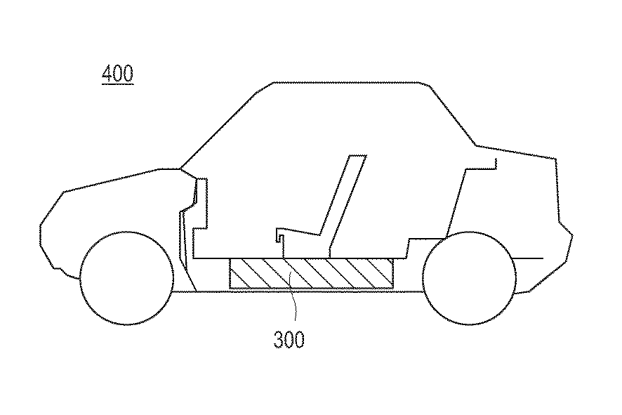
放置後1週間の不良の割合は、比較例では20サンプル中7サンプルであったが、実施例1および2では、1週間後も電圧降下を示したものはなかった。集電体に金属箔を使用した従来の電池では、このような電圧降下はほとんど見られない。上述したように、この電圧降下は高分子材料を含む集電体に生じた微小なクラックにより液絡が生じた結果であることが推定される。したがって、本発明の双極型電極は、このような微小なクラックの影響を効果的に防止すると言える。 The proportion of defects for one week after standing was 7 samples out of 20 in the comparative example, but none of Examples 1 and 2 showed a voltage drop even after one week. In a conventional battery using a metal foil as a current collector, such a voltage drop is hardly seen. As described above, this voltage drop is presumed to be a result of a liquid junction caused by a minute crack generated in the current collector containing the polymer material. Therefore, it can be said that the bipolar electrode of the present invention effectively prevents the influence of such a minute crack.
また、電池の内部抵抗の測定結果から、実施例1の内部抵抗がやや高くなっていることが分かる。これは、集電体が2層になったことで界面に接触抵抗が生じたためと考えられるが、集電体が1層の比較例と比べて実使用上問題のない程度であった。さらに、導電性ペースト層を設けた実施例1では、接触抵抗は大きく低減され、比較例の集電体が1層の場合とほとんど遜色のない性能を示すことが分かる。 Moreover, it turns out that the internal resistance of Example 1 is a little high from the measurement result of the internal resistance of a battery. This is thought to be because contact resistance was generated at the interface due to the current collector having two layers, but the current collector had a practically no problem as compared with the comparative example having one layer. Furthermore, in Example 1 provided with the conductive paste layer, the contact resistance is greatly reduced, and it can be seen that the performance of the current collector of the comparative example is almost the same as that of a single layer.
10 双極型リチウムイオン二次電池、
11、11a、11b、31、35、43、54 集電体、
12、32、36、41、51 正極活物質層、
13、33、37、42、52 負極活物質層、
14 双極型電極
14a 正極側電極
14b 負極側電極
15 電解質層、
16 単電池層、
17 発電要素(電池要素;積層体)、
18 正極タブ、
19 負極タブ、
20 正極端子リード、
21 負極端子リード、
22、47、58 電池外装材
23 絶縁層
34、40、50 高分子材料を含む層、
44、55 セパレータ
45、56 タブ
46、57 シール材
53 導電性ペースト層
250 小型の組電池、
300 組電池、
310 接続治具、
400 電気自動車、
A クラック。
10 Bipolar lithium ion secondary battery,
11, 11a, 11b, 31, 35, 43, 54 current collector,
12, 32, 36, 41, 51 positive electrode active material layer,
13, 33, 37, 42, 52 negative electrode active material layer,
14
16 cell layer,
17 Power generation element (battery element; laminate),
18 positive electrode tab,
19 negative electrode tab,
20 positive terminal lead,
21 negative terminal lead,
22, 47, 58
44, 55
300 battery packs,
310 connection jig,
400 electric car,
A crack.
Claims (9)
前記集電体の一方の面に形成された正極活物質層と、
前記集電体の他方の面に形成された負極活物質層と、
を含む双極型電極。 A current collector consisting of at least two layers containing a polymer material;
A positive electrode active material layer formed on one surface of the current collector;
A negative electrode active material layer formed on the other surface of the current collector;
Including bipolar electrode.
高分子材料を含む第1の層の片面に正極活物質を含むスラリーを塗布し、乾燥し、プレスして正極活物質層を形成する工程と、
高分子材料を含む第2の層の片面に負極活物質を含むスラリーを塗布し、乾燥し、プレスして負極活物質層を形成する工程と、
前記第1の層の正極活物質層を形成していない面と、前記第2の層の負極活物質層を形成していない面とを重ねる工程と、
を含む双極型電極の製造方法。 Providing at least two layers comprising a polymeric material;
Applying a slurry containing a positive electrode active material to one side of the first layer containing a polymer material, drying and pressing to form a positive electrode active material layer;
Applying a slurry containing a negative electrode active material to one side of the second layer containing a polymer material, drying and pressing to form a negative electrode active material layer;
A step of overlapping a surface of the first layer not forming the positive electrode active material layer and a surface of the second layer not forming the negative electrode active material layer;
A method for manufacturing a bipolar electrode including:
Priority Applications (2)
| Application Number | Priority Date | Filing Date | Title |
|---|---|---|---|
| JP2008238045A JP2010073421A (en) | 2008-09-17 | 2008-09-17 | Bipolar electrode and its manufacturing method |
| PCT/JP2009/003672 WO2010032362A1 (en) | 2008-09-17 | 2009-08-03 | Bipolar electrode and production method thereof |
Applications Claiming Priority (1)
| Application Number | Priority Date | Filing Date | Title |
|---|---|---|---|
| JP2008238045A JP2010073421A (en) | 2008-09-17 | 2008-09-17 | Bipolar electrode and its manufacturing method |
Publications (1)
| Publication Number | Publication Date |
|---|---|
| JP2010073421A true JP2010073421A (en) | 2010-04-02 |
Family
ID=42039215
Family Applications (1)
| Application Number | Title | Priority Date | Filing Date |
|---|---|---|---|
| JP2008238045A Pending JP2010073421A (en) | 2008-09-17 | 2008-09-17 | Bipolar electrode and its manufacturing method |
Country Status (2)
| Country | Link |
|---|---|
| JP (1) | JP2010073421A (en) |
| WO (1) | WO2010032362A1 (en) |
Cited By (25)
| Publication number | Priority date | Publication date | Assignee | Title |
|---|---|---|---|---|
| JP2012038426A (en) * | 2010-08-03 | 2012-02-23 | Nissan Motor Co Ltd | Collector for nickel-containing positive electrode |
| JP2013069549A (en) * | 2011-09-22 | 2013-04-18 | Nissan Motor Co Ltd | Bipolar battery |
| JP2014532956A (en) * | 2011-10-25 | 2014-12-08 | エルジー・ケム・リミテッド | Cable type secondary battery |
| WO2016031689A1 (en) * | 2014-08-25 | 2016-03-03 | 日産自動車株式会社 | Electrical connection structure |
| US9300005B2 (en) | 2011-10-13 | 2016-03-29 | Lg Chem, Ltd. | Cable-type secondary battery |
| US9306236B2 (en) | 2011-10-13 | 2016-04-05 | Lg Chem, Ltd. | Cable-type secondary battery |
| US9306237B2 (en) | 2011-10-13 | 2016-04-05 | Lg Chem, Ltd. | Cable-type secondary battery |
| US9356308B2 (en) | 2011-10-13 | 2016-05-31 | Lg Chem, Ltd. | Cable-type secondary battery |
| JP2016162489A (en) * | 2015-02-26 | 2016-09-05 | 株式会社半導体エネルギー研究所 | Flexible lithium ion storage battery and electronic device |
| US9755265B2 (en) | 2011-06-02 | 2017-09-05 | Lg Chem, Ltd. | Anode for secondary battery and secondary battery having the same |
| JP2017533548A (en) * | 2014-11-05 | 2017-11-09 | 24エム・テクノロジーズ・インコーポレイテッド24M Technologies, Inc. | Electrochemical cell having semi-solid electrode and method for producing the same |
| JP2019139915A (en) * | 2018-02-08 | 2019-08-22 | 三洋化成工業株式会社 | Positive electrode for lithium ion battery and lithium ion battery |
| JP2019139914A (en) * | 2018-02-08 | 2019-08-22 | 三洋化成工業株式会社 | Resin current collector, positive electrode for lithium ion battery, and lithium ion battery |
| JP2019212384A (en) * | 2018-05-31 | 2019-12-12 | 三洋化成工業株式会社 | Resin collector and lithium ion battery |
| JP2020009771A (en) * | 2019-08-08 | 2020-01-16 | 株式会社半導体エネルギー研究所 | Lithium ion storage battery |
| CN112186240A (en) * | 2019-07-04 | 2021-01-05 | 宁德新能源科技有限公司 | Electrode assembly and battery having the same |
| US11024903B2 (en) | 2015-06-18 | 2021-06-01 | 24M Technologies, Inc. | Single pouch battery cells and methods of manufacture |
| CN113270589A (en) * | 2021-05-25 | 2021-08-17 | 厦门海辰新能源科技有限公司 | Lithium ion battery, bipolar current collector and manufacturing method thereof |
| US11121437B2 (en) | 2012-05-18 | 2021-09-14 | 24M Technologies, Inc. | Electrochemical cells and methods of manufacturing the same |
| US11309531B2 (en) | 2011-09-07 | 2022-04-19 | 24M Technologies, Inc. | Stationary semi-solid battery module and method of manufacture |
| JP2022062150A (en) * | 2019-08-08 | 2022-04-19 | 株式会社半導体エネルギー研究所 | Lithium ion battery |
| US11742525B2 (en) | 2020-02-07 | 2023-08-29 | 24M Technologies, Inc. | Divided energy electrochemical cell systems and methods of producing the same |
| JP2023132317A (en) * | 2022-03-10 | 2023-09-22 | トヨタ自動車株式会社 | Current collector and secondary battery |
| US12142721B2 (en) | 2014-10-13 | 2024-11-12 | 24M Technologies, Inc. | Methods for battery charging and formation |
| US12381277B2 (en) | 2020-06-17 | 2025-08-05 | 24M Technologies, Inc. | Electrochemical cells with flame retardant mechanism and methods of producing the same |
Families Citing this family (4)
| Publication number | Priority date | Publication date | Assignee | Title |
|---|---|---|---|---|
| CN109585904B (en) * | 2017-09-29 | 2021-11-23 | 辉能科技股份有限公司 | Flexible lithium battery |
| CN115642217B (en) * | 2021-02-24 | 2024-05-24 | 厦门海辰储能科技股份有限公司 | A method for manufacturing a pole piece |
| CN115832451A (en) * | 2022-12-22 | 2023-03-21 | 烯晶碳能电子科技无锡有限公司 | A kind of manufacturing process of multi-component battery |
| CN120937153A (en) * | 2024-03-29 | 2025-11-11 | 厦门新能安科技有限公司 | Bipolar current collector, bipolar pole piece, electrochemical device and electronic device |
Family Cites Families (3)
| Publication number | Priority date | Publication date | Assignee | Title |
|---|---|---|---|---|
| JP2003031261A (en) * | 2001-07-18 | 2003-01-31 | Nissan Motor Co Ltd | Bipolar battery |
| JP2005197217A (en) * | 2003-12-10 | 2005-07-21 | Mitsui Mining & Smelting Co Ltd | Anode for non-aqueous electrolyte secondary battery |
| JP5292676B2 (en) * | 2006-06-07 | 2013-09-18 | 日産自動車株式会社 | Bipolar battery electrode |
-
2008
- 2008-09-17 JP JP2008238045A patent/JP2010073421A/en active Pending
-
2009
- 2009-08-03 WO PCT/JP2009/003672 patent/WO2010032362A1/en not_active Ceased
Cited By (46)
| Publication number | Priority date | Publication date | Assignee | Title |
|---|---|---|---|---|
| JP2012038426A (en) * | 2010-08-03 | 2012-02-23 | Nissan Motor Co Ltd | Collector for nickel-containing positive electrode |
| US9755265B2 (en) | 2011-06-02 | 2017-09-05 | Lg Chem, Ltd. | Anode for secondary battery and secondary battery having the same |
| US11309531B2 (en) | 2011-09-07 | 2022-04-19 | 24M Technologies, Inc. | Stationary semi-solid battery module and method of manufacture |
| US11888144B2 (en) | 2011-09-07 | 2024-01-30 | 24M Technologies, Inc. | Stationary semi-solid battery module and method of manufacture |
| JP2013069549A (en) * | 2011-09-22 | 2013-04-18 | Nissan Motor Co Ltd | Bipolar battery |
| US9306236B2 (en) | 2011-10-13 | 2016-04-05 | Lg Chem, Ltd. | Cable-type secondary battery |
| US9306237B2 (en) | 2011-10-13 | 2016-04-05 | Lg Chem, Ltd. | Cable-type secondary battery |
| US9356308B2 (en) | 2011-10-13 | 2016-05-31 | Lg Chem, Ltd. | Cable-type secondary battery |
| US9300005B2 (en) | 2011-10-13 | 2016-03-29 | Lg Chem, Ltd. | Cable-type secondary battery |
| US9755266B2 (en) | 2011-10-13 | 2017-09-05 | Lg Chem, Ltd. | Cable-type secondary battery |
| JP2014532956A (en) * | 2011-10-25 | 2014-12-08 | エルジー・ケム・リミテッド | Cable type secondary battery |
| US9299987B2 (en) | 2011-10-25 | 2016-03-29 | Lg Chem, Ltd. | Cable-type secondary battery |
| US12068445B2 (en) | 2012-05-18 | 2024-08-20 | 24M Technologies, Inc. | Electrochemical cells and methods of manufacturing the same |
| US11121437B2 (en) | 2012-05-18 | 2021-09-14 | 24M Technologies, Inc. | Electrochemical cells and methods of manufacturing the same |
| US11646437B2 (en) | 2012-05-18 | 2023-05-09 | 24M Technologies, Inc. | Electrochemical cells and methods of manufacturing the same |
| US10312524B2 (en) | 2014-08-25 | 2019-06-04 | Nissan Motor Co., Ltd. | Electrical connection structure |
| WO2016031689A1 (en) * | 2014-08-25 | 2016-03-03 | 日産自動車株式会社 | Electrical connection structure |
| JPWO2016031689A1 (en) * | 2014-08-25 | 2017-07-06 | 日産自動車株式会社 | Electrical connection structure |
| US12142721B2 (en) | 2014-10-13 | 2024-11-12 | 24M Technologies, Inc. | Methods for battery charging and formation |
| US12183909B2 (en) | 2014-11-05 | 2024-12-31 | 24M Technologies, Inc. | Electrochemical cells having semi-solid electrodes and methods of manufacturing the same |
| US10637038B2 (en) | 2014-11-05 | 2020-04-28 | 24M Technologies, Inc. | Electrochemical cells having semi-solid electrodes and methods of manufacturing the same |
| JP2017533548A (en) * | 2014-11-05 | 2017-11-09 | 24エム・テクノロジーズ・インコーポレイテッド24M Technologies, Inc. | Electrochemical cell having semi-solid electrode and method for producing the same |
| US10886521B2 (en) | 2014-11-05 | 2021-01-05 | 24M Technologies, Inc. | Electrochemical cells having semi-solid electrodes and methods of manufacturing the same |
| US11611061B2 (en) | 2014-11-05 | 2023-03-21 | 24M Technologies, Inc. | Electrochemical cells having semi-solid electrodes and methods of manufacturing the same |
| JP2016162489A (en) * | 2015-02-26 | 2016-09-05 | 株式会社半導体エネルギー研究所 | Flexible lithium ion storage battery and electronic device |
| US11024903B2 (en) | 2015-06-18 | 2021-06-01 | 24M Technologies, Inc. | Single pouch battery cells and methods of manufacture |
| US11831026B2 (en) | 2015-06-18 | 2023-11-28 | 24M Technologies, Inc. | Single pouch battery cells and methods of manufacture |
| US12347874B2 (en) | 2015-06-18 | 2025-07-01 | 24M Technologies, Inc. | Single pouch battery cells and methods of manufacture |
| JP7042640B2 (en) | 2018-02-08 | 2022-03-28 | 三洋化成工業株式会社 | Resin collector, positive electrode for lithium-ion battery, and lithium-ion battery |
| JP7007944B2 (en) | 2018-02-08 | 2022-01-25 | 三洋化成工業株式会社 | Positive electrode for lithium-ion batteries and lithium-ion batteries |
| JP2019139915A (en) * | 2018-02-08 | 2019-08-22 | 三洋化成工業株式会社 | Positive electrode for lithium ion battery and lithium ion battery |
| JP2019139914A (en) * | 2018-02-08 | 2019-08-22 | 三洋化成工業株式会社 | Resin current collector, positive electrode for lithium ion battery, and lithium ion battery |
| JP7148277B2 (en) | 2018-05-31 | 2022-10-05 | 三洋化成工業株式会社 | Resin current collector and lithium ion battery |
| JP2019212384A (en) * | 2018-05-31 | 2019-12-12 | 三洋化成工業株式会社 | Resin collector and lithium ion battery |
| US11508993B2 (en) | 2019-07-04 | 2022-11-22 | Ningde Amperex Technology Ltd. | Electrode assembly having an electrode subassembly, and battery including the electrode assembly |
| CN112186240A (en) * | 2019-07-04 | 2021-01-05 | 宁德新能源科技有限公司 | Electrode assembly and battery having the same |
| CN112186240B (en) * | 2019-07-04 | 2022-02-22 | 宁德新能源科技有限公司 | Electrode assembly and battery having the same |
| JP2020009771A (en) * | 2019-08-08 | 2020-01-16 | 株式会社半導体エネルギー研究所 | Lithium ion storage battery |
| JP7259100B2 (en) | 2019-08-08 | 2023-04-17 | 株式会社半導体エネルギー研究所 | lithium ion storage battery |
| JP2022062150A (en) * | 2019-08-08 | 2022-04-19 | 株式会社半導体エネルギー研究所 | Lithium ion battery |
| US11742525B2 (en) | 2020-02-07 | 2023-08-29 | 24M Technologies, Inc. | Divided energy electrochemical cell systems and methods of producing the same |
| US12362398B2 (en) | 2020-02-07 | 2025-07-15 | 24M Technologies, Inc. | Divided energy electrochemical cell systems and methods of producing the same |
| US12381277B2 (en) | 2020-06-17 | 2025-08-05 | 24M Technologies, Inc. | Electrochemical cells with flame retardant mechanism and methods of producing the same |
| CN113270589A (en) * | 2021-05-25 | 2021-08-17 | 厦门海辰新能源科技有限公司 | Lithium ion battery, bipolar current collector and manufacturing method thereof |
| JP2023132317A (en) * | 2022-03-10 | 2023-09-22 | トヨタ自動車株式会社 | Current collector and secondary battery |
| JP7704700B2 (en) | 2022-03-10 | 2025-07-08 | トヨタ自動車株式会社 | Current collector and secondary battery |
Also Published As
| Publication number | Publication date |
|---|---|
| WO2010032362A1 (en) | 2010-03-25 |
Similar Documents
| Publication | Publication Date | Title |
|---|---|---|
| JP2010073421A (en) | Bipolar electrode and its manufacturing method | |
| JP6299773B2 (en) | Method for producing non-aqueous electrolyte secondary battery | |
| US10177387B2 (en) | Bipolar battery current collector that contracts to interrupt a flow of electric current in a direction thereof and bipolar battery | |
| JP5333576B2 (en) | Bipolar secondary battery and manufacturing method thereof | |
| US8076021B2 (en) | Bipolar battery | |
| JP5200367B2 (en) | Bipolar battery electrode | |
| JP6573250B2 (en) | Method for producing non-aqueous electrolyte secondary battery | |
| JP2011029075A (en) | Negative electrode for lithium ion secondary battery, and lithium ion secondary battery using the same | |
| JP2006190649A (en) | Bipolar battery and manufacturing method thereof | |
| JP2012009209A (en) | Negative electrode for lithium ion secondary battery | |
| JP2008097940A (en) | Bipolar secondary battery | |
| JP5401756B2 (en) | Secondary battery | |
| JP5392328B2 (en) | Solid electrolyte battery | |
| JP5292676B2 (en) | Bipolar battery electrode | |
| JP2007109636A (en) | Battery electrode | |
| JP2009252497A (en) | Electrode for battery and battery | |
| JP5023428B2 (en) | Solid electrolyte battery | |
| JP2010157449A (en) | Bipolar electrode, and bipolar battery using the same | |
| JP2015128020A (en) | Bipolar secondary battery, bipolar secondary battery module, and method for manufacturing bipolar secondary battery | |
| JP4984448B2 (en) | Manufacturing method of secondary battery | |
| JP2007280687A (en) | Battery electrode | |
| JP5326450B2 (en) | Electrode and manufacturing method thereof | |
| JP2005174844A (en) | Bipolar battery | |
| JP2006172995A (en) | Electrode ink and battery | |
| JP4433783B2 (en) | Bipolar battery |