JP2017527835A - Directional privacy display - Google Patents
Directional privacy display Download PDFInfo
- Publication number
- JP2017527835A JP2017527835A JP2016570259A JP2016570259A JP2017527835A JP 2017527835 A JP2017527835 A JP 2017527835A JP 2016570259 A JP2016570259 A JP 2016570259A JP 2016570259 A JP2016570259 A JP 2016570259A JP 2017527835 A JP2017527835 A JP 2017527835A
- Authority
- JP
- Japan
- Prior art keywords
- light
- primary
- image
- waveguide
- display device
- Prior art date
- Legal status (The legal status is an assumption and is not a legal conclusion. Google has not performed a legal analysis and makes no representation as to the accuracy of the status listed.)
- Granted
Links
Images


Classifications
-
- G—PHYSICS
- G02—OPTICS
- G02B—OPTICAL ELEMENTS, SYSTEMS OR APPARATUS
- G02B6/00—Light guides; Structural details of arrangements comprising light guides and other optical elements, e.g. couplings
- G02B6/0001—Light guides; Structural details of arrangements comprising light guides and other optical elements, e.g. couplings specially adapted for lighting devices or systems
- G02B6/0011—Light guides; Structural details of arrangements comprising light guides and other optical elements, e.g. couplings specially adapted for lighting devices or systems the light guides being planar or of plate-like form
- G02B6/0033—Means for improving the coupling-out of light from the light guide
- G02B6/0035—Means for improving the coupling-out of light from the light guide provided on the surface of the light guide or in the bulk of it
- G02B6/0045—Means for improving the coupling-out of light from the light guide provided on the surface of the light guide or in the bulk of it by shaping at least a portion of the light guide
- G02B6/0046—Tapered light guide, e.g. wedge-shaped light guide
- G02B6/0048—Tapered light guide, e.g. wedge-shaped light guide with stepwise taper
-
- G—PHYSICS
- G02—OPTICS
- G02B—OPTICAL ELEMENTS, SYSTEMS OR APPARATUS
- G02B30/00—Optical systems or apparatus for producing three-dimensional [3D] effects, e.g. stereoscopic images
- G02B30/20—Optical systems or apparatus for producing three-dimensional [3D] effects, e.g. stereoscopic images by providing first and second parallax images to an observer's left and right eyes
- G02B30/26—Optical systems or apparatus for producing three-dimensional [3D] effects, e.g. stereoscopic images by providing first and second parallax images to an observer's left and right eyes of the autostereoscopic type
- G02B30/33—Optical systems or apparatus for producing three-dimensional [3D] effects, e.g. stereoscopic images by providing first and second parallax images to an observer's left and right eyes of the autostereoscopic type involving directional light or back-light sources
-
- G—PHYSICS
- G02—OPTICS
- G02B—OPTICAL ELEMENTS, SYSTEMS OR APPARATUS
- G02B6/00—Light guides; Structural details of arrangements comprising light guides and other optical elements, e.g. couplings
- G02B6/0001—Light guides; Structural details of arrangements comprising light guides and other optical elements, e.g. couplings specially adapted for lighting devices or systems
- G02B6/0011—Light guides; Structural details of arrangements comprising light guides and other optical elements, e.g. couplings specially adapted for lighting devices or systems the light guides being planar or of plate-like form
- G02B6/0066—Light guides; Structural details of arrangements comprising light guides and other optical elements, e.g. couplings specially adapted for lighting devices or systems the light guides being planar or of plate-like form characterised by the light source being coupled to the light guide
- G02B6/0068—Arrangements of plural sources, e.g. multi-colour light sources
-
- G—PHYSICS
- G02—OPTICS
- G02F—OPTICAL DEVICES OR ARRANGEMENTS FOR THE CONTROL OF LIGHT BY MODIFICATION OF THE OPTICAL PROPERTIES OF THE MEDIA OF THE ELEMENTS INVOLVED THEREIN; NON-LINEAR OPTICS; FREQUENCY-CHANGING OF LIGHT; OPTICAL LOGIC ELEMENTS; OPTICAL ANALOGUE/DIGITAL CONVERTERS
- G02F1/00—Devices or arrangements for the control of the intensity, colour, phase, polarisation or direction of light arriving from an independent light source, e.g. switching, gating or modulating; Non-linear optics
- G02F1/01—Devices or arrangements for the control of the intensity, colour, phase, polarisation or direction of light arriving from an independent light source, e.g. switching, gating or modulating; Non-linear optics for the control of the intensity, phase, polarisation or colour
- G02F1/13—Devices or arrangements for the control of the intensity, colour, phase, polarisation or direction of light arriving from an independent light source, e.g. switching, gating or modulating; Non-linear optics for the control of the intensity, phase, polarisation or colour based on liquid crystals, e.g. single liquid crystal display cells
- G02F1/1323—Arrangements for providing a switchable viewing angle
-
- H—ELECTRICITY
- H04—ELECTRIC COMMUNICATION TECHNIQUE
- H04N—PICTORIAL COMMUNICATION, e.g. TELEVISION
- H04N13/00—Stereoscopic video systems; Multi-view video systems; Details thereof
- H04N13/30—Image reproducers
- H04N13/302—Image reproducers for viewing without the aid of special glasses, i.e. using autostereoscopic displays
- H04N13/32—Image reproducers for viewing without the aid of special glasses, i.e. using autostereoscopic displays using arrays of controllable light sources; using moving apertures or moving light sources
-
- G—PHYSICS
- G02—OPTICS
- G02B—OPTICAL ELEMENTS, SYSTEMS OR APPARATUS
- G02B6/00—Light guides; Structural details of arrangements comprising light guides and other optical elements, e.g. couplings
- G02B6/0001—Light guides; Structural details of arrangements comprising light guides and other optical elements, e.g. couplings specially adapted for lighting devices or systems
- G02B6/0011—Light guides; Structural details of arrangements comprising light guides and other optical elements, e.g. couplings specially adapted for lighting devices or systems the light guides being planar or of plate-like form
- G02B6/0033—Means for improving the coupling-out of light from the light guide
- G02B6/005—Means for improving the coupling-out of light from the light guide provided by one optical element, or plurality thereof, placed on the light output side of the light guide
- G02B6/0055—Reflecting element, sheet or layer
-
- H—ELECTRICITY
- H04—ELECTRIC COMMUNICATION TECHNIQUE
- H04N—PICTORIAL COMMUNICATION, e.g. TELEVISION
- H04N13/00—Stereoscopic video systems; Multi-view video systems; Details thereof
- H04N13/30—Image reproducers
- H04N2013/40—Privacy aspects, i.e. devices showing different images to different viewers, the images not being viewpoints of the same scene
- H04N2013/405—Privacy aspects, i.e. devices showing different images to different viewers, the images not being viewpoints of the same scene the images being stereoscopic or three dimensional
Landscapes
- Physics & Mathematics (AREA)
- General Physics & Mathematics (AREA)
- Optics & Photonics (AREA)
- Nonlinear Science (AREA)
- Chemical & Material Sciences (AREA)
- Signal Processing (AREA)
- Engineering & Computer Science (AREA)
- Crystallography & Structural Chemistry (AREA)
- Multimedia (AREA)
- Liquid Crystal (AREA)
- Control Of Indicators Other Than Cathode Ray Tubes (AREA)
- Planar Illumination Modules (AREA)
- Liquid Crystal Display Device Control (AREA)
- Devices For Indicating Variable Information By Combining Individual Elements (AREA)
Abstract
指向性プライバシーディスプレイは、導波管、並びに光源のアレイ及び時系列的に作動する空間光変調器を有することができる。導波管は、光源のアレイからの光を全内部反射により視野窓のアレイに方向付けるように配置された光抽出要素と、導波管からの光を導波管の抽出要素を透過することにより同じ視野窓のアレイへと方向付けるように配置されたリフレクターとを含むことができる。第1及び第2の位相はそれぞれの一次及び二次画像並びに一次及び二次角度照明分布と時間的に多重化することができる。軸外観測者に対する一次画像の視認性が不明瞭化された、効率的で明るいプライバシーディスプレイを提供することができる。A directional privacy display can have a waveguide and an array of light sources and a spatial light modulator operating in time series. The waveguide transmits light from the array of light sources through the waveguide extraction element, and a light extraction element arranged to direct light from the array of light sources to the array of viewing windows by total internal reflection. And reflectors arranged to direct to the same array of viewing windows. The first and second phases can be temporally multiplexed with respective primary and secondary images and primary and secondary angular illumination distributions. An efficient and bright privacy display in which the visibility of the primary image to the off-axis observer is obscured can be provided.
Description
(関連出願の相互参照)
本出願は、2011年11月18日出願の米国特許出願第13/300,293号、「Directional flat illuminators」(代理人整理番号95194936.281001)、2013年3月15日出願の米国特許出願第13/836,443号、「Crosstalk suppression in a directional backlight」(代理人整理番号95194936.317001)、2014年2月21日出願の米国特許出願第14/186,862号、「Directional backlight」(代理人整理番号95194936.355001)、2015年5月27日出願の発明の名称が「Wide angle imaging directional backlights」である米国特許仮出願第62/167203号(代理人整理番号384000)、2015年5月27日出願の発明の名称が「Wide angle imaging directional backlights」である米国特許仮出願第62/167,185号(代理人整理番号379000B)に関するものであり、これらの出願のすべてを本明細書にその全容にわたって参照により援用するものである。更に、本出願は、2014年6月26日出願の発明の名称が「Directional privacy display」である米国特許仮出願第62/017337号(代理人整理番号373000)に関し、当該出願に基づく優先権を主張するものである。
(Cross-reference of related applications)
This application is based on US Patent Application No. 13 / 300,293, filed November 18, 2011, “Directional flat illuminators” (Attorney Docket No. 95194936.281001), US Patent Application No. 15/15/2013. 13 / 836,443, “Crosstal suppression in a direct backlight” (Attorney Docket No. 95194936.317001), US Patent Application No. 14 / 186,862, filed February 21, 2014, “Directive backlight” (Attorney) (Invention number 95194936.355001), the name of the invention filed on May 27, 2015 is "Wide angle imaging directive backlight" US Provisional Application No. 62/167203 (Attorney Docket No. 384000), US Patent Provisional Application No. 62/167, whose title is “Wide angle imaging directive backlights”, filed on May 27, 2015. No. 185 (Attorney Docket No. 379000B), all of which are hereby incorporated by reference in their entirety. Furthermore, this application relates to US Patent Provisional Application No. 62/017337 (Attorney Docket No. 373000) filed on June 26, 2014, whose title is “Directional privacy display”. It is what I insist.
(発明の分野)
本開示は一般的には光変調装置の照明に関し、より詳細にはプライバシーディスプレイ機器において使用するための局所光源から広範囲の照明をもたらすための光ガイドに関する。
(Field of Invention)
The present disclosure relates generally to lighting of light modulation devices, and more particularly to a light guide for providing a wide range of lighting from a local light source for use in a privacy display device.
空間的に多重化された自動立体視ディスプレイは、典型的には、例えばLCDなどの空間光変調器上に少なくとも第1の画素群及び第2の画素群として配列された画像のアレイに、レンチキュラースクリーン、又は視差バリアなどの視差要素を整列させる。視差要素は、各画素群からの光を、異なるそれぞれの方向に方向付けて、ディスプレイの正面に第1の視野窓及び第2の視野窓を提供する。片方の目が第1の視野窓に置かれた観測者には、第1の画素群からの光による第1の像が見え、片方の目が第2の視野窓に置かれた場合には第2の画像群からの光による第2の像が見える。 A spatially multiplexed autostereoscopic display typically includes a lenticular array of images arranged as at least a first pixel group and a second pixel group on a spatial light modulator such as an LCD. Align parallax elements such as screens or parallax barriers. The parallax element directs light from each pixel group in different respective directions to provide a first field window and a second field window in front of the display. An observer with one eye placed in the first field window sees the first image from light from the first pixel group, and one eye is placed in the second field window. A second image with light from the second image group is visible.
こうしたディスプレイは、空間光変調器の本来の解像度と比較して空間解像度が低く、更に視野窓の構造は、画素の開口形状及び視差要素の結像機能によって決定される。画素間に、例えば電極用の空隙があると、典型的には、不均一な視野窓を生じる。こうしたディスプレイでは、ディスプレイに対して横方向に観測者が動くと画像のフリッカが生じることにより、ディスプレイの視覚的自由度が制限されるために望ましくない。こうしたフリッカは、光学素子の焦点をずらすことによって低減させることができるが、このように焦点をずらすと像のクロストークのレベルが高くなり、観測者の視覚疲労が増す。このようなフリッカは、画素の開口部の形状を調整することで低減できるが、こうした変更は、ディスプレイの輝度を低下させ得るものであり、空間光変調器内の電子機器のアドレスを指定することを含む。 Such a display has a lower spatial resolution than the original resolution of the spatial light modulator, and the structure of the viewing window is determined by the aperture shape of the pixel and the imaging function of the parallax element. Any gap between pixels, for example for electrodes, typically results in a non-uniform viewing window. Such a display is undesirable because the viewer's visual freedom is limited by the flickering of the image that occurs when the observer moves laterally relative to the display. Such flicker can be reduced by shifting the focus of the optical element, but shifting the focus in this way increases the level of image crosstalk and increases the visual fatigue of the observer. Such flicker can be reduced by adjusting the shape of the pixel aperture, but such changes can reduce the brightness of the display and specify the address of the electronics in the spatial light modulator. including.
更に、空間的に多重化されたディスプレイは、指向性画像の繰返しローブを与えることにより、軸外の可視性が維持されるために、プライバシーディスプレイには典型的に向いていない。 Furthermore, spatially multiplexed displays are typically not suitable for privacy displays because off-axis visibility is maintained by providing repeated lobes of directional images.
本開示の第1の態様によれば、指向性ディスプレイ装置であって、指向性バックライトであって、導波管に沿って入力光を案内するための第1のガイド面及び反対側の第2のガイド面を有する導波管と、導波管にわたって複数の異なる入力位置において入力光を生成するように配置された光源のアレイとを有し、第1のガイド面は全内部反射によって光を案内するように配置されており、第2のガイド面は、導波管を通じて案内された光を第1のガイド面を通って出力光として導波管の外部に偏向するように配置された複数の光抽出要素と、前記導波管に沿って光を案内するように配置された、光抽出要素の間の複数の中間領域とを含み、導波管が、前記出力光を、前記入力光の入力位置に応じて横方向に分配された複数の出力方向において複数の光学窓内へと方向付けるように配置されている、指向性バックライトと、前記導波管の前記第1のガイド面からの前記出力光を受光し、これを変調して画像を表示するように配置された透過型空間光変調器と、前記空間光変調器を制御することが可能であり、かつ光を対応する複数の光学窓内に方向付けるように、複数の光源を選択的に作動させることが可能である制御システムであって、前記指向性バックライト内の迷光が、選択的に作動される複数の光源に対応する前記複数の光学窓の外側の複数の出力方向に方向付けられる、制御システムとを備え、前記制御システムは、前記空間光変調器と前記光源のアレイとを互いに同期して制御するように配置され、これにより、(a)一次観測者に見えるように、少なくとも1つの一次光源が少なくとも1つの一次光学窓内に光を方向付けるように選択的に作動される間に前記空間光変調器が一次画像を表示し、(b)前記少なくとも1つの一次光源以外の少なくとも1つの光源が前記少なくとも1つの一次光学窓の外側の複数の二次光学窓内に光を方向付けるように選択的に作動される間に、前記一次画像の表示と時間的に多重化された方式で、前記空間光変調器が二次画像を表示し、前記一次光学窓の外側の二次観測者によって知覚される前記二次画像が、前記一次光学窓の外側に方向付けられた前記迷光を変調する一次画像を不明瞭化する、指向性ディスプレイ装置が提供され得る。 According to a first aspect of the present disclosure, there is a directional display device, a directional backlight, a first guide surface for guiding input light along a waveguide, and a first guide surface on the opposite side. A waveguide having two guide surfaces and an array of light sources arranged to generate input light at a plurality of different input positions across the waveguide, the first guide surface being light by total internal reflection The second guide surface is disposed so as to deflect the light guided through the waveguide to the outside of the waveguide as output light through the first guide surface. A plurality of light extraction elements and a plurality of intermediate regions between the light extraction elements arranged to guide light along the waveguide, wherein the waveguide receives the output light as the input In multiple output directions distributed laterally according to the light input position A directional backlight arranged to direct into a number of optical windows and the output light from the first guide surface of the waveguide are received and modulated to display an image A transmissive spatial light modulator arranged in such a manner that a plurality of light sources can be selectively controlled to control the spatial light modulator and direct light into a corresponding plurality of optical windows A stray light in the directional backlight directed in a plurality of output directions outside the plurality of optical windows corresponding to the plurality of selectively activated light sources. A control system, wherein the control system is arranged to control the spatial light modulator and the array of light sources in synchronization with each other, thereby (a) visible to the primary observer At least one primary The spatial light modulator displays a primary image while the source is selectively actuated to direct light into at least one primary optical window, and (b) at least one other than the at least one primary light source. In a time multiplexed manner with the display of the primary image while a light source is selectively actuated to direct light into a plurality of secondary optical windows outside the at least one primary optical window. The spatial light modulator displays a secondary image, and the secondary image perceived by a secondary observer outside the primary optical window modulates the stray light directed outside the primary optical window. A directional display device can be provided that obfuscates the primary image to be obscured.
これにより、ディスプレイは、快適な視野範囲にわたって一次観測者に高い輝度及び高いコントラストで一次画像を提供することができる。視野範囲の外側の二次観測者は、一次画像よりも低い輝度で二次画像を観測することができ、更に、低減されたコントラスト、妨害パターン、又は他の不明瞭化効果を有する。有利なことには、所望の一次画像は二次観測者が知覚することが困難となるため、公共の環境でのディスプレイの使用のセキュリティーを向上させることができる。更に、ディスプレイ表面からの反射が二次観測者に対して画像を更に不明瞭化することができる。かかるディスプレイは、広角視野モードとプライバシーモードとの間で切り換わるように配置することができる。更にかかるディスプレイは、電池の充電と充電の間で長時間にわたって低電力での作動を実現することができる。超高輝度モードを広角モード作動とほぼ同じ電力消費量で低い角度範囲にわたって提供することができる。更に、かかるディスプレイは自動立体視ディスプレイ作動を実現するように配置することができる。 Thereby, the display can provide a primary image with high brightness and high contrast to the primary observer over a comfortable visual field range. A secondary observer outside the field of view can observe the secondary image at a lower brightness than the primary image, and also has reduced contrast, disturbing patterns, or other obscuring effects. Advantageously, the security of use of the display in a public environment can be improved because the desired primary image is difficult for the secondary observer to perceive. Furthermore, reflections from the display surface can further obscure the image to secondary observers. Such a display can be arranged to switch between wide-angle viewing mode and privacy mode. Furthermore, such a display can be operated at low power over a long period of time between battery charges. An ultra-bright mode can be provided over a low angular range with approximately the same power consumption as wide-angle mode operation. Furthermore, such a display can be arranged to achieve autostereoscopic display operation.
少なくとも1つの一次光学窓の外側の複数の二次光学窓内に光を方向付けるように選択的に作動される少なくとも1つの一次光源以外の前記少なくとも1つの光源は、少なくとも1つの一次光源以外の複数の光源を含むことができる。少なくとも1つの一次光源以外の前記複数の光源は、異なる光束を有する光を出力するように選択的に作動させることができる。制御システムは、空間光変調器と光源のアレイとを互いに同期して制御するように配置され、これにより、(a)空間光変調器が一次画像を表示する間に、少なくとも1つの一次光源に加えて少なくとも1つの追加の光源が追加の光学窓内に光を方向付けるように選択的に作動され、(b)空間光変調器が二次画像を表示する間に、複数の光源が少なくとも1つの追加の光源及び複数の他の光源を含み、追加の光源が複数の他の光源よりも光度の高い光束の光を出力するように作動される。少なくとも1つの追加の光源は、複数の異なる時間的動作位相で変化し得る。有利なことには、軸外観測者に対するディスプレイの見え方は、一次画像の見え方を妨害する空間光変調器にわたって輝度の異なる領域を含むことができる。このような妨害効果は画像コンテンツを変化させることなく実現することができ、時間によって変化し得る。したがって、一次観測者は、残留二次画像の視認性が最小限に抑えられた状態で一次画像を見ることができる。 The at least one light source other than the at least one primary light source selectively activated to direct light into a plurality of secondary optical windows outside the at least one primary optical window is other than at least one primary light source. Multiple light sources can be included. The plurality of light sources other than the at least one primary light source can be selectively activated to output light having different light fluxes. The control system is arranged to control the spatial light modulator and the array of light sources synchronously with each other so that (a) the at least one primary light source is displayed while the spatial light modulator displays the primary image. In addition, at least one additional light source is selectively activated to direct light into the additional optical window, and (b) the plurality of light sources is at least one while the spatial light modulator displays the secondary image. Including one additional light source and a plurality of other light sources, wherein the additional light source is activated to output a luminous flux of light that is higher in intensity than the plurality of other light sources. The at least one additional light source may change at a plurality of different temporal operating phases. Advantageously, the appearance of the display to off-axis observers can include regions of different brightness across the spatial light modulator that interfere with the appearance of the primary image. Such a disturbing effect can be realized without changing the image content and can change with time. Therefore, the primary observer can see the primary image in a state where the visibility of the residual secondary image is minimized.
二次画像は、一次観測者によって知覚される際、一次光学窓の外側に方向付けられる迷光を変調する一次画像を少なくとも部分的に打ち消すように配置された一次画像の反転コピーを含むことができる。 The secondary image can include an inverted copy of the primary image arranged to at least partially cancel the primary image that modulates stray light directed outside the primary optical window when perceived by the primary observer. .
有利なことには、二次観測者によって知覚される画像は、一次観測者によって知覚される一次画像と比較して大幅に低減されたコントラストを有することができる。 Advantageously, the image perceived by the secondary observer can have a significantly reduced contrast compared to the primary image perceived by the primary observer.
制御システムは、二次画像が一次光学窓の外側に方向付けられる迷光を変調する一次画像と同じ輝度を有するように空間光変調器及び光源のアレイを制御するように配置することができる。一次画像の反転コピーは、画像にわたって空間的に変化する反転関数によって反転された一次画像のコピーを含むことができる。反転関数は、出力窓輝度の空間的変化に応じて画像にわたって空間的に変化し得る。 The control system can be arranged to control the spatial light modulator and the array of light sources so that the secondary image has the same brightness as the primary image that modulates stray light directed outside the primary optical window. An inverted copy of the primary image can include a copy of the primary image that has been inverted by an inversion function that varies spatially across the image. The inversion function can vary spatially across the image in response to a spatial change in output window brightness.
二次画像は、妨害パターンが重ね合わされた一次画像の反転コピーを含むことができる。二次画像は、妨害パターンを含むことができる。一次画像は、一次観測者によって知覚される際、二次光学窓の外側に方向付けられる迷光を変調する妨害パターンを少なくとも部分的に打ち消すように配置された妨害パターンの反転コピーが重ね合わされた一次観測者に対して表示するための画像を含むことができる。 The secondary image can include an inverted copy of the primary image overlaid with the disturbing pattern. The secondary image can include an interference pattern. When the primary image is perceived by the primary observer, the primary image is superimposed with an inverted copy of the interference pattern arranged to at least partially cancel the interference pattern that modulates stray light directed outside the secondary optical window. An image for display to the observer can be included.
有利なことには、不明瞭化効果を、低減された輝度、低減されたコントラスト、及び一次画像コンテンツに依存し得る妨害画像コンテンツと組み合わせることによって、空間光変調器のコントラストの角度変化のために一次画像及び二次画像の打ち消しが完全でない複数の領域において更なる不明瞭化を与えることができる。 Advantageously, for the angular change of the contrast of the spatial light modulator by combining the obscuring effect with reduced brightness, reduced contrast, and disturbing image content that may depend on the primary image content. Further obscuration can be provided in regions where the cancellation of the primary and secondary images is not complete.
制御システムは、空間光変調器と光源のアレイとを互いに同期して制御するように配置され、これにより、空間光変調器が一次画像及び二次画像を不均等な長さの複数の時間スロットで時間的に多重化された方式で表示することができる。 The control system is arranged to control the spatial light modulator and the array of light sources in synchronization with each other, whereby the spatial light modulator allows the primary image and the secondary image to have a plurality of time slots of unequal length. Can be displayed in a time multiplexed manner.
有利なことには、一次画像の輝度を、複数の時間スロットが均等な長さである配置と比較して高めることができる。 Advantageously, the brightness of the primary image can be increased compared to an arrangement where the time slots are of equal length.
空間光変調器は画素のアレイを含むものとすることができ、制御システムは、画素の所望のグレーレベル及び画素の予想されるヒステリシスを考慮して空間光変調器を制御することにより、一次及び二次画像の時間的に多重化された表示の間に各画素の駆動レベルを制御するように配置され得る。 The spatial light modulator may include an array of pixels, and the control system controls the primary and secondary by controlling the spatial light modulator taking into account the desired gray level of the pixel and the expected hysteresis of the pixel. It can be arranged to control the drive level of each pixel during the temporally multiplexed display of the image.
有利なことには、一次画像内への二次画像の漏れを低減させることによって、例えば、一次観測者に対する一次画像内の二次画像から妨害パターンの見え方を低減させることができる。 Advantageously, by reducing the leakage of the secondary image into the primary image, for example, the appearance of the disturbing pattern from the secondary image in the primary image to the primary observer can be reduced.
一次画像は2次元画像であり得る。一次画像は左目画像と右目画像とを含む3次元画像であってよく、制御システムは、(a1)空間光変調器を制御して左目画像及び右目画像を時間的に多重化された方式で表示し、かつ(a2)空間光変調器が左目画像及び右目画像をそれぞれ表示する際、空間光変調器の制御と同期して光源のアレイを制御することで異なる一次光源を選択的に作動させて一次観測者の左目及び右目に見えるように少なくとも1つの一次光学窓内に光を方向付けることにより、空間光変調器を制御して一次画像を表示するように配置され得る。二次画像は2次元画像であり得る。 The primary image can be a two-dimensional image. The primary image may be a three-dimensional image including a left eye image and a right eye image, and the control system (a1) controls the spatial light modulator to display the left eye image and the right eye image in a temporally multiplexed manner. And (a2) when the spatial light modulator displays the left eye image and the right eye image, respectively, by controlling the array of light sources in synchronization with the control of the spatial light modulator, different primary light sources are selectively operated. The spatial light modulator may be arranged to control and display the primary image by directing light into the at least one primary optical window so as to be visible to the left and right eyes of the primary observer. The secondary image can be a two-dimensional image.
有利なことには、二次観測者に対する自動立体視画像の視認性を低くした状態でプライバシーモードにおいて自動立体視作動を実現することができる。 Advantageously, autostereoscopic operation can be achieved in privacy mode with reduced visibility of autostereoscopic images for secondary observers.
第2のガイド面は、光抽出要素である複数のファセット面と複数の中間領域とを含む段差付き形状を有する。指向性バックライトは、導波管の複数のファセット面を通り、導波管を通じて戻る方向に透過して第1のガイド面を通って複数の光学窓内へと出射する複数の光源からの光を反射するように配置された複数の反射ファセット面の線形アレイを含む後方リフレクターを更に有することができる。複数の光抽出要素は、横方向に正の屈折力を有することができる。 The second guide surface has a stepped shape including a plurality of facet surfaces that are light extraction elements and a plurality of intermediate regions. The directional backlight transmits light from a plurality of light sources that passes through a plurality of facet surfaces of a waveguide, transmits in a direction returning through the waveguide, and exits into a plurality of optical windows through a first guide surface. Can further include a rear reflector including a linear array of a plurality of reflective facet surfaces arranged to reflect. The plurality of light extraction elements can have a positive refractive power in the lateral direction.
有利なことには、高輝度、高効率でコンパクトなバックライトを指向性プライバシーディスプレイ用に提供することができる。複数の光源のアレイの制御によって、かかるバックライトは、低電力、高輝度、自動立体視、及びプライバシー作動を含む制御可能な作動モードを実現することができる。 Advantageously, a high brightness, high efficiency and compact backlight can be provided for a directional privacy display. By controlling an array of multiple light sources, such a backlight can achieve controllable operating modes including low power, high brightness, autostereoscopic, and privacy operations.
導波管は入力端を更に有してもよく、入力端に沿って光源のアレイが配置される。導波管は、入力光を導波管を通じて戻るように反射するための反射端を更に有してもよく、第2のガイド面は、反射端からの反射後に光を第1のガイド面からの出力光として偏向するように配置される。反射端は、横方向に正の屈折力を有することができる。導波管は、横方向に細長い反射端を更に有することができ、第1及び第2のガイド面が反射端の横方向に延びる縁部から延び、導波管は第1のガイド面と第2のガイド面との間に延びる複数の側面を更に有し、複数の光源は、側面を通過する入力光を与えるために1つの側面に沿って配置された光源のアレイを含んでもよく、反射端は、横方向に互いに交互に配された第1及び第2のファセット面を含み、第1のファセット面が反射性であり、横方向に正の屈折力を有するフレネルリフレクターの複数の反射ファセット面を形成し、第2のファセット面がフレネルリフレクターの複数のドラフトファセット面を形成し、フレネルリフレクターは、フレネルリフレクターが光源のアレイからの入力光を導波管内に偏向する方向に側面に向かって傾斜した光学軸を有する。 The waveguide may further have an input end, and an array of light sources is disposed along the input end. The waveguide may further include a reflection end for reflecting input light back through the waveguide, and the second guide surface reflects light from the first guide surface after reflection from the reflection end. Are arranged so as to be deflected as output light. The reflection end can have a positive refractive power in the lateral direction. The waveguide may further have a laterally elongated reflective end, the first and second guide surfaces extending from a laterally extending edge of the reflective end, and the waveguide is connected to the first guide surface and the first guide surface. A plurality of side surfaces extending between the two guide surfaces, wherein the plurality of light sources may include an array of light sources disposed along one side to provide input light passing through the side surfaces; A plurality of reflective facets of a Fresnel reflector, the end including first and second facet surfaces alternately arranged in the lateral direction, the first facet surface being reflective and having a positive refractive power in the lateral direction A second facet surface forming a plurality of draft facet surfaces of the Fresnel reflector, the Fresnel reflector facing the side in a direction in which the Fresnel reflector deflects input light from the array of light sources into the waveguide Having oblique to optical axis.
指向性ディスプレイ装置は、一次観測者の頭部の位置を検出するように配置されたセンサーシステムを更に備えてもよく、制御システムは観測者の頭部の検出された位置にしたがって複数の光源を制御するように配置される。 The directional display device may further comprise a sensor system arranged to detect the position of the primary observer's head, and the control system provides a plurality of light sources according to the detected position of the observer's head. Arranged to control.
有利なことには、一次観測者の動きの自由度を高めることができ、二次観測者が一次画像を見ようとする範囲を狭めることができる。 Advantageously, the degree of freedom of movement of the primary observer can be increased and the range over which the secondary observer can see the primary image can be narrowed.
センサーシステムは、一次光学窓の外側の二次観測者を検出するように配置され、制御システムは、二次観測者が検出されたことに応じて空間光変調器が一次画像及び二次画像を時間的に多重化された方式で表示するように空間光変調器及び光源のアレイの制御を互いに同期して行い、更に、二次観測者が検出されていないことに応じて、少なくとも1つの一次光源が、一次観測者に見えるように少なくとも1つの一次光学窓内に光を方向付けるように選択的に作動される間に空間光変調器が、二次画像を時間的に多重化された方式で表示することなく一次画像を表示するように空間光変調器及び光源のアレイを制御するように配置され得る。 The sensor system is arranged to detect a secondary observer outside the primary optical window, and the control system has a spatial light modulator that captures the primary and secondary images in response to detection of the secondary observer. The spatial light modulator and the array of light sources are controlled in synchronism with each other so as to display in a temporally multiplexed manner, and at least one primary is responsive to the absence of a secondary observer being detected. A scheme in which a spatial light modulator temporally multiplexes a secondary image while a light source is selectively activated to direct light into at least one primary optical window for viewing by a primary observer Can be arranged to control the spatial light modulator and the array of light sources to display the primary image without displaying at.
有利なことには、二次観測者が検出されない配置において一次画像のコントラストを高めることができる。本開示の第2の態様によれば、指向性ディスプレイ装置内の一次光学窓の外側に方向付けられた迷光を変調する一次画像を不明瞭化する方法であって、指向性ディスプレイ装置は、指向性バックライトであって、導波管に沿って入力光を案内するための第1のガイド面及び反対側の第2のガイド面を含む導波管と、導波管にわたって複数の異なる入力位置において入力光を生成するように配置された光源のアレイとを有し、第1のガイド面は全内部反射によって光を案内するように配置されており、第2のガイド面は、導波管を通じて案内された光を第1のガイド面を通って出力光として導波管の外部に偏向するように配置された複数の光抽出要素と、導波管に沿って光を案内するように配置された、光抽出要素の間の複数の中間領域とを含み、導波管が、出力光を、入力光の入力位置に応じて横方向に分配された複数の出力方向において光学窓内へと方向付けるように配置され、これにより、複数の光源の選択的作動によって光が対応する複数の光学窓内に方向付けられ、指向性バックライト内の迷光が、選択的に作動される光源に対応する複数の光学窓の外側の複数の出力方向に方向付けられる、指向性バックライトと、
導波管の第1のガイド面からの出力光を受光し、これを変調して画像を表示するように配置された透過型空間光変調器とを有し、方法は、(a)一次観測者に見えるように、少なくとも1つの一次光源が少なくとも1つの一次光学窓内に光を方向付けるように選択的に作動される間に空間光変調器が一次画像を表示し、(b)少なくとも1つの一次光源以外の少なくとも1つの光源が少なくとも1つの一次光学窓の外側の複数の二次光学窓内に光を方向付けるように選択的に作動される間に、一次画像の表示と時間的に多重化された方式で空間光変調器が二次画像を表示し、一次光学窓の外側の二次観測者によって知覚される二次画像が、一次光学窓の外側に方向付けられた迷光を変調する一次画像を不明瞭化するように、空間光変調器と光源のアレイとを互いに同期させて制御する段階を備える。
Advantageously, the contrast of the primary image can be increased in an arrangement where no secondary observer is detected. According to a second aspect of the present disclosure, a method for obscuring a primary image that modulates stray light directed outside a primary optical window in a directional display device, the directional display device comprising: A backlight comprising a first guide surface for guiding input light along the waveguide and an opposite second guide surface, and a plurality of different input positions across the waveguide And an array of light sources arranged to generate input light, wherein the first guide surface is arranged to guide the light by total internal reflection, and the second guide surface is a waveguide A plurality of light extraction elements arranged to deflect light guided through the first guide surface as output light to the outside of the waveguide, and arranged to guide the light along the waveguide Including a plurality of intermediate regions between the light extraction elements The waveguide is arranged to direct the output light into the optical window in a plurality of output directions distributed laterally depending on the input position of the input light, thereby selectively selecting a plurality of light sources Actuation directs light into the corresponding optical windows and stray light in the directional backlight is directed to output directions outside the optical windows corresponding to the selectively activated light sources , With directional backlight,
A transmissive spatial light modulator arranged to receive the output light from the first guide surface of the waveguide and modulate it to display an image, the method comprising: (a) primary observation The spatial light modulator displays the primary image while the at least one primary light source is selectively activated to direct light into the at least one primary optical window, and (b) at least one While at least one light source other than one primary light source is selectively actuated to direct light into a plurality of secondary optical windows outside the at least one primary optical window, The spatial light modulator displays the secondary image in a multiplexed manner, and the secondary image perceived by the secondary observer outside the primary optical window modulates stray light directed outside the primary optical window The spatial light modulator and light so as to obscure the primary image Synchronize of the array to one another comprises the step of controlling.
本開示の各実施形態は、広範な光学系で使用することができる。実施形態は、種々のプロジェクタ、投影システム、光学部品、ディスプレイ、マイクロディスプレイ、コンピュータシステム、プロセッサ、自己内蔵型プロジェクタシステム、ビジュアルシステム及び/又はオーディオビジュアルシステム、並びに電気機器及び/又は光学機器を含んでよく、又はこれらとともに作動してもよい。本開示の態様は、光学機器及び電気機器、光学システム、プレゼンテーションシステム、又は任意の種類の光学システムを包含してもよい任意の装置に関連する、実質的にいかなる装置に使用されてもよい。したがって、本開示の実施形態は、視覚的な及び/又は光学的なプレゼンテーション、視覚的な周辺機器などにおいて、並びに多数のコンピュータ環境において使用される、光学システム、光学機器で用いられてもよい。 Each embodiment of the present disclosure can be used with a wide range of optical systems. Embodiments include various projectors, projection systems, optical components, displays, microdisplays, computer systems, processors, self-contained projector systems, visual systems and / or audiovisual systems, and electrical and / or optical equipment. Or may work with them. Aspects of the present disclosure may be used with virtually any device associated with optical and electrical equipment, optical systems, presentation systems, or any device that may include any type of optical system. Accordingly, embodiments of the present disclosure may be used in optical systems, optical instruments used in visual and / or optical presentations, visual peripherals, etc., and in numerous computer environments.
詳細に開示する複数の実施形態に進む前に、本開示は、他の実施形態例が可能であるので、用途又は作製において示す特定の配置の詳細に限定されないことを理解するべきである。更に、本開示の態様は、独自の固有の実施形態を規定するために様々な組み合わせ及び配置で述べられてもよい。また、本明細書で使用する用語は、説明の目的のためのものであって、限定するためのものではない。 Before proceeding with the embodiments disclosed in detail, it should be understood that the present disclosure is not limited to the specific arrangement details shown in the application or fabrication, as other example embodiments are possible. Furthermore, aspects of the present disclosure may be described in various combinations and arrangements to define unique and specific embodiments. Also, the terminology used herein is for the purpose of description and is not intended to be limiting.
指向性バックライトは、典型的には、光学導波管の入力アパーチャ側に配置された独立したLED光源を調整することによって制御された、実質的に出力表面全体から発散される照明にわたる制御を提示する。放射光の方向分布の制御によって、ディスプレイを1人のビューアーが限定された角度の範囲からのみ見ることができるセキュリティー機能のための個人の視野、小さい角度方向分布にわたって照明を与えることができる高い電気的効率、時系列的立体視及び自動立体視ディスプレイにおける右目と左目の交互の視野、並びに低コストを実現することが可能である。 Directional backlights typically provide control over illumination that is diverged from substantially the entire output surface, controlled by adjusting independent LED light sources located on the input aperture side of the optical waveguide. Present. Control of the directional distribution of the emitted light allows a single viewer to see the display only from a limited range of angles, a personal field of view for security functions, high electricity that can provide illumination over a small angular distribution Efficiency, alternating field of view of the right and left eyes in time-series stereoscopic and autostereoscopic displays, and low cost.
本開示の前述及び他の利点並びに特徴は、本開示をその全体にわたって読むことで、当業者にとって明白となるであろう。 The foregoing and other advantages and features of the present disclosure will be apparent to those of ordinary skill in the art upon reading this disclosure in its entirety.
例示のために、実施形態が添付の図面に示され、貼付の図面において、類似する参照符号は、同様の部分を示す。
時間的に多重化された自動立体視ディスプレイは、空間光変調器のすべての画素からの光を、第1のタイムスロットの第1の視野窓へと方向付けて、すべての画素を、第2のタイムスロットの第2の視野窓に方向付けることで、自動立体ディスプレイの空間解像度を有利にも向上させることができる。したがって、第1の視野窓及び第2の視野窓にて光を受けるよう配置された目の観測者には、複数のタイムスロットからディスプレイ全体にわたって完全な解像度画像が見えることになる。時間的に多重化されたディスプレイは、指向性光学素子を利用して実質的に透明な時間的に多重化された空間光変調器内を通るように照明アレイを方向付けて、指向性光学素子が実質的に窓平面の照明アレイの画像を形成するようにすることで、指向性のある照明を有利にも実現することができる。 The temporally multiplexed autostereoscopic display directs light from all the pixels of the spatial light modulator to the first viewing window of the first time slot to direct all the pixels to the second The spatial resolution of the autostereoscopic display can be advantageously improved by directing to the second viewing window of the time slot. Thus, an observer of the eye arranged to receive light at the first viewing window and the second viewing window will see a full resolution image across the display from multiple time slots. A temporally multiplexed display utilizes a directional optical element to direct an illumination array to pass through a substantially transparent temporally multiplexed spatial light modulator to provide a directional optical element. By forming an image of the illumination array substantially in the window plane, directional illumination can be advantageously realized.
視野窓の均一性は、空間光変調器内の画素の配置とは有利にも独立したものとすることができる。このようなディスプレイが、フリッカが少なく、移動中の観測者に対して、クロストークが低レベルであるように、観測者に有利にもトラッキングを表示することができる。 The uniformity of the viewing window can be advantageously independent of the arrangement of the pixels in the spatial light modulator. Such a display can display tracking advantageously to the observer such that the flicker is low and the crossing is low for the moving observer.
窓平面で高い均一性を実現するためには、高い空間均一性を有する照明素子アレイを提供することが望ましい。時系列的な照明システムの照明素子は、例えば、約100マイクロメートルの空間光変調器の画素をレンズアレイと組み合わせて提供することができる。しかし、このような画素は、空間的に多重化されたディスプレイと同様の問題を抱える。更に、このような装置は効率が低くコストが高い場合があり、追加のディスプレイ部材を必要とする場合がある。 In order to achieve high uniformity in the window plane, it is desirable to provide an illumination element array with high spatial uniformity. Illumination elements of a time-series illumination system can provide, for example, about 100 micrometers of spatial light modulator pixels in combination with a lens array. However, such pixels have the same problems as spatially multiplexed displays. Furthermore, such devices may be inefficient and costly and may require additional display members.
巨視的イルミネーター(例えば、典型的にはサイズが1mm以上の均質化及び拡散化光学素子と組み合わせたLEDアレイ)を利用することで、高い窓平面の均一性は都合よく実現することができる。しかし、照明素子のサイズの拡大は、指向性光学素子のサイズが比例して拡大することを意味する。例えば、65mm幅の視野窓に結像される16mm幅のイルミネーターが、200mmの後方作動距離になる場合がある。したがって、光学素子の厚みを大きくすると、例えば、移動体ディスプレイ、又は大面積のディスプレイなどへの有益な用途が妨げられてしまう可能性がある。 By utilizing a macroscopic illuminator (eg, an LED array typically combined with homogenizing and diffusing optics with a size of 1 mm or more), high window plane uniformity can be conveniently achieved. However, increasing the size of the illumination element means that the size of the directional optical element increases proportionally. For example, a 16 mm wide illuminator imaged in a 65 mm wide viewing window may have a rear working distance of 200 mm. Therefore, when the thickness of the optical element is increased, there is a possibility that a useful application to, for example, a mobile display or a large-area display may be hindered.
前述の欠点への対処として、共通に保有された米国特許出願第13/300,293号に記載されている光弁は、フリッカのない観測者トラッキング及び低クロストークレベルを有する高解像度画像を提供する、薄いパッケージでの時間的に多重化された自動立体照明を実現するために、有利にも高速で切り替わる透過型空間光変調器と組み合わせて配置することができる。記述されるものは視野の位置又は窓の一次元アレイであり、これは異なる画像を典型的には水平の第1の方向に表示できるが、典型的には垂直の第2の方向に移動する場合も同じ画像を含む。 In response to the aforementioned drawbacks, the light valve described in commonly owned US patent application Ser. No. 13 / 300,293 provides high resolution images with flicker-free observer tracking and low crosstalk levels. In order to realize time-multiplexed autostereoscopic illumination in a thin package, it can be advantageously arranged in combination with a transmissive spatial light modulator that switches at high speed. What is described is a one-dimensional array of field positions or windows, which can display different images, typically in a first horizontal direction, but typically moves in a second vertical direction. In some cases, the same image is included.
従来の非結像ディスプレイバックライトは、一般的に光学導波管を用いており、LED等の光源から縁部照明を有する。しかし、当然のことながら、このような従来の非結像ディスプレイバックライトと、本開示に記載される結像指向性バックライトとの間には、機能、設計、構造、及び作用における多くの基本的相違がある。 Conventional non-imaging display backlights typically use optical waveguides and have edge illumination from a light source such as an LED. However, it should be understood that there are many fundamentals in function, design, structure, and operation between such a conventional non-imaging display backlight and the imaging directional backlight described in this disclosure. There is a difference.
一般的には、例えば、本開示によれば、結像指向性バックライトは、複数の光源からの照明を、ディスプレイパネルを通して、少なくとも1軸における複数の各視野窓に方向付けるよう配置されている。各視野窓は、結像指向性バックライトの結像システムによって、光源の少なくとも1軸における1画像として実質的に形成されている。結像システムは、複数の光源と個々の窓画像との間に形成されてもよい。このようにして、複数の光源それぞれからの光は実質的に、各視野窓外にある観測者の目からは不可視である。 In general, for example, according to the present disclosure, an imaging directional backlight is arranged to direct illumination from a plurality of light sources through the display panel to each of a plurality of viewing windows in at least one axis. . Each viewing window is substantially formed as an image in at least one axis of the light source by the imaging system of the imaging directional backlight. The imaging system may be formed between a plurality of light sources and individual window images. In this way, the light from each of the plurality of light sources is substantially invisible to the observer's eyes outside each field window.
対比的に、従来の非結像バックライト又は導光プレート(LGP)は2次元ディスプレイの照明用に使用されている。例えば、Kalil Kalantar et al.,Backlight Unit With Double Surface Light Emission,J.Soc.Inf.Display,Vol.12,Issue 4,pp.379〜387(Dec.2004)を参照されたい。非結像バックライトは、典型的に、複数の光源からの照明を、ディスプレイパネルを通して、複数の光源それぞれに対して実質的に共通の視覚帯に方向付け、広い視野角及び高い表示均一性を実現するよう配置されている。したがって、非結像バックライトは視野窓を形成しない。このようにして、複数の光源それぞれからの光は、視覚帯にわたる実質的にすべての位置にある観測者の目で見ることができる。このような従来の非結像バックライトは、3M(登録商標)のBEF(商標)等の輝度上昇フィルムによって提供することができる、例えばランバート照明に比較してスクリーンゲインを上げるなどの、いくらかの指向性を有することができる。しかし、このような指向性は、各光源それぞれに対して実質的に同じとなり得る。したがって、このような理由及びその他により、従来の非結像バックライトは結像指向性バックライトとは異なることは当業者にとって明白であろう。縁部照明非結像バックライト照明構造は、2次元ラップトップ、モニター、及びTVに見られるような液晶表示システムに使用することができる。光は、散在する要素(典型的には、光の伝播方向とは無関係に光を損失させる管の表面の局所的なくぼみ)を有し得る損失のある導波管の縁部から伝播する。
In contrast, conventional non-imaging backlights or light guide plates (LGP) are used for illumination of 2D displays. See, for example, Kalil Kalantar et al. , Backlight Unit With Double Surface Light Emission, J.A. Soc. Inf. Display, Vol. 12,
本明細書で使用するところの光学弁とは、例えば、光弁、光学弁指向性バックライト、及び弁指向性バックライト(「v−DBL」)と呼ばれる光案内構造又は装置の1種類とすることができる光学的構造である。本開示では、(当技術分野では空間光変調器は一般的に「光弁」と称される場合もあるが)光学弁は空間光変調器とは異なっている。結像指向性バックライトの1つの例は、折りたたみ式光学システムを用いることができる光弁である。光は、光弁を通して実質的に損失を伴わずに一方向に伝播することができ、結像反射器に入射することができ、この特許の内容全体を参照によって本明細書に引用したものとする米国特許出願第13/300,293号に記述されるように、光が反射傾斜光抽出要素によって抽出され、視野窓に方向付けられ得るよう、対向伝播することができる。 As used herein, an optical valve is, for example, one type of light guide structure or device called a light valve, an optical valve directional backlight, and a valve directional backlight ("v-DBL"). An optical structure that can. For purposes of this disclosure, optical valves are different from spatial light modulators (although spatial light modulators are sometimes commonly referred to in the art as “light valves”). One example of an imaging directional backlight is a light valve that can use a collapsible optical system. Light can propagate in one direction through the light valve with substantially no loss and can be incident on the imaging reflector, the entire contents of which is hereby incorporated by reference. As described in U.S. patent application Ser. No. 13 / 300,293, the light can be counter-propagated so that it can be extracted by the reflective gradient light extraction element and directed to the viewing window.
本明細書に使用されるように、結像指向性バックライトの例は、段差付き導波管結像指向性バックライト、折りたたみ式結像指向性バックライト、又は光弁を含む。 As used herein, examples of imaging directional backlights include stepped waveguide imaging directional backlights, collapsible imaging directional backlights, or light valves.
更に、本明細書に使用されるように、段差付き導波管結像指向性バックライトは光弁であってよい。段差付き導波管とは、光を案内するための導波管を含み、更に、第1の光ガイド面と第1の光ガイド面の反対側の第2の光ガイド面とを含み、更に、段差として配置された複数の抽出要素が散在する複数の光ガイド要素を含む、結像指向性バックライト用の導波管である。 Further, as used herein, the stepped waveguide imaging directional backlight may be a light valve. The stepped waveguide includes a waveguide for guiding light, and further includes a first light guide surface and a second light guide surface opposite to the first light guide surface, A waveguide for an imaging directional backlight including a plurality of light guide elements interspersed with a plurality of extraction elements arranged as steps.
作動時に、光は、例示的な光弁内で、入力側面から反射側面への第1の方向に、実質的に損失を伴わずに伝播してよい。光は反射側面で反射されて、第1の方向とは実質的に反対の第2の方向に伝播してよい。光が第2の方向に伝播されると、光は光抽出要素に入射してよく、光抽出要素は、光弁の外へと光を再方向付けするように操作可能である。つまり、光弁は一般的に光を第1の方向に伝播し、第2の方向に伝播されている間に光を抽出することができる。 In operation, light may propagate in the exemplary light valve in a first direction from the input side to the reflective side with substantially no loss. The light may be reflected from the reflective side and propagate in a second direction substantially opposite the first direction. As the light propagates in the second direction, the light may enter the light extraction element, and the light extraction element is operable to redirect the light out of the light valve. That is, the light valve generally propagates light in the first direction and can extract light while propagating in the second direction.
光弁は、大きな表示面積を有する時系列的な指向性照明を実現することができる。加えて、光を巨視的イルミネーターから窓面へ方向付けるよう、光学素子の後方作動距離より薄い光学素子を用いることができる。このようなディスプレイは、実質的に平行な導波管内に対向伝播する光を抽出するよう配置された一連の光抽出要素を使用することができる。 The light valve can realize time-series directional illumination having a large display area. In addition, optical elements thinner than the back working distance of the optical elements can be used to direct light from the macroscopic illuminator to the window surface. Such a display can use a series of light extraction elements arranged to extract the light propagating back in a substantially parallel waveguide.
LCDとともに使用するための薄型結像指向性バックライトの実現形態は、3Mにより例えば米国特許第7,528,893号に、Microsoftにより例えば米国特許第7,970,246号(本明細書では「楔形指向性バックライト」と呼ぶ場合がある)に、RealDにより例えば米国特許出願第13/300,293号(本明細書では「光学弁」又は「光学弁指向性バックライト」と呼ぶ場合がある)に提案及び実証されており、これらをいずれも本明細書にその全容にわたって参照により援用するものとする。 Low-profile imaging directional backlight implementations for use with LCDs are described by 3M, for example, US Pat. No. 7,528,893, and by Microsoft, for example, US Pat. No. 7,970,246 (herein “ Sometimes referred to as “wedge-shaped directional backlight”) by RealD, eg, US patent application Ser. No. 13 / 300,293 (herein referred to as “optical valve” or “optical valve directional backlight”). All of which are hereby incorporated by reference in their entirety.
本開示は、光が、第1の側面及び要素の第1のセットを含むことができる例えば段差付き導波管の内側面間を前後に反射することができる、段差付き導波管結像指向性バックライトを提供する。光が段差付き導波管の長さに沿って伝播するとき、光は、第1の側面及び表面の第1のセットに対して入射角を実質的に変化させることができず、そのため、これらの内面にて媒体の臨界角に達することができない。光抽出は、表面(ステップ「トレッド」)の第1のセットに傾斜している表面(ステップ「ライザー」)の第2のセットにより、有利にも達成することができる。表面の第2のセットは、段差付き導波管の光案内作用の一部とすることはできないものの、構造から光抽出を提供できるよう配置できることに留意されたい。一方、楔形結像指向性バックライトは、連続的な内側表面を有する楔形のプロフィールが施された導波管内に光を案内することができる。したがって、光弁は楔形結像指向性バックライトではない。 The present disclosure provides a stepped waveguide imaging orientation in which light can be reflected back and forth between inner sides of a stepped waveguide that can include a first side and a first set of elements, for example. Provide sex backlight. When light propagates along the length of the stepped waveguide, the light cannot substantially change the angle of incidence relative to the first side and the first set of surfaces, so these The critical angle of the medium cannot be reached on the inner surface of the medium. Light extraction can be advantageously achieved by a second set of surfaces (step “risers”) that are inclined to a first set of surfaces (step “treads”). Note that the second set of surfaces cannot be part of the light guiding action of the stepped waveguide, but can be arranged to provide light extraction from the structure. On the other hand, wedge-shaped imaging directional backlights can guide light into a waveguide with a wedge-shaped profile having a continuous inner surface. Therefore, the light valve is not a wedge-shaped imaging directional backlight.
図1Aは、指向性ディスプレイ装置の一実施形態における光伝播の正面図を示す概略図であり、図1Bは、図1Aの指向性ディスプレイ装置における光伝播の側面図を示す概略図である。 1A is a schematic diagram illustrating a front view of light propagation in one embodiment of a directional display device, and FIG. 1B is a schematic diagram illustrating a side view of light propagation in the directional display device of FIG. 1A.
図1Aは、指向性ディスプレイ装置の指向性バックライトのxy面における正面図を示し、段差付き導波管1を照明するために使用することができる照明アレイ15を含む。照明アレイ15は、照明素子15a〜15n(「n」は1より大きい整数)を含む。一例では、図1Aの段差付き導波管1は、段差付きの、ディスプレイサイズの導波管1とすることができる。照明素子15a〜15nは光源であり、発光ダイオード(LED)とすることができる。LEDは本明細書において照明素子15a〜15nとして記載されているが、他の光源、例えば、これらに限定されないが、ダイオード源、半導体源、レーザー源、局所的電界放出源、有機エミッターアレイなどを使用することができる。更に、図1Bは、xz面における側面図を示し、図示のとおりに配置された照明アレイ15、空間光変調器(SLM)48、抽出要素12、案内要素10、及び段差付き導波管1を含む。図1Bに提供された側面図は、図1Aに示す正面図の代替的な図である。したがって、図1A及び図1Bの照明アレイ15は互いに対応し、図1A及び図1Bの段差付き導波管1は互いに対応することができる。
FIG. 1A shows a front view in the xy plane of a directional backlight of a directional display device, including an
更に、図1Bでは、段差付き導波管1は、薄い入力端2及び厚い反射端4を有してもよい。したがって、導波管1は、入力された光を受光する入力端2と、入力された光を反射して導波管1を通して戻す反射端4との間に延在する。入力端2の導波管にわたる横方向の長さは、入力端2の高さより大きい。照明素子15a〜15nは、入力端2にわたる横方向の異なる入力位置に配置されている。
Further, in FIG. 1B, the stepped
導波管1は、入力端2と反射端4との間に延在する、互いに反対側の第1のガイド面と第2のガイド面とを有し、全内部反射により光を導波管1に沿って前後に案内する。第1のガイド面は平面である。第2のガイド面は、反射端4に対向し、反射端から導波管1を通して案内されて戻される少なくともいくらかの光を、第1のガイド面における全内部反射を遮断し、SLM 48に供給されている、例えば、図1Bにおける上方の第1のガイド面を通した出力を可能にする方向に反射するために傾斜された複数の光抽出要素12を有する。
The
この例では、他の反射機能を使用することもできるが、光抽出要素12は反射ファセットである。光抽出要素12は導波管を通して光を案内しないことに対し、光抽出要素12の中間の第2のガイド面の中間領域は、光を抽出することなく案内する。第2のガイド面のこれらの領域は平面であり、第1のガイド面に平行、又は相対的に低い傾斜で延在してもよい。光抽出要素12は、第2のガイド面が光抽出要素12及び中間領域を含む段差付き形状を有することができるように、それら領域に横方向に延在する。光抽出要素12は、光源からの光を、第1のガイド面を通して、反射端4からの反射後に反射するよう配向されている。
In this example, the
光抽出要素12は、入力位置によって決まる第1のガイド面に対して異なる方向の入力端にわたる横方向の異なる入力位置からの入力された光を方向付けるよう配置されている。照明素子15a〜15nは異なる入力位置に配置されているため、各照明素子15a〜15nからの光はそれらの異なる方向に反射されている。このようにしてそれぞれの照明素子15a〜15nは、光を各光学窓に、入力位置にしたがって横方向に分配された出力方向に方向付ける。入力位置が分配されている入力端2にわたる横方向は、第1のガイド面に対する法線に対して横方向に、出力された光に関して対応する。入力端2にて、及び出力された光に関して定義されるような横方向は、反射端4及び第1のガイド面での偏向が一般的に横方向に対して直交している本実施形態では平行に維持される。制御システムの制御下では、照明素子15a〜15nは、光を選択可能な光学窓に方向付けるよう選択的に操作することができる。光学窓は、視野窓として、単独又は群で使用することができる。
The
反射端4は、導波管にわたる横方向への正の屈折力を有することができる。反射端4が正の屈折力を典型的に有する実施形態においては、光軸は、例えば反射端4の湾曲の中心を通り、x軸周りの端部4の鏡映対称の軸に一致する線であるといった、反射端4の形状を基準として定義することができる。反射面4が平面である場合は、光軸は、例えば湾曲されている場合の光抽出要素12等の屈折力を有する他の部材、又は以下に記述するフレネルレンズ62に関して同様に定義することができる。光軸238は、典型的には、導波管1の機械軸と一致する。
The
導波管にわたって延在するSLM 48は透過型であり、そこを通る光を変調する。SLM 48は液晶ディスプレイ(LCD)とすることができるが、これは単に例を表すものであり、LCOS、DLPデバイスなどを含む、他の空間光変調器又はディスプレイを、このイルミネーターが反射して作用できるように使用することができる。この例では、SLM 48は導波管の第1のガイド面にわたって配置されており、光抽出要素12からの反射後に第1のガイド面を通して光出力を変調する。
The
視野窓の一次元アレイを提供することができる指向性ディスプレイ装置の作動を図1Aの正面図に示し、その側面プロフィールを図1Bに示す。図1A及び図1Bにおいて、作動時に、光は、段差付き導波管1の薄い端部側面2、x=0、の表面に沿って異なる位置、y、に配置された一連の照明素子15a〜15n等の照明アレイ15から放射され得る。光は、段差付き導波管1内を第1の方向における+xに沿って伝播することができ、同時に、光はxy面において扇状に展開することができ、離れた、湾曲された端部側面4に到達すると、実質的に又は全体的に湾曲された端部側面4を満たすことができる。伝播中、光は、xz面において案内材料の臨界角以下の一連の角度に広がることができる。段差付き導波管1の底部側の案内要素10をリンクする抽出要素12は、臨界角を超える傾斜角度を有することができ、したがって、第1の方向における+xに沿って伝播する実質的にすべての光によって除外され得、実質的に損失を伴わない順方向伝播を確保する。
Operation of a directional display device that can provide a one-dimensional array of viewing windows is shown in the front view of FIG. 1A and its side profile is shown in FIG. 1B. 1A and 1B, in operation, light is a series of
図1A及び1Bの説明を続けると、段差付き導波管1の湾曲された端部側面4は、典型的には、例えば銀等の反射材を被覆することによって反射性を付することができるが、他の反射技術も用いることができる。したがって、光は第2の方向に再方向付けられ、−xの方向のガイドに戻り、実質的にxy又はディスプレイ面にコリメートされてもよい。角拡散は実質的にxz面における主伝播方向に対して維持され、これにより光はライザーの端部に当たり、ガイドの外に反射することができる。約45度の傾斜抽出要素12を有する一実施形態においては、光は、実質的に伝播方向に対して維持されたxz角拡散を有するxyディスプレイ面に対しておよそ垂直に効果的に方向付けることができる。この角拡散は、光が屈折を通して段差付き導波管1を出ることで増大することができるが、抽出部12の反射特性によって多少減少する場合がある。
Continuing with the description of FIGS. 1A and 1B, the curved
被覆されていない抽出要素12を有する実施形態においては、全内部反射(TIR)の失敗により反射が減少する場合があり、xz角度プロフィールを狭め、法線からのずれが生じる。しかし、銀で覆われた又は金属化された抽出要素を有する他の実施形態においては、広い角拡散及び中央法線方向を保持することができる。銀で覆われた抽出要素を有する実施形態の記述を続けると、xz面では、ほぼコリメーションされた光は段差付き導波管1から出射することができ、入力縁部の中心から、照明アレイ15内の各照明素子15a〜15nのy位置に比例して、法線からずれて方向付けられ得る。入力縁部2に沿って独立した照明素子15a〜15nを有することにより、図1Aに示すように、光は第1の光方向付け側面6の全体から出射可能となり、異なる外角に伝播可能となる。
In embodiments with
そのような装置を有する高速液晶ディスプレイ(LCD)パネル等の空間光変調器(SLM)48を照明することにより、図2Aにおける上面図すなわち照明アレイ15の端部から見たyz面、図2Bにおける正面図、及び図2Cにおける側面図に示すような自動立体3次元を実現することができる。図2Aは、指向性ディスプレイ装置内での光の伝播を上面図に示す概略図であり、図2Bは、指向性ディスプレイ装置内での光の伝播を正面図に示す概略図であり、図2Cは、指向性ディスプレイ装置内での光の伝播を側面図に示す概略図である。図2A、図2B、及び図2Cに示すように、段差付き導波管1は、連続的な右目画像及び左目画像を表示する高速(例えば100Hz超)LCDパネルSLM 48の背後に配置することができる。これに同期して、照明アレイ15の特定の照明素子15a〜15n(「n」は1より大きい整数)は選択的にオン及びオフにすることができ、システムの指向性によって実質的に独立して右目及び左目に入る照明光を提供する。最も簡単な場合には、照明アレイ15の照明素子のセットはともにオンとなり、水平方向に離れた両目が左目画像を見ることができる、一次元の視野窓26、又は水平方向であるものの垂直方向に延在する限定幅の光学瞳孔、並びに両目により、及び両目が異なる画像を見ることができる中央位置により右目画像を主に見ることができる別の視野窓44を提供する。このようにして、ビューアーの頭部がほぼ中央に位置合わせされた場合に3次元画像を見ることができる。中央位置から側方へ離れる作動により、シーンを2次元画像に収縮することができる。
Illuminating a spatial light modulator (SLM) 48 such as a high-speed liquid crystal display (LCD) panel having such a device, the top view in FIG. 2A, ie the yz plane as viewed from the end of the
反射端4は、導波管にわたる横方向への正の屈折力を有することができる。反射端4が正の屈折力を典型的に有する実施形態においては、光軸は、例えば反射端4の湾曲の中心を通り、x軸周りの端部4の鏡映対称の軸に一致する線であるといった、反射端4の形状を基準として定義することができる。反射面4が平面である場合は、光軸は、例えば湾曲されている場合の光抽出要素12等の屈折力を有する他の部材、又は以下に記述するフレネルレンズ62に関して同様に定義することができる。光軸238は、典型的には、導波管1の機械軸と一致する。端部4での円筒状の反射表面は、典型的には、軸上及び軸をずれた視野の位置に対する性能を最適化するために、球状プロフィールとすることができる。他のプロフィールも使用することができる。
The
図3は、指向性ディスプレイ装置の側面図を示す概略図である。更に、図3は、透過的材料とすることができる段差付き導波管1の作用の側面図の追加の詳細を示す。段差付き導波管1は、イルミネーター入力側面2、反射側面4、実質的に平面とすることができる第1の光方向付け側面6、並びに案内要素10及び光抽出要素12を含む第2の光方向付け側面8を含むことができる。作動中に、例えばLEDのアドレス指定可能なアレイであってよい、照明アレイ15(図3では図示せず)の照明素子15cからの光線16は、第1の光方向付け側面6による全内部反射及び案内要素10による全内部反射によって、段差付き導波管1において、鏡面であってよい反射側面4に案内されてよい。反射側面4は鏡面であってよく、光を反射することができるが、実施形態によっては、光を反射側面4に通すことも可能である。
FIG. 3 is a schematic diagram showing a side view of the directional display device. Furthermore, FIG. 3 shows additional details of a side view of the action of the stepped
図3の説明を続けると、光線18は、反射側面4によって反射されて、更に反射側面4の全内部反射によって段差付き導波管1内に案内されてよく、抽出要素12により反射されてよい。抽出要素12に入射する光線18は、段差付き導波管1の案内モードから実質的に離れるように偏向されてよく、光線20が示すように、側面6を通り、自動立体ディスプレイの視野窓26を形成することができる光学瞳孔へと方向付けられてよい。視野窓26の幅は、側面4及び抽出要素12における少なくともイルミネーターのサイズ、出力設定距離、及び屈折力によって決定されてよい。視野窓の高さは、主に、抽出要素12の反射円錐角、及び入力側面2の照明円錐角入力によって決定されてよい。したがって、それぞれの視野窓26は、名目上の視覚距離での面と交差する空間光変調器48の表面法線方向に対して個別の出力方向の範囲を表す。
Continuing with the description of FIG. 3, the
図4Aは、第1の照明素子により照明され、湾曲した光抽出要素を含む、指向性ディスプレイ装置を正面図で示す概略図である。更に、図4Aは、光軸28を有する段差付き導波管1内の照明アレイ15の照明素子15cからの光線が更に案内されている正面図を示す。図4Aでは、指向性バックライトは、段差付き導波管1及び光源照明アレイ15を含むことができる。各出力光線が入力側面2から、それぞれのイルミネーター15cから同じ視野窓26に向けて方向付けられている。図4Aの光線は、段差付き導波管1の反射側面4から出射することができる。図4Aに示すように、光線16は、照明素子15cから反射側面4に向けて方向付けることができる。その後、光線18は光抽出要素12から反射して、反射側面4を視野窓26に向けて出射することができる。したがって、光線30は視野窓26の光線20を横切ってよく、又は光線32が示すように視野窓の内部で異なる高さを有していてもよい。加えて、種々の実施形態において、導波管1の側面22及び側面24は、透過面、鏡面、又は黒化した表面とすることができる。図4Aの説明を続けると、光抽出要素12は細長くてよく、光方向付け側面8(光方向付け側面8は図3に示されているが、図4Aには示されていない)に方向付けられた第1の領域34の光抽出要素12の配向が、光方向付け側面8の第2の領域36における光抽出要素12の配向とは異なっていてもよい。本明細書にて説明する他の実施形態と同様に、例えば図3に示すように、図4Aの光抽出要素は、案内要素10と交互になってよい。図4Aに示すように、段差付き導波管1は、反射表面を反射側面4上に含むことができる。一実施形態においては、段差付き導波管1の反射端は、段差付き導波管1にわたり横方向に正の屈折力を有することができる。
FIG. 4A is a schematic diagram illustrating, in a front view, a directional display device that includes a light extraction element that is illuminated by a first illumination element and is curved. Furthermore, FIG. 4A shows a front view in which light rays from the
別の実施形態においては、それぞれの指向性バックライトの光抽出要素12は、導波管にわたり横方向に正の屈折力を有することができる。
In another embodiment, each directional backlight
別の実施形態では、それぞれの指向性バックライトは、第2のガイド面のファセットとすることができる光抽出要素12を含むことができる。第2のガイド面は、実質的に光を抽出することなく、導波管を通して光を方向付けるよう配置することができるファセットと交互となる領域を有することができる。
In another embodiment, each directional backlight can include a
図4Bは、第2の照明素子が照明する指向性ディスプレイ装置の正面図を示す概略図である。更に、図4Bは、照明アレイ15の第2の照明素子15hからの光線40、42を示す。側面4の反射表面の曲率と光抽出要素12とが協働して、照明素子15hからの光線を有する視野窓26から横方向に分離された第2の視野窓44を生成する。
FIG. 4B is a schematic diagram illustrating a front view of the directional display device illuminated by the second illumination element. Furthermore, FIG. 4B shows light rays 40, 42 from the
有利なことに、図4Bに示す配置は、照明素子15cの視野窓26における実際の画像を提供することができ、実際の画像は、図4Aに示すように、反射側面4における屈折力及び領域34と領域36との間の細長い光抽出要素12の異なる方向から生じ得る屈折力との間の協働によって形成することができる。図4Bの配置は、照明素子15cの視野窓26の横方向の位置に対する結像の収差を向上させることができる。向上した収差によって、自動立体ディスプレイの視覚的自由度が広がり、かつ、低いクロストークレベルを実現することができる。
Advantageously, the arrangement shown in FIG. 4B can provide an actual image in the
図5は、実質的に線光抽出要素を有する指向性ディスプレイ装置の一実施形態の正面図を示す概略図である。更に、図5は、光抽出要素12が実質的に線形であり、互いに平行であるという違いの1つを有する、(同様の対応する素子を有する)図1A、図1Bと同様の部材の配置を示す。有利なことに、このような配置は、表示面にわたり実質的に均一な照明を提供でき、図4A及び図4Bの湾曲した抽出要素よりも製造しやすい。指向性導波管1の光軸321は、側面4での表面の光軸方向とすることができる。側面4の屈折力は、光軸方向にわたるよう配置されており、したがって、側面4上に入射する光線は、光軸321からの入射光線の横方向オフセット319にしたがって変化する角偏向を有することとなる。
FIG. 5 is a schematic diagram illustrating a front view of one embodiment of a directional display device having substantially line light extraction elements. Further, FIG. 5 shows an arrangement of members similar to FIGS. 1A and 1B (with similar corresponding elements), with one of the differences that the
図6Aは、第1のタイムスロットにおける時間的に多重化された結像指向性ディスプレイ装置内の第1の視野窓の生成の一実施形態を示す概略図であり、図6Bは、第2のタイムスロットにおける時間的に多重化された結像指向性バックライト装置内の第2の視野窓の生成の別の実施形態を示す概略図であり、図6Cは、時間的に多重化された結像指向性ディスプレイ装置内の第1の視野窓及び第2の視野窓の生成の別の実施形態を示す概略図である。更に、図6Aは、段差付き導波管1からの視野窓26の生成を概略的に示す。照明アレイ15内の照明素子群31は、視野窓26に向かって方向付けられた光円錐17を提供できる。図6Bは、視野窓44の生成を概略的に示す。照明アレイ15内の照明素子群33は、視野窓44に向かって方向付けられた光円錐19を提供することができる。時間的に多重化されたディスプレイとの協働によって、窓26及び窓44は、図6Cに示すような順序で提供され得る。空間光変調器48(図6A、図6B、図6Cでは図示せず)上の画像が光方向出力に応じて調整される場合、適切に配置されたビューアーに対して自動立体画像を実現することができる。同様の作用は、本明細書に記述するすべての結像指向性バックライトを用いて実現することができる。照明素子群31、33はそれぞれ、照明素子15a〜15n(「n」は1より大きい整数)からの1つ又は複数の照明素子を含むことに注意されたい。
FIG. 6A is a schematic diagram illustrating one embodiment of the generation of a first viewing window in a temporally multiplexed imaging directional display device in a first time slot, and FIG. FIG. 6C is a schematic diagram illustrating another embodiment of generating a second viewing window in a temporally multiplexed imaging directional backlight device in a time slot, and FIG. 6C illustrates a temporally multiplexed result. FIG. 6 is a schematic diagram illustrating another embodiment of generating a first field window and a second field window in an image directional display device. Furthermore, FIG. 6A schematically shows the generation of a
図7は、時間的に多重化された指向性ディスプレイ装置を含む観測者トラッキング自動立体ディスプレイ装置の一実施形態を示す概略図である。図7に示すように、軸29に沿った照明素子15a〜15nを選択的にオン及びオフすることにより、視野窓の指向性制御を提供する。頭部45の位置は、カメラ、モーションセンサー、モーションディテクター、又は任意の他の適切な光学的、機械的、若しくは電気的手段を用いてモニターすることができ、照明アレイ15の適切な照明素子は、頭部45の位置に関わりなく、それぞれの目に実質的に独立した画像を提供するようオン及びオフすることができる。ヘッドトラッキングシステム(又は第2のヘッドトラッキングシステム)は、頭部45、47(頭部47は図7には図示せず)の1つを超えるモニタリングを提供することができ、同じ左目画像及び右目画像をそれぞれのビューアーの左目及び右目に提供し、すべてのビューアーに3次元画像を提供することができる。繰り返すが、同様の作用は、本明細書に記載するすべての結像指向性バックライトを用いて実現することができる。
FIG. 7 is a schematic diagram illustrating one embodiment of an observer tracking autostereoscopic display device including directional display devices multiplexed in time. As shown in FIG. 7, the directional control of the viewing window is provided by selectively turning on and off the
図8は、結像指向性バックライトを含む1つの例として、マルチビューアー指向性ディスプレイ装置の一実施形態を示す概略図である。図8に示すように、少なくとも2つの2次元画像を、ビューアー45、47のペアに向けて方向付けることができ、それによりそれぞれのビューアーは異なる画像を空間光変調器48上に見ることができる。図8の2つの2次元画像は、2つの画像が2人のビューアーに向けて方向付けられる光を有する光源に同期させて順番に表示される、図7に関する記述と同様に生成することができる。第1の画像が、第1の位相にある空間光変調器48上に提示されており、第2の画像が、第1の位相とは異なる第2の位相にある空間光変調器48上に提示されている。第1の位相及び第2の位相に対応して、第1の視野窓26及び第2の視野窓44をそれぞれ提供するよう出力照明は調整されている。両目が視野窓26にある観測者は第1の画像を認識し、同時に両目が視野窓44にある観測者は第2の画像を認識する。
FIG. 8 is a schematic diagram illustrating one embodiment of a multi-viewer directional display device as one example including an imaging directional backlight. As shown in FIG. 8, at least two two-dimensional images can be directed toward a pair of
図9は、結像指向性バックライトを含むプライバシー指向性ディスプレイ装置を示す概略図である。2次元表示システムもまた、図9に示すように光が第1のビューアー45の両目に主に方向付けられ得る指向性バックライティングを、セキュリティー及び効率の目的で使用することができる。更に、図9に示すように、第1のビューアー45は装置50の画像を見ることができるが、光は第2のビューアー47に向けて方向付けられていない。したがって、第2のビューアー47は、装置50上の画像を見ることができない。本開示のそれぞれの実施形態は、自動立体、デュアル画像、又はプライバシーディスプレイ機能を有利にも提供することができる。
FIG. 9 is a schematic diagram illustrating a privacy directional display device including an imaging directional backlight. The two-dimensional display system can also use directional backlighting for the purpose of security and efficiency, where light can be mainly directed to both eyes of the
図10は、結像指向性バックライトを含む1つの例として、時間的に多重化された指向性ディスプレイ装置の構造の側面図を示す概略図である。更に、図10は、段差付き導波管1の出力表面にわたる実質的にコリメートされた出力のための視野窓26を提供するよう配置された段差付き導波管1及びフレネルレンズ62を含むことができる自動立体指向性ディスプレイ装置を側面図にて示す。垂直拡散器68は、視野窓26の高さを更に高くするよう配置することができる。光はこれにより、空間光変調器48を通して結像され得る。照明アレイ15は、例えば、蛍光体変換青色LED又は個別のRGB LEDとすることができる発光ダイオード(LED)を含むことができる。代替的に、照明アレイ15内の照明素子は、個別の照明領域を提供するよう配置された均一の光源及び空間光変調器を含むことができる。代替的に、照明素子は(単数又は複数の)レーザー光源を含むことができる。レーザー出力は、スキャニングによって、例えばガルバノスキャナー又はMEMSスキャナーを使用して、拡散器上に方向付けることができる。一例では、レーザー光はしたがって、適切な出力角度を有する実質的に均一な光源を提供し、更に、スペックルの減少を提供するために、照明アレイ15の適切な照明素子を提供するのに、使用することができる。代替的に、照明アレイ15は一連のレーザー発光素子とすることができる。加えて一例では、拡散器は、照明を可視出力光までの異なる波長にすることができる波長変換蛍光体であってよい。
FIG. 10 is a schematic diagram showing a side view of the structure of a directional display device temporally multiplexed as one example including an imaging directional backlight. Further, FIG. 10 includes a stepped
上述の図1A〜図10の構造に基づいたものであり、かつこれらを内含するいくつかの導波管、指向性バックライト、及び指向性ディスプレイ装置について以下に記述する。以降に記述する修正及び/又は追加の機能を除き、上の記述は、以下の導波管、指向性バックライト、及び表示装置に等しく適用するが、簡潔にするために繰り返さない。以下で説明する導波管は、上述のように指向性バックライト又は指向性ディスプレイ装置に組み込むことができる。同様に、以下で説明する指向性バックライトは、上述のように指向性ディスプレイ装置に組み込むことができる。 Several waveguides, directional backlights, and directional display devices that are based on and include the structures of FIGS. 1A-10 described above are described below. Except for the modifications and / or additional features described below, the above description applies equally to the following waveguides, directional backlights, and display devices, but is not repeated for the sake of brevity. The waveguide described below can be incorporated into a directional backlight or directional display device as described above. Similarly, the directional backlight described below can be incorporated into a directional display device as described above.
本実施形態は、光学窓及び視野窓に関するものである。指向性バックライトからの光学窓は、光源のアレイ15の1個の光源によって形成され得る。視差素子及び空間光変調器からの光学窓は、それぞれが視差素子の1個の各整列されたスリットを有する画素列の第1の群によって形成され得る。視野窓は複数の光学窓を含み得る。
The present embodiment relates to an optical window and a field window. The optical window from the directional backlight can be formed by one light source of the array of
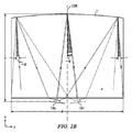
図11は、ファセット面が形成されたミラー端1102を有する楔形導波管1104を有する指向性ディスプレイ装置の構造を側面図で示した概略図である。導波管1104の第1のガイド面1105は全内部反射によって光を案内するように配置されており、第2のガイド面1106はほぼ平坦であり、かつ、第1のガイド面1105から光を出力するために全内部反射を破壊する方向に光を方向付けるように一定の角度で傾斜している。ディスプレイ装置は、第1のガイド面1105に対する法線の方向に光源のアレイ1101からの光を偏向させるために導波管1104の第1のガイド面1105にわたって延在する偏向素子1108を更に有する。更に導波管1104は、入力光を導波管1104を通じて戻るように反射するための反射端1102を更に有してもよく、第2のガイド面1106は、反射端1102からの反射後に光を第1のガイド面1105からの出力光として偏向するように配置されている。反射端は、例えば、図5に示される反射端と同様、横方向(y軸)に正の屈折力を有している。更に、反射端1102のファセット面は反射された光円錐を導波管1104内に偏向して戻り経路上で出力の結合を実現する。したがって、図12Aに示されるのと同様にして視野窓が生成される。更に指向性ディスプレイは、空間光変調器1110及び更に視野窓を与えるように配置された、空間光変調器1110と整列された視差素子1100を有し得る。図12Aに示したものと同様の制御システム72を配置して指向性照明を制御することにより、視差素子及び整列された空間光変調器から視野窓26及び窓109を与えることができる。
FIG. 11 is a schematic diagram showing a side view of the structure of a directional display device having a wedge-shaped
したがって、全内部反射によって光を案内するように第1のガイド面を配置することができ、第2のガイド面はほぼ平面状であり、かつ第1のガイド面から光を出力するために全内部反射を破壊する方向に光を方向付けるように一定の角度で傾斜させることができ、更にディスプレイ装置は、第1のガイド面に対する法線の方向に光を偏向させるために導波管の第1のガイド面にわたって延在する偏向素子を更に含むことができる。 Therefore, the first guide surface can be arranged so as to guide light by total internal reflection, the second guide surface is substantially planar, and all light is output to output light from the first guide surface. The display device can be tilted at a constant angle to direct light in a direction that destroys internal reflections, and the display device further includes a first guide of the waveguide to deflect light in a direction normal to the first guide surface. A deflection element extending over one guide surface may further be included.
図12Aは、ディスプレイ装置100及び制御システムを含む指向性ディスプレイ装置を示した概略図である。以下に制御システムの配置及び作動について説明するが、これらは適宜、変更を施したうえで本明細書に開示されるディスプレイ装置のそれぞれに適用することができる。図12Aに示されるように、指向性ディスプレイ装置100は、段差付き導波管1及び光源照明アレイ15をそれ自体が含み得る指向性バックライト装置を含むことができる。図12Aに示されるように、段差付き導波管1は、光方向付け側面8、反射端4、案内要素10、及び光抽出要素12を有している。指向性ディスプレイ装置100は更にSLM 48を含むことができる。
FIG. 12A is a schematic diagram illustrating a directional display device including the
導波管1は、上記に述べたように配置されている。反射端4は反射光を収束させる。フレネルレンズ62は、反射端4と協働して観測者99によって観測される視野面106に視野窓26が実現できるように配置することができる。SLM 48は、指向性バックライトから光を受光するように配置することができる。更に、導波管1とSLM 48の画素及びフレネルレンズ構造62との間のモアレ干渉縞を実質的に除去するためにディフューザー68を設けてもよい。ディフューザー68は、縦方向(x軸)に横方向(y軸)の拡散よりも大きな拡散を与えるように配置された非対称的ディフューザーとすることができる。有利なことに、ディスプレイの均一度を高め、隣り合う視野窓間のクロストークを最小限に抑えることができる。
The
制御システムは、ディスプレイ装置100に対する観測者99の位置を検出するように配置されたセンサーシステムを含むことができる。センサーシステムは、カメラなどの位置センサー70、及び例えばコンピュータービジョン画像処理システムを含み得る頭部位置測定システム72を含む。制御システムは更に、頭部位置測定システム72から供給される観測者の検出された位置が双方に供給される照明コントローラ74及び画像コントローラ76を含んでもよい。
The control system can include a sensor system arranged to detect the position of the observer 99 relative to the
照明コントローラ74は照明素子15を選択的に作動し、導波管1と協働して光を視野窓26内へと方向付ける。照明コントローラ74は、光が方向付けられた視野窓26が観測者99の左目及び右目に対応した位置に配置されるよう、頭部位置測定システム72によって検出された観測者の位置にしたがって作動される照明素子15を選択する。このようにして、導波管1の横方向の出力指向性は観測者の位置に対応する。
The
画像コントローラ76は、SLM 48を制御して画像を表示する。自動立体ディスプレイを提供するため、画像コントローラ76及び照明コントローラ74は以下のように作動することができる。画像コントローラ76はSLM 48を制御して時間的に多重化された左目画像及び右目画像を表示する。照明コントローラ74は光源15を作動して左目画像及び右目画像の表示と同期して観測者の左目及び右目に対応した位置にあるそれぞれの視野窓に光を方向付ける。このようにして、自動立体視効果を時間的に多重化された技術を使用して実現することができる。更に、又はこれに代えて、以下に述べるような時間的に多重化された技術を用いて低コントラストのプライバシー効果を実現することもできる。
The
図12Bは、空間光変調器48とともに配置された導波管1を有する指向性ディスプレイ装置の構造を斜視図で示した概略図である。反射端4にはフレネルミラーを設けることができる。照明素子15のアレイの光源15a〜15nからの入力結合効率を高め、照明の均一度を高めるためにテーパ領域204を導波管1への入力部に配置することができる。導波管1の縁部の光の散乱領域を隠すために開口部203を有するシェーディング層206を配置することができる。後方リフレクター200は、湾曲し、アレイ15の各光源を窓平面106に結像させることによって与えられる光学窓群から視野窓26を与えるように配置されたファセット面202を有することができる。光学積層体208は、反射型偏光子、リターダー層、及びディフューザーを含むことができる。後方リフレクター200及び光学積層体208については、本明細書に参照によりその全容を援用するところの発明の名称が「Directional backlight」である、2014年2月21日出願の米国特許出願第14/186,862号(代理人整理番号95194936.35500)に更に述べられている。
FIG. 12B is a schematic diagram showing the structure of the directional display device having the
空間光変調器48は、入力偏光子210、TFTガラス基板212、液晶層214、カラーフィルターガラス基板216、及び出力偏光子218からなる液晶ディスプレイを含み得る。赤色画素220、緑色画素222、及び青色画素224を、液晶層214にアレイとして配置することができる。白色、黄色、追加の緑色、又は他の色の画素(図示せず)を液晶層に更に配置することによって透過効率、色域、又は知覚される画像解像度を高めることができる。
Spatial
図12Cは、図4Aに示されるものと同様の配置を有する弁を有する縁部及び側面光源による光学窓の形成を斜視図で示した概略図である。光軸199からオフセットされた光源15nからの光線230は、反射端4で反射されて、窓平面内で軸197から横方向にオフセットされた軸外光学窓26へと方向付けられる。図40に関して示されるのと同様に、側面22の光源17nからの光線232は、側面24における全内部反射によって光学窓26へと方向付けることができる。
FIG. 12C is a schematic perspective view of the formation of an optical window with an edge and side light source having a valve having a similar arrangement as shown in FIG. 4A. The
したがって、指向性ディスプレイ装置100は、入力光を導波管1に沿って案内するための第1のガイド面6及び反対側の第2のガイド面8、並びに導波管1にわたって横方向の異なる入力位置において入力光を発生するように配置された光源15a〜nのアレイ15を有する導波管1を含む指向性バックライトを含む。第1のガイド面6は全内部反射によって光を案内するように配置することができ、第2のガイド面8は、導波管1を通じて案内された光を第1のガイド面8を通って出力光として導波管1の外部に偏向するように配置された複数の光抽出要素12と、導波管1に沿って光を案内するように配置された、光抽出要素12の間の複数の中間領域10とを含み、導波管1は、出力光を、入力光の入力位置に応じて横方向に分配された出力方向において光学窓26内へと方向付けるように配置されている。透過型空間光変調器48は、導波管の第1のガイド面6からの出力光を受光し、これを変調して画像を表示するように配置されている。
Accordingly, the
作動時には、こうしたディスプレイは、光を観測者の近くの視野窓へと方向付け、観測者の目の領域内にない方向に光を浪費しないことにより、高い効率を与えるように配置することができる。更に、こうしたディスプレイは、高い周囲輝度の環境下で視認性を向上させるための高い輝度を与えることができるために望ましい。 In operation, such a display can be arranged to provide high efficiency by directing light to a viewing window near the observer and not wasting light in a direction that is not within the observer's eye area. . Furthermore, such a display is desirable because it can provide high brightness to improve visibility in an environment with high ambient brightness.
空間光変調器は、例えば120Hzのフレームレートを有する時間的に多重化された空間光変調器とすることができ、60Hzのフレームレートの一次画像及び二次画像からなる画像を実現することができる。このような指向性ディスプレイ装置は、上記に述べたような時間的な多重化によって自動立体視ディスプレイを実現することが可能である。 The spatial light modulator can be a temporally multiplexed spatial light modulator having a frame rate of 120 Hz, for example, and can realize an image composed of a primary image and a secondary image of a frame rate of 60 Hz. . Such a directional display device can realize an autostereoscopic display by temporal multiplexing as described above.
第1のガイド面は全内部反射により光を案内するように配置することができ、第2のガイド面は、導波管を通じて案内される光を出力光として第1のガイド面を通って出射することを可能とする方向に方向付けるような向きを有する複数の光抽出要素と、導波管を通じてその光を案内するように配置された光抽出要素間の中間領域とを含むことができる。第2のガイド面は、光抽出要素である複数のファセット面と複数の中間領域とを含む段差付き形状を有する。指向性バックライトは、導波管の複数のファセット面を通り、導波管を通じて戻る方向に透過して第1のガイド面を通って複数の光学窓内へと出射する複数の光源からの光を反射するように配置された複数の反射ファセット面の線形アレイを含む後方リフレクターを更に有することができる。光抽出要素は、横方向に正の屈折力を有することができる。 The first guide surface can be arranged to guide light by total internal reflection, and the second guide surface emits light guided through the waveguide as output light through the first guide surface. A plurality of light extraction elements having an orientation that directs the light in a direction that allows the light to pass through, and an intermediate region between the light extraction elements arranged to guide the light through the waveguide. The second guide surface has a stepped shape including a plurality of facet surfaces that are light extraction elements and a plurality of intermediate regions. The directional backlight transmits light from a plurality of light sources that passes through a plurality of facet surfaces of a waveguide, transmits in a direction returning through the waveguide, and exits into a plurality of optical windows through a first guide surface. Can further include a rear reflector including a linear array of a plurality of reflective facet surfaces arranged to reflect. The light extraction element can have a positive refractive power in the lateral direction.
導波管は入力端を更に有してもよく、入力端に沿って光源のアレイが配置される。導波管は、入力光を導波管を通じて戻るように反射するための反射端を更に有してもよく、第2のガイド面は、反射端からの反射後に光を第1のガイド面からの出力光として偏向するように配置される。反射端は、横方向に正の屈折力を有することができる。 The waveguide may further have an input end, and an array of light sources is disposed along the input end. The waveguide may further include a reflection end for reflecting input light back through the waveguide, and the second guide surface reflects light from the first guide surface after reflection from the reflection end. Are arranged so as to be deflected as output light. The reflection end can have a positive refractive power in the lateral direction.
図13A〜13Cは、軸上光学窓を実現するように配置された光源317aを含む光学弁をそれぞれ正面図、側面図、及び斜視図で示した概略図である。 13A to 13C are schematic views showing an optical valve including a light source 317a arranged so as to realize an on-axis optical window in a front view, a side view, and a perspective view, respectively.
すなわち、本明細書にその全容を参照によって援用するところの発明の名称が「Wide angle imaging directional backlights」である2015年5月27日出願の米国仮特許出願第62/167203号(代理人整理番号384000)に一般的に記載されるように、指向性ディスプレイ装置は、横方向(y軸)に細長い反射端1304を更に有する導波管1301を有してよく、第1及び第2のガイド面6,8が反射端1304の横方向に延びる縁部から延び、導波管1301は第1のガイド面6と第2のガイド面8との間に延びる複数の側面1322,1324を更に有し、更に、光源は側面1322を通過する入力光を与えるために1つの側面1322に沿って配置された光源1317a〜nのアレイ1317を含み、反射端1304は、横方向に互いに交互に配された第1及び第2のファセット面1327,1329を含み、第1のファセット面1327は反射性であり、横方向に正の屈折力を有するフレネルリフレクターの複数の反射ファセット面を形成し、第2のファセット面1329はフレネルリフレクターの複数のドラフトファセット面を形成し、フレネルリフレクター1304は、フレネルリフレクター1304が光源1317のアレイからの入力光を導波管1301内に偏向する方向に側面1322に向かって傾斜した光学軸1287を有する。したがって、角度1277は0°以外の角度である。同様に、第2のファセット面1329は反射性であり、横方向に正の屈折力を有するフレネルリフレクターの複数の反射ファセット面を形成してよく、フレネルリフレクター1304は、フレネルリフレクター1304が光源1319のアレイからの入力光を導波管1301内に偏向する方向に側面1324に向かって傾斜した光学軸1289を有する。
That is, US Provisional Patent Application No. 62/167203 (Attorney Docket Number) filed on May 27, 2015 whose title is “Wide angle imaging directional backlights”, the entire contents of which are incorporated herein by reference. 384000), the directional display device may include a
光源1317aからの例示的な光線1363は光学窓1326aを与えるように配置することができ、光源1317bからの光線1365は光学窓1326bを与えるように配置することができる。例えば、図12Bの配置における導波管1について述べたのと同じ要領で、ディフューザー、プリズム状反射フィルム、リターダー、及び空間光変調器などの他の層を導波管1301と連続して配置することができる。
An
有利なことには、ベゼルサイズの小さい薄いバックライトを実現することができる。かかる配置は、導波管1301の長辺に配置されていない光源を有するためにフォームファクターを小さくすることができる。光源1317及び1319は、光学窓が重なり合うように配置されているためにディスプレイの輝度を高めることができる。
Advantageously, a thin backlight with a small bezel size can be realized. Such an arrangement can reduce the form factor because it has a light source that is not arranged on the long side of the
図14Aは、図9に示されるものと似ているが、1個の2次元的画像が視野円錐249内に与えられ、窓平面106内の各光学窓26の照明によって形成されている、プライバシーモードの指向性ディスプレイの視野窓の配置を平面図で示した概略図である。すなわち、視野窓247は、ディスプレイ100からの各光学窓26の組み合わせから形成されている。視野窓247を有する一次円錐250の外側の円錐233,245内において、窓平面106内の光学窓26の照明は指向性バックライトシステム内の迷光によって与えられる。かかる指向性の光は、例えば、導波管1の入力ファセット面2からの光の散乱、収差、及び反射によって与えることができる。したがって、視野窓245内から観測した場合のディスプレイ100の迷光の輝度は有限であり得、例えば、視野窓247のピーク輝度の1%〜20%である。
FIG. 14A is similar to that shown in FIG. 9, but a single two-dimensional image is provided in the field cone 249 and is formed by the illumination of each
本実施形態では、1つの光学窓は、光源15a〜nのアレイ15の1個の光源によって形成される。1つの視野窓は、複数の光学窓の組み合わせによって形成される。
In the present embodiment, one optical window is formed by one light source of the
すなわち、図12Aに示される制御システム70、72、74、76は、空間光変調器48を制御することが可能であり、光源15a〜nを選択的に作動させて対応する光学窓26内に光を方向付けることが可能であり、指向性バックライト内の迷光は、選択的に作動される光源に対応した光学窓26の外側の円錐233,245によって示される出力方向に方向付けられる。
That is, the
迷光の輝度、すなわちクロストークの制御については、2013年3月15日出願の米国特許出願第13/836,443号、「Crosstalk suppression in a directional backlight」に記載されており、当該出願を本明細書に参照によって援用するものである。 The control of stray light luminance, that is, crosstalk, is described in US Patent Application No. 13 / 83,443, filed March 15, 2013, “Crosstalk suppression in a direct backlight”. Which is incorporated by reference into the book.
図14Aは、図15A〜図15Eを参照して説明する軸外輝度の制御を有するプライバシーディスプレイの作動を示す。 FIG. 14A illustrates the operation of a privacy display with off-axis brightness control described with reference to FIGS. 15A-15E.
更に図14Aは、図16A〜図16Eを参照して説明する軸外輝度及びコントラスト制御を有する第1の動作位相におけるプライバシーディスプレイの作動を示す。 Further, FIG. 14A shows the operation of the privacy display in a first operating phase with off-axis brightness and contrast control as described with reference to FIGS. 16A-16E.
図14Bは、本実施形態のプライバシーモードの第2の動作位相における指向性ディスプレイの光学窓の配置を平面図で示した概略図である。第2の動作位相では、ディスプレイ上の1個の点に対する二次視野円錐252,254とともに示される二次視野窓241,243が視野窓247の両側に与えられる。図14Cは、本実施形態のプライバシーモードの第1及び第2の動作位相における指向性ディスプレイの光学窓の配置を平面図で示した概略図である。視野円錐250と252,254との間には移行円錐256,258が与えられ、ここからディスプレイ輝度は一次円錐と二次円錐との間で変化するように見える。
FIG. 14B is a schematic diagram illustrating the arrangement of the optical windows of the directional display in the second operation phase of the privacy mode of the present embodiment in a plan view. In the second operating phase,
本実施形態では、典型的には、一次観測者を一次円錐250内に配置し、二次観測者を二次円錐254内に配置することができる。一次観測者の位置は、複数の光学窓26によって与えられる一次視野窓であり得る一次光学窓内に位置し得る。二次観測者は一次光学窓の外側に位置してよく、複数の光学窓26によって与えられる二次視野窓であり得る二次光学窓内に位置し得る。本実施形態の目的では、一次光学窓(複数の光学窓からなる一次視野窓であり得る)は、強度がピーク輝度の50%未満にまで低下する輝度分布の幅として定義することができる。典型的には、迷光は、反射される光の入力側面2にわたるほぼ均一な分布のため、比較的均一な輝度分布を与えることができる。
In the present embodiment, typically, the primary observer can be placed in the
有利なことには、図14A〜図14Cの配置、並びに広角モード、高効率モード、高輝度モード、及び自動立体視モードは、光源のアレイ15の制御手段によって切り換えることができる。
Advantageously, the arrangement of FIGS. 14A-14C and the wide angle mode, high efficiency mode, high brightness mode, and autostereoscopic mode can be switched by the control means of the
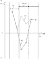
図15A〜図15Eは、少なくとも1つの動作位相において一次画像が空間光変調器上に与えられる、プライバシーモードにある指向性ディスプレイの作動を示す概略図である。かかる配置は、例えば、低輝度プライバシーディスプレイ用では図14Aに示されるような、又は本明細書に述べられる不明瞭化された画像プライバシーディスプレイ用では図14Bに示されるような視野窓の配置と協働させて使用することができる。図15Aは、窓平面内で一次照明構造を実現するための位置260に対する光源のアレイ15内の光源15a〜nの相対光束262を示している。したがって、これは複数の一次光源がある場合の一例である。すなわち、個別の光源の光束264はアレイの中央付近の領域では均一であり、他の領域では0であり得る。あるいは、光束264は、一次視野円錐250内で視野角とともに段階的に変化する輝度を与えるために照明される素子にわたって変化させてもよい。
15A-15E are schematic diagrams illustrating the operation of a directional display in privacy mode in which a primary image is provided on the spatial light modulator in at least one operating phase. Such an arrangement, for example, cooperates with the viewing window arrangement as shown in FIG. 14A for a low brightness privacy display or as shown in FIG. 14B for the obscured image privacy display described herein. Can be used by working. FIG. 15A shows the relative
図15Bは、例えば透過率0%の低透過率領域268及び例えば透過率100%の高透過率領域266を有する空間光変調器48上に表示された例示的な一次画像261を示す。図15Cは、ディスプレイ100の視野角270に対する相対輝度及びコントラストの変化を示すグラフを示す。すなわち、輝度分布272は、中央視野窓247と、輝度が0ではない、例えば以下の実例において角度位置251において10%である迷光領域241とを含んでいる。図に示されるように、作動時には迷光の量は領域241内で異なり得る。しかしながら、迷光は主として導波管1の入力側面2からの戻り反射によって決まるため、これらの領域では比較的均一な出力が実現できる。一次視野窓は縁部幅256を有し得る。
FIG. 15B shows an exemplary
図15Cは、視野角に対する空間光変調器48上に見られる知覚画像のコントラストの分布274を更に示す。下記図27〜28で更に述べるように、このようなコントラストは軸上ではほぼ均一であり得るが軸外の位置では低下し得る。
FIG. 15C further shows the
図15Dは、一次視野窓247内の一次観測者に知覚される一次画像280を示したものであり、領域267,269はそれぞれ領域266,268の相対透過率にほぼ等しい100%,0%の相対輝度を有している。図15Eは、領域271,273を含む、角度位置251において知覚される二次画像282を斜視図使って表したものである。この実例では領域273がほぼ0%の輝度を有し得るのに対して、領域271は10%の輝度を有し得るが、これは領域266の透過率が角度位置251における迷光の輝度によって変調されたものである。
FIG. 15D shows the
したがって、図15A〜15Eの配置は、二次観測者に対する輝度が一次観測者に対する輝度の10%であるようなプライバシーモードで作動させることができる。このような画像輝度によって、二次観測者に対して一次画像を不明瞭化することができる。詳細には、不明瞭化は、(i)正面反射、及び(ii)目が周囲の照明レベルに慣れることでディスプレイが暗く見えるようになること、によって与えることができる。二次観測者に対する一次画像のコントラストはほぼ同じであり得るため、各要素は依然視認される。 Accordingly, the arrangement of FIGS. 15A-15E can be operated in a privacy mode where the luminance for the secondary observer is 10% of the luminance for the primary observer. Such image brightness can obscure the primary image to the secondary observer. Specifically, obscuration can be provided by (i) frontal reflections, and (ii) the display becomes darker as the eye gets used to the ambient lighting level. Each element is still visible because the contrast of the primary image to the secondary observer can be approximately the same.
後述するように、二次観測者に対する一次画像を更に不明瞭にすることが望ましい場合もある。本実施形態では、図15A〜15Eの配置は、時間的に多重化ディスプレイの第1の動作位相において与えることができる。第2の動作位相を与えることで更なる画像の不明瞭化が実現される。 As will be described later, it may be desirable to further obscure the primary image for the secondary observer. In this embodiment, the arrangement of FIGS. 15A-15E can be given in time in the first operating phase of the multiplexed display. By providing the second operating phase, further image obscuration is achieved.
図16A〜16Eは、第1の位相において一次画像が空間光変調器上に与えられ、第2の動作位相において二次画像が空間光変調器上に与えられる、プライバシーモードにある指向性ディスプレイの第2の位相における作動を示す概略図である。これは複数の二次光源がある場合の一例である。図16Aは、二次光源が異なる光束の光を出力するようにアレイ15の光源が作動される様子を示している。その結果、光束262による二次照明構造が実現されることにより、光源の光束265が迷光領域241内の一次照明からの迷光とほぼ同じ輝度を与えるように配置される。図16Cに示されるように、輝度構造294は迷光領域241内の構造272とほぼ一致させることができ、したがって例示的な実施形態では、角度位置251において10%の輝度を実現することができる。二次位相における角度コントラスト分布274は一次位相におけるものと同じである。図16Bは、領域290における透過率が0%であり、領域292における透過率が100%である一次画像263を示している。したがって、表示される二次画像263は、表示される一次画像261と比較して反転したものとなり得る。
16A-16E show a directional display in privacy mode in which a primary image is provided on the spatial light modulator in a first phase and a secondary image is provided on the spatial light modulator in a second operating phase. It is the schematic which shows the action | operation in a 2nd phase. This is an example when there are a plurality of secondary light sources. FIG. 16A shows how the light sources of the
図16Dは、輝度0%の領域284と輝度1%の領域286とを有する一次観測者300に対して知覚される一次画像281を示している。領域286の軸上輝度295は、一次視野窓247内に含まれる二次照明パターン(光束265の分布により決定される)からの迷光によって決定され、この実例では、典型的には、透過率10%の10%、すなわち1%である。したがって、一次画像の知覚されるコントラストは、第2の位相では例えば100:1以下にわずかに劣化し得る。迷光輝度295を低下させると知覚される一次画像コントラストが増大し得る。
FIG. 16D shows a
図16Eは、領域292におけるSLM 48の透過率及び位置251における輝度により決定される、輝度0%の領域288と輝度10%の領域290とを含む知覚される二次画像283を斜視図で表したものである。
FIG. 16E is a perspective view of a perceived
第2の位相で知覚される画像283は、第1の位相で知覚される画像282のほぼ逆であることが観察されよう。後述するように、複数の画像が合成されて極めてコントラストが低い知覚される二次画像が実現される。有利なことには、コントラストの低下によって二次視野窓241内の二次観測者に対する一次画像の高い不明瞭化度を与えることができる。
It will be observed that the
図16Fは、一次画像のグレーレベルと二次画像のグレーレベルとの間の関係を示した概略的なグラフである。一次画像の反転コピーは、反転関数によって反転された一次画像のコピーからなるものとすることができる。したがって、一次画像のグレーレベル371及び二次画像のグレーレベル373のグラフは、反転関数373によって示されるように線形となり得る。反転関数375は、二次光源の光束の制御によって補償することが可能な低いグレーレベルを有する線形であり得る。更に、反転関数は関数377,379のように非線形のものであってもよい。有利なことには、グレースケールマッピングを、観測者の視野の積分区間にわたって合成された一次画像と二次画像の視認性を最小化するように調節することができる。
FIG. 16F is a schematic graph showing the relationship between the gray level of the primary image and the gray level of the secondary image. The inverted copy of the primary image may consist of a copy of the primary image that has been inverted by an inversion function. Thus, the graph of the
図17は、空間光変調器及び光源アレイに対する画像及び照明の提示の流れを示した概略図である。図17は、一次及び二次光源264,265の照明と同期した第1及び第2の位相における一次及び二次表示画像の提示の流れを示している。二次画像263は、一次観測者300によって知覚される際、一次光学窓247の外側に方向付けられる迷光241を変調する一次画像261を少なくとも部分的に打ち消すように配置された一次画像261の反転コピーからなるものとすることができる。
FIG. 17 is a schematic diagram showing a flow of presentation of images and illumination for the spatial light modulator and the light source array. FIG. 17 shows the flow of presentation of the primary and secondary display images in the first and second phases synchronized with the illumination of the primary and secondary
制御システムは、空間光変調器48及び光源のアレイ15a〜nを互いに同期して制御するように配置され、これにより、(a)一次観測者300に見えるように、少なくとも1つの一次光源264が少なくとも1つの光学窓247内に光を方向付けるように選択的に作動される間に空間光変調器48が一次画像261を表示し、(b)少なくとも1つの一次光源264以外の少なくとも1つの光源265が少なくとも1つの一次光学窓247の外側の複数の二次光学窓241内に光を方向付けるように選択的に作動される間に、一次画像261の表示と時間的に多重化された方式で、空間光変調器48が二次画像263を表示する。
The control system is arranged to control the spatial
有利なことには、二次画像のコントラストを低下させることにより不明瞭化を実現することができる。 Advantageously, obscuring can be achieved by reducing the contrast of the secondary image.
図18A〜18Cは、それぞれの一次及び二次画像を含み、更に一次観測者に対する二次画像からのクロストークを含む、第1及び第2の位相によってプライバシーディスプレイで知覚される画像の見え方の正面図を遠近法で表した概略図である。 FIGS. 18A-18C include the primary and secondary images, respectively, and further the appearance of the image perceived on the privacy display by the first and second phases, including crosstalk from the secondary image to the primary observer. It is the schematic which represented the front view by the perspective method.
図18Aは、第1の動作位相を示している。一次観測者300は、視野窓247によって示される少なくとも1つの一次光学窓内の観測位置から一次画像280を知覚する。視野窓241内の二次観測者302には、一次画像280と同じコントラスト分布を有し、一次照明光束264の分布の迷光によって与えられる輝度を有する画像282が見える。
FIG. 18A shows the first operating phase.
図18Bは、第2の動作位相を示している。二次観測者302は、視野窓241によって示される少なくとも1つの二次光学窓内の観測位置から二次画像283を知覚する。一次視野窓247内の一次観測者300には、二次画像283と同じコントラスト分布を有し、二次照明光束265の分布の迷光によって与えられる輝度を有する画像281が見える。
FIG. 18B shows the second operation phase. The
図18Cは、一次観測者300に見える合成された知覚画像285及び二次観測者302に見える合成された知覚画像287を示している。したがって、一次光学窓の外側の二次観測者302によって知覚される二次画像287は、一次光学窓の外側に方向付けられた迷光を変調する一次画像280を不明瞭化する。
FIG. 18C shows a synthesized
特に断わらないかぎり、指向性ディスプレイ装置の一次光学窓の外側に方向付けられた迷光を変調する、一次画像を不明瞭化する方法であって、向性ディスプレイ装置が、指向性バックライト内の迷光が、選択的に作動される光源に対応する複数の光学窓の外側の複数の出力方向に向けられる指向性バックライトと、導波管の第1のガイド面からの出力光を受光し、これを変調して画像を表示するように配置された透過型空間光変調器とを有する、方法が提供され得る。本方法は、空間光変調器と光源のアレイとを互いに同期させて制御することを含み得ることにより、(a)一次観測者に見えるように、少なくとも1つの一次光源が少なくとも1つの一次光学窓内に光を方向付けるように選択的に作動される間に空間光変調器が一次画像を表示し、(b)少なくとも1つの一次光源以外の光源が少なくとも1つの一次光学窓の外側の複数の二次光学窓内に光を方向付けるように選択的に作動される間に、一次画像の表示と時間的に多重化された方式で、空間光変調器が二次画像を表示し、一次光学窓の外側の二次観測者によって知覚される二次画像が、一次光学窓の外側に方向付けられた迷光を変調する一次画像を不明瞭化する。 Unless otherwise specified, a method of obscuring a primary image that modulates stray light directed outside a primary optical window of a directional display device, wherein the directional display device is a stray light in a directional backlight. Receiving directional backlights directed in a plurality of output directions outside a plurality of optical windows corresponding to selectively activated light sources and output light from the first guide surface of the waveguide, And a transmissive spatial light modulator arranged to modulate the image and display an image. The method may include controlling the spatial light modulator and the array of light sources in synchronization with each other so that (a) at least one primary light source is visible to the primary observer so that at least one primary optical window is visible. The spatial light modulator displays a primary image while being selectively activated to direct light in, and (b) a light source other than the at least one primary light source has a plurality of light sources outside the at least one primary optical window. While selectively activated to direct light into the secondary optical window, the spatial light modulator displays the secondary image in a time multiplexed manner with the display of the primary image, and the primary optics. A secondary image perceived by a secondary observer outside the window obscures the primary image that modulates stray light directed outside the primary optical window.
図19Aは、図18A〜18Cの配置についてディスプレイの輝度及びコントラストのグラフを示した概略図である。すなわち、角度輝度分布272を第1の動作位相で与え、角度輝度分布294を第2の動作位相で与えることができる。一次観測者300に知覚される一次画像285のコントラストは、角度コントラスト分布274を有する単一位相動作型ディスプレイと比較した場合にわずかに軸上寄りのコントラストを有する角度分布296を有し得る。一次光学窓247の外側の二次知覚画像287の観測者に見えるコントラストは、輝度及びコントラストが大幅に低下している。有利なことには、一次画像は、図15E及び18Aの知覚画像282と比較して二次画像に大きく不明瞭化される。
FIG. 19A is a schematic diagram showing display brightness and contrast graphs for the arrangements of FIGS. That is, the
一次画像は上記に述べたような2次元画像であり得る。3次元画像についてプライバシー作動モードが与えられることが望ましい場合がある。 The primary image can be a two-dimensional image as described above. It may be desirable to provide a privacy mode of operation for a 3D image.
図19Bは、自動立体視プライバシーディスプレイ用のディスプレイ輝度及びクロストークのグラフを示した概略図であり、図19Cは、自動立体視プライバシーディスプレイ用の空間光変調器及び光源アレイに対する画像及び照明の提示の流れを示した概略図である。 FIG. 19B is a schematic diagram showing a display luminance and crosstalk graph for an autostereoscopic privacy display, and FIG. 19C presents images and illumination for a spatial light modulator and light source array for an autostereoscopic privacy display. It is the schematic which showed the flow.
代表的な一実施形態では、第1の動作位相において、左目の一次画像を角度輝度分布297を有する左目の一次光学窓と同期して与えることができる。第2の動作位相において、右目の一次画像を角度輝度分布298を有する右目の一次光学窓と同期することができる。
In an exemplary embodiment, the primary image of the left eye can be provided in synchronization with the primary optical window of the left eye having an
第3の動作位相において、二次画像を、少なくとも1つの一次光学窓の外側の、分布294によって示される少なくとも1つの光学窓と同期して与えることができる。二次画像は2次元画像であり得る。二次画像の透過率は、aを定数とし、Lを左画素透過率、及びRを右画素透過率として、1−a(L+R)により画素ごとに配置することができ、得られる一次自動立体視画像を一次左及び右光学窓の外側の二次観測者302に対して不明瞭化するように配置することができる。
In the third operating phase, the secondary image can be provided in synchronization with at least one optical window, indicated by
したがって、一次画像は左目画像及び右目画像を含む3次元画像となり得る。制御システム70、72、74、76は、(a1)空間光変調器48を制御して左目画像及び右目画像を時間的に多重化された方式で表示し、かつ(a2)空間光変調器48が左目画像及び右目画像をそれぞれ表示する際、光源15a〜nのアレイ15を空間光変調器48の制御と同期して制御することで異なる一次光源264を選択的に作動させて一次観測者300の左目及び右目に見えるように少なくとも1つの一次光学窓内に光を方向付けることにより、空間光変調器48を制御して一次画像を表示するように配置することができる。
Therefore, the primary image can be a three-dimensional image including a left eye image and a right eye image. The
有利なことには、一次観測者に対しては自動立体視3D作動を、一次光学窓297,298の外側の二次観測者に対しては3D画像の不明瞭化を実現することが可能な自動立体視ディスプレイを提供することができる。更に、左目及び右目の画像を実質的に単一の位相で不明瞭化することができるため、3つの動作位相を用いてプライバシー機能を実現することができる。 Advantageously, autostereoscopic 3D operation can be achieved for primary observers, and 3D images can be obscured for secondary observers outside the primary optical windows 297,298. An autostereoscopic display can be provided. Furthermore, since the left-eye and right-eye images can be obscured with a substantially single phase, the privacy function can be realized using three operating phases.
一次観測者の視野の自由の制御を与えることが望ましい場合がある。 It may be desirable to give control of the primary observer's field of view.
図20A〜20B、21、22は、第1及び第2の位相について角度輝度分布のグラフを示した概略図である。 20A to 20B, 21 and 22 are schematic views showing graphs of angular luminance distributions with respect to the first and second phases.
指向性ディスプレイ装置は、一次観測者300の頭部の位置を検出するように配置されたセンサーシステム70を更に含んでもよく、制御システムは観測者300の頭部の検出された位置にしたがって光源15a〜nを制御するように配置される。図20Aに示されるように、一次光学窓312は、一次光学窓312の外側の二次観測者302に対する不明瞭化された画像とともに一次画像を維持するため、角度311だけシフトした調節された角度分布を有することができる。有利なことには、横方向に観測者の自由度を高めることができる。
The directional display device may further include a
図20Bは、一次光学窓316の幅313が変化する幅を有し得ることを示している。この変化は、手動制御によって、又は受動的照明システムにおけるように広視野自由度が求められないヘッドトラッキングの使用によって実現することができる。有利なことには、システム内の迷光の量を低減し、二次画像の不明瞭性を高めることができる。更に、二次観測者が不明瞭化されない一次画像を見ることができる領域が狭められる。
FIG. 20B shows that the
図21は、一次光学窓310のプロファイル313を変化させることができることを示している。例えば、輝度分布322を有する二次光学窓をディスプレイの一方の側にのみ与えることができる。有利なことには、二次観測者を不明瞭化された画像と共に一方の側に配置することができる一方で、二次観測者302の反対側の第3の観測者は不明瞭化されていない画像を見ることができる。したがって、一次観測者は二次観測者302からのプライバシーを維持しながら第3の観測者とディスプレイを共有することができる。
FIG. 21 shows that the
図22は、二次光学窓310のプロファイル326に、位置251において分布324によって示される一次光学窓からの迷光の輝度と比較してより高い輝度を与えることができることを示している。二次画像263には、不明瞭化効果を高めるために更なる透過率低下を適用することができ、これにより得られる輝度が一致する。有利なことには、画像透過率の制御を、光源の光束265の制御よりもより便宜よく調整することができるため、二次知覚画像のコントラストを更に微調整することによって二次観測者302に対する一次画像のより高い不明瞭化を実現することができる。
FIG. 22 shows that the
ディスプレイを観察している二次観測者302がいない場合には一次観測者300に知覚される一次画像のコントラストを高めることが望ましい場合がある。周知の顔検出装置及び追跡装置を二次観測者の存在の有無を検出するように配置することができる。
It may be desirable to increase the contrast of the primary image perceived by the
図23A〜23Bは、それぞれ二次観測者の非検出及び検出について第2の位相にあるプライバシーディスプレイにおいて知覚される画像の見え方の正面斜視図を示した概略図である。センサーシステム70は、一次光学窓247の外側の二次観測者302を検出するように配置することができ、制御システム72、74、76は、二次観測者302が検出されたことに応じて空間光変調器48が一次画像261及び二次画像263を時間的に多重化された方式で表示するように空間光変調器48及び光源15a〜nのアレイの制御を互いに同期して行い、また、二次観測者302が検出されていないことに応じて、少なくとも1つの一次光源が、一次観測者300に見えるように少なくとも1つの一次光学窓247内に光を方向付けるように選択的に作動される間に空間光変調器が、二次画像263を時間的に多重化された方式で表示することなく一次画像261を表示するように空間光変調器48及び光源のアレイを制御するように配置することができる。有利なことには、一次観測者により高いコントラストの画像を与えることができる。更に、光源15a〜nを時間的に多重化のパルス電流駆動スキームに対して連続的な駆動電流によって駆動することによってディスプレイの輝度を高めることができるようにディスプレイを時間的に多重化する必要がない場合もある。
FIGS. 23A-23B are schematic diagrams showing front perspective views of how an image is perceived on the privacy display in the second phase for non-detection and detection of the secondary observer, respectively. The
図24〜25は、時間に対する画素透過率レベルの変化、時間に対するアドレス指定信号レベルの変化、及び時間に対する輝度の積分値レベルの変化の第1及び第2のアドレス指定スキームのグラフをそれぞれ示した概略図である。図24は、1個の画素について、所望の透過率が、358の位相周期で、第1の位相で作動する画素では334、338、342として、第2の位相で作動する場合の画素では336、340、344として変化し得ることを示している。画素駆動信号は、所望のグレースケール変化に一致させた関数352によって与えることが考えられる。液晶ディスプレイなどの空間光変調器48の時間的なグレースケール応答特性は、典型的には、所望の非変動関数354ではなく、結果として得られる積分された画素透過率関数356である。図25は、画素駆動関数360を望ましくは適用することによって位相周期358にわたって積分して得られる画素透過率において線形関数354,360を実現することができることを示している。有利なことには、二次画像を、空間光変調器48を高速で切り換えるための一次画像の適正な反転を与えるように駆動することができる。
FIGS. 24-25 show graphs of the first and second addressing schemes, respectively, of the change in pixel transmittance level over time, the change in addressing signal level over time, and the change in luminance integral level over time. FIG. FIG. 24 shows that for one pixel, the desired transmittance is 334, 338, 342 for pixels operating in the first phase and 336 for pixels operating in the second phase with a phase period of 358. 340, 344 can be changed. It is conceivable that the pixel drive signal is provided by a
図26A〜26Bは、時間に対するアドレス指定信号の変化の第1及び第2のアドレス指定スキームのグラフをそれぞれ示した概略図である。パネルアドレス指定を行うための適正な電気的反転スキームを提供することが望ましい場合がある。液晶セル内部における電荷移動による画像のスティッキングを防止するため、典型的には、液晶ディスプレイでは正電圧と負電圧の交互に変化する電界を用いている。図26Aに示されるように、かかるスキームを関数360に適用した場合にはアドレス指定スキーム361が与えられ、複数の周期358にわたって画素上に不均一な電荷分布を供給することができる。かかるスキームは本実施形態の反転画像の性質によって特に強調され、画像のスティッキングにつながり得る。好ましくは、隣り合う位相周期にわたって反転が完了される図26Bの配置が提供される。この場合、全出力は常に一定であり、高性能の反転補正を配置することができる。有利なことには、画像スティッキングを最小限に抑えることができる。
FIGS. 26A-26B are schematic diagrams illustrating graphs of first and second addressing schemes, respectively, of changes in addressing signals over time. It may be desirable to provide a proper electrical inversion scheme for performing panel addressing. In order to prevent image sticking due to charge transfer inside the liquid crystal cell, the liquid crystal display typically uses an electric field that alternates between a positive voltage and a negative voltage. As shown in FIG. 26A, when such a scheme is applied to function 360, an addressing
図27〜28は、それぞれ捩れネマティック液晶ディスプレイ及び補償された捩れネマティック液晶ディスプレイの極座標系の等コントラストプロットを示した概略図である。一次観測者300には中心領域452に一次画像261及び迷光で照らされた二次画像362が観察されるのに対して、二次観測者には極座標で縁部領域456、457、458に二次画像263が観察される。図27に示されるような補償されていない捩れネマティック(TN)ディスプレイでは、各領域は異なるグレースケール性能を有し得るものであり、したがって、例えば領域456における反転した二次画像の知覚される見え方は領域457における反転した二次画像の知覚される見え方とは異なる。したがって、二次観測者に対する一次画像の不明瞭化は視野角によって不必要に異なり得る。図28は、補償されたTNが、軸外の二次観測者について同様のグレースケール性能を与えることができ、したがって、知覚される二次画像287のコントラスト低減による不明瞭化がより広い観測者の位置の範囲にわたって有利にも実現され得る。
FIGS. 27-28 are schematic diagrams showing isocontrast plots of polar coordinate systems of a twisted nematic liquid crystal display and a compensated twisted nematic liquid crystal display, respectively. The
反転された二次画像263の精度を高めることによって不明瞭化のレベルを更に向上させることが望ましい場合がある。
It may be desirable to further improve the level of obscuration by increasing the accuracy of the inverted
図29は、二次観測者の測定された極座標位置に基づく二次画像グレースケールの補正を示したフローチャートである。第1のステップ401では、二次観測者の目の平均的な位置を二次画像によって定められる面積にわたって測定する。第2のステップ402では、その極角に対する空間光変調器48のグレースケール特性を、例えば、参照テーブルによって評価する。第3のステップ403では、適正に反転された画像を得るために適用するのに適当な信号を計算する。第4のステップ404では、二次画像を一次画像の表示と同期して表示する。
FIG. 29 is a flowchart showing correction of the secondary image gray scale based on the polar coordinate position measured by the secondary observer. In a
図30は、時間的に多重化されたディスプレイで作動している空間光変調器の出力透過率に対する第1の画像の入力グレースケール420と第2の入力グレースケール422のグラフを示した概略図である。すなわち、1個の画素の出力透過率が非線形的な形で変化することが分かる。このようなグラフは、ステップ402又は反転画像の適正な画素設定を評価するための他のステップにおいて使用することができる参照テーブルの基準として用いることができる。したがって、空間光変調器48は画素のアレイを含み、制御システム72,76は、画素の所望のグレーレベル及び画素の予想されるヒステリシスを考慮して空間光変調器48を制御することにより、一次及び二次画像261,263の時間的に多重化された表示の間に各画素の駆動レベルを制御するように配置することができる。
FIG. 30 is a schematic diagram illustrating a graph of a first
図31は、交互に変化する一次及び二次画像の画素データの適正なアドレス指定を実現するための信号データの処理を示したフローチャートである。制御システム72、74、76は、二次画像263が一次光学窓247の外側に方向付けられる迷光を変調する一次画像261と同じ輝度を有するように、空間光変調器48及び光源15a〜nのアレイを制御するように配置することができる。
FIG. 31 is a flowchart showing signal data processing for realizing proper addressing of pixel data of primary and secondary images that change alternately. The
例示的な一実施形態では、第1のステップ412において、一次画像のグレーレベルを入力する。第2のステップ414では、一次画像の画素駆動レベルを計算し、第3のステップ416に示されるように第1の位相において一次画像のそれぞれの画素を駆動するために使用する。第4のステップ406では、所望の反転されたグレースケールレベルを計算し、第5のステップ408では、図30に示されるような入力グレーレベルのデータ及びマッピング機能を更に用いて適当な反転駆動レベルを計算する。第6のステップ410では、二次画像の画素データを第2の位相と同期させて駆動する。
In an exemplary embodiment, the
有利なことには、一次画像の不明瞭化を、知覚される二次画像287の低減されたコントラストを与えることによって強化することができる。
Advantageously, obfuscation of the primary image can be enhanced by providing a reduced contrast of the perceived
作動時には、例えばディスプレイの面積によって定められる有限な円錐角のために、知覚される二次画像287の残留画像コントラストを完全に除去すること、又は様々な二次観測者の位置を補償することは常に可能というわけではない。二次観測者に対する一次画像の更なる不明瞭化を与えることが望ましい場合もある。
In operation, it is not possible to completely remove the perceived residual image contrast of the
図32A〜32Cは、それぞれの一次及び二次画像を含み、更に妨害パターン画像コンテンツを含む、第1及び第2の位相によってプライバシーディスプレイで知覚される画像の見え方の正面図を遠近法で表した概略図である。図32Aは、例えば、図18Aに示されるものとほぼ同じであってもよい。図32Bは、第2の画像283に妨害パターン420を付加することができることを示している。かかる二次パターンは固定されたものでも又は時間的に変化するものでもよい。妨害パターンは、提示される画像の性質を最も効果的に妨害するものを選択することができ、例えば、一次画像の空間周波数ピークと似た空間周波数を有するが異なる構造のものとすることができる。したがって、妨害パターン420は、テキスト及び写真間で異なるものでよく、空間光変調器48の面積にわたって性質が更に変化してもよい。二次観測者302に見える知覚される二次画像287は、低コントラストの一次画像に加えて低い妨害パターンを示すことができる。
32A-32C are perspective front views of the image perceived on the privacy display by the first and second phases, including the respective primary and secondary images, and further including the disturbing pattern image content. FIG. FIG. 32A may be substantially the same as that shown in FIG. 18A, for example. FIG. 32B shows that an
有利なことには、二次観測者302に対する一次画像の不明瞭化を向上させることができる。
Advantageously, obscuration of the primary image for the
知覚される一次画像285の妨害パターンの視認性は最小限に抑えることが望ましい場合がある。
It may be desirable to minimize the visibility of the perturbation pattern of the perceived
図33は、妨害パターン画像コンテンツを含む時間的に多重化された一次及び二次画像の画素データの適正なアドレス指定を実現するための信号データの処理を示したフローチャートである。二次画像263は、妨害パターン420が重ね合わされた一次画像の反転コピーを含むことができる。二次画像263は、妨害パターン420を含むことができる。一次画像261は、一次観測者300によって知覚される際、二次光学窓241の外側に方向付けられる迷光を変調する妨害パターン420を少なくとも部分的に打ち消すように配置された妨害パターン420の反転コピーが重ね合わされた一次観測者に対して表示するための画像を含むことができる。図33は、図31と似ているが、二次画像263に妨害パターンを付加する更なるステップ422、及び一次画像から妨害パターンを少なくとも部分的に差し引くために追加されたステップ424を含んでいる。有利なことには、一次画像の妨害パターンの見え方を最小限に抑えることができる。
FIG. 33 is a flow chart illustrating the processing of signal data to implement proper addressing of temporally multiplexed primary and secondary image pixel data including disturbing pattern image content. The
光源15a〜nの時間的な照明パターンのタイミングを空間光変調器48のアドレス指定と同期させることによってディスプレイの輝度を最適化するとともに一次画像と二次画像との間のクロストークを最小限に抑え、これにより二次観測者に対する向上した画像の不明瞭化を実現することが望ましい場合がある。
Synchronizing the timing of the temporal illumination patterns of the
図34A〜34Bは、位相の長さが一致した一次及び二次画像のアドレス指定並びにそれぞれの照明信号を示した概略タイミング図である。一次位相480のアドレス指定信号470及び二次位相482のアドレス指定信号472が逆位相で示されている。空間光変調器48のアドレス指定は信号474に示され、画素列指定が周期484に、液晶応答時間が周期486に、照明スロットが488に示されている。一次照明タイミング信号476は、例えば図15Aに光源の光束264により示されるような第1の位相において高輝度とするためのパルス幅が変調された出力を与えるパルス492によって示される。二次照明タイミング信号478は、例えば図16Aに光源の光束265により示されるような第2の位相においてより低い輝度とするためのパルス幅が変調された出力を与えるパルス492によって示される。図34Bに示されるように、フリッカを有利に低減させ、パネル面積にわたって画像の不明瞭化の高い均一性を与えることができる、より幅広く分配されたパルス496を第2の位相において与えることが望ましい場合がある。
FIGS. 34A-34B are schematic timing diagrams illustrating the addressing of primary and secondary images with matching phase lengths and respective illumination signals. The
図34A〜34Bの配置は、最大のディスプレイ輝度が照明スロット488の幅によって制限され得ることを示している。照明スロット幅を大きくすることによってディスプレイ輝度を高めることが望ましい場合がある。 The arrangement of FIGS. 34A-34B shows that maximum display brightness can be limited by the width of the illumination slot 488. It may be desirable to increase display brightness by increasing the illumination slot width.
図34Cは、位相の長さが一致していない一次及び二次画像のアドレス指定並びにそれぞれの照明信号を示した概略タイミング図である。制御システム72、74、76は、空間光変調器48が不均等な長さの時間スロット480,482で時間的に多重化された方式で一次画像261及び二次画像263を表示するように空間光変調器48及び光源15a〜nのアレイを互いに同期させて制御するように配置することができる。パネルアドレス指定の周期484及び液晶応答の周期486は、スロット480,482の両方において同じであってよく、したがって照明スロット487をスロット489よりも長くすることができる。これにより、図34Bのパルス490と比較して延長されたパルス496が与えられる。第2の位相の照明スロット幅489は、図16Aに示される第2の光束265に適当な強度を与えるだけ充分に長く設定される。有利なことには、ディスプレイ輝度を高めることができる。
FIG. 34C is a schematic timing diagram illustrating primary and secondary image addressing and the respective illumination signals that do not match in phase length. The
時間とともに変化し得る妨害パターンを二次画像に与えるための更なる配置が提供されることが望ましい。このような時間とともに変化するパターンは、図32Cの妨害二次画像パターンを更新することによって実現することができる。一次画像の残留妨害パターンの視認性を制限するために二次画像を改変することなく妨害パターンを実現することが更に望ましい。 It would be desirable to provide further arrangements to give the secondary image a disturbance pattern that can change over time. Such a pattern changing with time can be realized by updating the interference secondary image pattern of FIG. 32C. It is further desirable to implement the interference pattern without modifying the secondary image to limit the visibility of the residual interference pattern of the primary image.
図35A〜35Bは、少ない数の光源による照明のための光弁にわたって空間輝度の変化を示す概略図であり、したがって軸外観測位置に対する一次画像700の照明を表している。ボイドA(530)及びボイドB(532)が示されているが、本明細書の別の箇所で説明する。照明領域704,702は、窓平面の近くであるが必ずしも窓平面になくともよい1対の別々の光源によって与えられる。かかる不均一な照明領域は、光学系の収差、特に反射端4及び湾曲ファセット面14のフレネルミラーによって与えられ、観測位置及び光学設計に応じて形状及び位置が変化し得る。光源の第2の対に対して領域706,708が更に与えられる。本明細書の別の箇所で述べるように、領域702と領域704との間の領域705には、より輝度の低い迷光が例えば入力側面2からの反射によって与えられ得る。
FIGS. 35A-35B are schematic diagrams showing the change in spatial luminance across the light valve for illumination with a small number of light sources, and thus represent illumination of the
図35Cは、多い数の光源による照明のための光弁にわたって合成された空間輝度を示した概略図である。作動時には、典型的には、複数の隣り合う光源が、光をディスプレイ表面の全体に拡散して軸外の観測位置に対して均一な照明を与えるディフューザー素子とともに設けられる。 FIG. 35C is a schematic diagram showing the combined spatial luminance across the light valves for illumination with a large number of light sources. In operation, a plurality of adjacent light sources are typically provided with a diffuser element that diffuses light across the display surface to provide uniform illumination for off-axis observation positions.
後述するように、更なるプライバシー作動モードでは、かかる不均一性を利用して二次観測者に対して更なる妨害画像を与えることができる。 As will be described later, in the further privacy operation mode, the non-uniformity can be used to provide a further disturbing image to the secondary observer.
図36Aは、プライバシーディスプレイの画像コンテンツのサイクリングを示した概略図である。かかる画像は、二次画像内の妨害画像コンテンツを有する必要はなく、本明細書の別の箇所で述べるように一次画像と反転された二次画像との間でサイクルすることができる。 FIG. 36A is a schematic diagram illustrating cycling of image content on a privacy display. Such an image need not have disturbing image content in the secondary image, and can be cycled between the primary image and the inverted secondary image as described elsewhere herein.
図36Bは、図35A〜図35Cで述べた収差による不均一性を用いたプライバシーディスプレイの光源分布のサイクリングにおける光源位置に対する輝度のグラフを示した概略図である。図36C〜図36Dは、第1及び第2の位相における画像にわたって第1及び第2の位相の輝度分布における画像の軸外画像の見え方を示した概略図である。図36Eは、図56〜図60の配置の制御を示した概略フローチャートである。 FIG. 36B is a schematic diagram showing a graph of luminance with respect to light source position in cycling of the light source distribution of the privacy display using the non-uniformity due to aberration described in FIGS. 35A to 35C. FIG. 36C to FIG. 36D are schematic diagrams showing how the off-axis image of the image in the luminance distribution of the first and second phases looks across the image in the first and second phases. FIG. 36E is a schematic flowchart showing the control of the arrangement of FIGS.
一次光源730の群720及び二次光源732,734の群722,724が設けられているが、これは複数の一次光源730及び複数の二次光源732,734が設けられる場合の一例である。
A
一次光源は等しい光束を有することができる。また、一次光源730は、光学窓プロファイルの成形を実現するために位置とともに変化する光束分布を有してもよい。かかる成形によって、一次光学窓の縁部に近づく観測者位置に対する知覚される画像の空間的均一性を向上させることができる。
The primary light source can have equal luminous flux. The primary
更に、二次光源732(一般的には少なくとも1つの二次光源732)は、一次画像が表示される際に第1の動作位相において一次光源730に加えて照明することができるが、他の二次光源734は照明されない。かかる追加の二次光源732は、図35A〜図35Cにおいて述べたような軸外観測位置に対して空間的に不均一な照明を与える。これらの追加の二次光源732は、二次画像が表示される際に第2の動作位相でも作動されるが、他の二次光源734よりも高い光束を有するように作動される。
Further, the secondary light source 732 (typically at least one secondary light source 732) can illuminate in addition to the primary
したがって作動時には、制御システムは、空間光変調器48と光源のアレイとを以下のように互いに同期して制御するように配置することができる。
Thus, in operation, the control system can be arranged to control the spatial
第1の動作位相(図36A及び36Bの左上)では、空間光変調器48が一次画像を表示する間に追加の光源732が少なくとも1つの一次光源730に加えて選択的に作動される。これにより、光は一次窓に対する追加の光学窓内に方向付けられる。前と同様、第1の位相における作動では、他の二次光源734は照明されないが一次光源730及び追加の光源732は照明される。
In the first operating phase (upper left of FIGS. 36A and 36B), an additional
第2の動作位相(図36A及び36Bの右上)では、空間光変調器48が二次画像を表示する間に第1の位相で作動される追加の光源732及び第1の位相で作動されない他の二次光源734を含むすべての二次光源732,734が作動される。前と同様、第2の位相における作動では、一次光源730は照明されないが二次光源732,734は照明される。
In the second operating phase (upper right of FIGS. 36A and 36B), an additional
しかしながら、第2の位相では、追加の光源732は他の二次光源734よりも高い光束の光を出力するように作動することによって、第1の位相の追加の光学窓の照明におけるプライバシーな見え方(privacy appearance)をある程度更に補償することができるが、必ずしも画像の打ち消し効果は与えない。したがって、二次観測者には、ディスプレイ面積にわたって異なる輝度レベルを有する画像が見え、妨害画像パターンが有利に実現される。
However, in the second phase, the additional
第1及び第2の位相は、時間的に多重化された方式で繰り返すことができるが、その場合、図36A及び36Bの右下及び左下に示される位相は用いられない。 The first and second phases can be repeated in a temporally multiplexed manner, in which case the phases shown in the lower right and lower left of FIGS. 36A and 36B are not used.
あるいは、図36B及び36Eに示されるように、作動は第3及び第4の位相(図36A及び36Bの右下及び左下)を更に含んでもよく、これは第1及び第2の位相に相当するが追加の光源を変更することにより、すなわち、追加の光源732の代わりに追加の光源734を使用することにより、追加の窓が変化する。その結果、追加の光源732又は734によって照明され、一次光源730によってともに照明される追加の窓の位置が動くことにより、第1及び第2の位相において実現されるものとは異なる空間的不均一性がディスプレイにわたって与えられる。このようにして、第2及び第4の位相で知覚される第1及び第2の知覚される二次画像について図36C〜36Dに示されるように、一次観測者に対する視認性が最小である動く不均一部が二次観測者に対して与えられる。すなわち、このような少なくとも1つの追加の窓は、異なる時間的動作位相で変化する。一般的に、追加の光源が変わる更に多くの位相があってもよい。
Alternatively, as shown in FIGS. 36B and 36E, the actuation may further include third and fourth phases (lower right and lower left of FIGS. 36A and 36B), which correspond to the first and second phases. By changing the additional light source, that is, by using the additional
第3及び第4の位相に対する第1及び第2の位相の分離を大きくすることにより、二次画像の妨害効果の時間的及び空間的周波数を制御することができる。有利なことには、空間光変調器に与えられる画像コンテンツを変化させることなく、向上した画像妨害効果を実現することができる。更に、角度依存性を有する収差による空間的不均一性のために、妨害パターンの見え方が観測位置とともに変化し得る。図32A〜32Cで述べた追加の妨害パターンを更に二次画像に適用することにより妨害度を更に高めることができる。 By increasing the separation of the first and second phases with respect to the third and fourth phases, the temporal and spatial frequencies of the secondary image disturbance effects can be controlled. Advantageously, an improved image disturbing effect can be achieved without changing the image content applied to the spatial light modulator. Furthermore, the appearance of the disturbing pattern can change with the observation position due to spatial non-uniformity due to aberrations having angular dependence. The degree of disturbance can be further increased by further applying the additional disturbance pattern described in FIGS. 32A to 32C to the secondary image.
向上したプライバシー作動を実現するために段差付き導波管内の迷光のレベルを低減させることが望ましい。かかる改良は、単一の一次画像を有するディスプレイ、並びに本明細書の別の箇所で述べられるような一次及び二次画像を有する時間的に多重化されたディスプレイにおいて望ましい場合がある。 It is desirable to reduce the level of stray light in a stepped waveguide to achieve improved privacy operation. Such an improvement may be desirable in displays having a single primary image, as well as temporally multiplexed displays having primary and secondary images as described elsewhere herein.
図37は、ドーム形リフレクターの代わりにフレネルミラーを端部4に更に有する、例えば図4Aに示されるタイプの光弁内における迷光の発生を正面図で示した概略図である。
FIG. 37 is a schematic diagram showing, in a front view, stray light generation in a light valve of the type shown in FIG. 4A, for example, having a Fresnel mirror at the
作動時において、光線502,504は反射端4へと方向付けられ、光学窓26a(図示せず)に結像する。
In operation, the
xz平面内にファセット面が形成された端部ミラー1102及び導波管の側面1106における全内部反射によってすべての光を抽出することができるよう、図11に示される楔形導波管1104を配置することができる。比較として、一部の光が入力端2に入射するように段差付き導波管1,1301が典型的に配置される。領域511内の光源15aに近い光線502は、光線503として有用に反射されることによって軸197に近い光学窓を与えることができる。しかしながら、領域515に入射する光線504も光線505として反射され、角度分布500の領域512内の方向に方向付けられる。かかる光線は、プライバシー作動において視認性を高めるために望ましくない。
The wedge-shaped
図38A〜38Cは、図37の配置に似たディスプレイにおける角度270に対する出力輝度310の角度分布500を示した概略的グラフである。図38Aは、入力側面からの光の反射の前に与えられる一次光学窓分布515を示しており、図38Bは、導波管1の中央の領域において入力側面から反射された光による光学窓分布517を示し、図38Cは合成された光学窓分布56を示す。
38A-38C are schematic graphs showing an
外側領域512,514の光分布517は、単一の一次画像を有するディスプレイ、並びに本明細書の別の箇所で述べられるような一次及び二次画像を有する時間的に多重化されたディスプレイにおいてプライバシー性能を低下させるために望ましくない。
The
図39〜40は、図4Aの配置に似た光弁における画像ボイドの形成及び補正を正面図で示した概略図である。更に図39は、指向性導波管における照明ボイドの不均一性の原因を正面図で示した概略図であり、本明細書に参照によってその全容を援用するところの2015年5月27日出願の発明の名称が「Wide angle imaging directional backlights」である米国特許仮出願第62/167,185号(代理人整理番号379000B)に一般的に更に記載されている。アレイ15の軸外光源に対して追加のボイド領域が与えられる。ボイドA(530)は、光源及びフレネルリフレクターの隣接縁部によって定められる円錐角の外側の光によって与えられる。境界531がボイドAを主照明領域から分離している。ボイドB(532)は、空気中の光源に対して導波管に入射する光の臨界角θcの外側の光線によって与えられる。境界533がボイドBを主照明領域から分離している。両方のボイドは軸外観測位置に対して望ましくない不均一性を生じる。
FIGS. 39 to 40 are schematic views showing the formation and correction of image voids in a light valve similar to the arrangement of FIG. 4A in a front view. Further, FIG. 39 is a schematic diagram showing the cause of illumination void non-uniformity in a directional waveguide in a front view, filed on May 27, 2015, which is incorporated herein by reference in its entirety. Is generally further described in US Provisional Application No. 62 / 167,185 (Attorney Docket No. 379000B), which is “Wide angle imaging directive backlights”. Additional void areas are provided for the off-axis light source of the
図40は、指向性導波管内の照明ボイドの不均一性の補正を正面図で示した概略図である。ボイドAは、導波管1の複数の側面に配置された光源アレイ17によって補償することができる。ボイドBは、例えば、導波管内の円錐角を臨界角よりも大きくなるように拡張するための拡散構造を付与することによって入力端の構造を改変することによって補償することができる。したがって、プライバシーディスプレイとして作動するための指向性バックライトは、導波管1であって、入力端2と、導波管1の入力端2にわたって横方向の異なる入力位置に配置され、導波管1内に入力光を入力するように配置された入力光源のアレイ15であって、導波管1は更に、導波管1に沿って光を案内するための第1及び第2の互いに反対側の横方向に延びるガイド面6,8と、第1のガイド面6と第2のガイド面8との間に延びる側面22,24と、入力光を導波管1に沿って逆方向に反射するための、入力端2に面した正の屈折力を有する反射端4とを有し、第2のガイド面8は反射された入力光を第1のガイド面6から出力光として偏向するように配置され、導波管1は、入力光の入力位置に応じて横方向に分配された出力方向の光学窓26内に出力光を偏向するように配置されている、入力光源のアレイ15と、入力端2に隣接した各側面22,24の少なくとも一部に沿って配置された追加の光源17,19であって、追加の光源17は、追加の光を、側面22の1つから導波管1内へと、追加の光が反射端4によって反対側の側面24上に反射され、反対側の側面24によって反射表面4と側面24との間の角から延びる反対側の側面24に隣接した導波管1の部分内に反射される方向に方向付けるように配置されている、追加の光源17,19と、を有する導波管1を有することができる。同様に、追加の光源19は、追加の光を、側面24の1つから導波管1内へと、追加の光が反射端4によって反対側の側面222上に反射され、反対側の側面22によって反射端4と側面22との間の角から延びる反対側の側面22に隣接した導波管1の部分内に反射される方向に方向付けるように配置することができる。
FIG. 40 is a schematic diagram illustrating a correction of the unevenness of illumination voids in the directional waveguide in a front view. The void A can be compensated by the
線531,533の間の領域535は、光源15によって照明される。有利なことには、ボイドA(530)は広い範囲の観測位置に対して光源17からの光束を調節することによって制御可能な形で満たすことができる。更に、出力窓の角度照明プロファイルを制御することで従来の導波管1と比較して同様又はより高い性能の広角モードを与えることができる。
A
かかる側面光源17,19は、広角作動モードのみで作動させることができ、プライバシー作動で作動しない場合もある。あるいは、かかる側面光源は、二次光源がなければボイド領域となるであろう領域のプライバシー性能の補正効果を高めるために何らかの二次光源を与えることもできる。
The side
同様の原因で生じるボイド領域は、図12D〜図12Fの側面照明型導波管によって与えられる。したがって、ボイド領域は図37に示される領域513,515から反射される光において予想される。かかるボイドはプライバシー作動において空間的不均一性を与える。
Void regions arising from similar causes are provided by the side-illuminated waveguides of FIGS. 12D-12F. Therefore, void regions are expected in the light reflected from
したがって、軸外観測位置に対するプライベート画像の見え方の空間的不均一性を補正することが望ましい。 Therefore, it is desirable to correct the spatial non-uniformity of the appearance of the private image with respect to the off-axis observation position.
図41は、プライバシー作動の観測位置における光弁1にわたる空間輝度分布550の写真図であり、図42は、プライバシー作動の観測位置における横方向に角度がオフセットした等輝度分布領域A〜Dを正面図で示した概略図である。図に示される輝度分布552は、導波管1の入力側面2の領域515における光線505の反射によって与えられる。したがってボイド532及び領域535はプライバシー画像の空間的均一部分に存在している。このため、点540,542の輝度はこのような観測位置では実質的に異なり得る。
FIG. 41 is a photograph of the
第1及び第2の画像位相を有するプライバシーディスプレイにおける画像打ち消しの空間的均一性を高めることが望ましい。 It is desirable to increase the spatial uniformity of image cancellation in a privacy display having first and second image phases.
図43は、図42の異なるディスプレイ領域についてグレースケール反転関数を示した概略的グラフである。図42の領域A、B、C、Dにはそれぞれ反転関数560、562、564、566を与えることができる。したがって、一次画像の反転コピーは、画像にわたって空間的に変化する反転関数によって反転された一次画像のコピーからなるものとすることができる。 FIG. 43 is a schematic graph showing the grayscale inversion function for the different display areas of FIG. Inversion functions 560, 562, 564, and 566 can be given to the regions A, B, C, and D in FIG. Thus, an inverted copy of the primary image can consist of a copy of the primary image inverted by an inversion function that varies spatially across the image.
有利なことには、二次観測者に対する一次画像の視認性は、観察される画像にわたって複数の領域で更に低減させることが可能であり、全体的なプライバシー性能が向上する。 Advantageously, the visibility of the primary image to the secondary observer can be further reduced in multiple regions across the observed image, improving overall privacy performance.
光学窓内の輝度の空間分布の角度による変化を補正することが更に望ましい。かかる変化は、各光源の結像によって直接生じる光束分布によって与えられるか、又は例えば図37、38、40、及び42に示されるような入力側面から反射された迷光によって生じ得る。 It is further desirable to correct changes in luminance spatial distribution within the optical window due to angles. Such a change can be given by the luminous flux distribution produced directly by the imaging of each light source, or it can be caused by stray light reflected from the input side as shown for example in FIGS. 37, 38, 40 and 42.
図44Aは、図42の異なるディスプレイ領域540,542の角度輝度分布544,546をそれぞれ示した概略的グラフである。すなわち、光学窓の出力輝度分布は表示された画像の面積にわたって空間的に変化している。すなわち、その角度からプライバシー画像が望ましい角度570,574において領域540,542の輝度は異なっており、領域540,542に対して視野角270とともに変化し得る異なる反転関数が与えられることが望ましい。
FIG. 44A is a schematic graph showing the
図44Bは、視野角570における領域540,542に対するグレースケール反転関数560,568、及び視野角574における領域540,542に対する反転関数560,572を示した概略的グラフである。反転関数は、出力窓26a〜nの輝度の空間的変化に対応して画像にわたって空間的に変化し得る。
44B is a schematic graph showing grayscale inversion functions 560, 568 for
図45は、不均一グレースケールマッピングのマッピング分布の補正を示したフローチャートである。第1のステップ406では、本明細書の別の箇所で述べられるように観測者の角度位置を測定することができる。第2のステップ422では、図41〜42に示されるようなプライバシー輝度分布をそれぞれの視野角について決定することができる。かかる分布は計算するか、又は例えば参照テーブル若しくは他の既知の決定方法によって決定することができる。第3の工程408では、二次画像にわたって反転関数の分布を決定し、第4の工程410において二次画像の画素を駆動するために用いることができる。第5の工程412では、一次画像の画素を駆動することができる。第5の工程では、駆動関数の更なる分布のいくらかを、一次画像の高い画像均一性を与えるように配置することができる。
FIG. 45 is a flowchart showing correction of mapping distribution of non-uniform grayscale mapping. In a
ヘッドトラッキング機能を用いていないディスプレイにおいてプライバシー性能の空間的均一性を高めることが望ましい場合がある。 It may be desirable to increase the spatial uniformity of privacy performance in displays that do not use the head tracking function.
図46〜47は、二次画像580にわたって等機能(isofunction)分布を示す、反転関数の空間的変化を正面図で示した概略図である。すなわち、正の視野角と負の視野角の平均である図42の画像輝度領域552に相当する領域582を与えることができる。図に示される各領域582は異なる反転関数に対応することができ、各領域間の移行部は、例えば、内挿によって平滑化することで反転関数の均一な変化を実現することができる。各領域582は垂直プロファイルであってもよく、又は一次光学窓の軸197に対して、例えば、±45°のように左右の観測位置の関数の組み合わせであってもよい。有利なことには、向上した空間的均一性を、より広い視野自由度にわたって一次及び二次画像の組み合わせで実現することができる。
FIGS. 46-47 are schematic diagrams showing the spatial variation of the inversion function in front view, showing an isofunction distribution over the
図37に示されるように、導波管1の入力側面2からの反射から顕著なプライバシー劣化アーチファクトが生じ、迷光光学窓(stray optical window)を生じさせる。迷光光学窓の輝度を低減させることが望ましい。
As shown in FIG. 37, significant privacy degradation artifacts result from reflections from the
図48は、入力側面の特定の領域からの反射を低減するように配置された入力側面マスキング層を有する光学弁を斜視図で示した概略図である。かかる配置については、本明細書にその全容を参照によって援用するところの2015年5月27日出願の発明の名称が「Wide angle imaging directional backlights」である米国特許仮出願第62/167,185号(代理人整理番号379000B)に更に一般的に記載されている。非矩形の入力側面2の形状が与えられていることにより、光学軸197に近い光学窓位置における一次画像の向上した均一性が実現されている。すなわち、出力側面6と入力側面2との間の縁部600が非線形であってよく、ファセット面が形成された側面8と入力側面2との間も同様に非線形であってよい。このような開口形状はまた、反射迷光を低減するためにも有利に用いることができる。光源のアレイ15、17、19を、ほぼ一定の放射開口高さで配置することができる。中央領域511では、側面2は一次光学窓内の反射光の輝度を増大させるために透過性又は反射性とすることができる。外側領域513,515及び側面領域では、光源のアレイ15、17、19に入射しない光を吸収するためにマスク602,604を配置することができる。これにより、入力側面2から反射された後に迷光光学窓を形成する迷光を一次光学窓用に再循環させ、二次光学窓の領域では低減させることができる。有利なことには、プライバシー性能を軸外観測者に対して向上させることができる。
FIG. 48 is a schematic view in perspective view of an optical valve having an input side masking layer arranged to reduce reflection from a particular region of the input side. For such an arrangement, US Provisional Application No. 62 / 167,185, whose title is the “wide angle directing backlits” filed on May 27, 2015, which is incorporated herein by reference in its entirety. (Agency reference number 379000B) is more generally described. By providing the shape of the non-rectangular
図49〜52は、プライバシー視野方向に低減された迷光を実現するように配置された図47に示されるものと同様の光学弁の入力側面を正面図で示した概略図である。 FIGS. 49-52 are schematic views showing in front view the input side of an optical valve similar to that shown in FIG. 47 arranged to implement stray light reduced in the privacy viewing direction.
図49は、入力側面が傾斜した入力ファセット面1626を更に有してよく、ドラフト領域1627に、臨界角によって制限されたxy平面内で導波管内の極座標系光分布プロファイル1624を有する平面状表面又は臨界角よりも大きくてよい極座標系プロファイル1630を有する構造化表面を設けることができることを示している。平面状表面及び構造化表面は、それぞれのアドレス指定可能な光源15x及び15yと整列させることができる。表面プロファイルによって特定の方向の角度プロファイルを制御することができる。したがって、特定の角度方向の光学窓26では、量又は方向付けられる光は円錐1624と1630との混合物となり、前記方向の実際の光分布の同調を与える。前記方向の軸は、平面状表面及び構造化表面の傾き325によって決定することができる。
FIG. 49 may further include an
図50は、入力側面2からの迷光の反射を示しており、光線1650は平面状表面から、光線1652は構造化表面から反射している。図41〜42に示されるような迷光の光学窓の空間輝度分布は、入力面1626,1627のファセット構造の設計によって改変することができる。
FIG. 50 illustrates the reflection of stray light from the
図51は、光源パッケージ15x,15yからの反射を、光源パッケージの数を減らすことにより、また、入力の領域513,515内の光源に及び光源のアレイ17,19に、黒いパッケージ材料を必要に応じて組み込むことによって低減することができることを示している。図52は、追加の遮蔽材料1658、構造化ファセット面1627、及び吸収層1656を組み込むことによって入力側面からの迷光の反射を更に低減することができることを示している。構造化表面及び平面状表面は、反射を更に低減するためにモスアイ表面などの波長よりも小さいピッチを有する表面レリーフ反射防止構造を組み込んだ微小構造化表面からなるものとしてもよい。
FIG. 51 shows the reflection from the light source packages 15x, 15y, by reducing the number of light source packages, and also requires a black package material for the light sources in the
有利なことには、入力面及び光源アレイを、一次光学窓の効率的な照明及びプライバシー観測位置に対する迷光の低減された視認性を与えるように改変することができる。 Advantageously, the input surface and the light source array can be modified to provide efficient illumination of the primary optical window and reduced visibility of stray light relative to the privacy observation location.
本明細書で使用されるとき、用語「実質的に」及び「およそ(ほぼ)」は、それに対応する用語及び/又は項目間の相対性に対して、業界で受け入れられる許容範囲を付与するものである。このような、業界で受け入れられる許容範囲は、0パーセント〜10パーセントの範囲であり、成分値、角度などが該当するが、これらに限定されない。このような、項目間の相対性は、約0パーセント未満〜10パーセントの範囲である。 As used herein, the terms “substantially” and “approximately” provide an industry-acceptable tolerance for the corresponding terms and / or relativeities between items. It is. Such acceptable ranges accepted in the industry are in the range of 0 percent to 10 percent, including but not limited to component values, angles, and the like. Such relativity between items ranges from less than about 0 percent to 10 percent.
本明細書に開示される原理による様々な実施形態を上記に記載してきたが、それらは限定としてではなく単なる一例として提示されていることを理解されたい。それ故、この開示の広さ及び範囲は、上述した例示的な実施形態のいずれによっても制限されてはならず、請求項のいずれか、及び本開示に由来するそれらの均等物にしたがってのみ規定されるべきである。更に、上述の利点及び特徴が記載された実施形態において提供されるが、かかる公開される特許請求の範囲の用途を、上述の利点のいずれか又はすべてを達成する方法及び構造に限定するものではない。 While various embodiments in accordance with the principles disclosed herein have been described above, it should be understood that they are presented by way of example only and not limitation. Accordingly, the breadth and scope of this disclosure should not be limited by any of the above-described exemplary embodiments, but is defined only in accordance with any of the claims and their equivalents derived from this disclosure. It should be. Furthermore, although the advantages and features described above are provided in the described embodiments, it is not intended to limit the use of such published claims to methods and structures that achieve any or all of the advantages described above. Absent.
加えて、本明細書におけるセクションの見出しは、37 CFR 1.77の規定するところにしたがって、さもなくば、編成上の目印として提供されるものである。これらの見出しは、本開示から生じ得る請求項に定める(単数又は複数の)実施形態を限定したり又は特徴付けたりしないものとする。具体的には、単に例示ではあるが、「技術分野」という見出しがあるが、いわゆる分野を説明するためにこの見出しの下に選択された表現によって、特許請求の範囲が限定されることはない。更に、「背景技術」に記載された技術に関する記述が、特定の技術が、本開示における任意の(単数又は複数の)実施形態に対する先行技術であることの承認として、解釈されるべきではない。「発明の概要」についても、公開される請求項で述べられる(単数又は複数の)実施形態を特徴付けるものとして考慮されるべきでない。更に、本開示においては、単数形での「発明」に対するいずれの言及も、本開示における新規な点が1つのみである、ということを主張するために使用されるべきではない。複数の実施形態は、本開示により、公開される複数の請求項の限定にしたがって、述べられる場合がある。したがって、これらの請求項は、この(単数又は複数の)実施形態及びそれらの均等物を定義することによって、それらを保護している。すべての例において、かかる請求項の範囲は、本開示に照らして、固有の利点が考慮されるべきであり、本明細書で定める見出しによって制約されてはならない。 In addition, the section headings in this specification are provided as organizational marks, as otherwise specified in 37 CFR 1.77. These headings shall not limit or characterize the embodiment (s) defined in the claims that may arise from this disclosure. Specifically, although it is merely an example, there is a heading of “technical field”, but the scope of the claims is not limited by the expression selected under this heading to explain the so-called field. . Furthermore, a description relating to a technique described in "Background Art" should not be construed as an admission that the specific technique is prior art to any embodiment (s) in this disclosure. Neither is the "Summary" to be considered as a characterization of the embodiment (s) set forth in the published claims. Further, in this disclosure, any reference to “invention” in the singular should not be used to claim that there is only one novel point in the present disclosure. Embodiments may be set forth according to the present disclosure, subject to the limitations of the claims that are issued. Accordingly, these claims protect these by defining this embodiment (s) and their equivalents. In all instances, the scope of such claims should be considered in light of the present disclosure and should not be limited by the headings provided herein.
Claims (27)
指向性バックライトであって、
導波管に沿って入力光を案内するための第1のガイド面及び反対側の第2のガイド面を含む導波管と、
前記導波管にわたって複数の異なる入力位置において前記入力光を生成するように配置された光源のアレイとを有し、
前記第1のガイド面は全内部反射によって光を案内するように配置されており、前記第2のガイド面は、前記導波管を通じて案内された光を前記第1のガイド面を通って出力光として前記導波管の外部に偏向するように配置された複数の光抽出要素と、前記導波管に沿って光を案内するように配置された、前記複数の光抽出要素の間の複数の中間領域とを含み、前記導波管が、前記出力光を、前記入力光の前記入力位置に応じて横方向に分配された複数の出力方向において複数の光学窓内へと方向付けるように配置されている、指向性バックライトと、
前記導波管の前記第1のガイド面からの前記出力光を受光し、これを変調して画像を表示するように配置された透過型空間光変調器と、
前記空間光変調器を制御することが可能であり、かつ光を対応する複数の光学窓内に方向付けるように、複数の光源を選択的に作動させることが可能である制御システムであって、前記指向性バックライト内の迷光が、選択的に作動される複数の光源に対応する前記複数の光学窓の外側の複数の出力方向に方向付けられる、制御システムとを備え、
前記制御システムは、前記空間光変調器と前記光源のアレイとを互いに同期して制御するように配置され、これにより、
(a)一次観測者に見えるように、少なくとも1つの一次光源が少なくとも1つの一次光学窓内に光を方向付けるように選択的に作動される間に前記空間光変調器が一次画像を表示し、
(b)前記少なくとも1つの一次光源以外の少なくとも1つの光源が前記少なくとも1つの一次光学窓の外側の複数の二次光学窓内に光を方向付けるように選択的に作動される間に、前記一次画像の表示と時間的に多重化された方式で、前記空間光変調器が二次画像を表示し、前記一次光学窓の外側の二次観測者によって知覚される前記二次画像が、前記一次光学窓の外側に方向付けられた前記迷光を変調する一次画像を不明瞭化する、指向性ディスプレイ装置。 A directional display device,
A directional backlight,
A waveguide including a first guide surface for guiding input light along the waveguide and an opposite second guide surface;
An array of light sources arranged to generate the input light at a plurality of different input positions across the waveguide;
The first guide surface is arranged to guide light by total internal reflection, and the second guide surface outputs light guided through the waveguide through the first guide surface. A plurality of light extraction elements arranged to deflect outside the waveguide as light and a plurality between the plurality of light extraction elements arranged to guide the light along the waveguide An intermediate region, and the waveguide directs the output light into a plurality of optical windows in a plurality of output directions distributed laterally according to the input position of the input light. With a directional backlight,
A transmissive spatial light modulator arranged to receive the output light from the first guide surface of the waveguide and modulate it to display an image;
A control system capable of controlling the spatial light modulator and selectively operating a plurality of light sources to direct light into a corresponding plurality of optical windows, A control system in which stray light in the directional backlight is directed in a plurality of output directions outside the plurality of optical windows corresponding to a plurality of selectively activated light sources;
The control system is arranged to control the spatial light modulator and the array of light sources synchronously with each other, thereby
(A) the spatial light modulator displays a primary image while at least one primary light source is selectively activated to direct light into the at least one primary optical window so that it is visible to the primary observer; ,
(B) while at least one light source other than the at least one primary light source is selectively activated to direct light into a plurality of secondary optical windows outside the at least one primary optical window; The spatial light modulator displays a secondary image in a temporally multiplexed manner with the display of the primary image, and the secondary image perceived by a secondary observer outside the primary optical window is the A directional display device that obfuscates a primary image that modulates the stray light directed outside a primary optical window.
(a)前記空間光変調器が前記一次画像を表示する間に、前記少なくとも1つの一次光源に加えて少なくとも1つの追加の光源が追加の光学窓内に光を方向付けるように選択的に作動され、
(b)前記空間光変調器が前記二次画像を表示する間に、前記複数の光源が前記少なくとも1つの追加の光源及び複数の他の光源を含み、前記追加の光源が前記複数の他の光源よりも光度の高い光束の光を出力するように作動される、請求項1〜3のいずれか一項に記載の指向性ディスプレイ装置。 The control system is arranged to control the spatial light modulator and the array of light sources synchronously with each other, thereby
(A) selectively actuating at least one additional light source in addition to the at least one primary light source to direct light into an additional optical window while the spatial light modulator displays the primary image; And
(B) While the spatial light modulator displays the secondary image, the plurality of light sources includes the at least one additional light source and a plurality of other light sources, and the additional light source includes the plurality of other light sources. The directional display device according to claim 1, wherein the directional display device is operated so as to output light having a luminous flux higher than that of the light source.
前記複数の光源は、1つの側面を通過する前記入力光を与えるために前記側面に沿って配置された光源のアレイを含み、前記反射端は、前記横方向に互いに交互に配された第1及び第2のファセット面を含み、前記第1のファセット面が反射性であり、前記横方向に正の屈折力を有するフレネルリフレクターの複数の反射ファセット面を形成し、前記第2のファセット面が前記フレネルリフレクターの複数のドラフトファセット面を形成し、前記フレネルリフレクターは、フレネルリフレクターが前記光源のアレイからの入力光を前記導波管内に偏向する方向に前記側面に向かって傾斜した光学軸を有する、請求項1〜20のいずれか一項に記載の指向性ディスプレイ装置。 The waveguide further has a reflective end elongated in the lateral direction, and the first and second guide surfaces extend from an edge extending in the lateral direction of the reflective end, and the waveguide is in the first direction. A plurality of side surfaces extending between the guide surface and the second guide surface;
The plurality of light sources includes an array of light sources arranged along the side surface to provide the input light passing through one side surface, and the reflection ends are arranged alternately in the lateral direction. And a second facet surface, wherein the first facet surface is reflective and forms a plurality of reflective facet surfaces of a Fresnel reflector having a positive refractive power in the lateral direction, wherein the second facet surface is Forming a plurality of draft facet surfaces of the Fresnel reflector, the Fresnel reflector having an optical axis inclined toward the side surface in a direction in which the Fresnel reflector deflects input light from the array of light sources into the waveguide; The directional display device according to any one of claims 1 to 20.
前記制御システムは、前記二次観測者が検出されたことに応じて前記空間光変調器が前記一次画像及び前記二次画像を時間的に多重化された方式で表示するように前記空間光変調器及び前記光源のアレイの前記制御を互いに同期して行い、更に、前記二次観測者が検出されていないことに応じて、少なくとも1つの一次光源が、前記一次観測者に見えるように少なくとも1つの一次光学窓内に光を方向付けるように選択的に作動される間に前記空間光変調器が、前記二次画像を時間的に多重化された方式で表示することなく前記一次画像を表示するように前記空間光変調器及び前記光源のアレイを制御するように配置されている、請求項25に記載の指向性ディスプレイ装置。 The sensor system is arranged to detect a secondary observer outside the primary optical window, and the control system is configured so that the spatial light modulator is responsive to the detection of the secondary observer. The control of the spatial light modulator and the array of light sources is performed in synchronization with each other so that the primary image and the secondary image are displayed in a temporally multiplexed manner, and further detected by the secondary observer The spatial light modulator while at least one primary light source is selectively activated to direct light into the at least one primary optical window for viewing by the primary observer, Is arranged to control the spatial light modulator and the array of light sources to display the primary image without displaying the secondary image in a temporally multiplexed manner. 25 Directive display device.
指向性バックライトであって、
導波管に沿って入力光を案内するための第1のガイド面及び反対側の第2のガイド面を含む導波管と、
前記導波管にわたって複数の異なる入力位置において前記入力光を生成するように配置された光源のアレイとを有し、
前記第1のガイド面は全内部反射によって光を案内するように配置されており、前記第2のガイド面は、前記導波管を通じて案内された光を前記第1のガイド面を通って出力光として前記導波管の外部に偏向するように配置された複数の光抽出要素と、前記導波管に沿って光を案内するように配置された、前記複数の光抽出要素の間の複数の中間領域とを含み、前記導波管が、前記出力光を、前記入力光の前記入力位置に応じて横方向に分配された複数の出力方向において光学窓内へと方向付けるように配置され、これにより、複数の光源の選択的作動によって光が対応する複数の光学窓内に方向付けられ、前記指向性バックライト内の迷光が、選択的に作動される光源に対応する前記複数の光学窓の外側の複数の出力方向に方向付けられる、指向性バックライトと、
前記導波管の前記第1のガイド面からの前記出力光を受光し、これを変調して画像を表示するように配置された透過型空間光変調器とを有し、
前記方法は、
(a)一次観測者に見えるように、少なくとも1つの一次光源が少なくとも1つの一次光学窓内に光を方向付けるように選択的に作動される間に前記空間光変調器が一次画像を表示し、
(b)前記少なくとも1つの一次光源以外の少なくとも1つの光源が前記少なくとも1つの一次光学窓の外側の複数の二次光学窓内に光を方向付けるように選択的に作動される間に、前記一次画像の表示と時間的に多重化された方式で前記空間光変調器が二次画像を表示し、前記一次光学窓の外側の二次観測者によって知覚される前記二次画像が、前記一次光学窓の外側に方向付けられた前記迷光を変調する前記一次画像を不明瞭化するように、前記空間光変調器と前記光源のアレイとを互いに同期させて制御する段階を備える、方法。 A method of obscuring a primary image that modulates stray light directed outside a primary optical window in a directional display device, the directional display device comprising:
A directional backlight,
A waveguide including a first guide surface for guiding input light along the waveguide and an opposite second guide surface;
An array of light sources arranged to generate the input light at a plurality of different input positions across the waveguide;
The first guide surface is arranged to guide light by total internal reflection, and the second guide surface outputs light guided through the waveguide through the first guide surface. A plurality of light extraction elements arranged to deflect outside the waveguide as light and a plurality between the plurality of light extraction elements arranged to guide the light along the waveguide And the waveguide is arranged to direct the output light into an optical window in a plurality of output directions distributed laterally depending on the input position of the input light. This directs light into a plurality of corresponding optical windows by selective actuation of a plurality of light sources, and stray light in the directional backlight corresponds to the plurality of opticals corresponding to selectively activated light sources. Directed to multiple output directions outside the window And a directional backlight,
A transmissive spatial light modulator arranged to receive the output light from the first guide surface of the waveguide, modulate it and display an image;
The method
(A) the spatial light modulator displays a primary image while at least one primary light source is selectively activated to direct light into the at least one primary optical window so that it is visible to the primary observer; ,
(B) while at least one light source other than the at least one primary light source is selectively activated to direct light into a plurality of secondary optical windows outside the at least one primary optical window; The spatial light modulator displays a secondary image in a temporally multiplexed manner with the display of the primary image, and the secondary image perceived by a secondary observer outside the primary optical window is the primary image. Controlling the spatial light modulator and the array of light sources in synchronization with each other so as to obscure the primary image that modulates the stray light directed outside an optical window.
Applications Claiming Priority (3)
| Application Number | Priority Date | Filing Date | Title |
|---|---|---|---|
| US201462017337P | 2014-06-26 | 2014-06-26 | |
| US62/017,337 | 2014-06-26 | ||
| PCT/US2015/038024 WO2015200814A1 (en) | 2014-06-26 | 2015-06-26 | Directional privacy display |
Publications (2)
| Publication Number | Publication Date |
|---|---|
| JP2017527835A true JP2017527835A (en) | 2017-09-21 |
| JP6962521B2 JP6962521B2 (en) | 2021-11-05 |
Family
ID=54930273
Family Applications (1)
| Application Number | Title | Priority Date | Filing Date |
|---|---|---|---|
| JP2016570259A Active JP6962521B2 (en) | 2014-06-26 | 2015-06-26 | Directional privacy display |
Country Status (5)
| Country | Link |
|---|---|
| US (1) | US11067736B2 (en) |
| EP (1) | EP3161550A4 (en) |
| JP (1) | JP6962521B2 (en) |
| CN (1) | CN106662773B (en) |
| WO (1) | WO2015200814A1 (en) |
Families Citing this family (45)
| Publication number | Priority date | Publication date | Assignee | Title |
|---|---|---|---|---|
| WO2016168345A1 (en) * | 2015-04-13 | 2016-10-20 | Reald Inc. | Wide angle imaging directional backlights |
| CN107924063B (en) * | 2015-09-05 | 2021-01-15 | 镭亚股份有限公司 | Two-way collimator |
| EP3369034B1 (en) | 2015-10-26 | 2023-07-05 | RealD Spark, LLC | Intelligent privacy system, apparatus, and method thereof |
| US20170131456A1 (en) * | 2015-11-05 | 2017-05-11 | Samsung Electronics Co., Ltd | Light guide plate and backlighting device including the same |
| EP3374692B1 (en) * | 2015-11-13 | 2021-02-24 | RealD Spark, LLC | Wide angle imaging directional backlights |
| DE102016100592B4 (en) * | 2016-01-14 | 2018-12-13 | Carl Zeiss Jena Gmbh | Projector for projecting images |
| US11079619B2 (en) | 2016-05-19 | 2021-08-03 | Reald Spark, Llc | Wide angle imaging directional backlights |
| CN109496258A (en) * | 2016-05-23 | 2019-03-19 | 瑞尔D斯帕克有限责任公司 | Wide-angle image directional backlight |
| JP7298809B2 (en) * | 2016-07-15 | 2023-06-27 | ライト フィールド ラボ、インコーポレイテッド | Energy propagation and lateral Anderson localization by two-dimensional, light-field and holographic relays |
| KR102170123B1 (en) * | 2016-12-14 | 2020-10-26 | 주식회사 엘지화학 | Waveguide having light shielding and manufacturing method for the same |
| US10126575B1 (en) | 2017-05-08 | 2018-11-13 | Reald Spark, Llc | Optical stack for privacy display |
| CN110785694B (en) | 2017-05-08 | 2023-06-23 | 瑞尔D斯帕克有限责任公司 | Optical stacks for directional displays |
| US20210199879A1 (en) | 2017-05-08 | 2021-07-01 | Reald Spark, Llc | Optical stack for imaging directional backlights |
| TWI878209B (en) | 2017-09-15 | 2025-04-01 | 美商瑞爾D斯帕克有限責任公司 | Display device and a view angle control optical element for application to a display device |
| US10948648B2 (en) | 2017-09-29 | 2021-03-16 | Reald Spark, Llc | Backlights having stacked waveguide and optical components with different coefficients of friction |
| EP3707554B1 (en) | 2017-11-06 | 2023-09-13 | RealD Spark, LLC | Privacy display apparatus |
| CN118672006A (en) | 2018-01-25 | 2024-09-20 | 瑞尔D斯帕克有限责任公司 | Touch screen for privacy display |
| WO2019147762A1 (en) | 2018-01-25 | 2019-08-01 | Reald Spark, Llc | Reflective optical stack for privacy display |
| JP7495027B2 (en) | 2018-03-22 | 2024-06-04 | リアルディー スパーク エルエルシー | Optical waveguide, backlight device and display device |
| WO2020005748A1 (en) | 2018-06-29 | 2020-01-02 | Reald Spark, Llc | Optical stack for privacy display |
| WO2020018552A1 (en) | 2018-07-18 | 2020-01-23 | Reald Spark, Llc | Optical stack for switchable directional display |
| WO2020072643A1 (en) | 2018-10-03 | 2020-04-09 | Reald Spark, Llc | Privacy display control apparatus |
| CN113167953B (en) | 2018-11-07 | 2023-10-24 | 瑞尔D斯帕克有限责任公司 | Directional display device |
| WO2020146091A1 (en) | 2019-01-07 | 2020-07-16 | Reald Spark, Llc | Optical stack for privacy display |
| WO2020167680A1 (en) | 2019-02-12 | 2020-08-20 | Reald Spark, Llc | Diffuser for privacy display |
| EP3994878A4 (en) | 2019-07-02 | 2023-06-14 | RealD Spark, LLC | DIRECTIONAL DISPLAY DEVICE |
| EP4007930B1 (en) | 2019-08-02 | 2025-10-08 | RealD Spark, LLC | Optical stack for privacy display |
| EP4438945B1 (en) | 2019-10-02 | 2025-09-03 | RealD Spark, LLC | Privacy display apparatus |
| CN114846393B (en) * | 2019-11-13 | 2024-12-03 | 瑞尔D斯帕克有限责任公司 | Off-axis display device |
| WO2021118936A1 (en) | 2019-12-10 | 2021-06-17 | Reald Spark, Llc | Control of reflections of a display device |
| EP4440248A3 (en) | 2019-12-18 | 2024-10-16 | RealD Spark, LLC | Control of ambient light for a privacy display |
| CN111312073B (en) * | 2020-02-25 | 2022-08-12 | 深圳市隆利科技股份有限公司 | Peep-proof display screen and electronic equipment |
| EP4143632A4 (en) | 2020-04-30 | 2024-08-14 | RealD Spark, LLC | DIRECTION INDICATOR |
| EP4143042B1 (en) | 2020-04-30 | 2025-09-24 | RealD Spark, LLC | Directional display apparatus |
| US11506939B2 (en) | 2020-04-30 | 2022-11-22 | Reald Spark, Llc | Directional display apparatus |
| TWI898003B (en) | 2020-07-29 | 2025-09-21 | 美商瑞爾D斯帕克有限責任公司 | Pupillated illumination apparatus |
| US11624944B2 (en) | 2020-07-29 | 2023-04-11 | Reald Spark, Llc | Backlight for switchable directional display |
| WO2022071654A1 (en) | 2020-09-29 | 2022-04-07 | 삼성전자 주식회사 | Method for managing pixel of display, and electronic device supporting same |
| US11619830B1 (en) | 2021-07-02 | 2023-04-04 | Apple Inc. | Display with a time-sequential directional backlight |
| US11892717B2 (en) | 2021-09-30 | 2024-02-06 | Reald Spark, Llc | Marks for privacy display |
| EP4476588A4 (en) | 2022-02-09 | 2025-12-31 | Reald Spark Llc | OBSERVER-TRANSFERRED PRIVACY DISPLAY |
| US11663367B1 (en) | 2022-02-25 | 2023-05-30 | Dell Products L.P. | Display managed privacy mode to present information handling system visual images |
| EP4505240A1 (en) | 2022-04-07 | 2025-02-12 | RealD Spark, LLC | Directional display apparatus |
| WO2024226506A1 (en) | 2023-04-25 | 2024-10-31 | Reald Spark, Llc | Switchable privacy display |
| US12393066B2 (en) | 2023-08-03 | 2025-08-19 | Reald Spark, Llc | Privacy displays |
Citations (5)
| Publication number | Priority date | Publication date | Assignee | Title |
|---|---|---|---|---|
| WO2005071449A2 (en) * | 2004-01-17 | 2005-08-04 | Sharp Kabushiki Kaisha | Illumination system and display device |
| JP2007171500A (en) * | 2005-12-21 | 2007-07-05 | Casio Comput Co Ltd | Liquid crystal display |
| JP2007537463A (en) * | 2004-03-30 | 2007-12-20 | ウォーターストライク インコーポレーテッド | Display system that keeps images secret by spatial multiplexing |
| US20130308185A1 (en) * | 2012-05-18 | 2013-11-21 | Reald Inc. | Polarization recovery in a directional display device |
| WO2013173507A1 (en) * | 2012-05-18 | 2013-11-21 | Reald Inc. | Crosstalk suppression in a directional backlight |
Family Cites Families (353)
| Publication number | Priority date | Publication date | Assignee | Title |
|---|---|---|---|---|
| US1128979A (en) | 1912-06-01 | 1915-02-16 | Walter Hess | Stereoscopic picture. |
| US1970311A (en) | 1931-02-14 | 1934-08-14 | Bell Telephone Labor Inc | Projection of images for viewing in stereoscopic relief |
| US2133121A (en) | 1936-04-02 | 1938-10-11 | Richard I Stearns | Stereoscopic screen and method stereoscopic vision |
| US2247969A (en) | 1937-12-31 | 1941-07-01 | Adlake Co | Edge glow lighting system |
| US2480178A (en) | 1946-05-08 | 1949-08-30 | Ivan H Zinberg | Light conductor |
| US2810905A (en) | 1949-08-23 | 1957-10-22 | Sperry Rand Corp | High frequency directive beam apparatus |
| US3409351A (en) | 1966-02-07 | 1968-11-05 | Douglas F. Winnek | Composite stereography |
| DE2011417A1 (en) | 1970-03-11 | 1971-09-23 | Agfa Gevaert Ag | Projection screen for projection with a three-dimensional impression |
| US3992841A (en) | 1974-08-30 | 1976-11-23 | Ward Jr Robertson | Panel construction and projection screen constructed from such panels |
| US4528617A (en) | 1982-02-08 | 1985-07-09 | Sheltered Workshop For The Disabled, Inc. | Light distribution apparatus |
| US4542958A (en) | 1983-01-13 | 1985-09-24 | Vasco, Ltd. | Variable aspect display |
| JPS6134583A (en) | 1984-07-26 | 1986-02-18 | シャープ株式会社 | Lighting apparatus |
| US4829365A (en) | 1986-03-07 | 1989-05-09 | Dimension Technologies, Inc. | Autostereoscopic display with illuminating lines, light valve and mask |
| US4804253A (en) | 1986-05-15 | 1989-02-14 | General Electric Company | Lenticular filter for display devices |
| US4807978A (en) | 1987-09-10 | 1989-02-28 | Hughes Aircraft Company | Color display device and method using holographic lenses |
| US6392689B1 (en) | 1991-02-21 | 2002-05-21 | Eugene Dolgoff | System for displaying moving images pseudostereoscopically |
| JP2566087B2 (en) | 1992-01-27 | 1996-12-25 | 株式会社東芝 | Colored microlens array and manufacturing method thereof |
| JP2746790B2 (en) | 1992-03-02 | 1998-05-06 | 富士写真フイルム株式会社 | Stereoscopic image recording method and stereoscopic image recording apparatus |
| US6002829A (en) | 1992-03-23 | 1999-12-14 | Minnesota Mining And Manufacturing Company | Luminaire device |
| US5528720A (en) | 1992-03-23 | 1996-06-18 | Minnesota Mining And Manufacturing Co. | Tapered multilayer luminaire devices |
| JPH05289208A (en) | 1992-04-15 | 1993-11-05 | Fuji Photo Film Co Ltd | Method and device for recording stereoscopic image |
| US5459592A (en) | 1992-04-24 | 1995-10-17 | Sharp Kabushiki Kaisha | Projection display system including a collimating tapered waveguide or lens with the normal to optical axis angle increasing toward the lens center |
| US5278608A (en) | 1992-05-19 | 1994-01-11 | Eastman Kodak Company | Electronically printed depth photography system with improved viewing range |
| US5347644A (en) | 1992-06-11 | 1994-09-13 | Sedlmayr Steven R | Three-dimensional image display device and systems and methods for implementation thereof |
| US5903388A (en) | 1992-06-11 | 1999-05-11 | Sedlmayr Steven R | High efficiency electromagnetic beam projector and systems and method for implementation thereof |
| EP0659324B1 (en) | 1992-09-09 | 2000-04-12 | EICHENLAUB, Jesse B. | Stroboscopic illumination system for video displays |
| US5896225A (en) | 1993-05-24 | 1999-04-20 | Deutsche Thomson Brandt Gmbh | Device for stereoscopic image observation within an increased observation area |
| US5796451A (en) | 1993-10-23 | 1998-08-18 | Samsung Display Devices Co., Ltd. | Liquid crystal cell with an external color filter |
| GB2284068A (en) | 1993-11-12 | 1995-05-24 | Sharp Kk | Three-dimensional projection display apparatus |
| US5581402A (en) | 1993-11-22 | 1996-12-03 | Eastman Kodak Company | Method for producing an improved stereoscopic picture and stereoscopic picture obtained according to this method |
| GB2294350A (en) | 1994-10-21 | 1996-04-24 | Sharp Kk | Light source and display |
| DE69432283T2 (en) | 1993-12-01 | 2004-01-22 | Sharp K.K. | Display for three-dimensional images |
| MY121195A (en) | 1993-12-21 | 2006-01-28 | Minnesota Mining & Mfg | Reflective polarizer with brightness enhancement |
| JPH09508476A (en) | 1994-01-31 | 1997-08-26 | エス・ディー・エル・インコーポレイテッド | Laser lighting display system |
| US5510831A (en) | 1994-02-10 | 1996-04-23 | Vision Iii Imaging, Inc. | Autostereoscopic imaging apparatus and method using suit scanning of parallax images |
| US5588526A (en) | 1994-04-01 | 1996-12-31 | Insight, Inc. | Flat box system with multiple view optics |
| EP0760962B1 (en) | 1994-04-11 | 2002-10-02 | Minnesota Mining And Manufacturing Company | Tapered multilayer luminaire device |
| US5933276A (en) | 1994-04-13 | 1999-08-03 | Board Of Trustees, University Of Arkansas, N.A. | Aberration-free directional image window sheet |
| JPH0870475A (en) | 1994-06-23 | 1996-03-12 | Sanyo Electric Co Ltd | Method and device for encoding and decoding stereoscopic animation |
| US5575549A (en) | 1994-08-12 | 1996-11-19 | Enplas Corporation | Surface light source device |
| US6184969B1 (en) | 1994-10-25 | 2001-02-06 | James L. Fergason | Optical display system and method, active and passive dithering using birefringence, color image superpositioning and display enhancement |
| GB2296617A (en) | 1994-12-29 | 1996-07-03 | Sharp Kk | Observer tracking autosteroscopic display |
| JPH08254617A (en) | 1995-01-30 | 1996-10-01 | Hoshi Seisakusho:Kk | Surface light emitting device |
| GB2297876A (en) | 1995-02-09 | 1996-08-14 | Sharp Kk | Observer tracking autostereoscopic display |
| JP3459721B2 (en) | 1995-05-22 | 2003-10-27 | キヤノン株式会社 | Stereoscopic image display method and stereoscopic image display device using the same |
| JP3516774B2 (en) | 1995-06-14 | 2004-04-05 | 三菱電機株式会社 | 3D image display device |
| JPH0915532A (en) | 1995-06-29 | 1997-01-17 | Canon Inc | Stereoscopic image display method and stereoscopic image display device using the same |
| US6023315A (en) | 1995-07-04 | 2000-02-08 | Sharp Kabushiki Kaisha | Spatial light modulator and directional display |
| GB9513658D0 (en) | 1995-07-05 | 1995-09-06 | Philips Electronics Uk Ltd | Autostereoscopic display apparatus |
| JP3286138B2 (en) | 1995-08-03 | 2002-05-27 | 日東電工株式会社 | Light guide plate, surface light source device, polarized light source device, and liquid crystal display device |
| US6061179A (en) | 1996-01-23 | 2000-05-09 | Canon Kabushiki Kaisha | Stereoscopic image display apparatus with two-/three-dimensional image display switching function |
| DE69735736T2 (en) | 1996-01-31 | 2006-11-02 | Canon K.K. | Stereoscopic image display device with broadened field of view |
| US6064424A (en) | 1996-02-23 | 2000-05-16 | U.S. Philips Corporation | Autostereoscopic display apparatus |
| TW413993B (en) | 1996-03-15 | 2000-12-01 | Sharp Kk | Image display device |
| IT1285368B1 (en) | 1996-05-27 | 1998-06-03 | Fiat Ricerche | MICROFILTERS AND MICROCHOPPER DEVICE FOR THE DYNAMIC SELECTION OF COLORS AND IMAGES. |
| JP2865618B2 (en) | 1996-05-31 | 1999-03-08 | 嶋田プレシジョン株式会社 | Light guide plate and light guide plate assembly |
| GB2320156A (en) | 1996-12-07 | 1998-06-10 | Sharp Kk | Directional display and method of making a mask for a directional display |
| GB9618593D0 (en) | 1996-09-06 | 1996-10-16 | Central Research Lab Ltd | Apparatus for displaying an image |
| GB2317291A (en) | 1996-09-12 | 1998-03-18 | Sharp Kk | Observer tracking directional display |
| GB2321815A (en) | 1997-02-04 | 1998-08-05 | Sharp Kk | Autostereoscopic display with viewer position indicator |
| DE19638081A1 (en) | 1996-09-19 | 1998-03-26 | Hella Kg Hueck & Co | Light for vehicles |
| GB2317771A (en) | 1996-09-27 | 1998-04-01 | Sharp Kk | Observer tracking directional display |
| GB2317710A (en) | 1996-09-27 | 1998-04-01 | Sharp Kk | Spatial light modulator and directional display |
| US5959702A (en) | 1996-10-04 | 1999-09-28 | Goodman; John Mott | Lensless video projector |
| GB9623682D0 (en) | 1996-11-14 | 1997-01-08 | Philips Electronics Nv | Autostereoscopic display apparatus |
| US6219113B1 (en) | 1996-12-17 | 2001-04-17 | Matsushita Electric Industrial Co., Ltd. | Method and apparatus for driving an active matrix display panel |
| US5771066A (en) | 1997-01-03 | 1998-06-23 | Barnea; Daniel I. | Three dimensional display device |
| JP3441911B2 (en) | 1997-02-20 | 2003-09-02 | キヤノン株式会社 | Information processing apparatus and method |
| JP2001519126A (en) | 1997-03-27 | 2001-10-16 | リットン・システムズ・インコーポレーテッド | Automatic stereoscopic projection system |
| GB2324428A (en) | 1997-04-17 | 1998-10-21 | Sharp Kk | Image tracking; observer tracking stereoscopic display |
| JP2947350B2 (en) | 1997-06-12 | 1999-09-13 | 富士通株式会社 | Liquid crystal display |
| GB9715397D0 (en) | 1997-07-23 | 1997-09-24 | Philips Electronics Nv | Lenticular screen adaptor |
| DE19737449A1 (en) | 1997-08-22 | 1999-02-25 | Hertz Inst Heinrich | Viewer-tracking autostereoscopic flat screen display |
| JP3199313B2 (en) | 1997-11-10 | 2001-08-20 | キヤノン株式会社 | Reflection type liquid crystal display device and projection type liquid crystal display device using the same |
| US6295109B1 (en) | 1997-12-26 | 2001-09-25 | Sharp Kabushiki Kaisha | LCD with plurality of pixels having reflective and transmissive regions |
| US7239293B2 (en) | 1998-01-21 | 2007-07-03 | New York University | Autostereoscopic display |
| JP3642381B2 (en) | 1998-02-26 | 2005-04-27 | 日東電工株式会社 | Light guide plate, surface light source device, and reflective liquid crystal display device |
| JPH11259007A (en) | 1998-03-10 | 1999-09-24 | Sony Corp | Reflective display |
| US20040108971A1 (en) | 1998-04-09 | 2004-06-10 | Digilens, Inc. | Method of and apparatus for viewing an image |
| CA2329941A1 (en) | 1998-04-27 | 1999-11-04 | Marc B. Garnick | Methods for treating hot flashes and gynaecomastia |
| DE19827590C2 (en) | 1998-06-20 | 2001-05-03 | Christoph Grosmann | Method and device for autostereoscopy |
| JP3862422B2 (en) | 1998-07-10 | 2006-12-27 | キヤノン株式会社 | Image reading device |
| JP2000048618A (en) | 1998-07-29 | 2000-02-18 | Casio Comput Co Ltd | Lighting panel and display device using the same |
| US6456340B1 (en) | 1998-08-12 | 2002-09-24 | Pixonics, Llc | Apparatus and method for performing image transforms in a digital display system |
| US6144118A (en) | 1998-09-18 | 2000-11-07 | General Scanning, Inc. | High-speed precision positioning apparatus |
| US6476850B1 (en) | 1998-10-09 | 2002-11-05 | Kenneth Erbey | Apparatus for the generation of a stereoscopic display |
| US6816158B1 (en) | 1998-10-30 | 2004-11-09 | Lemelson Jerome H | Three-dimensional display system |
| JP2000200049A (en) | 1998-11-02 | 2000-07-18 | Sony Corp | Reflective display |
| GB9828287D0 (en) | 1998-12-23 | 1999-02-17 | Secr Defence Brit | Image display system |
| US6256447B1 (en) * | 1998-12-31 | 2001-07-03 | Physical Optics Corporation | Backlight for correcting diagonal line distortion |
| JP2000231339A (en) | 1999-02-10 | 2000-08-22 | Dainippon Printing Co Ltd | Display device |
| US7088333B1 (en) | 1999-03-12 | 2006-08-08 | Matsushita Electric Industrial Co., Ltd. | Surface lighting device and portable terminal using the same |
| US6464365B1 (en) | 1999-07-23 | 2002-10-15 | Bae Systems Information And Electronic Systems Integration Inc. | Light collimator for liquid crystal displays |
| US6305813B1 (en) | 1999-08-11 | 2001-10-23 | North American Lighting, Inc. | Display device using a light guide for exterior automotive lighting |
| US6859240B1 (en) | 2000-01-27 | 2005-02-22 | Mems Optical Inc. | Autostereoscopic display |
| JP4262368B2 (en) | 1999-09-22 | 2009-05-13 | 株式会社日立製作所 | LIGHTING DEVICE AND DISPLAY DEVICE USING THE SAME |
| JP3457591B2 (en) | 1999-10-08 | 2003-10-20 | インターナショナル・ビジネス・マシーンズ・コーポレーション | Liquid crystal display |
| KR100798711B1 (en) | 1999-10-08 | 2008-01-28 | 쓰리엠 이노베이티브 프로퍼티즈 캄파니 | Dimming device and display device having same |
| GB0003311D0 (en) | 2000-02-15 | 2000-04-05 | Koninkl Philips Electronics Nv | Autostereoscopic display driver |
| US6347874B1 (en) | 2000-02-16 | 2002-02-19 | 3M Innovative Properties Company | Wedge light extractor with risers |
| HU0000752D0 (en) | 2000-02-21 | 2000-04-28 | Pixel element for three-dimensional screen | |
| EP1272873A2 (en) | 2000-03-17 | 2003-01-08 | Zograph, LLC | High acuity lens system |
| US6847354B2 (en) | 2000-03-23 | 2005-01-25 | The United States Of America As Represented By The Administrator Of The National Aeronautics And Space Administration | Three dimensional interactive display |
| JP3968742B2 (en) | 2000-03-30 | 2007-08-29 | 株式会社エンプラス | Light guide plate, surface light source device and display device |
| US6975455B1 (en) | 2000-04-18 | 2005-12-13 | 3M Innovative Properties Company | Transflective layer for displays |
| JP4412441B2 (en) | 2000-07-11 | 2010-02-10 | 日本電気株式会社 | Liquid crystal display |
| JP3554257B2 (en) | 2000-07-31 | 2004-08-18 | キヤノン株式会社 | Display control device and method |
| US6373637B1 (en) | 2000-09-13 | 2002-04-16 | Eastman Kodak Company | Diagonal lenticular image system |
| GB0024112D0 (en) | 2000-10-03 | 2000-11-15 | Cambridge 3D Display Ltd | Flat panel display |
| US6422713B1 (en) | 2000-10-17 | 2002-07-23 | Ford Global Technologies, Inc. | Thin-sheet collimation optics for diode laser illumination systems for use in night vision and exterior lighting applications |
| GB0028800D0 (en) | 2000-11-25 | 2001-01-10 | Cambridge 3D Display Ltd | Achromatic flat panel display |
| GB0029340D0 (en) | 2000-11-30 | 2001-01-17 | Cambridge 3D Display Ltd | Flat panel camera |
| US7136031B2 (en) | 2000-12-18 | 2006-11-14 | Byoungho Lee | Reflecting three-dimensional display system |
| US6891200B2 (en) | 2001-01-25 | 2005-05-10 | Matsushita Electric Industrial Co., Ltd. | Light-emitting unit, light-emitting unit assembly, and lighting apparatus produced using a plurality of light-emitting units |
| GB0108838D0 (en) | 2001-04-07 | 2001-05-30 | Cambridge 3D Display Ltd | Far field display |
| ATE380977T1 (en) | 2001-06-01 | 2007-12-15 | Philips Lumileds Lighting Co | COMPACT LIGHTING SYSTEM AND ASSOCIATED DISPLAY |
| WO2003007053A2 (en) | 2001-07-13 | 2003-01-23 | Mems Optical, Inc. | Autosteroscopic display with rotated microlens-array and method of displaying multidimensional images, especially color images |
| GB0118866D0 (en) | 2001-08-02 | 2001-09-26 | Cambridge 3D Display Ltd | Shaped taper flat panel display |
| GB0119176D0 (en) | 2001-08-06 | 2001-09-26 | Ocuity Ltd | Optical switching apparatus |
| US7091931B2 (en) | 2001-08-17 | 2006-08-15 | Geo-Rae Co., Ltd. | Method and system of stereoscopic image display for guiding a viewer's eye motion using a three-dimensional mouse |
| CN1271447C (en) | 2001-09-25 | 2006-08-23 | 剑桥平投影显示有限公司 | Planar projector display |
| KR100403599B1 (en) | 2001-11-06 | 2003-10-30 | 삼성전자주식회사 | Illumination system and a projection system imploying it |
| US7365908B2 (en) | 2001-11-08 | 2008-04-29 | Eugene Dolgoff | Tiling of panels for multiple-image displays |
| TW594119B (en) | 2001-12-21 | 2004-06-21 | Au Optronics Corp | Backlight module for thin film transistor liquid crystal display |
| JP2003207743A (en) | 2002-01-16 | 2003-07-25 | Olympus Optical Co Ltd | Stereoscopic observation apparatus |
| JP4174216B2 (en) | 2002-01-18 | 2008-10-29 | フジノン株式会社 | OPTICAL ELEMENT HAVING BARRIER LAYER, OPTICAL SYSTEM, AND PROJECTION PROJECTOR DEVICE |
| JP3980890B2 (en) | 2002-01-23 | 2007-09-26 | シャープ株式会社 | Light guide plate and light source device and display device including the same |
| CN100445824C (en) | 2002-01-31 | 2008-12-24 | 三菱丽阳株式会社 | Light deflection element and light source device using the same |
| US7256881B2 (en) | 2002-02-15 | 2007-08-14 | Coopervision, Inc. | Systems and methods for inspection of ophthalmic lenses |
| JP2003262734A (en) | 2002-03-08 | 2003-09-19 | Citizen Electronics Co Ltd | Light guide plate |
| WO2003077013A2 (en) | 2002-03-13 | 2003-09-18 | The University Of British Columbia | High dynamic range display devices |
| JP3867597B2 (en) | 2002-03-19 | 2007-01-10 | セイコーエプソン株式会社 | Electro-optical device, electronic apparatus, and projection display device |
| EP1493050B1 (en) | 2002-03-28 | 2011-10-05 | Koninklijke Philips Electronics N.V. | Compact lighting system and display device |
| US20040046709A1 (en) | 2002-09-05 | 2004-03-11 | Kazutora Yoshino | 3 Dimensional image projector and holodeck |
| KR100513718B1 (en) | 2002-06-20 | 2005-09-07 | 삼성전자주식회사 | Illumination apparatus for planar display device |
| US9955551B2 (en) | 2002-07-12 | 2018-04-24 | Yechezkal Evan Spero | Detector controlled illuminating system |
| US8100552B2 (en) | 2002-07-12 | 2012-01-24 | Yechezkal Evan Spero | Multiple light-source illuminating system |
| JP3969252B2 (en) | 2002-08-27 | 2007-09-05 | 日本電気株式会社 | Stereoscopic image plane image switching display device and portable terminal device |
| JP2004095390A (en) | 2002-08-30 | 2004-03-25 | Fujitsu Display Technologies Corp | Lighting device and display device |
| GB2393344A (en) | 2002-09-17 | 2004-03-24 | Sharp Kk | Autostereoscopic display |
| CN100376924C (en) | 2002-09-19 | 2008-03-26 | 三菱电机株式会社 | Display device and electronic equipment having the display device |
| JP4398141B2 (en) | 2002-10-31 | 2010-01-13 | パイオニア株式会社 | Display apparatus and method |
| KR100499133B1 (en) | 2002-11-04 | 2005-07-04 | 삼성전자주식회사 | Backlight unit |
| US20040263969A1 (en) | 2002-11-25 | 2004-12-30 | Lenny Lipton | Lenticular antireflection display |
| US6811274B2 (en) | 2002-12-04 | 2004-11-02 | General Electric Company | Polarization sensitive optical substrate |
| US7125131B2 (en) | 2002-12-06 | 2006-10-24 | General Electric Company | Brightness enhancement film with improved view angle |
| US7688509B2 (en) | 2003-02-21 | 2010-03-30 | Koninklijke Philips Electronics N.V. | Autostereoscopic display |
| JP4143444B2 (en) | 2003-03-07 | 2008-09-03 | キヤノン株式会社 | Illumination optics |
| JP3961973B2 (en) | 2003-03-14 | 2007-08-22 | 富士通株式会社 | OTDR measurement method and terminal device |
| WO2005034523A1 (en) | 2003-04-16 | 2005-04-14 | Upstream Engineering Oy | 2d/3d data projector |
| JP2004319364A (en) | 2003-04-18 | 2004-11-11 | Alps Electric Co Ltd | Lighting system and liquid crystal display device |
| US7245430B2 (en) | 2003-04-21 | 2007-07-17 | Ricoh Company, Ltd. | Method and apparatus for displaying three-dimensional stereo image using light deflector |
| US7976169B2 (en) | 2003-05-14 | 2011-07-12 | Sun Innovations, Inc. | Waveguide display |
| GB0313044D0 (en) | 2003-06-06 | 2003-07-09 | Cambridge Flat Projection | Flat panel scanning illuminator |
| GB2403815A (en) | 2003-07-10 | 2005-01-12 | Ocuity Ltd | Birefringent lens array structure |
| GB2403814A (en) | 2003-07-10 | 2005-01-12 | Ocuity Ltd | Directional display apparatus with birefringent lens structure |
| JP4727629B2 (en) | 2003-07-23 | 2011-07-20 | シャープ株式会社 | Liquid crystal display |
| US7599021B2 (en) | 2003-07-23 | 2009-10-06 | Sharp Kabushiki Kaisha | Liquid crystal display device |
| GB2405542A (en) | 2003-08-30 | 2005-03-02 | Sharp Kk | Multiple view directional display having display layer and parallax optic sandwiched between substrates. |
| WO2005031687A2 (en) | 2003-09-22 | 2005-04-07 | Gene Dolgoff | Omnidirectional lenticular and barrier-grid image display |
| GB2406730A (en) | 2003-09-30 | 2005-04-06 | Ocuity Ltd | Directional display. |
| JP4411923B2 (en) | 2003-10-06 | 2010-02-10 | セイコーエプソン株式会社 | Lighting device, display device, and projector |
| JP2005135844A (en) | 2003-10-31 | 2005-05-26 | Sony Corp | Optical element and backlight device |
| JP2005183030A (en) | 2003-12-16 | 2005-07-07 | Seiko Epson Corp | Light guide plate and lighting device |
| US7052168B2 (en) | 2003-12-17 | 2006-05-30 | 3M Innovative Properties Company | Illumination device |
| DE10359403B4 (en) | 2003-12-18 | 2005-12-15 | Seereal Technologies Gmbh | Autostereoscopic multi-user display |
| WO2005068900A1 (en) | 2004-01-15 | 2005-07-28 | Hitachi Chemical Co., Ltd. | Reflector and backlight device |
| US8154686B2 (en) | 2004-01-20 | 2012-04-10 | Sharp Kabushiki Kaisha | Directional backlight, a multiple view display and a multi-direction display |
| US7300177B2 (en) | 2004-02-11 | 2007-11-27 | 3M Innovative Properties | Illumination system having a plurality of light source modules disposed in an array with a non-radially symmetrical aperture |
| US7903080B2 (en) | 2004-02-13 | 2011-03-08 | Mitsubishi Electric Corporation | Liquid crystal display including a liquid crystal panel having two screens |
| US6962415B2 (en) | 2004-02-27 | 2005-11-08 | Honeywell International Inc. | Electro-optical dimming system |
| JP4394977B2 (en) | 2004-03-09 | 2010-01-06 | 五洋紙工株式会社 | Surface light source device |
| US7375886B2 (en) | 2004-04-19 | 2008-05-20 | Stereographics Corporation | Method and apparatus for optimizing the viewing distance of a lenticular stereogram |
| JP4616577B2 (en) | 2004-04-22 | 2011-01-19 | 株式会社日立製作所 | Video display device |
| JP2005321693A (en) | 2004-05-11 | 2005-11-17 | Hitachi Displays Ltd | Liquid crystal display |
| GB2414127A (en) | 2004-05-12 | 2005-11-16 | Sharp Kk | Time sequential colour projection |
| TWI254166B (en) | 2004-05-25 | 2006-05-01 | Au Optronics Corp | 3D display system and method |
| US7064353B2 (en) | 2004-05-26 | 2006-06-20 | Philips Lumileds Lighting Company, Llc | LED chip with integrated fast switching diode for ESD protection |
| JP4367258B2 (en) | 2004-06-18 | 2009-11-18 | 日本電気株式会社 | Input/output devices and terminals |
| JP2006004877A (en) | 2004-06-21 | 2006-01-05 | Nippon Leiz Co Ltd | Light guide plate, and flat illumination device |
| JP2006031941A (en) | 2004-07-12 | 2006-02-02 | Sharp Corp | Planar light source unit |
| US7088488B2 (en) | 2004-07-13 | 2006-08-08 | Imation Corp. | Spatial light modulator device with diffusive element |
| US7215391B2 (en) | 2004-07-16 | 2007-05-08 | United Microelectronics Corp. | Liquid crystal on silicon display with micro color filters positioned on the top surface of the transparent substrate |
| WO2006031545A1 (en) | 2004-09-09 | 2006-03-23 | Fusion Optix, Inc. | Enhanced lcd backlight |
| US20080128728A1 (en) | 2004-09-10 | 2008-06-05 | Luminus Devices, Inc. | Polarized light-emitting devices and methods |
| GB2418315A (en) | 2004-09-21 | 2006-03-22 | Sharp Kk | Multiple view display |
| JP4186918B2 (en) | 2004-12-01 | 2008-11-26 | セイコーエプソン株式会社 | Image display device |
| DE102004059729B3 (en) | 2004-12-11 | 2006-04-13 | Fraunhofer-Gesellschaft zur Förderung der angewandten Forschung e.V. | Imaging method for the autostereoscopic generation of three-dimensional image data from scanned sub-pixel extracts from left and right views of an image uses an optical separating grid |
| DE102004063838A1 (en) | 2004-12-23 | 2006-07-06 | Seereal Technologies Gmbh | Method and apparatus for calculating computer generated video holograms |
| US20060139447A1 (en) | 2004-12-23 | 2006-06-29 | Unkrich Mark A | Eye detection system and method for control of a three-dimensional display |
| GB0502453D0 (en) | 2005-02-05 | 2005-03-16 | Cambridge Flat Projection | Flat panel lens |
| US7355800B2 (en) | 2005-02-07 | 2008-04-08 | Coherent, Inc. | Apparatus for projecting a line of light from a diode-laser array |
| JP4742300B2 (en) * | 2005-02-25 | 2011-08-10 | カシオ計算機株式会社 | Display device |
| US8384747B2 (en) | 2005-03-17 | 2013-02-26 | Koninklijke Philips Electronics N.V. | Autostereoscopic display apparatus and colour filter therefor |
| JP4600317B2 (en) | 2005-03-31 | 2010-12-15 | カシオ計算機株式会社 | Illumination device that emits at least two illumination lights having directivity and display device using the same |
| US20070115551A1 (en) | 2005-04-01 | 2007-05-24 | Alexis Spilman | Space-variant waveplate for polarization conversion, methods and applications |
| EP1869899A4 (en) | 2005-04-08 | 2009-12-23 | Real D | Autostereoscopic display with planar pass-through |
| WO2006118784A2 (en) | 2005-04-20 | 2006-11-09 | Wavefront Technology, Inc. | Elliptical diffusers used in displays |
| US8675125B2 (en) | 2005-04-27 | 2014-03-18 | Parellel Consulting Limited Liability Company | Minimized-thickness angular scanner of electromagnetic radiation |
| US7188953B2 (en) | 2005-05-03 | 2007-03-13 | Eastman Kodak Company | Display apparatus using LCD panel |
| US7535607B2 (en) | 2005-05-06 | 2009-05-19 | Seereal Technologies S.A. | Device for holographic reconstruction of three-dimensional scenes |
| GB2426351A (en) | 2005-05-19 | 2006-11-22 | Sharp Kk | A dual view display |
| GB2426352A (en) * | 2005-05-21 | 2006-11-22 | Sharp Kk | A switchable multi-view display |
| TW200641416A (en) | 2005-05-31 | 2006-12-01 | Bright View Electronics Co Ltd | A lighting device providing longitudinal illumination |
| US7404645B2 (en) | 2005-06-20 | 2008-07-29 | Digital Display Innovations, Llc | Image and light source modulation for a digital display system |
| JP4741887B2 (en) | 2005-06-24 | 2011-08-10 | Nec液晶テクノロジー株式会社 | Light source device, display device, and terminal device |
| KR100813977B1 (en) | 2005-07-08 | 2008-03-14 | 삼성전자주식회사 | High resolution 2D-3D switchable autostereoscopic display apparatus |
| GB2428345A (en) | 2005-07-13 | 2007-01-24 | Sharp Kk | A display having multiple view and single view modes |
| CN101228391B (en) | 2005-07-28 | 2010-09-29 | 光处方革新有限公司 | Spotlight-preserving illumination optics for backlights and frontlights |
| KR101128519B1 (en) | 2005-08-04 | 2012-03-27 | 삼성전자주식회사 | High resolution autostereoscopic display |
| JP3872810B1 (en) | 2005-08-12 | 2007-01-24 | シャープ株式会社 | Light source control device, illumination device, and liquid crystal display device |
| US20070115552A1 (en) | 2005-09-02 | 2007-05-24 | Colorlink, Inc. | Polarization beam splitter and combiner |
| KR101244547B1 (en) * | 2005-09-16 | 2013-03-18 | 엘지디스플레이 주식회사 | In-Plane-Switching mode Liquid Crystal Display device, fabrication method thereof and driving method of a Liquid Crystal Display panel |
| US7429035B2 (en) | 2005-09-29 | 2008-09-30 | Wprwmdm, L.L.C. | Equipment handling apparatus |
| US7663712B2 (en) | 2005-10-10 | 2010-02-16 | Skc Haas Display Films Co., Ltd. | Backlight unit with linearly reduced divergence having the width of an output aperture vary over the length of a light divergence reduction structure |
| US7378686B2 (en) | 2005-10-18 | 2008-05-27 | Goldeneye, Inc. | Light emitting diode and side emitting lens |
| EP1949341A4 (en) | 2005-11-14 | 2011-09-28 | Real D | Monitor with integral interdigitation |
| KR20070071293A (en) | 2005-12-29 | 2007-07-04 | 엘지.필립스 엘시디 주식회사 | LCD and its manufacturing method |
| CN101371190B (en) * | 2006-01-20 | 2010-10-13 | 日本电气株式会社 | portable terminal |
| US7528906B2 (en) | 2006-01-23 | 2009-05-05 | Real D | Achromatic polarization switches |
| KR20070080985A (en) | 2006-02-09 | 2007-08-14 | 삼성전자주식회사 | Laser display device |
| US8233034B2 (en) * | 2006-02-10 | 2012-07-31 | Reald Inc. | Multi-functional active matrix liquid crystal displays |
| US7593615B2 (en) | 2006-02-10 | 2009-09-22 | Rpc Photonics, Inc. | Optical devices for guiding illumination |
| KR100813975B1 (en) | 2006-02-27 | 2008-03-14 | 삼성전자주식회사 | High resolution 2D-3D switchable autostereoscopic display apparatus |
| CN2872404Y (en) | 2006-03-06 | 2007-02-21 | 胡国辉 | High-brightness light-conductive board |
| US20070223252A1 (en) | 2006-03-24 | 2007-09-27 | Junwon Lee | Illumination apparatus and film |
| JP4385031B2 (en) | 2006-03-31 | 2009-12-16 | 日本ライツ株式会社 | Light guide plate and flat illumination device |
| JP2007279474A (en) | 2006-04-10 | 2007-10-25 | Hitachi Displays Ltd | Liquid crystal display |
| US8251562B2 (en) | 2006-07-21 | 2012-08-28 | Fujifilm Corporation | Unitary light guide plate, light guide plate unit, planar lighting device and liquid crystal display device |
| KR100823274B1 (en) | 2006-07-26 | 2008-04-17 | 삼성전자주식회사 | Lighting device and display device employing the same |
| WO2008038539A1 (en) | 2006-09-26 | 2008-04-03 | Panasonic Corporation | Planar illuminating device and liquid crystal display device using the same |
| GB0619366D0 (en) | 2006-10-02 | 2006-11-08 | Cambridge Flat Projection | Distortionless wedge projection |
| JP4197716B2 (en) | 2006-10-03 | 2008-12-17 | 株式会社東芝 | 3D image display device |
| WO2008045681A1 (en) | 2006-10-06 | 2008-04-17 | 3M Innovative Properties Company | Backlight modules for autostereoscopic 3d display devices and scanning backlights for lcd devices |
| GB0620014D0 (en) | 2006-10-10 | 2006-11-22 | Cambridge Flat Projection | Prismatic film backlight |
| KR101398507B1 (en) | 2006-10-27 | 2014-06-27 | 도레이 카부시키가이샤 | White polyester film for light reflective plate |
| CN101187749A (en) * | 2006-11-15 | 2008-05-28 | 群康科技(深圳)有限公司 | Liquid crystal display |
| CN200983052Y (en) | 2006-11-27 | 2007-11-28 | 比亚迪股份有限公司 | A backlight module for 3D LCD |
| EP2104873B1 (en) | 2006-12-29 | 2020-03-11 | Modilis Holdings LLC | Incoupling structure for lighting applications |
| JP4974703B2 (en) | 2007-02-21 | 2012-07-11 | 富士フイルム株式会社 | Surface lighting device |
| GB0704803D0 (en) | 2007-03-13 | 2007-04-18 | Cambridge Flat Projection | Structured colour illumination of lcd's |
| US7806579B2 (en) | 2007-03-30 | 2010-10-05 | Honeywell International Inc. | Luminaire having a two-way waveguide |
| RU2377623C2 (en) | 2007-04-20 | 2009-12-27 | Василий Александрович ЕЖОВ | Method of viewing stereo images with complete resolution for each aspect and device to this end |
| DE102008021721A1 (en) | 2007-05-08 | 2008-11-27 | Citizen Electronics Co., Ltd., Fujiyoshida-shi | Optical component, backlight unit and display device |
| US7528893B2 (en) | 2007-05-18 | 2009-05-05 | 3M Innovative Properties Company | Backlight for liquid crystal display |
| JP4902431B2 (en) | 2007-06-07 | 2012-03-21 | 富士フイルム株式会社 | Surface lighting device |
| US7618178B2 (en) | 2007-06-11 | 2009-11-17 | SKC Haas Display Films Co., Lt.d | Backlight containing formed birefringence reflective polarizer |
| KR20090009436A (en) | 2007-07-20 | 2009-01-23 | 엘지이노텍 주식회사 | LED backlight |
| KR100897804B1 (en) | 2007-08-07 | 2009-05-15 | (주)비젼텍 | Light guide plate for patterned backlight unit |
| US7791683B2 (en) | 2007-11-19 | 2010-09-07 | Honeywell International Inc. | Backlight systems for liquid crystal displays |
| JP4996433B2 (en) | 2007-11-27 | 2012-08-08 | ミネベア株式会社 | Surface lighting device |
| EP2232231A4 (en) * | 2007-12-04 | 2015-12-02 | Particle Measuring Syst | Non-orthogonal particle detection systems and methods |
| KR20100115736A (en) | 2007-12-20 | 2010-10-28 | 리얼디 인크. | Intra-pixel illumination system and methods |
| CN101743433B (en) | 2008-01-23 | 2013-01-16 | 松下电器产业株式会社 | Wavelength separator, planar illumination device and liquid crystal display device using the wavelength separator |
| US7750982B2 (en) * | 2008-03-19 | 2010-07-06 | 3M Innovative Properties Company | Autostereoscopic display with fresnel lens element and double sided prism film adjacent a backlight having a light transmission surface with left and right eye light sources at opposing ends modulated at a rate of at least 90 hz |
| KR20110009093A (en) | 2008-04-03 | 2011-01-27 | 스미또모 가가꾸 가부시키가이샤 | Liquid crystal display |
| PT2835976T (en) * | 2008-04-16 | 2016-11-22 | Ge Video Compression Llc | BITS DEPTH SCALABILITY |
| US8068187B2 (en) | 2008-06-18 | 2011-11-29 | 3M Innovative Properties Company | Stereoscopic 3D liquid crystal display apparatus having a double sided prism film comprising cylindrical lenses and non-contiguous prisms |
| WO2010019922A1 (en) | 2008-08-15 | 2010-02-18 | Real D | Enhanced ghost compensation for stereoscopic imagery |
| KR101287636B1 (en) | 2008-08-25 | 2013-07-24 | 엘지디스플레이 주식회사 | Backlight unit and liquid crystal display device having the same |
| US8223296B2 (en) | 2008-08-25 | 2012-07-17 | Lg Display Co. Ltd. | Backlight unit and liquid crystal display device having the same |
| US7660047B1 (en) | 2008-09-03 | 2010-02-09 | Microsoft Corporation | Flat panel lens |
| WO2010040146A1 (en) | 2008-10-03 | 2010-04-08 | Real D | Optimal depth mapping |
| US8482654B2 (en) | 2008-10-24 | 2013-07-09 | Reald Inc. | Stereoscopic image format with depth information |
| TWI396873B (en) | 2008-12-31 | 2013-05-21 | Nat Univ Tsing Hua | A polarized and microstructural light-guide device comprises a non-polarized light source module |
| US20110043501A1 (en) | 2009-01-15 | 2011-02-24 | Tyler Jon Daniel | Material Simulation Device |
| US8152349B2 (en) | 2009-01-15 | 2012-04-10 | Microsoft Corporation | End reflector for a flat panel lens |
| JP2010164914A (en) | 2009-01-19 | 2010-07-29 | Hitachi Displays Ltd | Liquid crystal display device |
| US8026997B2 (en) | 2009-01-28 | 2011-09-27 | Sharp Laboratories Of America, Inc. | Area active backlight with steerable light source |
| DE102009010538B4 (en) | 2009-02-25 | 2022-02-03 | tooz technologies GmbH | Multifunctional glass with an optically effective surface, which at least partially has a Fresnel structure with a number of Fresnel segments, and a method for producing such an optical multifunctional glass |
| US20100214135A1 (en) | 2009-02-26 | 2010-08-26 | Microsoft Corporation | Dynamic rear-projected user interface |
| JP5143770B2 (en) | 2009-03-02 | 2013-02-13 | 株式会社ジャパンディスプレイイースト | Liquid crystal display |
| US20100231498A1 (en) | 2009-03-13 | 2010-09-16 | Microsoft Corporation | Image display via multiple light guide sections |
| US9256007B2 (en) | 2009-04-21 | 2016-02-09 | Svv Technology Innovations, Inc. | Light collection and illumination systems employing planar waveguide |
| US8639072B2 (en) | 2011-10-19 | 2014-01-28 | Milan Momcilo Popovich | Compact wearable display |
| WO2010127285A2 (en) | 2009-04-30 | 2010-11-04 | Tetracam, Inc. | Method and apparatus for providing a 3d image via media device |
| US8721152B2 (en) | 2009-05-01 | 2014-05-13 | Abl Ip Holding Llc | Light emitting devices and applications thereof |
| DE102009003069A1 (en) | 2009-05-13 | 2010-11-25 | Seereal Technologies S.A. | 3D display with controllable visibility tracker |
| US8203595B2 (en) | 2009-05-21 | 2012-06-19 | Alcatel Lucent | Method and apparatus for enabling improved eye contact in video teleconferencing applications |
| EP2436189A2 (en) | 2009-05-28 | 2012-04-04 | Koninklijke Philips Electronics N.V. | Autostereoscopic display device |
| US8216405B2 (en) | 2009-05-28 | 2012-07-10 | Microsoft Corporation | Making an optic with a cladding |
| GB2470752B (en) | 2009-06-03 | 2015-01-07 | Au Optronics Corp | Autostereoscopic Display Apparatus |
| KR20110006773A (en) | 2009-07-15 | 2011-01-21 | 삼성전자주식회사 | Display and Television |
| EP2282231A3 (en) | 2009-08-07 | 2011-05-04 | JDS Uniphase Corporation | Multi-segment optical retarder for creating 3d images |
| JP5375424B2 (en) | 2009-08-10 | 2013-12-25 | 東芝ライテック株式会社 | LIGHT EMITTING DEVICE AND ITS MANUFACTURING METHOD, LAMP, AND LAMP SYSTEM |
| FR2949264B1 (en) | 2009-08-18 | 2012-02-24 | Screen Res | METHOD FOR MANUFACTURING A PROJECTION SCREEN AND SCREEN THEREFOR |
| US20110242298A1 (en) | 2009-08-21 | 2011-10-06 | Microsoft Corporation | Private video presentation |
| US20110044582A1 (en) | 2009-08-21 | 2011-02-24 | Microsoft Corporation | Efficient collimation of light with optical wedge |
| US20110044056A1 (en) | 2009-08-21 | 2011-02-24 | Microsoft Corporation | Light collector for an illumination optic |
| US8354806B2 (en) | 2009-08-21 | 2013-01-15 | Microsoft Corporation | Scanning collimation of light via flat panel lamp |
| JP5333050B2 (en) | 2009-08-25 | 2013-11-06 | ソニー株式会社 | 3D image display device and 3D image display device manufacturing method |
| WO2011067921A1 (en) | 2009-12-01 | 2011-06-09 | シャープ株式会社 | Folding portable terminal |
| US8154798B2 (en) | 2009-12-01 | 2012-04-10 | Luminit Llc | Projection screen for displaying two-dimensional and three-dimensional motion pictures and method of use thereof |
| KR101676872B1 (en) | 2009-12-14 | 2016-11-16 | 엘지전자 주식회사 | optical assembly, backlight unit having the same, and display apparatus thereof |
| KR101684478B1 (en) | 2010-01-20 | 2016-12-09 | 삼성디스플레이 주식회사 | Backlight assembly having a plurality of light guide plates |
| US20110188120A1 (en) | 2010-01-29 | 2011-08-04 | Beam Engineering For Advanced Measurement Co. | Broadband optics for manipulating light beams and images |
| KR101680771B1 (en) | 2010-02-04 | 2016-11-30 | 삼성전자주식회사 | Three-dimensional image display apparatus and method |
| JP2013080562A (en) | 2010-02-10 | 2013-05-02 | Sharp Corp | Backlight device, liquid crystal display, and television receiver |
| US20110216266A1 (en) | 2010-03-02 | 2011-09-08 | Microsoft Corporation | Wedge backlight with diffraction grating |
| JP5055398B2 (en) | 2010-03-12 | 2012-10-24 | 株式会社ジャパンディスプレイイースト | Illumination device and liquid crystal display device |
| JP5462672B2 (en) | 2010-03-16 | 2014-04-02 | 株式会社ジャパンディスプレイ | Display device and electronic device |
| US9628722B2 (en) | 2010-03-30 | 2017-04-18 | Personify, Inc. | Systems and methods for embedding a foreground video into a background feed based on a control input |
| JP5528885B2 (en) | 2010-03-31 | 2014-06-25 | 嶋田プレシジョン株式会社 | Light guide plate using diffraction grating and direct backlight device for liquid crystal television |
| KR20110109565A (en) | 2010-03-31 | 2011-10-06 | 삼성전자주식회사 | Backlight unit, 3D display and 3D image forming method having the same |
| BR112012026325A2 (en) | 2010-04-16 | 2019-09-24 | Flex Lighting Ii Llc | lighting device comprising a film-based light guide |
| US8564740B2 (en) | 2010-05-24 | 2013-10-22 | 3M Innovative Properties Company | Directional backlight with reduced crosstalk |
| US8477261B2 (en) | 2010-05-26 | 2013-07-02 | Microsoft Corporation | Shadow elimination in the backlight for a 3-D display |
| US10089937B2 (en) | 2010-06-21 | 2018-10-02 | Microsoft Technology Licensing, Llc | Spatial and temporal multiplexing display |
| KR101680770B1 (en) | 2010-07-09 | 2016-11-29 | 삼성전자주식회사 | Back light unit and display apparatus employing the same |
| WO2012008152A1 (en) | 2010-07-14 | 2012-01-19 | パナソニック株式会社 | Display device |
| KR101729556B1 (en) | 2010-08-09 | 2017-04-24 | 엘지전자 주식회사 | A system, an apparatus and a method for displaying a 3-dimensional image and an apparatus for tracking a location |
| WO2012021967A1 (en) | 2010-08-16 | 2012-02-23 | Tandemlaunch Technologies Inc. | System and method for analyzing three-dimensional (3d) media content |
| US8534901B2 (en) * | 2010-09-13 | 2013-09-17 | Teledyne Reynolds, Inc. | Collimating waveguide apparatus and method |
| US8854356B2 (en) | 2010-09-28 | 2014-10-07 | Nintendo Co., Ltd. | Storage medium having stored therein image processing program, image processing apparatus, image processing system, and image processing method |
| US8651725B2 (en) | 2010-09-30 | 2014-02-18 | Global Lighting Technology Inc. | Backlight module |
| US8848040B2 (en) | 2010-10-08 | 2014-09-30 | 3Dv Co., Ltd. | 3D display system with active shutter plate |
| KR101785762B1 (en) | 2010-10-22 | 2017-10-16 | 에스.씨. 존슨 앤 선 인코포레이티드 | Compressible pouch with multiple collapsible channels across bottom |
| KR20120045098A (en) | 2010-10-29 | 2012-05-09 | 삼성전자주식회사 | Backlight assembly and liquid crystal device having the same |
| KR101670927B1 (en) | 2010-11-05 | 2016-11-01 | 삼성전자주식회사 | Display apparatus and method |
| US20130328866A1 (en) | 2010-11-19 | 2013-12-12 | Reald Inc. | Spatially multiplexed imaging directional backlight displays |
| US9250448B2 (en) | 2010-11-19 | 2016-02-02 | Reald Inc. | Segmented directional backlight and related methods of backlight illumination |
| KR101775068B1 (en) * | 2010-11-19 | 2017-09-06 | 리얼디 스파크, 엘엘씨 | Directional flat illuminators |
| US8651726B2 (en) | 2010-11-19 | 2014-02-18 | Reald Inc. | Efficient polarized directional backlight |
| US8988336B2 (en) | 2010-12-16 | 2015-03-24 | 3M Innovative Properties Company | Dual-orientation autostereoscopic backlight and display |
| KR20120074825A (en) | 2010-12-28 | 2012-07-06 | 엘지전자 주식회사 | Display apparatus |
| US8823769B2 (en) | 2011-01-05 | 2014-09-02 | Ricoh Company, Ltd. | Three-dimensional video conferencing system with eye contact |
| WO2012116346A2 (en) * | 2011-02-24 | 2012-08-30 | Reald Inc. | Stereoscopic eyewear with stray light management |
| JP2012204370A (en) | 2011-03-23 | 2012-10-22 | Sony Corp | Light source circuit unit, lighting device, and display device |
| KR101788723B1 (en) | 2011-04-28 | 2017-10-20 | 엘지이노텍 주식회사 | Light emitting device package |
| WO2012158574A1 (en) | 2011-05-13 | 2012-11-22 | Reald Inc. | Efficient polarized directional backlight |
| KR101912408B1 (en) | 2011-06-29 | 2018-10-26 | 엘지전자 주식회사 | Mobile terminal and control method for mobile terminal |
| JP5649526B2 (en) | 2011-07-01 | 2015-01-07 | 株式会社ジャパンディスプレイ | Display device |
| KR101884628B1 (en) | 2011-08-24 | 2018-08-02 | 엘지이노텍 주식회사 | Light emitting module and backlight unit having the same |
| CN103091845A (en) * | 2011-10-28 | 2013-05-08 | 奥斯兰姆有限公司 | Optical device and optical system and optical transforming method |
| US20130107340A1 (en) | 2011-10-31 | 2013-05-02 | Yoon Kean Wong | Autostereoscopic Steering Light-Guide Three-Dimensional Displays |
| US20130127861A1 (en) | 2011-11-18 | 2013-05-23 | Jacques Gollier | Display apparatuses and methods for simulating an autostereoscopic display device |
| US20130135588A1 (en) | 2011-11-29 | 2013-05-30 | Milan Momcilo Popovich | 3D display apparatus |
| HK1201331A1 (en) | 2012-01-31 | 2015-08-28 | Alphamicron Incorporated | Electronically dimmable optical device |
| CN202486493U (en) | 2012-02-07 | 2012-10-10 | 天津三多水科技有限公司 | Projection curtain |
| US8668372B2 (en) * | 2012-05-11 | 2014-03-11 | Empire Technology Development Llc | Transparent illumination panels |
| US9594261B2 (en) | 2012-05-18 | 2017-03-14 | Reald Spark, Llc | Directionally illuminated waveguide arrangement |
| CN107037527A (en) | 2012-05-18 | 2017-08-11 | 瑞尔D斯帕克有限责任公司 | Light source for being imaged directional backlight is adjusted |
| KR102059391B1 (en) | 2012-05-18 | 2019-12-26 | 리얼디 스파크, 엘엘씨 | Directional display apparatus |
| US9678267B2 (en) * | 2012-05-18 | 2017-06-13 | Reald Spark, Llc | Wide angle imaging directional backlights |
| US9188731B2 (en) * | 2012-05-18 | 2015-11-17 | Reald Inc. | Directional backlight |
| TWI636283B (en) | 2012-05-18 | 2018-09-21 | 美商瑞爾D斯帕克有限責任公司 | Directional backlight, directional display device and control method thereof |
| WO2014018269A1 (en) | 2012-07-23 | 2014-01-30 | Reald Inc. | Observer tracking autostereoscopic display |
| US9081195B2 (en) | 2012-08-13 | 2015-07-14 | Innolux Corporation | Three-dimensional image display apparatus and three-dimensional image processing method |
| CN103807664A (en) | 2012-11-07 | 2014-05-21 | 纬创资通股份有限公司 | Light source module and method for making light source module |
| JP6584008B2 (en) | 2013-02-22 | 2019-10-02 | リアルディー スパーク エルエルシー | Directional backlight |
| KR101538935B1 (en) | 2013-05-28 | 2015-07-24 | 주식회사 포디컬쳐 | Method for classifying elements of face using depth difference |
| EP3011734A4 (en) | 2013-06-17 | 2017-02-22 | RealD Inc. | Controlling light sources of a directional backlight |
| US20150138059A1 (en) * | 2013-11-19 | 2015-05-21 | Microsoft Corporation | Private and non-private display modes |
-
2015
- 2015-06-26 WO PCT/US2015/038024 patent/WO2015200814A1/en not_active Ceased
- 2015-06-26 JP JP2016570259A patent/JP6962521B2/en active Active
- 2015-06-26 CN CN201580043069.5A patent/CN106662773B/en active Active
- 2015-06-26 US US14/751,878 patent/US11067736B2/en active Active
- 2015-06-26 EP EP15811293.8A patent/EP3161550A4/en not_active Withdrawn
Patent Citations (6)
| Publication number | Priority date | Publication date | Assignee | Title |
|---|---|---|---|---|
| WO2005071449A2 (en) * | 2004-01-17 | 2005-08-04 | Sharp Kabushiki Kaisha | Illumination system and display device |
| US20090067156A1 (en) * | 2004-01-17 | 2009-03-12 | Sharp Kabushiki Kaisha | Illumination system and display device |
| JP2007537463A (en) * | 2004-03-30 | 2007-12-20 | ウォーターストライク インコーポレーテッド | Display system that keeps images secret by spatial multiplexing |
| JP2007171500A (en) * | 2005-12-21 | 2007-07-05 | Casio Comput Co Ltd | Liquid crystal display |
| US20130308185A1 (en) * | 2012-05-18 | 2013-11-21 | Reald Inc. | Polarization recovery in a directional display device |
| WO2013173507A1 (en) * | 2012-05-18 | 2013-11-21 | Reald Inc. | Crosstalk suppression in a directional backlight |
Also Published As
| Publication number | Publication date |
|---|---|
| JP6962521B2 (en) | 2021-11-05 |
| EP3161550A1 (en) | 2017-05-03 |
| US11067736B2 (en) | 2021-07-20 |
| WO2015200814A1 (en) | 2015-12-30 |
| CN106662773B (en) | 2021-08-06 |
| EP3161550A4 (en) | 2018-04-18 |
| US20150378085A1 (en) | 2015-12-31 |
| CN106662773A (en) | 2017-05-10 |
Similar Documents
| Publication | Publication Date | Title |
|---|---|---|
| JP6962521B2 (en) | Directional privacy display | |
| US20220365361A1 (en) | Directional backlight | |
| EP4124795B1 (en) | Wide angle imaging directional backlights | |
| KR102117220B1 (en) | Directional backlight | |
| EP3779527B1 (en) | Wide angle imaging directional backlights | |
| KR102269725B1 (en) | Wide angle imaging directional backlights | |
| KR102033916B1 (en) | Crosstalk suppression in a directional backlight | |
| CN105008983B (en) | Metalens assembly for directional displays | |
| CN110178072A (en) | Optical stack for imaging directional backlight | |
| KR102366346B1 (en) | Light input for directional backlight | |
| KR20150020210A (en) | Controlling light sources of a directional backlight | |
| KR20150013810A (en) | Polarization recovery in a directional display device |
Legal Events
| Date | Code | Title | Description |
|---|---|---|---|
| A711 | Notification of change in applicant |
Free format text: JAPANESE INTERMEDIATE CODE: A711 Effective date: 20170113 |
|
| A621 | Written request for application examination |
Free format text: JAPANESE INTERMEDIATE CODE: A621 Effective date: 20180614 |
|
| A977 | Report on retrieval |
Free format text: JAPANESE INTERMEDIATE CODE: A971007 Effective date: 20190417 |
|
| A131 | Notification of reasons for refusal |
Free format text: JAPANESE INTERMEDIATE CODE: A131 Effective date: 20190514 |
|
| A601 | Written request for extension of time |
Free format text: JAPANESE INTERMEDIATE CODE: A601 Effective date: 20190814 |
|
| A601 | Written request for extension of time |
Free format text: JAPANESE INTERMEDIATE CODE: A601 Effective date: 20191011 |
|
| A521 | Request for written amendment filed |
Free format text: JAPANESE INTERMEDIATE CODE: A523 Effective date: 20191114 |
|
| A131 | Notification of reasons for refusal |
Free format text: JAPANESE INTERMEDIATE CODE: A131 Effective date: 20200428 |
|
| A601 | Written request for extension of time |
Free format text: JAPANESE INTERMEDIATE CODE: A601 Effective date: 20200728 |
|
| A02 | Decision of refusal |
Free format text: JAPANESE INTERMEDIATE CODE: A02 Effective date: 20210302 |
|
| A521 | Request for written amendment filed |
Free format text: JAPANESE INTERMEDIATE CODE: A523 Effective date: 20210630 |
|
| C60 | Trial request (containing other claim documents, opposition documents) |
Free format text: JAPANESE INTERMEDIATE CODE: C60 Effective date: 20210630 |
|
| A911 | Transfer to examiner for re-examination before appeal (zenchi) |
Free format text: JAPANESE INTERMEDIATE CODE: A911 Effective date: 20210716 |
|
| C21 | Notice of transfer of a case for reconsideration by examiners before appeal proceedings |
Free format text: JAPANESE INTERMEDIATE CODE: C21 Effective date: 20210720 |
|
| TRDD | Decision of grant or rejection written | ||
| A01 | Written decision to grant a patent or to grant a registration (utility model) |
Free format text: JAPANESE INTERMEDIATE CODE: A01 Effective date: 20210914 |
|
| A61 | First payment of annual fees (during grant procedure) |
Free format text: JAPANESE INTERMEDIATE CODE: A61 Effective date: 20210930 |
|
| R150 | Certificate of patent or registration of utility model |
Ref document number: 6962521 Country of ref document: JP Free format text: JAPANESE INTERMEDIATE CODE: R150 |
|
| R250 | Receipt of annual fees |
Free format text: JAPANESE INTERMEDIATE CODE: R250 |
|
| R250 | Receipt of annual fees |
Free format text: JAPANESE INTERMEDIATE CODE: R250 |