JP4394977B2 - Surface light source device - Google Patents
Surface light source device Download PDFInfo
- Publication number
- JP4394977B2 JP4394977B2 JP2004065294A JP2004065294A JP4394977B2 JP 4394977 B2 JP4394977 B2 JP 4394977B2 JP 2004065294 A JP2004065294 A JP 2004065294A JP 2004065294 A JP2004065294 A JP 2004065294A JP 4394977 B2 JP4394977 B2 JP 4394977B2
- Authority
- JP
- Japan
- Prior art keywords
- light source
- light
- incident surface
- substantially perpendicular
- convex
- Prior art date
- Legal status (The legal status is an assumption and is not a legal conclusion. Google has not performed a legal analysis and makes no representation as to the accuracy of the status listed.)
- Expired - Lifetime
Links
- 238000003491 array Methods 0.000 claims description 16
- 238000000034 method Methods 0.000 description 26
- 230000000052 comparative effect Effects 0.000 description 16
- 239000004973 liquid crystal related substance Substances 0.000 description 15
- 239000010408 film Substances 0.000 description 9
- 238000005259 measurement Methods 0.000 description 9
- NIXOWILDQLNWCW-UHFFFAOYSA-N acrylic acid group Chemical group C(C=C)(=O)O NIXOWILDQLNWCW-UHFFFAOYSA-N 0.000 description 7
- 238000009792 diffusion process Methods 0.000 description 5
- 230000003287 optical effect Effects 0.000 description 5
- 239000011347 resin Substances 0.000 description 5
- 229920005989 resin Polymers 0.000 description 5
- 238000004519 manufacturing process Methods 0.000 description 4
- 229920003002 synthetic resin Polymers 0.000 description 4
- 239000000057 synthetic resin Substances 0.000 description 4
- 239000002245 particle Substances 0.000 description 3
- 229920000178 Acrylic resin Polymers 0.000 description 2
- 239000004925 Acrylic resin Substances 0.000 description 2
- 238000000576 coating method Methods 0.000 description 2
- 230000007423 decrease Effects 0.000 description 2
- 238000009826 distribution Methods 0.000 description 2
- 230000000694 effects Effects 0.000 description 2
- 238000001746 injection moulding Methods 0.000 description 2
- 239000000463 material Substances 0.000 description 2
- 230000001154 acute effect Effects 0.000 description 1
- 229910052782 aluminium Inorganic materials 0.000 description 1
- XAGFODPZIPBFFR-UHFFFAOYSA-N aluminium Chemical compound [Al] XAGFODPZIPBFFR-UHFFFAOYSA-N 0.000 description 1
- 238000000149 argon plasma sintering Methods 0.000 description 1
- 230000001413 cellular effect Effects 0.000 description 1
- 238000000748 compression moulding Methods 0.000 description 1
- 239000003822 epoxy resin Substances 0.000 description 1
- 238000001125 extrusion Methods 0.000 description 1
- LNEPOXFFQSENCJ-UHFFFAOYSA-N haloperidol Chemical compound C1CC(O)(C=2C=CC(Cl)=CC=2)CCN1CCCC(=O)C1=CC=C(F)C=C1 LNEPOXFFQSENCJ-UHFFFAOYSA-N 0.000 description 1
- 230000001771 impaired effect Effects 0.000 description 1
- 238000009434 installation Methods 0.000 description 1
- 229910052751 metal Inorganic materials 0.000 description 1
- 239000002184 metal Substances 0.000 description 1
- 238000000465 moulding Methods 0.000 description 1
- 239000004417 polycarbonate Substances 0.000 description 1
- 229920000515 polycarbonate Polymers 0.000 description 1
- 229920000647 polyepoxide Polymers 0.000 description 1
- 229920001225 polyester resin Polymers 0.000 description 1
- 239000004645 polyester resin Substances 0.000 description 1
- 229920000098 polyolefin Polymers 0.000 description 1
- 230000001902 propagating effect Effects 0.000 description 1
- 238000007788 roughening Methods 0.000 description 1
- 238000004904 shortening Methods 0.000 description 1
- 229910052709 silver Inorganic materials 0.000 description 1
- 239000004332 silver Substances 0.000 description 1
- 239000010409 thin film Substances 0.000 description 1
- 239000012780 transparent material Substances 0.000 description 1
Images


Landscapes
- Light Guides In General And Applications Therefor (AREA)
- Liquid Crystal (AREA)
- Planar Illumination Modules (AREA)
Description
本発明は、導光体の一側端部に配置された点状光源より入射した光を面状に出射するエッジライト方式の面光源装置に関し、詳しくは、液晶表示装置の表示面を照射するために配置される高輝度で均整度の高い照明装置に関する。本発明の面光源装置は、特に発光ダイオード(LED)等の点光源を用いる面光源装置として適している。 The present invention relates to an edge light type surface light source device that emits light incident from a point light source arranged at one end of a light guide in a planar shape, and more specifically, irradiates a display surface of a liquid crystal display device. The present invention relates to a lighting device with high brightness and high degree of uniformity. The surface light source device of the present invention is particularly suitable as a surface light source device using a point light source such as a light emitting diode (LED).
液晶テレビ、コンピューター、ワードプロセッサーや携帯電話、その他の情報機器類の表示装置として液晶表示装置が多用されている。液晶表示装置は、基本的にバックライト部と液晶表示素子部とから構成されている。バックライト部としては、液晶表示装置のコンパクト化の観点からエッジライト方式のものが多用されている。このエッジライト方式は、板状の導光体の側面部に光源を配置して、導光体の表面全体を発光させる方式のバックライトである。 Liquid crystal display devices are widely used as display devices for liquid crystal televisions, computers, word processors, mobile phones, and other information devices. The liquid crystal display device basically includes a backlight unit and a liquid crystal display element unit. As the backlight unit, an edge light type is often used from the viewpoint of making the liquid crystal display device compact. This edge light system is a backlight of a system in which a light source is disposed on a side surface portion of a plate-shaped light guide to emit light on the entire surface of the light guide.
バックライトは、導光体の側面部に近接した光源より入射した光を導光体と空気の屈折率差を使い導光体内で全反射を繰り返しながら光源側から反光源側に伝播させる。導光体内を伝播する光を面状に取り出すには二つの方法があり、その一つは導光体の反出射面側に印刷された高反射粒子を含むインクによるドットによって反射、屈折させて出射面より出射せしめる方法である。この方法では、出射面より出射した光は拡散板や集光用のプリズムシートを使用してドット模様を消したり集光したりし均質な光にするとともに、所望の方向の光として液晶表示装置を照明するものである。しかしながら、この方法では高反射インクの印刷ドットによる反射した光は散乱光となるため不必要な方向に光が拡散して光の利用効率が低下し易いという問題を含んでいる。更に、所望の光に配光させる為のレンズシートが必要になる。 The backlight propagates light incident from a light source close to the side surface of the light guide from the light source side to the non-light source side while repeating total reflection in the light guide using the refractive index difference between the light guide and air. There are two methods for extracting light propagating in the light guide in a planar shape, one of which is reflected and refracted by dots of ink containing highly reflective particles printed on the light exit side of the light guide. In this method, light is emitted from the emission surface. In this method, the light emitted from the emission surface is made uniform by using a diffusion plate or a condensing prism sheet to erase the dot pattern or condensing it, and the liquid crystal display device as light in a desired direction Is used for lighting. However, in this method, since the light reflected by the printing dots of the highly reflective ink becomes scattered light, there is a problem that the light is diffused in an unnecessary direction and the light use efficiency is likely to be lowered. Furthermore, a lens sheet for distributing light to desired light is required.
他の方法は、導光体の反出射面側に入射光を反射せしめるプリズム形状の凹凸面を設け反射、屈折による光を出射面側より出射する方法である。 The other method is a method in which a prism-shaped uneven surface for reflecting incident light is provided on the side opposite to the light emitting surface of the light guide to emit light by reflection and refraction from the light emitting surface side.
消費電力の低減を実現できる導光体の技術として、拡散による方法からプリズム形状を主体とした屈折による方法が光の利用効率が高まるとの観点から、不等辺三角形のプリズム(特許文献1参照)、導光体の臨界角のプリズム角(特許文献2参照)、円弧状の溝(特許文献3参照)等の提案がなされている。更に、入射部付近で光が多く出射するのを防ぐ方法として、入射部から遠ざかるに従いプリズム周期を短くする方法(上記特許文献1参照)などの工夫が凝らされている。しかし、これらは、いずれも均一な面状の明るさを得ようとすると光の利用効率が低下し易いという問題がある。 As a light guide technique capable of reducing power consumption, a prism having an unequal triangular shape is used from the viewpoint that a light refraction method mainly using a prism shape rather than a diffusion method increases light utilization efficiency (see Patent Document 1). A prism angle (see Patent Document 2), a circular arc groove (see Patent Document 3), etc., which are critical angles of the light guide, have been proposed. Further, as a method for preventing a large amount of light from being emitted in the vicinity of the incident portion, a contrivance such as a method of shortening the prism period as the distance from the incident portion (see Patent Document 1) has been elaborated. However, both of these have the problem that the light use efficiency tends to be lowered when trying to obtain uniform planar brightness.
プリズム形状を主体とする屈折による方法で液晶表示面の輝度を高め低消費電力化を達成しようとして、多数のプリズム列を配列したプリズムシートをそのプリズム面が導光体側になるように導光体の出射面上に配置した方法(特許文献4参照)が提案されている。しかし、この方法では正面輝度は高まりやすいが、後述する点状光源での光の均一性に問題がある。 In order to increase the brightness of the liquid crystal display surface and reduce power consumption by a refraction method mainly composed of a prism shape, a light guide body is arranged such that a prism sheet having a large number of prism rows is arranged on the light guide body side. Has been proposed (see Patent Document 4). However, this method tends to increase the front luminance, but there is a problem in the uniformity of light in a point light source described later.
一方、従来、エッジライト用の光源は、該入射端面に沿って直管型蛍光ランプなどの線状又は棒状の光源を配置し、発せられた光を導光体に導いて来た。しかし、近年、携帯電話機や携帯情報端末や携帯ゲーム機などの携帯用電子機器類の比較的小さな画面の液晶表示装置には、小型化と共に消費電力の低減が期待できるLEDが使用されることが多くなってきた。また、表示画面の明るさと消費電力の低減を両立させる要望が益々強くなっている。 On the other hand, conventionally, a light source for an edge light has been provided with a linear or rod-like light source such as a straight tube fluorescent lamp along the incident end face, and the emitted light has been guided to a light guide. However, in recent years, a liquid crystal display device having a relatively small screen of portable electronic devices such as a mobile phone, a portable information terminal, and a portable game machine has been used with an LED that can be expected to be reduced in size and power consumption. It has increased. In addition, there is an increasing demand for both the brightness of the display screen and the reduction in power consumption.
線状光源を低消費電力の点光源に移行するために複数のLEDを導光体の光入射面に沿って一元配列する方法(特許文献5参照)が提案されているが、光の利用効率を高めようと拡散効果を小さくするとLED間の光の均一性が損なわれ、一方、均一性を得ようとすると利用効率が低下するという問題がある。
LEDの利用効率と均一性を高めるために、前述のプリズム形状を主体として屈折や反射により導光体から出射する方法でプリズム形状を設けたレンズを粗面にした装置(特許文献6参照)が提案されているが、粗面化工程が必要で、製造工程が煩雑となるばかりでなく、拡散光となり効率低下とコストアップとならざるをえない。
In order to improve the utilization efficiency and uniformity of the LED, there is an apparatus (see Patent Document 6) in which a lens having a prism shape is roughened by a method of emitting light from a light guide by refraction or reflection mainly using the prism shape described above. Although it has been proposed, a roughening process is required, which not only complicates the manufacturing process, but also results in diffused light, resulting in reduced efficiency and increased cost.
本発明はかかる実情に鑑み、低消費電力の点状光源でも、極力光の散乱や拡散状態を避け、輝度の高い均一な面光源装置を提供することを目的とする。 In view of the above circumstances, even in low power punctiform light source, avoiding the scattering and diffusion of electrode force light, and an object thereof is to provide a highly uniform surface light source device luminance.
上記課題を解決するための本発明の請求項1は、点状光源と、該光源に対向する導光体の一側端面からなる入射面及び入射面に略垂直に位置する反射面と出射面で構成される面光源装置において、入射面に対し略直角方向に延びる凸部及び/又は凹部の曲面を有する多数のレンズ列(A)が出射面又は反射面に形成され、更に、入射面に対し略平行方向に延びる多数の非対称のレンズ列又はプリズム列(B)が、前記入射面に対し略直角方向に延びる凸部及び/又は凹部の曲面を有する多数のレンズ列(A)とは反対の面に形成され、前記非対称のレンズ列又はプリズム列(B)が入射面に略垂直に位置する反射面又は出射面に対して光源の側に向かって光を受けるように0.1〜5度の角度αの傾斜面を有することを特徴とする面光源装置を内容とする。 According to a first aspect of the present invention for solving the above problems, a point light source, an incident surface composed of one end face of a light guide opposed to the light source, a reflecting surface positioned substantially perpendicular to the incident surface, and an exit surface In the surface light source device constituted by the above, a large number of lens arrays (A) having convex and / or concave curved surfaces extending in a direction substantially perpendicular to the incident surface are formed on the emission surface or the reflection surface, and further on the incident surface. On the other hand, a large number of asymmetric lens rows or prism rows (B) extending in a substantially parallel direction is opposite to a large number of lens rows (A) having convex and / or concave curved surfaces extending in a direction substantially perpendicular to the incident surface. 0.1 to 5 so that the asymmetric lens array or prism array (B) receives light toward the light source side with respect to the reflection surface or the exit surface positioned substantially perpendicular to the entrance surface. the surface light source device characterized by having an inclined surface of every angle α And content.
本発明の請求項2は、前記入射面に対し略直角方向に延びる凸部及び/又は凹部の曲面を有する多数のレンズ列(A)の形状が、入射面と平行な方向での断面形状において、凸部の最大高さ及び/又は凹部の最大低さHと1単位のレンズの幅Wの比H/Wが1/2〜1/10の範囲内にあることを特徴とする請求項1記載の面光源装置を内容とする。
According to a second aspect of the present invention, the shape of a large number of lens arrays (A) having convex and / or concave curved surfaces extending in a direction substantially perpendicular to the incident surface is a cross-sectional shape in a direction parallel to the incident surface. ,
本発明の請求項3は、前記入射面に対し略直角方向に延びる凸部及び/又は凹部の曲面を有する多数のレンズ列(A)の形状が、入射面から離れるに従い凸部又は凹部の断面形状が大きくなることを特徴とする請求項2に記載の面光源装置を内容とする。
According to a third aspect of the present invention, as the shape of a large number of lens arrays (A) having convex and / or concave curved surfaces extending in a direction substantially perpendicular to the incident surface is separated from the incident surface, the cross-section of the convex or concave portions is increased. The surface light source device according to
本発明の請求項4は、前記入射面に対し略平行に延びる非対称のレンズ列又はプリズム列(B)が、非対称レンズ列又はプリズム列(B1)と入射面に略垂直な反射面又は出射面に平行な平担部の列(B2)で形成されていることを特徴とする請求項1〜3のいずれか1項に記載の面光源装置を内容とする。
According to a fourth aspect of the present invention, an asymmetric lens array or prism array (B) extending substantially parallel to the incident surface is a reflective surface or an output surface substantially perpendicular to the asymmetric lens array or prism array (B1) and the entrance surface. The surface light source device according to any one of
本発明の請求項5は、前記入射面に対し略直角方向に延びる凸部及び/又は凹部の曲面を有する多数のレンズ列(A)及び前記入射面に対し略平行方向に延びる非対称のレンズ列又はプリズム列(B)の少なくとも何れかがシート状で作製され、少なくとも一つの平面を有する導光体に貼り合わされたことを特徴とする請求項1〜4のいずれか1項に記載の面光源装置を内容とする。
According to a fifth aspect of the present invention, a large number of lens arrays (A) having convex and / or concave curved surfaces extending in a direction substantially perpendicular to the incident surface and an asymmetric lens array extending in a direction substantially parallel to the incident surface. or at least one of the prism row (B) are produced in sheet form, a surface light source according to any one of
本発明の面光源装置は、点状光源と、該光源に対向する導光体の一側端面からなる入射面及び入射面に略垂直に位置する反射面と出射面で構成された面光源装置において、入射面に対し略直角方向に延びる凸部及び/又は凹部の曲面を有する多数のレンズ列(A)が出射面又は反射面に形成され、更に、入射面に対し略平行方向に延びる多数の非対称のレンズ列又はプリズム列(B)が、前記入射面に対し略直角方向に延びる凸部及び/又は凹部の曲面を有する多数のレンズ列(A)とは反対の面に形成され、前記非対称のレンズ列又はプリズム列(B)が入射面に略垂直に位置する反射面又は出射面に対して光源の側に向かって光を受けるように0.1〜5度の角度αの傾斜面を有することにより、点状光源から発せられた光を効率良く導光体の出射面全体に均一に出射することができ、特に液晶表示装置に有用である。 A surface light source device according to the present invention includes a point light source, an incident surface composed of one end face of a light guide opposed to the light source, a reflective surface positioned substantially perpendicular to the incident surface, and an output surface. , A large number of lens arrays (A) having convex and / or concave curved surfaces extending in a direction substantially perpendicular to the incident surface are formed on the exit surface or reflecting surface, and further, a large number extending in a direction substantially parallel to the incident surface. The asymmetric lens array or prism array (B) is formed on a surface opposite to a large number of lens arrays (A) having convex and / or concave curved surfaces extending in a direction substantially perpendicular to the incident surface, An inclined surface having an angle α of 0.1 to 5 degrees so that the asymmetric lens array or prism array (B) receives light toward the light source side with respect to the reflection surface or the exit surface positioned substantially perpendicular to the entrance surface. by having, efficiently guiding the light emitted from the point light source It can be uniformly emitted across the exit surface of the body, in particular useful for a liquid crystal display device.
光源として低消費電力のLEDの点状光源を採用したので、携帯電話、携帯情報端末機器、携帯ゲーム機などにおいて、軽量、薄型、低消費電力を達成することができる。
更に、精密な加工を要するレンズ部分やプリズム部分を導光体の本体部分とは別に量産し、これらを導光体本体部分に合体してなる導光体も製造が容易であり適している。
Having adopted LED point light source of low power as the light source, a cellular phone, portable information terminals, such as in a portable game machine, light weight, can be achieved thin, low power consumption.
Further, a light guide body in which a lens portion and a prism portion requiring precise processing are mass-produced separately from the main body portion of the light guide body, and these are combined with the light guide body main body portion is easy to manufacture and suitable.
面光源装置は、通常、導光体の側面部に近接して配置される冷陰極管や発光ダイオードなどの光源を備え、該光源の背面は反射板等で囲われ、該導光体の側端面より入光される構成からなる。 A surface light source device usually includes a light source such as a cold cathode tube or a light-emitting diode that is disposed in the vicinity of a side surface of the light guide, and the back surface of the light source is surrounded by a reflector or the like, It is configured to receive light from the end face.
図1に示すごとく、導光体2が平行平面からなる場合には、反射板5より集光される光源1より導光体2の入射面2aから導光体2に入光される。入光した光は、導光体2に平行な光01は直進し、導光体2の臨界角より小さい光02は導光体2の外部に放出される。一方、導光体2の臨界角以上の光03及び04は、導光体2の上下面で全反射を繰り返しながら、その方向、角度を変化することなく導光される。
As shown in FIG. 1, when the
導光体2内に取り込まれた光を散乱光でなく光効率の良い反射屈折で出射面2dに取り出すには、例えば図2に示すように、反射面2c側に、入射光線の方向に対し垂直方向に配された不等辺三角形のプリズム列を設ける方法がある。この方法では、図2に示す如く、プリズム列の受光反射面と入射光の直進方向とのなす角(以後、受光角と称する)αを比較的大きく取ると、03,04光は反射面2cAで反射して出射面2dにほぼ垂直に近い角度で出射する。しかし、図3に示すように、反射面2cA以外の反射面2cB面で反射する05光は方向を変え直進の01光に近くなる欠点がある。そして、光は光源に近い場所に偏って出射しやすいため、光の均一性を高めるためには光源に近い個所での出射を抑えるだけでなく、全体に出射を抑制しなければ出射の均一性を保つことは難しい。
In order to extract the light taken into the
図3は、図2と同じく、反射面2c側に、入射光線の方向に対し垂直方向に配された不等辺三角形のプリズム列が設けられているが、同図のようにプリズム傾斜角の内の受光角αを小さく取ると、丁度図2の光源の位置を逆に配備したような構成となり、入射光は小さい受光角の傾斜面2cBで反射して03,04光は出射面2dに対して低い角度ではあるが出射する。そして、直線に近い05光も反射面2cBで方向を変え何度か反射しているうちに出射することができる。また、光源の近い個所と遠い個所の出射の強度の差は小さく、且つ出射強度を高めても出射の均一性は保ちやすい。その理由は、出射強度を高めようとしてプリズム列の受光角αを大きくすると、図2の如く、光源近傍で多くの光が反射、屈折して出射してしまうのに対して、図3の如く、受光角αを小さくすると初めから受光反射面が大きく取れることができるため、出射強度を高く且つ出射の均一性を充分に保ち得るためである。
In FIG. 3, as in FIG. 2, an unequal triangular prism array arranged in a direction perpendicular to the direction of the incident light is provided on the reflecting
出射面に対して低い出射角度の出射光を出射面の垂直方向に高めるために、前記出射面2dに凹凸構造や高屈折率粒子の塗工面を用いる方法が多く用いられて来たが、前記したように散乱による光の効率低下は避けられない。この問題に対しては、出射面に、入射面に対して略直角方向に延びる凸部及び/又は凹部の曲面を有する多数のレンズ列を配すると、光の散乱を抑制しながら出射光を出射面の垂直方向に高めることができることが分かった。
In order to increase the outgoing light having a low outgoing angle with respect to the outgoing surface in the direction perpendicular to the outgoing surface, a method using a concavo-convex structure or a coated surface of high refractive index particles on the
更に、光源が低消費電力のLEDの点状光源に移行するにつれて、点状光源からの光を導光体の入射面の幅方向へ均一に広げるため、特に複数の点状光源の設置による点状光源間の光の強弱を均一にするには、出射面に、入射面に対して略直角方向に延び凸部及び/又は凹部の曲面を有する多数のレンズ列を配することが極めて有効であることが分かった。特に、曲面が点光源間の光の強弱を均一にする効果が大きいことが分かった。
本発明は上記知見に基づいて完成されたものである。
Further, as the light source shifts to a point light source of LED with low power consumption, in order to spread the light from the point light source uniformly in the width direction of the incident surface of the light guide, it is particularly a point due to the installation of a plurality of point light sources. In order to make the intensity of light between the light sources uniform, it is extremely effective to arrange a large number of lens rows on the exit surface that extend in a direction substantially perpendicular to the entrance surface and have convex and / or concave curved surfaces. I found out. In particular, it has been found that a curved surface has a great effect of making the intensity of light between point light sources uniform.
The present invention has been completed based on the above findings.
以下、図面を参照しながら本発明の好ましい実施態様を説明する。
図4は、本発明による面光源装置の実施態様を示す模式的斜視図である。
同図において、複数の点状の光源1としてLEDが2個、導光体2の一側端面からなる入射面2aに近接して設けられている。
導光体2は、入射面2aに略垂直に出射面2dと反射面2cの2面を有している。出射面2dには、入射面2aに対して略直角方向に延びる凸部及び/又は凹部の曲面を有する多数のレンズ列(A)が設定されている。このレンズ列(A)には曲面の稜が互いに隣接していても良く、平坦面を介して飛び飛びに、即ち、断続的に設定されていても良い。更に、曲面の稜線は互いに平行であっても良いが、非平行の形状で光源に近い個所では狭く、遠くなるに従い広くなるように、即ち、曲面の断面形状としては入射面から離れるに従い大きくなるように設定することができる。
尚、本発明において、「入射面2aに対して略直角方向」とは、直角方向±5度程度を指す。以下においても同様である。
Hereinafter, preferred embodiments of the present invention will be described with reference to the drawings.
FIG. 4 is a schematic perspective view showing an embodiment of the surface light source device according to the present invention.
In the figure, two LEDs as a plurality of point-
The
In the present invention, the “substantially perpendicular direction with respect to the
入射面2aに対して略直角方向に延びる凸部及び/又は凹部の曲面を有する多数のレンズ列(A)の断面形状は、円弧状、楕円状、放物線状、又は3角プリズムの頂角部分が曲線化した曲線等の形状から選ぶことができる。この時、入射面2aに対して直角方向から見て左右非対称形でも良いが、対称形の方が光の出射が左右対称になりやすいので好ましい。
The cross-sectional shape of a large number of lens arrays (A) having convex and / or concave curved surfaces extending in a direction substantially perpendicular to the
更に、前記レンズ列(A)の断面形状は、凸部の構造を有する場合には最大高さH、凹部の構造を有する場合は最大低さHと、1単位のレンズ幅Wとの比H/Wが光の出射方向及び出射の分布に影響し、この比H/Wは1/2〜1/10の範囲にあることが好ましい。H/Wが1/2より大きくなるか、1/10より小さくなると点状光源がビーム状となり導光体の入射面の幅に広がり難い。 Further, the cross-sectional shape of the lens array (A) has a maximum height H when it has a convex structure, a maximum height H when it has a concave structure, and a ratio H of the lens width W of one unit. / W affects the emission direction of light and the distribution of emission, and this ratio H / W is preferably in the range of 1/2 to 1/10. When H / W is larger than 1/2 or smaller than 1/10, the point light source becomes beam-shaped and hardly spreads to the width of the incident surface of the light guide.
入射面2aに対して略直角方向に延びる凸部及び/又は凹部の曲面を有する多数のレンズ列(A)が形成された反対の面には、入射面2aに対して略平行方向に延びる多数の非対称のレンズ列又はプリズム列(B)が配される。
尚、本発明において、「入射面2aに対して略平行方向」とは、平行方向±5度程度を指す。以下においても同様である。
On the opposite surface on which a large number of lens arrays (A) having convex and / or concave curved surfaces extending in a substantially right angle direction with respect to the
In the present invention, the “substantially parallel direction with respect to the
前記非対称のレンズ列又はプリズム列(B)の断面形状は、図4中の円内拡大図に示すように、入射面2aに略垂直に位置する反射面2c又は出射面2dを底辺として光源側へ0.1〜5度の角度(受光角)αを有する傾斜面S1を必須とし、他の一面は任意の角βを有する傾斜面S2から構成されたプリズム列(B)を基本として配置される。
尚、前記光源側へ0.1〜5度の角度αを有する傾斜面S1と他の任意の角βを有する傾斜面S2とからなる頂上角又は谷部の角は、0.1〜5度の角度αを有する傾斜面S1が実質的に保たれる限り、頂部又は谷部が丸くなり曲率等を示すレンズ列でも構わない。
The cross-sectional shape of the asymmetric lens array or prism array (B) is, as shown in the enlarged view in a circle in FIG. 4, the light source side with the reflecting
Note that the apex angle or valley angle formed by the inclined surface S1 having an angle α of 0.1 to 5 degrees toward the light source and the inclined surface S2 having another arbitrary angle β is 0.1 to 5 degrees. As long as the inclined surface S1 having the angle α is substantially maintained, the top or the valley may be rounded and a lens array showing a curvature or the like may be used.
前記非対称のレンズ列又はプリズム列(B)が光源側へ0.1〜5度の角度αを有する傾斜面S1によって、光源より入射した光が屈折又は反射して方向を変化させながら遂時導光体2の出射面2dより均一性の高い光を出射することができる。
The asymmetric lens array or prism array (B) is guided by the inclined surface S1 having an angle α of 0.1 to 5 degrees toward the light source side while the light incident from the light source is refracted or reflected to change the direction. Light with higher uniformity can be emitted from the
光源側へ0.1〜5度の角度αを有する傾斜面S1を有するレンズ列又はプリズム列(B)は、長稜又は谷部の稜が互いに隣接してもよく、また入射面2aと略垂直な出射面2d又は反射面2cと略平行な平坦面を介して断続的に配されても良い。このレンズ列又はプリズム列の配される周期は任意であるが、通常20〜300μmの範囲である。更に、配される周期を光源よりの距離によって変化させても良い。
In the lens array or prism array (B) having the inclined surface S1 having an angle α of 0.1 to 5 degrees toward the light source side, long edges or valley edges may be adjacent to each other, and substantially the same as the
導光体2は、反射面2cと出射面2dが互いに平行な平行平板でも良く、入射面2aから遠ざかるに従って薄くなる楔形でも良い。入射面2aは反射面2c又は出射面2dと垂直に配される例が多いが、入射光の方向を調整するために傾ける場合もある。
The
入射面2aは効率良く入射するために鏡面が多いが、点状光源をを設置する個所を窪ませたり、突起を置いて光線を広げることも可能である。更に入射面2aに拡散手段を設けることも可能である。
Although the
導光体は透明な物質で構成される。透明な合成樹脂が精密な形状を付与し量産するのに好適である。この物質は任意であるが、面光源装置としての使用に耐えなければならないので、耐久性のある合成樹脂の中から選ばれる。このような合成樹脂としては、例えば、アクリル樹脂、ポリエステル樹脂、ポリカーボネート、ポリオレフィン、エポキシ樹脂、アクリル系UV硬化性樹脂等が挙げられる。 The light guide is made of a transparent material. A transparent synthetic resin is suitable for mass production with a precise shape. This material is optional, but is selected from durable synthetic resins because it must withstand use as a surface light source device. Examples of such synthetic resins include acrylic resins, polyester resins, polycarbonates, polyolefins, epoxy resins, acrylic UV curable resins, and the like.
成形加工法は任意であるが、合成樹脂を用いる場合には射出成形、圧縮成形等、更にこれ等を組み合わせた方法が採用される。更に、レンズ列(A)及びレンズ列又はプリズム列(B)を導光体本体とは別に作成し、これを合体して作成することもできる。その例として、レンズ列又はプリズム列を押出し成形や塗工方法で連続シート状に作成して、これと本体を合体する方法は量産するのに適している。更に、塗工方法では簡易な金型が利用できる点で多品種の導光体の作成には適しており、導光体の本体上にUV硬化性樹脂等を用いて硬化接着する方法が適している。
前記の如く、導光体は一成分の一体型でも良く、多層体でも良い。多層体の場合には屈折率が近い材料の方が好ましい。
The molding method is arbitrary, but when a synthetic resin is used, injection molding, compression molding, etc., and a combination of these methods are employed. Further, the lens array (A) and the lens array or prism array (B) can be created separately from the light guide body, and can be created by combining them. As an example, a method in which a lens array or a prism array is formed into a continuous sheet by extrusion molding or a coating method, and this is combined with the main body is suitable for mass production. Furthermore, the coating method is suitable for creating a wide variety of light guides in that a simple mold can be used, and a method of curing and bonding using a UV curable resin or the like on the light guide body is suitable. ing.
As described above, the light guide may be a one-component integral type or a multilayer body. In the case of a multilayer body, a material having a close refractive index is preferred.
面光源装置は、必要に応じ、光源1が導光体2と共にそれらの周囲を反射板5で覆われる。光源1は、低消費電力の点状光源が使用される。点状光源は線状導光体を設置して線状化する方法もあるが、光の利用効率を低下しやすいので、直接設置することが多くなってきている。更に、表示画面の明るさの要望に応じて複数個を設置することも多い。
In the surface light source device, the
導光体2は、入射面2aに対して略直角方向に延びる凸部及び/又は凹部の曲面を有する多数のレンズ列(A)が設けられた面が出射面として表示装置に組み込まれる場合と、それとは逆に、入射面2aに対して略平行方向に延びる多数の非対称レンズ列又はプリズム列(B)が設けられた面を出射面として表示装置に組み込まれる場合とがある。前記出射面として組み込まれた反対面は反射面になるので、この反射面に対向して反射板(図示せず)を設置することが好ましい。
In the
反射板は屈折率の異なる粒子を埋め込んだ白色反射板、表面の凹凸構造を利用した拡散反射板、銀やアルミニウム等の金属の薄膜や層を持つ反射板、異なる屈折率を多層積み重ねた多層反射板等を使用することができる。 The reflector is a white reflector with particles with different refractive indexes embedded in it, a diffuse reflector that uses a concavo-convex structure on the surface, a reflector that has a thin film or layer of metal such as silver or aluminum, and a multilayer reflector that has multiple layers of different refractive indexes. A board etc. can be used.
出射面2dには出射した光を液晶パネルの方向に集光するために、通常、プリズムフィルムが設置されることが多い。導光体2からの出射光の方向が出射面2dに対して比較的大きい角度、例えば30度以上の角度が多く含まれる場合には頂角90度前後の断面3角形のプリズム列が隣接配備されたフィルムをプリズム面が出射側になるように設置することができる。この場合、更に同種のフィルムをプリズム面が出射側になるようプリズム列を互いに直交に近くなるように重ねて設置することも多い。
In order to condense the emitted light in the direction of the liquid crystal panel, a prism film is usually installed on the
出射面2dに対する出射光の方向が比較的小さい角度、例えば30度以下の角度が多い場合には、頂角が鋭角の断面3角形のプリズム列が隣接配備したフィルムをプリズム面が入射側になるようプリズム列が導光体の入射面に平行になるように設置することが多い。また、液晶パネルの表示面を均一に品位良く照明するために、最終的に各種の拡散板を導光体上やプリズムフィルム上等の個所に設置することが出来る。
When the direction of the outgoing light with respect to the
光源が設置された導光体と、反射板、プリズムフィルム、拡散板、要すれば各種の偏光フィルム及び位相差板等の光学部材が組み込まれた面光源装置が液晶表示機器のバックライトとして組み込まれる。液晶表示機器内には液晶パネル、上下面偏光板、及びRGB3原色カラーパネルが組み込まれて使用される。 A light source with a light source and a surface light source device incorporating optical members such as reflectors, prism films, diffusers, and various polarizing films and retardation plates, if necessary, are incorporated as backlights for liquid crystal display devices. It is. In the liquid crystal display device, a liquid crystal panel, upper and lower polarizing plates, and RGB three primary color panels are incorporated.
以下、本発明を実施例に基づいて更に詳細に説明するが、本発明はかかる実施例のみに限定されるものではない。 EXAMPLES Hereinafter, although this invention is demonstrated further in detail based on an Example, this invention is not limited only to this Example.
以下の実施例、比較例において、輝度及び均整度、レンズ形状は下記の方法により測定した。
「輝度及び均整度の測定」
ミノルタ(株)製の2次元色分布測定装置CA−1500を使用し、導光体面上400mmの真上の距離から面光源のサイズに応じて測定個所を決めた。具体的には、50mm×35.5mmサイズの場合は、測定面を9分割し分割の中心の輝度を測定した。輝度はcd/m2 で表した。また、70mm×45mmサイズの場合は、測定点を25分割し分割の中心の輝度を測定した。均整度は分割して測定した輝度の最小値を最大値で除した数値を百分率(%)で表した。
In the following examples and comparative examples, brightness, uniformity, and lens shape were measured by the following methods.
“Measurement of brightness and leveling”
Using a two-dimensional color distribution measuring device CA-1500 manufactured by Minolta Co., Ltd., the measurement location was determined according to the size of the surface light source from a distance of 400 mm above the light guide surface. Specifically, in the case of a size of 50 mm × 35.5 mm, the measurement surface was divided into nine and the luminance at the center of the division was measured. The luminance was expressed in cd / m 2 . In the case of 70 mm × 45 mm size, the measurement point was divided into 25 and the luminance at the center of the division was measured. The degree of uniformity was expressed as a percentage (%) obtained by dividing the minimum value of luminance measured by dividing by the maximum value.
「レンズ形状の測定」
(株)キーエンス製の超深度形状測定顕微鏡VK−8500を使用し、形状のチャートから角度及び凸部の高さH又は凹部の低さH及び一単位のレンズ幅Wを測定し、H/Wを求めた。
"Lens shape measurement"
Using an ultra-deep shape measuring microscope VK-8500 manufactured by Keyence Co., Ltd., the angle and the height H of the convex portion or the height H of the concave portion and the lens width W of one unit are measured from the shape chart. Asked.
実施例1〜5及び比較例1〜2
長辺50mm、短辺35.5mmで短辺側を入射面2aとし、長辺に沿って入射面2aの厚み0.8mmとし反入射面2bの厚みを0.57mmとした楔状アクリル板を準備した。
アクリル板の出射面側には、48μmピッチで凸部の高さが17μmの曲率24μmの中心角が約146度の円弧状を有するレンズ形状をレンズの稜線が隣接して長辺に平行になるようUV硬化樹脂(十条ケミカル(株)製GA4100RL−A)を用いて作製し上記アクリル板の出射面側に密着させた後UV照射機に通し硬化接着した。
続いて、反対面の反射面2cに、表1に記載のように、受光角αが異なるが、これに対向する他の傾斜面の角度βが45度と一定で190μmのピッチを有する不等辺プリズムシート6種類を出射面と同様のUV硬化樹脂を用いて作製し上記アクリル板の反射面側に一体化した導光体を作製した。
次に、図5に示す如く、導光体の出射面2d上に50μmピッチで65度の頂角を有する2等辺のプリズムフィルム6を頂稜が入射面2aに平行になるように配置し、更にレンズ面を導光体2の出射面2dに対向させ配置し、導光体2の反射面2cに対向した面にAg反射シート7((株)麗光製75W 05)を配した面光源装置を作成した。
尚、比較例1として、不等辺プリズム列を備えていない導光体サンプルも準備した。
Examples 1-5 and Comparative Examples 1-2
A wedge-shaped acrylic plate having a long side of 50 mm, a short side of 35.5 mm, the short side as the
On the exit surface side of the acrylic plate, a lens shape having an arc shape with a central angle of about 146 degrees with a curvature of 24 μm and a convex height of 17 μm at a pitch of 48 μm is adjacent to the lens ridge line and parallel to the long side. A UV curable resin (GA4100RL-A, manufactured by Jujo Chemical Co., Ltd.) was used to make it adhere to the exit surface side of the acrylic plate, and then cured and adhered through a UV irradiator.
Subsequently, as shown in Table 1, the
Next, as shown in FIG. 5, an isosceles prism film 6 having an apex angle of 65 degrees with a pitch of 50 μm is disposed on the
In addition, as Comparative Example 1, a light guide sample without an unequal side prism array was also prepared.
続いて、0.8mm厚のアクリル板の短辺側(入射面側)に、光源1としてLED4灯を直列に配線し15mAの電流条件で点灯し、作製した面光源装置の出射面上で輝度及び均整度を測定した。
表1に測定結果を示す。表1中の輝度の値は9分割の輝度の平均値である。
Subsequently, four LED lamps are wired in series as the
Table 1 shows the measurement results. The luminance value in Table 1 is an average value of the luminance of 9 divisions.
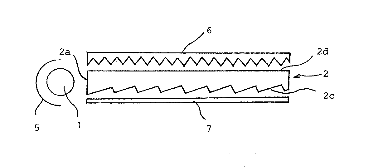
表1から、受光角αが0.1〜5度である本発明の実施例ではいずれも輝度及び均整度が高く、明るく均一な面光源になっていることが分かる。一方、受光角αが0度の比較例1では均整度は高いが輝度が低いこと、また、受光角αが5.5度と大きい比較例2では均整度が低く、受光角αが0.1〜5度の範囲外では輝度又は均整度が劣ることが分かる。 From Table 1, it can be seen that in the examples of the present invention having a light receiving angle α of 0.1 to 5 degrees, the brightness and the uniformity are high, and the surface light source is bright and uniform. On the other hand, Comparative Example 1 in which the light receiving angle α is 0 degrees has a high degree of uniformity but low brightness, and Comparative Example 2 in which the light receiving angle α is as large as 5.5 degrees has a low degree of uniformity and the light receiving angle α is 0. It can be seen that the brightness or the degree of uniformity is inferior outside the range of 1 to 5 degrees.
実施例6〜7及び比較例3〜5
長辺70mm、短辺45mmで短辺側を入射面2aとし、入射面2aの厚み0.8mmとし、反入射面側2bの厚みを0.5mmとした楔状アクリル板を準備した。
比較例3では、出射面に50μmピッチで頂角90度の2等辺三角形形状のプリズム形状をプリズムの稜線が長辺に平行になるようUV硬化樹脂(十条ケミカル(株)製GA4100RL−A)を用いて作製したプリズム形状をアクリル板に密着させた後UV照射機に通し硬化接着した。比較例3の90度の直角三角形の場合は、H/Wは1/2になる。
Examples 6-7 and Comparative Examples 3-5
A wedge-shaped acrylic plate having a long side of 70 mm, a short side of 45 mm, the short side as the
In Comparative Example 3, a prismatic shape of an isosceles triangle having an apex angle of 90 degrees at a pitch of 50 μm on the exit surface is made of UV curable resin (GA4100RL-A manufactured by Jujo Chemical Co., Ltd.) so that the prism ridge line is parallel to the long side. The prism shape produced using this was adhered to an acrylic plate and then cured and adhered through a UV irradiator. In the case of the 90-degree right triangle of Comparative Example 3, H / W is ½.
比較例4では、出射面に比較例3のプリズム形状の三角形状の先端に曲線を付けたレンズ形状を使用した。このレンズ形状の形状を形状測定機で測定すると凸部の高さHが17μmで1単位のレンズの幅Wは48μmであった。従って、この場合のH/Wは1/2.8になる。 In Comparative Example 4, a lens shape having a curved triangle-shaped tip of the prism shape of Comparative Example 3 was used on the exit surface. When this lens shape was measured with a shape measuring machine, the height H of the convex portion was 17 μm, and the width W of one unit of lens was 48 μm. Accordingly, the H / W in this case is 1 / 2.8.
比較例5では、反射面に実施例3で反射面に使用したのと同じプリズム形状を使用して、出射面にはレンズ列のない平面を使用した。 In Comparative Example 5, the same prism shape as that used for the reflecting surface in Example 3 was used for the reflecting surface, and a plane without a lens array was used for the emitting surface.
実施例6では、出射面に比較例4と同じレンズ形状を使用し、反射面に比較例5と同じプリズム形状を使用した。 In Example 6, the same lens shape as that of Comparative Example 4 was used on the exit surface, and the same prism shape as that of Comparative Example 5 was used on the reflecting surface.
実施例7では、出射面に使用したレンズ形状を形状測定機で測定すると凸部の高さHが11μmで1単位のレンズの幅Wは48μmであった。従って、この場合のH/Wは1/4.4になる。 In Example 7, when the lens shape used on the exit surface was measured with a shape measuring machine, the height H of the convex portion was 11 μm and the width W of one unit of lens was 48 μm. Therefore, H / W in this case is 1 / 4.4.
面光源装置は実施例1〜6と同様の方法で作成し、同様の方法で点灯して輝度を測定した。
表2に測定結果を示すが、表2中の輝度の値は25分割の輝度の平均値である。
The surface light source device was created by the same method as in Examples 1 to 6, and turned on by the same method to measure the luminance.
The measurement results are shown in Table 2. The luminance values in Table 2 are average values of the luminance in 25 divisions.
表2の結果より、実施例6及び7では輝度が高く、且つ均整度が高いことが分かる。一方、比較例3、4では輝度、均整度とも低いことが分かる。また、比較例3ではLEDからの4本のビームの明暗線が目立った。比較例5では4本のビームの明暗線が更に目立ち、輝度を測定し平均輝度を出すのは意味がないと判断し測定不能とした。 From the results of Table 2, it can be seen that Examples 6 and 7 have high brightness and high level of uniformity. On the other hand, in Comparative Examples 3 and 4, it can be seen that both the luminance and the degree of uniformity are low. Further, in Comparative Example 3, the bright and dark lines of four beams from the LED were conspicuous. In Comparative Example 5, the bright and dark lines of the four beams were more conspicuous, and it was judged impossible to measure the luminance and obtain the average luminance, so that the measurement was impossible.
実施例8〜9
出射面には実施例6と同じレンズ形状のレンズ幅Wが48μm、凸部の高さHが17μmのH/Wは1/2.8となる2等辺三角形の先端が曲線化した断面形状を入射面に垂直に配備したレンズ列を持ち、反射面には、100μmピッチの受光角αが1.6度、他の一面の角βが45度の断面を持つ不等辺三角形のプリズム列と90μmピッチの平坦部が交互に存在する形状を備えた実施例6〜7と同様の長短辺を有する楔型の導光体をアクリル樹脂を用いて射出成形によって製作した。
前記導光体を実施例1〜6と同様の方法で面光源装置を作成し、同様の方法で点灯して輝度を測定した結果を表3に実施例8として示した。また、出射面と反射面を逆に使用して、測定した結果を表3の実施例9として示した。
Examples 8-9
The exit surface has the same lens shape as in Example 6 with a lens width W of 48 μm, a convex height H of 17 μm and a H / W of 1/2. It has a lens array arranged perpendicularly to the entrance surface, and the reflective surface has a 100 μm pitch receiving angle α of 1.6 degrees and a non-equal triangular prism array having a cross section with an angle β of 45 degrees of the other surface and 90 μm. A wedge-shaped light guide having the same long and short sides as in Examples 6 to 7 having a shape in which flat portions of pitch are alternately present was manufactured by injection molding using an acrylic resin.
A surface light source device was prepared for the light guide in the same manner as in Examples 1 to 6, and the brightness was measured by lighting in the same manner. Moreover, the measurement result was shown as Example 9 of Table 3 using the output surface and the reflective surface in reverse.
表3の結果より、出射面に、入射面に対し直角方向に延びる凸部を形成したレンズ形状を使用した実施例8の方が、反射面に同レンズ形状を使用した実施例9より輝度が高いことが分かる。しかしながら、実施例9でも相当の高輝度が得られており、従って、出射面と反射面を入れ替えても良いことが分かる。 From the results of Table 3, the brightness of Example 8 using a lens shape in which a convex portion extending in a direction perpendicular to the entrance surface is formed on the exit surface is higher than that of Example 9 using the same lens shape on the reflection surface. I understand that it is expensive. However, even in Example 9, a considerably high luminance is obtained, and thus it can be seen that the exit surface and the reflection surface may be interchanged.
1 点状光源
2 導光体
2a 入射面
2b 反入射面
2c 反射面
2d 出射面
01〜05 光路
5 反射板
6 プリズムフィルム
7 反射板(平板)
(A) 入射面に対し略直角方向に延びる凸部及び/又は凹部の曲面を有する多数のレンズ列
(B) 入射面に対し略平行方向に延びる多数の非対称のレンズ列又はプリズム列
S1 光源側へ0.1〜5度の角度αを有する傾斜面
S2 任意の角度βを有する傾斜面
1-
(A) Multiple lens rows having convex and / or concave curved surfaces extending in a direction substantially perpendicular to the incident surface (B) Multiple asymmetric lens rows or prism rows extending in a direction substantially parallel to the incident surface S1 Light source side An inclined surface having an angle α of 0.1 to 5 degrees to the angle S2 An inclined surface having an arbitrary angle β
Claims (5)
Priority Applications (1)
| Application Number | Priority Date | Filing Date | Title |
|---|---|---|---|
| JP2004065294A JP4394977B2 (en) | 2004-03-09 | 2004-03-09 | Surface light source device |
Applications Claiming Priority (1)
| Application Number | Priority Date | Filing Date | Title |
|---|---|---|---|
| JP2004065294A JP4394977B2 (en) | 2004-03-09 | 2004-03-09 | Surface light source device |
Publications (2)
| Publication Number | Publication Date |
|---|---|
| JP2005259361A JP2005259361A (en) | 2005-09-22 |
| JP4394977B2 true JP4394977B2 (en) | 2010-01-06 |
Family
ID=35084899
Family Applications (1)
| Application Number | Title | Priority Date | Filing Date |
|---|---|---|---|
| JP2004065294A Expired - Lifetime JP4394977B2 (en) | 2004-03-09 | 2004-03-09 | Surface light source device |
Country Status (1)
| Country | Link |
|---|---|
| JP (1) | JP4394977B2 (en) |
Families Citing this family (61)
| Publication number | Priority date | Publication date | Assignee | Title |
|---|---|---|---|---|
| CN100561312C (en) * | 2006-03-22 | 2009-11-18 | 鸿富锦精密工业(深圳)有限公司 | Light guide plate and backlight module |
| JP2008066014A (en) | 2006-09-05 | 2008-03-21 | Enplas Corp | Light guide plate, surface light source, and image display device |
| US8047697B2 (en) | 2007-09-10 | 2011-11-01 | Sharp Kabushiki Kaisha | Backlight |
| KR100932304B1 (en) * | 2007-10-30 | 2009-12-16 | 제일모직주식회사 | Light guide plate for backlight unit having an asymmetric prism on the back and liquid crystal display using the same |
| US8220981B2 (en) | 2008-05-27 | 2012-07-17 | Lg Electronics Inc. | Liquid crystal display having a plurality of modules |
| WO2009145548A2 (en) | 2008-05-27 | 2009-12-03 | Lg Electronics Inc. | Led back-light unit and liquid crystal display device using the same |
| WO2010126226A2 (en) * | 2009-04-27 | 2010-11-04 | Lg Electronics Inc. | Back light unit and display device using the same |
| WO2010147294A1 (en) | 2009-06-15 | 2010-12-23 | 엘지전자 주식회사 | Display device |
| KR101660721B1 (en) | 2009-06-15 | 2016-09-29 | 엘지전자 주식회사 | Light emitting diode package, and back-light unit and liquid crystal display device using the same |
| WO2010147293A1 (en) | 2009-06-15 | 2010-12-23 | 엘지전자 주식회사 | Display device |
| KR101628366B1 (en) | 2009-07-06 | 2016-06-08 | 엘지전자 주식회사 | optical assembly, backlight unit having the same, and display apparatus thereof |
| KR100966640B1 (en) * | 2009-07-01 | 2010-06-29 | 주식회사 엘엠에스 | Optical sheet and optical device having the same |
| JP2011018619A (en) * | 2009-07-10 | 2011-01-27 | Sony Corp | Display device and surface lighting system |
| KR20110014869A (en) * | 2009-08-06 | 2011-02-14 | 엘지전자 주식회사 | Backlight unit and display device using same |
| KR20110017581A (en) * | 2009-08-14 | 2011-02-22 | 엘지전자 주식회사 | Optical assembly, backlight unit and display device having same |
| JP5593653B2 (en) * | 2009-08-25 | 2014-09-24 | 凸版印刷株式会社 | Light guide plate, backlight unit and display device |
| KR101611616B1 (en) | 2009-08-28 | 2016-04-11 | 엘지전자 주식회사 | Backlight unit and display apparatus thereof |
| BR112012008090A2 (en) * | 2009-08-27 | 2019-09-24 | Sharp Kk | backlight system and liquid crystal display device using the same. |
| KR20110023059A (en) * | 2009-08-28 | 2011-03-08 | 엘지전자 주식회사 | Backlight unit and display device using same |
| WO2011043466A1 (en) * | 2009-10-09 | 2011-04-14 | 三菱レイヨン株式会社 | Image display device |
| EP2354817A1 (en) | 2009-12-14 | 2011-08-10 | Lg Electronics Inc. | Backlight unit, and display apparatus including the backlight unit |
| JP5664100B2 (en) * | 2010-10-07 | 2015-02-04 | ソニー株式会社 | Light emitting device and image display device |
| US20140041205A1 (en) | 2010-11-19 | 2014-02-13 | Reald Inc. | Method of manufacturing directional backlight apparatus and directional structured optical film |
| KR101775068B1 (en) | 2010-11-19 | 2017-09-06 | 리얼디 스파크, 엘엘씨 | Directional flat illuminators |
| TWI636283B (en) | 2012-05-18 | 2018-09-21 | 美商瑞爾D斯帕克有限責任公司 | Directional backlight, directional display device and control method thereof |
| US9235057B2 (en) | 2012-05-18 | 2016-01-12 | Reald Inc. | Polarization recovery in a directional display device |
| US9188731B2 (en) | 2012-05-18 | 2015-11-17 | Reald Inc. | Directional backlight |
| CN104380185B (en) | 2012-05-18 | 2017-07-28 | 瑞尔D斯帕克有限责任公司 | Directional backlight |
| US9594261B2 (en) | 2012-05-18 | 2017-03-14 | Reald Spark, Llc | Directionally illuminated waveguide arrangement |
| KR102059391B1 (en) | 2012-05-18 | 2019-12-26 | 리얼디 스파크, 엘엘씨 | Directional display apparatus |
| US9678267B2 (en) | 2012-05-18 | 2017-06-13 | Reald Spark, Llc | Wide angle imaging directional backlights |
| US9350980B2 (en) | 2012-05-18 | 2016-05-24 | Reald Inc. | Crosstalk suppression in a directional backlight |
| WO2014055695A1 (en) | 2012-10-02 | 2014-04-10 | Reald Inc. | Temporally multiplexed display with landscape and portrait operation modes |
| CN105008983B (en) | 2012-12-21 | 2018-08-07 | 瑞尔D斯帕克有限责任公司 | Metalens assembly for directional displays |
| JP6584008B2 (en) * | 2013-02-22 | 2019-10-02 | リアルディー スパーク エルエルシー | Directional backlight |
| EP3011734A4 (en) | 2013-06-17 | 2017-02-22 | RealD Inc. | Controlling light sources of a directional backlight |
| US9239420B2 (en) | 2013-07-26 | 2016-01-19 | Dai Nippon Printing Co., Ltd. | Light guide plate, surface source device and transmission-type display device |
| KR102366346B1 (en) | 2013-10-14 | 2022-02-23 | 리얼디 스파크, 엘엘씨 | Light input for directional backlight |
| US9740034B2 (en) | 2013-10-14 | 2017-08-22 | Reald Spark, Llc | Control of directional display |
| WO2015073438A1 (en) | 2013-11-15 | 2015-05-21 | Reald Inc. | Directional backlights with light emitting element packages |
| WO2015200814A1 (en) | 2014-06-26 | 2015-12-30 | Reald Inc. | Directional privacy display |
| EP3204686B1 (en) | 2014-10-08 | 2019-07-17 | RealD Spark, LLC | Connection unit for a directional backlight |
| JP5867573B2 (en) * | 2014-12-03 | 2016-02-24 | ソニー株式会社 | Light emitting device |
| US10356383B2 (en) | 2014-12-24 | 2019-07-16 | Reald Spark, Llc | Adjustment of perceived roundness in stereoscopic image of a head |
| WO2016168345A1 (en) | 2015-04-13 | 2016-10-20 | Reald Inc. | Wide angle imaging directional backlights |
| WO2016191598A1 (en) | 2015-05-27 | 2016-12-01 | Reald Inc. | Wide angle imaging directional backlights |
| EP3369034B1 (en) | 2015-10-26 | 2023-07-05 | RealD Spark, LLC | Intelligent privacy system, apparatus, and method thereof |
| WO2017083526A1 (en) | 2015-11-10 | 2017-05-18 | Reald Inc. | Distortion matching polarization conversion systems and methods thereof |
| US10359561B2 (en) | 2015-11-13 | 2019-07-23 | Reald Spark, Llc | Waveguide comprising surface relief feature and directional backlight, directional display device, and directional display apparatus comprising said waveguide |
| EP3374692B1 (en) | 2015-11-13 | 2021-02-24 | RealD Spark, LLC | Wide angle imaging directional backlights |
| CN114143495B (en) | 2016-01-05 | 2025-07-15 | 瑞尔D斯帕克有限责任公司 | Gaze Correction for Multi-View Images |
| US10126575B1 (en) | 2017-05-08 | 2018-11-13 | Reald Spark, Llc | Optical stack for privacy display |
| US10303030B2 (en) | 2017-05-08 | 2019-05-28 | Reald Spark, Llc | Reflective optical stack for privacy display |
| CN110785694B (en) | 2017-05-08 | 2023-06-23 | 瑞尔D斯帕克有限责任公司 | Optical stacks for directional displays |
| TWI878209B (en) | 2017-09-15 | 2025-04-01 | 美商瑞爾D斯帕克有限責任公司 | Display device and a view angle control optical element for application to a display device |
| WO2019147762A1 (en) | 2018-01-25 | 2019-08-01 | Reald Spark, Llc | Reflective optical stack for privacy display |
| EP4214441A4 (en) | 2020-09-16 | 2024-08-28 | RealD Spark, LLC | VEHICLE EXTERIOR LIGHTING DEVICE |
| CN114488382A (en) | 2020-11-12 | 2022-05-13 | 中强光电股份有限公司 | Backlight module |
| CN114815032A (en) * | 2021-01-19 | 2022-07-29 | 光耀科技股份有限公司 | Light guide film and backlight module |
| US11966049B2 (en) | 2022-08-02 | 2024-04-23 | Reald Spark, Llc | Pupil tracking near-eye display |
| WO2024035796A1 (en) | 2022-08-11 | 2024-02-15 | Reald Spark, Llc | Anamorphic directional illumination device |
-
2004
- 2004-03-09 JP JP2004065294A patent/JP4394977B2/en not_active Expired - Lifetime
Also Published As
| Publication number | Publication date |
|---|---|
| JP2005259361A (en) | 2005-09-22 |
Similar Documents
| Publication | Publication Date | Title |
|---|---|---|
| JP4394977B2 (en) | Surface light source device | |
| US7334934B2 (en) | Light guide device and a backlight module using the same | |
| US9182530B2 (en) | Light guide plate with tapering unit optical elements | |
| US7522809B2 (en) | Planar light source and light guide for use therein | |
| US7804554B2 (en) | Surface emitting device and liquid crystal display | |
| US8159632B2 (en) | Surface light source element and image display apparatus including the same | |
| US8182131B2 (en) | Light guide plate and backlight unit having the same | |
| KR101607287B1 (en) | Light guiding plate, backlight assembly and display apparatus having the same | |
| US6971782B2 (en) | Illumination device and liquid crystal display device | |
| CN101191905B (en) | Light bar, backlight module and display using the same | |
| US9453958B2 (en) | Light guide plate and illumination apparatus | |
| CN100529809C (en) | Light conductive board and backlight module using same | |
| JP2010218693A (en) | Light guide plate for point-like light source | |
| CN104334962B (en) | Illuminator | |
| US7766533B2 (en) | Illumination module, and a display and general lighting apparatus using the same | |
| JP2005085671A (en) | Light guide plate and plane light source device | |
| JP2005353406A (en) | Light guide plate | |
| JP5685099B2 (en) | Surface light source element and display device including the same | |
| JP2004111352A (en) | Surface light source device and light guide used therein | |
| JP2008218418A (en) | Surface light source device and light guide used therefor | |
| CN105527672A (en) | Area light source device, display device and electronic device | |
| JP2001023423A (en) | Flat light source unit | |
| JP2010044921A (en) | Plane light source element and light control member used for this as well as image display using this | |
| US9075176B2 (en) | Light guide plate and planar lighting device | |
| JP2009158468A (en) | Backlight |
Legal Events
| Date | Code | Title | Description |
|---|---|---|---|
| A621 | Written request for application examination |
Free format text: JAPANESE INTERMEDIATE CODE: A621 Effective date: 20070219 |
|
| A977 | Report on retrieval |
Free format text: JAPANESE INTERMEDIATE CODE: A971007 Effective date: 20090129 |
|
| A131 | Notification of reasons for refusal |
Free format text: JAPANESE INTERMEDIATE CODE: A131 Effective date: 20090210 |
|
| A521 | Request for written amendment filed |
Free format text: JAPANESE INTERMEDIATE CODE: A523 Effective date: 20090331 |
|
| TRDD | Decision of grant or rejection written | ||
| A01 | Written decision to grant a patent or to grant a registration (utility model) |
Free format text: JAPANESE INTERMEDIATE CODE: A01 Effective date: 20090929 |
|
| A01 | Written decision to grant a patent or to grant a registration (utility model) |
Free format text: JAPANESE INTERMEDIATE CODE: A01 |
|
| A61 | First payment of annual fees (during grant procedure) |
Free format text: JAPANESE INTERMEDIATE CODE: A61 Effective date: 20091016 |
|
| R150 | Certificate of patent or registration of utility model |
Ref document number: 4394977 Country of ref document: JP Free format text: JAPANESE INTERMEDIATE CODE: R150 Free format text: JAPANESE INTERMEDIATE CODE: R150 |
|
| FPAY | Renewal fee payment (event date is renewal date of database) |
Free format text: PAYMENT UNTIL: 20121023 Year of fee payment: 3 |
|
| FPAY | Renewal fee payment (event date is renewal date of database) |
Free format text: PAYMENT UNTIL: 20121023 Year of fee payment: 3 |
|
| FPAY | Renewal fee payment (event date is renewal date of database) |
Free format text: PAYMENT UNTIL: 20131023 Year of fee payment: 4 |
|
| R250 | Receipt of annual fees |
Free format text: JAPANESE INTERMEDIATE CODE: R250 |
|
| R250 | Receipt of annual fees |
Free format text: JAPANESE INTERMEDIATE CODE: R250 |
|
| R250 | Receipt of annual fees |
Free format text: JAPANESE INTERMEDIATE CODE: R250 |
|
| R250 | Receipt of annual fees |
Free format text: JAPANESE INTERMEDIATE CODE: R250 |
|
| R250 | Receipt of annual fees |
Free format text: JAPANESE INTERMEDIATE CODE: R250 |
|
| R250 | Receipt of annual fees |
Free format text: JAPANESE INTERMEDIATE CODE: R250 |
|
| RD02 | Notification of acceptance of power of attorney |
Free format text: JAPANESE INTERMEDIATE CODE: R3D02 |
|
| R250 | Receipt of annual fees |
Free format text: JAPANESE INTERMEDIATE CODE: R250 |
|
| R250 | Receipt of annual fees |
Free format text: JAPANESE INTERMEDIATE CODE: R250 |
|
| R250 | Receipt of annual fees |
Free format text: JAPANESE INTERMEDIATE CODE: R250 |
|
| R250 | Receipt of annual fees |
Free format text: JAPANESE INTERMEDIATE CODE: R250 |
|
| R250 | Receipt of annual fees |
Free format text: JAPANESE INTERMEDIATE CODE: R250 |
|
| R250 | Receipt of annual fees |
Free format text: JAPANESE INTERMEDIATE CODE: R250 |
|
| EXPY | Cancellation because of completion of term |