JP2017178320A - Attaching method and removing method of interior bag, and interior bag and jig used in the method - Google Patents
Attaching method and removing method of interior bag, and interior bag and jig used in the method Download PDFInfo
- Publication number
- JP2017178320A JP2017178320A JP2016063340A JP2016063340A JP2017178320A JP 2017178320 A JP2017178320 A JP 2017178320A JP 2016063340 A JP2016063340 A JP 2016063340A JP 2016063340 A JP2016063340 A JP 2016063340A JP 2017178320 A JP2017178320 A JP 2017178320A
- Authority
- JP
- Japan
- Prior art keywords
- interior bag
- bag
- top plate
- suction
- shaped
- Prior art date
- Legal status (The legal status is an assumption and is not a legal conclusion. Google has not performed a legal analysis and makes no representation as to the accuracy of the status listed.)
- Granted
Links
Images


Landscapes
- Packages (AREA)
Abstract
【課題】クローズ型のドラム缶に装着する密閉型の内装袋の装着方法において、内装袋に傷や皺などが発生せずに、スムーズに装着できる方法を提供すること。
【解決手段】全体が可撓性を有する内装袋1を平板状の内装袋11に形成する工程と、平板状の内装袋11の両側辺から内側に向けてロール状に丸めて全体を上下に長い棒状の内装袋12とする工程と、棒状の内装袋12を缶体20の大栓24から挿入して内装袋の筒口4を大栓24に係止させる工程と、缶体の小栓25を通じて缶体20内部の空気を吸引することで、棒状の内装袋12を拡張させる工程とからなる缶体20への内装袋1の装着方法。
【選択図】図8An object of the present invention is to provide a method for mounting a closed type interior bag to be mounted on a closed drum can so that the interior bag can be smoothly mounted without causing scratches or wrinkles.
SOLUTION: A step of forming a flexible inner bag 1 into a flat inner bag 11 and a roll of the flat inner bag 11 from both sides to the inner side so that the whole is up and down. A step of forming a long rod-shaped inner bag 12, a step of inserting the rod-shaped inner bag 12 from the large plug 24 of the can body 20 and locking the tube port 4 of the inner bag to the large plug 24, and a small plug 25 of the can body A method of attaching the interior bag 1 to the can body 20 comprising a step of expanding the rod-shaped interior bag 12 by sucking air inside the can body 20 through the through hole.
[Selection] Figure 8
Description
この発明は、クローズ型ドラム缶等の密閉型硬質缶体の内部に可撓性のある内装袋を装着する方法等に関し、更に詳しくは、内装袋の保管時や輸送時に場所を取らず、かつ、缶体への装着や取り外しもきわめて容易となる方法や、その方法に使用される内装袋や治具に関するものである。 The present invention relates to a method of mounting a flexible interior bag inside a sealed hard can body such as a closed drum can, and more specifically, does not take up space during storage or transportation of the interior bag, and The present invention relates to a method that makes attachment and detachment to a can body extremely easy, and an interior bag and a jig used in the method.
例えば、保形性を有するドラム缶等の缶体の内側に装着し、その内部に各種液体や粉体を収納し、これらの保存や輸送を行う可撓性の内装容器として合成樹脂袋が使用されており、これら内装袋の使用により、缶体の内壁に収納物が直接接触しないので、収納物を取り出した後、内装袋を缶体から取り出せば、缶体の内壁は収納物により汚染されておらず、使用後の缶体内部を洗浄することなく、再び他の内装袋を装着することで、他の種類の収納物でもそのまま続けて収納することができる。 For example, a synthetic resin bag is used as a flexible interior container that is mounted inside a can body such as a drum can having shape retention, stores various liquids and powders therein, and stores and transports them. The use of these interior bags prevents the stored items from coming into direct contact with the inner wall of the can body. Therefore, if the inner bag is taken out of the can body after the stored items are taken out, the inner wall of the can body is contaminated by the stored items. In addition, by installing another interior bag again without washing the inside of the can after use, other types of stored items can be stored as they are.
上記のような内装袋は、熱可塑性合成樹脂シートを用いた筒状胴部の下端に同じく熱可塑性合成樹脂製シートからなる底板を溶着することで有底状で上面開放の内装袋を成形したり(例えば、特許文献1参照)、またはこれに加えて筒状胴部の上端部に筒口用の開口を設けた天板を溶着することで密閉状の内装袋を形成するようにしていた(例えば、特許文献2参照)。 The interior bag as described above is formed into a bottomed and open interior bag by welding a bottom plate made of a thermoplastic synthetic resin sheet to the lower end of a cylindrical body portion using a thermoplastic synthetic resin sheet. (For example, refer to Patent Document 1), or in addition to this, a sealed inner bag is formed by welding a top plate provided with an opening for a tube opening at the upper end of the tube body ( For example, see Patent Document 2).
また、内装袋が収納されるドラム缶は、主として鋼鉄製やステンレス製、又は樹脂製で、数種類の大きさの規格があり、その外観は、図12に示すように、代表的なドラム缶(缶体20)では、円筒状の胴板21の周りを2本の輪帯22が設けられ、下端を円板状の地板(図示せず)で閉鎖し、上端には缶体の天板23が設けられ、この缶体の天板23には、収納物を入れる注入口としての大栓24と、換気口としての小栓25が設けられている。
In addition, the drum can in which the interior bag is stored is mainly made of steel, stainless steel, or resin, and there are several kinds of sizes. As shown in FIG. 12, a typical drum can (can body) 20), two
また、缶体20には、オープン型とクローズ型があり、前者オープン型は円筒状の胴板21と缶体の天板23を必要に応じて着脱自在としてあり、後者クローズ型は、円筒状の胴板21と缶体の天板23とを一体に接合して上下面を閉鎖したものである。
The
これらドラム缶等の缶体に内装袋を装着する際、まずオープン型ドラム缶の場合は、内装袋の底板を缶体の内底部に落とし込んだ後、治具等を用いるなど適宜方法で内装袋を広げて内装袋が缶体の内壁に密着するようにし、その後、上面開口の内装袋の場合は、缶体の上部開口部から突出している部分を缶体の外側に折り返して固定し、密閉型の内装袋の場合は、缶体の天板23の大栓24を内装袋の筒口に合致させるようにして缶体の天板23によって缶体20の蓋をする。
When installing an interior bag to a drum body such as a drum can, first, in the case of an open-type drum can, after dropping the bottom plate of the interior bag into the inner bottom of the can body, the interior bag is expanded by an appropriate method such as using a jig. The inner bag is in close contact with the inner wall of the can body. After that, in the case of the interior bag with the top opening, the portion protruding from the upper opening of the can body is folded back to the outside of the can body and fixed. In the case of the interior bag, the
また、後者のクローズ型のドラム缶の場合、内装袋を内部に装着するのは困難であり、クローズ型ドラム缶に対し内装袋の装着が必要となった場合、従来は内装袋をその可撓性を利用して小さく畳んでから缶体の天板23の大栓24を通じて缶内部に無理矢理押し込み、内装袋の筒口を大栓24に係合固定し、筒口を通じて内装袋の内部に空気を入れて膨らませるなどの方法で装着していた。
In the case of the latter closed type drum can, it is difficult to install the interior bag inside, and when it is necessary to attach the interior bag to the closed type drum can, conventionally, the interior bag has to be flexible. After it is folded in a small size, it is forcibly pushed into the can through the
ところで、缶体20の大栓24は狭く、ここに小さく畳んだ内装袋を通す際に、金属製の大栓24の開口部の縁に接触しながら入れることになり、内装袋に傷がつくことがあり、そのまま装着して使用すると、内装袋の傷口から収納物が漏れ出すおそれがあった。
By the way, the
また、内装袋を小さくする際に多数の皺や折れ目が生じてしまい、広げても皺や折れ目が多数残ってしまい、ドラム缶の内壁に内装袋がぴったりと納まらず、ドラム缶が持つ収納容量を減らすこともあった。 In addition, a lot of wrinkles and folds are generated when the inner bag is made smaller, and many wrinkles and folds remain even if it is widened, so the inner bag does not fit exactly on the inner wall of the drum can, and the storage capacity of the drum can There was also a reduction.
なお、内装袋を構成する材料の選択や改良による強度向上により、少々の折り曲げ等に対する耐性や缶体20の大栓24に通してもあまり傷がつかないことも可能となったが、それでも、内装袋を小さく畳んだ時に生じた折り目や皺などに起因する表面の段差が、大栓24を通る際に縁に引っ掛かり、スムーズな挿入ができなくなる問題があった。
In addition, the strength improvement by selection and improvement of the material constituting the interior bag has made it possible to withstand a small amount of bending and the like, and even if it passes through the
そのため、クローズ型ドラム缶への内装袋の装着作業には、細心の注意や経験と技術が必要であり、また、装着作業に時間が掛かるといった問題があった。 For this reason, the attaching work of the interior bag to the closed drum can requires careful attention, experience and technology, and the attaching work takes time.
この発明は上記のような課題を解決し、クローズ型のドラム缶に装着する密閉型の内装袋の装着方法において、使用前の状態では嵩が低くて輸送や保管時に低コストとなり、ドラム缶への装着時には、内装袋に傷や皺などが発生せずに、スムーズに装着でき、装着作業が容易となった内装袋の装着方法を提供することを課題とする。 The present invention solves the above-mentioned problems, and in a method for mounting a sealed interior bag to be mounted on a closed drum can, the bulk is low before use, and the cost is low during transportation and storage. It is an object of the present invention to provide a method for mounting an interior bag that can be smoothly mounted without causing scratches or wrinkles on the interior bag and that facilitates the mounting operation.
上記の目的を達成するため、請求項1の発明は、筒状胴部の上下端が円形状の天板及び底板により閉鎖され天板に筒口が設けられ全体が可撓性を有する内装袋を、クローズ型で上面に注入口としての大栓と吸気口としての小栓を有する缶体の内部へ装着する方法であって、
(1)天板を筒口のある一方半円部を外側にして他方半円部を内側になるよう山折りで2つ折り状態とし、底板を山折り又は谷折りで2つ折り状態とし、筒状胴部を前後を重ね合わせた上で少なくとも1本の横方向の折り曲げ線により折り畳んで全体が平板状となった平板状の内装袋を形成する工程と、
(2)前記平板状の内装袋の両側辺から内側に向けてロール状に丸めて全体を上下に長い棒状の内装袋とする工程と、
(3)前記棒状の内装袋を缶体の大栓から挿入して内装袋の筒口を大栓に係止させる工程と、
(4)缶体の小栓を通じて缶体内部の空気を吸引することで、棒状の内装袋を元の筒状体となるまで拡張させる工程と、からなるクローズ型の缶体への内装袋の装着方法である。
In order to achieve the above object, the invention according to
(1) The top plate is folded in two with a mountain fold so that one semicircular portion with a tube mouth is on the outside and the other semicircular portion is on the inside, and the bottom plate is folded in two with a mountain fold or a valley fold. A step of forming a flat interior bag in which the whole is flattened by folding at least one lateral folding line after overlapping the front and back parts,
(2) a step of rolling the plate-shaped interior bag from both sides to the inside so as to form a rod-shaped interior bag that is long in the vertical direction;
(3) inserting the rod-shaped interior bag from the large stopper of the can body and locking the tube opening of the interior bag to the large stopper;
(4) The step of expanding the rod-shaped interior bag to the original cylindrical body by sucking the air inside the can body through the can plug of the can body, and the interior bag to the closed type can body It is a mounting method.
請求項2の発明は、筒状胴部の上下端が円形状の天板及び底板により閉鎖され天板に筒口が設けられ全体が可撓性を有する内装袋を、クローズ型で上面に注入口としての大栓と吸気口としての小栓を有する缶体の内部から取り外す方法であって、
缶体の小栓を開けた状態で、内装袋の筒口を通じて内装袋内部の空気を吸引することで、内装袋を収縮させてから缶体の大栓から引き抜く、クローズ型の缶体からの内装袋の取り外し方法である。
The invention according to
The interior from the closed-type can body, with the can open the can body, by drawing the air inside the interior bag through the tube opening of the interior bag, and then pulling it out from the large stopper of the can body How to remove the bag.
請求項3の発明は、前記請求項1において使用される棒状の内装袋であって、
筒状胴部の上下端が円形状の天板及び底板により閉鎖され天板に筒口が設けられ全体が可撓性を有しており、
天板を筒口のある一方半円部を外側にして他方半円部を内側になるよう山折りで2つ折り状態で、底板を山折り又は谷折りで2つ折り状態で、筒状胴部を前後を重ね合わせた上で少なくとも1本の横方向の折り曲げ線により折り畳まれた状態であり、
両側辺から内側に向けて前記折り畳まれた状態の筒状胴部や天板及び底板をロール状に丸めたロール状部が2本形成され、全体を上下に長い棒状とした棒状の内装袋である。
Invention of
The upper and lower ends of the cylindrical body are closed by a circular top plate and a bottom plate, the top plate is provided with a cylindrical opening, and the whole has flexibility,
The top plate is folded in two with a mountain fold so that one semicircular part with the tube mouth is on the outside and the other semicircular part is on the inside, and the bottom plate is folded in two with a mountain fold or a valley fold. And is folded by at least one lateral fold line,
It is a rod-shaped interior bag in which two roll-shaped portions are formed by rolling the cylindrical body portion and the top plate and the bottom plate in the folded state from both sides toward the inside, and the whole is formed into a long rod shape is there.
請求項4の発明は、前記請求項1に記載のクローズ型の缶体への内装袋の装着方法又は前記請求項2に記載のクローズ型の缶体からの内装袋の取り外し方法における、空気の吸引に専ら使用される吸引治具であって、
多数の吸引孔を有する吸引部を有し、吸引ホースに接続される一方端に円形の鍔部を有し、他方端には緩衝材を設けた吸引治具である。
According to a fourth aspect of the present invention, in the method for mounting the inner bag on the closed type can body according to the first aspect or the method for removing the inner bag from the closed type can body according to the second aspect, A suction jig used exclusively for suction,
A suction jig having a suction part having a plurality of suction holes, having a circular flange at one end connected to the suction hose, and provided with a cushioning material at the other end.
以上のように、請求項1に記載の発明の内装袋の装着方法によれば、従来困難であったクローズ型のドラム缶等の缶体に対し、簡単な作業で内装袋を装着できて装着に熟練が不要となり、また装着時間の短縮等により低コストでの内装袋の装着が可能となる。
As described above, according to the mounting method of the interior bag of the invention described in
また、缶体の大栓に内装袋を通す際に、棒状の内装袋は、その側部はロール状に巻かれて全長にわたって表面に段差等がないので、大栓の縁に内装袋が引っ掛かったりせずにスムーズに挿入できるし、挿入の際に大栓の縁により内装袋が傷ついたりすることもない。 In addition, when the inner bag is passed through the large cap of the can, the side of the rod-shaped inner bag is rolled up so that there is no step on the surface over the entire length, so the inner bag is caught on the edge of the large plug. It can be inserted smoothly without being damaged, and the inner bag is not damaged by the edge of the large plug during insertion.
更に、内装袋は、折り曲げ部分が最小限で、かつロール巻きにより棒状としているので、内装袋に加わるストレスは極力避けており、内装袋を構成する合成樹脂に伸び等や皺の発生がなく、小栓の吸引により缶体内部で内装袋を拡張させた際も、皺や伸び等が発生しておらず、スムーズに元の円筒形状に戻るので、内装袋が缶体内面にぴったりと張り付き、装着された内装袋に皺が生じたり缶体内面との間にエアの残りが生じたりしない。 Furthermore, since the inner bag has a minimum bent portion and is made into a rod shape by roll winding, stress applied to the inner bag is avoided as much as possible, and the synthetic resin constituting the inner bag has no elongation or wrinkles, Even when the inner bag is expanded inside the can body by sucking the small stopper, no wrinkles or elongation occurs, and it returns smoothly to the original cylindrical shape, so the inner bag sticks tightly to the inner surface of the can body, There will be no wrinkles on the attached interior bag or air remaining between the inner surface of the can body.
請求項2に記載の発明の内装袋の取り外し方法によれば、簡単な作業で内装袋を取り外しができて作業に熟練が不要となり、また取り外し時間の短縮等により低コストでの内装袋の取り外しが可能となる。
According to the method for removing the interior bag of the invention described in
請求項3に記載の発明の内装袋によると、内装袋への最小限の折り畳み、即ち最小限のストレスによって円筒形状の内装袋が棒状となっており、棒状の内装袋を複数本を積んで輸送や保管することができ、輸送や保管時に嵩高くならずコスト低減につながると共に、その側部はロール状に巻かれたロール状部となっており、全長にわたって表面に段差等がなく大栓の縁に内装袋が引っ掛かったりせずにスムーズに挿入できるので、ドラム缶等の缶体への装着もスムーズかつ作業により損傷することもない。
According to the interior bag of the invention described in
請求項4に記載の吸引治具によれば、缶体への吸引作業において、小栓に押し付けることで鍔部が小栓の縁に被さり、外部からの吸気を遮断して効率的に吸引を行えると共に、先端側の緩衝材により吸引作業時に内装袋が治具に当たって内装袋が傷つくことを防止できる。
According to the suction jig of
以下、この発明の実施の形態を図示例と共に説明する。
図1は、この発明の装着方法で使用する内装袋の斜視図を示すものであり、内装袋1は、合成樹脂製で所定長さの筒状となった筒状胴部2の下端部に円板形状の底板3の周辺部を重ねて既知の手段にて溶着し、筒状胴部2の上端部には上面に貫通状の筒口4を設けた円板形状の天板5の周辺部を重ねて既知の手段にて溶着することで、筒状胴部2の上下端が天板5及び底板3で閉鎖されたクローズ状となっている。
Hereinafter, embodiments of the present invention will be described with reference to the drawings.
FIG. 1 shows a perspective view of an interior bag used in the mounting method of the present invention. The
これら筒状胴部2や底板3、天板5は、可撓性のある合成樹脂製とするが、材質や構造についても、特に限定されるものではなくPP、PE等適宜既知の材質のものを使用でき、要するに、筒状胴部2や底板3及び天板5については、可撓性があり、少々の折り曲げに耐えられ、必要なら加熱溶着して接着ができる材質のものであればく、また、複数の材料を多層にしたものであってもよい。
The
また、筒口4については、可撓性は有するが、後述のドラム缶の大栓に係合させるため鍔部を形成し、筒状胴部2や天板5よりは、ある程度の剛性を有する材料としておく。
In addition, the
なお、上記内装袋1における、筒状胴部2と底板3や天板5の既知の手段の溶着方法として、これら筒状胴部2と、底板3、天板5のいずれか片方または両方に図示していない溶着片を延長して設けて、これら溶着片と他方の部位とを熱溶着により接着することが考えられるが、特にそれらに限定されず、他の種々の公知の方法で接続することができる。
In addition, as a welding method of the known means of the
[棒状の内装袋の形成]
これら内装袋1は、そのままでは柱状体であり、輸送や保管の際に体積を取るので、それを防ぐため、図2乃至図6に示すような手順にて細長い棒状とする。まず、図2(A)で示すように、内装袋1の上端側については、天板5の中心部を通り筒口4を避けた任意の直線状の折り曲げ線5aを定め、天板5の周囲の筒状胴部2についてもこの折り曲げ線5aを若干延長しておいて、この折り曲げ線5aの部分を山折りにしてゆく。
[Formation of rod-shaped interior bag]
These
すると、図2(B)に示すように、円形状の天板5は折り曲げ線5aを境に筒口4を有する一方の半円部5bと他方の半円部5cとに別れ、半円部5cを半円部5bの下に来るように内部に折り込んでゆく。
Then, as shown in FIG. 2 (B), the circular
また、筒状胴部2における前記折り曲げ線5aと連続する2本の直線の折り曲げ線2aの部分を山折りにして、筒状胴部2を表裏重ね合わせた平板状にしてゆく。
Further, the portion of the two linear fold lines 2a that are continuous with the fold line 5a in the
更に、内装袋1の下端側については、底板3の中心部を通り、元の筒状体の時に天板5の折り曲げ線5aと平行な直線状の折り曲げ線3aを定め、底板3の周囲の筒状胴部2についてもこの折り曲げ線3aを若干延長しておいて、この折り曲げ線3aの部分を(外側から見て)谷折りにしてゆく(図2(B)参照)。なお、底板3の折り曲げ線3aは、図示実施形態では谷折りにしたが、山折りでもかまわない。
Furthermore, about the lower end side of the
すると、図3(C)(D)の断面図で示すように、天板5は、折り曲げ線5aの部分で別れた半円部5b、5cが折り畳まれ、その際、半円部5b、5cの内面側が重なるようになる。なお、同時に、筒状胴部2の上端部付近の折り曲げ線5aの延長部分もその内面同士が重なるようになる。
Then, as shown in the cross-sectional views of FIGS. 3C and 3D, the
一方、底板3は、折り曲げ線3aの部分で別れた半円部3b、3cが折り畳まれ、外面側が重なると共に、筒状胴部2の下端部付近の折り曲げ線3aの延長部分もその外面同士が重なってゆく(図3(C)(D)参照)。
On the other hand, the semicircular portions 3b and 3c separated from each other at the folding line 3a are folded on the
なお、前記天板5を通る折り曲げ線5aや底板3を通る折り曲げ線3aの長さは特に限定されないが、筒状胴部2の外周が天板5や底板3の直径の約3倍(π)であり、筒状胴部2が2つ折りになった際にその幅が天板5や底板3の直径の約1.5倍の幅となることや、折り曲げた際に内装袋1を構成する合成樹脂にストレスを与えないためには、内装袋1の直径(=天板5や底板3の直径)の1.3倍〜1.5倍当たりが好ましい。即ち、折り曲げ線5a、3aの筒状胴部2への延長部分の長さは、片側で内装袋1の直径の15〜25%程度となる。
The lengths of the fold line 5a passing through the
図3(D)のように、天板5の半円部5b、5cや底板3の半円部3b、3cをぴったり重ね合わせると共に、筒状胴部2も表裏を重ねて平板状とすることで、図4(E)に示すような平板状の内装袋11が形成される。
As shown in FIG. 3D, the semicircular portions 5b and 5c of the
この平板状の内装袋11に対し、続けて、図4(F)に示す筒状胴部2の中心付近で横方向の折り曲げ線2bにて折り曲げて平板状の内装袋11を更に半分の大きさにするが、折り曲げ線2bの本数は1本に限らず2本以上であってもよい。ただし、あまり重ね合わせすぎると、次工程のロール状部を形成するのが困難となるので、1〜3本程度が好ましい。なお、この際も、天板5の筒口4は外側になるように重ね合わせる。
With respect to the flat inner bag 11, the flat inner bag 11 is further halved by folding the flat inner bag 11 in the vicinity of the center of the
平板状の内装袋11を図4(F)で示した折り曲げ線2aにて折り曲げて、図5(G)に示す形状の縦寸法が小さくなった平板状の内装袋11となる。 The flat inner bag 11 is bent along the fold line 2a shown in FIG. 4F, so that the flat inner bag 11 having a smaller vertical dimension as shown in FIG. 5G is obtained.
次に、図5(H)(I)(J)(K)と順を追って示すように、平板状の内装袋11の側辺(筒状胴部2の折り曲げ線2aの部分)から内側に向けて横方向にロール状に丸めて左右にロール状部6を形成してゆく。
Next, as shown in FIG. 5H, (I), (J), and (K) in order, from the side of the flat inner bag 11 (the portion of the folding line 2a of the cylindrical body 2) to the inside. The roll-shaped
すると、ロール状部6は巻き取られるにつれて、筒状胴部2から天板5(裏面では底板3)の部分まで巻き込んでいくことになり、両側のロール状部6が中央に達した時は、2つのロール状部6はほぼ上下方向の全長に達しており、全体が上下に細長い棒状となり、両方のロール状部6を粘着テープで止める等適宜手段で固定することで、図6で示す棒状の内装袋12となる。
Then, as the roll-shaped
なお、後述の缶体への装着時に、筒口を缶体の大栓に係合しやすくしておくために、両ロール状部6を巻き込んで行って両ロール状部6を中央で合わせる直前に、図5(J)で示すように、筒口4を上に引き上げておいて、図5(K)で示すように、両ロール状部6の上側に筒口4が出るようにしておく。
In order to keep the tube opening easily engaged with the large stopper of the can body when it is attached to the can body, which will be described later, immediately before the two roll-
なお、ロール状部6のロール巻き方向は、図示実施形態のように、左右対称でもよいが、片方を裏面側にてロール状に巻いたロール状部6を形成するようにしてもよい。
In addition, although the roll winding direction of the roll-shaped
上記棒状の内装袋12は、細長い棒状であり、缶体に装着する使用前の保管時や輸送時には、棒状の内装袋12を横にして複数本重ねて置くことで嵩高くならず、保管や輸送の際のコスト低減に繋がる。 The rod-shaped interior bag 12 is in the shape of a long and narrow bar, and it is not bulky by storing a plurality of the rod-shaped interior bags 12 side by side when storing or transporting the can body before use. This leads to cost reduction during transportation.
[内装袋の缶体への装着方法]
次に上記棒状の内装袋12のドラム缶等の缶体へ装着する装着方法について図7乃至図10に基づいて説明する。
[How to attach the inner bag to the can]
Next, a mounting method for mounting the rod-shaped interior bag 12 on a can such as a drum can will be described with reference to FIGS.
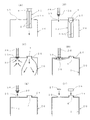
まず、図7に示すように、先に説明したクローズ型のドラム体としての缶体20に設けられた大栓24(注入口)と小栓25(換気口)を開口し、大栓24に棒状の内装袋12を挿入する。
First, as shown in FIG. 7, the large plug 24 (injection port) and the small plug 25 (ventilation port) provided in the
図8(A)に示すように、大栓24に棒状の内装袋12を通過させる際、棒状の内装袋12はその可撓性により狭まって通過するが、大栓24の縁に接する部分は、断面が略円形状のロール状部6の表面と接触しており、このロール状部6は最初から最後まで段差等も無いので、ひっかかりが無くスムーズに通過させることができるし、棒状の内装袋12が傷つくことも無い。
As shown in FIG. 8 (A), when passing the rod-shaped interior bag 12 through the
図8(B)に示すように、棒状の内装袋12を缶体20の大栓24に通し終えた後、大栓24に対して棒状の内装袋12の筒口4の鍔部を係合させる等適宜手段にて、棒状の内装袋12を缶体20に固定すると共に、缶体20の小栓25に対し、吸引ホース36に接続された吸引治具30を接続する。
As shown in FIG. 8B, after the rod-shaped interior bag 12 has been passed through the
吸引治具30は、図9に示すような構造であり、円錐の頂点側を切り取った断頭円錐形を逆向きにした形状で、全体が網目で構成されている吸引部31と、吸引部31の上端部に設けられた鍔部32と、吸引部31の下端部に設けられた緩衝材33と、吸引部31と鍔部32の境目に設けられた緩衝材34と、鍔部32の上側にて吸引部31と導通している吸引ホース接続部35とからなる。
The
前記吸引部31は、この実施形態では金属の金網で構成したが、金網に限定されるものではなく、要するに、多数の吸気用の吸引孔を設けたものであれば特にその構成は限定されるものではない。
In this embodiment, the
鍔部32は、缶体20の小栓25に蓋をし、効率よくエアーを吸引するためのものであり、小栓25の直径よりも大きくしておく。なお、後述の内装袋1の取り外し方法にも兼用するためには、鍔部32は大栓24の直径よりも大きくしておくことが好ましい。
The
吸引部31の下端に設けた緩衝材33は、吸引作業時に内装袋1が吸引部31に当たって傷つかないようにするためのものであり、更に本実施形態では、小栓25の縁に吸引部31が当たって傷つかないように、念のため吸引部31の上端部側にも緩衝材34を設けてある。
The cushioning
上記のような吸引治具30を缶体20の小栓25に押さえつけて鍔部32により空気漏れを防ぎながら、吸引ホース36の根元側に接続された図示していない適宜吸引装置により吸引を行い、図8(C)に示すように、吸引治具30を通じて缶体20内の空気を吸引し、折り畳まれた棒状の内装袋12を拡張させてゆく。
While holding the
図8(D)で示すように、棒状の内装袋12が元の円筒状の内装袋1の状態まで広がった時、微調整で吸引治具30を上下左右に動かしながら内装袋1にテンションを与えることにより、内装袋1の広がりの不十分な個所が内装袋1の揺れにより缶体20の内壁との隙間の空気を逃がし、内装袋1は缶体20の内壁にぴったりと装着される。
As shown in FIG. 8D, when the rod-shaped interior bag 12 spreads to the original cylindrical
この作業の際、吸引治具30に設けられた緩衝材34や35が、吸引部31と内装袋1、又は吸引部31と小栓25とのぶつかり合いによる衝撃を和らげて、内装袋1や吸引部31の損傷を防ぐ。
During this operation, the cushioning
図8(E)に示すように、内装袋1を広げた後、吸引治具30を小栓25から取り去り、続けて、図8(F)に示すように、大栓24に大栓用蓋26、小栓25に小栓用蓋27を、それぞれねじ止め等により装着して内装袋装着済みのドラム缶(缶体20)となる。
As shown in FIG. 8 (E), after the
図10は、図9で示した吸引治具30の種々の例を示すもので、図10(A)は吸引ホース36側が雄ネジ状のアダプタ37として吸引治具30側の吸引ホース接続部35がアダプタ37の雄ネジと合う雌ネジで固定する方法、図10(B)は(A)と同構造の接続であるが吸引ホース36側が太い場合を考慮してアダプタ37の形状を工夫した例、図10(C)は吸引治具30側の吸引ホース接続部35を雄ネジとした例、図10(D)は(C)と同構造の接続であるが吸引ホース36側が太い場合を考慮してアダプタ37の形状を工夫した例、図10(E)は、吸引治具30側の吸引ホース接続部35を複数のテンション棒で構成し、吸引ホース36側のアダプタ37の内部からテンションをかけて固定する方法である。
FIG. 10 shows various examples of the
なお、上記図10で示したものはあくまで吸引治具30の吸引ホース接続部35と吸引ホース36のアダプタ37の例示であって、要するに吸引治具30の吸引部31に吸引力を与えるものであれば特にその構造は限定されるものではない。
10 is only an example of the suction
[内装袋の缶体からの取り外し方法]
次に上記方法にて内装袋1を装着した缶体20を、各種収納物の保管や輸送に使用した後、収納物を取り出し、缶体20の内装袋1を取り替えるために、缶体20から内装袋1を取り外す方法について図11に基づいて説明する。
[How to remove the inner bag from the can]
Next, after using the
図11(A)に示すように、缶体20の大栓24から大栓用蓋26を、小栓25から小栓用蓋27をそれぞれ取り外し、次に、図11(B)に示すように、大栓24に先に示した吸引治具30を取り付ける。
As shown in FIG. 11 (A), the
図11(C)に示すように、この状態で吸引治具30を通じて内装袋1の内部の空気を吸引し、図11(D)のように内装袋1を収縮させてゆく。
As shown in FIG. 11C, in this state, the air inside the
図11(E)に示すように、内装袋1が収縮しきったら、吸引治具30を取り外し、続けて図11(F)に示すように、筒口4を上に引っ張り上げることによって、内装袋1を大栓24を通じて缶体20の外に取り出す。
As shown in FIG. 11 (E), when the
1 内装袋
2 筒状胴部
2a、2b 折り曲げ線
3 底板
3a 折り曲げ線
3b、3c 半円部
4 筒口
5 天板
5a 折り曲げ線
5b、5c 半円部
6 ロール状部
11 平板状の内装袋
12 棒状の内装袋
20 缶体
21 胴板
22 輪帯
23 缶体の天板
24 大栓
25 小栓
30 吸引治具
31 吸引部
32 鍔部
33 緩衝材
34 緩衝材
35 吸引ホース接続部
36 吸引ホース
DESCRIPTION OF
Claims (4)
(1)天板5を筒口4のある一方半円部5bを外側にして他方半円部5cを内側になるよう山折りで2つ折り状態とし、底板3を山折り又は谷折りで2つ折り状態とし、筒状胴部2を前後を重ね合わせた上で少なくとも1本の横方向の折り曲げ線2bにより折り畳んで全体が平板状となった平板状の内装袋11を形成する工程と、
(2)前記平板状の内装袋11の両側辺から内側に向けてロール状に丸めて全体を上下に長い棒状の内装袋12とする工程と、
(3)前記棒状の内装袋12を缶体20の大栓24から挿入して内装袋の筒口4を大栓24に係止させる工程と、
(4)缶体の小栓25を通じて缶体20内部の空気を吸引することで、棒状の内装袋12を元の筒状体となるまで拡張させる工程と、からなることを特徴とするクローズ型の缶体への内装袋の装着方法。 The upper and lower ends of the cylindrical body portion 2 are closed by a circular top plate 5 and a bottom plate 3, and the top plate 5 is provided with a cylindrical port 4. A method of mounting the inside of the can body 20 having a large plug 24 and a small plug 25 as an air inlet,
(1) The top plate 5 is folded in two with a mountain fold so that one semicircular portion 5b with the tube port 4 is on the outside and the other semicircular portion 5c is on the inside, and the bottom plate 3 is folded in two with a mountain fold or a valley fold. And forming a flat-shaped interior bag 11 that is entirely flat by folding the cylindrical body 2 with the at least one lateral fold line 2b after overlapping the front and rear,
(2) a step of rounding the flat inner bag 11 from both sides toward the inside to form a rod-shaped inner bag 12 that is long in the vertical direction;
(3) inserting the rod-shaped interior bag 12 from the large plug 24 of the can body 20 and locking the tube port 4 of the interior bag to the large plug 24;
(4) A closed type comprising: a step of expanding the rod-shaped interior bag 12 to the original cylindrical body by sucking air inside the can body 20 through the can plug 25 of the can body. How to attach the interior bag to the can body.
缶体の小栓25を開けた状態で、内装袋の筒口4を通じて内装袋1内部の空気を吸引することで、内装袋1を収縮させてから缶体20の大栓24から引き抜くことを特徴とするクローズ型の缶体からの内装袋の取り外し方法。 The upper and lower ends of the cylindrical body portion 2 are closed by a circular top plate 5 and a bottom plate 3, and the top plate 5 is provided with a cylindrical port 4. A method of removing from the inside of the can body 20 having a large plug 24 and a small plug 25 as an air inlet,
With the small cap 25 of the can body opened, the air inside the interior bag 1 is sucked through the tube port 4 of the interior bag so that the interior bag 1 is contracted and then pulled out from the large plug 24 of the can body 20. How to remove the interior bag from the closed can body.
筒状胴部2の上下端が円形状の天板5及び底板3により閉鎖され天板5に筒口4が設けられ全体が可撓性を有しており、
天板5を筒口4のある一方半円部5bを外側にして他方半円部5cを内側になるよう山折りで2つ折り状態で、底板3を山折り又は谷折りで2つ折り状態で、筒状胴部2を前後を重ね合わせた上で少なくとも1本の横方向の折り曲げ線2bにより折り畳まれた状態であり、
両側辺から内側に向けて前記折り畳まれた状態の筒状胴部2や天板5及び底板3をロール状に丸めたロール状部6が2本形成され、全体を上下に長い棒状としたことを特徴とする棒状の内装袋。 A rod-shaped interior bag 12 used in claim 1,
The upper and lower ends of the cylindrical body portion 2 are closed by a circular top plate 5 and a bottom plate 3, and a cylindrical port 4 is provided on the top plate 5, and the whole has flexibility,
The top plate 5 is folded in two with a mountain fold so that one semicircular portion 5b with the tube port 4 is on the outside and the other semicircular portion 5c is on the inside, and the bottom plate 3 is folded in two with a mountain fold or a valley fold. A state in which the cylindrical body 2 is folded by at least one lateral fold line 2b after overlapping the front and rear,
Two roll-shaped portions 6 formed by rolling the cylindrical body portion 2 and the top plate 5 and the bottom plate 3 in the folded state from both sides toward the inside are formed into a rod shape that is long vertically. A rod-shaped interior bag characterized by
多数の吸引孔を有する吸引部31を有し、吸引ホース35に接続される一方端に円形の鍔部32を有し、他方端には緩衝材33を設けたことを特徴とする吸引治具。 The suction used exclusively for air suction in the method for attaching the inner bag to the closed type can body according to claim 1 or the method for removing the inner bag from the closed type can body according to claim 2. A jig 30,
A suction jig having a suction part 31 having a number of suction holes, a circular flange 32 at one end connected to a suction hose 35, and a buffer material 33 at the other end .
Priority Applications (1)
| Application Number | Priority Date | Filing Date | Title |
|---|---|---|---|
| JP2016063340A JP6713311B2 (en) | 2016-03-28 | 2016-03-28 | Method of attaching and detaching inner bag and inner bag used in the method |
Applications Claiming Priority (1)
| Application Number | Priority Date | Filing Date | Title |
|---|---|---|---|
| JP2016063340A JP6713311B2 (en) | 2016-03-28 | 2016-03-28 | Method of attaching and detaching inner bag and inner bag used in the method |
Publications (2)
| Publication Number | Publication Date |
|---|---|
| JP2017178320A true JP2017178320A (en) | 2017-10-05 |
| JP6713311B2 JP6713311B2 (en) | 2020-06-24 |
Family
ID=60004945
Family Applications (1)
| Application Number | Title | Priority Date | Filing Date |
|---|---|---|---|
| JP2016063340A Active JP6713311B2 (en) | 2016-03-28 | 2016-03-28 | Method of attaching and detaching inner bag and inner bag used in the method |
Country Status (1)
| Country | Link |
|---|---|
| JP (1) | JP6713311B2 (en) |
Cited By (3)
| Publication number | Priority date | Publication date | Assignee | Title |
|---|---|---|---|---|
| JP2019529271A (en) * | 2016-09-23 | 2019-10-17 | マウザー−ヴェルケ ゲゼルシャフト ミット ベシュレンクテル ハフツングMauser−Werke GmbH | Drum with stopper with liner and method for manufacturing the same |
| WO2019221367A1 (en) * | 2018-05-17 | 2019-11-21 | 주식회사 이너보틀 | Method and apparatus for manufacturing container |
| KR20200119755A (en) * | 2018-05-17 | 2020-10-20 | (주)이너보틀 | Method for manufacturing contanier and apparatus for manufacturing contanier |
Citations (10)
| Publication number | Priority date | Publication date | Assignee | Title |
|---|---|---|---|---|
| JPS548084A (en) * | 1977-06-21 | 1979-01-22 | Masato Fukushima | Compound container and method of using pouch fitted in compound container |
| JPS5548050A (en) * | 1978-09-26 | 1980-04-05 | Yamato Tekkosho Kk | Method of installing interior finish bag of vessel* such as* drum can* etc* |
| JPS6096228U (en) * | 1983-12-07 | 1985-07-01 | フロイント産業株式会社 | Double layer container for liquid storage |
| JP2003335366A (en) * | 2002-05-17 | 2003-11-25 | Nisshin Sansho Kk | Inner packaging container |
| JP2003341729A (en) * | 2002-05-29 | 2003-12-03 | Nisshin Sansho Kk | Method of filling drum with inner packaging container and inner packaging container |
| JP2005231727A (en) * | 2004-01-22 | 2005-09-02 | Fuji Photo Film Co Ltd | Inner bag for transport tank, and its manufacturing method |
| JP2006044731A (en) * | 2004-08-04 | 2006-02-16 | Nisshin Sansho Kk | Manufacturing method of inner container for use in drum, and the inner container |
| US20100032053A1 (en) * | 2008-08-01 | 2010-02-11 | Mokchuan Chong | Container lining device and method for using the same |
| JP2013060220A (en) * | 2011-09-14 | 2013-04-04 | Tokyo Ohka Kogyo Co Ltd | Method for filling liquid container with liquid |
| JP2015504028A (en) * | 2012-02-06 | 2015-02-05 | アドバンスド テクノロジー マテリアルズ,インコーポレイテッド | Folded liner for use with an overpack and method of manufacturing the same |
-
2016
- 2016-03-28 JP JP2016063340A patent/JP6713311B2/en active Active
Patent Citations (10)
| Publication number | Priority date | Publication date | Assignee | Title |
|---|---|---|---|---|
| JPS548084A (en) * | 1977-06-21 | 1979-01-22 | Masato Fukushima | Compound container and method of using pouch fitted in compound container |
| JPS5548050A (en) * | 1978-09-26 | 1980-04-05 | Yamato Tekkosho Kk | Method of installing interior finish bag of vessel* such as* drum can* etc* |
| JPS6096228U (en) * | 1983-12-07 | 1985-07-01 | フロイント産業株式会社 | Double layer container for liquid storage |
| JP2003335366A (en) * | 2002-05-17 | 2003-11-25 | Nisshin Sansho Kk | Inner packaging container |
| JP2003341729A (en) * | 2002-05-29 | 2003-12-03 | Nisshin Sansho Kk | Method of filling drum with inner packaging container and inner packaging container |
| JP2005231727A (en) * | 2004-01-22 | 2005-09-02 | Fuji Photo Film Co Ltd | Inner bag for transport tank, and its manufacturing method |
| JP2006044731A (en) * | 2004-08-04 | 2006-02-16 | Nisshin Sansho Kk | Manufacturing method of inner container for use in drum, and the inner container |
| US20100032053A1 (en) * | 2008-08-01 | 2010-02-11 | Mokchuan Chong | Container lining device and method for using the same |
| JP2013060220A (en) * | 2011-09-14 | 2013-04-04 | Tokyo Ohka Kogyo Co Ltd | Method for filling liquid container with liquid |
| JP2015504028A (en) * | 2012-02-06 | 2015-02-05 | アドバンスド テクノロジー マテリアルズ,インコーポレイテッド | Folded liner for use with an overpack and method of manufacturing the same |
Cited By (9)
| Publication number | Priority date | Publication date | Assignee | Title |
|---|---|---|---|---|
| JP2019529271A (en) * | 2016-09-23 | 2019-10-17 | マウザー−ヴェルケ ゲゼルシャフト ミット ベシュレンクテル ハフツングMauser−Werke GmbH | Drum with stopper with liner and method for manufacturing the same |
| JP7034146B2 (en) | 2016-09-23 | 2022-03-11 | マウザー-ヴェルケ ゲゼルシャフト ミット ベシュレンクテル ハフツング | Drum with stopper with liner and its manufacturing method |
| US12151851B2 (en) | 2016-09-23 | 2024-11-26 | Mauser-Werke Gmbh | Closed-head drum with liner, and method for producing the same |
| WO2019221367A1 (en) * | 2018-05-17 | 2019-11-21 | 주식회사 이너보틀 | Method and apparatus for manufacturing container |
| KR20190131763A (en) * | 2018-05-17 | 2019-11-27 | (주)이너보틀 | Method for manufacturing contanier and apparatus for manufacturing contanier |
| KR102164809B1 (en) * | 2018-05-17 | 2020-10-14 | (주)이너보틀 | Method for manufacturing contanier and apparatus for manufacturing contanier |
| KR20200119755A (en) * | 2018-05-17 | 2020-10-20 | (주)이너보틀 | Method for manufacturing contanier and apparatus for manufacturing contanier |
| CN112424070A (en) * | 2018-05-17 | 2021-02-26 | 英纳博株式会社 | Method for producing a container and device for producing a container |
| KR102426228B1 (en) * | 2018-05-17 | 2022-07-29 | (주)이너보틀 | Method for manufacturing contanier and apparatus for manufacturing contanier |
Also Published As
| Publication number | Publication date |
|---|---|
| JP6713311B2 (en) | 2020-06-24 |
Similar Documents
| Publication | Publication Date | Title |
|---|---|---|
| CN106103288B (en) | Assembly and method for storage container | |
| JP2017178320A (en) | Attaching method and removing method of interior bag, and interior bag and jig used in the method | |
| JP6745871B2 (en) | Cartridges for medical and hospital waste | |
| US9174776B1 (en) | Methods and devices for improved materials storage | |
| JP5442240B2 (en) | Auxiliary device and method for discharging liquid or mucus | |
| JP6361954B2 (en) | Liquid storage container and storage method thereof | |
| US10343448B2 (en) | Re-usable paint tray liner bag | |
| JP6494800B2 (en) | Transport container for medical equipment | |
| JP2018047949A (en) | Packing tool and packing box | |
| JP6286267B2 (en) | Exterior container and filling container | |
| US20080245799A1 (en) | Folded Alcohol Beverage Bag and Method | |
| US20150274414A1 (en) | Shipping container and insert | |
| JP2017524623A (en) | Stack formed from multiple bags | |
| JP2020011755A (en) | Wet tissue roll package, method of manufacturing thereof, and individually leaf taking-out container which stores wet tissue roll | |
| JP2017128358A (en) | Flat tabular interior bag and mounting method of the same | |
| US12084267B2 (en) | Bag for the storage and transport of a pulverulent product and method of filling the same | |
| JP6135833B2 (en) | Combination of exterior container and liquid storage container and method of use thereof, combination of spout and holder and holder | |
| JP5830552B2 (en) | Metal wire storage structure and metal wire storage method | |
| KR101149349B1 (en) | Tube for standing bag, and bag comprising the same | |
| JP3166955U (en) | Rolled assembly of plastic bags | |
| JP2010070206A (en) | Package apparatus | |
| JP2004315012A (en) | Packaging container | |
| JP6803039B2 (en) | How to use the liquid transport container | |
| JP3174612U (en) | box | |
| JP6709593B2 (en) | Packaging material |
Legal Events
| Date | Code | Title | Description |
|---|---|---|---|
| A621 | Written request for application examination |
Free format text: JAPANESE INTERMEDIATE CODE: A621 Effective date: 20190327 |
|
| A977 | Report on retrieval |
Free format text: JAPANESE INTERMEDIATE CODE: A971007 Effective date: 20200127 |
|
| A131 | Notification of reasons for refusal |
Free format text: JAPANESE INTERMEDIATE CODE: A131 Effective date: 20200204 |
|
| A521 | Request for written amendment filed |
Free format text: JAPANESE INTERMEDIATE CODE: A523 Effective date: 20200318 |
|
| TRDD | Decision of grant or rejection written | ||
| A01 | Written decision to grant a patent or to grant a registration (utility model) |
Free format text: JAPANESE INTERMEDIATE CODE: A01 Effective date: 20200512 |
|
| A61 | First payment of annual fees (during grant procedure) |
Free format text: JAPANESE INTERMEDIATE CODE: A61 Effective date: 20200603 |
|
| R150 | Certificate of patent or registration of utility model |
Ref document number: 6713311 Country of ref document: JP Free format text: JAPANESE INTERMEDIATE CODE: R150 |
|
| R250 | Receipt of annual fees |
Free format text: JAPANESE INTERMEDIATE CODE: R250 |
|
| R250 | Receipt of annual fees |
Free format text: JAPANESE INTERMEDIATE CODE: R250 |
|
| R250 | Receipt of annual fees |
Free format text: JAPANESE INTERMEDIATE CODE: R250 |