JP2015187476A - clutch device - Google Patents
clutch device Download PDFInfo
- Publication number
- JP2015187476A JP2015187476A JP2014065226A JP2014065226A JP2015187476A JP 2015187476 A JP2015187476 A JP 2015187476A JP 2014065226 A JP2014065226 A JP 2014065226A JP 2014065226 A JP2014065226 A JP 2014065226A JP 2015187476 A JP2015187476 A JP 2015187476A
- Authority
- JP
- Japan
- Prior art keywords
- clutch
- pressure plate
- torque
- flywheel
- engine
- Prior art date
- Legal status (The legal status is an assumption and is not a legal conclusion. Google has not performed a legal analysis and makes no representation as to the accuracy of the status listed.)
- Pending
Links
- 230000005540 biological transmission Effects 0.000 claims abstract description 52
- 230000007246 mechanism Effects 0.000 claims abstract description 28
- 238000003825 pressing Methods 0.000 claims description 16
- 230000002542 deteriorative effect Effects 0.000 abstract description 5
- 230000002093 peripheral effect Effects 0.000 description 12
- 230000000694 effects Effects 0.000 description 10
- 239000002783 friction material Substances 0.000 description 9
- 230000000052 comparative effect Effects 0.000 description 6
- 238000002788 crimping Methods 0.000 description 5
- 230000001771 impaired effect Effects 0.000 description 2
- 238000000034 method Methods 0.000 description 2
- 230000004048 modification Effects 0.000 description 2
- 238000012986 modification Methods 0.000 description 2
- 238000005728 strengthening Methods 0.000 description 2
- 229910000639 Spring steel Inorganic materials 0.000 description 1
- 238000002485 combustion reaction Methods 0.000 description 1
- 230000006835 compression Effects 0.000 description 1
- 238000007906 compression Methods 0.000 description 1
- 238000007796 conventional method Methods 0.000 description 1
- 238000013016 damping Methods 0.000 description 1
- 230000000881 depressing effect Effects 0.000 description 1
- 238000006073 displacement reaction Methods 0.000 description 1
- 239000013013 elastic material Substances 0.000 description 1
- 239000000463 material Substances 0.000 description 1
- 239000002184 metal Substances 0.000 description 1
- 239000007858 starting material Substances 0.000 description 1
Images


Landscapes
- Mechanical Operated Clutches (AREA)
Abstract
【課題】操作性を悪化させることなく伝達トルク容量を向上したクラッチ装置を提供する。【解決手段】クラッチ装置1を、エンジンの出力軸によって回転駆動されるフライホイール20と、フライホイールに固定されるクラッチカバー30と、フライホイールに対向しかつ軸方向に相対変位可能なようクラッチカバーに支持されるプレッシャープレート50と、プレッシャープレートをクラッチカバー側へ付勢するダイアフラムスプリング60と、変速機の入力軸に取り付けられフライホイールとプレッシャープレートとの間で挟持されるクラッチディスク40と、プレッシャープレート及びクラッチカバーの一方に設けられたカム34及び他方に設けられたカムフォロワ52を有し、プレッシャープレートが伝達するトルクに感応してプレッシャープレートをクラッチディスク側へ押圧するトルクカム機構Tとを備える構成とする。【選択図】図2A clutch device having improved transmission torque capacity without deteriorating operability is provided. A clutch device includes a flywheel 20 that is rotationally driven by an output shaft of an engine, a clutch cover 30 that is fixed to the flywheel, and a clutch cover that is opposed to the flywheel and can be relatively displaced in the axial direction. A pressure plate 50 supported by the clutch, a diaphragm spring 60 for urging the pressure plate toward the clutch cover, a clutch disk 40 attached to the input shaft of the transmission and sandwiched between the flywheel and the pressure plate, and pressure A configuration including a cam 34 provided on one of the plate and the clutch cover and a cam follower 52 provided on the other, and a torque cam mechanism T that presses the pressure plate toward the clutch disk in response to torque transmitted by the pressure plate. Toss . [Selection] Figure 2
Description
本発明は、車両の動力伝達装置に設けられるクラッチ装置に関し、特に操作性を悪化させることなく伝達トルク容量を向上したものに関する。 The present invention relates to a clutch device provided in a power transmission device of a vehicle, and particularly relates to an improved transmission torque capacity without deteriorating operability.
自動車のエンジンと変速機との間に設けられるクラッチ装置は、エンジンのフライホイールと、クラッチカバーに設けられダイアフラムスプリングによって付勢されるプレッシャープレートとの間に、摩擦材(フェーシング)を有するクラッチディスクを挟持(圧着)して構成される。
クラッチの切断は、ダイアフラムスプリングの内周縁部をレリーズベアリングによって軸方向に変位させ、圧着力を失わせることによって行われる。
このようなクラッチ装置において、高出力エンジンに対応して、クラッチ滑り等を生じることなく伝達可能なトルク容量を高めるための手法として、クラッチディスクの大径化、摩擦材の材質変更、多板クラッチ化、ダイアフラムスプリング強化などがあげられる。
A clutch device provided between an engine of an automobile and a transmission includes a clutch disk having a friction material (facing) between a flywheel of the engine and a pressure plate provided on a clutch cover and urged by a diaphragm spring. It is comprised by pinching (crimping).
The clutch is disengaged by displacing the inner peripheral edge of the diaphragm spring in the axial direction with a release bearing to lose the pressure-bonding force.
In such a clutch device, as a technique for increasing the torque capacity that can be transmitted without causing clutch slipping, etc., corresponding to a high-power engine, the clutch disk has a large diameter, the friction material is changed, and the multi-plate clutch is used. And strengthening diaphragm springs.
しかし、クラッチディスクの大径化は、クラッチハウジングのサイズや他部品との干渉により制約を受ける。
また、摩擦材の材質変更では、摩擦力を大幅に増加させることは困難である。
また、ツインプレート等の多板クラッチは、伝達トルク容量は増加可能であるが、発進時の扱いやすさなど操作性が悪化し、一般のドライバが運転する乗用車などには適していない。
ダイアフラムスプリングを強化してバネ定数を増加させた場合、クラッチプレートの圧着力を高めて伝達トルク容量を増加させることは可能であるが、この場合クラッチペダルの踏力が増加して操作性が損なわれてしまう。
However, increasing the diameter of the clutch disk is restricted by the size of the clutch housing and interference with other parts.
In addition, it is difficult to significantly increase the frictional force by changing the material of the friction material.
A multi-plate clutch such as a twin plate can increase the transmission torque capacity, but its operability such as ease of handling at the time of start-up deteriorates and is not suitable for a passenger car driven by a general driver.
When the diaphragm spring is reinforced and the spring constant is increased, it is possible to increase the transmission torque capacity by increasing the pressure applied to the clutch plate. However, in this case, the pedal force of the clutch pedal is increased and the operability is impaired. End up.
また、従来、クラッチ装置におけるトルク伝達経路の一部に、伝達トルクに感応して摩擦材の圧着力を高めるよう推力を発生するトルクカム機構を設けることが提案されている。
例えば、特許文献1には、摩擦板の滑りを利用してエンジントルク変動を吸収する捩じり振動吸収装置において、伝達トルクの増大に応じて摩擦板の圧着力を強化するトルクカム機構を設けることが記載されている。
また、特許文献2には、アイドルストップ機能を有する車両において、エンジンと自動変速機との間に設けられる電磁式の発進クラッチにトルクカム機構を設けることが記載されている。
また、特許文献3には、手動変速機に設けられるクラッチ装置において、レリーズベアリングのストロークを短縮するため、プレッシャープレートを軸方向に2分割するとともに、これらの間にトルクカム機構を設けることが記載されている。
Conventionally, it has been proposed to provide a torque cam mechanism that generates thrust so as to increase the pressure-bonding force of the friction material in response to the transmission torque in a part of the torque transmission path in the clutch device.
For example, in
Patent Document 2 describes that in a vehicle having an idle stop function, a torque cam mechanism is provided in an electromagnetic start clutch provided between an engine and an automatic transmission.
Patent Document 3 describes that in a clutch device provided in a manual transmission, in order to shorten the stroke of the release bearing, the pressure plate is divided into two in the axial direction and a torque cam mechanism is provided therebetween. ing.
上述した従来技術においては、いずれもクラッチ装置の操作力を抑制しつつ摩擦材の圧着力を増幅する機能を得ることはできない。
すなわち、特許文献1においては、捩り振動吸収装置にはトルクカム機構が設けられているものの、クラッチ装置自体は一般的な構成であって、上述した問題を解決するものではない。
また、特許文献2は、自動変速機用の電磁式発進クラッチという特殊な用途に係るものであり、手動変速機等に適用される一般的なクラッチ装置へのトルクカム機構の適用については何ら記載、示唆されていない。
また、特許文献3に記載された技術においては、トルクカム機構の推力は2分割されたプレッシャープレートを軸方向に押し広げるよう作用するが、この推力はダイアフラムスプリングを押し戻すよう作用するため、直接クラッチ板の圧着力強化にはつながらない。
上述した問題に鑑み、本発明の課題は、操作性を悪化させることなく伝達トルク容量を向上したクラッチ装置を提供することである。
None of the above-described conventional techniques can obtain a function of amplifying the pressure-bonding force of the friction material while suppressing the operation force of the clutch device.
That is, in
Patent Document 2 relates to a special use of an electromagnetic start clutch for an automatic transmission, and describes any application of a torque cam mechanism to a general clutch device applied to a manual transmission or the like. Not suggested.
Further, in the technique described in Patent Document 3, the thrust of the torque cam mechanism acts to spread the pressure plate divided in two in the axial direction, but this thrust acts to push back the diaphragm spring. It does not lead to strengthening the crimping force
In view of the above-described problems, an object of the present invention is to provide a clutch device that has improved transmission torque capacity without deteriorating operability.
本発明は、以下のような解決手段により、上述した課題を解決する。
請求項1に係る発明は、エンジンの出力軸によって回転駆動されるフライホイールと、前記フライホイールにおける前記エンジンの反対側に固定されるクラッチカバーと、前記フライホイールに対向しかつ前記クラッチカバーに対して軸方向に相対変位可能に支持されるプレッシャープレートと、前記プレッシャープレートを前記クラッチカバー側へ付勢するダイアフラムスプリングと、変速機の入力軸に取り付けられ前記フライホイールと前記プレッシャープレートとの間で挟持されるクラッチディスクと、前記プレッシャープレート及び前記クラッチカバーの一方に設けられたカム及び他方に設けられたカムフォロワを有し、前記プレッシャープレートが伝達するトルクに感応して前記プレッシャープレートを前記クラッチディスク側へ押圧するトルクカム機構とを備えることを特徴とするクラッチ装置である。
これによれば、プレッシャープレートとクラッチディスクとの間の伝達トルクに応じて、トルクカム機構の推力による圧着力の倍力効果が得られるため、ダイアフラムスプリングのバネ定数を増加させることなくクラッチディスクの圧着力を高め、伝達トルク容量を増加させることができる。
このため、高エンジントルクの車両であってもクラッチペダルの踏力を軽減して操作性を改善することができる。
また、エンジントルクに応じてクラッチ圧着力が変化するため、最大トルクの異なるエンジンを搭載する車両間でクラッチ装置の仕様を細分化する必要がなくなり、部品の共通化を図ることができる。
また、要求される伝達トルク容量が同じであれば、本発明を適用することにより、クラッチ装置を小型化して軽量化、省スペース化を図ることができる。
The present invention solves the above-described problems by the following means.
According to a first aspect of the present invention, there is provided a flywheel that is rotationally driven by an output shaft of an engine, a clutch cover that is fixed to the opposite side of the engine in the flywheel, and that faces the flywheel and is opposed to the clutch cover. A pressure plate that is supported so as to be relatively displaceable in the axial direction, a diaphragm spring that urges the pressure plate toward the clutch cover, and a flywheel that is attached to the input shaft of the transmission and the pressure plate. A clutch disk sandwiched between the clutch disk; a cam provided on one of the pressure plate and the clutch cover; and a cam follower provided on the other; the pressure plate is moved in response to torque transmitted by the pressure plate; To the side A clutch device, characterized in that it comprises a pressure torque cam mechanism.
According to this, since the boosting effect of the crimping force by the thrust of the torque cam mechanism can be obtained according to the transmission torque between the pressure plate and the clutch disk, the clutch disk can be crimped without increasing the spring constant of the diaphragm spring. The force can be increased and the transmission torque capacity can be increased.
For this reason, even in a vehicle with a high engine torque, the operability can be improved by reducing the depression force of the clutch pedal.
In addition, since the clutch pressing force changes according to the engine torque, it is not necessary to subdivide the specifications of the clutch device between vehicles equipped with engines having different maximum torques, and the parts can be shared.
If the required transmission torque capacity is the same, the present invention can be applied to reduce the size and weight of the clutch device and save space.
請求項2に係る発明は、前記プレッシャープレートを前記クラッチカバー側へ付勢するリターンスプリングを備えることを特徴とする請求項1に記載のクラッチ装置である。
これによれば、例えば空ぶかし(レーシング)時や発進時のようなエンジントルクが低い領域において、トルクカム機構による倍力効果をキャンセルして、意図しないクラッチの締結を防止することができる。
The invention according to claim 2 is the clutch device according to
According to this, for example, in a region where the engine torque is low, such as when racing (running) or starting, it is possible to cancel the boosting effect by the torque cam mechanism and prevent unintended clutch engagement.
以上説明したように、本発明によれば、操作性を悪化させることなく伝達トルク容量を向上したクラッチ装置を提供することができる。 As described above, according to the present invention, it is possible to provide a clutch device with improved transmission torque capacity without deteriorating operability.
本発明は、本発明の課題は、操作性を悪化させることなく伝達トルク容量を向上したクラッチ装置を提供する課題を、クラッチカバーとプレッシャープレートとの間に、プレッシャープレートの伝達トルクに感応してプレッシャープレートをクラッチディスク側へ押圧するトルクカム機構、及び、プレッシャープレートをクラッチカバー側へ付勢して低エンジントルク領域でのトルクカムによる倍力効果をキャンセルするリターンスプリングを設けることによって解決した。 It is an object of the present invention to provide a clutch device having an improved transmission torque capacity without deteriorating operability, in response to the transmission torque of the pressure plate between the clutch cover and the pressure plate. The problem has been solved by providing a torque cam mechanism that presses the pressure plate toward the clutch disk, and a return spring that biases the pressure plate toward the clutch cover and cancels the boosting effect of the torque cam in the low engine torque region.
以下、本発明を適用したクラッチ装置の実施例について説明する。
実施例のクラッチ装置は、例えば、ガソリンエンジン、ディーゼルエンジン等の内燃機関を走行用動力源とし、手動変速機を有する乗用車等の自動車に設けられるものである。
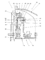
図1は、実施例のクラッチ装置を軸方向と直交する平面で切って見た断面図である。
クラッチ装置1は、図示しないエンジンと手動変速機であるトランスミッション10との間に設けられ、エンジンの出力軸とトランスミッション10のインプットシャフト11との間で駆動力の伝達、切断を行うものである。
Embodiments of a clutch device to which the present invention is applied will be described below.
The clutch device according to the embodiment is provided in an automobile such as a passenger car having a manual transmission with an internal combustion engine such as a gasoline engine or a diesel engine as a driving power source.
FIG. 1 is a cross-sectional view of the clutch device of the embodiment as seen along a plane orthogonal to the axial direction.
The
クラッチ装置1は、実質的にクラッチハウジング12の内部に収容されたフライホイール20、クラッチカバー30、クラッチディスク40、プレッシャープレート50、ダイアフラムスプリング60、レリーズベアリング70等を有して構成されている。
クラッチハウジング12は、トランスミッション10の変速機構部等を収容する筐体であるトランスミッションケースのエンジン側の端部に設けられ、エンジン側に開口した空間部を有する。
クラッチハウジング12の先端部は、図示しないエンジンのクランクケースに締結され固定される。
The
The
The tip of the
トランスミッション10へ駆動力を入力するインプットシャフト11は、エンジンの出力軸であるクランクシャフトと同心に配置されている。
インプットシャフト11のエンジン側の端部は、トランスミッションケースの内部から、クラッチハウジング12の内部へ突き出して配置されている。
インプットシャフト11の先端部における外周面部には、クラッチディスク40と係合するスプライン11aが形成されている。
An
The end of the
A
フライホイール20は、エンジンのクランクシャフトの端部に固定される円盤状の部材(回転質量体)である。
フライホイール20におけるトランスミッション10側の面部には、クラッチディスク40との摩擦面が形成されている。
フライホイール20の外周縁部には、図示しないスタータモータの駆動ギヤと係合する被駆動ギヤが形成されている。
The
A friction surface with the
A driven gear that engages with a drive gear of a starter motor (not shown) is formed on the outer peripheral edge of the
クラッチカバー30は、フライホイール20のトランスミッション10側に設けられ、フライホイール20と共働してクラッチディスク40等を収容する空間部を形成する円環状の部材である。
クラッチカバー30の外周縁部31は、フライホイール20にボルト31aによって締結されている。
The
The outer
クラッチカバー30は、外周縁部31からトランスミッション10側へ突き出して形成された円筒部32と、円筒部32のトランスミッション10側の端部から内径側へ延びたダイアフラムスプリング保持部33とを有する。
ダイアフラムスプリング保持部33は、フライホイール20の摩擦面と軸方向に間隔を隔てて配置され、クラッチディスク40、プレッシャープレート50、ダイアフラムスプリング60の外径側の領域は、これらの間に収容される。
ダイアフラムスプリング保持部33の中央部には、開口が形成されている。
これら外周縁部31、円筒部32、ダイアフラムスプリング保持部33は、一体に形成されている。
The
The diaphragm
An opening is formed in the center portion of the diaphragm
The outer
クラッチディスク40は、トランスミッション10のインプットシャフト11に取り付けられ、エンジン側からトランスミッション10側へトルクを伝達する円盤状の部材である。
クラッチディスク40は、インプットシャフト11に対して径方向につば状に張り出して形成されている。
クラッチディスク40は、金属製のプレート41の両面に、摩擦材(フェーシング)42を固定して構成されている。
これらの摩擦材42が設けられたクラッチディスク40の外径側の領域は、エンジンのクランクシャフトとともに回転するフライホイール20及びプレッシャープレート50によって挟持される。
The
The
The
The region on the outer diameter side of the
クラッチディスク40の内径側の領域には、スプライン係合部43、ダンパ44等が設けられている。
スプライン係合部43は、クラッチディスク40がインプットシャフト11に取り付けられる基部である。
スプライン係合部43は、トランスミッション10のインプットシャフト11が挿入され、スプライン11aと係合してトルク伝達を行うスプライン穴を有する。
スプライン係合部43は、インプットシャフト11に対して、軸方向に相対変位可能に支持されている。
ダンパ44は、プレート41及び摩擦材42と、スプライン係合部43との間の捩り振動を吸収する制振装置である。
A
The
The
The
The
プレッシャープレート50は、クラッチカバー30に対して軸方向に相対変位可能なよう支持された円盤状の部材であって、フライホイール20と協働してクラッチディスク40を挟持し、トルクを伝達するものである。
プレッシャープレート50の中央部には、クラッチディスク40のダンパ44等が収容される開口部が形成されている。
プレッシャープレート50のエンジン側の面部には、クラッチディスク40との摩擦面が形成されている。
また、プレッシャープレート50の摩擦面とは反対側の面部には、ダイアフラムスプリング60によって押圧される突起51が形成されている。
The
An opening for accommodating the
A friction surface with the
A
ダイアフラムスプリング60は、クラッチカバー30に対してプレッシャープレート50をクラッチディスク40側へ付勢して、クラッチディスク40の圧着力を発生させるバネ部材である。
ダイアフラムスプリング60は、例えばバネ鋼などの弾性を有する材料によって円盤状に形成されている。
ダイアフラムスプリング60の中央部には、インプットシャフト11等が挿入される開口が形成されている。
ダイアフラムスプリング60の外径側の領域は、クラッチカバー30のダイアフラムスプリング保持部33とプレッシャープレート50との間に配置されている。
ダイアフラムスプリング60の内周縁部は、クラッチディスク40のスプライン係合部43よりもトランスミッション10本体側において、レリーズベアリング70と係合している。
The
The
An opening into which the
A region on the outer diameter side of the
The inner peripheral edge portion of the
レリーズベアリング70は、ダイアフラムスプリング60の内周縁部に係合するとともに、図示しないクラッチペダルの踏込に連動して、ダイアフラムスプリング60の内周縁部をエンジンから遠ざかる方向に引き、プレッシャープレート50がクラッチディスク40を押圧する付勢力(クラッチ圧着力)を消失させ、クラッチ装置1を切断するものである。
The release bearing 70 engages with the inner peripheral edge of the
また、クラッチカバー30とプレッシャープレート50との間には、以下説明するトルクカム機構Tが設けられている。
トルクカム機構Tは、クラッチカバー30からプレッシャープレート50を介してクラッチディスク40へ伝達されるトルクに感応して、プレッシャープレート50をクラッチディスク40へ圧着させる推力を発生させるものである。
A torque cam mechanism T described below is provided between the
The torque cam mechanism T generates a thrust for pressing the
図2は、図1のII部矢視断面図であって、トルクカム機構Tをクラッチ装置1の回転軸に対する径方向から見た図である。
トルクカム機構Tは、クラッチカバー30の円筒部32の内周面におけるエンジン側の端部に形成されたカム34と、プレッシャープレート50の外周縁部におけるトランスミッション10側の端部に形成されたカムフォロワ52とを有して構成される。
FIG. 2 is a cross-sectional view taken along the line II in FIG. 1 and shows the torque cam mechanism T as viewed from the radial direction with respect to the rotation shaft of the
The torque cam mechanism T includes a
図2に示すように、カム34は、クラッチカバー30からプレッシャープレート50側へ、回転軸方向にほぼ沿って突出した突起として形成されている。
カム34をクラッチカバー30の径方向から見た形状は、先端側(プレッシャープレート50側)が窄まった台形状となっている。
カムフォロワ52は、カム34の形状に適合するよう、プレッシャープレート50の径方向から見たときに、プレッシャープレート50を台形状に凹ませた凹部として形成されている。
カムフォロワ52の内面と、カム34との表面とは、不可避的に設けられる隙間を隔てて対向するように形成されている。
プレッシャープレート50は、クラッチカバー30に対して、カム34とカムフォロワ52との周方向における隙間によって許容される範囲内で、中心軸回りに相対回転可能となっている。
エンジンからトランスミッション10への駆動トルクの伝達時に、カム34からカムフォロワ52へトルクを伝達する斜面が、周方向(図2における上下方向)に対してなす角度は、トルクカムによって得ることが必要な推力(クラッチディスクの圧着力)を考慮して設定される。
このようなトルクカム機構Tは、例えば、クラッチ装置1の周方向に分散して複数設けられる。
As shown in FIG. 2, the
The shape of the
The
The inner surface of the
The
When driving torque is transmitted from the engine to the
For example, a plurality of such torque cam mechanisms T are provided dispersed in the circumferential direction of the
また、クラッチカバー30とプレッシャープレート50との間には、プレッシャープレート50をクラッチカバー30側に(クラッチディスク40から離れる側に)付勢するリターンスプリングSが設けられている。
リターンスプリングSとして、例えばクラッチ装置1の回転軸方向に沿って配置され、両端部がクラッチカバー30及びプレッシャープレート50にそれぞれ連結された引張コイルバネを用いることができる。
実施例においては、リターンスプリングSの中間部は、ダイアフラムスプリング60に形成された開口内に挿入されている。
リターンスプリングSは、エンジントルクが例えばT0以下の低トルク領域において、トルクカム機構Tが発生する推力をキャンセルし、実質的に倍力効果が生じないようにするものである。
A return spring S is provided between the
As the return spring S, for example, a tension coil spring disposed along the rotation axis direction of the
In the embodiment, the intermediate portion of the return spring S is inserted into an opening formed in the
The return spring S cancels the thrust generated by the torque cam mechanism T in a low torque region where the engine torque is T0 or less, for example, so that the boosting effect is not substantially generated.
以下、上述した実施例の効果を、以下説明する本発明の比較例のクラッチ装置と対比して説明する。
比較例において、上述した実施例と実質的に共通する箇所については同じ符号を付して説明を省略し、主に相違点について説明する。
比較例のクラッチ装置は、トルクカム機構(カム34及びカムフォロワ52)を設けていない点を除き、実質的に実施例のクラッチ装置と同様の構成を有する。
Hereinafter, the effects of the above-described embodiment will be described in comparison with a clutch device of a comparative example of the present invention described below.
In the comparative example, portions that are substantially the same as those in the above-described embodiment are denoted by the same reference numerals, description thereof is omitted, and differences are mainly described.
The clutch device of the comparative example has substantially the same configuration as the clutch device of the embodiment except that the torque cam mechanism (
図3は、比較例のクラッチ装置におけるエンジントルクとクラッチ圧着力との相関を示すグラフである。
図3において、横軸はエンジントルクを示し、縦軸はクラッチプレートの圧着力を示している。また、図中において、トルク伝達に必要な圧着力を破線で示し、実際のクラッチ圧着力を実線で示している(図4において同じ)。
比較例においては、クラッチ圧着力は、ダイアフラムスプリング60のバネ力によってのみ得ている。
このため、クラッチ圧着力は、エンジントルクに関わらず一定値となる。
FIG. 3 is a graph showing the correlation between the engine torque and the clutch pressing force in the clutch device of the comparative example.
In FIG. 3, the horizontal axis indicates the engine torque, and the vertical axis indicates the pressing force of the clutch plate. In the drawing, the crimping force required for torque transmission is indicated by a broken line, and the actual clutch crimping force is indicated by a solid line (the same applies in FIG. 4).
In the comparative example, the clutch pressing force is obtained only by the spring force of the
For this reason, the clutch pressing force is a constant value regardless of the engine torque.
例えば、図3に示すクラッチ圧着力F1とした仕様においては、伝達可能なエンジントルクの上限はT1となり、最大エンジントルクがT2となる高出力仕様の場合には、ダイアフラムスプリング60のバネ定数を増加させて、クラッチ圧着力をF2とする必要がある。
しかし、このようにダイアフラムスプリング60を強化すると、クラッチペダルの踏力が大きくなって操作性が損なわれてしまう。
また、エンジンの仕様ごとに異なった仕様のダイアフラムスプリング60等を準備する必要が生じる。
For example, in the specification with the clutch pressing force F1 shown in FIG. 3, the upper limit of the transmittable engine torque is T1, and in the case of the high output specification where the maximum engine torque is T2, the spring constant of the
However, if the
Further, it is necessary to prepare a
図4は、実施例のクラッチ装置におけるエンジントルクとクラッチ圧着力との相関を示すグラフである。
実施例においては、エンジントルクがT0以上である中〜高トルク領域においては、トルクカム機構Tの推力により得られる倍力作用によって、クラッチ圧着力はエンジントルクの増大に応じて増加するため、エンジンの最大トルクがT1からT2に増加した場合であっても、ダイアフラムスプリング60のバネ定数を増加させる必要がない。
また、エンジントルクがT0以下であり、ダイアフラムスプリング60のみで十分なクラッチ圧着力が得られる低トルク領域においては、リターンスプリングSがトルクカム機構Tの倍力効果をキャンセルし、クラッチ圧着力は一定値(図4の場合にはF1)となる。
FIG. 4 is a graph showing the correlation between the engine torque and the clutch pressing force in the clutch device of the example.
In the embodiment, in the middle to high torque region where the engine torque is equal to or higher than T0, the clutch pressing force increases as the engine torque increases due to the boosting action obtained by the thrust of the torque cam mechanism T. Even when the maximum torque is increased from T1 to T2, it is not necessary to increase the spring constant of the
Further, in a low torque region where the engine torque is T0 or less and sufficient clutch pressing force can be obtained with only the
以上説明した実施例によれば、高エンジントルク仕様の車両であってもクラッチ操作力を軽減することが可能であり、車両の操作性、扱いやすさを向上することができる。
また、エンジントルクに応じた倍力効果が得られることから、最大トルクの仕様違いによってクラッチ装置の仕様を異ならせる必要がなく、部品の共通化を図ることができる。
また、クラッチ圧着力を倍力することによって、大径化や多板化をしなくても伝達トルク容量を増加させることが可能であり、他部品の配置に影響を与えることなく高出力化に対応することができる。
また、要求される伝達トルク容量が同等である場合には、クラッチ装置を小型化することができる。
さらに、リターンスプリングSによってエンジントルクがT0以下の低トルク領域ではトルクカム機構Tによる倍力効果をキャンセルしたことによって、発進時や空ぶかし時にトルクカム機構Tの推力によって意図しないクラッチ装置1の締結が生じることを防止でき、操作性をより一層向上することができる。
According to the embodiment described above, the clutch operating force can be reduced even in a vehicle with a high engine torque specification, and the operability and ease of handling of the vehicle can be improved.
Further, since a boosting effect according to the engine torque can be obtained, it is not necessary to make the specifications of the clutch device different depending on the specification of the maximum torque, and the parts can be shared.
In addition, by boosting the clutch pressing force, it is possible to increase the transmission torque capacity without increasing the diameter or increasing the number of plates, resulting in higher output without affecting the arrangement of other parts. Can respond.
Further, when the required transmission torque capacity is equal, the clutch device can be reduced in size.
Further, in the low torque region where the engine torque is equal to or lower than T0 by the return spring S, the boosting effect by the torque cam mechanism T is canceled, so that the
(変形例)
本発明は、以上説明した実施例に限定されることなく、種々の変形や変更が可能であって、それらも本発明の技術的範囲内である。
クラッチ装置の構成は上述した実施例の構成に限らず、適宜変更することが可能である。
例えば、トルクカム機構の形状やカムプロファイルは実施例の構成に限らず、適宜変更することができる。
また、実施例では、エンジンからトランスミッションへの駆動トルク、及び、トランスミッションからエンジン側へのバックトルクの両方に応じて倍力効果が得られるようにしているが、少なくとも駆動トルク側でのみ倍力効果が得られる設定としてもよい。
また、レリーズベアリングは実施例のようなプル式に限らずプッシュ式であってもよく、クラッチプレートの枚数なども特に限定されない。
また、本発明は、ドライバが脚力でクラッチ操作を行う手動変速機のクラッチ装置に限らず、アクチュエータによってクラッチ操作が行われる手動変速機ベースの自動変速機(AMT)やダブルクラッチトランスミッション(DCT)などのクラッチ装置にも適用することが可能である。この場合、アクチュエータの小容量化などが可能となる。
(Modification)
The present invention is not limited to the embodiments described above, and various modifications and changes are possible, and these are also within the technical scope of the present invention.
The configuration of the clutch device is not limited to the configuration of the embodiment described above, and can be changed as appropriate.
For example, the shape and cam profile of the torque cam mechanism are not limited to the configuration of the embodiment, and can be changed as appropriate.
In the embodiment, the boosting effect is obtained according to both the driving torque from the engine to the transmission and the back torque from the transmission to the engine side. However, the boosting effect is at least only on the driving torque side. May be set to obtain
The release bearing is not limited to the pull type as in the embodiment, and may be a push type, and the number of clutch plates is not particularly limited.
Further, the present invention is not limited to a clutch device of a manual transmission in which a driver performs clutch operation with leg force, but a manual transmission-based automatic transmission (AMT) or a double clutch transmission (DCT) in which a clutch operation is performed by an actuator. The present invention can also be applied to other clutch devices. In this case, the capacity of the actuator can be reduced.
1 クラッチ装置 10 トランスミッション
11 インプットシャフト 11a スプライン
12 クラッチハウジング 20 フライホイール
30 クラッチカバー 31 外周縁部
31a ボルト 32 円筒部
33 ダイアフラムスプリング保持部 34 カム
40 クラッチディスク 41 プレート
42 摩擦材 43 スプライン係合部
44 ダンパ 50 プレッシャープレート
51 突起 52 カムフォロワ
60 ダイアフラムスプリング 70 レリーズベアリング
T トルクカム機構 S リターンスプリング
DESCRIPTION OF
Claims (2)
前記フライホイールにおける前記エンジンの反対側に固定されるクラッチカバーと、
前記フライホイールに対向しかつ前記クラッチカバーに対して軸方向に相対変位可能に支持されるプレッシャープレートと、
前記プレッシャープレートを前記クラッチカバー側へ付勢するダイアフラムスプリングと、
変速機の入力軸に取り付けられ前記フライホイールと前記プレッシャープレートとの間で挟持されるクラッチディスクと、
前記プレッシャープレート及び前記クラッチカバーの一方に設けられたカム及び他方に設けられたカムフォロワを有し、前記プレッシャープレートが伝達するトルクに感応して前記プレッシャープレートを前記クラッチディスク側へ押圧するトルクカム機構と
を備えることを特徴とするクラッチ装置。 A flywheel that is rotationally driven by the output shaft of the engine;
A clutch cover fixed to the opposite side of the engine in the flywheel;
A pressure plate opposed to the flywheel and supported so as to be relatively displaceable in the axial direction with respect to the clutch cover;
A diaphragm spring for urging the pressure plate toward the clutch cover;
A clutch disk attached to the input shaft of the transmission and sandwiched between the flywheel and the pressure plate;
A torque cam mechanism having a cam provided on one of the pressure plate and the clutch cover and a cam follower provided on the other, and pressing the pressure plate toward the clutch disk in response to torque transmitted by the pressure plate; A clutch device comprising:
を特徴とする請求項1に記載のクラッチ装置。 The clutch device according to claim 1, further comprising a return spring that biases the pressure plate toward the clutch cover.
Priority Applications (1)
| Application Number | Priority Date | Filing Date | Title |
|---|---|---|---|
| JP2014065226A JP2015187476A (en) | 2014-03-27 | 2014-03-27 | clutch device |
Applications Claiming Priority (1)
| Application Number | Priority Date | Filing Date | Title |
|---|---|---|---|
| JP2014065226A JP2015187476A (en) | 2014-03-27 | 2014-03-27 | clutch device |
Publications (1)
| Publication Number | Publication Date |
|---|---|
| JP2015187476A true JP2015187476A (en) | 2015-10-29 |
Family
ID=54429795
Family Applications (1)
| Application Number | Title | Priority Date | Filing Date |
|---|---|---|---|
| JP2014065226A Pending JP2015187476A (en) | 2014-03-27 | 2014-03-27 | clutch device |
Country Status (1)
| Country | Link |
|---|---|
| JP (1) | JP2015187476A (en) |
Cited By (2)
| Publication number | Priority date | Publication date | Assignee | Title |
|---|---|---|---|---|
| CN108775347A (en) * | 2018-05-25 | 2018-11-09 | 广东机电职业技术学院 | A kind of combined clutch |
| WO2022064635A1 (en) * | 2020-09-25 | 2022-03-31 | 有限会社T.P.P. | Pressure plate device for friction clutch |
-
2014
- 2014-03-27 JP JP2014065226A patent/JP2015187476A/en active Pending
Cited By (6)
| Publication number | Priority date | Publication date | Assignee | Title |
|---|---|---|---|---|
| CN108775347A (en) * | 2018-05-25 | 2018-11-09 | 广东机电职业技术学院 | A kind of combined clutch |
| CN108775347B (en) * | 2018-05-25 | 2024-01-09 | 广东机电职业技术学院 | Combined clutch |
| WO2022064635A1 (en) * | 2020-09-25 | 2022-03-31 | 有限会社T.P.P. | Pressure plate device for friction clutch |
| JPWO2022064635A1 (en) * | 2020-09-25 | 2022-03-31 | ||
| JP7161625B2 (en) | 2020-09-25 | 2022-10-26 | 有限会社T.P.P. | Friction clutch pressure plate device |
| US11655861B2 (en) | 2020-09-25 | 2023-05-23 | T.P.P. Co. | Friction clutch pressure plate device |
Similar Documents
| Publication | Publication Date | Title |
|---|---|---|
| US6722483B2 (en) | Twin clutch | |
| US7993206B2 (en) | Torque fluctuation absorber | |
| US9267569B2 (en) | Planetary torsional damper system | |
| JP2017510769A (en) | Pulley assembly with radial orientation decoupling mechanism | |
| JP2011033106A (en) | Multi-disc clutch | |
| US20230115866A1 (en) | Torsional vibration damper having an axis of rotation for a drive train | |
| JP6394406B2 (en) | Damper device | |
| JP2019518919A (en) | Centrifugal clutch and powertrain with coupling pin with minimal friction | |
| EP2829767B1 (en) | Torsional vibration damping device | |
| JP2009115262A (en) | Flywheel | |
| US20040118655A1 (en) | Torque transmission arrangement | |
| JP2015187476A (en) | clutch device | |
| KR101073807B1 (en) | Torsional vibration damper of flywheel | |
| JP2004324748A (en) | Clutch device | |
| CN115217903B (en) | Flywheel device and power system | |
| JP2012163139A (en) | Clutch device | |
| JP4434660B2 (en) | 2 mass flywheel | |
| JPWO2012046273A1 (en) | Torsional vibration damping device | |
| CN113905918A (en) | Clutch assembly | |
| JP2005061488A5 (en) | ||
| JP2013061032A (en) | Clutch device | |
| JP3977211B2 (en) | Clutch device | |
| KR100534850B1 (en) | Clutch disc for reducing rattle noise | |
| US20110100776A1 (en) | Friction clutch system | |
| US7401687B2 (en) | Dual clutch engine coupling damper |