JP2015111530A - Microcapsule for nonaqueous electrolyte secondary batteries, separator for nonaqueous electrolyte secondary batteries, electrode for nonaqueous electrolyte secondary batteries, electrode active material layer for nonaqueous electrolyte secondary batteries, and nonaqueous electrolyte secondary battery - Google Patents
Microcapsule for nonaqueous electrolyte secondary batteries, separator for nonaqueous electrolyte secondary batteries, electrode for nonaqueous electrolyte secondary batteries, electrode active material layer for nonaqueous electrolyte secondary batteries, and nonaqueous electrolyte secondary battery Download PDFInfo
- Publication number
- JP2015111530A JP2015111530A JP2013253565A JP2013253565A JP2015111530A JP 2015111530 A JP2015111530 A JP 2015111530A JP 2013253565 A JP2013253565 A JP 2013253565A JP 2013253565 A JP2013253565 A JP 2013253565A JP 2015111530 A JP2015111530 A JP 2015111530A
- Authority
- JP
- Japan
- Prior art keywords
- electrolyte secondary
- secondary battery
- microcapsule
- nonaqueous electrolyte
- active material
- Prior art date
- Legal status (The legal status is an assumption and is not a legal conclusion. Google has not performed a legal analysis and makes no representation as to the accuracy of the status listed.)
- Granted
Links
Images


Classifications
-
- H—ELECTRICITY
- H01—ELECTRIC ELEMENTS
- H01M—PROCESSES OR MEANS, e.g. BATTERIES, FOR THE DIRECT CONVERSION OF CHEMICAL ENERGY INTO ELECTRICAL ENERGY
- H01M50/00—Constructional details or processes of manufacture of the non-active parts of electrochemical cells other than fuel cells, e.g. hybrid cells
- H01M50/40—Separators; Membranes; Diaphragms; Spacing elements inside cells
- H01M50/409—Separators, membranes or diaphragms characterised by the material
- H01M50/411—Organic material
- H01M50/414—Synthetic resins, e.g. thermoplastics or thermosetting resins
-
- H—ELECTRICITY
- H01—ELECTRIC ELEMENTS
- H01M—PROCESSES OR MEANS, e.g. BATTERIES, FOR THE DIRECT CONVERSION OF CHEMICAL ENERGY INTO ELECTRICAL ENERGY
- H01M10/00—Secondary cells; Manufacture thereof
- H01M10/05—Accumulators with non-aqueous electrolyte
- H01M10/052—Li-accumulators
-
- H—ELECTRICITY
- H01—ELECTRIC ELEMENTS
- H01M—PROCESSES OR MEANS, e.g. BATTERIES, FOR THE DIRECT CONVERSION OF CHEMICAL ENERGY INTO ELECTRICAL ENERGY
- H01M4/00—Electrodes
- H01M4/02—Electrodes composed of, or comprising, active material
- H01M4/13—Electrodes for accumulators with non-aqueous electrolyte, e.g. for lithium-accumulators; Processes of manufacture thereof
-
- H—ELECTRICITY
- H01—ELECTRIC ELEMENTS
- H01M—PROCESSES OR MEANS, e.g. BATTERIES, FOR THE DIRECT CONVERSION OF CHEMICAL ENERGY INTO ELECTRICAL ENERGY
- H01M50/00—Constructional details or processes of manufacture of the non-active parts of electrochemical cells other than fuel cells, e.g. hybrid cells
- H01M50/40—Separators; Membranes; Diaphragms; Spacing elements inside cells
- H01M50/409—Separators, membranes or diaphragms characterised by the material
- H01M50/443—Particulate material
-
- H—ELECTRICITY
- H01—ELECTRIC ELEMENTS
- H01M—PROCESSES OR MEANS, e.g. BATTERIES, FOR THE DIRECT CONVERSION OF CHEMICAL ENERGY INTO ELECTRICAL ENERGY
- H01M50/00—Constructional details or processes of manufacture of the non-active parts of electrochemical cells other than fuel cells, e.g. hybrid cells
- H01M50/40—Separators; Membranes; Diaphragms; Spacing elements inside cells
- H01M50/409—Separators, membranes or diaphragms characterised by the material
- H01M50/449—Separators, membranes or diaphragms characterised by the material having a layered structure
-
- H—ELECTRICITY
- H01—ELECTRIC ELEMENTS
- H01M—PROCESSES OR MEANS, e.g. BATTERIES, FOR THE DIRECT CONVERSION OF CHEMICAL ENERGY INTO ELECTRICAL ENERGY
- H01M50/00—Constructional details or processes of manufacture of the non-active parts of electrochemical cells other than fuel cells, e.g. hybrid cells
- H01M50/40—Separators; Membranes; Diaphragms; Spacing elements inside cells
- H01M50/489—Separators, membranes, diaphragms or spacing elements inside the cells, characterised by their physical properties, e.g. swelling degree, hydrophilicity or shut down properties
-
- Y—GENERAL TAGGING OF NEW TECHNOLOGICAL DEVELOPMENTS; GENERAL TAGGING OF CROSS-SECTIONAL TECHNOLOGIES SPANNING OVER SEVERAL SECTIONS OF THE IPC; TECHNICAL SUBJECTS COVERED BY FORMER USPC CROSS-REFERENCE ART COLLECTIONS [XRACs] AND DIGESTS
- Y02—TECHNOLOGIES OR APPLICATIONS FOR MITIGATION OR ADAPTATION AGAINST CLIMATE CHANGE
- Y02E—REDUCTION OF GREENHOUSE GAS [GHG] EMISSIONS, RELATED TO ENERGY GENERATION, TRANSMISSION OR DISTRIBUTION
- Y02E60/00—Enabling technologies; Technologies with a potential or indirect contribution to GHG emissions mitigation
- Y02E60/10—Energy storage using batteries
Landscapes
- Chemical & Material Sciences (AREA)
- Chemical Kinetics & Catalysis (AREA)
- Electrochemistry (AREA)
- General Chemical & Material Sciences (AREA)
- Engineering & Computer Science (AREA)
- Materials Engineering (AREA)
- Manufacturing & Machinery (AREA)
- Battery Electrode And Active Subsutance (AREA)
- Cell Separators (AREA)
Abstract
Description
本発明は、非水電解質二次電池用マイクロカプセル、非水電解質二次電池用セパレータ、非水電解質二次電池用電極、非水電解質二次電池用電極活物質層、及び非水電解質二次電池に関する。 The present invention relates to a microcapsule for a non-aqueous electrolyte secondary battery, a separator for a non-aqueous electrolyte secondary battery, an electrode for a non-aqueous electrolyte secondary battery, an electrode active material layer for a non-aqueous electrolyte secondary battery, and a non-aqueous electrolyte secondary It relates to batteries.
例えば特許文献1に開示されるように、耐熱性の有機繊維を用いた不織布に、熱膨張することが可能な熱膨張性マイクロカプセルを含有させることによって、内部短絡等による急激な発熱反応が起こった場合でも、セパレータの絶縁性が消失するのを抑止できる非水系二次電池を提供できることが知られている。熱膨性マイクロカプセルは、ポリスチレンやポリオレフィン(ポリエチレンやポリプロピレン等)(Polystyrene and polyolefin (polyethylene or polypropylene))で作製されることが多い。 For example, as disclosed in Patent Document 1, a sudden exothermic reaction due to an internal short circuit occurs by incorporating a thermally expandable microcapsule capable of thermally expanding into a nonwoven fabric using heat-resistant organic fibers. Even in such a case, it is known that a non-aqueous secondary battery that can suppress the loss of the insulating properties of the separator can be provided. Thermally expansible microcapsules are often made of polystyrene or polyolefin (polyethylene or polypropylene, etc.) (Polystyrene and polypropylene (polyethylene or polypropylene)).
しかしながら、従来の熱膨張性マイクロカプセルは粒子径が大きいという問題があった。このため、熱膨張性マイクロカプセルを電極又はセパレータ上に配したリチウムイオン(lithium ion)二次電池は、膜厚が増加するという問題があった。 However, the conventional thermally expandable microcapsules have a problem that the particle diameter is large. For this reason, the lithium ion secondary battery in which the thermally expandable microcapsules are arranged on the electrode or the separator has a problem that the film thickness increases.
さらに、ポリスチレン製の熱膨張性マイクロカプセルは電解液に溶解しやすいため、電池用途への適用が困難であった。一方、ポリエチレンやポリプロピレン等のポリオレフィンは耐電解液性の観点では問題ないが、発泡剤とポリオレフィンを溶融混練後、押し出し成型によって作製されるため、サブミクロン(Sub−micron)以下の微粒子を作製することが難しいという問題があった。 Furthermore, since the polystyrene-based thermally expandable microcapsules are easily dissolved in the electrolytic solution, it has been difficult to apply to battery applications. On the other hand, polyolefins such as polyethylene and polypropylene have no problem in terms of resistance to electrolytic solution, but are produced by extrusion molding after melt-kneading a foaming agent and polyolefin, so that sub-micron or smaller particles are produced. There was a problem that it was difficult.
そこで、本発明は、上記問題に鑑みてなされたものであり、本発明の目的とするところは、非水電解質二次電池を薄膜化し、非水電解質二次電池内で安定して存在し、かつ、非水電解質二次電池の異常発熱時に電極間の絶縁を確保することが可能な、新規かつ改良された非水電解質二次電池用マイクロカプセル、非水電解質二次電池用セパレータ、非水電解質二次電池用電極、非水電解質二次電池用電極活物質層、及び非水電解質二次電池を提供することにある。 Therefore, the present invention has been made in view of the above problems, and the object of the present invention is to make the nonaqueous electrolyte secondary battery into a thin film and stably exist in the nonaqueous electrolyte secondary battery. In addition, a novel and improved non-aqueous electrolyte secondary battery microcapsule, non-aqueous electrolyte secondary battery separator, non-water that can ensure insulation between electrodes in the event of abnormal heat generation of the non-aqueous electrolyte secondary battery The object is to provide an electrode for an electrolyte secondary battery, an electrode active material layer for a non-aqueous electrolyte secondary battery, and a non-aqueous electrolyte secondary battery.
上記課題を解決するために、本発明のある観点によれば、発泡性モノマー(monomer)の重合体を含むコア(core)部と、コア部を覆い、かつ、非水電解質二次電池内での安定性がコア部よりも高いシェル(shell)部と、を有し、平均粒子径が0.05μm〜0.5μmであることを特徴とする、非水電解質二次電池用マイクロカプセルが提供される。 In order to solve the above problems, according to an aspect of the present invention, a core part including a polymer of a foamable monomer (monomer), a core part covering the core part, and a non-aqueous electrolyte secondary battery A microcapsule for a non-aqueous electrolyte secondary battery, characterized in that it has a shell portion whose stability is higher than that of the core portion and has an average particle diameter of 0.05 μm to 0.5 μm Is done.
本観点のマイクロカプセルは、非水電解質二次電池内で安定して存在し、かつ異常発熱時に発砲(膨張)する。また、マイクロカプセルの平均粒子径は0.05μm〜0.5μmと非常に小径である。 The microcapsules of this aspect are stably present in the non-aqueous electrolyte secondary battery and fire (expand) when abnormal heat is generated. In addition, the average particle size of the microcapsules is as small as 0.05 μm to 0.5 μm.
したがって、マイクロカプセルは、非水電解質二次電池を薄膜化し、非水電解質二次電池内で安定して存在し、かつ、非水電解質二次電池の異常発熱時に電極間の絶縁を確保することができる。さらに、マイクロカプセルは、非水電解質二次電池の異常発熱時にセパレータの熱収縮を抑制することができる。 Therefore, the microcapsule makes the non-aqueous electrolyte secondary battery thin, stably exists in the non-aqueous electrolyte secondary battery, and ensures insulation between the electrodes when the non-aqueous electrolyte secondary battery is abnormally heated. Can do. Further, the microcapsule can suppress the thermal contraction of the separator when the nonaqueous electrolyte secondary battery is abnormally heated.
ここで、発泡性モノマーはジアゾ(Diazo compound)化合物を含んでいてもよく、この場合、異常発熱時に迅速に発泡することができる。 Here, the foamable monomer may contain a diazo compound, and in this case, the foamable monomer can be rapidly foamed during abnormal heat generation.
また、ジアゾ化合物は、以下の化学式Iで示される構造を有していてもよく、この場合、非水電解質二次電池の異常発熱時に迅速に発泡することができる。 Further, the diazo compound may have a structure represented by the following chemical formula I. In this case, the diazo compound can rapidly foam when the nonaqueous electrolyte secondary battery generates abnormal heat.
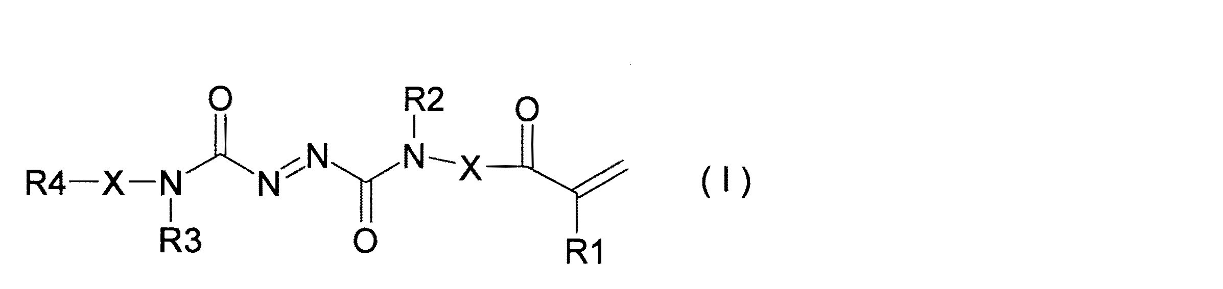
化学式I中、R1は水素原子又はメチル(methyl)基、R2は水素又は炭素数1〜6のアルキル(alkyl)基、R3は水素又は炭素数1〜6のアルキル基、R4は水素、メチル基、アクリル(acrylic)基、メタクリル(methacrylic)基、またはグリシジル(Glycidyl)基、Xは直結又は炭素数1〜6のアルキレン基を表す。 In the chemical formula I, R1 is a hydrogen atom or a methyl group, R2 is hydrogen or an alkyl group having 1 to 6 carbon atoms, R3 is hydrogen or an alkyl group having 1 to 6 carbon atoms, R4 is hydrogen or a methyl group , An acrylic group, a methacrylic group, or a glycidyl group, X represents a direct bond or an alkylene group having 1 to 6 carbon atoms.
また、ジアゾ化合物は、以下の化学式IIで示される構造を有していてもよく、この場合、非水電解質二次電池の異常発熱時に迅速に発泡することができる。 Further, the diazo compound may have a structure represented by the following chemical formula II, and in this case, the diazo compound can be quickly foamed during abnormal heat generation of the non-aqueous electrolyte secondary battery.
化学式II中、R1は水素原子又はメチル基、R2は水素又は炭素数1〜6のアルキル基、Aはメチレン(methylene)基又はカルボニル(carbonyl)基、Qはメチレン基又はメチン(methine)基、Tは直結、二重結合、メチレン基、酸素、またはNH基を表す。 In Formula II, R1 is a hydrogen atom or a methyl group, R2 is hydrogen or an alkyl group having 1 to 6 carbon atoms, A is a methylene group or a carbonyl group, Q is a methylene group or a methine group, T represents a direct bond, a double bond, a methylene group, oxygen, or an NH group.
また、発泡温度が120℃以上250℃以下であってもよく、この場合、非水電解質二次電池の異常発熱時により確実に発泡することができる。 Further, the foaming temperature may be 120 ° C. or more and 250 ° C. or less, and in this case, foaming can be performed more reliably when the nonaqueous electrolyte secondary battery is abnormally heated.
本発明の他の観点によれば、セパレータと、セパレータ上に設けられ、上記の非水電解質二次電池用マイクロカプセルが分散したマイクロカプセル層と、を有することを特徴とする、非水電解質二次電池用セパレータ層が提供される。 According to another aspect of the present invention, there is provided a nonaqueous electrolyte two comprising a separator, and a microcapsule layer provided on the separator and in which the microcapsules for the nonaqueous electrolyte secondary battery are dispersed. A separator layer for a secondary battery is provided.
この観点によるセパレータ層を非水電解質二次電池に適用することで、非水電解質二次電池を薄膜化し、かつ、非水電解質二次電池の異常発熱時に電極間の絶縁を確保することができる。さらに、マイクロカプセルは、非水電解質二次電池内で安定して存在し、非水電解質二次電池の異常発熱時にセパレータの熱収縮を抑制することができる。 By applying the separator layer according to this viewpoint to the non-aqueous electrolyte secondary battery, the non-aqueous electrolyte secondary battery can be thinned and insulation between the electrodes can be ensured at the time of abnormal heat generation of the non-aqueous electrolyte secondary battery. . Furthermore, the microcapsule exists stably in the nonaqueous electrolyte secondary battery, and can suppress thermal contraction of the separator when the nonaqueous electrolyte secondary battery generates abnormal heat.
本発明の他の観点によれば、電極活物質層と、電極活物質層上に設けられ、上記の非水電解質二次電池用マイクロカプセルが分散したマイクロカプセル層と、を有することを特徴とする、非水電解質二次電池用電極が提供される。 According to another aspect of the present invention, there is provided an electrode active material layer, and a microcapsule layer provided on the electrode active material layer, in which the microcapsules for the nonaqueous electrolyte secondary battery are dispersed. An electrode for a non-aqueous electrolyte secondary battery is provided.
この観点による電極を非水電解質二次電池に適用することで、非水電解質二次電池を薄膜化し、かつ、非水電解質二次電池の異常発熱時に電極間の絶縁を確保することができる。さらに、マイクロカプセルは、非水電解質二次電池内で安定して存在し、非水電解質二次電池の異常発熱時にセパレータの熱収縮を抑制することができる。 By applying the electrode according to this viewpoint to the non-aqueous electrolyte secondary battery, the non-aqueous electrolyte secondary battery can be thinned, and insulation between the electrodes can be ensured when the non-aqueous electrolyte secondary battery is abnormally heated. Furthermore, the microcapsule exists stably in the nonaqueous electrolyte secondary battery, and can suppress thermal contraction of the separator when the nonaqueous electrolyte secondary battery generates abnormal heat.
本発明の他の観点によれば、電極活物質と、上記の非水電解質二次電池用マイクロカプセルと、を有することを特徴とする、非水電解質二次電池用電極活物質層が提供される。 According to another aspect of the present invention, there is provided an electrode active material layer for a non-aqueous electrolyte secondary battery, comprising an electrode active material and the microcapsules for a non-aqueous electrolyte secondary battery. The
この観点による活物質層を非水電解質二次電池に適用することで、非水電解質二次電池を薄膜化し、かつ、非水電解質二次電池の異常発熱時に電極間の絶縁を確保することができる。さらに、マイクロカプセルは、非水電解質二次電池内で安定して存在し、非水電解質二次電池の異常発熱時にセパレータの熱収縮を抑制することができる。 By applying the active material layer according to this viewpoint to the non-aqueous electrolyte secondary battery, it is possible to reduce the thickness of the non-aqueous electrolyte secondary battery and ensure insulation between the electrodes when the non-aqueous electrolyte secondary battery generates abnormal heat. it can. Furthermore, the microcapsule exists stably in the nonaqueous electrolyte secondary battery, and can suppress thermal contraction of the separator when the nonaqueous electrolyte secondary battery generates abnormal heat.
本発明の他の観点によれば、上記の非水電解質二次電池用セパレータ、上記の非水電解質二次電池用電極、及び上記の非水電解質二次電池用電極活物質層のうち、すくなくとも1つを含むことを特徴とする、非水電解質二次電池が提供される。 According to another aspect of the present invention, at least one of the separator for a non-aqueous electrolyte secondary battery, the electrode for the non-aqueous electrolyte secondary battery, and the electrode active material layer for the non-aqueous electrolyte secondary battery. There is provided a non-aqueous electrolyte secondary battery comprising one.
この観点による非水電解質二次電池は、薄膜化が可能であり、かつ、異常発熱時に電極間の絶縁を確保することができる。さらに、マイクロカプセルは、非水電解質二次電池内で安定して存在し、非水電解質二次電池の異常発熱時にセパレータの熱収縮を抑制することができる。 The non-aqueous electrolyte secondary battery according to this viewpoint can be thinned and can ensure insulation between the electrodes during abnormal heat generation. Furthermore, the microcapsule exists stably in the nonaqueous electrolyte secondary battery, and can suppress thermal contraction of the separator when the nonaqueous electrolyte secondary battery generates abnormal heat.
以上説明したように本発明によるマイクロカプセルは、非水電解質二次電池を薄膜化し、非水電解質二次電池内で安定して存在し、かつ、非水電解質二次電池の異常発熱時に電極間の絶縁を確保することができる。 As described above, the microcapsule according to the present invention has a non-aqueous electrolyte secondary battery made into a thin film, stably present in the non-aqueous electrolyte secondary battery, and between the electrodes during abnormal heat generation of the non-aqueous electrolyte secondary battery. Insulation can be ensured.
以下に添付図面を参照しながら、本発明の好適な実施の形態について詳細に説明する。なお、本明細書及び図面において、実質的に同一の機能構成を有する構成要素については、同一の符号を付することにより重複説明を省略する。 Exemplary embodiments of the present invention will be described below in detail with reference to the accompanying drawings. In addition, in this specification and drawing, about the component which has the substantially same function structure, duplication description is abbreviate | omitted by attaching | subjecting the same code | symbol.
(第1の実施形態)
(リチウムイオン二次電池の構成)
まず、図1に基づいて、第1の実施形態に係るリチウムイオン二次電池10の構成について説明する。
(First embodiment)
(Configuration of lithium ion secondary battery)
First, based on FIG. 1, the structure of the lithium ion
リチウムイオン二次電池10は、正極20と、負極30と、セパレータ層40とを備える。リチウムイオン二次電池10の充電到達電圧(酸化還元電位)は、例えば4.3V(vs.Li/Li+)以上5.0V以下、特に4.5V以上5.0V以下となる。リチウムイオン二次電池10の形態は、特に限定されない。即ち、リチウムイオン二次電池10は、円筒形、角形、ラミネート(laminate)形、ボタン(button)形等のいずれであってもよい。
The lithium ion
正極20は、集電体21と、正極活物質層22とを備える。集電体21は、導電体であればどのようなものでも良く、例えば、アルミニウム(aluminium)、ステンレス(stainless)鋼、及びニッケルメッキ(nickel coated)鋼等で構成される。
The
正極活物質層22は、少なくとも正極活物質を含み、導電剤と、結着剤とをさらに含んでいてもよい。正極活物質は、例えばリチウムを含む固溶体酸化物であるが、電気化学的にリチウムイオンを吸蔵及び放出することができる物質であれば特に制限されない。固溶体酸化物は、例えば、LiaMnxCoyNizO2(1.150≦a≦1.430、0.45≦x≦0.6、0.10≦y≦0.15、0.20≦z≦0.28)、LiMnxCoyNizO2(0.3≦x≦0.85、0.10≦y≦0.3、0.10≦z≦0.3)、LiMn1.5Ni0.5O4となる。
The positive electrode
導電剤は、例えばケッチェンブラック(Ketjenblack)、アセチレンブラック(acetylene black)等のカーボンブラック、天然黒鉛、人造黒鉛等であるが、正極の導電性を高めるためのものであれば特に制限されない。 The conductive agent is, for example, carbon black such as ketjen black or acetylene black, natural graphite, artificial graphite, or the like, but is not particularly limited as long as it is intended to increase the conductivity of the positive electrode.
結着剤は、例えばポリフッ化ビニリデン(polyvinylidene fluoride)、エチレンプロピレンジエン(ethylene−propylene−diene)三元共重合体、スチレンブタジエンゴム(Styrene−butadiene rubber)、アクリロニトリルブタジエンゴム(acrylonitrile−butadiene rubber)、フッ素ゴム(fluororubber)、ポリ酢酸ビニル(polyvinyl acetate)、ポリメチルメタクリレート(polymethylmethacrylate)、ポリエチレン(polyethylene)、ニトロセルロース(cellulose nitrate)等であるが、正極活物質及び導電剤を集電体21上に結着させることができるものであれば、特に制限されない。
Examples of the binder include polyvinylidene fluoride, ethylene-propylene-diene terpolymer, styrene-butadiene rubber, acrylonitrile butadiene rubber, and acrylonitrile butadiene rubber. Fluororubber, polyvinyl acetate, polymethylmethacrylate, polyethylene, nitrocellulose, and the like, and a positive electrode active material and a conductive agent on the
正極活物質層22は、例えば、以下の製法により作製される。すなわち、まず、正極活物質、導電剤、及び結着剤を乾式混合することで正極合剤を作製する。ついで、正極合剤を適当な有機溶媒に分散させることで正極合剤スラリー(slurry)を形成し、この正極合剤スラリーを集電体21上に塗工し、乾燥、圧延することで正極活物質層が形成される。
The positive electrode
負極30は、集電体31と、負極活物質層32とを含む。集電体31は、導電体であればどのようなものでも良く、例えば、アルミニウム、ステンレス鋼、及びニッケルメッキ鋼等で構成される。負極活物質層32は、リチウムイオン二次電池の負極活物質層として使用されるものであれば、どのようなものであってもよい。例えば、負極活物質層32は、負極活物質を含み、結着剤をさらに含んでいてもよい。負極活物質は、例えば、黒鉛活物質(人造黒鉛、天然黒鉛、人造黒鉛と天然黒鉛との混合物、人造黒鉛を被覆した天然黒鉛等)、ケイ素もしくはスズもしくはそれらの酸化物の微粒子と黒鉛活物質との混合物、ケイ素もしくはスズの微粒子、ケイ素もしくはスズを基本材料とした合金、及びLi4Ti5O12等の酸化チタン系化合物等が考えられる。ケイ素の酸化物は、SiOx(0≦x≦2)で表される。負極活物質としては、これらの他に、例えば金属リチウム等が挙げられる。結着剤は、正極活物質層22を構成する結着剤と同様のものでもある。正極活物質と結着剤との質量比は特に制限されず、従来のリチウムイオン二次電池で採用される質量比が本実施形態でも適用可能である。
The
負極活物質層32は、例えば、以下の製法により作製される。すなわち、まず、負極活物質、及び結着剤を乾式混合することで負極合剤を作製する。ついで、負極合剤を適当な溶媒に分散させることで負極合剤スラリー(slurry)を形成し、この負極合剤スラリーを集電体31上に塗工し、乾燥、圧延することで負極活物質層32が形成される。
The negative electrode
セパレータ層40は、セパレータ(separator)40aと、マイクロカプセル層40b、40cと、非水電解液とを含む。セパレータは、特に制限されず、リチウムイオン二次電池のセパレータとして使用されるものであれば、どのようなものであってもよい。セパレータとしては、優れた高率放電性能を示す多孔膜や不織布等を、単独あるいは併用することが好ましい。セパレータを構成する樹脂としては、例えばポリエチレン(polyethylene),ポリプロピレン(polypropylene)等に代表されるポリオレフィン(polyolefin)系樹脂、ポリエチレンテレフタレート(Polyethylene terephthalate),ポリブチレンテレフタレート(polybutylene terephthalate)等に代表されるポリエステル(Polyester)系樹脂、PVDF、フッ化ビニリデン(VDF)−ヘキサフルオロプロピレン(HFP)共重合体、フッ化ビニリデン−パーフルオロビニルエーテル(par fluorovinyl ether)共重合体、フッ化ビニリデン−テトラフルオロエチレン(tetrafluoroethylene)共重合体、フッ化ビニリデン−トリフルオロエチレン(trifluoroethylene)共重合体、フッ化ビニリデン−フルオロエチレン(fluoroethylene)共重合体、フッ化ビニリデン−ヘキサフルオロアセトン(hexafluoroacetone)共重合体、フッ化ビニリデン−エチレン(ethylene)共重合体、フッ化ビニリデン−プロピレン(propylene)共重合体、フッ化ビニリデン−トリフルオロプロピレン(trifluoro propylene)共重合体、フッ化ビニリデン−テトラフルオロエチレン(tetrafluoroethylene)−ヘキサフルオロプロピレン(hexafluoropropylene)共重合体、フッ化ビニリデン−エチレン(ethylene)−テトラフルオロエチレン(tetrafluoroethylene)共重合体等を挙げることができる。
The
マイクロカプセル層40bは、セパレータ40aの表面のうち、正極活物質層22に対向する面上に形成される。マイクロカプセル層40cは、セパレータ40aの表面のうち、負極活物質層32に対向する面上に形成される。マイクロカプセル層40b、40cは、マイクロカプセルと、結着剤とを含む。
The
マイクロカプセルは、コアシェル型の熱膨張性マイクロカプセルとなっており、コア部と、シェル部とを有する。コア部は、発泡性モノマーの重合体を含む。したがって、コア部が熱膨張の機能を有する。発泡性モノマーは、加熱された際に発泡する樹脂であれば特に制限なく使用できるが、揮発性の低いものが好ましい。揮発性の高い発泡性モノマーを含むマイクロカプセルを電解液に投入した場合、揮発性の成分が電解液中に溶出する可能性があるからである。 The microcapsule is a core-shell type thermally expandable microcapsule, and has a core part and a shell part. The core portion includes a polymer of a foamable monomer. Therefore, the core part has a function of thermal expansion. The foamable monomer can be used without particular limitation as long as it is a resin that foams when heated, but a low volatility monomer is preferred. This is because when a microcapsule containing a highly volatile foaming monomer is introduced into the electrolytic solution, volatile components may be eluted into the electrolytic solution.
発泡性モノマーは、120℃〜250℃の間で発泡することが好ましい。リチウムイオン二次電池10はこの温度範囲内の温度まで急激に発熱する可能性があるからである。発泡性モノマーは、好ましくはジアゾ化合物を含む。ジアゾ化合物は、加熱されることで分解する。そして、ジアゾ化合物は、分解生成物である窒素ガスにより発泡する。ジアゾ化合物は、好ましくは、以下の化学式Iまたは化学式IIで示される構造を有することが好ましい。
The foamable monomer preferably foams between 120 ° C and 250 ° C. This is because the lithium ion
化学式I中、R1は水素原子又はメチル基、R2は水素又は炭素数1〜6のアルキル基、R3は水素又は炭素数1〜6のアルキル基、R4は水素、メチル基、アクリル基、メタクリル基、またはグリシジル基、Xは直結又は炭素数1〜6のアルキレン基を表す。 In Chemical Formula I, R1 is a hydrogen atom or a methyl group, R2 is hydrogen or an alkyl group having 1 to 6 carbon atoms, R3 is hydrogen or an alkyl group having 1 to 6 carbon atoms, R4 is hydrogen, a methyl group, an acryl group, or a methacryl group. Or a glycidyl group, X represents a direct bond or an alkylene group having 1 to 6 carbon atoms.
化学式II中、R1は水素原子又はメチル基、R2は水素又は炭素数1〜6のアルキル基、Aはメチレン基又はカルボニル基、Qはメチレン基又はメチン基、Tは直結、二重結合、メチレン基、酸素、またはNH基を表す。
In Formula II, R1 is a hydrogen atom or methyl group, R2 is hydrogen or an alkyl group having 1 to 6 carbon atoms, A is a methylene group or carbonyl group, Q is a methylene group or methine group, T is a direct bond, a double bond, methylene Represents a group, oxygen or NH group.
コア部は、特にジアゾ化合物の重合体で構成される場合、電極活物質と反応しやすく、かつ、電解液に膨潤しやすい。したがって、コア部のみを電解液に投入した場合、コア部は電極と反応し、電解液で膨潤する。この結果、リチウムイオン二次電池10の内部抵抗の増大、サイクル寿命の低下といった問題が生じうる。
In particular, when the core part is composed of a polymer of a diazo compound, it easily reacts with the electrode active material and easily swells in the electrolyte. Therefore, when only the core part is put into the electrolytic solution, the core part reacts with the electrode and swells with the electrolytic solution. As a result, problems such as an increase in internal resistance and a decrease in cycle life of the lithium ion
そこで、本実施形態では、コア部をシェル部で覆う。シェル部は、コア部よりもリチウムイオン二次電池10内での安定性が高い。具体的には、シェル部は、コア部よりも電解液に膨潤しにくい。また、シェル部は、コア部よりも電極活物質と反応しにくい。シェル部を構成する材料としては、例えば、アクリロニトリルとアクリル酸との共重合体等が挙げられる。
Therefore, in this embodiment, the core part is covered with the shell part. The shell part has higher stability in the lithium ion
マイクロカプセルの平均粒子径は、0.05μm〜0.5μmである。ここで、平均粒子径は、マイクロカプセルを球とみなしたときの直径のD50値である。平均粒子径は、例えば、レーザー回折散乱式粒子径粒度分布測定装置(たとえば、日機装株式会社製 Microtrac MT3000)平均粒子径が0.05μmを下回ると、マイクロカプセルが熱膨張しても十分な大きさとならず、この結果、リチウムイオン二次電池10の異常発熱時に電極間の絶縁を確保できない可能性がある。一方、マイクロカプセルの平均粒子径が0.5μmより大きくなると、リチウムイオン二次電池10が厚くなり、かつ、内部抵抗が上昇する。
The average particle size of the microcapsules is 0.05 μm to 0.5 μm. Here, the average particle diameter is a D50 value of the diameter when the microcapsule is regarded as a sphere. The average particle size is, for example, a laser diffraction scattering type particle size distribution measuring device (for example, Microtrac MT3000 manufactured by Nikkiso Co., Ltd.), and if the average particle size is less than 0.05 μm, it is sufficiently large even if the microcapsules are thermally expanded. As a result, there is a possibility that the insulation between the electrodes cannot be ensured when the lithium ion
結着剤は、マイクロカプセル同士を結着させるとともに、マイクロカプセル層40b、40cをセパレータ40aに固定する。結着剤は、リチウムイオン二次電池10の結着剤として使用されるものであれば特に制限はなく、例えばカルボキシメチルセルロース(CMC)等が挙げられる。
The binder binds the microcapsules to each other and fixes the microcapsule layers 40b and 40c to the
マイクロカプセル層40b、40cは、マイクロカプセル及び結着剤を含むスラリーをセパレータ40a上に塗工し、乾燥することで作製される。なお、リチウムイオン二次電池10は、マイクロカプセル層40b、40cのいずれかを有していなくてもよい(変形例)。
The microcapsule layers 40b and 40c are produced by applying a slurry containing microcapsules and a binder onto the
非水電解液は、従来からリチウム二次電池に用いられる非水電解液と同様のものを特に限定なく使用することができる。非水電解液は、非水溶媒に電解質塩を含有させた組成を有する。非水溶媒としては、例えば、プロピレンカーボネート(propylene carbonate)、エチレンカーボネート(ethylene carbonate)、ブチレンカーボネート(ethylene carbonate)、クロロエチレンカーボネート(chloroethylene carbonate)、ビニレンカーボネート(vinylene carbonate)等の環状炭酸エステル(ester)類;γ−ブチロラクトン(butyrolactone)、γ−バレロラクトン(valerolactone)等の環状エステル類;ジメチルカーボネート(dimethyl carbonate)、ジエチルカーボネート(diethyl carbonate)、エチルメチルカーボネート(ethyl methyl carbonate)等の鎖状カーボネート類;ギ酸メチル(methyl formate)、酢酸メチル(methyl acetate)、酪酸メチル(butyric acid methyl)等の鎖状エステル類;テトラヒドロフラン(Tetrahydrofuran)またはその誘導体;1,3−ジオキサン(dioxane)、1,4−ジオキサン(dioxane)、1,2−ジメトキシエタン(dimethoxyethane)、1,4−ジブトキシエタン(dibutoxyethane)、メチルジグライム(methyl diglyme)等のエーテル(ether)類;アセトニトリル(acetonitrile)、ベンゾニトリル(benzonitrile)等のニトリル(nitrile)類;ジオキソラン(Dioxolane)またはその誘導体;エチレンスルフィド(ethylene sulfide)、スルホラン(sulfolane)、スルトン(sultone)またはその誘導体等の単独またはそれら2種以上の混合物等を挙げることができるが、これらに限定されるものではない。 As the non-aqueous electrolyte, the same non-aqueous electrolyte as conventionally used for lithium secondary batteries can be used without any particular limitation. The nonaqueous electrolytic solution has a composition in which an electrolyte salt is contained in a nonaqueous solvent. Examples of the non-aqueous solvent include propylene carbonate, ethylene carbonate, butylene carbonate, chloroethylene carbonate, vinylene carbonate (vinyl carbonate), and the like. ); Cyclic esters such as γ-butyrolactone and γ-valerolactone; dimethyl carbonate, diethyl carbonate, ethyl methyl carbonate chain carbonates such as ethyl carbonate; chain esters such as methyl formate, methyl acetate, butyric acid methyl; tetrahydrofuran (tetrahydrofuran) or derivatives thereof; 1,3- Ethers such as dioxane, 1,4-dioxane, 1,2-dimethoxyethane, 1,4-dibutoxyethane, methyl diglyme; Nitriles such as acetonitrile and benzonitrile e) class; dioxolane or a derivative thereof; ethylene sulfide, sulfolane, sultone, or a derivative thereof alone or a mixture of two or more thereof, etc. It is not limited to.
また、電解質塩としては、例えば、LiClO4、LiBF4、LiAsF6、LiPF6,LiPF6−x(CnF2n+1)x[但し、1<x<6,n=1or2],LiSCN,LiBr,LiI,Li2SO4,Li2B10Cl10,NaClO4,NaI,NaSCN,NaBr,KClO4,KSCN等のリチウム(Li)、ナトリウム(Na)またはカリウム(K)の1種を含む無機イオン塩、LiCF3SO3,LiN(CF3SO2)2,LiN(C2F5SO2)2,LiN(CF3SO2)(C4F9SO2),LiC(CF3SO2)3,LiC(C2F5SO2)3,(CH3)4NBF4,(CH3)4NBr,(C2H5)4NClO4,(C2H5)4NI,(C3H7)4NBr,(n−C4H9)4NClO4,(n−C4H9)4NI,(C2H5)4N−maleate,(C2H5)4N−benzoate,(C2H5)4N−phtalate、ステアリルスルホン酸リチウム(stearyl sulfonic acid lithium)、オクチルスルホン酸リチウム(octyl sulfonic acid)、ドデシルベンゼンスルホン酸リチウム(dodecyl benzene sulphonic acid)等の有機イオン塩等が挙げられ、これらのイオン性化合物を単独、あるいは2種類以上混合して用いることが可能である。なお、電解質塩の濃度は、従来のリチウム二次電池で使用される非水電解液と同様でよく、特に制限はない。本実施形態では、適当なリチウム化合物(電解質塩)を0.8〜1.5mol/L程度の濃度で含有させた非水電解液を使用することができる。 Examples of the electrolyte salt include LiClO 4 , LiBF 4 , LiAsF 6 , LiPF 6 , LiPF 6-x (C n F 2n + 1 ) x [where 1 <x <6, n = 1or2], LiSCN, LiBr, Inorganic ions containing one kind of lithium (Li), sodium (Na) or potassium (K) such as LiI, Li 2 SO 4 , Li 2 B 10 Cl 10 , NaClO 4 , NaI, NaSCN, NaBr, KClO 4 , KSCN Salt, LiCF 3 SO 3 , LiN (CF 3 SO 2 ) 2 , LiN (C 2 F 5 SO 2 ) 2 , LiN (CF 3 SO 2 ) (C 4 F 9 SO 2 ), LiC (CF 3 SO 2 ) 3, LiC (C 2 F 5 SO 2) 3, (CH 3) 4 NBF 4, (CH 3) 4 NBr, (C 2 H 5) 4 NClO 4, C 2 H 5) 4 NI, (C 3 H 7) 4 NBr, (n-C 4 H 9) 4 NClO 4, (n-C 4 H 9) 4 NI, (C 2 H 5) 4 N-maleate , (C 2 H 5 ) 4 N-benzoate, (C 2 H 5 ) 4 N-phthalate, lithium stearyl sulfonate (octyl sulfonic acid), lithium dodecylbenzene sulfonate (lithium dodecylbenzene sulfonate) organic ion salts such as dodecyl benzene sulphonic acid) and the like, and these ionic compounds can be used alone or in admixture of two or more. The concentration of the electrolyte salt may be the same as that of the nonaqueous electrolytic solution used in the conventional lithium secondary battery, and is not particularly limited. In this embodiment, a nonaqueous electrolytic solution containing an appropriate lithium compound (electrolyte salt) at a concentration of about 0.8 to 1.5 mol / L can be used.
なお、非水電解液には、各種の添加剤を添加してもよい。このような添加剤としては、負極作用添加剤、正極作用添加剤、エステル系の添加剤、炭酸エステル系の添加剤、硫酸エステル系の添加剤、リン酸エステル系の添加剤、ホウ酸エステル系の添加剤、酸無水物系の添加剤、及び電解質系の添加剤等が挙げられる。これらのうちいずれか1種を非水電解液に添加しても良いし、複数種類の添加剤を非水電解液に添加してもよい。 Various additives may be added to the nonaqueous electrolytic solution. Examples of such additives include a negative electrode action additive, a positive electrode action additive, an ester additive, a carbonate ester additive, a sulfate ester additive, a phosphate ester additive, and a borate ester additive. Additive, acid anhydride additive, electrolyte additive and the like. Any one of these may be added to the non-aqueous electrolyte, or a plurality of types of additives may be added to the non-aqueous electrolyte.
(リチウムイオン二次電池の製造方法)
次に、リチウムイオン二次電池10の製造方法について説明する。正極20は、以下のように作製される。まず、正極活物質、導電剤、及び結着剤を混合したものを、溶媒(例えばN−メチル−2−ピロリドン)に分散させることでスラリーを形成する。次いで、スラリーを集電体21上に形成(例えば塗工)し、乾燥させることで、正極活物質層22を形成する。なお、塗工の方法は、特に限定されない。塗工の方法としては、例えば、ナイフコーター(knife coater)法、グラビアコーター(gravure coater)法等が考えられる。以下の各塗工工程も同様の方法により行われる。次いで、プレス(press)機により正極活物質層22をプレスする。これにより、正極20が作製される。
(Method for producing lithium ion secondary battery)
Next, a method for manufacturing the lithium ion
負極30も、正極20と同様に作製される。まず、負極活物質、及び結着剤を混合したものを、溶媒(例えばN−メチル−2−ピロリドン、水)に分散させることでスラリーを形成する。次いで、スラリーを集電体31上に形成(例えば塗工)し、乾燥させることで、負極活物質層32を形成する。次いで、プレス機により負極活物質層32をプレスする。これにより、負極30が作製される。
The
マイクロカプセル層40b、40cは、以下の方法により作製される。すなわち、マイクロカプセル及び結着剤を混合したものを溶媒(例えば水)に分散させることでスラリーを形成する。次いで、スラリーをセパレータ40aの両面に塗工、乾燥する。これにより、マイクロカプセル層40b、40cが作製される。
The microcapsule layers 40b and 40c are produced by the following method. That is, a slurry is formed by dispersing a mixture of microcapsules and a binder in a solvent (for example, water). Next, the slurry is applied to both sides of the
次いで、マイクロカプセル層40b、40cが形成されたセパレータ40aを正極20及び負極30で挟むことで、電極構造体を作製する。次いで、電極構造体を所望の形態(例えば、円筒形、角形、ラミネート形、ボタン形等)に加工し、当該形態の容器に挿入する。次いで、当該容器内に上記組成の電解液を注入することで、セパレータ内の各気孔に電解液を含浸させる。これにより、リチウムイオン二次電池が作製される。
Next, an electrode structure is manufactured by sandwiching the
(第2の実施形態)
(リチウムイオン二次電池の構成)
次に、図2に基づいて、第2の実施形態に係るリチウムイオン二次電池10aの構成を説明する。第1変形例に係るリチウムイオン二次電池10aも、正極20、負極30、及びセパレータ層40を備える。
(Second Embodiment)
(Configuration of lithium ion secondary battery)
Next, based on FIG. 2, the structure of the lithium ion
正極20は、集電体21と、正極活物質層22と、マイクロカプセル層23とを備える。集電体21及び正極活物質層22は第1の実施形態と同様である。マイクロカプセル層23は、正極活物質層22の表面、すなわちセパレータ層40に接触する面上に設けられる。マイクロカプセル層23自体の構成は第1の実施形態と同様である。
The
負極30は、集電体31と、負極活物質層32と、マイクロカプセル層33とを備える。集電体31及び負極活物質層32は第1の実施形態と同様である。マイクロカプセル層33は、負極活物質層32の表面、すなわちセパレータ層40に接触する面上に設けられる。マイクロカプセル層33自体の構成は第1の実施形態と同様である。リチウムイオン二次電池10aは、マイクロカプセル層22、32のうち、いずれかを有していなくてもよい。マイクロカプセル層22、23は、正極活物質層22または負極活物質層23の表面に第1の実施形態で説明したスラリーを塗工、乾燥することで作製される。
The
セパレータ層40は、セパレータと、非水電解液とを有する。セパレータ及び非水電解質は第1の実施形態と同様である。すなわち、リチウムイオン二次電池10aは、各電極にマイクロカプセル層が形成される点で第1の実施形態と異なる。
(リチウムイオン二次電池の製造方法)
第2の実施形態に係るリチウムイオン二次電池10aの製造方法は、第1の実施形態とほぼ同様である。正極20は、以下のように作製される。まず、第1の実施形態と同様の方法により正極活物質層22を作製する。一方、マイクロカプセル及び結着剤を混合したものを溶媒(例えば水)に分散させることでスラリーを形成する。次いで、スラリーを正極活物質層22上に塗工、乾燥する。これにより、マイクロカプセル層23が作製される。
(Method for producing lithium ion secondary battery)
The manufacturing method of the lithium ion
負極30も同様の方法により作製される。まず、第1の実施形態と同様の方法により負極活物質層32を作製する。一方、マイクロカプセル及び結着剤を混合したものを溶媒(例えば水)に分散させることでスラリーを形成する。次いで、スラリーを負極活物質層32上に塗工、乾燥する。これにより、マイクロカプセル層33が作製される。次いで、セパレータ40aを正極20及び負極30で挟むことで、電極構造体を作製する。その後は第1の実施形態と同様の処理を行うことで、リチウムイオン二次電池10aが作製される。
The
(第3の実施形態)
(リチウムイオン二次電池の構成)
次に、図3に基づいて、第3の実施形態に係るリチウムイオン二次電池10aの構成を説明する。第1変形例に係るリチウムイオン二次電池10bも、正極20、負極30、及びセパレータ層40を備える。
(Third embodiment)
(Configuration of lithium ion secondary battery)
Next, based on FIG. 3, the structure of the lithium ion
正極20は第1の実施形態と同様であり、セパレータ40は第2の実施形態と同様である。負極30は、集電体31と、負極活物質層32aとを備える。集電体31は第1の実施形態と同様である。
The
負極活物質層32aは、負極活物質及びマイクロカプセルを含み、結着剤をさらに含んでいてもよい。すなわち、第3の実施形態では、負極活物質層32a内にマイクロカプセルが混入される。各材料は第1の実施形態と同様である。
The negative electrode
(リチウムイオン二次電池の製造方法)
第3の実施形態に係るリチウムイオン二次電池10bの製造方法は、第1の実施形態とほぼ同様である。正極20は、第1の実施形態と同様の処理により作製される。負極30は、以下の処理により作製される。すなわち、負極活物質、及び結着剤を混合したものを、溶媒(例えばN−メチル−2−ピロリドン、水)に分散させることでスラリーを形成する。次いで、スラリーを集電体31上に形成(例えば塗工)し、乾燥させることで、負極活物質層32を形成する。次いで、プレス機により負極活物質層32をプレスする。これにより、負極30が作製される。その後は第2の実施形態と同様の処理によりリチウムイオン二次電池10bが作製される。第3の実施形態によれば、マイクロカプセル層を形成する手間が省ける。
(Method for producing lithium ion secondary battery)
The manufacturing method of the lithium ion
なお、第1〜第3の実施形態を任意に組み合わせてもよい。例えば、第2または第3の実施形態のセパレータ層40を第1の実施形態のセパレータ層40に置き換えてもよい。また、第1または第2の実施形態の負極30を第3の実施形態の負極30に置き換えてもよい。
Note that the first to third embodiments may be arbitrarily combined. For example, the
(発泡性モノマーの合成例1)
まず、本実施例で使用した発泡性モノマーの合成例を説明する。合成例1では、以下の方法により発泡性モノマーとしてN−モノアクリルアゾジカルボンアミドを合成した。
(Synthesis example 1 of foaming monomer)
First, a synthesis example of the foamable monomer used in this example will be described. In Synthesis Example 1, N-monoacrylazodicarbonamide was synthesized as a foamable monomer by the following method.
冷却管、温度計、及び滴下ロートを装着した1リットルの3つ口フラスコに窒素雰囲気下でアゾジカルボンアミド50g(0.43mol,1当量)、無水N,N−ジメチルホルムアミド(dimethylformamide、DMF)500g、無水ピリジン500g(6.32mol,14.7当量)を加え、これらの混合液をマグネティックスターラで撹拌しながら氷浴で5℃に冷却した。 50 g (0.43 mol, 1 equivalent) of azodicarbonamide and 500 g of anhydrous N, N-dimethylformamide (DMF) in a 1 liter three-necked flask equipped with a condenser, a thermometer, and a dropping funnel under a nitrogen atmosphere Then, 500 g (6.32 mol, 14.7 equivalents) of anhydrous pyridine was added, and the mixture was cooled to 5 ° C. in an ice bath while stirring with a magnetic stirrer.
ついで、滴下ロートにアクリル酸クロリド39g(0.43mol,1.0当量)を加え、混合液の温度を30℃以下に維持しながら当該混合液にアクリル酸クロリドを滴下した。滴下終了後、氷浴をオイルバスに交換し、混合液を40℃で2時間、加熱撹拌した。次いで、反応液を室温に冷却後、反応液を1000mlの水に注ぎ撹拌した。この溶液を3000mlの分液ロートに移し、酢酸エチル300mlで3回抽出した。全ての有機層を集め、収集物を水500mlで2回、飽和食塩水300mlで1回洗浄後、無水硫酸マグネシウムを加え乾燥した。乾燥後の収集物から吸引ろ過で無水硫酸マグネシウムを取り除いたのち、ロータリーエバポレータ(浴温40℃)で濃縮した。濃縮物を更に真空乾燥機(40℃/133Pa)で6時間乾燥した。これにより、N−モノアクリルアゾジカルボンアミド55g(収率75%)を得た。
Next, 39 g (0.43 mol, 1.0 equivalent) of acrylic acid chloride was added to the dropping funnel, and acrylic acid chloride was added dropwise to the mixed solution while maintaining the temperature of the mixed solution at 30 ° C. or lower. After completion of the dropping, the ice bath was replaced with an oil bath, and the mixture was heated and stirred at 40 ° C. for 2 hours. Next, after cooling the reaction solution to room temperature, the reaction solution was poured into 1000 ml of water and stirred. This solution was transferred to a 3000 ml separatory funnel and extracted three times with 300 ml of ethyl acetate. All the organic layers were collected, and the collected product was washed twice with 500 ml of water and once with 300 ml of saturated brine, and dried over anhydrous magnesium sulfate. After removing anhydrous magnesium sulfate by suction filtration from the collected material after drying, it was concentrated with a rotary evaporator (
(発泡性モノマーの合成例2)
アクリル酸クロリドの代わりにメタクリル酸クロリド(Methacrylic acid chloride)45g(0.43mol,1.0当量)を用いた以外は発泡性モノマー合成例1と同様の処理を行った。これにより、N−モノアクリルアゾジカルボンアミド(N−Monoacrylic azodicarbonamide)58g(収率73%)を得た。
(Synthesis example 2 of foamable monomer)
The same treatment as in the foaming monomer synthesis example 1 was performed except that 45 g (0.43 mol, 1.0 equivalent) of methacrylic acid chloride was used instead of acrylic acid chloride. As a result, 58 g (yield 73%) of N-monoacrylic azodicarbonamide was obtained.
(発泡性モノマーの合成例3)
アクリル酸クロリド(acrylic acid chloride)を80g(0.88mol,2.05当量)用いた以外は発泡性モノマー合成例1と同様の処理を行った。これにより、N,N’−ジアクリルアゾジカルボンアミド(N,N’−diacrylic azodicarbonamide)78g(収率81%)を得た。
(Synthesis example 3 of foaming monomer)
The same treatment as in the foaming monomer synthesis example 1 was performed, except that 80 g (0.88 mol, 2.05 equivalent) of acrylic acid chloride was used. Thereby, 78 g (yield 81%) of N, N′-diacrylazodicarbonamide (N, N′-diacrylic azodic bonamide) was obtained.
(発泡性モノマーの合成例4)
アクリル酸クロリドの代わりにメタクリル酸クロリド92.3g(0.88mol,2.05当量)を用いた以外は発泡性モノマー合成例4と同様の処理を行った。これにより、N,N’−ジメタクリルアゾジカルボンアミド(N,N’−dimethacrylic azodicarbonamide)85g(収率78%)を得た。
(Synthesis example 4 of foaming monomer)
The same treatment as in the foaming monomer synthesis example 4 was performed except that 92.3 g (0.88 mol, 2.05 equivalents) of methacrylic acid chloride was used instead of acrylic acid chloride. As a result, 85 g (yield 78%) of N, N′-dimethacrylic azodicarbonamide was obtained.
(マイクロカプセルの合成例1)
次に、本実施例で使用したマイクロカプセルの合成例を説明する。合成例1では、以下の処理により平均粒子径98nmのマイクロカプセルを作製した。攪拌機、温度計、冷却管、送液ポンプ(pump)を装着した0.5リットルの3つ口フラスコ(Flask)に、水240g、界面活性剤としてドデシルベンゼンスルホン酸ナトリウム(sodium dodecylbenzenesulfonate (SDBS))300mg(0.861mmol、マイクロカプセルのモノマー総質量に対して0.001質量部(外数))を加えることで第1混合液を作製した。
(Microcapsule synthesis example 1)
Next, a synthesis example of the microcapsules used in this example will be described. In Synthesis Example 1, microcapsules having an average particle size of 98 nm were produced by the following treatment. To a 0.5 liter three-necked flask (Flask) equipped with a stirrer, thermometer, condenser, and pump (pump), 240 g of water and sodium dodecylbenzenesulfonate (SDBS) as a surfactant The first mixed solution was prepared by adding 300 mg (0.861 mmol, 0.001 part by mass (external number) with respect to the total mass of monomers of the microcapsule).
ついで、3つ口フラスコ内をダイアフラムポンプ(Diaphragm pump)で2600Paに減圧後、窒素で常圧に戻す操作を3回繰り返すことで、第1混合液の溶存酸素を除去した。ついで、フラスコ内を窒素雰囲気に保ち、第1混合液を攪拌しながらオイルバス(oil bath)でフラスコ内の温度が65℃になるように加熱後、過硫酸アンモニウム(ammonium)0.102g(0.447mmol、マイクロカプセルのモノマー総質量のモル(mol)数に対して0.05モル%(外数))を第1混合液に加えた。過硫酸アンモニウムを加えた直後から、N−モノアクリルアゾジカルボンアミド(合成例1)15g(88.2mmol、マイクロカプセルのモノマー総質量に対して25.0質量部)、アクリロニトリル(Acrylonitrile)(和光純薬社製)15g(282.7mmol、マイクロカプセルのモノマー総質量に対して25.0質量部)、アクリル酸ブチル(butyl acrylate)(和光純薬社製)3g(23.4mmol、マイクロカプセルのモノマー総質量に対して5.0質量部)の混合物(第2混合液)を送液ポンプで1時間掛けて第1混合液に滴下することで、各モノマーを乳化重合させた。これにより、マイクロカプセルのコア部を合成した。 Next, after the pressure in the three-necked flask was reduced to 2600 Pa with a diaphragm pump and then returned to normal pressure with nitrogen, the dissolved oxygen in the first mixed solution was removed three times. Then, the flask was heated to a temperature of 65 ° C. in an oil bath while stirring the first mixed solution while maintaining the nitrogen atmosphere, and then 0.102 g (ammonium persulfate) was added to the flask. 447 mmol, 0.05 mol% (external number)) with respect to the number of moles (mol) of the total mass of the monomer of the microcapsule was added to the first mixed solution. Immediately after adding ammonium persulfate, 15 g of N-monoacrylazodicarbonamide (Synthesis Example 1) (88.2 mmol, 25.0 parts by mass with respect to the total mass of monomers of the microcapsule), acrylonitrile (Wako Pure Chemical) 15 g (282.7 mmol, 25.0 parts by mass with respect to the total mass of monomers in the microcapsule), 3 g (23.4 mmol, total monomer in the microcapsule) of butyl acrylate (manufactured by Wako Pure Chemical Industries, Ltd.) Each monomer was emulsion-polymerized by adding dropwise 5.0 parts by mass of the mixture (second mixed solution) to the first mixed solution over 1 hour with a liquid feed pump. Thereby, the core part of the microcapsule was synthesized.
続いてアクリロニトリル(和光純薬社製)25g(471.2mmol、マイクロカプセルのモノマー総質量に対して41.7質量部)、アクリル酸(和光純薬社製)2g(27.8mmol、マイクロカプセルのモノマー総質量に対して3.3質量部)の混合物を送液ポンプで1時間掛けてコア部の分散液に滴下することで、コア部の表面上でモノマーを乳化重合させた。これにより、コア部の表面にシェル部を形成した。滴下終了後、マイクロカプセル分散液を更に1時間攪拌を継続したのち、マイクロカプセル分散液の温度を80℃に昇温して1時間攪拌を継続した。マイクロカプセル分散液を室温に冷却した後、100メッシュ(mesh)のフィルター(filter)でマイクロカプセル分散液をろ過することで、凝集物を除いた。これにより、マイクロカプセル分散液を得た。マイクロカプセル分散液をアルミパン(Aluminium pan)に約1ml量り取り、160℃に加熱したホットプレート(hot plate)上で15分間乾燥させ、残渣重量から不揮発分を算出したところ、マイクロカプセル分散液の総質量に対して19.6質量%(収率98%)であった。また、レーザー(laser)回折散乱式粒子径粒度分布測定装置(日機装株式会社製 Microtrac MT3000)を用いてマイクロカプセルの平均粒子径(D50)を測定したところ98nmであった。 Subsequently, 25 g (471.2 mmol, 41.7 parts by mass with respect to the total mass of monomers of the microcapsule) of acrylonitrile (manufactured by Wako Pure Chemical Industries), 2 g (27.8 mmol, of microcapsules) of acrylic acid (manufactured by Wako Pure Chemical Industries, Ltd.) The monomer was emulsion-polymerized on the surface of the core part by dropping a mixture of 3.3 parts by mass with respect to the total mass of the monomer over a period of 1 hour with a liquid feed pump into the dispersion of the core part. Thereby, the shell part was formed in the surface of the core part. After completion of dropping, the microcapsule dispersion was further stirred for 1 hour, and then the temperature of the microcapsule dispersion was increased to 80 ° C. and stirring was continued for 1 hour. After the microcapsule dispersion was cooled to room temperature, the aggregate was removed by filtering the microcapsule dispersion with a 100 mesh filter. Thereby, a microcapsule dispersion was obtained. About 1 ml of the microcapsule dispersion was weighed on an aluminum pan, dried on a hot plate heated to 160 ° C. for 15 minutes, and the nonvolatile content was calculated from the residue weight. It was 19.6 mass% (yield 98%) with respect to the total mass. Moreover, it was 98 nm when the average particle diameter (D50) of the microcapsule was measured using a laser (laser) diffraction scattering type particle size particle size distribution measuring device (Microtrac MT3000 manufactured by Nikkiso Co., Ltd.).
(マイクロカプセルの合成例2)
ドデシルベンゼンスルホン酸ナトリウム150mg(0.43mmol、マイクロカプセルのモノマー総質量に対して0.0025質量部(外数))を用いた以外はマイクロカプセルの合成例1と同様の処理を行った。これにより、合成例2に係るマイクロカプセルを得た。不揮発分は19.5質量%(収率98%)であった。また、平均粒子径は150nmであった。
(Microcapsule synthesis example 2)
The same treatment as in Synthesis Example 1 of microcapsules was performed except that 150 mg of sodium dodecylbenzenesulfonate (0.43 mmol, 0.0025 parts by mass (external number) with respect to the total mass of monomers of the microcapsules) was used. Thereby, microcapsules according to Synthesis Example 2 were obtained. The nonvolatile content was 19.5% by mass (yield 98%). Moreover, the average particle diameter was 150 nm.
(マイクロカプセルの合成例3)
水190g、ドデシルベンゼンスルホン酸ナトリウム60mg(0.17mmol、モノマー総質量に対して0.001質量部(外数))を用いた以外はマイクロカプセルの合成例1と同様の処理を行った。これにより、合成例3に係るマイクロカプセルを得た。不揮発分は23.7質量%(収率99%)であった。また、マイクロカプセルの平均粒子径は300nmであった。
(Microcapsule synthesis example 3)
The same treatment as in Synthesis Example 1 of microcapsules was performed except that 190 g of water and 60 mg of sodium dodecylbenzenesulfonate (0.17 mmol, 0.001 part by mass (external number) with respect to the total mass of monomers) were used. Thereby, microcapsules according to Synthesis Example 3 were obtained. The nonvolatile content was 23.7% by mass (yield 99%). Moreover, the average particle diameter of the microcapsules was 300 nm.
(マイクロカプセルの合成例4)
N−モノアクリルアゾジカルボンアミドの代わりにN−モノメタクリルアゾジカルボンアミド(発泡性モノマーの合成例2)30g(162.9mmol、マイクロカプセルのモノマー総質量に対して50.0質量部)を用いた以外はマイクロカプセルの合成例1と同様の処理を行った。これにより、合成例4に係るマイクロカプセルを得た。不揮発分は19.5質量%(収率98%)であった。また、マイクロカプセルの平均粒子径は100nmであった。
(Microcapsule synthesis example 4)
Instead of N-monoacrylazodicarbonamide, 30 g of N-monomethacrylazodicarbonamide (Synthesis Example 2 of foaming monomer) (162.9 mmol, 50.0 parts by mass with respect to the total mass of monomers of the microcapsule) was used. Except for the above, the same treatment as in Microcapsule Synthesis Example 1 was performed. Thereby, microcapsules according to Synthesis Example 4 were obtained. The nonvolatile content was 19.5% by mass (yield 98%). The average particle size of the microcapsules was 100 nm.
(マイクロカプセルの合成例5)
N−モノアクリルアゾジカルボンアミドの代わりにN−モノメタクリルアゾジカルボンアミド(発泡性モノマーの合成例2)30g(162.9mmol、マイクロカプセルのモノマー総質量に対して50.0質量部)、ドデシルベンゼンスルホン酸ナトリウム150mg(0.43mmol、マイクロカプセルのモノマー総質量に対して0.0025質量部(外数))を用いた以外はマイクロカプセルの合成例1と同様の処理を行った。これにより、合成例5に係るマイクロカプセルを得た。不揮発分は19.5質量%(収率98%)であった。また、マイクロカプセルの平均粒子径は160nmであった。
(Microcapsule synthesis example 5)
30 g of N-monomethacrylazodicarbonamide (Synthesis Example 2 of foaming monomer) instead of N-monoacrylazodicarbonamide (162.9 mmol, 50.0 parts by mass with respect to the total mass of monomers in the microcapsule), dodecylbenzene The same treatment as in Synthesis Example 1 of microcapsules was performed except that 150 mg of sodium sulfonate (0.43 mmol, 0.0025 parts by mass (external number) with respect to the total mass of monomers of the microcapsules) was used. Thereby, microcapsules according to Synthesis Example 5 were obtained. The nonvolatile content was 19.5% by mass (yield 98%). Moreover, the average particle diameter of the microcapsules was 160 nm.
(マイクロカプセルの合成例6)
水190gを使用し、N−モノアクリルアゾジカルボンアミドの代わりにN−モノメタクリルアゾジカルボンアミド(発泡性モノマー合成例2)30g(162.9mmol、マイクロカプセルのモノマー総質量に対して50.0質量部)を使用し、ドデシルベンゼンスルホン酸ナトリウム60mg(0.17mmol、マイクロカプセルのモノマー総質量に対して0.001質量部(外数))を用いた以外はマイクロカプセルの合成例1と同様の処理を行った。これにより、合成例6に係るマイクロカプセルを得た。不揮発分は23.5質量%(収率98%)であった。また、マイクロカプセルの平均粒子径は305nmであった。
(Microcapsule synthesis example 6)
Using 190 g of water, 30 g of N-monomethacrylazodicarbonamide (Expandable Monomer Synthesis Example 2) instead of N-monoacrylazodicarbonamide (162.9 mmol, 50.0 mass relative to the total mass of monomers of the microcapsule) Part), and 60 mg (0.17 mmol, 0.001 part by mass (external number) with respect to the total monomer mass of the microcapsule) was used, except that sodium dodecylbenzenesulfonate was used. Processed. Thereby, microcapsules according to Synthesis Example 6 were obtained. The nonvolatile content was 23.5% by mass (yield 98%). The average particle size of the microcapsules was 305 nm.
(マイクロカプセルの合成例7)
N−モノアクリルアゾジカルボンアミドの代わりにN,N’−ジアクリルアゾジカルボンアミド(発泡性モノマーの合成例3)30g(133.8mmol、マイクロカプセルのモノマー総質量に対して50.0質量部)を使用し、ドデシルベンゼンスルホン酸ナトリウム150mg(0.43mmol、マイクロカプセルのモノマー総質量に対して0.0025質量部(外数))を用いた以外はマイクロカプセルの合成例1と同様の処理を行った。これにより、合成例7に係るマイクロカプセルを得た。不揮発分は19.5質量%(収率98%)であった。また、マイクロカプセルの平均粒子径は110nmであった。
(Microcapsule Synthesis Example 7)
30 g of N, N′-diacrylazodicarbonamide (Synthesis example 3 of foaming monomer) instead of N-monoacrylazodicarbonamide (133.8 mmol, 50.0 parts by mass relative to the total mass of monomers of the microcapsule) And using the same treatment as in Synthesis Example 1 of microcapsules except that 150 mg of sodium dodecylbenzenesulfonate (0.43 mmol, 0.0025 parts by mass (external number) with respect to the total monomer mass of the microcapsules) was used. went. Thereby, microcapsules according to Synthesis Example 7 were obtained. The nonvolatile content was 19.5% by mass (yield 98%). The average particle size of the microcapsules was 110 nm.
(マイクロカプセルの合成例8)
N−モノアクリルアゾジカルボンアミドの代わりにN,N’−ジメタアクリルアゾジカルボンアミド(発泡性モノマーの合成例4)30g(118.9mmol、マイクロカプセルのモノマー総質量に対して50.0質量部)を使用し、ドデシルベンゼンスルホン酸ナトリウム150mg(0.43mmol、モノマー総質量に対して0.0025質量部(外数))を用いた以外はマイクロカプセルの合成例1と同様の処理を行った。これにより、合成例8に係るマイクロカプセルを得た。不揮発分は19.6質量%(収率98%)であった。また、マイクロカプセルの平均粒子径は105nmであった。
(Microcapsule synthesis example 8)
Instead of N-monoacrylazodicarbonamide, 30 g (118.9 mmol) of N, N′-dimethacrylacrylazodicarbonamide (Synthesis Example 4 of foaming monomer), 50.0 parts by mass relative to the total mass of monomers of the microcapsule The same treatment as in Synthesis Example 1 of microcapsules was performed except that 150 mg (0.43 mmol, 0.0025 parts by mass (external number) with respect to the total mass of monomers) of sodium dodecylbenzenesulfonate was used. . Thereby, microcapsules according to Synthesis Example 8 were obtained. The nonvolatile content was 19.6% by mass (yield 98%). The average particle size of the microcapsules was 105 nm.
(負極合剤スラリーの作製例1)
次に、負極合剤スラリーの作製例について説明する。人造黒鉛95質量%、アセチレンブラック(acetylene black)2質量%、スチレンブタジエン共重合体(SBR)2質量%、カルボキシメチルセルロース(CMC)1質量%を混合し、更に粘度調整のために水を加えることで負極合剤スラリーを作製した。なお、負極合剤スラリー(slurry)中の不揮発分はスラリーの総質量に対して48質量%であった。
(Preparation Example 1 of Negative Electrode Mixture Slurry)
Next, a preparation example of the negative electrode mixture slurry will be described. Mix 95% by weight of artificial graphite, 2% by weight of acetylene black, 2% by weight of styrene butadiene copolymer (SBR), and 1% by weight of carboxymethylcellulose (CMC), and add water to adjust the viscosity. A negative electrode mixture slurry was prepared. In addition, the non volatile matter in a negative mix slurry (slurry) was 48 mass% with respect to the total mass of a slurry.
(負極合剤スラリーの作製例2)
人造黒鉛95質量%、アセチレンブラック2質量%、スチレンブタジエン共重合体(SBR)1質量%、カルボキシメチルセルロース(CMC)1質量%、マイクロカプセルの合成例1で作製されたマイクロカプセル分散液を固形分換算で1質量%混合することで負極合剤を作製した。ついで、負極合剤に粘度調整のために水を加えることで、負極合剤スラリーを作製した。なお、負極合剤スラリー中の不揮発分はスラリーの総質量に対して48質量%であった。
(Preparation Example 2 of Negative Electrode Mixture Slurry)
95% by mass of artificial graphite, 2% by mass of acetylene black, 1% by mass of styrene butadiene copolymer (SBR), 1% by mass of carboxymethyl cellulose (CMC) A negative electrode mixture was prepared by mixing 1% by mass in terms of conversion. Next, negative electrode mixture slurry was prepared by adding water to the negative electrode mixture to adjust the viscosity. The non-volatile content in the negative electrode mixture slurry was 48% by mass with respect to the total mass of the slurry.
(負極合剤スラリーの作製例3〜9)
マイクロカプセルの合成例2〜8で作製されたマイクロカプセル分散液を使用した以外は全て負極合剤スラリーの作製例2と同様の処理を行うことで、作製例3〜9に係る負極合剤スラリーを作製した。
(Negative electrode mixture slurry production examples 3 to 9)
The negative electrode mixture slurry according to Preparation Examples 3 to 9 was carried out in the same manner as in Preparation Example 2 of the negative electrode mixture slurry except that the microcapsule dispersions prepared in Synthesis Examples 2 to 8 of microcapsules were used. Was made.
(負極作製例1)
次に、負極の作製例について説明する。乾燥後の合剤塗布量(面密度)が9.55mg/cm2になるようにバーコータ(Bar coater)のギャップ(gap)を調整した。次いで、このバーコータにより作製例1で作成された負極合剤スラリーを銅箔(集電体,10μm)へ均一に塗布した。次いで、負極合剤スラリーを80℃に設定した送風型乾燥機で15分乾燥した。ついで、乾燥後の負極合剤をロールプレス(roll press)機により合剤密度が1.65g/cm3となるようにプレスした。ついで、負極合剤を150℃で6時間真空乾燥することで、負極集電体と負極活物質層とからなるシート(sheet)状の負極を作製した。この負極は第1の実施形態に対応する。
(Negative electrode production example 1)
Next, an example of manufacturing a negative electrode will be described. The gap of the bar coater was adjusted so that the coating amount (area density) after drying was 9.55 mg / cm 2 . Next, the negative electrode mixture slurry prepared in Preparation Example 1 was uniformly applied to a copper foil (current collector, 10 μm) using this bar coater. Next, the negative electrode mixture slurry was dried for 15 minutes by a blow type dryer set at 80 ° C. Subsequently, the negative electrode mixture after drying was pressed by a roll press machine so that the mixture density was 1.65 g / cm 3 . Subsequently, the negative electrode mixture was vacuum-dried at 150 ° C. for 6 hours to produce a sheet-shaped negative electrode including a negative electrode current collector and a negative electrode active material layer. This negative electrode corresponds to the first embodiment.
(負極作製例2)
マイクロカプセルの合成例1で作製されたマイクロカプセル分散液100質量部とカルボキシメチルセルロース1質量%水溶液(カルボキシメチルセルロースを水溶液の総質量に対して1質量%含むもの。以下同じ)25質量部との混合液を作製した。ついで、この混合液を、負極作製例1で作製したシート状の負極に、乾燥後の塗工層の厚みが2μmとなるように調整したバーコータで塗布後、80℃の送風乾燥機で15分乾燥した。ついで、塗工層を80℃で6時間真空乾燥することで、負極集電体、負極活物質層、及びマイクロカプセル層からなるシート状の負極を作製した。この負極は第2の実施形態に対応する。
(Negative electrode production example 2)
Mixing with 100 parts by mass of the microcapsule dispersion prepared in Synthesis Example 1 of microcapsules and 25 parts by mass of a 1% by mass aqueous solution of carboxymethylcellulose (one containing 1% by mass of carboxymethylcellulose with respect to the total mass of the aqueous solution; the same applies hereinafter) A liquid was prepared. Next, this mixed liquid was applied to the sheet-like negative electrode prepared in the negative electrode preparation example 1 with a bar coater adjusted so that the thickness of the coating layer after drying was 2 μm, and then 15 minutes in an air blow dryer at 80 ° C. Dried. Subsequently, the coating layer was vacuum-dried at 80 ° C. for 6 hours to prepare a sheet-like negative electrode including a negative electrode current collector, a negative electrode active material layer, and a microcapsule layer. This negative electrode corresponds to the second embodiment.
(負極作製例3〜9)
マイクロカプセルの合成例2〜8で作製されたマイクロカプセル分散液を用いた以外は負極作製例2と同様の処理を行った。これにより、負極作製例3〜9に係る負極を作製した。これらの負極も第2の実施形態に対応する。
(Negative electrode production examples 3 to 9)
Except for using the microcapsule dispersions prepared in Synthesis Examples 2 to 8 of microcapsules, the same treatment as in Negative Electrode Preparation Example 2 was performed. This produced the negative electrode concerning negative electrode preparation examples 3-9. These negative electrodes also correspond to the second embodiment.
(負極作製例10〜17)
負極合剤スラリー作製例2〜9で作製されたスラリーを用いた他は負極作製例1と同様の処理を行うことで、負極作製例10〜17に係る負極を作製した。これらの負極は第3の実施形態に対応する。
(Negative electrode production examples 10 to 17)
Negative electrodes according to negative electrode preparation examples 10 to 17 were prepared by performing the same treatment as negative electrode preparation example 1 except that the slurries prepared in negative electrode mixture slurry preparation examples 2 to 9 were used. These negative electrodes correspond to the third embodiment.
(正極合剤スラリー作製例)
次に、正極合剤スラリーの作製例について説明する。固溶体酸化物Li1.20Mn0.55Co0.10Ni0.15O296質量%、ケッチェンブラック(Ketjenblack)2質量%、ポリフッ化ビニリデン(PVDF)2質量%をN−メチル−2−ピロリドンに分散させることで、正極合剤スラリーを形成した。なお、正極合剤スラリー中の不揮発分は50質量%であった。
(Example of positive electrode mixture slurry preparation)
Next, a preparation example of the positive electrode mixture slurry will be described. Solid solution oxide Li 1.20 Mn 0.55 Co 0.10 Ni 0.15 O 2 96% by mass, Ketjenblack 2% by mass, polyvinylidene fluoride (PVDF) 2% by mass with N-methyl-2 -A positive electrode mixture slurry was formed by dispersing in pyrrolidone. The non-volatile content in the positive electrode mixture slurry was 50% by mass.
(正極作製例1)
次に、正極作製例について説明する。乾燥後の合剤塗布量(面密度)が22.7mg/cm2になるようにバーコータのギャップを調整した。ついで、このバーコータにより正極合剤スラリーを集電体であるアルミニウム集電箔上に塗工し、乾燥させることで、正極活物質層を作製した。乾燥後の正極合剤をロールプレス機により合剤密度が3.9g/cm3となるようにプレスした。ついで、正極合剤を80℃で6時間真空乾燥することで、正極集電体と正極活物質層とからなるシート状の正極を作製した。この正極は、第1の実施形態に対応する。
(Positive electrode production example 1)
Next, a positive electrode manufacturing example will be described. The gap of the bar coater was adjusted so that the coating amount (area density) after drying was 22.7 mg / cm 2 . Next, a positive electrode active material layer was prepared by coating the positive electrode mixture slurry on the aluminum current collector foil, which is a current collector, and drying it with this bar coater. The positive electrode mixture after drying was pressed with a roll press so that the mixture density was 3.9 g / cm 3 . Subsequently, the positive electrode mixture was vacuum-dried at 80 ° C. for 6 hours to produce a sheet-like positive electrode including a positive electrode current collector and a positive electrode active material layer. This positive electrode corresponds to the first embodiment.
(正極作製例2)
マイクロカプセル合成例1で作製したマイクロカプセル分散液100質量部とカルボキシメチルセルロース1質量%水溶液25質量部の混合液を作製した。ついで、この混合液を、正極作製例1で作製したシート状の正極に、乾燥後の塗工層の厚みが2μmとなるように調整したバーコータで塗布後、80℃の送風乾燥機で15分乾燥した。ついで、塗工層を80℃で6時間真空乾燥することで、正極集電体、正極活物質層、及びマイクロカプセル層からなるシート状の正極を作製した。この正極は、第2の実施形態に対応する。
(Positive electrode production example 2)
A mixed solution of 100 parts by mass of the microcapsule dispersion prepared in Microcapsule Synthesis Example 1 and 25 parts by mass of a 1% by mass aqueous solution of carboxymethylcellulose was prepared. Next, this mixed liquid was applied to the sheet-like positive electrode produced in the positive electrode production example 1 with a bar coater adjusted so that the thickness of the coating layer after drying was 2 μm, and then 15 minutes in an air blow dryer at 80 ° C. Dried. Subsequently, the coating layer was vacuum-dried at 80 ° C. for 6 hours to produce a sheet-like positive electrode including a positive electrode current collector, a positive electrode active material layer, and a microcapsule layer. This positive electrode corresponds to the second embodiment.
(正極作製例3〜9)
マイクロカプセル合成例2〜8で作製されたマイクロカプセル分散液を用いた以外は全て正極作製例2と同様の処理を行うことで、正極作製例3〜9に係る正極を作製した。これらの正極は第2の実施形態に対応する。
(Positive electrode production examples 3 to 9)
A positive electrode according to positive electrode preparation examples 3 to 9 was prepared by performing the same treatment as in positive electrode preparation example 2 except that the microcapsule dispersions prepared in microcapsule synthesis examples 2 to 8 were used. These positive electrodes correspond to the second embodiment.
(セパレータ作製例1)
厚さ16μmのポリエチレン多孔質膜を用意した。また、乾燥後のポリエチレン多孔質膜全体の膜厚が18μm(塗工層の厚みが両面合計で2μmとなる)ように、塗工機のギャップを調整した。また、マイクロカプセル合成例1で作製されたマイクロカプセル分散液100質量部とカルボキシメチルセルロース1%水溶液25質量部の混合液を作製した。ついで、上記の塗工機を用いて、混合液をポリエチレン多孔質膜の両面に塗工、乾燥(乾燥炉温度80℃)した。ついで塗工層を80℃で6時間真空乾燥することで、両面にマイクロカプセル層を有するポリエチレン多孔質膜セパレータを作製した。このセパレータは第1の実施形態に対応する。
(Separator preparation example 1)
A polyethylene porous film having a thickness of 16 μm was prepared. Moreover, the gap of the coating machine was adjusted so that the film thickness of the whole polyethylene porous film after drying was 18 μm (the thickness of the coating layer was 2 μm in total on both sides). Further, a mixed liquid of 100 parts by mass of the microcapsule dispersion prepared in Microcapsule Synthesis Example 1 and 25 parts by mass of a 1% carboxymethylcellulose aqueous solution was prepared. Then, using the above-mentioned coating machine, the mixed solution was applied to both sides of the polyethylene porous membrane and dried (drying furnace temperature 80 ° C.). Subsequently, the coating layer was vacuum-dried at 80 ° C. for 6 hours to produce a polyethylene porous membrane separator having microcapsule layers on both sides. This separator corresponds to the first embodiment.
(セパレータ作製例2〜8)
マイクロカプセル合成例2〜8で作製されたマイクロカプセル分散液を用いた以外はセパレータ作製例1と同様の処理を行うことで、セパレータ作製例2〜8に係るセパレータを作製した。これらのセパレータも第1の実施形態に対応する。
(Separator production examples 2 to 8)
The separator which concerns on the separator preparation examples 2-8 was produced by performing the process similar to the separator preparation example 1 except having used the microcapsule dispersion liquid produced in the microcapsule synthesis examples 2-8. These separators also correspond to the first embodiment.
(セパレータ作製例9)
厚さ16μmのポリエチレン多孔質膜を用意した。また、乾燥後のポリエチレン多孔質膜全体の膜厚が18μm(塗工層の厚みが2μmとなる)ように、塗工機のギャップを調整した。また、マイクロカプセル合成例1で作製されたマイクロカプセル分散液100質量部とカルボキシメチルセルロース1%水溶液25質量部の混合液を作製した。ついで、上記の塗工機を用いて、混合液をポリエチレン多孔質膜の片面に塗工し、80℃の送風乾燥機で15分乾燥した。ついで塗工層を80℃で6時間真空乾燥することで、片面にマイクロカプセル層を有するポリエチレン多孔質膜セパレータを作製した。このセパレータは第1の実施形態の変形例に対応する。
(Separator preparation example 9)
A polyethylene porous film having a thickness of 16 μm was prepared. Moreover, the gap of the coating machine was adjusted so that the film thickness of the whole polyethylene porous film after drying was 18 μm (the thickness of the coating layer was 2 μm). Further, a mixed liquid of 100 parts by mass of the microcapsule dispersion prepared in Microcapsule Synthesis Example 1 and 25 parts by mass of a 1% carboxymethylcellulose aqueous solution was prepared. Then, using the above-mentioned coating machine, the mixed solution was applied to one side of the polyethylene porous membrane and dried for 15 minutes by an air blow dryer at 80 ° C. Subsequently, the coating layer was vacuum-dried at 80 ° C. for 6 hours to produce a polyethylene porous membrane separator having a microcapsule layer on one side. This separator corresponds to a modification of the first embodiment.
(セパレータ作製例10、11)
マイクロカプセル合成例2、3で作製されたマイクロカプセル分散液を用いた以外はセパレータ作製例9と同様の処理を行うことで、セパレータ作製例10、11に係るセパレータを作製した。これらのセパレータも第1の実施形態の変形例に対応する。
(Separator production examples 10 and 11)
Separators according to separator preparation examples 10 and 11 were manufactured by performing the same treatment as separator preparation example 9 except that the microcapsule dispersion liquid prepared in microcapsule synthesis examples 2 and 3 was used. These separators also correspond to modifications of the first embodiment.
(セル作製例1)
正極作製例1で作製された正極を直径1.3cmの円形に、負極作製例2で作製された負極を直径1.55cmの円形に、さらにセパレータとして厚さ16μmのポリエチレン多孔質膜を直径1.9cmの円形に各々切断した。
(Cell production example 1)
The positive electrode produced in the positive electrode production example 1 was formed into a circle having a diameter of 1.3 cm, the negative electrode produced in the negative electrode production example 2 was formed into a circle having a diameter of 1.55 cm, and a polyethylene porous film having a thickness of 16 μm was further used as a separator. Each was cut into a 9 cm circle.
ついで、直径2.0cmのステンレス(stainless)製コイン(coin)外装容器内で、先に作製した直径1.3cmの正極、直径1.9cmのセパレータ、直径1.55cmの負極、さらにスペーサー(spacer)として直径1.5cmの円形に切断した厚さ200μmの銅プレート(plate)をこの順番に重ね合わせた。ついで、容器に電解液(1.5MのLiPF6 エチレンカーボネート(EC)/ジエチルカーボネート(DEC)/フルオロエチレンカーボネート(FEC)=10/70/20混合溶液(体積比))を溢れない程度に垂らした。ついで、ポリプロピレン製のパッキン(packing)を介して、ステンレス製のキャップ(cap)を容器に被せ、コイン電池作製用のかしめ器で容器を密封した。これにより、リチウムイオン二次電池を作製した。 Next, inside a stainless steel coin outer container having a diameter of 2.0 cm, a positive electrode having a diameter of 1.3 cm, a separator having a diameter of 1.9 cm, a negative electrode having a diameter of 1.55 cm, and a spacer (spacer). ), A 200 μm thick copper plate cut into a circle having a diameter of 1.5 cm was superposed in this order. Then, the electrolyte (1.5 M LiPF 6 ethylene carbonate (EC) / diethyl carbonate (DEC) / fluoroethylene carbonate (FEC) = 10/70/20 mixed solution (volume ratio)) is dropped in the container to the extent that it does not overflow. It was. Next, a stainless steel cap was put on the container via polypropylene packing, and the container was sealed with a caulking device for producing a coin battery. This produced the lithium ion secondary battery.
(セル作製例2〜38)
表2に示した正極、負極、及びセパレータを使用した以外はセル作製例1と同様の処理を行うことで、セル作製例2〜38に係るリチウムイオン二次電池を作製した。
(Cell production examples 2 to 38)
A lithium ion secondary battery according to Cell Preparation Examples 2 to 38 was manufactured by performing the same treatment as in Cell Preparation Example 1 except that the positive electrode, the negative electrode, and the separator shown in Table 2 were used.
(発泡試験)
つぎに、本実施例で作製された各マイクロカプセルが120℃〜250℃の間で発泡することを確認するために、以下の発泡試験を行った。具体的には、セパレータ作製例1〜8で作製されたセパレータをホットプレートで160℃まで加熱し、その温度で3分間放置した。その後、セパレータの温度を室温に戻し、セパレータの膜厚を測定した。ついで、測定値からポリエチレン多孔質膜の厚さ(=16μm)を減じることで、加熱後のマイクロカプセル層の厚さ(膜厚)を測定した。測定結果を表1に示す。
(Foaming test)
Next, in order to confirm that each microcapsule produced in this example foamed between 120 ° C. and 250 ° C., the following foaming test was performed. Specifically, the separators produced in separator production examples 1 to 8 were heated to 160 ° C. with a hot plate and left at that temperature for 3 minutes. Thereafter, the temperature of the separator was returned to room temperature, and the thickness of the separator was measured. Next, the thickness (film thickness) of the microcapsule layer after heating was measured by subtracting the thickness (= 16 μm) of the polyethylene porous film from the measured value. The measurement results are shown in Table 1.
いずれのマイクロカプセル層も、160℃に加熱することによって膜厚が増加している。したがって、いずれのマイクロカプセルも120℃〜250℃の温度範囲内で発泡することが確認された。 The thickness of any microcapsule layer is increased by heating to 160 ° C. Therefore, it was confirmed that any microcapsule foams within a temperature range of 120 ° C to 250 ° C.
(セル抵抗値の評価方法)
各作製例で作製されたリチウムイオン二次電池を25℃で0.1Cの定電流−定電圧で4.2V、0.04mAまで充電したのち、0.1Cの定電流で2.5Vまで放電する条件で1サイクルした。これを低抵抗計(敦賀電機株式会社製 MODEL3566)の交流4端子法を用いてセル抵抗(リチウムイオン二次電池の内部抵抗)を測定した。更にリチウムイオン二次電池をホットプレートにて160℃に加熱し、その温度で3分間放置後、室温に冷却し、再度セル抵抗を測定した。その結果を表2に示す。
(Evaluation method of cell resistance)
The lithium ion secondary battery produced in each of the production examples was charged at a constant current-constant voltage of 0.1 C to 4.2 V and 0.04 mA at 25 ° C., and then discharged to 2.5 V at a constant current of 0.1 C. One cycle was performed under the following conditions. The cell resistance (internal resistance of the lithium ion secondary battery) was measured by using the AC four-terminal method of a low resistance meter (MODEL 3566 manufactured by Tsuruga Electric Co., Ltd.). Further, the lithium ion secondary battery was heated to 160 ° C. on a hot plate, left at that temperature for 3 minutes, cooled to room temperature, and the cell resistance was measured again. The results are shown in Table 2.
負極作製例2〜17、正極作製例2〜9、セパレータ作製例1〜11は本実施形態に係るマイクロカプセルを含有するので、本実施形態の実施例に相当する。また、作製例1〜38に係るリチウムイオン二次電池は、正極、負極、及びセパレータのうちいずれか1種以上の構成要素にマイクロカプセルが含まれるので、本実施形態の実施例に相当する。 Since the negative electrode preparation examples 2 to 17, the positive electrode preparation examples 2 to 9, and the separator preparation examples 1 to 11 contain the microcapsules according to this embodiment, they correspond to the examples of this embodiment. Moreover, since the lithium ion secondary battery which concerns on the manufacture examples 1-38 contains a microcapsule in any one or more types of components among a positive electrode, a negative electrode, and a separator, it corresponds to the Example of this embodiment.
表2によれば、加熱前のリチウムイオン二次電池はいずれも内部抵抗が低い。したがって、マイクロカプセルはリチウムイオン二次電池内の反応にほとんど悪影響を及ぼしていない(例えばコア部が膨潤する等)ことがわかる。さらに、リチウムイオン二次電池を160℃まで加熱することでリチウムイオン二次電池の内部抵抗値が大きく増加している。したがって、本実施例のリチウムイオン二次電池は、異常発熱時に内部抵抗が増大することがわかる。 According to Table 2, all the lithium ion secondary batteries before heating have low internal resistance. Therefore, it can be seen that the microcapsules have almost no adverse effect on the reaction in the lithium ion secondary battery (for example, the core portion swells). Furthermore, heating the lithium ion secondary battery to 160 ° C. greatly increases the internal resistance value of the lithium ion secondary battery. Therefore, it can be seen that the internal resistance of the lithium ion secondary battery of this example increases during abnormal heat generation.
以上により、第1〜第3の実施形態に係るマイクロカプセルは、リチウムイオン二次電池10、10a、10b内で安定して存在し、かつ異常発熱時に発砲(膨張)する。また、マイクロカプセルの平均粒子径は0.05μm〜0.5μmと非常に小径である。
As described above, the microcapsules according to the first to third embodiments are stably present in the lithium ion
したがって、マイクロカプセルは、リチウムイオン二次電池を薄膜化し、リチウムイオン二次電池内で安定して存在し、かつ、リチウムイオン二次電池の異常発熱時に電極間の絶縁を確保することができる。さらに、マイクロカプセルは、リチウムイオン二次電池の異常発熱時にセパレータの熱収縮を抑制することができる。 Therefore, the microcapsule can reduce the thickness of the lithium ion secondary battery, stably exist in the lithium ion secondary battery, and can ensure insulation between the electrodes when the lithium ion secondary battery generates abnormal heat. Furthermore, the microcapsule can suppress the thermal contraction of the separator during abnormal heat generation of the lithium ion secondary battery.
ここで、マイクロカプセルのコア部を構成する発泡性モノマーはジアゾ化合物を含んでいてもよく、この場合、異常発熱時に迅速に発泡することができる。 Here, the foamable monomer constituting the core part of the microcapsule may contain a diazo compound, and in this case, it can be foamed rapidly upon abnormal heat generation.
また、ジアゾ化合物は、上記化学式Iまたは化学式IIで示される構造を有していてもよく、この場合、異常発熱時に迅速に発泡することができる。 Further, the diazo compound may have a structure represented by the above chemical formula I or chemical formula II, and in this case, the diazo compound can be quickly foamed during abnormal heat generation.
また、マイクロカプセルは、発泡温度が120℃以上250℃以下であるので、リチウムイオン二次電池の異常発熱時により確実に発泡することができる。 In addition, since the microcapsule has a foaming temperature of 120 ° C. or higher and 250 ° C. or lower, the microcapsule can be surely foamed during abnormal heat generation of the lithium ion secondary battery.
以上、添付図面を参照しながら本発明の好適な実施形態について詳細に説明したが、本発明はかかる例に限定されない。本発明の属する技術の分野における通常の知識を有する者であれば、特許請求の範囲に記載された技術的思想の範疇内において、各種の変更例または修正例に想到し得ることは明らかであり、これらについても、当然に本発明の技術的範囲に属するものと了解される。 The preferred embodiments of the present invention have been described in detail above with reference to the accompanying drawings, but the present invention is not limited to such examples. It is obvious that a person having ordinary knowledge in the technical field to which the present invention pertains can come up with various changes or modifications within the scope of the technical idea described in the claims. Of course, it is understood that these also belong to the technical scope of the present invention.
例えば、上記実施形態では、リチウムイオン二次電池に本発明を適用したが、他の非水電解質二次電池に適用してもよいことはもちろんである。 For example, in the above embodiment, the present invention is applied to a lithium ion secondary battery, but it is needless to say that the present invention may be applied to other nonaqueous electrolyte secondary batteries.
10、10a、10b リチウムイオン二次電池
20 正極
21 集電体
22 正極活物質層
23 マイクロカプセル層
30 負極
31 集電体
32 負極活物質層
33 マイクロカプセル層
40 セパレータ層
40a セパレータ
40b、40c マイクロカプセル層
10, 10a, 10b Lithium ion
Claims (9)
前記コア部を覆い、かつ、非水電解質二次電池内での安定性が前記コア部よりも高いシェル部と、を有し、
平均粒子径が0.05μm〜0.5μmであることを特徴とする、非水電解質二次電池用マイクロカプセル。 A core containing a polymer of a foaming monomer;
A shell portion that covers the core portion and has a higher stability in the non-aqueous electrolyte secondary battery than the core portion,
A microcapsule for a non-aqueous electrolyte secondary battery, wherein the average particle size is 0.05 μm to 0.5 μm.
化学式II中、R1は水素原子又はメチル基、R2は水素又は炭素数1〜6のアルキル基、Aはメチレン基又はカルボニル基、Qはメチレン基又はメチン基、Tは直結、二重結合、メチレン基、酸素、またはNH基を表す。 The microcapsule for a nonaqueous electrolyte secondary battery according to claim 2 or 3, wherein the diazo compound has a structure represented by the following chemical formula II.
In Formula II, R1 is a hydrogen atom or methyl group, R2 is hydrogen or an alkyl group having 1 to 6 carbon atoms, A is a methylene group or carbonyl group, Q is a methylene group or methine group, T is a direct bond, a double bond, methylene Represents a group, oxygen or NH group.
前記セパレータ上に設けられ、請求項1〜5のいずれか1項に記載の非水電解質二次電池用マイクロカプセルが分散したマイクロカプセル層と、を有することを特徴とする、非水電解質二次電池用セパレータ層。 A separator;
A non-aqueous electrolyte secondary comprising: a microcapsule layer provided on the separator and having the microcapsules for non-aqueous electrolyte secondary batteries according to any one of claims 1 to 5 dispersed therein. Battery separator layer.
前記電極活物質層上に設けられ、請求項1〜5のいずれか1項に記載の非水電解質二次電池用マイクロカプセルが分散したマイクロカプセル層と、を有することを特徴とする、非水電解質二次電池用電極。 An electrode active material layer;
And a microcapsule layer, which is provided on the electrode active material layer and in which the microcapsules for a nonaqueous electrolyte secondary battery according to any one of claims 1 to 5 are dispersed. Electrode for secondary battery.
請求項1〜5のいずれか1項に記載の非水電解質二次電池用マイクロカプセルと、を有することを特徴とする、非水電解質二次電池用電極活物質層。 An electrode active material;
An electrode active material layer for a non-aqueous electrolyte secondary battery, comprising the microcapsule for a non-aqueous electrolyte secondary battery according to claim 1.
At least one of the separator for a non-aqueous electrolyte secondary battery according to claim 6, the electrode for a non-aqueous electrolyte secondary battery according to claim 7, and the electrode active material layer for a non-aqueous electrolyte secondary battery according to claim 8. A non-aqueous electrolyte secondary battery comprising:
Priority Applications (2)
| Application Number | Priority Date | Filing Date | Title |
|---|---|---|---|
| JP2013253565A JP6372680B2 (en) | 2013-12-06 | 2013-12-06 | Non-aqueous electrolyte secondary battery microcapsule, non-aqueous electrolyte secondary battery separator, non-aqueous electrolyte secondary battery electrode, non-aqueous electrolyte secondary battery electrode active material layer, and non-aqueous electrolyte Secondary battery |
| KR1020140172507A KR102276260B1 (en) | 2013-12-06 | 2014-12-03 | Microcapsule for rechargeable lithium battery, separator layer for rechargeable lithium battery, electrod for rechargeable lithium battery, electrod active material layer for rechargeable lithium battery, rechargeable lithium battery |
Applications Claiming Priority (1)
| Application Number | Priority Date | Filing Date | Title |
|---|---|---|---|
| JP2013253565A JP6372680B2 (en) | 2013-12-06 | 2013-12-06 | Non-aqueous electrolyte secondary battery microcapsule, non-aqueous electrolyte secondary battery separator, non-aqueous electrolyte secondary battery electrode, non-aqueous electrolyte secondary battery electrode active material layer, and non-aqueous electrolyte Secondary battery |
Publications (2)
| Publication Number | Publication Date |
|---|---|
| JP2015111530A true JP2015111530A (en) | 2015-06-18 |
| JP6372680B2 JP6372680B2 (en) | 2018-08-15 |
Family
ID=53515187
Family Applications (1)
| Application Number | Title | Priority Date | Filing Date |
|---|---|---|---|
| JP2013253565A Active JP6372680B2 (en) | 2013-12-06 | 2013-12-06 | Non-aqueous electrolyte secondary battery microcapsule, non-aqueous electrolyte secondary battery separator, non-aqueous electrolyte secondary battery electrode, non-aqueous electrolyte secondary battery electrode active material layer, and non-aqueous electrolyte Secondary battery |
Country Status (2)
| Country | Link |
|---|---|
| JP (1) | JP6372680B2 (en) |
| KR (1) | KR102276260B1 (en) |
Cited By (11)
| Publication number | Priority date | Publication date | Assignee | Title |
|---|---|---|---|---|
| CN109148789A (en) * | 2017-06-16 | 2019-01-04 | 宁德时代新能源科技股份有限公司 | Diaphragm, preparation method thereof and lithium ion battery using diaphragm |
| CN109817867A (en) * | 2018-12-20 | 2019-05-28 | 广州鹏辉能源科技股份有限公司 | A kind of heat sensitive coatings material, thermal sensitivity diaphragm and the preparation method and application thereof |
| JP2019536253A (en) * | 2016-11-14 | 2019-12-12 | 上海頂皓新材料科技有限公司Shanghai Dinho New Material Technology Co., Ltd. | Multi-functional multilayer separator for lithium-ion battery |
| CN111326703A (en) * | 2018-12-13 | 2020-06-23 | 丰田自动车株式会社 | Non-aqueous electrolyte secondary battery |
| CN111527632A (en) * | 2018-01-30 | 2020-08-11 | 日本瑞翁株式会社 | Additive for electrochemical device, binder composition for electrochemical device, slurry composition for electrochemical device, electrode for electrochemical device, and electrochemical device |
| CN111697184A (en) * | 2019-03-15 | 2020-09-22 | 华为技术有限公司 | Lithium ion battery diaphragm, preparation method thereof and lithium ion battery |
| CN113451664A (en) * | 2020-03-24 | 2021-09-28 | 东营市海科新源化工有限责任公司 | Thermally-excited active safety mechanism flame-retardant microcapsule, preparation method thereof and lithium ion battery |
| CN114789028A (en) * | 2021-01-25 | 2022-07-26 | 宁德时代新能源科技股份有限公司 | Microencapsulated transition metal ion capture agent, preparation method and diaphragm |
| CN114944467A (en) * | 2022-07-01 | 2022-08-26 | 珠海冠宇电池股份有限公司 | Pole piece and battery comprising same |
| CN115172896A (en) * | 2022-07-27 | 2022-10-11 | 厦门理工学院 | Winding type lithium ion storage battery with flame retardant effect |
| JP2023134622A (en) * | 2019-10-30 | 2023-09-27 | 富士フイルム株式会社 | Non-aqueous electrolyte secondary battery, separator used therein, and method for manufacturing a non-aqueous electrolyte secondary battery |
Families Citing this family (2)
| Publication number | Priority date | Publication date | Assignee | Title |
|---|---|---|---|---|
| KR102799567B1 (en) * | 2017-02-13 | 2025-04-22 | 주식회사 엘지에너지솔루션 | Separator, Method for Preparing the Same and Lithium Secondary Battery Comprising the Same |
| CN113230577A (en) * | 2021-04-26 | 2021-08-10 | 深圳供电局有限公司 | Lithium ion battery microcapsule fire extinguishing agent and preparation method and application thereof |
Citations (10)
| Publication number | Priority date | Publication date | Assignee | Title |
|---|---|---|---|---|
| JP2005232343A (en) * | 2004-02-20 | 2005-09-02 | Sanyo Chem Ind Ltd | Heat-expandable microcapsule |
| JP2006187891A (en) * | 2004-12-29 | 2006-07-20 | Keiwa Inc | LAMINATE, MANUFACTURING METHOD THEREOF AND APPLICATION THEREOF |
| JP2007273127A (en) * | 2006-03-30 | 2007-10-18 | Matsushita Electric Ind Co Ltd | Non-aqueous secondary battery |
| JP2008226807A (en) * | 2007-02-14 | 2008-09-25 | Nissan Motor Co Ltd | Nonaqueous electrolyte secondary battery |
| JP2009227923A (en) * | 2008-03-25 | 2009-10-08 | Kyoritsu Kagaku Sangyo Kk | Manufacturing method for article having negative pattern |
| WO2010070987A1 (en) * | 2008-12-18 | 2010-06-24 | 株式会社クレハ | Process for producing hollow microspheres and process for producing porous molded ceramic |
| JP2010265421A (en) * | 2009-05-18 | 2010-11-25 | Eiwa Kasei Kogyo Kk | Micro capsule |
| WO2012081543A1 (en) * | 2010-12-14 | 2012-06-21 | 協立化学産業株式会社 | Battery electrode or separator surface protective agent, battery electrode or separator protected by same, and battery having battery electrode or separator |
| JP2013004305A (en) * | 2011-06-16 | 2013-01-07 | Toyota Motor Corp | Secondary battery |
| JP2013237779A (en) * | 2012-05-15 | 2013-11-28 | Sekisui Chem Co Ltd | Thermally expansible microcapsule |
Family Cites Families (2)
| Publication number | Priority date | Publication date | Assignee | Title |
|---|---|---|---|---|
| JP4929540B2 (en) * | 2001-07-10 | 2012-05-09 | 株式会社デンソー | Non-aqueous electrolyte secondary battery |
| JP4016630B2 (en) * | 2001-10-15 | 2007-12-05 | 松下電器産業株式会社 | Method for manufacturing lithium ion battery |
-
2013
- 2013-12-06 JP JP2013253565A patent/JP6372680B2/en active Active
-
2014
- 2014-12-03 KR KR1020140172507A patent/KR102276260B1/en active Active
Patent Citations (10)
| Publication number | Priority date | Publication date | Assignee | Title |
|---|---|---|---|---|
| JP2005232343A (en) * | 2004-02-20 | 2005-09-02 | Sanyo Chem Ind Ltd | Heat-expandable microcapsule |
| JP2006187891A (en) * | 2004-12-29 | 2006-07-20 | Keiwa Inc | LAMINATE, MANUFACTURING METHOD THEREOF AND APPLICATION THEREOF |
| JP2007273127A (en) * | 2006-03-30 | 2007-10-18 | Matsushita Electric Ind Co Ltd | Non-aqueous secondary battery |
| JP2008226807A (en) * | 2007-02-14 | 2008-09-25 | Nissan Motor Co Ltd | Nonaqueous electrolyte secondary battery |
| JP2009227923A (en) * | 2008-03-25 | 2009-10-08 | Kyoritsu Kagaku Sangyo Kk | Manufacturing method for article having negative pattern |
| WO2010070987A1 (en) * | 2008-12-18 | 2010-06-24 | 株式会社クレハ | Process for producing hollow microspheres and process for producing porous molded ceramic |
| JP2010265421A (en) * | 2009-05-18 | 2010-11-25 | Eiwa Kasei Kogyo Kk | Micro capsule |
| WO2012081543A1 (en) * | 2010-12-14 | 2012-06-21 | 協立化学産業株式会社 | Battery electrode or separator surface protective agent, battery electrode or separator protected by same, and battery having battery electrode or separator |
| JP2013004305A (en) * | 2011-06-16 | 2013-01-07 | Toyota Motor Corp | Secondary battery |
| JP2013237779A (en) * | 2012-05-15 | 2013-11-28 | Sekisui Chem Co Ltd | Thermally expansible microcapsule |
Cited By (15)
| Publication number | Priority date | Publication date | Assignee | Title |
|---|---|---|---|---|
| JP2019536253A (en) * | 2016-11-14 | 2019-12-12 | 上海頂皓新材料科技有限公司Shanghai Dinho New Material Technology Co., Ltd. | Multi-functional multilayer separator for lithium-ion battery |
| CN109148789A (en) * | 2017-06-16 | 2019-01-04 | 宁德时代新能源科技股份有限公司 | Diaphragm, preparation method thereof and lithium ion battery using diaphragm |
| CN109148789B (en) * | 2017-06-16 | 2022-05-03 | 宁德时代新能源科技股份有限公司 | Separator, preparation method thereof, and lithium ion battery using the separator |
| CN111527632A (en) * | 2018-01-30 | 2020-08-11 | 日本瑞翁株式会社 | Additive for electrochemical device, binder composition for electrochemical device, slurry composition for electrochemical device, electrode for electrochemical device, and electrochemical device |
| US11641017B2 (en) | 2018-12-13 | 2023-05-02 | Toyota Jidosha Kabushiki Kaisha | Non-aqueous electrolyte secondary battery having an intermediate layer comprising metal-covered microcapsules |
| CN111326703A (en) * | 2018-12-13 | 2020-06-23 | 丰田自动车株式会社 | Non-aqueous electrolyte secondary battery |
| CN109817867A (en) * | 2018-12-20 | 2019-05-28 | 广州鹏辉能源科技股份有限公司 | A kind of heat sensitive coatings material, thermal sensitivity diaphragm and the preparation method and application thereof |
| CN111697184A (en) * | 2019-03-15 | 2020-09-22 | 华为技术有限公司 | Lithium ion battery diaphragm, preparation method thereof and lithium ion battery |
| JP7609933B2 (en) | 2019-10-30 | 2025-01-07 | 富士フイルム株式会社 | Nonaqueous electrolyte secondary battery, separator used therein, and method for manufacturing the nonaqueous electrolyte secondary battery |
| JP2023134622A (en) * | 2019-10-30 | 2023-09-27 | 富士フイルム株式会社 | Non-aqueous electrolyte secondary battery, separator used therein, and method for manufacturing a non-aqueous electrolyte secondary battery |
| CN113451664A (en) * | 2020-03-24 | 2021-09-28 | 东营市海科新源化工有限责任公司 | Thermally-excited active safety mechanism flame-retardant microcapsule, preparation method thereof and lithium ion battery |
| CN113451664B (en) * | 2020-03-24 | 2023-01-24 | 东营市海科新源化工有限责任公司 | Thermally-excited active safety mechanism flame-retardant microcapsule, preparation method thereof and lithium ion battery |
| CN114789028A (en) * | 2021-01-25 | 2022-07-26 | 宁德时代新能源科技股份有限公司 | Microencapsulated transition metal ion capture agent, preparation method and diaphragm |
| CN114944467A (en) * | 2022-07-01 | 2022-08-26 | 珠海冠宇电池股份有限公司 | Pole piece and battery comprising same |
| CN115172896A (en) * | 2022-07-27 | 2022-10-11 | 厦门理工学院 | Winding type lithium ion storage battery with flame retardant effect |
Also Published As
| Publication number | Publication date |
|---|---|
| KR20150067035A (en) | 2015-06-17 |
| KR102276260B1 (en) | 2021-07-12 |
| JP6372680B2 (en) | 2018-08-15 |
Similar Documents
| Publication | Publication Date | Title |
|---|---|---|
| JP6372680B2 (en) | Non-aqueous electrolyte secondary battery microcapsule, non-aqueous electrolyte secondary battery separator, non-aqueous electrolyte secondary battery electrode, non-aqueous electrolyte secondary battery electrode active material layer, and non-aqueous electrolyte Secondary battery | |
| JP6678389B2 (en) | Binder for secondary battery, separator for secondary battery, and secondary battery | |
| JP6412689B2 (en) | Lithium ion secondary battery negative electrode water based slurry (slurry), lithium ion secondary battery negative electrode active material layer, and lithium ion secondary battery | |
| JP6092263B2 (en) | Positive electrode for non-aqueous electrolyte secondary battery and non-aqueous electrolyte secondary battery | |
| JP6395371B2 (en) | Negative electrode active material layer for lithium ion secondary battery and lithium ion secondary battery | |
| US10050246B2 (en) | Binder for rechargeable battery, separator for rechargeable battery including same, and rechargeable battery including same | |
| JP2018101519A (en) | Binder for secondary cell, binder resin composition for secondary cell, electrode for secondary cell, and secondary cell | |
| JP6349080B2 (en) | Fine particle mixture for non-aqueous electrolyte secondary battery, electrode for non-aqueous electrolyte secondary battery, and non-aqueous electrolyte secondary battery | |
| JP2016028376A (en) | Binder for secondary batteries, secondary battery separator and secondary battery | |
| JP6191602B2 (en) | Lithium ion secondary battery | |
| JP2011044245A (en) | Nonaqueous electrolyte secondary battery | |
| CN114843512B (en) | A positive electrode sheet and lithium ion battery | |
| JP5619645B2 (en) | Nonaqueous electrolyte secondary battery | |
| JP5204929B1 (en) | Nonaqueous electrolyte for secondary battery and nonaqueous electrolyte secondary battery | |
| CN111448705B (en) | Nonaqueous electrolyte solution and lithium secondary battery comprising same | |
| JP2019145325A (en) | Electrolyte for nonaqueous electrolyte secondary battery and nonaqueous electrolyte secondary battery | |
| JP2018125219A (en) | Electrolyte for lithium ion secondary battery | |
| JP2015022901A (en) | Nonaqueous electrolyte secondary battery | |
| JP2017126488A (en) | Nonaqueous electrolyte solution for nonaqueous electrolyte secondary battery, and nonaqueous electrolyte secondary battery | |
| JP2017016945A (en) | Lithium ion secondary battery | |
| JP6699267B2 (en) | Non-aqueous electrolyte Non-aqueous electrolyte for secondary batteries | |
| JP2015185251A (en) | electrode and lithium ion secondary battery using the same | |
| JP2023147967A (en) | Endothermic particles for non-aqueous electrolyte secondary batteries and non-aqueous electrolyte secondary batteries | |
| JP2015122223A (en) | Separator for lithium ion secondary batteries, and lithium ion secondary battery | |
| JPWO2015046173A1 (en) | Lithium ion secondary battery |
Legal Events
| Date | Code | Title | Description |
|---|---|---|---|
| A621 | Written request for application examination |
Free format text: JAPANESE INTERMEDIATE CODE: A621 Effective date: 20161130 |
|
| A131 | Notification of reasons for refusal |
Free format text: JAPANESE INTERMEDIATE CODE: A131 Effective date: 20171024 |
|
| A977 | Report on retrieval |
Free format text: JAPANESE INTERMEDIATE CODE: A971007 Effective date: 20171025 |
|
| A521 | Request for written amendment filed |
Free format text: JAPANESE INTERMEDIATE CODE: A523 Effective date: 20180124 |
|
| TRDD | Decision of grant or rejection written | ||
| A01 | Written decision to grant a patent or to grant a registration (utility model) |
Free format text: JAPANESE INTERMEDIATE CODE: A01 Effective date: 20180605 |
|
| A61 | First payment of annual fees (during grant procedure) |
Free format text: JAPANESE INTERMEDIATE CODE: A61 Effective date: 20180704 |
|
| R150 | Certificate of patent or registration of utility model |
Ref document number: 6372680 Country of ref document: JP Free format text: JAPANESE INTERMEDIATE CODE: R150 |
|
| R250 | Receipt of annual fees |
Free format text: JAPANESE INTERMEDIATE CODE: R250 |
|
| R250 | Receipt of annual fees |
Free format text: JAPANESE INTERMEDIATE CODE: R250 |
|
| R250 | Receipt of annual fees |
Free format text: JAPANESE INTERMEDIATE CODE: R250 |
|
| R250 | Receipt of annual fees |
Free format text: JAPANESE INTERMEDIATE CODE: R250 |
|
| R250 | Receipt of annual fees |
Free format text: JAPANESE INTERMEDIATE CODE: R250 |