JP2015100649A - Inside plug and vaporization device - Google Patents
Inside plug and vaporization device Download PDFInfo
- Publication number
- JP2015100649A JP2015100649A JP2013245548A JP2013245548A JP2015100649A JP 2015100649 A JP2015100649 A JP 2015100649A JP 2013245548 A JP2013245548 A JP 2013245548A JP 2013245548 A JP2013245548 A JP 2013245548A JP 2015100649 A JP2015100649 A JP 2015100649A
- Authority
- JP
- Japan
- Prior art keywords
- suction core
- insertion hole
- inner plug
- container body
- suction
- Prior art date
- Legal status (The legal status is an assumption and is not a legal conclusion. Google has not performed a legal analysis and makes no representation as to the accuracy of the status listed.)
- Pending
Links
Images


Classifications
-
- A—HUMAN NECESSITIES
- A61—MEDICAL OR VETERINARY SCIENCE; HYGIENE
- A61L—METHODS OR APPARATUS FOR STERILISING MATERIALS OR OBJECTS IN GENERAL; DISINFECTION, STERILISATION OR DEODORISATION OF AIR; CHEMICAL ASPECTS OF BANDAGES, DRESSINGS, ABSORBENT PADS OR SURGICAL ARTICLES; MATERIALS FOR BANDAGES, DRESSINGS, ABSORBENT PADS OR SURGICAL ARTICLES
- A61L9/00—Disinfection, sterilisation or deodorisation of air
- A61L9/015—Disinfection, sterilisation or deodorisation of air using gaseous or vaporous substances, e.g. ozone
- A61L9/04—Disinfection, sterilisation or deodorisation of air using gaseous or vaporous substances, e.g. ozone using substances evaporated in the air without heating
- A61L9/12—Apparatus, e.g. holders, therefor
- A61L9/127—Apparatus, e.g. holders, therefor comprising a wick
Landscapes
- Health & Medical Sciences (AREA)
- Epidemiology (AREA)
- Life Sciences & Earth Sciences (AREA)
- Animal Behavior & Ethology (AREA)
- General Health & Medical Sciences (AREA)
- Public Health (AREA)
- Veterinary Medicine (AREA)
- Disinfection, Sterilisation Or Deodorisation Of Air (AREA)
- Catching Or Destruction (AREA)
- Packaging Of Annular Or Rod-Shaped Articles, Wearing Apparel, Cassettes, Or The Like (AREA)
- Closures For Containers (AREA)
Abstract
Description
本発明は、液状薬剤を収容した容器体に装着される中栓及び該中栓を有した揮散装置に関する。 The present invention relates to an inner plug to be mounted on a container body containing a liquid medicine and a volatilization apparatus having the inner plug.
従来、芳香剤などの液状薬剤を揮散する揮散装置が知られている(例えば、特許文献1参照。)。 Conventionally, a volatilization apparatus that volatilizes a liquid medicine such as a fragrance is known (for example, see Patent Document 1).
この揮散装置は、容器体を備えてなり、該容器体には、前記液状薬剤が収容されている。前記容器体の口部には、ハット型形状の中栓が装着されており、該中栓には、吸上芯が挿通されている。該吸上芯の上端には、揮散体が設けられており、前記容器体内の前記液状薬剤を前記吸上芯で吸い上げて、前記揮散体から揮散できるように構成されている。 The volatilization apparatus includes a container body, and the liquid medicine is accommodated in the container body. A hat-shaped inner plug is attached to the mouth of the container body, and a suction core is inserted through the inner plug. A volatilizer is provided at the upper end of the wick, and the liquid medicine in the container is sucked up by the wick and can be volatilized from the volatilizer.
前記容器体は、その底面の中央部が上方へ向けて突出するように形成されている。このため、前記吸上芯の下端を前記底面の中央部に配置すると、前記底面の周縁部に貯留した液状薬剤を吸い上げることができず、残留してしまう。 The container body is formed such that the center portion of the bottom surface protrudes upward. For this reason, when the lower end of the suction core is disposed at the center of the bottom surface, the liquid medicine stored in the peripheral portion of the bottom surface cannot be sucked and remains.
そこで、この揮散装置では、前記中栓の底部に前記吸上芯を内嵌する円筒部が設けられており、該円筒部は、底部に対して斜めに延在している。これにより、当該円筒部を挿通する前記吸上芯は、その下端が前記底面の周縁部に配置されるように構成されている。 Therefore, in this volatilization device, a cylindrical portion for fitting the suction core into the bottom portion of the inner plug is provided, and the cylindrical portion extends obliquely with respect to the bottom portion. Thereby, the said suction core which penetrates the said cylindrical part is comprised so that the lower end may be arrange | positioned at the peripheral part of the said bottom face.
しかしながら、このような揮散装置にあっては、吸上芯を中栓に設けられた円筒部の傾斜角に合わせて正確に挿入する必要がある。 However, in such a volatilization apparatus, it is necessary to insert a suction core correctly according to the inclination angle of the cylindrical part provided in the inner plug.
このとき、前記中栓の取付方向を正確に設定しないと、前記吸上芯の挿入方向が変わってしまい、吸上芯の装着に苦労を要するとともに、機械での挿入作業が困難となる。 At this time, if the mounting direction of the inner plug is not accurately set, the insertion direction of the suction core changes, and it is difficult to attach the suction core, and the insertion operation by the machine becomes difficult.
また、円筒部の内径と吸上芯の外径がほぼ同じため、薬剤の揮散に伴い容器内部の減圧が生じてしまうので、減圧を防止する為の空気抜き孔を別途設ける必要がある。 In addition, since the inner diameter of the cylindrical portion and the outer diameter of the suction core are almost the same, the pressure inside the container is reduced due to the volatilization of the medicine, so it is necessary to provide a separate air vent for preventing the pressure reduction.
本発明は、このような従来の課題に鑑みてなされたものであり、吸上芯の挿入を容易とする中栓及び揮散装置を提供することを目的とするものである。 This invention is made | formed in view of such a conventional subject, and it aims at providing the inside plug and volatilization apparatus which make insertion of a suction core easy.
前記課題を解決するために本発明の請求項1の中栓にあっては、液状薬剤を収容する容器体の口部に装着された中栓本体に吸上芯が挿通される中栓において、前記吸上芯を挿通する際に該吸上芯を垂直方向に案内する挿通穴を前記中栓本体に設けるとともに、当該挿通穴を挿通した前記吸上芯を斜め方向に案内するガイド部を設けた。 In order to solve the above-mentioned problem, in the inner stopper of claim 1 of the present invention, in the inner stopper in which the suction core is inserted into the inner stopper main body attached to the mouth portion of the container body containing the liquid medicine, An insertion hole for guiding the suction core in the vertical direction when the suction core is inserted is provided in the inner plug body, and a guide portion for guiding the suction core inserted through the insertion hole in an oblique direction is provided. It was.
すなわち、容器体の口部に装着された中栓本体には、吸上芯を垂直方向に案内する挿通穴が設けられている。このため、前記吸上芯を中栓本体に挿通する際には、前記吸上芯を中栓本体に対して垂直に移動することで、当該吸上芯を前記挿通穴に挿通することができる。 That is, an insertion hole for guiding the suction core in the vertical direction is provided in the inner plug body attached to the mouth of the container body. For this reason, when inserting the suction core into the inner plug body, the suction core can be inserted into the insertion hole by moving the suction core perpendicularly to the inner plug body. .
そして、この挿通穴に挿入された前記吸上芯は、中栓に設けられたガイド部によって斜め方向に案内される。このため、前記吸上芯の下端部は、前記容器体底面の周縁部に案内される。 And the said suction core inserted in this insertion hole is guided to the diagonal direction by the guide part provided in the inner plug. For this reason, the lower end part of the said suction core is guided to the peripheral part of the said container bottom face.
また、請求項2の中栓においては、前記吸上芯を前記挿通穴に案内するテーパー状のテーパー部を設けた。 According to a second aspect of the present invention, there is provided a tapered portion that guides the suction core to the insertion hole.
すなわち、この中栓には、前記吸上芯を前記挿通穴に案内するテーパー状のテーパー部が設けられている。このため、前記テーパー部の開口部分に前記吸上芯を合わせて挿入するだけで、該吸上芯は、前記挿通穴に案内され挿入される。 That is, the inner plug is provided with a tapered portion that guides the suction core to the insertion hole. For this reason, the suction core is guided and inserted into the insertion hole only by inserting the suction core into the opening of the tapered portion.
さらに、請求項3の中栓では、前記ガイド部で案内される前記吸上芯の下端部が前記容器体の背面側に配置されるように前記ガイド部を設けた。 Furthermore, in the inner plug of the third aspect, the guide portion is provided so that the lower end portion of the suction core guided by the guide portion is disposed on the back side of the container body.
すなわち、前記ガイド部で案内される前記吸上芯は、その下端部が前記容器体の背面側に配置されるので、当該吸上芯は、口部に設けられた中栓本体より容器体の背面側へ向けて斜めに延在することとなる。 That is, since the lower end portion of the suction core guided by the guide portion is disposed on the back side of the container body, the suction core is connected to the container body from the inner plug main body provided in the mouth portion. It will extend diagonally toward the back side.
このため、前記吸上芯を容器体正面から見た際には、当該吸上芯は、上方からまっすぐ下方へ延出するように見えるので、前記吸上芯が前記中栓本体より前記容器体の側部へ向けて斜めに延在する場合と比較して、正面からの見栄えが向上する。 For this reason, when the suction core is viewed from the front of the container body, the suction core appears to extend straight downward from above, so that the suction core is more than the container body from the inner plug body. The appearance from the front is improved as compared with the case of extending obliquely toward the side portion of the.
加えて、請求項4の中栓にあっては、前記吸上芯が前記挿通穴内で傾斜するように当該挿通穴の内径を前記吸上芯の外径より大きく設定した。 In addition, in the inner plug of claim 4, the inner diameter of the insertion hole is set larger than the outer diameter of the suction core so that the suction core is inclined in the insertion hole.
すなわち、前記挿通穴の内径は、前記吸上芯の外径より大きく設定されており、該吸上芯は、前記ガイド部で斜め方向に案内された際に前記挿通穴内で傾斜する。このため、前記挿通穴を挿通した前記吸上芯が前記ガイド部で斜め方向に案内される際に負荷がかからず、当該吸上芯の挿通作業に力が不要となる。 That is, the inner diameter of the insertion hole is set to be larger than the outer diameter of the suction core, and the suction core is inclined in the insertion hole when guided in an oblique direction by the guide portion. For this reason, when the suction core inserted through the insertion hole is guided in the oblique direction by the guide portion, no load is applied, and no force is required for the insertion work of the suction core.
また、前記ガイド部で斜め方向にガイドされる際に、前記吸上芯の折れ曲がりが防止される。さらに、別途空気抜き孔を設ける必要が無い。 Further, when the guide portion is guided in an oblique direction, the suction core is prevented from being bent. Furthermore, there is no need to provide a separate air vent hole.
そして、本発明の請求項5の揮散装置にあっては、液状薬剤を収容する容器体と、該容器体の口部に装着される中栓と、該中栓に挿通される吸上芯とを備え、前記容器体内の前記液状薬剤を前記吸上芯で吸い上げて揮散する揮散装置において、前記吸上芯を前記中栓に挿通する際に前記吸上芯を垂直方向に案内する挿通穴を前記中栓に設けるとともに、当該挿通穴を挿通した前記吸上芯を斜め方向に案内するガイド部を前記中栓に設けた。 And in the volatilization apparatus of Claim 5 of this invention, the container body which accommodates a liquid chemical | medical agent, the inner stopper with which the opening part of this container body is mounted | worn, and the suction core penetrated by this inner stopper, A volatilization device that sucks and volatilizes the liquid medicine in the container body with the suction core, and has an insertion hole for guiding the suction core in the vertical direction when the suction core is inserted into the inner plug. While providing in the said inner stopper, the guide part which guides the said suction core which penetrated the said insertion hole in the diagonal direction was provided in the said inner stopper.
すなわち、容器体の口部に装着された中栓には、吸上芯を垂直方向に案内する挿通穴が設けられている。このため、前記吸上芯を前記中栓に挿通する際には、前記吸上芯を中栓に対して垂直に移動することで、当該吸上芯を前記挿通穴に挿通することができる。 That is, an insertion hole for guiding the suction core in the vertical direction is provided in the inner plug attached to the mouth of the container body. For this reason, when inserting the suction core into the inner plug, the suction core can be inserted into the insertion hole by moving the suction core perpendicular to the inner plug.
そして、この挿通穴に挿入された前記吸上芯は、中栓に設けられたガイド部によって斜め方向に案内される。このため、前記吸上芯の下端部は、前記容器体底面の周縁部に案内される。 And the said suction core inserted in this insertion hole is guided to the diagonal direction by the guide part provided in the inner plug. For this reason, the lower end part of the said suction core is guided to the peripheral part of the said container bottom face.
また、請求項6の揮散装置においては、前記吸上芯を前記挿通穴に案内するテーパー状のテーパー部を前記中栓に設けた。 Moreover, in the volatilization apparatus of Claim 6, the taper-shaped taper part which guides the said suction core to the said insertion hole was provided in the said inner stopper.
すなわち、この中栓には、前記吸上芯を前記挿通穴に案内するテーパー状のテーパー部が設けられている。このため、前記テーパー部の開口部分に前記吸上芯を合わせて挿入するだけで、該吸上芯は、前記挿通穴に案内され挿入される。 That is, the inner plug is provided with a tapered portion that guides the suction core to the insertion hole. For this reason, the suction core is guided and inserted into the insertion hole only by inserting the suction core into the opening of the tapered portion.
さらに、請求項7の揮散装置では、前記ガイド部で案内される前記吸上芯の下端部が前記容器体の背面側に配置されるように前記ガイド部を設けた。 Furthermore, in the volatilization apparatus of Claim 7, the said guide part was provided so that the lower end part of the said suction core guided by the said guide part may be arrange | positioned at the back side of the said container body.
すなわち、前記ガイド部で案内される前記吸上芯は、その下端部が前記容器体の背面側に配置されるので、当該吸上芯は、口部に設けられた中栓より容器体の背面側へ向けて斜めに延在することとなる。 That is, since the lower end of the suction core guided by the guide portion is disposed on the back side of the container body, the suction core is connected to the back surface of the container body from the inner plug provided in the mouth portion. It will extend diagonally toward the side.
このため、前記吸上芯を容器体正面から見た際には、当該吸上芯は、上方からまっすぐ下方へ延出するように見えるので、前記吸上芯が前記中栓より前記容器体の側部へ向けて斜めに延在する場合と比較して、正面からの見栄えが向上する。 For this reason, when the suction core is viewed from the front of the container body, the suction core appears to extend straight downward from above, so that the suction core is closer to the container body than the inner plug. Compared with the case of extending obliquely toward the side, the appearance from the front is improved.
加えて、請求項8の揮散装置にあっては、前記吸上芯が前記挿通穴内で傾斜するように当該挿通穴の内径を前記吸上芯の外径より大きく設定した。 In addition, in the volatilization device according to claim 8, the inner diameter of the insertion hole is set larger than the outer diameter of the suction core so that the suction core is inclined in the insertion hole.
すなわち、前記挿通穴の内径は、前記吸上芯の外径より大きく設定されており、該吸上芯は、前記ガイド部で斜め方向に案内された際に前記挿通穴内で傾斜する。このため、前記挿通穴を挿通した前記吸上芯が前記ガイド部で斜め方向に案内される際に負荷がかからず、当該吸上芯の挿通作業に力が不要となる。さらに、別途空気抜き孔を設ける必要が無い。 That is, the inner diameter of the insertion hole is set to be larger than the outer diameter of the suction core, and the suction core is inclined in the insertion hole when guided in an oblique direction by the guide portion. For this reason, when the suction core inserted through the insertion hole is guided in the oblique direction by the guide portion, no load is applied, and no force is required for the insertion work of the suction core. Furthermore, there is no need to provide a separate air vent hole.
また、前記ガイド部で斜め方向にガイドされる際に、前記吸上芯の折れ曲がりが防止される。 Further, when the guide portion is guided in an oblique direction, the suction core is prevented from being bent.
以上説明したように本発明の請求項1の中栓にあっては、容器体の口部に装着された中栓本体には、吸上芯を垂直方向に案内する挿通穴が設けられており、前記吸上芯を中栓本体に挿通する際には、前記吸上芯を中栓本体に対して垂直に移動することで、当該吸上芯を前記挿通穴に挿通することができる。 As described above, in the inner stopper of claim 1 of the present invention, the inner stopper main body attached to the mouth portion of the container body is provided with an insertion hole for guiding the suction core in the vertical direction. When the suction core is inserted into the inner plug body, the suction core can be inserted into the insertion hole by moving the suction core perpendicular to the inner plug body.
そして、この挿通穴に挿入された前記吸上芯は、中栓に設けられたガイド部によって斜め方向に案内することができるので、前記吸上芯の下端部を、前記容器体底面の周縁部に配置することができる。 And since the said suction core inserted in this insertion hole can be guided to the diagonal direction by the guide part provided in the inner stopper, the lower end part of the said suction core is a peripheral part of the said container body bottom face Can be arranged.
このため、吸上芯を内嵌する円筒部が中栓の底部に斜めに設けられた構造上、前記吸上芯を前記円筒部の傾斜角に合わせて正確に挿入する必要があった従来と比較して、前記吸上芯の挿通作業が容易となる。 For this reason, it is necessary to insert the suction core accurately according to the inclination angle of the cylindrical portion on the structure in which the cylindrical portion into which the suction core is fitted is obliquely provided at the bottom of the inner plug. In comparison, the insertion work of the suction core is facilitated.
また、前記吸上芯を前記中栓本体に対して垂直に移動するだけで、挿通作業が行えるので、中栓の取付方向が多少ずれた場合であっても、前記吸上芯を挿通することができる。このため、機械による挿通作業も可能となる。 In addition, since the insertion work can be performed simply by moving the suction core perpendicularly to the inner plug body, the suction core can be inserted even if the mounting direction of the inner plug is slightly deviated. Can do. For this reason, insertion work by a machine is also possible.
また、請求項2の中栓においては、前記吸上芯を前記挿通穴に案内するテーパー状のテーパー部が設けられている。このため、前記テーパー部の開口部分に前記吸上芯を合わせて挿入するだけで、当該吸上芯を、前記挿通穴に案内して挿入することができる。 According to a second aspect of the present invention, there is provided a tapered portion that guides the suction core to the insertion hole. For this reason, the suction core can be guided and inserted into the insertion hole only by inserting the suction core into the opening of the tapered portion.
これにより、吸上芯の挿通作業がさらに容易となる。 Thereby, the insertion operation | work of a suction core becomes still easier.
さらに、請求項3の中栓では、前記ガイド部で案内される前記吸上芯は、その下端部が前記容器体の背面側に配置されるので、当該吸上芯は、口部に設けられた中栓本体より容器体の背面側へ向けて斜めに延在することとなる。 Furthermore, in the inner plug of the third aspect, since the lower end portion of the suction core guided by the guide portion is disposed on the back side of the container body, the suction core is provided in the mouth portion. In addition, it extends obliquely from the inner plug main body toward the back side of the container body.
このため、前記吸上芯を容器体正面から見た際に、当該吸上芯は、上方からまっすぐ下方へ延出するように見えるので、前記吸上芯が前記中栓本体より前記容器体の側部へ向けて斜めに延在する場合と比較して、正面からの見栄えが向上する。 For this reason, when the suction core is viewed from the front of the container body, the suction core appears to extend straight downward from above, so that the suction core is closer to the container body than the inner plug body. Compared with the case of extending obliquely toward the side, the appearance from the front is improved.
これにより、外観品質を高めることができる。 Thereby, appearance quality can be improved.
加えて、請求項4の中栓にあっては、前記挿通穴の内径が前記吸上芯の外径より大きく設定されており、該吸上芯は、前記ガイド部で斜め方向に案内された際に前記挿通穴内で傾斜する。このため、前記挿通穴を挿通した前記吸上芯が前記ガイド部で斜め方向に案内される際に負荷がかからず、当該吸上芯の挿通作業に力が不要となる。 In addition, in the inner plug of claim 4, the inner diameter of the insertion hole is set larger than the outer diameter of the suction core, and the suction core is guided in an oblique direction by the guide portion. In the meantime, it is inclined in the insertion hole. For this reason, when the suction core inserted through the insertion hole is guided in the oblique direction by the guide portion, no load is applied, and no force is required for the insertion work of the suction core.
これにより、前記吸上芯の挿通作業がさらに容易となる。さらに、別途空気抜き孔を設ける必要が無い。 Thereby, the insertion work of the said suction core becomes still easier. Furthermore, there is no need to provide a separate air vent hole.
また、前記ガイド部で斜め方向にガイドされる際に、前記吸上芯の折れ曲がりを防止することができる。このため、前記吸上芯が硬い素材で形成された場合であっても、当該吸上芯の不要な折曲を防止することができ、液状薬剤の通水性を確保することができる。 Further, when the guide portion is guided in an oblique direction, the suction core can be prevented from bending. For this reason, even if it is a case where the said suction core is formed with a hard raw material, the unnecessary bending of the said suction core can be prevented, and the water permeability of a liquid chemical | medical agent can be ensured.
そして、本発明の請求項5の揮散装置にあっては、容器体の口部に装着された中栓には、吸上芯を垂直方向に案内する挿通穴が設けられており、前記吸上芯を前記中栓に挿通する際には、前記吸上芯を中栓に対して垂直に移動することで、当該吸上芯を前記挿通穴に挿通することができる。 In the volatilization device according to claim 5 of the present invention, the inner plug attached to the mouth of the container body is provided with an insertion hole for guiding the suction core in the vertical direction. When inserting the core into the inner plug, the suction core can be inserted into the insertion hole by moving the suction core perpendicularly to the inner plug.
そして、この挿通穴に挿入された前記吸上芯は、中栓に設けられたガイド部によって斜め方向に案内することができるので、前記吸上芯の下端部を、前記容器体底面の周縁部に配置することができる。 And since the said suction core inserted in this insertion hole can be guided to the diagonal direction by the guide part provided in the inner stopper, the lower end part of the said suction core is a peripheral part of the said container body bottom face Can be arranged.
このため、吸上芯を内嵌する円筒部が中栓の底部に斜めに設けられた構造上、前記吸上芯を前記円筒部の傾斜角に合わせて正確に挿入する必要があった従来と比較して、前記吸上芯の挿通作業が容易となる。 For this reason, it is necessary to insert the suction core accurately according to the inclination angle of the cylindrical portion on the structure in which the cylindrical portion into which the suction core is fitted is obliquely provided at the bottom of the inner plug. In comparison, the insertion work of the suction core is facilitated.
また、前記吸上芯を前記中栓に対して垂直に移動するだけで、挿通作業が行えるので、中栓の取付方向が多少ずれた場合であっても、前記吸上芯を挿通することができる。このため、機械による挿通作業も可能となる。 Further, since the insertion work can be performed only by moving the suction core perpendicularly to the inner plug, the suction core can be inserted even if the mounting direction of the inner plug is slightly deviated. it can. For this reason, insertion work by a machine is also possible.
また、請求項6の揮散装置においては、前記吸上芯を前記挿通穴に案内するテーパー状のテーパー部が設けられている。このため、前記テーパー部の開口部分に前記吸上芯を合わせて挿入するだけで、当該吸上芯を、前記挿通穴に案内して挿入することができる。 Moreover, in the volatilization apparatus of Claim 6, the taper-shaped taper part which guides the said suction core to the said insertion hole is provided. For this reason, the suction core can be guided and inserted into the insertion hole only by inserting the suction core into the opening of the tapered portion.
これにより、吸上芯の挿通作業がさらに容易となる。 Thereby, the insertion operation | work of a suction core becomes still easier.
さらに、請求項7の揮散装置では、前記ガイド部で案内される前記吸上芯は、その下端部が前記容器体の背面側に配置されるので、当該吸上芯は、口部に設けられた中栓本体より容器体の背面側へ向けて斜めに延在することとなる。 Furthermore, in the volatilization apparatus of Claim 7, since the lower end part of the said suction core guided by the said guide part is arrange | positioned at the back side of the said container body, the said suction core is provided in a mouth part. In addition, it extends obliquely from the inner plug main body toward the back side of the container body.
このため、前記吸上芯を容器体正面から見た際に、当該吸上芯は、上方からまっすぐ下方へ延出するように見えるので、前記吸上芯が前記中栓より前記容器体の側部へ向けて斜めに延在する場合と比較して、正面からの見栄えが向上する。 For this reason, when the suction core is viewed from the front of the container body, the suction core appears to extend straight downward from above, so that the suction core is closer to the container body than the inner plug. Compared with the case of extending obliquely toward the part, the appearance from the front is improved.
これにより、外観品質を高めることができる。 Thereby, appearance quality can be improved.
加えて、請求項8の揮散装置にあっては、前記挿通穴の内径が前記吸上芯の外径より大きく設定されており、該吸上芯は、前記ガイド部で斜め方向に案内された際に前記挿通穴内で傾斜する。このため、前記挿通穴を挿通した前記吸上芯が前記ガイド部で斜め方向に案内される際に負荷がかからず、当該吸上芯の挿通作業に力が不要となる。 In addition, in the volatilization device according to claim 8, the inner diameter of the insertion hole is set larger than the outer diameter of the suction core, and the suction core is guided in an oblique direction by the guide portion. In the meantime, it is inclined in the insertion hole. For this reason, when the suction core inserted through the insertion hole is guided in the oblique direction by the guide portion, no load is applied, and no force is required for the insertion work of the suction core.
これにより、前記吸上芯の挿通作業がさらに容易となる。さらに、別途空気抜き孔を設ける必要が無い。 Thereby, the insertion work of the said suction core becomes still easier. Furthermore, there is no need to provide a separate air vent hole.
また、前記ガイド部で斜め方向にガイドされる際に、前記吸上芯の折れ曲がりを防止することができる。このため、前記吸上芯が硬い素材で形成された場合であっても、当該吸上芯の不要な折曲を防止することができ、液状薬剤の通水性を確保することができる。 Further, when the guide portion is guided in an oblique direction, the suction core can be prevented from bending. For this reason, even if it is a case where the said suction core is formed with a hard raw material, the unnecessary bending of the said suction core can be prevented, and the water permeability of a liquid chemical | medical agent can be ensured.
(第一の実施の形態) (First embodiment)
以下、本発明の第一の実施の形態を図に従って説明する。 Hereinafter, a first embodiment of the present invention will be described with reference to the drawings.
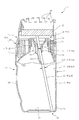
図1は、本実施の形態にかかる揮散装置1を示す図である。該揮散装置1は、液状薬剤を揮散する装置であり、液状薬剤としては、芳香剤や消臭剤や防虫剤等が挙げられる。 FIG. 1 is a diagram showing a volatilization apparatus 1 according to the present embodiment. The volatilization apparatus 1 is an apparatus that volatilizes a liquid chemical, and examples of the liquid chemical include a fragrance, a deodorant, and an insect repellent.
この揮散装置1は、無色透明の容器体11を備えており、該容器体11の上部には、蓋部12が外嵌した状態で固定されている。該蓋部12は、前記容器体11に下縁部が外嵌した下部構成部13と、該下部構成部13に支持された上部構成部14とによって構成されており、該上部構成部14は、前記下部構成部13に対して上下動可能に支持されている。
The volatilization apparatus 1 includes a colorless and
前記容器体11は、図2にも示すように、液状薬剤21を収容した容器本体22を備えており、該容器本体22は、図1及び図2に示したように、横長の略長方形状に形成された底面23と、該底面23の前縁より起立して前面を構成する正面24と、前記底面23の後縁より起立して後面と形成する背面25と、前記底面23の左縁より起立した左面26と、前記底面23の右縁より起立した右面27とによって容器状に形成さている。
As shown in FIG. 2, the
前記正面24は、中央部が前方に突出した湾曲面で構成されており、前記背面25は、中央部が後方に突出した湾曲面で構成されている。前記正面24の曲率は、前記背面25の曲率より大きく設定されており、前記正面24の突出量が大きくなるように形成されている。前記底面23の中央部には、上方へ向けて膨出形成された底面突出部31が形成されており、当該底面23は、前記底面突出部31と、該底面突出部31の外周部に設けられて平坦部32とによって構成されている。
The
前記容器本体22は、図2に示したように、上方へ向けて湾曲した容器天面41を備えており、該容器天面41には、当該容器本体22の内部と外部とを連通する円筒状の口部42が設けられている。該口部42には、中栓43が装着されており、該中栓43には、吸上芯44が挿通されている。
As shown in FIG. 2, the
該吸上芯44の上端部には、揮散体45が配設されており、該揮散体45は、前記蓋部12の前記下部構成部13に上下動可能に保持されている。この揮散体45は、前記吸上芯44に持ち上げられており、前記揮散体45は、その自重により前記吸上芯44の上端部と接触している。
A volatilizing
これにより、前記容器体11内の前記液状薬剤21を前記吸上芯44で前記揮散体45に吸い上げられるように構成されており、該揮散体45に吸い上げた前記液状薬剤21を前記蓋部12に設けられた揮散口46,・・・から揮散できるように構成されている(図1参照)。
Accordingly, the
前記中栓43は、図3及び図4にも示すように、中栓本体51からなり、該中栓本体51は、前記口部42に内嵌される円筒部52と、該円筒部52の上縁に設けられた円形リング状の天面53とを備えている。前記円筒部52の周面には、二本の突条54,54が円周方向に延設されており、当該中栓本体51を前記口部42に内嵌した状態で、前記突条54,54が前記口部42の内側面に密着するように構成されている。
As shown in FIGS. 3 and 4, the
前記天面53の周縁部は、前記円筒部52より外側に延出するように構成されており、当該中栓本体51には、鍔部61が一体形成されている。該鍔部61は、図3の(a)に示すように、対称箇所が直線状に切欠されており、左切欠部62と右切欠部63とが形成されている。
A peripheral portion of the
これにより、当該中栓本体51は、取付方向が定まるように構成されており、前記左切欠部62が左方に位置するとともに前記右切欠部63が右方に位置するように配置できるように構成されている。
As a result, the
前記天面53の内側には、図4に示したように、漏斗状の漏斗部71が一体形成されており、該漏斗部71は、前記天面53の内縁より下方へ向けて延出した大径円筒状の大径円筒部72と、該大径円筒部72の下縁より下方へ向かうに従って内側へ傾斜したテーパー状のテーパー部73と、該テーパー部73の下縁より下方へ向けて延出した小径円筒状の小径円筒部74とによって構成されている。
As shown in FIG. 4, a funnel-shaped
前記テーパー部73の中途部には、上下に貫通する貫通穴81が前方側に設けられており、該貫通穴81の下部には、当該貫通穴81に連通する円筒状の突出部82が形成されている。前記大径円筒部72の外周面には、上下方向に延在する補強リブ83が一体形成されており、該補強リブ83は、前方側に突出するように構成されている。
A through
これにより、当該中栓本体51を前記口部42に取り付けた際には、前記補強リブ83及び前記貫通穴81が前記容器本体22の前記正面24側に配置されるように構成されている(図2参照)。
Thus, when the inner plug
前記小径円筒部74は、上下方向に延在する直線状に形成されており、当該小径筒部74の内側には、前記吸上芯44を当該中栓本体51に挿通する際に当該吸上芯44を垂直方向に案内する挿通穴91が形成されている(図2参照)。
The small diameter
前記漏斗部71の下部には、横断面円弧状のガイド部101が一体形成されている。該ガイド部101は、前記小径円筒部74の前方側の下縁より下方へ向けて延出しており、当該ガイド部101の上部には前記補強リブ83の下部が一体形成され補強されている。このガイド部101は、下方へ向かうに従って前記背面25側へ向けて傾斜して延出するように設けられており(図2参照)、前記挿通穴91を挿通した前記吸上芯44を斜め方向に案内するように構成されている。
A
このとき、前記中栓43は、前記容器体11への取付方向が定められており、前記ガイド部101が下方へ向かうに従って前記背面25側へ傾斜するように設定されている。このため、このガイド部101で案内される前記吸上芯44を、前記容器体11の後方、すなわち前記背面25側へ向けて案内できるように構成されており、当該吸上芯44の下端部を前記底面23の前記平坦部32に配置できるように構成されている(図2参照)。
At this time, the mounting direction of the
このガイド部101の後方部分は、前記小径円筒部74に沿って垂直に切断されており、当該ガイド部101の後方部分の縁は、垂直に延在するように構成されている。これにより、当該中栓43を、上下方向に型開きされる金型によって形成できるように構成されている。
The rear portion of the
そして、図2に示したように、前記中栓43の前記小径円筒部74が形成する前記挿通穴91の内径寸法111は、該挿通穴91を挿通する前記吸上芯44の外形寸法112より大きく設定されており、前記吸上芯44が前記挿通穴91内で傾斜できるように構成されている。この傾斜状態において、前記吸上芯44の周面が前記小径円筒部74の前方側の上縁に当接するとともに当該小径円筒部74の後方側の下縁に当接した状態で、前記吸上芯44の下端が前記平坦部32内に配置されるように設計されている。
As shown in FIG. 2, the
以上の構成にかかる本実施において、容器体11の口部42に装着された中栓43には、吸上芯44を垂直方向に案内する挿通穴91が設けられている。このため、前記吸上芯44を前記中栓43に挿通する際には、前記吸上芯44を前記中栓43に対して垂直に移動するだけで、当該吸上芯44を前記挿通穴91に挿通することができる。
In this embodiment according to the above configuration, an
そして、この挿通穴91に挿入された前記吸上芯44は、前記中栓43に設けられたガイド部101によって斜め方向に案内することができる。このため、前記吸上芯44の下端部を、前記容器体11底面23の周縁部に配置することができる。
The
したがって、吸上芯を内嵌する円筒部が中栓の底部に斜めに設けられた構造上、前記吸上芯を前記円筒部の傾斜角に合わせて正確に挿入する必要があった従来と比較して、前記吸上芯44の挿通作業が容易となる。
Therefore, compared with the conventional case where the cylindrical portion into which the suction core is fitted is obliquely provided at the bottom of the inner plug, it is necessary to accurately insert the suction core according to the inclination angle of the cylindrical portion. Thus, the insertion work of the
また、前記吸上芯44を前記中栓43に対して垂直に移動するだけで、挿通作業が行えるので、前記中栓43の取付方向が多少ずれた場合であっても、また、吸上芯44の供給位置が多少ずれた場合であっても、前記吸上芯44を挿通することができる。このため、機械による挿通作業も可能となる。
Further, since the insertion work can be performed only by moving the
また、前記中栓43には、前記吸上芯44を前記挿通穴91に案内するテーパー状のテーパー部73が設けられている。このため、該テーパー部73上方の開口部分に前記吸上芯44を合わせて落とし込むだけで、当該吸上芯44を、前記挿通穴91に案内して挿入することができる。
The
これにより、前記吸上芯91の挿通作業がさらに容易となる。
Thereby, the insertion work of the said
さらに、前記中栓43には、前記ガイド部101が設けられており、該ガイド部101で案内される前記吸上芯44の下端部を、前記容器体11の背面25側に配置することができる。これにより、前記吸上芯44は、前記口部42に装着された前記中栓43より前記容器体11の前記背面25側へ向けて斜めに延在することとなる。
Further, the
このため、前記吸上芯44を前記容器体11正面24から見た際に、当該吸上芯44は、上方からまっすぐ下方へ延出するように見えるので、前記吸上芯44が前記中栓43より前記容器体11の側部へ向けて斜めに延在する場合と比較して、正面24からの見栄えが向上する。
For this reason, when the
これにより、外観品質を高めることができる。 Thereby, appearance quality can be improved.
加えて、前記挿通穴91の内径寸法111は前記吸上芯44の外径寸法112より大きく設定されており、該吸上芯44は、前記ガイド部101で斜め方向に案内された際に前記挿通穴91内で傾斜する。このため、該挿通穴91を挿通した前記吸上芯44が前記ガイド部101で斜め方向に案内される際に負荷がかからず、当該吸上芯44の挿通作業に力が不要となる。
In addition, an
これにより、前記吸上芯44の挿通作業がさらに容易となる。
Thereby, the insertion work of the said
また、前記ガイド部101で斜め方向にガイドされる際に、前記吸上芯44の折れ曲がりを防止することができる。このため、前記吸上芯101が硬い素材で形成された場合であっても、当該吸上芯44の不要な折曲を防止することができ、液状薬剤21の通水性を確保することができる。
Further, when the
(第二の実施の形態) (Second embodiment)
図5は、本発明の第二の実施の形態を示す図であり、第一の実施の形態と同一又は同等部分については、同符号を付して説明を割愛するとともに、異なる部分についてのみ説明する。 FIG. 5 is a diagram showing a second embodiment of the present invention, in which the same or equivalent parts as those in the first embodiment are denoted by the same reference numerals and description thereof is omitted, and only different parts are explained. To do.
すなわち、中栓43の小径円筒部74が形成する挿通穴91の内径寸法111は、該挿通穴91を挿通する可撓性の吸上芯44の外形寸法112と略同寸法に設定されている。これにより、前記小径円筒部74に挿入された前記可撓性の吸上芯44は、前記挿通穴91に沿って垂直に延在するとともに、前記ガイド部101によって撓んで斜めに曲げられており、当該吸上芯44の下端部を容器体11底面23の平坦部32に配置できるように構成されている。
That is, the
このような構成においては、前記吸上芯44の上部は、垂直に延在しているので、上端部の全面を揮散体45と接触させることができるので液状薬剤21の供給量を落とすことなく、しかも確実に前記吸上芯44を前記揮散体45に接触させることができる。
In such a configuration, since the upper portion of the
なお、前記両実施の形態では、前記吸上芯44の下端部は、前記容器体11の背面25側に配置される例について説明したが、これに限られず、たとえば前面24側に配置される場合であっても同様の効果を得ることができる。また、前記容器体11が不透明の場合には、前記吸上芯44の下端部が左右の側面26,27側に配置されても、また左右の斜め後ろ、斜め前に配置されても構わない。
In the above-described embodiments, the example in which the lower end portion of the
1 揮散装置
11 容器体
21 液状薬剤
25 背面
42 口部
43 中栓
51 中栓本体
73 テーパー部
91 挿通穴
101 ガイド
111 内径寸法
112 外形寸法
DESCRIPTION OF SYMBOLS 1
Claims (8)
前記吸上芯を挿通する際に該吸上芯を垂直方向に案内する挿通穴を前記中栓本体に設けるとともに、当該挿通穴を挿通した前記吸上芯を斜め方向に案内するガイド部を設けたことを特徴とする中栓。 In the inner plug in which the suction core is inserted into the inner plug body attached to the mouth of the container body containing the liquid medicine,
An insertion hole for guiding the suction core in the vertical direction when the suction core is inserted is provided in the inner plug body, and a guide portion for guiding the suction core inserted through the insertion hole in an oblique direction is provided. Inner plug characterized by that.
前記吸上芯を前記中栓に挿通する際に前記吸上芯を垂直方向に案内する挿通穴を前記中栓に設けるとともに、当該挿通穴を挿通した前記吸上芯を斜め方向に案内するガイド部を前記中栓に設けたことを特徴とする揮散装置。 A container body for storing a liquid medicine; an inner stopper attached to the mouth of the container body; and a suction core inserted through the inner stopper; and the liquid medicine in the container body is formed by the suction core. In the volatilization device that sucks up and volatilizes,
A guide hole is provided in the inner plug for guiding the suction core in a vertical direction when the suction core is inserted into the inner plug, and the guide is guided in an oblique direction through the insertion hole. A volatilization device characterized in that a portion is provided in the inner plug.
Priority Applications (4)
| Application Number | Priority Date | Filing Date | Title |
|---|---|---|---|
| JP2013245548A JP2015100649A (en) | 2013-11-28 | 2013-11-28 | Inside plug and vaporization device |
| KR1020167016800A KR20160091368A (en) | 2013-11-28 | 2014-11-21 | Inside plug and vaporization device |
| CN201480065369.9A CN105792857A (en) | 2013-11-28 | 2014-11-21 | Inside plug and vaporization device |
| PCT/JP2014/080872 WO2015080036A1 (en) | 2013-11-28 | 2014-11-21 | Inside plug and vaporization device |
Applications Claiming Priority (1)
| Application Number | Priority Date | Filing Date | Title |
|---|---|---|---|
| JP2013245548A JP2015100649A (en) | 2013-11-28 | 2013-11-28 | Inside plug and vaporization device |
Publications (1)
| Publication Number | Publication Date |
|---|---|
| JP2015100649A true JP2015100649A (en) | 2015-06-04 |
Family
ID=53198979
Family Applications (1)
| Application Number | Title | Priority Date | Filing Date |
|---|---|---|---|
| JP2013245548A Pending JP2015100649A (en) | 2013-11-28 | 2013-11-28 | Inside plug and vaporization device |
Country Status (4)
| Country | Link |
|---|---|
| JP (1) | JP2015100649A (en) |
| KR (1) | KR20160091368A (en) |
| CN (1) | CN105792857A (en) |
| WO (1) | WO2015080036A1 (en) |
Families Citing this family (5)
| Publication number | Priority date | Publication date | Assignee | Title |
|---|---|---|---|---|
| JP7359526B2 (en) * | 2016-12-28 | 2023-10-11 | 小林製薬株式会社 | Chemical liquid volatilizer |
| JP2020001743A (en) * | 2018-06-27 | 2020-01-09 | 小林製薬株式会社 | Medicine container and medicine volatilizer |
| JP2020116111A (en) * | 2019-01-23 | 2020-08-06 | 株式会社カーメイト | Inner plug for volatilizer and volatilizer |
| CN111605886A (en) * | 2020-05-21 | 2020-09-01 | 广东心之力科技发展有限公司 | Essential oil bottle with leak protection function |
| CN111591578A (en) * | 2020-06-02 | 2020-08-28 | 广东心之力科技发展有限公司 | Inner plug of aromatherapy glass bottle |
Citations (7)
| Publication number | Priority date | Publication date | Assignee | Title |
|---|---|---|---|---|
| JPH0957160A (en) * | 1995-08-18 | 1997-03-04 | U P C:Kk | Liquid jet device |
| JP2000350952A (en) * | 1995-08-18 | 2000-12-19 | U P C:Kk | Liquid spraying tool |
| JP2005034714A (en) * | 2003-07-17 | 2005-02-10 | Yoshino Kogyosho Co Ltd | Liquid jetting dispenser |
| JP2011011746A (en) * | 2009-06-30 | 2011-01-20 | Yoshino Kogyosho Co Ltd | Volatilization vessel of volatile liquid |
| WO2012026310A1 (en) * | 2010-08-27 | 2012-03-01 | エステー株式会社 | Volatilization device |
| WO2013005715A1 (en) * | 2011-07-01 | 2013-01-10 | 小林製薬株式会社 | Drug vaporizer |
| JP2013013482A (en) * | 2011-07-01 | 2013-01-24 | Kobayashi Pharmaceutical Co Ltd | Drug vaporizer |
Family Cites Families (3)
| Publication number | Priority date | Publication date | Assignee | Title |
|---|---|---|---|---|
| JPH0613730Y2 (en) | 1989-05-31 | 1994-04-13 | 小林製薬株式会社 | Suction mechanism for drug divergence container |
| CN2136610Y (en) * | 1992-10-10 | 1993-06-23 | 吴静秋 | Portable cover for water kettle |
| JP5319416B2 (en) * | 2009-06-24 | 2013-10-16 | エステー株式会社 | Volatilization equipment |
-
2013
- 2013-11-28 JP JP2013245548A patent/JP2015100649A/en active Pending
-
2014
- 2014-11-21 WO PCT/JP2014/080872 patent/WO2015080036A1/en active Application Filing
- 2014-11-21 KR KR1020167016800A patent/KR20160091368A/en not_active Application Discontinuation
- 2014-11-21 CN CN201480065369.9A patent/CN105792857A/en active Pending
Patent Citations (7)
| Publication number | Priority date | Publication date | Assignee | Title |
|---|---|---|---|---|
| JPH0957160A (en) * | 1995-08-18 | 1997-03-04 | U P C:Kk | Liquid jet device |
| JP2000350952A (en) * | 1995-08-18 | 2000-12-19 | U P C:Kk | Liquid spraying tool |
| JP2005034714A (en) * | 2003-07-17 | 2005-02-10 | Yoshino Kogyosho Co Ltd | Liquid jetting dispenser |
| JP2011011746A (en) * | 2009-06-30 | 2011-01-20 | Yoshino Kogyosho Co Ltd | Volatilization vessel of volatile liquid |
| WO2012026310A1 (en) * | 2010-08-27 | 2012-03-01 | エステー株式会社 | Volatilization device |
| WO2013005715A1 (en) * | 2011-07-01 | 2013-01-10 | 小林製薬株式会社 | Drug vaporizer |
| JP2013013482A (en) * | 2011-07-01 | 2013-01-24 | Kobayashi Pharmaceutical Co Ltd | Drug vaporizer |
Also Published As
| Publication number | Publication date |
|---|---|
| WO2015080036A1 (en) | 2015-06-04 |
| KR20160091368A (en) | 2016-08-02 |
| CN105792857A (en) | 2016-07-20 |
Similar Documents
| Publication | Publication Date | Title |
|---|---|---|
| WO2015080036A1 (en) | Inside plug and vaporization device | |
| JP5319416B2 (en) | Volatilization equipment | |
| JP5432090B2 (en) | Volatilization equipment | |
| US20190343261A1 (en) | Dropper-Type Cosmetics Container | |
| JP6861099B2 (en) | Volatilizer container and volatilizer | |
| KR20150091217A (en) | Sprayer | |
| JP2017072470A (en) | Capillary, sample collection tool, and sample collector | |
| JP6901369B2 (en) | Container with pump | |
| JP6090667B2 (en) | Inner plug with guide mechanism | |
| JPS622047Y2 (en) | ||
| JP6866035B2 (en) | Trigger type ejection container | |
| KR102097167B1 (en) | Needle assembly in using disposable syringe | |
| JP6716438B2 (en) | fountain pen | |
| JP2018090274A (en) | Volatilization device | |
| JP6138562B2 (en) | Liquid vaporizer | |
| JP6308392B2 (en) | Volatilization container | |
| JP2005178864A (en) | Vaporizer | |
| JP4171644B2 (en) | Chemical volatilization container | |
| JP2019099194A (en) | Volatilization body and volatilization device | |
| CN107414573A (en) | One kind can be manually rotated positioning tool | |
| JP3093418U (en) | Liquid air freshener container | |
| JP2013078533A (en) | Volatilizer | |
| JP2017080251A (en) | Volatile container | |
| JP5931706B2 (en) | Volatilizer container | |
| JP2007076144A (en) | Ink supplementing implement |
Legal Events
| Date | Code | Title | Description |
|---|---|---|---|
| A621 | Written request for application examination |
Free format text: JAPANESE INTERMEDIATE CODE: A621 Effective date: 20160901 |
|
| A131 | Notification of reasons for refusal |
Free format text: JAPANESE INTERMEDIATE CODE: A131 Effective date: 20170613 |
|
| A521 | Request for written amendment filed |
Free format text: JAPANESE INTERMEDIATE CODE: A523 Effective date: 20170710 |
|
| A131 | Notification of reasons for refusal |
Free format text: JAPANESE INTERMEDIATE CODE: A131 Effective date: 20170822 |
|
| A521 | Request for written amendment filed |
Free format text: JAPANESE INTERMEDIATE CODE: A523 Effective date: 20170922 |
|
| A02 | Decision of refusal |
Free format text: JAPANESE INTERMEDIATE CODE: A02 Effective date: 20171031 |