JP2013097894A - Battery wiring module - Google Patents
Battery wiring module Download PDFInfo
- Publication number
- JP2013097894A JP2013097894A JP2011237129A JP2011237129A JP2013097894A JP 2013097894 A JP2013097894 A JP 2013097894A JP 2011237129 A JP2011237129 A JP 2011237129A JP 2011237129 A JP2011237129 A JP 2011237129A JP 2013097894 A JP2013097894 A JP 2013097894A
- Authority
- JP
- Japan
- Prior art keywords
- fpc
- unit
- wiring module
- unit cell
- resin protector
- Prior art date
- Legal status (The legal status is an assumption and is not a legal conclusion. Google has not performed a legal analysis and makes no representation as to the accuracy of the status listed.)
- Pending
Links
- 230000001012 protector Effects 0.000 claims abstract description 63
- 229920005989 resin Polymers 0.000 claims abstract description 62
- 239000011347 resin Substances 0.000 claims abstract description 62
- 229920003002 synthetic resin Polymers 0.000 claims abstract description 6
- 239000000057 synthetic resin Substances 0.000 claims abstract description 6
- 238000001514 detection method Methods 0.000 claims description 36
- 230000003014 reinforcing effect Effects 0.000 description 24
- 238000000034 method Methods 0.000 description 8
- 238000005452 bending Methods 0.000 description 5
- 239000000853 adhesive Substances 0.000 description 4
- 230000001070 adhesive effect Effects 0.000 description 4
- 238000003780 insertion Methods 0.000 description 4
- 230000037431 insertion Effects 0.000 description 4
- RYGMFSIKBFXOCR-UHFFFAOYSA-N Copper Chemical compound [Cu] RYGMFSIKBFXOCR-UHFFFAOYSA-N 0.000 description 3
- 230000000694 effects Effects 0.000 description 3
- 239000002184 metal Substances 0.000 description 3
- 229910052751 metal Inorganic materials 0.000 description 3
- 230000002265 prevention Effects 0.000 description 3
- 210000000078 claw Anatomy 0.000 description 2
- 239000011889 copper foil Substances 0.000 description 2
- 239000011888 foil Substances 0.000 description 2
- 230000002093 peripheral effect Effects 0.000 description 2
- 238000005476 soldering Methods 0.000 description 2
- 229910000881 Cu alloy Inorganic materials 0.000 description 1
- 230000015572 biosynthetic process Effects 0.000 description 1
- 230000008602 contraction Effects 0.000 description 1
- 229910052802 copper Inorganic materials 0.000 description 1
- 239000010949 copper Substances 0.000 description 1
- 238000002955 isolation Methods 0.000 description 1
- 239000004973 liquid crystal related substance Substances 0.000 description 1
- 229920001721 polyimide Polymers 0.000 description 1
- 238000010248 power generation Methods 0.000 description 1
- 230000001681 protective effect Effects 0.000 description 1
- 239000004065 semiconductor Substances 0.000 description 1
- 239000010935 stainless steel Substances 0.000 description 1
- 229910001220 stainless steel Inorganic materials 0.000 description 1
Images


Classifications
-
- Y—GENERAL TAGGING OF NEW TECHNOLOGICAL DEVELOPMENTS; GENERAL TAGGING OF CROSS-SECTIONAL TECHNOLOGIES SPANNING OVER SEVERAL SECTIONS OF THE IPC; TECHNICAL SUBJECTS COVERED BY FORMER USPC CROSS-REFERENCE ART COLLECTIONS [XRACs] AND DIGESTS
- Y02—TECHNOLOGIES OR APPLICATIONS FOR MITIGATION OR ADAPTATION AGAINST CLIMATE CHANGE
- Y02E—REDUCTION OF GREENHOUSE GAS [GHG] EMISSIONS, RELATED TO ENERGY GENERATION, TRANSMISSION OR DISTRIBUTION
- Y02E60/00—Enabling technologies; Technologies with a potential or indirect contribution to GHG emissions mitigation
- Y02E60/10—Energy storage using batteries
Landscapes
- Secondary Cells (AREA)
- Connection Of Batteries Or Terminals (AREA)
Abstract
Description
本発明は、電池用配線モジュールに関する。 The present invention relates to a battery wiring module.
従来、正極及び負極を有する複数の単電池を備えた単電池群に取り付けられる電池用配線モジュールとして、特許文献1に記載のものが知られている。この電池用配線モジュールは、合成樹脂製の樹脂プロテクタと、樹脂プロテクタに配設されるフレキシブルプリント基板(以下、FPCと記載することがある)と、FPCに実装されたサーミスタと、を備える。
Conventionally, the thing of
樹脂プロテクタは、サーミスタ及びFPCを単電池に向かって弾性的に付勢する付勢部材を備えている。付勢部材はサーミスタと直接に接触するようになっている。付勢部材によってサーミスタが単電池に向かって付勢されることにより、単電池の温度がサーミスタによって検知されるようになっている。 The resin protector includes a biasing member that elastically biases the thermistor and the FPC toward the single cell. The biasing member is in direct contact with the thermistor. When the thermistor is urged toward the unit cell by the urging member, the temperature of the unit cell is detected by the thermistor.
しかしながら上記の構成によると、付勢部材はFPCを押圧するようになっている。すると、FPCに過度に力が加えられることが懸念される。FPCは、絶縁性の合成樹脂からなるフィルムと、このフィルムに形成された金属箔からなる導電路と、を備える。FPCに過度の力が加えられると、フィルムが変形したり、導電路が破断する等の不具合が生じることが懸念される。 However, according to the above configuration, the urging member presses the FPC. Then, there is a concern that an excessive force is applied to the FPC. The FPC includes a film made of an insulating synthetic resin and a conductive path made of a metal foil formed on the film. When an excessive force is applied to the FPC, there is a concern that the film may be deformed or a problem such as breakage of the conductive path may occur.
また、従来技術においては、サーミスタが直接に接触しているのは付勢部材であり、サーミスタと単電池との間には、FPCが介在している。このため、サーミスタが直接に検知するのは付勢部材の温度であり、単電池の温度は、合成樹脂からなるフィルム、及び金属箔からなる導電路を介して間接的にしか検知することができない。このため、従来技術によっては、単電池の温度を確実に検知することができないという問題があった。 In the prior art, the thermistor is in direct contact with the urging member, and the FPC is interposed between the thermistor and the single cell. For this reason, it is the temperature of the urging member that the thermistor directly detects, and the temperature of the unit cell can only be indirectly detected through a film made of synthetic resin and a conductive path made of metal foil. . For this reason, there existed a problem that the temperature of a cell could not be detected reliably depending on the prior art.
本発明は上記のような事情に基づいて完成されたものであって、フレキシブルプリント基板を保護すると共に、単電池の温度を確実に検知する電池用配線モジュールを提供することを目的とする。 This invention is completed based on the above situations, Comprising: It aims at providing the wiring module for batteries which protects a flexible printed circuit board and detects the temperature of a single cell reliably.
本発明は、正極及び負極の電極端子を備えた複数の単電池を備えた単電池群に取り付けられる電池用配線モジュールであって、合成樹脂製の樹脂プロテクタと、前記樹脂プロテクタに配設されるフレキシブルプリント基板と、前記フレキシブルプリント基板の側縁から延出されて前記単電池に向かって配索される延出片と、前記延出片に取り付けられると共に前記単電池と接触して前記単電池の温度を検知する温度検知部と、を備え、前記樹脂プロテクタは前記延出片及び前記温度検知部を前記単電池に押圧して、前記温度検知部を前記単電池と接触させる押圧部を備える。 The present invention is a battery wiring module that is attached to a unit cell group including a plurality of unit cells each having a positive electrode electrode and a negative electrode terminal. The resin protector is made of a synthetic resin, and is disposed in the resin protector. A flexible printed circuit board; an extended piece extending from a side edge of the flexible printed circuit board and routed toward the single battery; and the single battery attached to the extended piece and in contact with the single battery. A temperature detection unit that detects the temperature of the battery, and the resin protector includes a pressing unit that presses the extension piece and the temperature detection unit against the unit cell to bring the temperature detection unit into contact with the unit cell. .
本発明によれば、押圧部によって押圧されるのは延出片と温度検知部なので、フレキシブルプリント基板は押圧部からの力を受けないようになっている。これにより、フレキシブルプリント基板を保護することができる。 According to the present invention, since it is the extension piece and the temperature detection part that are pressed by the pressing part, the flexible printed circuit board does not receive the force from the pressing part. Thereby, a flexible printed circuit board can be protected.
また、本発明によれば、温度検知部は押圧部に向かって押圧される。これにより、単電池の温度を確実に検知することができる。 Moreover, according to this invention, a temperature detection part is pressed toward a press part. Thereby, the temperature of a cell can be detected reliably.
本発明の実施態様としては以下の態様が好ましい。
前記押圧部は、前記樹脂プロテクタから前記単電池側に向かって僅かに突出して形成されており、前記温度検知部は前記押圧部と前記単電池との間に配されていることが好ましい。
As embodiments of the present invention, the following embodiments are preferable.
The pressing portion is preferably formed to protrude slightly from the resin protector toward the unit cell, and the temperature detection unit is preferably disposed between the pressing unit and the unit cell.
上記の態様によれば、樹脂プロテクタが単電池群に取り付けられた状態において、温度検知部は、単電池と押圧部との間に挟まれることにより、単電池と確実に接触する。これにより単電池の温度を確実に検知することができる。 According to said aspect, in the state in which the resin protector was attached to the cell group, the temperature detection part is reliably contacted with a cell by being pinched | interposed between a cell and a press part. Thereby, the temperature of a cell can be detected reliably.
前記延出片は、前記フレキシブルプリント基板の側縁に沿って細長い帯状に形成された後、直角に折り曲げられてなることが好ましい。 The extension piece is preferably formed in a strip shape along a side edge of the flexible printed circuit board and then bent at a right angle.
上記の態様によれば、フレキシブルプリント基板の側縁に沿って細長い帯状に形成された延出片を直角に折り曲げるという簡易な手法により、延出片を形成できる。また、フレキシブルプリント基板の側縁から直角に延出片を延設する場合に比べて、1つのフレキシブルプリント基板を作成するために必要とされる面積を小さくすることができるので、歩留まりを向上させることができる。 According to the above aspect, the extension piece can be formed by a simple method of bending the extension piece formed in an elongated strip shape along the side edge of the flexible printed board at a right angle. Moreover, since the area required for producing one flexible printed circuit board can be made small compared with the case where the extending piece is extended at right angles from the side edge of the flexible printed circuit board, the yield is improved. be able to.
前記樹脂プロテクタには前記フレキシブルプリント基板を収容する収容部が形成されており、前記樹脂プロテクタには、前記収容部から導出された前記延出片を前記押圧部に案内する案内部が形成されていることが好ましい。 The resin protector is formed with a housing portion for housing the flexible printed circuit board, and the resin protector is formed with a guide portion for guiding the extended piece led out from the housing portion to the pressing portion. Preferably it is.
上記の態様によれば、延出片は、収容部から導出され、案内部によって押圧部へと案内される。これにより、温度検知手段が押圧部によって確実に単電池に押圧されるので、単電池の温度を確実に検知することができる。 According to the above aspect, the extension piece is led out from the housing portion and guided to the pressing portion by the guide portion. Thereby, since the temperature detection means is reliably pressed by the unit cell by the pressing part, the temperature of the unit cell can be detected reliably.
前記フレキシブルプリント基板は電子部品及び前記温度検知部が実装された実装面を有し、前記樹脂プロテクタが前記単電池群に取り付けられた状態において、前記電子部品は前記フレキシブルプリント基板に対して前記単電池と反対側に位置して配されており、前記温度検知部は前記延出片が折り曲げられることにより前記延出片に対して前記単電池側に位置して配されていることが好ましい。 The flexible printed circuit board has a mounting surface on which an electronic component and the temperature detection unit are mounted. In a state where the resin protector is attached to the single battery group, the electronic component is connected to the flexible printed circuit board. It is preferable that the temperature detection unit is disposed on the side opposite to the battery, and the temperature detection unit is disposed on the unit cell side with respect to the extension piece by bending the extension piece.
上記の態様によれば、電子部品と温度検知部とをフレキシブルプリント基板の実装面に対して同一工程で実装することができる。更に、温度検知部と単電池とを直接に接触させることができるので、単電池の温度を更に確実に検知することができる。 According to said aspect, an electronic component and a temperature detection part can be mounted in the same process with respect to the mounting surface of a flexible printed circuit board. Furthermore, since the temperature detection unit and the single cell can be brought into direct contact with each other, the temperature of the single cell can be detected more reliably.
前記フレキシブルプリント基板には、前記電極端子と電気的に接続されて前記単電池の電圧を検知するランドが形成されていることが好ましい。 The flexible printed circuit board is preferably formed with lands that are electrically connected to the electrode terminals and detect the voltage of the unit cells.
上記の態様によれば、フレキシブルプリント基板に形成されたランドによって、単電池の電圧を検知することができるので、電圧検知用の電線を、別途、配索する必要がない。これにより、電池用配線モジュールを小型化できる。 According to said aspect, since the voltage of a cell can be detected with the land formed in the flexible printed circuit board, it is not necessary to wire the electric wire for voltage detection separately. Thereby, the wiring module for batteries can be reduced in size.
前記樹脂プロテクタには、異なる前記単電池の前記電極端子同士を接続する接続部材が収容されていることが好ましい。 The resin protector preferably contains a connection member that connects the electrode terminals of the different cells.
上記の態様によれば、樹脂プロテクタを単電池群に取り付けることにより、異なる単電池の電極端子同士を電気的に接続することができる。 According to said aspect, the electrode terminal of a different cell can be electrically connected by attaching a resin protector to a cell group.
本発明によれば、フレキシブルプリント基板を保護することが可能であると共に、単電池の温度を確実に検知することができる。 ADVANTAGE OF THE INVENTION According to this invention, while being able to protect a flexible printed circuit board, the temperature of a cell can be detected reliably.
<実施形態>
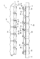
本発明の一実施形態を図1ないし図25に基づいて説明する。本実施形態に係る電池モジュール10は、例えば、電気自動車またはハイブリッド自動車等の車両(図示せず)の駆動源として使用される。電池モジュール10は、図1に示すように、複数(本実施形態では14個)の単電池11が横並びに配置された単電池群12と、単電池群12に取り付けられて複数の単電池11を接続する電池用配線モジュール13とを備える。以下の説明においては、図1の上方を上方とし、下方を下方とする。
<Embodiment>
An embodiment of the present invention will be described with reference to FIGS. The
(単電池群12)
図1に示すように、単電池11は、扁平な略直方体形状をなしており、その内部には図示しない発電要素が収容されている。単電池11の上面には、両端部寄りの位置に、一対の電極端子14,14が上方に突出して形成されている。一対の電極端子14,14の一方は正極であり、他方は負極である。電極端子14の外周面にはねじ山が形成されている。各単電池11の正負の向きは、互いに隣り合う単電池11において逆向きになっており、これにより互いに異極の電極端子14が隣り合うように構成されている。電極端子14は電池用配線モジュール13に収容されたバスバー15(接続部材の一例)を挟んでナット(図示せず)で締め付けられる。複数の単電池11は、詳しくは図示しないが、保持板等の公知の固定手段により固定されている。
(Single cell group 12)
As shown in FIG. 1, the
(電池用配線モジュール13)
図2に示すように、単電池群12の上面には、単電池11の並び方向に沿って細長い電池用配線モジュール13が配置されている。
(Battery wiring module 13)
As shown in FIG. 2, elongated
電池用配線モジュール13は大まかには、電極端子14間を接続する複数のバスバー15が保持された樹脂プロテクタ16と、樹脂プロテクタ16に保持されたフレキシブルプリント基板17(以下、単にFPC17という。)とを備えている。後記するように、樹脂プロテクタ16は2本が互いに平行に配される一方、FPC17はU字形をなして形成されている。
The
(FPC17)
先にFPC17を説明する。FPC17は、図3及び図4に示すように、ポリイミドフィルムや液晶状フィルム等からなる絶縁性のベースフィルムの一面、または両面にプリント配線技術により導電路18(図5参照)が形成された構造である。
(FPC17)
First, the
FPC17は全体としては、2列に並ぶ第1FPC帯19と第2FPC帯20の一端部同士を連結部56で連結してなるU字形に形成されている。
As a whole, the
第1FPC帯19(図4の上側)は、裏面のみに導電路18が形成されている。一方、第2FPC帯20(図4の下側)は裏面と表面との両面に導電路18が形成されている。したがって、第2FPC帯20の表面が、電子部品23等が実装される実装面21となっている。また、第1FPC帯19、及び第2FPC帯20の裏面に形成された導電路18は、後述するバスバー15と電気的に接続されて、電極端子14における単電池11の電圧を検知する電圧検知導電路22とされる。
In the first FPC band 19 (upper side in FIG. 4), the
第1FPC帯19は、長さ方向に沿って7つの単位領域24Aに等分されている。各単位領域24Aの長さは、隣り合う単電池11を2個を合わせた厚さにほぼ匹敵する。隣り合う各単位領域24Aの間には、余長吸収機能を果たす余長吸収部25が、下向きに膨出されている。
The
第2FPC帯20は、長さ方向に沿って6つの単位領域に分割されており、ここで中央部の4つの単位領域24Bは、第1FPC帯19の単位領域24Aと同じく単電池11の2個分の厚さに相当する長さを有するのに対して、両端の2個の単位領域24Cは、単電池11の3個分の厚さに相当する長さを有している。隣り合う各単位領域24B,24Cの間には、同じく余長吸収機能を果たす余長吸収部25が、下向きに膨出されている。
The
第1FPC帯19と第2FPC帯20とでは、それぞれの単位領域24Aと、24B,24Cとが、単電池11の1個分だけピッチがずれて配されている。
In the
以下の説明において、単位領域24A,24B,及び24Cについて共通の説明を行う場合は、単位領域24として説明する場合がある。
In the following description, when the
第1FPC帯19と第2FPC帯20の裏面には、詳しくは後記するように、バスバー15に一体形成された補強板26が、各単位領域24ごとに固定されるようになっている。バスバー15は単電池11の電圧に関する情報を取り込む検知端子として併せて機能するようになっている。第1FPC帯19と第2FPC帯20の裏面には、図5に概略的に示すように、各単位領域24ごとにランド27と、同ランド27から導出された電圧検知導電路22が形成されており、バスバー15の補強板26はランド27と電気的に接続されるようになっている。
On the back surfaces of the
なお、各単位領域24には、同図に示すように、ランド27及び同ランド27と接続された電圧検知導電路22と異なる複数本の銅箔28が、上記のランド27及び電圧検知導電路22とは、電気的に絶縁された形態で形成されている。また、余長吸収部25にも、電圧検知導電路22と異なる銅箔28が形成されている。
In each
第2FPC帯20の表面には、図10に参照して示すように、例えば各単位領域24B、24Cごとに、電子部品23がリフロー半田付け等の公知の手法により導電路18に対して接続されている。電子部品23は、CPU23Aを含む。ランド27と接続された電圧検知導電路22にはCPU23Aが接続されている。このCPU23Aは、バスバー15を介して取得した単電池11の電圧に関する情報から単電池11の電圧を検知するようになっている。
As shown in FIG. 10, the
バスバー15とCPU23Aとは電圧検知導電路22で接続されている。CPU23Aは、バスバー15から単電池11の電圧値を取得し、単電池11の電圧が所定の正常値内であるか否かを監視するようになっている。
The
第2FPC帯20における中央部の1個の単位領域24Bと、両端の2個の単位領域24Cとには、その内側縁から延出された延出片30が形成されている。延出片30は、単位領域24の内側縁に沿うと共に細長い帯状に切り出された細片が、FPC17の延びる方向に対して直角に曲げ形成されたのち、その先端部がU字形に曲げられた形状をなしている。延出片30の先端部の下面(単電池11側の面)にはサーミスタ29(温度検知部の一例)が装着されるようになっている(図12参照)。このサーミスタ29は対応する単電池11と直接に接触して、この単電池11の温度を検出し、その温度検知信号を、導電路18を介してCPU23Aに送信するように機能する。CPU23Aは、サーミスタ29から取得した単電池11の温度が所定の正常値内であるか否かを監視するようになっている。
An
第2FPC帯20の自由端には、外部ECU(図示せず)と接続されるコネクタ部32が取り付けられるようになっている。コネクタ部32は、導電路18を介してCPU23Aと接続されている。CPU23Aは、外部ECUから情報を取得すると共に、外部ECUに対して、単電池11の電圧、及び単電池11の温度等の、単電池11に関する情報を送信するようになっている。
A
(バスバー15)
次に、隣り合う単電池11の電極端子14間を接続するバスバー15について説明する。バスバー15は、一部既述したように、単電池群12側の電圧を検知する検知端子として併せて機能する。バスバー15は、銅、銅合金、ステンレス鋼(SUS)等の金属板をプレス加工して形成される。バスバー15は、13個の2穴バスバー15Aと、2個の1穴バスバー15Bとの、2種類のバスバー15からなる。
(Bus bar 15)
Next, the
2穴バスバー15Aは、図6及び図7に示すように、単電池11の電極端子14が挿通される2個の端子挿通孔33が所定間隔を開けて開口された長寸の平面長方形をなす本体部34Aを備えている。一方、1穴バスバー15Bは、図8及び図9に示すように、単電池11の電極端子14が挿通される単一の端子挿通孔33を開口した長寸の平面長方形をなす本体部34Bを備えている。
As shown in FIGS. 6 and 7, the two-
各バスバー15A,15Bには、補強板26A,26Bが一体形成されている。2穴バスバー15Aを例に採ると、本体部34Aの一側縁側に垂直部35Aを介して補強板26Aが一段上がった段差状に形成されている。補強板26Aは、第1FPC帯19の単位領域24Aと第2FPC帯20の単位領域24Bにおける裏面のほぼ全面に当たる平面長方形に形成されている。なお、第2FPC帯20の両端の単位領域24Cでは、2/3の領域に当たるようになっている。
Reinforcing
1穴バスバー15Bでは、補強板26Bは同じく本体部34Bの一側縁側に垂直部35Bを介して一段上がった段差状に形成されている。1穴バスバー15Bの補強板26Bは、本体部34Bと同様に短寸に形成され、第2FPC帯20の両端の単位領域24Cにおける残りの1/3の領域に当たるようになっている。
In the 1-
両バスバー15A,15Bの補強板26A,26Bにおけるほぼ四隅に対応する位置には、位置決め用の貫通孔36が形成されている。なお、FPC17の各単位領域24にも、上記した補強板26A,26Bの貫通孔36と整合した貫通孔37が形成されている。
Positioning through
両バスバー15A,15Bの補強板26A,26Bにおける周縁部には、後記する接着剤の進入を許容する進入孔38が適宜に開口されている。
In the peripheral portions of the reinforcing
(樹脂プロテクタ16)
樹脂プロテクタ16は、一部既述したように、FPC17の2辺を構成する第1FPC帯19と第2FPC帯20とに対応して、2本が互いに平行に配されている。
(Resin protector 16)
As described above, the
樹脂プロテクタ16のうち、図2の上側に位置する第1樹脂プロテクタ16Aは、第1FPC帯19の単位領域24Aと対応するようにして、7個の連結ユニット39Aから構成されている。
Among the
また、樹脂プロテクタ16のうち図2の下側に位置する第2樹脂プロテクタ16Bは、第2FPC帯20の単位領域24B,24Cと対応するようにして、6個の連結ユニット39Bから構成されており、ここで中央部の4個の連結ユニット39Bは、上記した第1樹脂プロテクタ16Aを構成する連結ユニット39Aと長さが同じであるのに対して、両端の2個の連結ユニット39Cは、単位領域24Cに対応して全体として長いものに形成されている。
Further, the
連結ユニットの基本的な構造を、第2樹脂プロテクタ16Bの中央部に配される連結ユニット39Bを例にして説明する。
The basic structure of the connecting unit will be described by taking the connecting
連結ユニット39Bは、図13ないし図15に示すように、2穴バスバー15Aにおける本体部34Aが収容される本体部収容部40Bと、FPC17が収容されるFPC収容部41B(収容部の一例)とが並んで形成されているとともに、FPC収容部41Bの側縁には、FPC収容部41Bの上面を覆うカバー42Bがヒンジ43を介して揺動開閉可能に形成されている。
As shown in FIGS. 13 to 15, the connecting unit 39 </ b> B includes a main
本体部収容部40Bは、2穴バスバー15Aの本体部34Aを上方から緊密に挿入可能な箱形に形成されており、同本体部収容部40Bの底面には、本体部34Aにおける2個の端子挿通孔33の形成位置を外部に開口するべく2個の窓孔44が形成されている。本体部収容部40BにおけるFPC収容部41Bと反対側の側壁には、本体部34Aの一側縁における長さ方向の中央部に係止して抜け止めする係止爪45が形成されている。
The main
FPC収容部41Bは、上記した本体部収容部40Bにおける側壁の略中央高さ位置から側方に張り出すようにして形成されている。したがって当該側壁の上部側は切除されている。FPC収容部41Bには、FPC17の下側に、バスバー15の補強板26が載置されるようになっている。FPC収容部41Bの四隅にはピン46が立てられており、このピン46が、互いに整合する、補強板26A,26BとFPC17とに整合して開口された貫通孔36,37に貫通可能となっている。
The
FPC収容部41Bの前後の端縁のうち前縁(図14の左側)には、一対の連結片47が突出形成されているとともに、後縁(図14の右側)には、同連結片47を摺動可能に受け入れる受け部48が形成されている。
A pair of connecting
カバー42Bは、FPC収容部41Bの上面の全面を覆うことが可能な大きさに形成されている。カバー42Bの裏面には、その中央部に、FPC17の表面に実装された電子部品23を嵌めて逃がす浅い逃がし凹部49が形成されており、その回りに押さえリブ50が形成されている。
The
カバー42Bの揺動端側の端縁における両端には、一対のロック片51が裏側に突出して形成されている一方、上記した本体部収容部40Bの側壁における両端部には、ロック片51が弾性的に係止するロック部52が設けられている。また、カバー42Bの裏面の四隅には、FPC収容部41Bの四隅に立てられたピン46の先端が嵌る嵌合孔53が形成されている。
A pair of
図18に示すように、第2樹脂プロテクタ16Bの自由端側に配される連結ユニット39Cは、本体部収容部40Cが、2穴バスバー15Aにおける本体部34Aと、1穴バスバー15Bの本体部34Bとを隔絶して収容可能な形状となっている。FPC収容部41Cは、第2FPC帯20における自由端側の単位領域24Cに裏張りされた2穴バスバー15Aの補強板26Aと1穴バスバー15Bの補強板26Bが載置可能な形状に形成され、さらにコネクタ部32が設けられた第2FPC帯20の自由端が載置可能なコネクタ部載置部54が延出形成されている。
As shown in FIG. 18, the connecting
カバー42Cは、FPC収容部41Cの上面の全面を覆うことが可能な大きさに形成されているとともに、上記のコネクタ部32を覆う保護カバー55が一体形成されている。
The
第2樹脂プロテクタ16Bの連結端側に配される連結ユニット39Dは、本体部収容部40Dが、2穴バスバー15Aにおける本体部34Aと、1穴バスバー15Bの本体部34Bとを隔絶して収容可能な形状となっている一方、FPC収容部41Dは、第2FPC帯20における連結端側の単位領域24Cに裏張りされた2穴バスバー15Aの補強板26Aと1穴バスバー15Bの補強板26Bが載置可能な形状であって、かつ第1FPC帯19と第2FPC帯20との連結部56の端部が載置される連結部載置部57が延出形成されている。カバー42Dは、FPC収容部41Dから連結部載置部57に亘る上面の全面を覆うことが可能な大きさに形成されている。
In the
両連結ユニット39C,39Dともに、その他の形状については、上記した連結ユニット39Bと同様である。
Both the connecting
第1樹脂プロテクタ16Aを構成する7個の連結ユニット39Aは、本体部収容部40A、FPC収容部41A及びカバー42Aを備える等の基本的な構造について、上記した第2樹脂プロテクタ16Bの中央部の連結ユニット39Bと同様である。なお、第1樹脂プロテクタ16Aを構成する連結ユニット39Aには、カバー42Aの裏面において、逃がし凹部49が形成されておらず、裏面のほぼ全面にわたって押さえリブ50が形成されている。この構成において、第1樹脂プロテクタ16Aを構成する連結ユニット39Aは、第2樹脂プロテクタ16Bの中央部の連結ユニット39Bと異なっている。
The seven connecting
さて、図22及び図23に示すように、各連結ユニット39A〜39Dにおける本体部収容部40A〜40Dの外面には、FPC収容部41A〜41Dから延出された延出片30を保持する溝状をなす保持部58が形成されている。この保持部58内に、延出片30の先端を挟み込むことにより、延出片30は保持部58によって所定の位置に保持される。
Now, as shown in FIG.22 and FIG.23, the groove | channel which hold | maintains the
また、図23及び図24に示すように、各連結ユニット39A〜39Dにおける本体部収容部40A〜40Dの外面には、延出片30に実装されたサーミスタ29を単電池11に向かって押圧する押圧部59が形成されている。押圧部59は、本体部収容部40A〜40Dの外面から突出するリブ状に形成されており、側方から見て略U字状をなしている。押圧部59の下面は、連結ユニット39A〜39Dの下面よりも下方(単電池11側)に僅かに突出して形成されている。押圧部59の下面には、下方に突出して、サーミスタ29が押圧部59から外れることを防止する外れ止め突起60が形成されている。外れ止め突起60の、押圧部59の下面からの突出高さ寸法は、サーミスタ29の高さ寸法よりも小さく設定されている。押圧部59は、上下方向に弾性変形可能に形成されている。
Further, as shown in FIGS. 23 and 24, the
本体部収容部39A〜39Dの外面には、FPC収容部41A〜41Dから導出された延出片30を押圧部59へと案内する溝状をなす案内部61が形成されている。案内部61は本体部収容部39A〜39Dの外面に沿う溝状に形成されている。この案内部61の内部に延出片30を挟み込むことにより、延出片30は押圧部59へと案内されるようになっている。案内部61の内壁には、延出片30が案内溝から上方へ外れることを抑制する外れ止め部62が内方に突出して形成されている。
On the outer surface of the main
図25に示すように、サーミスタ29は、押圧部59に延出片30が保持された状態で、延出片30に対して単電池11側(下側)に配されるようになっている。これにより、電池用配線モジュール13が単電池群12に取り付けられた状態で、サーミスタ29は単電池11の上面と直接に接触するようになっている。図25には、電池用配線モジュール13が単電池群12に取り付けられる前の状態における押圧部59の状態が記載されている。なお、図25には、単電池群12に電池用配線モジュール13が取り付けられた状態における単電池11の上面の位置が、想像線(二点鎖線)で示されている。
As shown in FIG. 25, the
電池用配線モジュール13が単電池群12に取り付けられた状態においては、単電池11の上面は、サーミスタ29と下方から当接し、サーミスタ29を上方に押圧する。これにより、押圧部59は、サーミスタ29及び延出片30を介して上方に押圧されて、上方に弾性撓み変形する。この結果、押圧部59においては、下向きの弾発力が発生し、この弾発力により、サーミスタ29は単電池11の上面に密着するようになっている。
In a state where the
(組立手順)
本実施形態に係る電池モジュール10の組立手順の一例を説明する。図1に示すように、図示14個の単電池11を、隣り合う単電池11において正負が逆向きとなった形態で重ねて並べることにより、単電池群12が形成される。
(Assembly procedure)
An example of the assembly procedure of the
一方、図3に示すように、第1FPC帯19と第2FPC帯20とを連結部56で連結したU字形をなすFPC17が形成され、図10に示すように、第2FPC帯20の表面に対し、CPU23A及びサーミスタ29を含む電子部品23を、同一の工程において、リフロー半田付けにより実装する。併せてコネクタ部32も装着する。その後、第2FPC帯20から切り出された後に曲げ形成されて、所定形状の延出片30が形成される。
On the other hand, as shown in FIG. 3, a
上記のように電子部品23等が実装されたFPC17に対して、補強板26A,26Bが貼着される。第1FPC帯19では、7つの単位領域24Aの裏面に対して、それぞれ2穴バスバー15Aの補強板26Aが貼着される。より詳細には、単位領域24Aの裏面全面に導電性接着剤が塗布されたのち、2穴バスバー15Aの本体部34Aが内側(第2FPC帯20側)を向いた姿勢で、補強板26Aが、貫通孔36,37を整合させつつ対応する単位領域24Aの裏面に押し付けられることで貼り付けられる。
Reinforcing
第2FPC帯20では、その中央の4つの単位領域24Bの裏面については、2穴バスバー15Aの補強板26Aが、上記と同じ要領により導電性接着剤を介して全面に貼り付けられる。両端の単位領域24Cの裏面には、2穴バスバー15Aの補強板26Aと1穴バスバー15Bの補強板26Bとが、間隔を開けて内外に並んだ形態で、同じく導電性接着剤を介して全面に貼り付けられる。以上により、バスバー15を一体的に取り付けたFPC17が形成される。
In the
一方、7個の連結ユニット39Aが、連結片47を受け部48に挿通しつつ繋がれることで第1樹脂プロテクタ16Aが形成され、また、連結ユニット39C,39Dの間に4個の連結ユニット39Bを配して、同様に連結片47を受け部48に挿通しつつ繋ぐことによって第2樹脂プロテクタ16Bが形成される。この第1樹脂プロテクタ16Aと第2樹脂プロテクタ16Bとが、所定間隔を開けて互いに平行に配される。
On the other hand, the seven connecting
この状態から、FPC17が樹脂プロテクタ16A,16Bに対して収容される。詳細には、FPC17に装着されたバスバー15A,15Bの本体部34A,34Bが対応する連結ユニット39A〜39Dの本体部収容部40A〜40Dの底部まで押し込まれ、係止爪45により抜け止めされる。それに併せて、同バスバー15A,15Bの補強板26A,26B並びにその補強板26A,26Bが貼着されたFPC17が、FPC収容部41に立てられたピン46を貫通孔36,37に貫通させつつFPC収容部41A〜41D上に載置される。
From this state, the
続いて、FPC17の側縁に形成された延出片30を、FPC収容部41から導出し、案内部61の内部に挟みこむ。次に、押圧部59の下面に、サーミスタ29が延出片30に対して押圧部59と反対側に位置する姿勢で、延出片30及びサーミスタ29を配する。更に、延出片30の端部を保持部58の内部に挟みこむことにより、延出片30を保持する。
Subsequently, the extending
カバー42A〜42Dは、裏面の嵌合孔53にピン46の先端を嵌めて位置合わせされつつ閉じられ、正規に閉じられたところで、ロック片51が相手のロック部52に係止して閉鎖状態にロックされる。
The
これにより、第1FPC帯19と第2FPC帯20の表面、並びにコネクタ部32の上面が覆われた形態の完成品としての電池用配線モジュール13が形成される。
As a result, the
以上のように形成された電池用配線モジュール13が、図1に示すように、単電池群12の上面の所定位置に被せられ、2穴バスバー15A及び1穴バスバー15Bの端子挿通孔33に、単電池11の対応する電極端子14をそれぞれ挿通し、各電極端子14にナットを螺合させて締め付けることにより、電極端子14とバスバー15とが接続される。
As shown in FIG. 1, the
各電極端子14にナットを締め付けることにより、電池用配線モジュール13は単電池11に接近する方向の力を受ける。すると、図25に示すように、押圧部59は、延出片30及びサーミスタ29を介して、単電池11の上面から上方に押圧される。すると、押圧部59は上方に弾性変形し、その反作用として、下方に弾発力を及ぼす。これにより、押圧部59は、延出片30及びサーミスタ29を下方に(単電池11に向かう方向)に押圧する。
By tightening a nut on each
以上により、電池モジュール10が形成されることになる。なお、このときFPC17に形成されたヒンジ43部が伸縮して隣り合う連結ユニット39A〜39Dの間隔が変化しつつ樹脂プロテクタ16A,16Bの長さが調整され、単電池群12との取り付け誤差が吸収される。
Thus, the
(本実施形態の作用及び効果)
続いて、本実施形態の作用及び効果について説明する。本実施形態によれば、押圧部59によって単電池11に押圧されるのは延出片30とサーミスタ29なので、FPC17の本体部分は押圧部59からの力を受けないようになっている。これにより、FPC17を保護することができる。
(Operation and effect of this embodiment)
Then, the effect | action and effect of this embodiment are demonstrated. According to the present embodiment, it is the
また、本実施形態によれば、サーミスタ29は単電池11と直接に接触しており、また、押圧部59によって単電池11に押圧される。これにより、サーミスタ29と単電池11とを密着させることができるので、単電池11の温度を確実に検知することができる。
Further, according to the present embodiment, the
また、本実施形態においては、押圧部59は、樹脂プロテクタ16から単電池11側に向かって僅かに突出して形成されており、サーミスタ29は押圧部59と単電池11との間に配されている。これにより、樹脂プロテクタ16が単電池群12に取り付けられた状態において、サーミスタ29は、単電池11と押圧部59との間に挟まれることにより、単電池11と確実に接触する。これにより単電池11の温度を確実に検知することができる。
In the present embodiment, the
また、本実施形態によれば、延出片30は、第2FPC帯20の側縁に沿って細長い帯状に形成された後、直角に折り曲げられてなる。これにより、第2FPC帯20の側縁に沿って細長い帯状に形成された延出片30を直角に折り曲げることで、サーミスタ29が取り付けられる延出片30を形成できる。この結果、延出片30を、第2FPC帯20の側縁から、直角に延出して形成する場合に比べて、1つの第2FPC帯20を作成するために必要とされる面積を小さくすることができるので、歩留まりを向上させることができる。
Further, according to the present embodiment, the
また、本実施形態によれば、樹脂プロテクタ16にはFPC17を収容するFPC収容部41A〜41Dが形成されており、樹脂プロテクタ16には、FPC収容部41A〜41Dから導出された延出片30を押圧部59に案内する案内部61が形成されている。これにより、延出片30は、FPC収容部41A〜41Dから導出され、案内部61によって押圧部59へと案内される。この結果、サーミスタ29が押圧部59によって確実に単電池11に押圧されるので、単電池11の温度を確実に検知することができる。
Further, according to the present embodiment, the
また、本実施形態によれば、FPC17は電子部品23及びサーミスタ29が実装された実装面21を有し、樹脂プロテクタ16が単電池群12に取り付けられた状態において、電子部品23はFPC17に対して単電池11と反対側に位置して配されており、サーミスタ29は延出片30が折り曲げられることにより延出片30に対して単電池11側に位置して配されている。このように本実施形態によれば、電子部品23とサーミスタ29とをFPC17の実装面21に対して同一工程で実装することができる。更に、サーミスタ29と単電池11とを直接に接触させることができるので、単電池11の温度を更に確実に検知することができる。
Further, according to the present embodiment, the
また、本実施形態によれば、FPC17には、電極端子14と電気的に接続されて単電池11の電圧を検知するランド27が形成されている。これにより、FPC17に形成されたランド27によって、単電池11の電圧を検知することができるので、電圧検知用の電線を、別途、配索する必要がない。これにより、電池用配線モジュール13を小型化できる。
Further, according to the present embodiment, the
また、本実施形態によれば、樹脂プロテクタ16には、異なる単電池11の電極端子14同士を接続するバスバー15A,15Bが収容されている。これにより、樹脂プロテクタ16を単電池群12に取り付けることにより、異なる単電池11の電極端子14同士を電気的に接続することができる。
Further, according to the present embodiment, the
<他の実施形態>
本発明は上記記述及び図面によって説明した実施形態に限定されるものではなく、例えば次のような実施形態も本発明の技術的範囲に含まれる。
(1)本実施形態においては、1つの第2FPC帯20には3つの延出片30が形成される構成としたが、これに限られず、図26に示すように、1つの第2FPC帯20に4つの延出片30が形成される構成としてもよい。また、1つのFPC17には、1つ、2つ、又は5つ以上の延出片30が形成される構成としてもよい。
<Other embodiments>
The present invention is not limited to the embodiments described with reference to the above description and drawings. For example, the following embodiments are also included in the technical scope of the present invention.
(1) In the present embodiment, the configuration is such that three
(2)本実施形態においては、押圧部59は樹脂プロテクタ16に一体に形成される構成としたが、これに限られず、押圧部59は樹脂プロテクタ16とは別体に形成されてなり、樹脂プロテクタ16に組み付けることによりサーミスタ29を単電池11に押圧する構成としてもよい。
(2) In the present embodiment, the
(3)本実施形態においては、延出片30は、FPC17の側縁を切り出して形成されたが、これに限られず、延出片30は、FPC17の側縁から外方に延出して形成される構成としてもよい。
(3) In the present embodiment, the
(4)本実施形態においては、FPC17に形成された電圧検知導電路22と、バスバー15とが電気的に接続されて、電極端子14の電圧が検知される構成としたが、FPC17に形成された導電路18と、バスバー15とは、接続されない構成としてもよい。
(4) In the present embodiment, the voltage detection
(5)本実施形態においては、異なる単電池11の電極端子14同士はバスバー15A,15Bによって電気的に接続される構成としたが、これに限られず、例えば、電極端子14同士を電線によって接続してもよく、また、可撓性を有する編組線によって接続してもよい。また、板状に形成された電極端子14同士を互いに接近する方向に曲げ加工し、電極端子14同士を重ねた状態で、弾性部材で弾性的に押圧することにより電極端子14同士を電気的に接続してもよい。
(5) In the present embodiment, the
(6)本実施形態においては、温度検知部としてサーミスタ29を用いたが、これに限られず、温度検知部としては、熱電対、PN結合を有する半導体素子等、単電池11の温度を検知可能な部材を適宜、選択できる。
(6) In the present embodiment, the
(7)本実施形態においては、単電池11は扁平な直方体形状をなしていたが、これに限られず、円筒形状、角筒状等、必要に応じて任意の形状としうる。また、本実施形態においては、単電池11の上面から一対の電極端子14,14が形成される形状としたが、これに限られず、単電池11の上面に一つの電極端子14が形成され、下面に一つの電極端子14が形成される構成としてもよい。また、単電池11の扁平な面に、それぞれ電極端子14が形成される構成としてもよい。
(7) In the present embodiment, the
11…単電池
12…単電池群
13…電池用配線モジュール
14…電極端子
15A,15B…バスバー(接続部材)
16…樹脂プロテクタ
17…FPC(フレキシブルプリント基板)
21…実装面
23…電子部品
27…ランド
29…サーミスタ(温度検知部)
30…延出片
41A,41B,41C,41D…FPC収容部(収容部)
59…押圧部
61…案内部
DESCRIPTION OF
16 ...
21 ... Mounting
30 ...
59 ... Pressing
Claims (7)
合成樹脂製の樹脂プロテクタと、前記樹脂プロテクタに配設されるフレキシブルプリント基板と、前記フレキシブルプリント基板の側縁から延出されて前記単電池に向かって配索される延出片と、前記延出片に取り付けられると共に前記単電池と接触して前記単電池の温度を検知する温度検知部と、を備え、
前記樹脂プロテクタは前記延出片及び前記温度検知部を前記単電池に押圧して、前記温度検知部を前記単電池と接触させる押圧部を備える電池配線モジュール。 A battery wiring module attached to a unit cell group including a plurality of unit cells having positive and negative electrode terminals,
A resin protector made of synthetic resin, a flexible printed circuit board disposed on the resin protector, an extended piece extending from a side edge of the flexible printed circuit board and routed toward the unit cell, and the extension A temperature detection unit that is attached to the output piece and detects the temperature of the unit cell in contact with the unit cell;
The said resin protector is a battery wiring module provided with the press part which presses the said extension piece and the said temperature detection part to the said cell, and makes the said temperature detection part contact the said cell.
前記樹脂プロテクタには、前記収容部から導出された前記延出片を前記押圧部に案内する案内部が形成されている請求項1ないし請求項3のいずれか一項に記載の電池用配線モジュール。 The resin protector is formed with an accommodating portion for accommodating the flexible printed circuit board,
The battery wiring module according to any one of claims 1 to 3, wherein the resin protector is formed with a guide portion that guides the extending piece led out from the housing portion to the pressing portion. .
前記樹脂プロテクタが前記単電池群に取り付けられた状態において、前記電子部品は前記フレキシブルプリント基板に対して前記単電池と反対側に位置して配されており、前記温度検知部は前記延出片が折り曲げられることにより前記延出片に対して前記単電池側に位置して配されている請求項1ないし請求項4のいずれか一項に記載の電池用配線モジュール。 The flexible printed circuit board has a mounting surface on which electronic components and the temperature detection unit are mounted,
In a state where the resin protector is attached to the unit cell group, the electronic component is disposed on the opposite side to the unit cell with respect to the flexible printed circuit board, and the temperature detection unit is the extension piece. The battery wiring module according to any one of claims 1 to 4, wherein the battery wiring module is disposed on the unit cell side with respect to the extending piece by being bent.
Priority Applications (1)
| Application Number | Priority Date | Filing Date | Title |
|---|---|---|---|
| JP2011237129A JP2013097894A (en) | 2011-10-28 | 2011-10-28 | Battery wiring module |
Applications Claiming Priority (1)
| Application Number | Priority Date | Filing Date | Title |
|---|---|---|---|
| JP2011237129A JP2013097894A (en) | 2011-10-28 | 2011-10-28 | Battery wiring module |
Publications (1)
| Publication Number | Publication Date |
|---|---|
| JP2013097894A true JP2013097894A (en) | 2013-05-20 |
Family
ID=48619659
Family Applications (1)
| Application Number | Title | Priority Date | Filing Date |
|---|---|---|---|
| JP2011237129A Pending JP2013097894A (en) | 2011-10-28 | 2011-10-28 | Battery wiring module |
Country Status (1)
| Country | Link |
|---|---|
| JP (1) | JP2013097894A (en) |
Cited By (18)
| Publication number | Priority date | Publication date | Assignee | Title |
|---|---|---|---|---|
| JP2015230200A (en) * | 2014-06-04 | 2015-12-21 | 株式会社オートネットワーク技術研究所 | Structure for mounting temperature sensor |
| JP2016006724A (en) * | 2014-06-20 | 2016-01-14 | 矢崎総業株式会社 | Bus bar module |
| JP2016115442A (en) * | 2014-12-11 | 2016-06-23 | トヨタ自動車株式会社 | Assembled battery |
| WO2018124751A1 (en) * | 2016-12-27 | 2018-07-05 | 주식회사 유라코퍼레이션 | Flexible circuit board and frame assembly including same |
| KR20180099438A (en) * | 2017-02-28 | 2018-09-05 | 주식회사 유라코퍼레이션 | Frame assembly, method of manufacturing frame assembly, and method of manufacturing battery module |
| KR20190061378A (en) * | 2017-11-27 | 2019-06-05 | 주식회사 유라코퍼레이션 | Flexible circuit board and battery pack having the same |
| CN110006922A (en) * | 2019-04-28 | 2019-07-12 | 广东利元亨智能装备股份有限公司 | Flexible circuit board detection device |
| CN110114905A (en) * | 2016-12-27 | 2019-08-09 | 裕罗有限公司 | Flexible circuit board and bracket component including flexible circuit board |
| CN110114904A (en) * | 2016-12-27 | 2019-08-09 | 裕罗有限公司 | Busbar assembly and bracket component |
| KR20190097098A (en) * | 2017-01-09 | 2019-08-20 | 삼성에스디아이 주식회사 | Battery Module with Thermocouple Unit |
| WO2020054305A1 (en) * | 2018-09-12 | 2020-03-19 | 株式会社豊田自動織機 | Power storage module |
| CN113078424A (en) * | 2015-07-24 | 2021-07-06 | 株式会社自动网络技术研究所 | Battery wiring module |
| CN114556682A (en) * | 2019-10-29 | 2022-05-27 | 株式会社自动网络技术研究所 | Wiring module |
| CN114649597A (en) * | 2020-12-21 | 2022-06-21 | 泰星能源解决方案有限公司 | Electricity storage module |
| CN114649594A (en) * | 2020-12-21 | 2022-06-21 | 泰星能源解决方案有限公司 | Power storage module |
| WO2022242436A1 (en) * | 2021-05-17 | 2022-11-24 | 华为技术有限公司 | Battery protection board assembly, battery assembly and terminal |
| WO2023103408A1 (en) * | 2021-12-09 | 2023-06-15 | 湖北亿纬动力有限公司 | Information acquisition apparatus for battery module, and battery module |
| JP7572474B2 (en) | 2022-02-11 | 2024-10-23 | モレックス エルエルシー | Battery Connection Module |
-
2011
- 2011-10-28 JP JP2011237129A patent/JP2013097894A/en active Pending
Cited By (33)
| Publication number | Priority date | Publication date | Assignee | Title |
|---|---|---|---|---|
| JP2015230200A (en) * | 2014-06-04 | 2015-12-21 | 株式会社オートネットワーク技術研究所 | Structure for mounting temperature sensor |
| JP2016006724A (en) * | 2014-06-20 | 2016-01-14 | 矢崎総業株式会社 | Bus bar module |
| JP2016115442A (en) * | 2014-12-11 | 2016-06-23 | トヨタ自動車株式会社 | Assembled battery |
| KR101814654B1 (en) | 2014-12-11 | 2018-01-04 | 도요타 지도샤(주) | Assembled battery |
| CN113078424A (en) * | 2015-07-24 | 2021-07-06 | 株式会社自动网络技术研究所 | Battery wiring module |
| CN113078424B (en) * | 2015-07-24 | 2024-02-06 | 株式会社自动网络技术研究所 | Battery wiring module |
| CN110114905B (en) * | 2016-12-27 | 2022-06-24 | 裕罗有限公司 | Flexible circuit board and bracket assembly comprising same |
| US11309593B2 (en) | 2016-12-27 | 2022-04-19 | Yura Corporation Co., Ltd. | Flexible circuit board and frame assembly including same |
| WO2018124751A1 (en) * | 2016-12-27 | 2018-07-05 | 주식회사 유라코퍼레이션 | Flexible circuit board and frame assembly including same |
| CN110114905A (en) * | 2016-12-27 | 2019-08-09 | 裕罗有限公司 | Flexible circuit board and bracket component including flexible circuit board |
| CN110114904A (en) * | 2016-12-27 | 2019-08-09 | 裕罗有限公司 | Busbar assembly and bracket component |
| US11376969B2 (en) | 2016-12-27 | 2022-07-05 | Yura Corporation Co., Ltd. | Bus bar assembly and frame assembly |
| KR20190097098A (en) * | 2017-01-09 | 2019-08-20 | 삼성에스디아이 주식회사 | Battery Module with Thermocouple Unit |
| KR102512068B1 (en) * | 2017-01-09 | 2023-03-20 | 삼성에스디아이 주식회사 | Battery module with thermocouple unit |
| KR102032999B1 (en) | 2017-02-28 | 2019-10-17 | 주식회사 유라코퍼레이션 | Battery frame assembly and method for manufacturing same |
| KR20180099438A (en) * | 2017-02-28 | 2018-09-05 | 주식회사 유라코퍼레이션 | Frame assembly, method of manufacturing frame assembly, and method of manufacturing battery module |
| KR20180099437A (en) * | 2017-02-28 | 2018-09-05 | 주식회사 유라코퍼레이션 | Battery frame assembly and method for manufacturing same |
| US11217850B2 (en) | 2017-02-28 | 2022-01-04 | Yura Corporation Co., Ltd. | Frame assembly and method for manufacturing same |
| KR102033001B1 (en) | 2017-02-28 | 2019-10-16 | 주식회사 유라코퍼레이션 | Frame assembly, method of manufacturing frame assembly, and method of manufacturing battery module |
| KR102087699B1 (en) | 2017-11-27 | 2020-04-28 | 주식회사 유라코퍼레이션 | Flexible circuit board and battery pack having the same |
| KR20190061378A (en) * | 2017-11-27 | 2019-06-05 | 주식회사 유라코퍼레이션 | Flexible circuit board and battery pack having the same |
| WO2020054305A1 (en) * | 2018-09-12 | 2020-03-19 | 株式会社豊田自動織機 | Power storage module |
| CN110006922A (en) * | 2019-04-28 | 2019-07-12 | 广东利元亨智能装备股份有限公司 | Flexible circuit board detection device |
| US20230050674A1 (en) * | 2019-10-29 | 2023-02-16 | Autonetworks Technologies, Ltd. | Wiring module |
| CN114556682A (en) * | 2019-10-29 | 2022-05-27 | 株式会社自动网络技术研究所 | Wiring module |
| CN114556682B (en) * | 2019-10-29 | 2024-05-14 | 株式会社自动网络技术研究所 | Wiring module |
| US20220200062A1 (en) * | 2020-12-21 | 2022-06-23 | Prime Planet Energy & Solutions, Inc. | Power storage module |
| EP4016023A1 (en) * | 2020-12-21 | 2022-06-22 | Prime Planet Energy & Solutions, Inc. | Power storage module |
| CN114649594A (en) * | 2020-12-21 | 2022-06-21 | 泰星能源解决方案有限公司 | Power storage module |
| CN114649597A (en) * | 2020-12-21 | 2022-06-21 | 泰星能源解决方案有限公司 | Electricity storage module |
| WO2022242436A1 (en) * | 2021-05-17 | 2022-11-24 | 华为技术有限公司 | Battery protection board assembly, battery assembly and terminal |
| WO2023103408A1 (en) * | 2021-12-09 | 2023-06-15 | 湖北亿纬动力有限公司 | Information acquisition apparatus for battery module, and battery module |
| JP7572474B2 (en) | 2022-02-11 | 2024-10-23 | モレックス エルエルシー | Battery Connection Module |
Similar Documents
| Publication | Publication Date | Title |
|---|---|---|
| JP2013097894A (en) | Battery wiring module | |
| JP5648602B2 (en) | Battery wiring module | |
| JP6099211B2 (en) | Battery connector system | |
| WO2011111676A1 (en) | Battery module | |
| US9343725B2 (en) | Bus bar module and power supply unit | |
| JP2013105571A (en) | Battery wiring module | |
| JP2013105522A (en) | Battery wiring module | |
| CN107810567A (en) | Battery module with temperature monitoring elements | |
| JP2013093307A (en) | Wiring module for cell | |
| JP2009176601A (en) | Temperature sensor mounting structure | |
| JP5618157B2 (en) | Battery wiring module | |
| JP4791416B2 (en) | Temperature detector mounting structure | |
| JP2015520934A (en) | Boltless battery cell connection | |
| CN106104847A (en) | Connect the connector of honeycomb electrical equipment and the method being installed on battery unit | |
| JP2013080693A (en) | Wiring module for battery | |
| JP2013080618A (en) | Wiring module for battery | |
| JP2012138284A (en) | Battery module | |
| JP5607684B2 (en) | Assembled battery | |
| KR20130090098A (en) | Battery pack | |
| JP2008159501A (en) | Battery pack | |
| CN116457990A (en) | Wiring module | |
| JP2013152917A (en) | Wiring module | |
| JP6107442B2 (en) | Power storage module | |
| US11408775B2 (en) | Attachment structure for temperature sensor | |
| JP4837278B2 (en) | Battery pack |