[go: up one dir, main page]

JP2012147956A - Medical device - Google Patents

Medical device Download PDF

Info

Publication number
JP2012147956A
JP2012147956A JP2011009048A JP2011009048A JP2012147956A JP 2012147956 A JP2012147956 A JP 2012147956A JP 2011009048 A JP2011009048 A JP 2011009048A JP 2011009048 A JP2011009048 A JP 2011009048A JP 2012147956 A JP2012147956 A JP 2012147956A
Authority
JP
Japan
Prior art keywords
layer
winding
catheter
medical device
wound
Prior art date
Legal status (The legal status is an assumption and is not a legal conclusion. Google has not performed a legal analysis and makes no representation as to the accuracy of the status listed.)
Granted
Application number
JP2011009048A
Other languages
Japanese (ja)
Other versions
JP5742238B2 (en
Inventor
Hayao Tanaka
速雄 田中
Kenichi Kanemasa
賢一 兼政
Kenjiro Yamaguchi
憲二郎 山口
Current Assignee (The listed assignees may be inaccurate. Google has not performed a legal analysis and makes no representation or warranty as to the accuracy of the list.)
Sumitomo Bakelite Co Ltd
Original Assignee
Sumitomo Bakelite Co Ltd
Priority date (The priority date is an assumption and is not a legal conclusion. Google has not performed a legal analysis and makes no representation as to the accuracy of the date listed.)
Filing date
Publication date
Application filed by Sumitomo Bakelite Co Ltd filed Critical Sumitomo Bakelite Co Ltd
Priority to JP2011009048A priority Critical patent/JP5742238B2/en
Publication of JP2012147956A publication Critical patent/JP2012147956A/en
Application granted granted Critical
Publication of JP5742238B2 publication Critical patent/JP5742238B2/en
Expired - Fee Related legal-status Critical Current
Anticipated expiration legal-status Critical

Links

Images

Landscapes

  • Media Introduction/Drainage Providing Device (AREA)

Abstract

PROBLEM TO BE SOLVED: To provide a medical device such as a catheter capable of well bending a distal end part and excellent in torque transmitting property.SOLUTION: The catheter 100 as the medical device has: a main lumen 20; and a sheath 10 comprising an inner layer 11, a reinforcing layer 30 formed by spirally winding a wire material 31, a bonding member 90 bonding the reinforcing layer 30 comprising the winding layer, a marker 40 arranged in the distal end side DE, an outer layer 12 covering the whole inner layer 11, a pair of sub lumen 80 (80a, 80b) symmetrically arranged in the periphery of the main lumen 20, and a coat layer 50 formed in the outer periphery of the outer layer 12.

Description

本発明は、医療機器に関する。特に、体腔内に挿入するカテーテル等に適した医療機器に関する。   The present invention relates to a medical device. In particular, the present invention relates to a medical device suitable for a catheter or the like to be inserted into a body cavity.

近年、先端部(以下「遠位端部」と呼ぶ)を屈曲させることにより体腔への進入方向が操作可能な各種医療機器が提供されている。その代表例として、例えば、カテーテルが知られている。このカテーテルの技術に関し、遠位端部を屈曲させる態様の一つとして、樹脂等の軟弾性材料製のカテーテルのメインルーメン内に形状記憶合金製のガイドワイヤを挿通し、このガイドワイヤに追随してカテーテルの遠位端部を屈曲させるという方法がとられていた。しかしながら、この方法では、さまざまな角度に分岐する体腔に対してカテーテルを自在に進入させるために、これに対応した角度に屈曲したガイドワイヤを何度も出し入れして目的の患部にカテーテルを到達させる必要があり、時間がかかる等の問題があった。そこで、メインルーメンの遠位端部に操作用ワイヤを固定し、この操作用ワイヤを押し/引き操作することで、ガイドワイヤに頼ることなく、遠位端部を屈曲させる技術が開示されている(例えば、特許文献1参照)。   2. Description of the Related Art In recent years, various medical devices that can manipulate the direction of entry into a body cavity by bending a tip (hereinafter referred to as “distal end”) have been provided. As a typical example, for example, a catheter is known. With regard to this catheter technique, as one aspect of bending the distal end portion, a guide wire made of a shape memory alloy is inserted into the main lumen of a catheter made of a soft elastic material such as a resin, and the guide wire is followed. Therefore, the method of bending the distal end of the catheter has been used. However, in this method, in order to allow the catheter to freely enter a body cavity that branches at various angles, a guide wire bent at an angle corresponding to the catheter is inserted and removed many times to reach the target affected area. There was a problem that it was necessary and time consuming. Therefore, a technique for bending the distal end portion without depending on the guide wire by fixing the operation wire to the distal end portion of the main lumen and pushing / pulling the operation wire is disclosed. (For example, refer to Patent Document 1).

特許文献1には、第一の実施形態として、カテーテルのメインルーメンの外周に、180度の角度を介して一対の操作用ワイヤを固定し、この一対の操作用ワイヤを、近位端部側で操作することで、当該遠位端部を屈曲させるものが記載されている。このカテーテルを構成する管状本体は、扁平な金属板材をコイル状に巻回して形成されている。そして、管状本体の遠位端側には、複数の短管リングからなる円周要素を配置している。これらの短管リングを、操作用ワイヤと円周方向に90度の位置で、長手方向に平行な一対の連結部で軸方向に連結することで、短管リングの偏向方向を規制している。すなわち、操作用ワイヤの操作により、軸方向に対して両操作用ワイヤ方向(それぞれA方向、B方向とよぶ)にそれぞれ直角に遠位端部が屈曲するが連結部材で固定した方向には、遠位端部は屈曲できないようになっている。   In Patent Document 1, as a first embodiment, a pair of operation wires are fixed to the outer periphery of the main lumen of the catheter through an angle of 180 degrees, and the pair of operation wires are connected to the proximal end side. Is described that bends the distal end portion by manipulating the above. The tubular main body constituting this catheter is formed by winding a flat metal plate material in a coil shape. And the circumferential element which consists of a some short tube ring is arrange | positioned at the distal end side of the tubular main body. By connecting these short pipe rings in the axial direction with a pair of connecting portions parallel to the longitudinal direction at 90 degrees in the circumferential direction with the operation wire, the deflection direction of the short pipe rings is regulated. . That is, by operating the operation wire, the distal end bends at right angles to both operation wire directions (referred to as A direction and B direction, respectively) with respect to the axial direction, but in the direction fixed by the connecting member, The distal end cannot be bent.

なお、連結部材と短管リングとは、例えば、YAGレーザ溶接により接合してある。そのため、接合スポットは、長手方向に一直線上に配置されていることとなる。以上のように、金属板材製の管状本体を有することで、カテーテルのメインルーメンの閉塞を防止し、メインルーメンの有効な利用を図っている。また、短管リングにより、A方向、B方向への遠位端部の屈曲性が向上し、ガイドワイヤを使用することなく、操作用ワイヤの操作のみにより、カテーテルの遠位端部をA、Bの2方向に直角に屈曲させることができる。したがって、メインルーメンの有効な利用と、遠位端部の連結部材による固定側には不測に屈曲すること(ぶれ)のない安定した屈曲性とを実現することを図っている。   The connecting member and the short pipe ring are joined by, for example, YAG laser welding. Therefore, the joining spots are arranged on a straight line in the longitudinal direction. As described above, by having the tubular main body made of a metal plate material, the main lumen of the catheter is prevented from being blocked, and the main lumen is effectively used. In addition, the short tube ring improves the flexibility of the distal end in the A direction and the B direction, and without using a guide wire, the distal end of the catheter can be attached to the A, It can be bent at right angles to the two directions of B. Therefore, it is intended to achieve effective use of the main lumen and stable flexibility without unexpected bending (blurring) on the side fixed by the connecting member at the distal end.

また、特許文献1では、金属管に所定の間隙を介してスリットを形成することで、円周要素と軸方向連結要素とを、一体成形した実施形態が開示されている。すなわち、金属管の一部を残してYAGレーザ等で円弧状に金属管を切欠くことで、軸方向に平行に連結された円周要素が形成されている。この方法によれば、上記実施形態のように、別個の連結部材を用意し、溶接する必要がない。また、さらに異なる実施形態として、扁平な金属板材をコイル状に巻回して管状本体を形成する際に、遠位端部までコイルを巻回し、さらに、この遠位端部側のコイルの巻回隙間を、管本体における巻回隙間よりも広く形成している。そして、この巻き同士を一つ置きに軸方向に平行な連結部材で連結している。このような構成により、管本体側ではメインルーメンが閉塞することがなく、遠位端部では広い巻回隙間により、当該遠位端部を円滑に屈曲させることの実現を図っている。   Further, Patent Document 1 discloses an embodiment in which a circumferential element and an axial connection element are integrally formed by forming a slit in a metal tube through a predetermined gap. That is, a circumferential element connected in parallel to the axial direction is formed by cutting out the metal tube in an arc shape with a YAG laser or the like while leaving a part of the metal tube. According to this method, it is not necessary to prepare and weld a separate connecting member as in the above embodiment. As a further different embodiment, when a flat metal plate is wound into a coil shape to form a tubular body, the coil is wound to the distal end, and further, the coil on the distal end side is wound. The gap is formed wider than the winding gap in the tube body. And every other winding is connected with a connecting member parallel to the axial direction. With such a configuration, the main lumen is not blocked on the tube main body side, and the distal end portion is smoothly bent by a wide winding gap at the distal end portion.

特開2003−144554号公報JP 2003-144554 A

しかしながら、上記特許文献1に記載の発明では、以下のような問題が生じる。すなわち、第1の実施形態では、連結部材等による固定方向には屈曲不能であるため、操作用ワイヤにより遠位端部をA方向またはB方向に直角まで屈曲させることはできるが、連結部材で連通した方向には屈曲させることができなかった。そのため、患部がA方向またはB方向とは異なる方向に存在する場合は、管本体全体を回転させる必要があった。第2、第3の実施形態においても、固定側には遠位端部を屈曲させることができず、やはり、屈曲させたい方向に管本体全体を回転させる必要があった。   However, the invention described in Patent Document 1 has the following problems. That is, in the first embodiment, since it cannot be bent in the fixing direction by the connecting member or the like, the distal end can be bent to a right angle in the A direction or the B direction by the operation wire. It could not be bent in the direction of communication. Therefore, when the affected part exists in a direction different from the A direction or the B direction, it is necessary to rotate the entire tube body. Also in the second and third embodiments, the distal end portion cannot be bent on the fixed side, and it is necessary to rotate the entire tube body in the direction in which it is desired to be bent.

ここで、管本体を回転させる場合、管本体にはトルク(ねじりの強さ)が作用する。特許文献1の第1の実施形態のカテーテルは、管本体が螺旋状であるため、この回転等の際にはトルク伝達性が低下する。また、いずれの実施形態においても、遠位端部を軸方向に固定していることで、操作用ワイヤの押し/引きによる様々な方向への微細な屈曲を行うことができず、さらには、操作用ワイヤを操作した場合のカテーテルの遠位端部の曲率は、牽引長さに対応して一意に決められてしまう。このため、さまざまな角度に分岐する体腔に対してカテーテルを自在に進入させることが困難であるという課題があった。   Here, when the tube body is rotated, torque (torsional strength) acts on the tube body. In the catheter of the first embodiment of Patent Document 1, the tube body has a spiral shape, so that torque transmission is reduced during this rotation or the like. In any of the embodiments, since the distal end portion is fixed in the axial direction, fine bending in various directions by pushing / pulling of the operation wire cannot be performed. The curvature of the distal end portion of the catheter when the operation wire is operated is uniquely determined according to the pulling length. For this reason, there has been a problem that it is difficult to allow the catheter to freely enter a body cavity that branches at various angles.

本発明は上記課題に鑑みてなされたものであって、ねじり剛性/曲げ剛性の比が高く、トルク伝達性に優れ、かつ、屈曲性にも優れる医療機器を提供するものである。そして、遠位端部を自在に屈曲、回転させることを可能とし、例えば、さまざまな角度に分岐する体腔に対して自在に進入させることのできるカテーテル等の医療機器を提供するものである。   The present invention has been made in view of the above problems, and provides a medical device having a high ratio of torsional rigidity / bending rigidity, excellent torque transmission, and excellent flexibility. Then, it is possible to provide a medical device such as a catheter that can freely bend and rotate a distal end portion and can freely enter a body cavity that branches at various angles.

本発明の医療機器は、体腔内に挿入して用いられ、体腔内の形状に追随して形状を変化させる長尺の医療機器であって、長手方向に延在して、巻回形成された巻回層が形成され、巻回形成された巻回層の巻き同士の少なくとも一部が接合されて、複数の接合部が形成され、複数の接合部が、巻回層の長手方向に存在し、当該複数の接合部のうち、巻回層の長手方向において隣接する接合部が、周方向に対して互いに異なる位置に配置されている。   The medical device of the present invention is a long medical device that is used by being inserted into a body cavity and changes its shape following the shape in the body cavity, and extends in the longitudinal direction and is wound. A winding layer is formed, and at least a part of the windings of the wound layer formed by winding is bonded to form a plurality of bonding portions, and the plurality of bonding portions exist in the longitudinal direction of the winding layer. Of the plurality of joints, joints adjacent in the longitudinal direction of the wound layer are arranged at different positions with respect to the circumferential direction.

また本発明の医療機器においては、より具体的な実施の態様として、巻回層は、複数本の線材料を多条巻きすることで巻回形成されたものであってもよい。   Moreover, in the medical device of the present invention, as a more specific embodiment, the wound layer may be formed by winding a plurality of wire materials in multiple turns.

また本発明の医療機器においては、より具体的な実施の態様として、巻回層の接合部は、隣接する巻き同士が互いにスポット溶接されることにより接合されたものであってもよい。   In the medical device of the present invention, as a more specific embodiment, the joint portion of the wound layer may be joined by spot-welding adjacent windings to each other.

また本発明の医療機器においては、より具体的な実施の態様として、巻回層は、複数の接合部が、周回方向に対して螺旋状に配置されていてもよい。   In the medical device of the present invention, as a more specific embodiment, the wound layer may have a plurality of joints arranged in a spiral shape in the circumferential direction.

また本発明の医療機器においては、より具体的な実施の態様として、巻回層は、隣接する巻き同士が互いに密着して巻回形成され、当該密着して隣接する巻き同士が少なくとも一カ所で接合され、当該密着して隣接する巻き同士の接合部が、巻回層の長手方向に複数存在し、かつ、当該巻回層の周方向に対して互いに異なる位置に配置されていてもよい。   In the medical device of the present invention, as a more specific embodiment, the winding layer is formed by winding the adjacent windings in close contact with each other, and the adjacent and adjacent windings are at least in one place. There may be a plurality of joints between the adjacent and closely wound windings in the longitudinal direction of the winding layer, and may be arranged at different positions with respect to the circumferential direction of the winding layer.

また本発明の医療機器においては、より具体的な実施の態様として、巻回層の複数の接合部は、周方向に少なくとも3カ所以上、等間隔で異なる位置に配置されていてもよい。   In the medical device of the present invention, as a more specific embodiment, the plurality of joint portions of the wound layer may be arranged at different positions at equal intervals in at least three places in the circumferential direction.

また本発明の医療機器においては、より具体的な実施の態様として、巻回層の複数の接合部は、周方向に少なくとも3カ所以上、ランダムに配置されていてもよい。   In the medical device of the present invention, as a more specific embodiment, the plurality of joint portions of the wound layer may be randomly arranged in at least three places in the circumferential direction.

また本発明の医療機器においては、より具体的な実施の態様として、巻回層は、巻回層の巻回方向とは異なる方向に、巻回形成された接合用部材をさらに有し、巻回層と接合用部材との互いの当接部分の少なくとも一部が接合されて接合部が形成されていてもよい。   In the medical device of the present invention, as a more specific embodiment, the wound layer further includes a joining member wound in a direction different from the winding direction of the wound layer, At least a part of the contact portion between the layer and the joining member may be joined to form a joined portion.

また本発明の医療機器においては、より具体的な実施の態様として、巻回層は、巻回層の巻回方向と同一の方向であって、当該巻回層とは異なる巻回ピッチで巻回形成された接合用部材をさらに有し、巻回層と接合用部材との互いの当接部分の少なくとも一部が接合されて接合部が形成されていてもよい。   In the medical device of the present invention, as a more specific embodiment, the winding layer is wound in the same direction as the winding direction of the winding layer and at a winding pitch different from that of the winding layer. It may further include a bonding member formed in a loop, and at least a part of the contact portion between the wound layer and the bonding member may be bonded to form a bonded portion.

また本発明の医療機器においては、より具体的な実施の態様として、接合用部材は、複数本の線材料を多条巻きして巻回形成されていてもよい。   Moreover, in the medical device of the present invention, as a more specific embodiment, the joining member may be formed by winding a plurality of wire materials in a multi-strand manner.

また本発明の医療機器においては、より具体的な実施の態様として、巻回層は、長手方向にリング状の接合用部材が複数個配置され、巻回層とリング状の接合用部材との互いの当接部分の少なくとも二カ所が接合されて接合部が形成されていてもよい。   In the medical device of the present invention, as a more specific embodiment, the wound layer has a plurality of ring-shaped joining members arranged in the longitudinal direction, and the wound layer and the ring-shaped joining member are At least two of the contact portions may be joined to form a joint.

また本発明の医療機器においては、より具体的な実施の態様として、巻回層の接合部は、はんだ付けにより接合されていてもよい。   In the medical device of the present invention, as a more specific embodiment, the joint portion of the wound layer may be joined by soldering.

また本発明の医療機器においては、より具体的な実施の態様として、巻回層は、ねじり剛性/曲げ剛性の比が、1.5以上であってもよい。   In the medical device of the present invention, as a more specific embodiment, the wound layer may have a torsional rigidity / bending rigidity ratio of 1.5 or more.

また本発明の医療機器においては、より具体的な実施の態様として、巻回層は、ねじり剛性/(曲げ剛性)2の比が、0.2以上であってもよい。 In the medical device of the present invention, as a more specific embodiment, the wound layer may have a ratio of torsional rigidity / (bending rigidity) 2 of 0.2 or more.

また本発明の医療機器においては、より具体的な実施の態様として、巻回層は、巻回角度と、巻回層の長手方向の中心軸とのなす角度が、45度以上90度以下であってもよい。   In the medical device of the present invention, as a more specific embodiment, the winding layer has an angle formed by the winding angle and the central axis in the longitudinal direction of the winding layer of 45 degrees or more and 90 degrees or less. There may be.

また本発明の医療機器においては、より具体的な実施の態様として、長尺の管状本体の内部に、メインルーメンと、内部にメインルーメンを有する内層と、内層の外周表面に、巻回形成された巻回層からなる補強層と、補強層を少なくとも含む内層を被覆する外層と、からなる管状本体を有し、巻回形成された補強層の巻き同士の少なくとも一部が接合されて、複数の接合部が形成されたカテーテルであってもよい。   In the medical device of the present invention, as a more specific embodiment, the main lumen is formed inside the long tubular body, the inner layer having the main lumen therein, and the outer peripheral surface of the inner layer is wound. A tubular body having a reinforcing layer composed of a wound layer, and an outer layer covering at least the inner layer including the reinforcing layer, wherein at least some of the windings of the wound reinforcing layer are joined together, It may be a catheter in which the joint portion is formed.

また本発明の医療機器においては、より具体的な実施の態様として、巻回層は、長尺状の管材料に切込みを入れるか、または、管材料の少なくとも一部を、所望の間隙を介して切欠くことにより巻回形成されていてもよい。   In the medical device of the present invention, as a more specific embodiment, the wound layer is formed by cutting a long tube material or at least part of the tube material through a desired gap. Alternatively, the winding may be formed by notching.

また本発明の医療機器においては、より具体的な実施の態様として、管材料への切込みまたは切欠きは、螺旋状に連続的に形成されていてもよい。   In the medical device of the present invention, as a more specific embodiment, the notches or notches in the tube material may be continuously formed in a spiral shape.

また本発明の医療機器においては、より具体的な実施の態様として、管材料への切込みまたは切欠きは、異なる間隙を介して不連続的に形成されていてもよい。   In the medical device of the present invention, as a more specific embodiment, the cut or notch in the tube material may be formed discontinuously through different gaps.

なお、本発明の各種の構成要素は、個々に独立した存在である必要はなく、複数の構成要素が一個の部材として形成されていること、一つの構成要素が複数の部材で形成されていること、ある構成要素が他の構成要素の一部であること、ある構成要素の一部と他の構成要素の一部とが重複していること、等でもよい。   Note that the various components of the present invention do not have to be individually independent, that a plurality of components are formed as one member, and one component is formed of a plurality of members. It may be that a certain component is a part of another component, a part of a certain component overlaps a part of another component, and the like.

本発明の医療機器は、巻回形成された巻回層を有し、当該巻回層の巻き同士の少なくとも一部が接合されているため、ねじり剛性/曲げ剛性の比が向上する。そのため、トルク伝達性に優れる医療機器を提供することができる。したがって、例えば、本発明をカテーテルに適用した場合、良好な屈曲性は損なうことなく、トルク伝達性に優れ、さまざまな角度に分岐する体腔に対して自在に進入させることのできる製品を提供できる。   Since the medical device of the present invention has a wound layer formed by winding, and at least a part of the windings of the wound layer is joined, the ratio of torsional rigidity / bending rigidity is improved. Therefore, it is possible to provide a medical device that is excellent in torque transmission. Therefore, for example, when the present invention is applied to a catheter, it is possible to provide a product that is excellent in torque transmission without sacrificing good bendability and can freely enter a body cavity that branches at various angles.

本発明の第一実施形態にかかるガイドワイヤの概略図と、線材料の巻回角度を45度とし、かつ、接合部を螺旋状とするのが好ましいことを説明するための概略図である。(a)は一般的に管材料に回転力をかけた場合の剪断力の概略図であり、(b)は管材料に45度方向の引張・圧縮力がかかっていることを説明するための概略図であり、(c)は45度の傾斜で螺旋状に巻回した線材料を、さらに螺旋状に接合した状態のガイドワイヤの概略図である。It is the schematic for demonstrating that it is preferable that the winding angle of a wire material is 45 degree | times, and it is preferable to make a junction part into a spiral shape with the schematic of the guide wire concerning 1st embodiment of this invention. (A) is a schematic diagram of a shear force when a rotational force is generally applied to a pipe material, and (b) is for explaining that a tensile / compressive force in a 45 degree direction is applied to the pipe material. It is the schematic, (c) is the schematic of the guide wire of the state which joined the wire material spirally wound with the inclination of 45 degree | times further spirally. 本発明の第二実施形態にかかるカテーテルの先端部の縦断面模式図である。It is a longitudinal cross-sectional schematic diagram of the front-end | tip part of the catheter concerning 2nd embodiment of this invention. 図2のA−A線断面図(横断面図)である。FIG. 3 is a cross-sectional view (cross-sectional view) taken along line AA in FIG. 2. 第二実施形態にかかるカテーテルにおいて、内層の外周表面に形成された補強層に、リング状の接合用部材を複数配置して接合した状態を示す斜視図である。In the catheter concerning 2nd embodiment, it is a perspective view which shows the state which has arrange | positioned and joined multiple ring-shaped joining members to the reinforcement layer formed in the outer peripheral surface of an inner layer. 本発明の第二実施形態にかかるカテーテルの動作を説明する側面図である。(a)は自然状態のカテーテルを示す側面模式図であり、(b)は第一操作線を牽引した状態のカテーテルを示す側面模式図であり、(c)は第二操作線を大きく牽引した状態のカテーテルを示す側面模式図である。It is a side view explaining operation | movement of the catheter concerning 2nd embodiment of this invention. (A) is a schematic side view showing the catheter in a natural state, (b) is a schematic side view showing the catheter in a state where the first operation line is pulled, and (c) is greatly pulled in the second operation line. It is a side surface schematic diagram which shows the catheter of a state. 第二実施形態のカテーテルの使用状態を説明する模式図であり、(a)は血管内に挿通されたカテーテルの遠位端が、血管の分岐部に到達した状態を示す模式図であり、(b)はカテーテルの遠位端の曲率が、血管枝の分岐角度に適合していない状態でカテーテルを進入させた状態を示す模式図であり、(c)は第一操作線を牽引して血管枝の分岐角度に適合するような曲率で遠位端部を屈曲させて当該血管枝に進入させた状態を示す模式図であり、(d)は第二操作線を牽引して(c)とは異なる方向に分岐する血管枝の分岐方向適合するような曲率で遠位端部を屈曲させて当該血管枝に進入させた状態を示す模式図である。It is a schematic diagram explaining the use condition of the catheter of 2nd embodiment, (a) is a schematic diagram which shows the state which the distal end of the catheter penetrated in the blood vessel reached | attained the bifurcation part of the blood vessel, ( (b) is a schematic diagram showing a state in which the catheter is advanced in a state where the curvature of the distal end of the catheter does not match the branching angle of the vascular branch, and (c) shows the blood vessel by pulling the first operation line. It is a schematic diagram which shows the state which bent the distal end part with the curvature suitable for the branching angle of a branch, and entered the said blood vessel branch, (d) pulls a 2nd operation line, and (c) FIG. 6 is a schematic diagram showing a state in which the distal end is bent with a curvature matching the branch direction of a blood vessel branch that branches in a different direction and entered into the blood vessel branch. 第三実施形態にかかるカテーテルの先端部の縦断面模式図である。It is a longitudinal cross-sectional schematic diagram of the front-end | tip part of the catheter concerning 3rd embodiment. 図7のB−B線断面図(横断面図)である。FIG. 8 is a cross-sectional view (transverse cross-sectional view) taken along line BB in FIG. 7. 第三実施形態にかかるカテーテルにおいて、内層の外周表面に形成された補強層に、当該補強層の線材料とは逆方向の螺旋状に線材料を一条巻回して形成した接合用部材を配置して、補強層と接合用部材とを接合した状態を示す斜視図である。In the catheter according to the third embodiment, on the reinforcing layer formed on the outer peripheral surface of the inner layer, a joining member formed by winding the wire material in a spiral in a direction opposite to the wire material of the reinforcing layer is disposed. FIG. 6 is a perspective view showing a state in which a reinforcing layer and a joining member are joined. 第四実施形態にかかるカテーテルの先端部の縦断面模式図である。It is a longitudinal cross-sectional schematic diagram of the front-end | tip part of the catheter concerning 4th embodiment. 図10のC−C線断面図(横断面図)である。It is the CC sectional view taken on the line (transverse sectional view) of FIG. 第四実施形態にかかるカテーテルにおいて、内層の外周表面に形成された補強層に、当該補強層の線材料とは逆の螺旋状に線材料を二条巻回して形成した接合用部材を配置して、補強層と接合用部材とを接合した状態を示す斜視図である。In the catheter according to the fourth embodiment, on the reinforcing layer formed on the outer peripheral surface of the inner layer, a joining member formed by winding the wire material in two spirals opposite to the wire material of the reinforcing layer is arranged. It is a perspective view which shows the state which joined the reinforcement layer and the member for joining. 第五実施形態にかかるカテーテルの先端部の縦断面模式図である。It is a longitudinal cross-sectional schematic diagram of the front-end | tip part of the catheter concerning 5th embodiment. 図13のD−D線断面図(横断面図)である。It is the DD sectional view taken on the line (transverse sectional view) of FIG. 第五実施形態にかかるカテーテルにおいて、内層の外周表面に形成された補強層に、当該補強層の線材料とは逆の螺旋状に線材料を四条巻回して形成した接合用部材を配置して、補強層と接合用部材とを接合した状態を示す斜視図である。In the catheter according to the fifth embodiment, on the reinforcing layer formed on the outer peripheral surface of the inner layer, a joining member formed by winding the wire material in four spirals opposite to the wire material of the reinforcing layer is arranged. It is a perspective view which shows the state which joined the reinforcement layer and the member for joining. 第六〜第八実施形態にかかるカテーテルにおいて、管材料に切込み部または切欠き部を形成することで、補強層を形成した状態および製作工程を示す模式図である。(a)は各実施形態において、切込み部または切欠き部を形成する前の管材料を示す模式図であり、(b)は第六実施形態にかかる補強層で、管材料に8本の螺旋状の切込み部を形成した状態を示す模式図である。(c)は第七実施形態にかかる補強層で、軸方向に紙面上下から交互に切込み部を形成した状態を示す模式図である。(d)は第七実施形態に切込み部を形成した補強層を軸方向に延伸して、隣接する巻き同士の間隙を変えた状態を示す模式図である。(e)は第八実施形態にかかる補強層で、管材料に軸方向に傾斜するよう、一定の間隙を介して切欠き部を形成した状態を示す模式図であり、(f)は(d)をX−X線方向から観察した状態の模式図である。In the catheter concerning 6th-8th embodiment, it is a schematic diagram which shows the state and manufacturing process which formed the reinforcement layer by forming a notch part or a notch part in a pipe | tube material. (A) is a schematic diagram which shows the pipe material before forming a notch part or a notch part in each embodiment, (b) is a reinforcement layer concerning 6th embodiment, and is 8 spirals in a pipe material. It is a schematic diagram which shows the state in which the shape cut part was formed. (C) is a reinforcement layer concerning a 7th embodiment, and is a mimetic diagram showing the state where the cut part was formed alternately from the upper and lower sides of the paper surface in the axial direction. (D) is the schematic diagram which shows the state which extended | stretched the reinforcement layer which formed the notch part in 7th embodiment to the axial direction, and changed the clearance gap between adjacent windings. (E) is a reinforcement layer concerning an 8th embodiment, and is a mimetic diagram showing the state where a notch part was formed via a fixed gap so that it may incline in the direction of an axis in pipe material, and (f) is (d). Is a schematic diagram of the state observed from the XX line direction. 第六および第八実施形態にかかるカテーテルにおいて、管材料にそれぞれ切込み部、切欠き部を形成して得た補強層の外周に、さらに管材料で形成した接合用部材を配置する製作工程および製作後の状態を示す模式図である。(a)は第六実施形態にかかる補強層の外周に管材料を配置した状態を示す模式図であり、(b)は管材料に螺旋状の切欠き部を形成し、螺旋状の線材料による接合用部材とした状態を示す模式図である。(c)は第八実施形態にかかる補強層の外周に管材料を配置した状態を示す模式図であり、(d)は(c)をY−Y線方向から観察した状態の模式図であり、(e)は補強層の外周に配置した管材料に、補強層の切欠き部の切欠き方向とは異なる方向(交差方向)で、かつ、補強層とは異なる一定の間隙を介して紙面上下から交互に切欠き部を形成し、板状の接合用部材を形成した状態を示す模式図である。In the catheters according to the sixth and eighth embodiments, a manufacturing process and a manufacturing process in which a joining member formed of the pipe material is further arranged on the outer periphery of the reinforcing layer obtained by forming the cut portion and the notch portion in the pipe material, respectively. It is a schematic diagram which shows a back state. (A) is a schematic diagram which shows the state which has arrange | positioned the pipe material to the outer periphery of the reinforcement layer concerning 6th embodiment, (b) forms a helical notch part in a pipe material, and forms a helical wire material It is a schematic diagram which shows the state used as the member for joining by. (C) is a schematic diagram which shows the state which has arrange | positioned the pipe material to the outer periphery of the reinforcement layer concerning 8th embodiment, (d) is a schematic diagram of the state which observed (c) from the YY line direction. , (E) on the pipe material arranged on the outer periphery of the reinforcing layer, in a direction different from the notch direction of the notch of the reinforcing layer (cross direction) and through a certain gap different from that of the reinforcing layer. It is a schematic diagram which shows the state which formed the notch part alternately from the upper and lower sides, and formed the plate-shaped joining member. 比較例にかかるカテーテルにおいて、内層の外周表面に形成された補強層に、何ら接合用部材を配置せず、かつ、補強層の隣接する巻き同士が接合もしていない状態を示す斜視図である。In the catheter concerning a comparative example, it is a perspective view which shows the state which does not arrange | position any joining member to the reinforcement layer formed in the outer peripheral surface of an inner layer, and adjacent windings of a reinforcement layer are not joined. 参考例にかかるカテーテルにおいて、内層の外周表面に形成された補強層に、軸方向に平行な直線状の接合用部材を一対配置して、補強層と接合用部材とを接合した状態を示す斜視図である。The catheter which concerns on a reference example WHEREIN: The perspective view which shows the state which arrange | positioned a pair of linear joining members parallel to an axial direction on the reinforcement layer formed in the outer peripheral surface of an inner layer, and joined the reinforcement layer and the joining member FIG.

まず、本発明に至った経緯について図1を用いて説明する。なお、図1(c)に示す第一実施形態では、線材料31を螺旋状に巻回して、長手方向に延在するガイドワイヤ1を形成している。また、図2〜図15に示す第二〜第五実施形態では、内層11の外周に線材料31を螺旋状に巻回して巻回層、すなわち、補強層30を形成している。そして、このような補強層30の巻回方向と、長手方向の中心軸とのなす角度を45度としている。また、図16、図17に示す第六〜第八実施形態では、管材料30aの切込みまたは切欠きを行う際に、中心軸と切込みまたは切欠きとのなす角度を45度としている。   First, the background to the present invention will be described with reference to FIG. In addition, in 1st embodiment shown in FIG.1 (c), the wire 31 is wound helically and the guide wire 1 extended in a longitudinal direction is formed. Moreover, in 2nd-5th embodiment shown in FIGS. 2-15, the wire material 31 is helically wound around the outer periphery of the inner layer 11, and the winding layer, ie, the reinforcement layer 30, is formed. The angle formed by the winding direction of the reinforcing layer 30 and the central axis in the longitudinal direction is 45 degrees. In the sixth to eighth embodiments shown in FIGS. 16 and 17, when the tube material 30a is cut or notched, the angle formed by the central axis and the notch or notch is 45 degrees.

このように45度とするのが好ましい理由として、図1(a)に示すように、一般的に、パイプ等の管材料a上の物体がトルクを伝えるということは、その断面に剪断力がかかることになる。すなわち、剪断力は、図1(b)に示すように、管材料aにおいて45度方向の引張・圧縮力がかかっていることと同等である。したがって、図1(c)に示すように、線材料31をコイル状に巻回して形成したガイドワイヤ1(すなわち、巻回層30)の場合は、基本的に、軸方向に対してθ=45度方向に線材料31が向いていると、トルク伝達性が高くなると考えられる。したがって、ねじり(回転)に伴う引張・圧縮力に対して巻回層30の耐性が高くなり、ガイドワイヤ1やカテーテル等の医療機器のトルク伝達性が高まるということに発明者は想到した。   The reason why the angle is preferably 45 degrees is that, as shown in FIG. 1 (a), generally, an object on the pipe material a such as a pipe transmits torque. It will take. That is, as shown in FIG. 1B, the shearing force is equivalent to that a tensile / compressing force in the 45 degree direction is applied to the pipe material a. Therefore, as shown in FIG. 1C, in the case of the guide wire 1 (that is, the wound layer 30) formed by winding the wire material 31 in a coil shape, basically, θ = If the wire material 31 is oriented in the 45-degree direction, it is considered that torque transmission is enhanced. Therefore, the inventor has conceived that the resistance of the wound layer 30 is increased with respect to the tension / compression force accompanying torsion (rotation), and the torque transmission performance of the medical device such as the guide wire 1 and the catheter is improved.

そこで、以降の実施形態で例示するような、軸方向に対する傾斜角度θ=45度とし、さらに、接合部分(以下、この接合部分を「接合部92」とよぶ)が螺旋状に配列するよう、巻回層30を接合することにより、ねじり剛性/曲げ剛性の比が向上し、トルク伝達性に優れる医療機器(ガイドワイヤ1、カテーテル100〜106)を創作するに至った。なお、巻回形成される巻回層30は、線材料31を螺旋状に巻回したものに限定されるものではなく、例えば、全体が少なくとも一部で連結されており、長手方向に延伸および復元ができ、かつ、任意の方向に屈曲可能であれば、平板を螺旋状等に巻回して形成したものであってもよいし、管状体を螺旋状、その他の連続的な形状に切出して形成したものであってもよい。また、巻回とは、螺旋状、その他の連続的なものに限定されるものではなく、周方向に少なくとも一周の周回長さを有する部分と、軸方向に連結する部分とを含んで形成された状態も、巻回に含まれるものとする。   Therefore, as exemplified in the following embodiments, the inclination angle θ with respect to the axial direction is set to 45 degrees, and furthermore, the joining portion (hereinafter, this joining portion is referred to as “joining portion 92”) is arranged in a spiral shape. By joining the wound layer 30, the ratio of torsional rigidity / bending rigidity is improved, leading to the creation of a medical device (guide wire 1 and catheters 100 to 106) excellent in torque transmission. Note that the wound layer 30 formed by winding is not limited to the spirally wound wire material 31, for example, the whole is connected at least in part, and is stretched in the longitudinal direction. If it can be restored and can be bent in any direction, it may be formed by winding a flat plate in a spiral shape, etc., and the tubular body may be cut into a spiral shape or other continuous shape It may be formed. In addition, the winding is not limited to a spiral shape or other continuous ones, and includes a portion having a circumferential length of at least one round in the circumferential direction and a portion connected in the axial direction. This state is also included in the winding.

以下、本発明をガイドワイヤまたはカテーテルに適用した実施形態を、図面に基づいて説明する。尚、すべての図面において、同様な構成要素には同様の符号を付し、適宜説明を省略する。   Hereinafter, embodiments in which the present invention is applied to a guide wire or a catheter will be described with reference to the drawings. In all the drawings, the same reference numerals are given to the same components, and the description will be omitted as appropriate.

<第一実施形態>
はじめに、図1(c)を用いて第一実施形態のガイドワイヤ1の概要について説明する。図1(c)に示すように、本実施形態のガイドワイヤ1は、1本または複数本の線材料31を長手方向の中心軸とのなす角度θ=45度となるよう、コイル状であって一条または多条に巻回して巻回層30を形成している。図1(c)の左方がガイドワイヤ1の先端側(以下、「遠位端側DE」ともいう)にあたり、右方が手元側(以下、「基端部側」あるいは「近位端側CE」ともいう)にあたる。ただし、図1(c)においてはガイドワイヤ1の近位端側CEは図示を省略している。
<First embodiment>
First, the outline | summary of the guide wire 1 of 1st embodiment is demonstrated using FIG.1 (c). As shown in FIG. 1C, the guide wire 1 of the present embodiment has a coil shape so that an angle θ = 45 degrees between one or more wire materials 31 and the central axis in the longitudinal direction. Thus, the wound layer 30 is formed by winding in a single or multiple strip. The left side of FIG. 1C corresponds to the distal end side (hereinafter also referred to as “distal end side DE”) of the guide wire 1, and the right side is the proximal side (hereinafter referred to as “proximal end side” or “proximal end side”). Also called “CE”. However, the proximal end CE of the guide wire 1 is not shown in FIG.

本実施形態のガイドワイヤ1は、隣接する巻き同士を、スポット溶接して接合部92を形成し、この接合部92をガイドワイヤ1全体で螺旋状に配置されるようにしている。この螺旋状のスポット溶接により、隣接する接合部92が周方向に異なる位置に配置されるものとなる。なお、隣接する接合部92が異なる位置に配置されているとは、隣接する巻き同士が、例えば一個おきに接合されているなど、必ずしも隣接する巻き同士のすべてが接合されていないか、または、接合されていても、周方向において異なる位置で接合されていることを示す。本実施形態のように、複数の接合部92が螺旋状に配列するよう、巻回層30を接合することにより、ねじり剛性/曲げ剛性の比が向上し、トルク伝達性に優れるガイドワイヤ1を得ることができる。ここで、スポット溶接とは、部材同士(本実施形態では、ガイドワイヤ1の隣接する巻き同士)がレーザ照射等により点状に溶接されることを意味する。各実施形態または変形例では、このような点状の溶接による接合部92が、少なくとも1個、もしくは複数個、規則的または不規則に点在している。   In the guide wire 1 of the present embodiment, adjacent windings are spot-welded to form a joint 92, and the joint 92 is arranged in a spiral manner throughout the guide wire 1. By this spiral spot welding, adjacent joint portions 92 are arranged at different positions in the circumferential direction. It should be noted that the adjacent joint portions 92 are arranged at different positions means that adjacent windings are bonded together, for example, every other winding, or all adjacent windings are not necessarily bonded, or Even if it is joined, it shows that it is joined at a different position in the circumferential direction. As in the present embodiment, by joining the wound layer 30 so that the plurality of joining portions 92 are arranged in a spiral shape, the ratio of torsional rigidity / bending rigidity is improved, and the guidewire 1 having excellent torque transmission is obtained. Obtainable. Here, spot welding means that members (in this embodiment, adjacent windings of the guide wire 1) are welded in a spot shape by laser irradiation or the like. In each embodiment or modification, at least one or a plurality of such joints 92 formed by spot welding are regularly or irregularly scattered.

<第二実施形態>
次に、第二実施形態のカテーテル100の概要について説明する。ここで、図2は第二実施形態に係るカテーテル100における管状本体10の先端部の縦断面模式図である。以下、メインルーメン20を内部に形成された、カテーテル100の管状本体10を、シース10とよぶ。図2の左方がカテーテル100の先端側(以下、「遠位端側DE」ともいう)にあたり、右方が手元側(以下、「基端部側」あるいは「近位端側CE」ともいう)にあたる。ただし、図2においてはカテーテル100の近位端側CEは図示を省略している。
<Second embodiment>
Next, an outline of the catheter 100 of the second embodiment will be described. Here, FIG. 2 is a schematic longitudinal sectional view of the distal end portion of the tubular main body 10 in the catheter 100 according to the second embodiment. Hereinafter, the tubular body 10 of the catheter 100 having the main lumen 20 formed therein is referred to as a sheath 10. The left side of FIG. 2 corresponds to the distal end side (hereinafter also referred to as “distal end side DE”) of the catheter 100, and the right side is also referred to as the proximal side (hereinafter referred to as “proximal end side” or “proximal end side CE”). ) However, the proximal end CE of the catheter 100 is not shown in FIG.

まず、図2〜図4に示すように、本実施形態のカテーテル100は、長尺のシース10を有している。このシース10は、メインルーメン20と、このメインルーメン20を内部に有する内層11と、この内層11の外周表面に、線材料31が螺旋状に巻回されて形成された巻回層からなる補強層30と、補強層30の外周に、軸方向に複数配置されたリング状の接合用部材90と、内層11の遠位端側DEに配置されたリング状のマーカ40と、このマーカ40および補強層30を含む内層11全体を被覆する外層12と、この外層12内に、メインルーメン20よりも小径でメインルーメン20の周囲に180度間隔で対向して配置された一対のサブルーメン80(80a、80b)と、外層12の外周に形成されたコート層50と、から構成されている。   First, as shown in FIGS. 2 to 4, the catheter 100 of the present embodiment has a long sheath 10. The sheath 10 includes a main lumen 20, an inner layer 11 having the main lumen 20 inside, and a reinforcing layer formed by winding a wire material 31 spirally around the outer peripheral surface of the inner layer 11. A plurality of ring-shaped joining members 90 disposed in the axial direction on the outer periphery of the layer 30, the reinforcing layer 30, a ring-shaped marker 40 disposed on the distal end side DE of the inner layer 11, and the markers 40 and An outer layer 12 covering the entire inner layer 11 including the reinforcing layer 30, and a pair of sub-lumens 80 (with a smaller diameter than the main lumen 20 and opposed to the periphery of the main lumen 20 at intervals of 180 degrees in the outer layer 12 ( 80a, 80b) and a coat layer 50 formed on the outer periphery of the outer layer 12.

また、サブルーメン80(80a、80b)には、2本の操作線70(第一操作線70aおよび第二操作線70b)が、それぞれ摺動可能に挿通されている。操作線70は、カテーテル100の遠位端側DEであってマーカ40に、先端(以下、「遠位端71」とよぶ。図5参照)が固定されている。また、各操作線70の他方の先端(以下、「近位端72」とよぶ。図5参照)が近位端部16に固定され、この近位端部16を牽引することにより、図5(b)、(c)のように、カテーテル100の遠位端部15が屈曲する。   Further, two operation lines 70 (first operation line 70a and second operation line 70b) are slidably inserted through the sub-lumen 80 (80a, 80b). The operation line 70 is a distal end DE of the catheter 100 and a tip (hereinafter referred to as “distal end 71”, see FIG. 5) is fixed to the marker 40. Further, the other tip of each operation line 70 (hereinafter referred to as “proximal end 72”, see FIG. 5) is fixed to the proximal end portion 16, and by pulling the proximal end portion 16, FIG. As shown in (b) and (c), the distal end portion 15 of the catheter 100 is bent.

なお、図5に示すように、カテーテル100の遠位端部15とは、カテーテル100の遠位端側DEを含む所定の長さ領域をいう。同様に、カテーテル100の近位端部16とは、カテーテル100の近位端側PEを含む所定の長さ領域をいう。また、カテーテル100が屈曲するとは、カテーテル100の一部または全部が、湾曲または折れ曲がって曲がることをいう。そして、本実施形態のカテーテル100は、牽引する操作線70(第一操作線70aまたは第二操作線70b)の選択により、図5に示すように、屈曲する遠位端部15の曲率C(C1、C2)が複数通りに変化する。この屈折の詳細については、後述する。   As shown in FIG. 5, the distal end portion 15 of the catheter 100 refers to a predetermined length region including the distal end side DE of the catheter 100. Similarly, the proximal end portion 16 of the catheter 100 refers to a predetermined length region including the proximal end side PE of the catheter 100. The bending of the catheter 100 means that a part or all of the catheter 100 is bent or bent. Then, the catheter 100 of the present embodiment, as shown in FIG. 5, has a curvature C (of the bent distal end portion 15 by selecting the operation line 70 to be pulled (first operation line 70 a or second operation line 70 b). C1, C2) change in multiple ways. Details of this refraction will be described later.

次に、本実施形態のカテーテル100の構成部品について詳細に説明する。本実施形態のカテーテル100において、補強層30は、内層11の外周表面に、隣接する巻き同士に一定の間隙33を介して一六条の線材料31を螺旋状に多条巻きして形成されている。各線材料31とシース10の中心軸とのなす角度θは、図2に示すように、45度となるよう巻回されている。なお、本実施形態では、θが45度となるよう線材料31を巻回しているが、本発明がこれに限定されるものではなく、45度未満であってもよい。しかしながら、前述の理論のとおり、45度≦θ≦90度とするのが好ましく、本実施形態のように45度とするのが最も好ましい。   Next, the components of the catheter 100 of this embodiment will be described in detail. In the catheter 100 of the present embodiment, the reinforcing layer 30 is formed on the outer peripheral surface of the inner layer 11 by winding a single strand of the wire material 31 in a spiral manner through a certain gap 33 between adjacent windings. ing. The angle θ formed by each wire material 31 and the central axis of the sheath 10 is wound at 45 degrees as shown in FIG. In the present embodiment, the wire material 31 is wound so that θ is 45 degrees, but the present invention is not limited to this, and may be less than 45 degrees. However, as described above, it is preferable to set 45 degrees ≦ θ ≦ 90 degrees, and most preferably 45 degrees as in the present embodiment.

また、本実施形態では、このような補強層30の外周に、軸方向に一定の間隙91を介してリング状の接合用部材90を配置している。そして、この接合用部材90と、補強層30のすべての線材料31との接触部分を、図3に示すように、円周方向にスポット溶接により接合し、接合部92を形成している。このようにリング状の接合用部材90と補強層30の各線材料31とを接合することにより、間接的に、隣接する巻き同士が接合される。なお補強層30の線材料31は前述のとおり螺旋状である。そのため、長手方向に複数配置したリング状の接合用部材90と各線材料31とを接合しても、全体的に観察した場合、隣接する線材料31同士、すなわち、隣接する巻き同士の接合部92の位置は、螺旋状となり、同一軸上に並ぶことはない。もし、同軸上となるような場合は、接合用部材90と補強層30の線材料31とを一つおきに接合する、接合用部材90の間隙91を調整するなどして、長手方向に螺旋状、または、不規則に接合部92が配置されるよう調整することが好ましい。この接合により、接合用部材90を介して、補強層30の線材料31が互いに固定されるとともに、前述したように、補強層30を含む遠位端部15のねじり剛性/曲げ剛性の比が向上し、トルク伝達性に優れたカテーテル100を得ることができる。なお、図3および以降の実施形態において、断面図中の線材料31の形状は、一例を概念的に図示しており、切断する場所や巻回ピッチ等により、必ずしもこのような形状となるものではない。また、本実施形態では、リング状の接合用部材90と、すべての線材料31との接触部分を接合しているが、本発明がこれに限定されるものではなく、接合は、少なくとも二カ所以上行うことが好ましい。一カ所でもトルク性は向上する可能性があるが、隣接する巻き同士が接合されないし、リング固定時の安定性が低下するからである。また、リング状の接合用部材90は、軸方向に対して垂直に配置しているが、傾斜して配置してもよいし、曲げ方向等の目的に応じて、各接合用部材90をランダムな方向に配置してもよい。   Further, in the present embodiment, a ring-shaped joining member 90 is disposed on the outer periphery of the reinforcing layer 30 with a constant gap 91 in the axial direction. And the contact part of this joining member 90 and all the wire materials 31 of the reinforcement layer 30 is joined by the spot welding in the circumferential direction, as shown in FIG. 3, and the junction part 92 is formed. By joining the ring-shaped joining member 90 and each wire material 31 of the reinforcing layer 30 in this manner, the adjacent windings are joined indirectly. The wire material 31 of the reinforcing layer 30 has a spiral shape as described above. Therefore, even when a plurality of ring-shaped joining members 90 arranged in the longitudinal direction and the respective wire materials 31 are joined, when they are observed as a whole, adjacent wire materials 31, that is, joint portions 92 between adjacent windings. The positions of are spiral and do not line up on the same axis. If it is coaxial, the joining member 90 and the wire material 31 of the reinforcing layer 30 are joined every other time, the gap 91 between the joining members 90 is adjusted, etc. It is preferable to adjust so that the joint portions 92 are arranged in a shape or irregularly. By this joining, the wire material 31 of the reinforcing layer 30 is fixed to each other via the joining member 90, and as described above, the torsional rigidity / bending rigidity ratio of the distal end portion 15 including the reinforcing layer 30 is increased. The catheter 100 which is improved and excellent in torque transmission can be obtained. In addition, in FIG. 3 and subsequent embodiment, the shape of the wire material 31 in a cross-sectional view conceptually illustrates an example, and is necessarily such a shape depending on a cutting place, a winding pitch, and the like. is not. In the present embodiment, the contact portions between the ring-shaped joining member 90 and all the wire materials 31 are joined. However, the present invention is not limited to this, and the joining is performed at least in two places. It is preferable to perform the above. Although torque performance may be improved even at one place, adjacent windings are not joined to each other, and stability at the time of ring fixation is lowered. Further, the ring-shaped joining members 90 are arranged perpendicular to the axial direction, but may be arranged in an inclined manner, or each joining member 90 may be randomly arranged according to the purpose such as the bending direction. It may be arranged in any direction.

なお、図4には、接合部92を結ぶ螺旋を一本のみ表しているが、それぞれの接合用部材90と一六条の線材料31とを接合しているので、接合部92を結ぶ螺旋は実質的に16本となる。また、図3に示すように、周方向において接合部92が等間隔で配置される。この場合においても、軸方向では、これらの接合部92は、補強層30の隣接する巻き同士の接合部92が異なる位置に配置されている。しかし、隣接していなければ、軸方向において同じ位置に接合部92が配置されていてもかまわない。すなわち、軸方向で同じ位置に配置されていても、離間しているため、当該接合方向への屈曲性が損なわれないためである。   In FIG. 4, only one spiral that connects the joints 92 is shown. However, since each joining member 90 and the sixteen wire materials 31 are joined, the spiral that joins the joints 92. Is substantially 16 pieces. Further, as shown in FIG. 3, the joint portions 92 are arranged at equal intervals in the circumferential direction. Even in this case, in the axial direction, these joint portions 92 are arranged at positions where the joint portions 92 of adjacent windings of the reinforcing layer 30 are different. However, as long as they are not adjacent to each other, the joint 92 may be arranged at the same position in the axial direction. That is, even if they are arranged at the same position in the axial direction, they are separated from each other, so that the flexibility in the joining direction is not impaired.

また、接合部92の接合方法としては、YAGレーザ、その他のレーザによりスポット溶接してもよいし、ガスバーナなどの溶接バーナ、その他によりスポット溶接してもよい。また、屈曲性を損なわないような固定方法であれば、スポット溶接に限らず、一定長さで溶接してもかまわない。また、はんだ付けにより接合してもよい。はんだ付けの場合、当該はんだが補強層30を接合するための第2の接合用部材90としての役目を果たす。また、このはんだ付け用の材料としては、補強層30の材料と接合用部材90との接着性の相性に優れたものを用いるのが好ましい。例えば、補強層30や接合用部材90が金属材料製であれば、当該金属と同一または同種の金属材料を用いることが好ましい。また、補強層30や接合用部材90が樹脂材料製であれば、当該樹脂と同一まだは同種の樹脂材料を用いることが好ましい。なお、本明細書では、同種とは、異なる材料であっても、融点が近い、接着性がよい、などの特性を有する材料同士を示すものである。   As a joining method of the joining portion 92, spot welding may be performed with a YAG laser or another laser, or spot welding may be performed with a welding burner such as a gas burner. Further, as long as the fixing method does not impair the flexibility, the welding is not limited to spot welding but may be performed with a certain length. Moreover, you may join by soldering. In the case of soldering, the solder serves as a second joining member 90 for joining the reinforcing layer 30. In addition, as the material for soldering, it is preferable to use a material excellent in adhesive compatibility between the material of the reinforcing layer 30 and the bonding member 90. For example, if the reinforcing layer 30 and the joining member 90 are made of a metal material, it is preferable to use a metal material that is the same as or the same type as the metal. In addition, if the reinforcing layer 30 and the joining member 90 are made of a resin material, it is preferable to use a resin material that is the same as the resin but the same type. Note that in this specification, the same type refers to materials having characteristics such as a close melting point and good adhesion, even if they are different materials.

また、外層12の周囲には、カテーテル100の最外層として、潤滑処理が外表面に施された親水性の樹脂材料51からなるコート層50が任意で設けられている。さらに、カテーテル100の遠位端部15には、X線等の放射線が不透過な材料からなるリング状のマーカ40が設けられている。具体的には、マーカ40には白金などの金属材料を用いることができる。本実施形態のマーカ40は、メインルーメン20の周囲であって外層12の内部に設けられている。   Further, around the outer layer 12, a coat layer 50 made of a hydrophilic resin material 51 whose outer surface is lubricated is optionally provided as the outermost layer of the catheter 100. Furthermore, the distal end 15 of the catheter 100 is provided with a ring-shaped marker 40 made of a material that does not transmit radiation such as X-rays. Specifically, a metal material such as platinum can be used for the marker 40. The marker 40 of this embodiment is provided around the main lumen 20 and inside the outer layer 12.

また、図5に示すように、カテーテル100には、第一操作線70aおよび第二操作線70bを個別に牽引してカテーテル100の遠位端部15を屈曲させる操作部60が、カテーテル100の近位端部16に設けられている。   In addition, as shown in FIG. 5, the catheter 100 includes an operation unit 60 that pulls the first operation line 70 a and the second operation line 70 b individually to bend the distal end portion 15 of the catheter 100. Proximal end 16 is provided.

操作部60は、カテーテル100の長手方向に延びる軸部61と、軸部61に対してカテーテル100の長手方向にそれぞれ進退するスライダ64(64a、64b)と、軸部61を軸回転するハンドル部62と、シース10が回転可能に挿通された把持部63とを備えている。また、シース10の近位端部16は軸部61に固定されている。また、ハンドル部62と軸部61とは一体に構成されている。そして、把持部63とハンドル部62とを相対的に軸回転させることで、操作線70を含むシース10全体が軸部61とともにトルク回転する。   The operation unit 60 includes a shaft portion 61 extending in the longitudinal direction of the catheter 100, a slider 64 (64a, 64b) that moves forward and backward in the longitudinal direction of the catheter 100 with respect to the shaft portion 61, and a handle portion that rotates the shaft portion 61 about its axis. 62 and a gripping portion 63 through which the sheath 10 is rotatably inserted. Further, the proximal end portion 16 of the sheath 10 is fixed to the shaft portion 61. Moreover, the handle | steering-wheel part 62 and the axial part 61 are comprised integrally. Then, the entire sheath 10 including the operation line 70 is torque-rotated together with the shaft portion 61 by rotating the grip portion 63 and the handle portion 62 relative to each other.

したがって、本実施形態の操作部60は、管状本体(シース10)の遠位端部15を回転操作する部材である。なお、本実施形態においては、シース10をトルク回転させる回転操作部としてのハンドル部62と、シース10を屈曲させるための屈曲操作部としてのスライダ64とが一体に設けられている。   Therefore, the operation unit 60 of the present embodiment is a member that rotates the distal end portion 15 of the tubular main body (sheath 10). In the present embodiment, a handle portion 62 as a rotation operation portion for torque-rotating the sheath 10 and a slider 64 as a bending operation portion for bending the sheath 10 are integrally provided.

第一操作線70aの近位端72は、シース10の近位端部16から基端側に突出し、操作部70のスライダ64aに接続されている。また、第二操作線70bの近位端72も同様に、操作部70のスライダ64bに接続されている。そして、スライダ64aとスライダ64bを軸部61に対して個別に基端側にスライドさせることにより、これに接続された第一操作線70aまたは第二操作線70bが牽引され、シース10の遠位端部15に引張力が与えられる。これにより、牽引された当該操作線70の側に遠位端部15が屈曲する。   The proximal end 72 of the first operation line 70 a protrudes from the proximal end portion 16 of the sheath 10 to the proximal end side, and is connected to the slider 64 a of the operation portion 70. Similarly, the proximal end 72 of the second operation line 70 b is connected to the slider 64 b of the operation unit 70. Then, by sliding the slider 64a and the slider 64b individually to the proximal end side with respect to the shaft portion 61, the first operation line 70a or the second operation line 70b connected thereto is pulled and the distal end of the sheath 10 is pulled. A tensile force is applied to the end portion 15. As a result, the distal end portion 15 bends toward the pulled operation line 70.

ここで、シース10の各部の材料について説明する。上記内層11の材料としては、例えば、フッ素系の熱可塑性ポリマーを用いることができる。より具体的には、ポリテトラフルオロエチレン(PTFE)やポリビニリデンフルオライド(PVDF)、ペルフルオロアルコキシフッ素樹脂(PFA)などの樹脂材料111を用いることができる。このように、内層11にフッ素系樹脂を用いることにより、カテーテル100のメインルーメン20を通じて造影剤や薬液などを患部に供給する際のデリバリー性が良好となる。   Here, the material of each part of the sheath 10 will be described. As a material for the inner layer 11, for example, a fluorine-based thermoplastic polymer can be used. More specifically, a resin material 111 such as polytetrafluoroethylene (PTFE), polyvinylidene fluoride (PVDF), or perfluoroalkoxy fluororesin (PFA) can be used. As described above, by using the fluorine-based resin for the inner layer 11, the delivery property when supplying a contrast medium or a drug solution to the affected area through the main lumen 20 of the catheter 100 is improved.

上記外層12の材料としては、例えば、熱可塑性ポリマーが広く用いられる。一例として、ポリイミド(PI)、ポリアミドイミド(PAI)、ポリエチレンテレフタレート(PET)のほか、ポリエチレン(PE)、ポリアミド(PA)、ナイロンエラストマー、ポリウレタン(PU)、エチレン−酢酸ビニル樹脂(EVA)、ポリ塩化ビニル(PVC)またはポリプロピレン(PP)などの樹脂材料112を用いることができる。   As the material of the outer layer 12, for example, a thermoplastic polymer is widely used. Examples include polyimide (PI), polyamideimide (PAI), polyethylene terephthalate (PET), polyethylene (PE), polyamide (PA), nylon elastomer, polyurethane (PU), ethylene-vinyl acetate resin (EVA), poly A resin material 112 such as vinyl chloride (PVC) or polypropylene (PP) can be used.

上記コート層50の材料としては、例えば、ポリビニルアルコール(PVA)やポリビニルピロリドンなどの親水性の樹脂材料51を用いることができる。   As a material of the coat layer 50, for example, a hydrophilic resin material 51 such as polyvinyl alcohol (PVA) or polyvinyl pyrrolidone can be used.

また、補強層30を構成する線材料31としては、金属製の線材を用いることが好ましい。しかし、本発明がこれに限定されるものではなく、内層11および外層12よりも高剛性で弾性を有する材質材料で形成され、かつ、接合用部材90または隣接する巻き同士が接合可能であれば、その他の材質(例えば樹脂材料等)を用いてもよい。線材の金属材料として、具体的には、例えば、ステンレススチール(SUS)、ニッケルチタン系合金、鋼、チタン或いは銅合金を用いることができる。また、線材の樹脂材料として、具体的には、例えば、PI、PAIまたはPETなどの高分子ファイバーの細線を用いることができる。また、線材料31の断面形状は特に限定されず、円形、楕円形、正方形、長方形、多角形等、いずれの形状であってもよい。本実施形態および以下で説明する第三〜第六実施形態では、図2、図7、図10、および、図13に示すように、一般的な円形となっている。第七〜第九実施形態では、図16および図17に示すように、結果的に板状の線材料31となることから、断面形状は長方形となっている。   Moreover, as the wire material 31 which comprises the reinforcement layer 30, it is preferable to use a metal wire. However, the present invention is not limited to this, as long as it is formed of a material material having higher rigidity and elasticity than the inner layer 11 and the outer layer 12, and the joining member 90 or adjacent windings can be joined. Other materials (for example, resin materials) may be used. Specifically, for example, stainless steel (SUS), nickel titanium alloy, steel, titanium, or copper alloy can be used as the metal material of the wire. Moreover, specifically as a resin material of a wire, for example, a fine wire of a polymer fiber such as PI, PAI, or PET can be used. The cross-sectional shape of the wire material 31 is not particularly limited, and may be any shape such as a circle, an ellipse, a square, a rectangle, and a polygon. In this embodiment and the third to sixth embodiments described below, as shown in FIGS. 2, 7, 10, and 13, a general circular shape is used. In the seventh to ninth embodiments, as shown in FIGS. 16 and 17, since the plate-like wire material 31 is obtained as a result, the cross-sectional shape is rectangular.

なお、補強層30を形成する線材料31は、コイル状に限定されるものではなく、たとえば、図16(c)の第七実施形態に示すように、線材料31は、長尺状の管材料30aに隣接する巻き間に一定間隙33aを介して切込みを入れて切込み部32を形成する、図16(e)の第八実施形態に示すように、隣接する巻き間に一定間隙33を介して切欠いて切欠き部34を形成する、などにより平板状に形成してもよい。また、角度θや間隙33も一定に限定されるものではなく、屈曲度合いや目的に応じて、不定の角度θおよび間隙33を介して、切込み部32または切欠き部34を形成し、線状や平板状の線材料31により補強層30を形成してもよい。いずれの場合も、接合により、トルク伝達性および、柔軟な屈曲性を有するカテーテルを得ることが可能となる。   The wire material 31 forming the reinforcing layer 30 is not limited to a coil shape. For example, as shown in the seventh embodiment of FIG. 16C, the wire material 31 is a long tube. As shown in the eighth embodiment of FIG. 16 (e), a notch is formed between the windings adjacent to the material 30a via the constant gap 33a to form the cut portion 32, and the constant gap 33 is interposed between the adjacent windings. Alternatively, it may be formed in a flat plate shape by, for example, forming a notch 34 by notching. Further, the angle θ and the gap 33 are not limited to a fixed value, and the cut portion 32 or the notch portion 34 is formed via the indefinite angle θ and the gap 33 according to the degree of bending and the purpose, and is linear. Alternatively, the reinforcing layer 30 may be formed of a flat wire material 31. In any case, it becomes possible to obtain a catheter having torque transmission and flexible flexibility by joining.

また、連続的ではなく、不連続な巻回ピッチで螺旋状に線材料31を巻回して補強層30を形成してもよい。なお、巻回ピッチを変える場合、近位端部16側を密巻きにすれば、ねじり剛性/曲げ剛性の比が向上し、トルク伝達性が良好となる。また、遠位端部15において屈曲部の巻回ピッチを広くすれば、接合によりトルク伝達性を損なうことなく、屈曲性がより向上する。また、遠位端部15の最も先端を狭い巻回ピッチで巻回すか、または密巻きとすることで、先端側の剛性が向上し、体腔内への先端の挿通性が向上する。また、屈曲部の巻回ピッチを変化させることにより、屈曲時の曲率や屈曲方向を、より自在に変化させて操作性に優れたカテーテル100を得ることを実現可能となる。   Further, the reinforcing layer 30 may be formed by winding the wire material 31 spirally at a discontinuous winding pitch instead of continuously. When the winding pitch is changed, if the proximal end portion 16 side is closely wound, the ratio of torsional rigidity / bending rigidity is improved and torque transmission is improved. Further, if the winding pitch of the bent portion is widened at the distal end portion 15, the bendability is further improved without impairing the torque transmission property due to the joining. Further, by winding the distal end of the distal end portion 15 at a narrow winding pitch or by tight winding, the rigidity on the distal end side is improved and the insertion property of the distal end into the body cavity is improved. Further, by changing the winding pitch of the bent portion, it is possible to change the curvature and bending direction at the time of bending more freely and obtain the catheter 100 with excellent operability.

また、補強層30を接合するための接合用部材90も、リングや線材料を用いることなく、図17に示す管材料90aに切込み部(図示せず)を形成したり、図17(b)に示すように、管材料90aに切欠き部93を螺旋状に形成したり、図17(e)に示すように、管材料90aに切欠き部93を形成し、その際に接合用部材90の一部が繋がり長尺方向に伸縮可能な形状に形成してもよい。また、リング状の接合用部材90も、本実施形態では、断面形状が円形のものを使用しているが、楕円形、正方形、長方形、多角形等、いずれの形状のリングであってもよい。さらには、所定長さで規則的かつ連続的な切込み部や切欠き部93を1ユニットとして、このユニットを、管材料に一定の間隙または、不規則な間隙を介して形成してもよい。または、補強層30の螺旋や接合用部材90の切込み部または切欠き部93自体を、管材料90aに異なる間隙(不定間隙)91や角度を介して不連続的に形成してもよい。   Further, the joining member 90 for joining the reinforcing layer 30 also forms a notch (not shown) in the tube material 90a shown in FIG. 17 without using a ring or a wire material, or FIG. As shown in FIG. 17, the notch 93 is formed in a spiral shape in the tube material 90a, or the notch 93 is formed in the tube material 90a as shown in FIG. May be connected to each other and formed into a shape that can be expanded and contracted in the longitudinal direction. Further, in the present embodiment, the ring-shaped joining member 90 also has a circular cross-sectional shape, but may be a ring having any shape such as an ellipse, a square, a rectangle, or a polygon. . Furthermore, a regular and continuous cut portion or notch portion 93 having a predetermined length may be used as one unit, and this unit may be formed in the pipe material through a constant gap or an irregular gap. Alternatively, the spiral of the reinforcing layer 30 and the cut portion or the cut portion 93 itself of the joining member 90 may be formed discontinuously in the pipe material 90a via different gaps (indefinite gaps) 91 and angles.

操作線70(第一操作線70aおよび第二操作線70b)をサブルーメン80に挿通する方法は、種々の方法を採用することができる。予めサブルーメン80が貫通して形成されたカテーテル100のシース10に対して、その一端側から操作線70を挿通してもよい。または、シース10の押出成形時に、樹脂材料と共に操作線70を押し出してサブルーメン80の内部に挿通してもよい。   Various methods can be adopted as a method of inserting the operation line 70 (the first operation line 70a and the second operation line 70b) into the sub-lumen 80. The operation line 70 may be inserted from one end side of the sheath 10 of the catheter 100 in which the sub-lumen 80 is formed in advance. Alternatively, when the sheath 10 is extruded, the operation line 70 may be extruded together with the resin material and inserted into the sub-lumen 80.

操作線70を樹脂材料と共に押し出してサブルーメン80に挿通する場合、操作線70には、シース10を構成する樹脂材料の溶融温度以上の耐熱性が求められる。かかる操作線70の場合、具体的な材料としては、たとえば、ポリエーテルエーテルケトン(PEEK)、ポリフェニレンスルフィド(PPS)、ポリブチレンテレフタレート(PBT)、PIもしくはPTFEなどの高分子ファイバー、または、SUS、耐腐食性被覆した鋼鉄線、チタンもしくはチタン合金などの金属線を用いることができる。一方、予め成形されたシース10のサブルーメン80に対して操作線70を挿通する場合など、操作線70に耐熱性が求められない場合は、上記各材料に加えて、PVDF、高密度ポリエチレン(HDPE)またはポリエステルなどを使用することもできる。   When the operation line 70 is extruded together with the resin material and inserted into the sub-lumen 80, the operation line 70 is required to have heat resistance equal to or higher than the melting temperature of the resin material constituting the sheath 10. In the case of the operation line 70, specific materials include, for example, polyether ether ketone (PEEK), polyphenylene sulfide (PPS), polybutylene terephthalate (PBT), polymer fiber such as PI or PTFE, or SUS, Corrosion-resistant coated steel wires, metal wires such as titanium or titanium alloys can be used. On the other hand, in the case where the operation line 70 is not required to have heat resistance, such as when the operation line 70 is inserted through the sub-lumen 80 of the preformed sheath 10, in addition to the above materials, PVDF, high-density polyethylene ( HDPE) or polyester can also be used.

なお、サブルーメン80は外層12の内部に一対(80a、80b)形成されている。そして、本実施形態のカテーテル100において、操作線70(70a、70b)がそれぞれ挿通されたサブルーメン80(80a、80b)は、補強層30の外側に形成されている。また、サブルーメン80はカテーテル100の長手方向(図5の紙面左右方向)に沿って設けられ、少なくともカテーテル100の近位端部16が開口している。このように、本実施形態および以降の実施形態では、サブルーメン80を、補強層30の外側に形成している。しかし、本発明がこれに限定されるわけではなく、サブルーメン80を内層11の外側に形成した後、サブルーメン80の外周に補強層30を形成してもよい。   The sub-lumen 80 is formed in a pair (80a, 80b) inside the outer layer 12. In the catheter 100 of the present embodiment, the sub-lumens 80 (80a, 80b) through which the operation lines 70 (70a, 70b) are inserted are formed outside the reinforcing layer 30. The sublumen 80 is provided along the longitudinal direction of the catheter 100 (left and right direction in FIG. 5), and at least the proximal end portion 16 of the catheter 100 is open. As described above, in this embodiment and the following embodiments, the sub-lumen 80 is formed outside the reinforcing layer 30. However, the present invention is not limited to this, and the reinforcing layer 30 may be formed on the outer periphery of the sub-lumen 80 after the sub-lumen 80 is formed outside the inner layer 11.

ここで、操作線70を挿通するサブルーメン80をメインルーメン20と離間して設けることにより、メインルーメン20を通じて薬剤等を供給したり光学系を挿通したりする際に、これらがサブルーメン80に脱漏することがない。そして、本実施形態のようにサブルーメン80を補強層30の外部に設けることにより、シース10内を摺動する操作線70に対して、補強層30の内部、すなわちメインルーメン20が保護される。このため、かりに操作線70がカテーテル100の遠位端部15から外れたとしても、操作線70がメインルーメン20の周壁を開裂してしまうことがない。   Here, the sub-lumen 80 through which the operation line 70 is inserted is provided apart from the main lumen 20, so that when the medicine or the like is supplied through the main lumen 20 or when the optical system is inserted, the sub-lumen 80 is supplied to the sub-lumen 80. There is no leakage. Further, by providing the sub-lumen 80 outside the reinforcing layer 30 as in the present embodiment, the inside of the reinforcing layer 30, that is, the main lumen 20 is protected against the operation line 70 that slides inside the sheath 10. . For this reason, even if the operation line 70 is detached from the distal end portion 15 of the catheter 100, the operation line 70 does not tear the peripheral wall of the main lumen 20.

操作線70の遠位端71は、カテーテル100の遠位端部15に固定されている。操作線70の遠位端71を遠位端部15に固定する態様は特に限定されない。本実施形態では、前述したように、操作線70の遠位端71をマーカ40に締結している。または、シース10の遠位端部15に溶着してもよく、あるいは、接着剤によりマーカ40またはシース10の遠位端部15に接着固定してもよい。   The distal end 71 of the operation line 70 is fixed to the distal end 15 of the catheter 100. A mode of fixing the distal end 71 of the operation line 70 to the distal end portion 15 is not particularly limited. In the present embodiment, the distal end 71 of the operation line 70 is fastened to the marker 40 as described above. Alternatively, it may be welded to the distal end portion 15 of the sheath 10, or may be adhesively fixed to the marker 40 or the distal end portion 15 of the sheath 10 with an adhesive.

上述のような操作線70(第一操作線70aまたは第二操作線70b)の近位端72側を牽引すると、カテーテル100の遠位端部15に引張力が与えられて、当該操作線70が挿通されたサブルーメン80の側に向かって遠位端部15の一部または全部が屈曲する。一方、操作線70の近位端72側をカテーテル100に対して押し込んだ場合には、当該操作線70からカテーテル100の遠位端部15に対して押込力が実質的に与えられることはない。   When the proximal end 72 side of the operation line 70 (the first operation line 70 a or the second operation line 70 b) as described above is pulled, a tensile force is applied to the distal end portion 15 of the catheter 100, and the operation line 70. A part or all of the distal end portion 15 bends toward the side of the sub-lumen 80 through which is inserted. On the other hand, when the proximal end 72 side of the operation line 70 is pushed into the catheter 100, a pushing force is not substantially applied from the operation line 70 to the distal end portion 15 of the catheter 100. .

なお、本実施形態のカテーテル100では、牽引する操作線70を、第一操作線70aのみとするか、第二操作線70bのみとするか、または2本の操作線70を同時に牽引するかにより、屈曲する遠位端部15の曲率Cが複数通りに変化する。これにより、さまざまな角度に分岐する体腔に対してカテーテル100を自在に進入させることができる。   In the catheter 100 of the present embodiment, the operation line 70 to be pulled is only the first operation line 70a, only the second operation line 70b, or whether the two operation lines 70 are towed simultaneously. The curvature C of the bent distal end portion 15 changes in a plurality of ways. Thereby, the catheter 100 can be freely entered into a body cavity that branches at various angles.

また、本実施形態のカテーテル100は、図5に示すように、2本の操作線70(第一操作線70aまたは第二操作線70b)の近位端72をそれぞれ個別に牽引した場合の遠位端部15の曲率(C1、C2)が互いに相違する。具体的には、図5(b)、(c)に示すように、第一操作線70aを牽引した場合の遠位端部15の曲率C1に比べて、第二操作線70bを大きく牽引した場合の遠位端部15の曲率C2は、より大きくなる。   Further, as shown in FIG. 5, the catheter 100 of the present embodiment has a long distance when the proximal ends 72 of the two operation lines 70 (first operation line 70a or second operation line 70b) are individually pulled. The curvatures (C1, C2) of the distal end 15 are different from each other. Specifically, as shown in FIGS. 5B and 5C, the second operation line 70b is largely pulled compared to the curvature C1 of the distal end portion 15 when the first operation line 70a is pulled. In this case, the curvature C2 of the distal end portion 15 becomes larger.

以下、本実施形態のカテーテル100の代表的な寸法について説明する。メインルーメン20の半径は200〜300μm程度、内層11の厚さは10〜30μm程度、外層12の厚さは100〜150μm程度、補強層30の厚さは20〜30μmとすることが好ましい。そして、カテーテル100の軸心からサブルーメン80の中心までの長さは300〜350μm程度、サブルーメン80の内径は40〜100μmをし、操作線70の太さを30〜60μmとすることが好ましい。そして、カテーテル100の最外径を350〜450μm程度とすることが好ましい。   Hereinafter, typical dimensions of the catheter 100 of the present embodiment will be described. The radius of the main lumen 20 is preferably about 200 to 300 μm, the thickness of the inner layer 11 is about 10 to 30 μm, the thickness of the outer layer 12 is about 100 to 150 μm, and the thickness of the reinforcing layer 30 is preferably 20 to 30 μm. The length from the axial center of the catheter 100 to the center of the sublumen 80 is preferably about 300 to 350 μm, the inner diameter of the sublumen 80 is preferably 40 to 100 μm, and the thickness of the operation line 70 is preferably 30 to 60 μm. . And it is preferable to make the outermost diameter of the catheter 100 into about 350-450 micrometers.

すなわち、本実施形態のカテーテル100の外径は直径1mm未満とするのが好ましく、腹腔動脈などの血管に挿通可能である。また、本実施形態のカテーテル100に関しては、操作線70の牽引により進行方向が自在に操作されるため、たとえば分岐する血管内においても所望の方向にカテーテル100を進入させることが可能である。   That is, the outer diameter of the catheter 100 of this embodiment is preferably less than 1 mm in diameter, and can be inserted into blood vessels such as the celiac artery. In addition, the catheter 100 of the present embodiment is freely operated in the direction of travel by pulling the operation line 70, so that the catheter 100 can be advanced in a desired direction even in a branching blood vessel, for example.

以上のようなカテーテル100の屈曲例について、図5、図6を用いて説明する。例えば、図5(b)に示すように、第一操作線70aをスライダ64aによって牽引すると、カテーテル100の遠位端部15(つまりシース10の遠位端側DE)に引張力が与えられる。これにより、当該牽引された操作線70aの方向に遠位端部15が、例えば、曲率C1で屈曲する。   An example of bending the catheter 100 as described above will be described with reference to FIGS. For example, as shown in FIG. 5B, when the first operation line 70a is pulled by the slider 64a, a tensile force is applied to the distal end portion 15 of the catheter 100 (that is, the distal end side DE of the sheath 10). As a result, the distal end portion 15 bends in the direction of the pulled operation line 70a, for example, with a curvature C1.

同様に、図5(c)に示すように、第二操作線70bをスライダ64bによって牽引すると、カテーテル100の遠位端側DEは当該方向に曲率C2で屈曲する。このとき、上記第一操作線70aを牽引するよりも多くスライダ64bを牽引することにより、カテーテル100の遠位端部15に引張力が与えられる。これにより、当該牽引された操作線70bの方向に遠位端部15が、例えば、曲率C2で屈曲する。   Similarly, as shown in FIG. 5C, when the second operation line 70b is pulled by the slider 64b, the distal end DE of the catheter 100 bends in this direction with a curvature C2. At this time, a pulling force is applied to the distal end portion 15 of the catheter 100 by pulling the slider 64b more than pulling the first operation line 70a. As a result, the distal end portion 15 bends in the direction of the pulled operation line 70b, for example, with a curvature C2.

このように、第一操作線70aまたは第二操作線70bの何れかの操作線70を個別に牽引する場合、牽引する距離に応じて、遠位端部15の曲率を変化させることができる。なお、操作線70を個別に牽引するだけではカテーテル100の遠位端部15を所望の姿勢に屈曲させることができない場合には、第一および第二操作線70a、70bを同時に牽引することにより、遠位端部15の所望の姿勢を実現することも可能となる。   Thus, when individually pulling the operation line 70 of the first operation line 70a or the second operation line 70b, the curvature of the distal end portion 15 can be changed according to the distance to be pulled. If the distal end 15 of the catheter 100 cannot be bent to a desired posture by merely pulling the operation line 70 individually, the first and second operation lines 70a and 70b are pulled simultaneously. It is also possible to realize a desired posture of the distal end portion 15.

このように遠位端部15を様々な形状に屈曲させるとともに、ハンドル部62に対する回転操作によってシース10の回転位相を調節する。この操作により、遠位端部15の屈曲量および屈曲方向を調節し、様々な角度に分岐する体腔に対してカテーテル100を自在に進入させることができる。したがって、例えば分岐のある血管や末梢血管に対しても、本実施形態のカテーテル100を所望の方向に進入させることができる。なお、本実施形態のカテーテル100において、遠位端部15の屈曲角度は90度を超えることが好ましい。これにより、血管の分岐角度がUターンするような鋭角の場合であっても、かかる分岐枝に対してカテーテル100を進入させることができる。   In this manner, the distal end portion 15 is bent into various shapes, and the rotational phase of the sheath 10 is adjusted by a rotation operation with respect to the handle portion 62. By this operation, the bending amount and the bending direction of the distal end portion 15 can be adjusted, and the catheter 100 can be freely entered into a body cavity that branches at various angles. Therefore, for example, the catheter 100 of the present embodiment can be advanced in a desired direction even for a branched blood vessel or a peripheral blood vessel. In addition, in the catheter 100 of this embodiment, it is preferable that the bending angle of the distal end part 15 exceeds 90 degrees. Thereby, even if it is a case where the branch angle of a blood vessel is an acute angle which makes a U-turn, the catheter 100 can be advanced with respect to this branch branch.

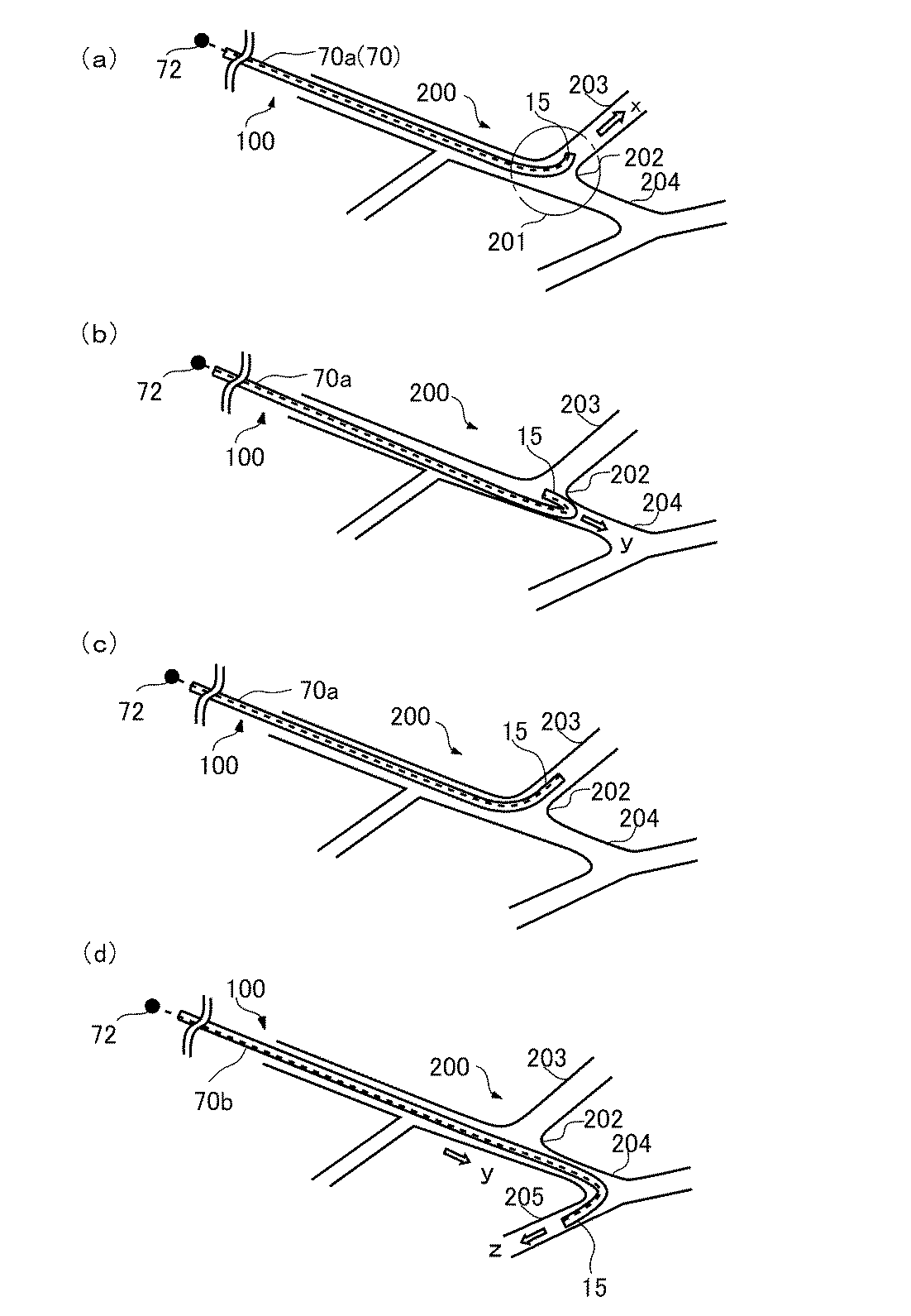
次に図6(a)〜(d)の模式図を用いて、本実施形態にかかるカテーテル100の使用状態の一例を説明する。図6(a)は、血管200内に挿通されたカテーテル100の遠位端側DEが、血管200の分岐部201に到達した状態を示している。ここで、分岐部201より血管枝203に向かって、図中の矢印の示す方向xにカテーテル100を進行させることを試みる。   Next, an example of the usage state of the catheter 100 according to the present embodiment will be described with reference to the schematic diagrams of FIGS. FIG. 6A shows a state in which the distal end DE of the catheter 100 inserted into the blood vessel 200 has reached the branching portion 201 of the blood vessel 200. Here, it is attempted to advance the catheter 100 in the direction x indicated by the arrow in the drawing from the branching portion 201 toward the blood vessel branch 203.

そこで、図6(a)に示すように、カテーテル100における操作線70の1本(第一操作線70a)の近位端72を牽引して、遠位端部15を方向xに曲率C1で屈曲させたとする。しかし、第一操作線70aを牽引した場合に、遠位端部15の曲率C1が血管枝203の分岐角度に適合していない場合、図6(b)に示すように、血管200のコーナー部202で遠位端部15が二つ折りに折れ曲がってしまう。かかる状態でカテーテル100を主管204に対して押し込むと、カテーテル100は主管204の延長線上にあたる方向yに進行してしまう場合がある。   Therefore, as shown in FIG. 6A, the proximal end 72 of one of the operation lines 70 (first operation line 70a) in the catheter 100 is pulled, and the distal end portion 15 is bent in the direction x with a curvature C1. Let it be bent. However, when the first operating line 70a is pulled, if the curvature C1 of the distal end portion 15 does not match the branch angle of the blood vessel branch 203, as shown in FIG. At 202, the distal end 15 is folded in half. When the catheter 100 is pushed into the main tube 204 in such a state, the catheter 100 may travel in the direction y corresponding to the extension line of the main tube 204.

ここで、血管枝203は、主管204に対して、曲率C1よりも小さな曲率で分岐しているとする。そこで、本実施形態のカテーテル100では、第一操作線70aの牽引量を調整することにより、図6(c)に示すように、血管枝203の分岐角度に適合した曲率で遠位端部15を屈曲させることができる。これにより、図6(c)に示すように、遠位端部15を血管枝203に対して十分に深く挿通することにより、カテーテル100の全体をこれに追随して進入させることができる。または、ハンドル部62に対する回転操作によってシース10の回転位相を調節し、第二操作線70bを牽引して曲率C2にて遠位端部15を屈曲させてもよい。   Here, it is assumed that the blood vessel branch 203 branches with respect to the main tube 204 with a curvature smaller than the curvature C1. Therefore, in the catheter 100 of the present embodiment, by adjusting the pulling amount of the first operation line 70a, as shown in FIG. 6C, the distal end portion 15 has a curvature adapted to the branch angle of the blood vessel branch 203. Can be bent. As a result, as shown in FIG. 6C, the distal end portion 15 is inserted sufficiently deep into the blood vessel branch 203, whereby the entire catheter 100 can be made to follow and enter. Alternatively, the rotational phase of the sheath 10 may be adjusted by a rotational operation on the handle portion 62, and the distal end portion 15 may be bent at the curvature C2 by pulling the second operation line 70b.

なお、いずれの操作線70を個別に牽引しても所望の曲率が達成されない場合には、他の操作線70を牽引して曲率を調整してもよい。より具体的には、第一操作線70aおよび第二操作線70bがシース10の径方向に180度対向配置されている本実施形態のカテーテル100の場合、二本の操作線70をともに牽引することにより、一本の操作線70のみを牽引した場合よりも、遠位端部15の曲率が減少する。これにより、操作者は、操作部70のスライダ64a、64bの牽引量を調整することにより、遠位端部15を所望の曲率で屈曲させることができる。   In addition, when a desired curvature is not achieved even if any operation line 70 is pulled individually, the curvature may be adjusted by pulling another operation line 70. More specifically, in the case of the catheter 100 of the present embodiment in which the first operation line 70a and the second operation line 70b are arranged to face each other by 180 degrees in the radial direction of the sheath 10, the two operation lines 70 are pulled together. Accordingly, the curvature of the distal end portion 15 is reduced as compared with the case where only one operation line 70 is pulled. Thereby, the operator can bend the distal end portion 15 with a desired curvature by adjusting the pulling amounts of the sliders 64 a and 64 b of the operation unit 70.

また、図5(d)に示すように、カテーテル100を、主管204から、血管枝203よりも大きな曲率で分岐する血管枝205に進入させる場合は、第二操作線70bを当該分岐方向にあわせた状態で近位端72を牽引するとよい。または、ハンドル部62に対する回転操作によってシース10の回転位相を調節して、第一操作線70aを牽引してもよい。また、第一操作線70aと第二操作線70bの双方を牽引して屈曲の微調整を行ってもよい。いずれの場合でも、カテーテル100の遠位端部15は好適な曲率で屈曲し、血管枝205に対して容易に進入させることができる。   Further, as shown in FIG. 5D, when the catheter 100 is advanced from the main tube 204 to the blood vessel branch 205 that branches with a curvature larger than that of the blood vessel branch 203, the second operation line 70b is aligned with the branch direction. The proximal end 72 may be pulled in a state where the Alternatively, the first operation line 70a may be pulled by adjusting the rotational phase of the sheath 10 by a rotational operation on the handle portion 62. Also, the fine adjustment of the bending may be performed by pulling both the first operation line 70a and the second operation line 70b. In either case, the distal end 15 of the catheter 100 bends with a suitable curvature and can be easily advanced into the vessel branch 205.

これにより、カテーテル100の全体の進行方向を、主管204の延在方向yから、血管枝205の延在方向zに変えることができる。そして、カテーテル100の遠位端部15を血管枝205に十分な深さで進入させることにより、遠位端部15に追随させてカテーテル100の全体を血管枝205に進入させることができる。   Accordingly, the entire traveling direction of the catheter 100 can be changed from the extending direction y of the main tube 204 to the extending direction z of the blood vessel branch 205. Then, by causing the distal end 15 of the catheter 100 to enter the vascular branch 205 at a sufficient depth, the entire catheter 100 can be advanced to the vascular branch 205 by following the distal end 15.

また、補強層30の存在により、遠位端部15を急角度で屈曲させても、メインルーメン20が潰れる、カテーテル100が二つ折りに折れ曲がる、などの問題が発生するのを防止することができる。そのため、メインルーメン20の内腔の平滑性を保持することができ、造影剤、薬液、内視鏡などを患部に円滑に供給することができる。   Further, the presence of the reinforcing layer 30 can prevent problems such as the main lumen 20 being collapsed and the catheter 100 being folded in two even if the distal end portion 15 is bent at a steep angle. . Therefore, the smoothness of the lumen of the main lumen 20 can be maintained, and a contrast medium, a drug solution, an endoscope, and the like can be smoothly supplied to the affected area.

以上が本実施形態にかかるカテーテル100の動作例である。ここで、補強層30を用いることにより、一般的には柔軟性が向上して屈曲性が優れるが、管材料に比べてトルク伝達性が低い。一方、管材料はトルク伝達性には優れるが、補強層30に比べ屈曲性に乏しい。しかし、本実施形態では、前述したように、補強層30を接合用部材90によって接合しているため、ねじり剛性/曲げ剛性の比が向上する。特に、接合部92が螺旋状で均一である。そのため、柔軟な屈曲性は損なうことなく、トルク伝達性にも優れたカテーテル100を実現することができ、さまざまな分岐角度で分岐する血管枝に対して本実施形態のカテーテル100を自在に進入させることができる。   The above is an operation example of the catheter 100 according to the present embodiment. Here, by using the reinforcing layer 30, the flexibility is generally improved and the flexibility is excellent, but the torque transmission is lower than that of the pipe material. On the other hand, the tube material is excellent in torque transmission, but is less flexible than the reinforcing layer 30. However, in this embodiment, as described above, since the reinforcing layer 30 is joined by the joining member 90, the ratio of torsional rigidity / bending rigidity is improved. In particular, the joint 92 is spiral and uniform. Therefore, the catheter 100 excellent in torque transmission can be realized without losing the flexible flexibility, and the catheter 100 of the present embodiment can freely enter the vascular branch that branches at various branch angles. be able to.

なお、本発明は上述の実施形態に限定されるものではなく、本発明の目的が達成される限りにおける種々の変形、改良等の態様も含む。   The present invention is not limited to the above-described embodiment, and includes various modifications and improvements as long as the object of the present invention is achieved.

たとえば、シース10の遠位端部15、近位端部16、その中間部の内層11または外層12を、それぞれ異なる樹脂材料111、112で形成し、それぞれの部位の剛性や屈曲性を変化させてもよい。また、補強層30の巻回ピッチを変えることにより、それぞれの部位の剛性や屈曲性を変化させてもよい。この場合、遠位端部15の補強層30の線材料31の巻回ピッチを広くすることにより、屈曲性が向上する。また、近位端部16は隣接する巻きが互いに密着するよう線材料31を巻回すれば、剛性が向上する。また、中間部は、遠位端部15の巻回ピッチよりも狭い巻回ピッチで線材料31を巻回することにより、遠位端部15の柔軟性と近位端部16の剛性との調和を図ることができる。このような構成とした上で、補強層30を接合することにより、各部位の屈曲性や剛性を損なうことなく、遠位端部15の屈曲を自在かつ円滑に行うことができる。また、メインルーメン20の平滑性も保つことができる。   For example, the distal end portion 15 and the proximal end portion 16 of the sheath 10 and the inner layer 11 or the outer layer 12 at the intermediate portion thereof are formed of different resin materials 111 and 112, respectively, and the rigidity and flexibility of each portion are changed. May be. Moreover, you may change the rigidity and flexibility of each site | part by changing the winding pitch of the reinforcement layer 30. FIG. In this case, the flexibility is improved by increasing the winding pitch of the wire material 31 of the reinforcing layer 30 of the distal end portion 15. Moreover, if the wire material 31 is wound around the proximal end portion 16 so that adjacent windings are in close contact with each other, the rigidity is improved. Further, the intermediate portion winds the wire material 31 at a winding pitch narrower than the winding pitch of the distal end portion 15, so that the flexibility of the distal end portion 15 and the rigidity of the proximal end portion 16 are reduced. Harmony can be achieved. With such a configuration, by joining the reinforcing layer 30, the distal end portion 15 can be bent freely and smoothly without impairing the flexibility and rigidity of each part. Further, the smoothness of the main lumen 20 can be maintained.

また、本実施形態では、シース10に二個のサブルーメン80(80a、80b)を180度間隔に対向して設けて、それぞれに操作線70(70a、70b)を挿通しているが、本発明がこれに限定されるものではない。シース10に三個以上のサブルーメン80を等角度間隔に設けてもよい。例えば、三個のサブルーメン80を等角度間隔(120度間隔)に設けた場合、補強層30も周方向に等角度間隔で3カ所、サブルーメン80の位置とは異なる位置(好ましくは、サブルーメン80間の中心位置)で形成することにより、3本の操作線70を操作することにより、トルク伝達性に優れ、しかも目的方向に微細な角度で遠位端部15を屈曲させることが可能となる。また、三個以上のサブルーメン80および3個以上の接合部92を周方向にランダムに設けてもよい。このように、ランダムに設けるとは、上記のように正確な等角度間隔に設けるのではなく、周方向に全体的に分散していれば、多少の角度のズレを生じてもよいという意味である。いずれの場合でも、任意の一本または二本以上の操作線70を選択して牽引することにより、当該操作線70の方向、または当該二本以上の操作線70の中間方向にシース10を屈曲させることができる。   Further, in this embodiment, two sub-lumens 80 (80a, 80b) are provided in the sheath 10 so as to face each other at an interval of 180 degrees, and the operation lines 70 (70a, 70b) are inserted into the sheath 10 respectively. The invention is not limited to this. Three or more sub-lumens 80 may be provided in the sheath 10 at equiangular intervals. For example, when three sub-lumens 80 are provided at equiangular intervals (120-degree intervals), the reinforcing layer 30 is also located at three positions at equal angular intervals in the circumferential direction (preferably, sub-lumen 80 positions are different). By forming the three operation lines 70, the distal end portion 15 can be bent at a fine angle in the target direction. It becomes. Further, three or more sub-lumens 80 and three or more joint portions 92 may be randomly provided in the circumferential direction. As described above, providing at random means that it is not provided at an exact equiangular interval as described above, but may cause a slight angle shift as long as it is dispersed in the circumferential direction as a whole. is there. In any case, the sheath 10 is bent in the direction of the operation line 70 or the intermediate direction of the two or more operation lines 70 by selecting and pulling any one or more operation lines 70. Can be made.

<第三実施形態>
次に、第三実施形態のカテーテルについて説明する。図7は、本実施形態にかかるカテーテル101の遠位端側DEの縦断面模式図であり、図8は図7のB−B線断面図である。また、図9は本実施形態にかかるシース10の内層11、補強層30および補強層30を接合する接合用部材90の遠位端側DEの斜視図である。なお、第二実施形態と同様な構成については、説明を省略する。
<Third embodiment>
Next, the catheter of the third embodiment will be described. FIG. 7 is a schematic longitudinal sectional view of the distal end DE of the catheter 101 according to the present embodiment, and FIG. 8 is a sectional view taken along line BB in FIG. FIG. 9 is a perspective view of the distal end DE of the joining member 90 that joins the inner layer 11, the reinforcing layer 30, and the reinforcing layer 30 of the sheath 10 according to the present embodiment. In addition, description is abbreviate | omitted about the structure similar to 2nd embodiment.

本実施形態のカテーテル101は、第二実施形態とほぼ同様の構成をしているが、補強層30を接合する接合用部材90が異なる。図7に示すように、本実施形態のカテーテル101は、管状本体(シース10)を有し、このシース10は、メインルーメン20と、樹脂材料111製の内層11と、線材料31が一六条、一定の巻回ピッチであって、隣接する巻き間に一定の間隙33を介して、螺旋状に巻回されて形成された補強層30と、補強層30の外周に、補強層30の線材料31とは逆方向であって、補強層30とは巻回ピッチも異なる螺旋状に線材料を一条巻回して形成した接合用部材90と、内層11の遠位端側DEに配置されたリング状のマーカ40と、樹脂材料112製の外層12と、この外層12内に、メインルーメン20の周囲に180度間隔で対向して配置された一対のサブルーメン80(80a、80b)と、外層12の外周に形成された樹脂材料51製のコート層50と、から構成されている。なお、接合用部材90の線材料の巻回ピッチは、前述したように補強層30とは異なるが、当該線材料の巻回ピッチは一定で、隣接する巻き間の間隙91も一定である。   The catheter 101 of the present embodiment has substantially the same configuration as that of the second embodiment, but the joining member 90 that joins the reinforcing layer 30 is different. As shown in FIG. 7, the catheter 101 of this embodiment has a tubular main body (sheath 10). The sheath 10 includes a main lumen 20, an inner layer 11 made of a resin material 111, and a wire material 31. The reinforcing layer 30 is formed by being spirally wound with a certain winding pitch between the adjacent windings with a constant gap 33 between the adjacent windings, and on the outer periphery of the reinforcing layer 30. The connecting member 90 is formed by winding a wire material in a spiral shape in a direction opposite to that of the wire material 31 and having a winding pitch different from that of the reinforcing layer 30 and the distal end DE of the inner layer 11. A ring-shaped marker 40, an outer layer 12 made of a resin material 112, and a pair of sub-lumens 80 (80a, 80b) disposed in the outer layer 12 so as to face each other around the main lumen 20 at an interval of 180 degrees. The resin material formed on the outer periphery of the outer layer 12 A coating layer 50 made of 51, and a. The winding pitch of the wire material of the joining member 90 is different from that of the reinforcing layer 30 as described above, but the winding pitch of the wire material is constant and the gap 91 between adjacent windings is also constant.

そして、補強層30の線材料31と、接合用部材90とが、螺旋状に規則的に接合部92により接合されている。この接合方法は、スポット溶接やはんだ付けなど、第二実施形態と同様の方法で行うことができる。以降の第四〜第九実施形態でも同様の方法を用いることができる。   The wire material 31 of the reinforcing layer 30 and the joining member 90 are regularly joined by the joining portion 92 in a spiral shape. This joining method can be performed by a method similar to that of the second embodiment, such as spot welding or soldering. The same method can be used in the following fourth to ninth embodiments.

そして、本実施形態のカテーテル101においても、図7、図8に示すように、第一操作線70aおよび第二操作線70bがそれぞれ挿通されたサブルーメン80a、80bが、補強層30の外側に対向して形成されている。本実施形態でも、接合部92により、トルク伝達性と屈曲性に優れたカテーテル101を得ることができる。   Also in the catheter 101 of the present embodiment, as shown in FIGS. 7 and 8, the sub-lumens 80 a and 80 b through which the first operation line 70 a and the second operation line 70 b are inserted are outside the reinforcing layer 30. They are formed to face each other. Also in this embodiment, the joint portion 92 can provide the catheter 101 having excellent torque transmission and flexibility.

<第四実施形態>
次に、第三実施形態のカテーテルについて説明する。図10は、本実施形態にかかるカテーテル102の遠位端側DEの縦断面模式図であり、図11は図10のC−C線断面図である。また、図12は本実施形態にかかるシース10の内層11、補強層30および補強層30を接合する接合用部材90の遠位端側DEの斜視図である。なお、第二、第三実施形態と同様な構成については、説明を省略する。
<Fourth embodiment>
Next, the catheter of the third embodiment will be described. FIG. 10 is a schematic longitudinal sectional view of the distal end DE of the catheter 102 according to this embodiment, and FIG. 11 is a sectional view taken along the line CC of FIG. FIG. 12 is a perspective view of the distal end DE of the joining member 90 that joins the inner layer 11, the reinforcing layer 30, and the reinforcing layer 30 of the sheath 10 according to the present embodiment. In addition, description is abbreviate | omitted about the structure similar to 2nd, 3rd embodiment.

本実施形態のカテーテル102は、第三実施形態とほぼ同様の構成をしているが、補強層30を接合する接合用部材90の線材料の本数が異なる。図10に示すように、本実施形態のカテーテル102は、管状本体(シース10)を有し、このシース10は、メインルーメン20と、樹脂材料111製の内層11と、線材料31が一六条、一定の巻回ピッチであって、隣接する巻き間に一定の間隙33を介して螺旋状に巻回されて形成された補強層30と、補強層30の外周に、補強層30の線材料31とは逆方向であって、巻回ピッチも異なる螺旋状に線材料を二条巻回して形成した接合用部材90と、内層11の遠位端側DEに配置されたリング状のマーカ40と、樹脂材料112製の外層12と、この外層12内に、メインルーメン20の周囲に180度間隔で対向して配置された一対のサブルーメン80(80a、80b)と、外層12の外周に形成された樹脂材料51製のコート層50と、から構成されている。なお、接合用部材90の二条の線材料の巻回開始位置が異なるが、互いの線材料の巻回ピッチは同一かつ一定であり、隣接する巻き間の間隙91も一定である。   The catheter 102 of the present embodiment has substantially the same configuration as that of the third embodiment, but the number of wire materials of the joining member 90 that joins the reinforcing layer 30 is different. As shown in FIG. 10, the catheter 102 of this embodiment has a tubular main body (sheath 10). The sheath 10 includes a main lumen 20, an inner layer 11 made of a resin material 111, and a wire material 31. The reinforcing layer 30 is formed by spirally winding with a constant gap 33 between adjacent windings, and a line of the reinforcing layer 30 on the outer periphery of the reinforcing layer 30. A joining member 90 formed by spirally winding a wire material in a direction opposite to that of the material 31 and having a different winding pitch, and a ring-shaped marker 40 disposed on the distal end DE of the inner layer 11 An outer layer 12 made of a resin material 112, a pair of sub-lumens 80 (80a, 80b) disposed in the outer layer 12 so as to face each other around the main lumen 20 at an interval of 180 degrees, and an outer periphery of the outer layer 12 The formed resin material 51 core The layer 50, and a. Although the winding start positions of the two strips of the wire material of the joining member 90 are different, the winding pitch of the mutual wire materials is the same and constant, and the gap 91 between adjacent windings is also constant.

そして、補強層30の線材料31と、二条の線材料からなる接合用部材90とが、螺旋状に規則的に接合部92により接合されている。そして、本実施形態のカテーテル102においても、図10、図11に示すように、第一操作線70aおよび第二操作線70bがそれぞれ挿通されたサブルーメン80a、80bが、補強層30の外側に対向して形成されている。本実施形態でも、接合部92により、トルク伝達性と屈曲性に優れたカテーテル102を得ることができる。   The wire material 31 of the reinforcing layer 30 and the joining member 90 made of two wire materials are regularly joined by the joining portion 92 in a spiral shape. Also in the catheter 102 of the present embodiment, as shown in FIGS. 10 and 11, the sub-lumens 80 a and 80 b through which the first operation line 70 a and the second operation line 70 b are inserted are outside the reinforcing layer 30. They are formed to face each other. Also in this embodiment, the joint portion 92 can provide the catheter 102 that is excellent in torque transmission and flexibility.

<第五実施形態>
次に、第五実施形態のカテーテルについて説明する。図13は、本実施形態にかかるカテーテル103の遠位端側DEの縦断面模式図であり、図14は図13のD−D線断面図である。また、図15は本実施形態にかかるシース10の内層11、補強層30および補強層30を接合する接合用部材90の遠位端側DEの斜視図である。なお、第二、第三実施形態と同様な構成については、説明を省略する。
<Fifth embodiment>
Next, the catheter of the fifth embodiment will be described. 13 is a schematic longitudinal sectional view of the distal end DE of the catheter 103 according to the present embodiment, and FIG. 14 is a sectional view taken along the line DD of FIG. FIG. 15 is a perspective view of the distal end DE of the joining member 90 that joins the inner layer 11, the reinforcing layer 30, and the reinforcing layer 30 of the sheath 10 according to the present embodiment. In addition, description is abbreviate | omitted about the structure similar to 2nd, 3rd embodiment.

本実施形態のカテーテル103は、第三実施形態とほぼ同様の構成をしているが、補強層30を接合する接合用部材90の線材料の本数が異なる。すなわち、図13に示すように、本実施形態のカテーテル103は、管状本体(シース10)を有し、このシース10は、メインルーメン20と、樹脂材料111製の内層11と、線材料31が一六条、一定の巻回ピッチであって、隣接する巻き間に一定の間隙33を介して螺旋状に巻回されて形成された補強層30と、補強層30の外周に、補強層30の線材料31とは逆方向であって、巻回ピッチ、および隣接する巻き間の間隙91も補強層30とは異なる螺旋状に線材料を四条巻回して形成した接合用部材90と、内層11の遠位端側DEに配置されたリング状のマーカ40と、樹脂材料112製の外層12と、この外層12内に、メインルーメン20の周囲に180度間隔で対向して配置された一対のサブルーメン80(80a、80b)と、外層12の外周に形成された樹脂材料51製のコート層50と、から構成されている。なお、本実施形態でも、接合用部材90の四条の線材料の巻回開始位置が異なるが、互いの巻回ピッチは同一かつ一定であり、隣接する巻き間の間隙91も一定である。本実施形態では、四条の線材料を多条巻きしているので、図14に示すように、周方向に異なる位置で4カ所、等間隔で接合部92が配置される。   The catheter 103 of the present embodiment has substantially the same configuration as that of the third embodiment, but the number of wire members of the joining member 90 that joins the reinforcing layer 30 is different. That is, as shown in FIG. 13, the catheter 103 of the present embodiment has a tubular main body (sheath 10). The sheath 10 includes a main lumen 20, an inner layer 11 made of a resin material 111, and a wire material 31. The reinforcing layer 30 is formed by spiral winding with a constant winding pitch between the adjacent windings with a constant gap 33 between the adjacent windings, and the reinforcing layer 30 on the outer periphery of the reinforcing layer 30. A joining member 90 formed by winding the wire material in four spirals in a direction opposite to the wire material 31 and having a winding pitch and a gap 91 between adjacent windings different from the reinforcing layer 30; 11, a ring-shaped marker 40 disposed on the distal end side DE, an outer layer 12 made of a resin material 112, and a pair disposed in the outer layer 12 so as to face each other around the main lumen 20 at an interval of 180 degrees. Sub-Bremen 80 (80a, 8 And b), a coating layer 50 made of a resin material 51 formed on the outer periphery of the outer layer 12, and a. Even in this embodiment, the winding start positions of the four strips of the wire 90 of the joining member 90 are different, but the winding pitch is the same and constant, and the gap 91 between adjacent windings is also constant. In the present embodiment, since the four strips of the wire material are wound in multiple lines, as shown in FIG. 14, the joint portions 92 are arranged at equal intervals at four positions at different positions in the circumferential direction.

そして、補強層30の線材料31と、四条の線材料からなる接合用部材90とが、螺旋状に規則的に接合部92により接合されている。そして、本実施形態のカテーテル103においても、図13、図14に示すように、第一操作線70aおよび第二操作線70bがそれぞれ挿通されたサブルーメン80a、80bが、補強層30の外側に対向して形成されている。本実施形態でも、接合部92により、トルク伝達性と屈曲性に優れたカテーテル103を得ることができる。   The wire material 31 of the reinforcing layer 30 and the joining member 90 made of the four wire materials are regularly joined by the joining portion 92 in a spiral shape. Also in the catheter 103 of the present embodiment, as shown in FIGS. 13 and 14, the sub-lumens 80 a and 80 b through which the first operation line 70 a and the second operation line 70 b are inserted are outside the reinforcing layer 30. They are formed to face each other. Also in this embodiment, the joint portion 92 makes it possible to obtain the catheter 103 with excellent torque transmission and flexibility.

<ねじり剛性、曲げ剛性等の実験例>
ここで、上記第二〜第五実施形態におけるカテーテル100〜103のねじり剛性、曲げ剛性、引張剛性、ねじり剛性/曲げ剛性の比、および、ねじり剛性/(曲げ剛性)2の比の各特性について計測実験を行った。なお、比較例として、図18に示すように、メインルーメン8を有する内層7の外周表面に、線材料3aを螺旋状に巻回して補強層3を形成したカテーテルについても同様の実験を行った。当該カテーテルの補強層3には、接合用部材を使用しておらず、かつ、補強層3の隣接する巻きも互いに接合していない。また、参考例として、図19に示すように、メインルーメン8を有する内層7の外周表面に、線材料3aを螺旋状に巻回して補強層3を形成し、当該補強層3に、直線状の接合用部材9を配置したカテーテルについても同様の実験を行った。当該カテーテルは、補強層3の外周に、軸方向に平行な直線状の接合用部材9を周方向に180度の角度で一対、対向して配置している。当該接合用部材9と補強層3とを、スポット溶接して溶接部9aを形成している。なお、上記第二〜第五実施形態におけるカテーテル100〜103では、補強層30を一六条で形成しているが、本計測実験で使用したすべてのカテーテルは、補強層30を八条で形成したものを使用している。なお、リング状の接合用部材90や線材料製の接合用部材90の条数や接合方法は、各実施形態と同様である。
<Examples of torsional rigidity, bending rigidity, etc.>
Here, regarding the respective characteristics of the torsional rigidity, bending rigidity, tensile rigidity, torsional rigidity / bending rigidity ratio, and torsional rigidity / (bending rigidity) 2 ratio of the catheters 100 to 103 in the second to fifth embodiments. A measurement experiment was conducted. As a comparative example, as shown in FIG. 18, a similar experiment was performed on a catheter in which the reinforcing layer 3 was formed by spirally winding the wire material 3 a around the outer peripheral surface of the inner layer 7 having the main lumen 8. . No joining member is used for the reinforcing layer 3 of the catheter, and adjacent windings of the reinforcing layer 3 are not joined to each other. As a reference example, as shown in FIG. 19, the reinforcing material 3 is spirally wound around the outer peripheral surface of the inner layer 7 having the main lumen 8 to form the reinforcing layer 3. The same experiment was conducted on the catheter in which the joining member 9 was arranged. In the catheter, a pair of linear joining members 9 parallel to the axial direction are arranged on the outer periphery of the reinforcing layer 3 so as to face each other at an angle of 180 degrees in the circumferential direction. The joining member 9 and the reinforcing layer 3 are spot welded to form a welded portion 9a. In addition, in the catheters 100 to 103 in the second to fifth embodiments, the reinforcing layer 30 is formed by 16 lines, but all the catheters used in this measurement experiment have the reinforcing layer 30 formed by 8 lines. I am using something. In addition, the number of strips and the joining method of the ring-shaped joining member 90 and the joining member 90 made of a wire material are the same as those in each embodiment.

なお、実験に用いた補強層30の線材料31および接合用部材90として用いた線材料の特性は、以下に示すとおりである。
(1)補強層の線材料
・線材料直径:0.1mm
・巻き数:八条
・内径:0.6mm
・中心軸とのなす角度θ:45度
・ヤング率:200GPa
・ポアソン比:0.3
(2)接合用部材の線材料
・中心軸とのなす角度以外は、上記補強層の線材料と同様のものを使用した。
The characteristics of the wire material 31 of the reinforcing layer 30 used in the experiment and the wire material used as the joining member 90 are as shown below.
(1) Wire material of reinforcing layer Wire material diameter: 0.1 mm
・ Number of windings: Hachijo ・ Inner diameter: 0.6 mm
・ Angle θ with the central axis: 45 degrees ・ Young's modulus: 200 GPa
-Poisson's ratio: 0.3
(2) Wire material of joining member-The same wire material as that of the reinforcing layer was used except for the angle formed with the central axis.

次に、解析方法を説明する。コンピュータシステムのANSYS(Ver.12.0)を用い、BEAM189要素(はり要素)で、スポット溶接箇所を短い線材料でモデル化した。ねじり、曲げ、引張の仮想的な試験で、剛性を算出した。その算出結果を、以下の表1に示す。   Next, an analysis method will be described. Using a computer system ANSYS (Ver. 12.0), a spot welded part was modeled with a short wire material using a BEAM189 element (beam element). Rigidity was calculated by virtual tests of torsion, bending and tension. The calculation results are shown in Table 1 below.

Figure 2012147956
Figure 2012147956

以上の実験で、第二〜第五実施形態のカテーテル100〜103では、補強層30を接合用部材90によって螺旋状にスポット接合しているため、直線的に接合した参考例や何ら接合のない比較例に比べ、ねじり剛性/曲げ剛性の比もねじり剛性/(曲げ剛性)2の比も、ともに向上することが判明した。いずれの実施形態においても、柔軟な屈曲性は損なうことなく、トルク伝達性にも優れたカテーテル100〜103を実現することができる。したがって、第一操作線70aおよび第二操作線70bを操作することにより、さまざまな分岐角度で分岐する血管枝に対して各実施形態のカテーテル100〜103を自在に進入させることができる。特に、第三、および、第四実施形態のカテーテル101、102は、ねじり剛性/曲げ剛性の比が2.5以上で、かつ、ねじり剛性/(曲げ剛性)2の比が0.2以上であるため、優れた屈曲性とトルク伝達性を有し、最も好ましいということが判明した。 In the above experiments, in the catheters 100 to 103 according to the second to fifth embodiments, the reinforcing layer 30 is spot-bonded spirally by the bonding member 90, so there is no reference example in which the reinforcing layer 30 is linearly bonded or any bonding. It was found that both the ratio of torsional rigidity / bending rigidity and the ratio of torsional rigidity / (bending rigidity) 2 were improved as compared with the comparative example. In any embodiment, the catheters 100 to 103 excellent in torque transmission can be realized without losing the flexible flexibility. Therefore, by operating the first operation line 70a and the second operation line 70b, the catheters 100 to 103 of each embodiment can freely enter the vascular branches that branch at various branch angles. In particular, the catheters 101 and 102 of the third and fourth embodiments have a torsional rigidity / bending rigidity ratio of 2.5 or more and a torsional rigidity / (bending rigidity) 2 ratio of 0.2 or more. Therefore, it has been found that it has excellent flexibility and torque transmission and is most preferable.

なお、上記第三〜第五実施形態では、線材料製の接合用部材90の巻回方向を、補強層30の線材料31や板部材の形成方向と異なる方向に形成していたが、本発明がこれに限定されるものではない。例えば、同一方向に巻回してもよい。この場合、補強層30の外周に、螺旋の巻回ピッチを変えるだけで、同一方向で線材料を巻回せばよいので、巻回用装置の設定等を効率的に行うことができる。また、螺旋方向が同一方向であるため、互いを接合した際に、トルク性は向上しながらも、円滑な屈曲が可能となる。   In the third to fifth embodiments, the winding direction of the joining member 90 made of the wire material is formed in a direction different from the formation direction of the wire material 31 and the plate member of the reinforcing layer 30. The invention is not limited to this. For example, you may wind in the same direction. In this case, the wire material may be wound in the same direction only by changing the spiral winding pitch on the outer periphery of the reinforcing layer 30, so that the setting of the winding device and the like can be performed efficiently. Moreover, since the spiral direction is the same direction, when the two are joined together, smooth bending is possible while improving the torque characteristics.

<第六実施形態>
次に、第六実施形態のカテーテルについて説明する。図16(a)は、本実施形態にかかるカテーテル104の補強層30に用いる母材としての管材料30aである。なお、この管材料30aは、以降で説明する第七、第八実施形態でも同様のものを用いている。
<Sixth embodiment>
Next, the catheter of the sixth embodiment will be described. FIG. 16A shows a tube material 30a as a base material used for the reinforcing layer 30 of the catheter 104 according to this embodiment. The same pipe material 30a is used in the seventh and eighth embodiments described below.

本実施形態のカテーテル104では、上記管材料30aに、図16(b)に示すように、内層11の長手方向の中心軸とのなす角度が45度となるよう、8本の螺旋状の切込み部32を形成している。これにより、断面形状が長方形の線材料31により、八条の多条巻きの螺旋状の補強層30を形成している。そして、このように形成した補強層30の隣接する巻きを互いにスポット溶接やはんだ付けすることで、接合部92を形成してもよい。しかし、本実施形態では、補強層30の外周に、図17(a)に示すように、接合用部材90の母材としての管材料90aを配置し、図17(b)に示すように、当該管材料90aを所定間隙91で螺旋状に切欠いて切欠き部93を形成し、線材状の接合用部材90を形成している。そして、この接合用部材90と補強層30とを、規則的な螺旋状にスポット溶接やはんだ付けして、接合部92を介して接合する。なお、線材料状の接合用部材90と補強層30との接合は、螺旋状に限らず、隣接する接合部92が互いに長尺方向に一直線上にならなければ、螺旋状以外の規則的な接合であってもよい。または、ランダムな接合であってもよい。このような形成により、補強層30が多層のカテーテルを得ることができる。また、この多層の接合により、ねじり剛性/曲げ剛性比が向上し、トルク伝達性に優れたカテーテル104を得ることができる。   In the catheter 104 of the present embodiment, eight spiral cuts are made in the tube material 30a as shown in FIG. 16 (b) so that the angle formed with the central axis in the longitudinal direction of the inner layer 11 is 45 degrees. A portion 32 is formed. Thereby, the eight-row multi-strand spiral reinforcing layer 30 is formed by the wire material 31 having a rectangular cross-sectional shape. Then, the joining portion 92 may be formed by spot welding or soldering the adjacent windings of the reinforcing layer 30 thus formed. However, in the present embodiment, a pipe material 90a as a base material of the joining member 90 is arranged on the outer periphery of the reinforcing layer 30 as shown in FIG. 17A, and as shown in FIG. The tube material 90a is spirally cut out at a predetermined gap 91 to form a cutout portion 93, thereby forming a wire-like joining member 90. Then, the joining member 90 and the reinforcing layer 30 are spot-welded or soldered in a regular spiral shape and joined via the joining portion 92. Note that the joining of the wire-material-like joining member 90 and the reinforcing layer 30 is not limited to a spiral shape, and other than the spiral shape if adjacent joining portions 92 are not aligned with each other in the longitudinal direction. Bonding may be used. Alternatively, random bonding may be used. With this formation, a catheter having a multilayered reinforcing layer 30 can be obtained. In addition, this multi-layer joining improves the torsional rigidity / bending rigidity ratio, and the catheter 104 having excellent torque transmission can be obtained.

なお、本実施形態では、8本の螺旋状の切込み部32を形成し、八条巻きの補強層30としているが、本発明がこれに限定されるものではない。例えば、1本螺旋状の切込み部32として一条巻きの補強層30としてもよいし、8本に限らず、2本以上の複数本の螺旋状の切込み部32を形成することで形成した補強層30も、多条巻きに含まれるものとする。また、本実施形態の補強層30も螺旋状であるため、図示はしないが、線材料31を長手方向に、異なる間隙33で延伸させて、隣接する巻き間の密着度(すなわち、各間隙33)を変化させることができる。したがって、例えば、カテーテル104の近位端側CEは線材料31同士を密に配置することで剛性を保持し、遠位端側DEは線材料31を延伸して隣接する巻き間に間隙33を形成して固定してもよく、カテーテル104の遠位端側に良好な屈曲性を持たせることができる。また、この隣接する巻き間の間隙33も、部位によって異なる広さとすることで、屈曲性を変化させることが可能となる。そのため、操作線70の牽引により、カテーテルの遠位端側DEの屈曲方向や屈曲角度の調整を柔軟に行うことが可能となる。   In the present embodiment, eight spiral cut portions 32 are formed to form the eight-strand reinforcing layer 30, but the present invention is not limited to this. For example, a single-strand reinforcing layer 30 may be used as the single spiral cut portion 32, and the reinforcing layer 30 is not limited to eight but formed by forming two or more spiral cut portions 32. 30 is also included in the multiple winding. In addition, since the reinforcing layer 30 of the present embodiment is also spiral, although not shown, the wire material 31 is stretched in the longitudinal direction with different gaps 33, and the degree of adhesion between adjacent windings (that is, each gap 33). ) Can be changed. Therefore, for example, the proximal end CE of the catheter 104 maintains rigidity by arranging the wire materials 31 densely, and the distal end DE extends the wire material 31 to form a gap 33 between adjacent windings. It may be formed and fixed, and the distal end side of the catheter 104 can have good flexibility. In addition, it is possible to change the flexibility by setting the gap 33 between the adjacent windings to have different widths depending on the part. Therefore, by pulling the operation line 70, the bending direction and the bending angle of the distal end side DE of the catheter can be flexibly adjusted.

<第七実施形態>
次に、第七実施形態のカテーテルについて説明する。図16(c)に示すように、本実施形態のカテーテル105は、紙面の上下方向から、切残し部36を有するように、軸方向に対して45度(θ)の傾斜で互い違いに切込み部32を形成している。このような切込み部32により、線材よりも扁平で広幅の線材料31によって、全体が一部で連結し、長手方向に伸縮および屈曲が可能な補強層30が形成される。このような補強層30であっても、接合により、ねじり剛性/曲げ剛性比が向上し、トルク伝達性に優れたカテーテル105を得ることができる。また、本実施形態では、切残し部36で補強層30が連結されているので、接合部92の役割も果たすものとなる。さらに、補強層30の隣接する巻きを互いにスポット溶接やはんだ付けすることで、接合部92を形成してもよい。また、当該補強層30の外周に、さらに接合用部材90を配置して、補強層30と接合用部材90とを接合して、接合部92を形成した、多層構造の補強層30としてもよい。
<Seventh embodiment>
Next, the catheter of the seventh embodiment will be described. As shown in FIG. 16 (c), the catheter 105 of the present embodiment is alternately cut at 45 degrees (θ) with respect to the axial direction so as to have uncut portions 36 from the vertical direction of the drawing. 32 is formed. By such a cut portion 32, a reinforcing layer 30 that is flattened and wider than the wire and is partially connected as a whole and can be expanded and contracted in the longitudinal direction is formed. Even with such a reinforcing layer 30, the torsional rigidity / bending rigidity ratio is improved by joining, and the catheter 105 having excellent torque transmission can be obtained. In the present embodiment, since the reinforcing layer 30 is connected by the uncut portion 36, the role of the joint portion 92 is also achieved. Further, the joint 92 may be formed by spot welding or soldering adjacent windings of the reinforcing layer 30 to each other. Further, a multi-layered reinforcing layer 30 in which a joining member 90 is further arranged on the outer periphery of the reinforcing layer 30 and the reinforcing layer 30 and the joining member 90 are joined to form a joining portion 92 may be used. .

また、本実施形態の補強層30も隣接する巻き間の間隙33を変えて自在に伸縮できる形状である。そのため、管材料30aへ切込み部32を入れて線材料31を形成した後に、第六実施形態等と同様に、図16(d)に示すように、線材料31を長手方向に、異なる間隙33で延伸させて、隣接する巻き間の密着度(すなわち、各間隙33)を変化させることができる。例えば、カテーテル105の近位端側CEは線材料31に間隙33を介さず密にすることで(図示せず)良好な剛性を保持する。一方、図16(d)に示すように、遠位端側DEでは内層11の長手方向に線材料31を延伸して隣接する巻き間の間隙33を広幅に形成すれば、遠位端側DEに良好な屈曲性を持たせることができる。そのため、操作線70の牽引により、カテーテル105の遠位端部15の屈曲方向や屈曲角度の調整を柔軟に行うことが可能となる。また、遠位端側DEの隣接する巻き間の間隙33も、部位によって異なる幅とすることで、屈曲性を変化させることが可能となる。例えば、遠位端側DEの最も先端側の隣接する巻き間の間隙33を狭くするか間隙33を介さずに密着させ、先端以外の遠位端側DEは隣接する巻き間に適宜の間隙33を設けて補強層30を形成することにより、先端の剛性が向上し、体腔内への先端の挿通や進行を容易に行うことも可能となる。そして、挿通後は、カテーテルの遠位端部15の自在な屈曲性やトルク伝達性を得ることができる。   Further, the reinforcing layer 30 of the present embodiment also has a shape that can freely expand and contract by changing the gap 33 between adjacent windings. Therefore, after forming the wire material 31 by inserting the cut portion 32 into the tube material 30a, as shown in FIG. 16 (d), the wire material 31 is placed in the longitudinal direction with a different gap 33 as in the sixth embodiment. The degree of adhesion between adjacent windings (that is, each gap 33) can be changed. For example, the proximal end CE of the catheter 105 maintains good rigidity (not shown) by being close to the wire material 31 without the gap 33 (not shown). On the other hand, as shown in FIG. 16D, if the wire material 31 is stretched in the longitudinal direction of the inner layer 11 to form a wide gap 33 between adjacent windings on the distal end side DE, the distal end side DE Can have good flexibility. Therefore, the bending direction and the bending angle of the distal end portion 15 of the catheter 105 can be adjusted flexibly by pulling the operation line 70. In addition, the gap 33 between adjacent windings on the distal end side DE can also be changed in flexibility by changing the width depending on the part. For example, the gap 33 between adjacent windings on the most distal end side of the distal end side DE is narrowed or closely contacted without the gap 33, and the distal end DE other than the tip has an appropriate gap 33 between adjacent windings. By forming the reinforcing layer 30 by providing the above, the rigidity of the tip is improved, and it is possible to easily insert and advance the tip into the body cavity. And after insertion, the flexibility of the distal end part 15 of a catheter and the torque transmission nature can be acquired.

<第八実施形態>
次に、第八実施形態のカテーテルについて説明する。図16(e)に示すように、本実施形態のカテーテル106は、図16(a)に示す管材料30aに、一定間隙33を介して、内層11の長手方向の中心軸とのなす角度が45度(θ)となるよう、切残し部36を残して紙面上下方向から交互に切欠いている。これにより、複数の切欠き部34が設けられ、かつ、切残し部36により連結された、扁平で間隙33が広幅な線材料31製の補強層30を形成している。したがって、本実施形態でも、切残し部36が、接合部92の役目を果たすものとなる。また、図16(f)は、図16(e)をX−X線方向から観察した状態の模式図である。
<Eighth embodiment>
Next, the catheter of the eighth embodiment will be described. As shown in FIG. 16 (e), the catheter 106 of the present embodiment has an angle formed between the tube material 30 a shown in FIG. 16 (a) and the central axis in the longitudinal direction of the inner layer 11 via the constant gap 33. In order to be 45 degrees (θ), the cutout portions 36 are alternately cut away from the up and down direction of the paper, leaving the uncut portions 36. As a result, a reinforcing layer 30 made of a wire material 31 having a plurality of notches 34 and connected by uncut portions 36 and having a flat width and a wide gap 33 is formed. Therefore, also in this embodiment, the uncut portion 36 serves as the joint portion 92. Moreover, FIG.16 (f) is a schematic diagram of the state which observed FIG.16 (e) from the XX line direction.

そして、第八実施形態の変形例として、このような補強層30の外周に、さらに、図17(c)、(d)に示すように接合用部材90の母材となる管材料90aを配置する。次に、図17(e)に示すように、補強層30の切欠き方向とは異なる方向と間隙91(ただし間隙91は一定)を介し、かつ、切残し部94を残して管材料90aを切欠いて複数の切欠き部93を形成している。これにより、切残し部94により連結された平板状の接合用部材90を形成している。そして、この接合用部材90と補強層30とを、螺旋状またはその他の規則的若しくは不規則的であって、隣接する接合部92同士が一直線上にならないように、スポット溶接または、はんだ付けなどにより接合している。このような多層構造の補強層30であっても、接合用部材90との接合により、補強層30の隣接する巻き間の間隙33を変化させた場合に、その間隙33を保持することができる。さらには、ねじり剛性/曲げ剛性比が向上し、トルク伝達性に優れたカテーテル106を得ることができる。   As a modification of the eighth embodiment, a pipe material 90a that is a base material of the joining member 90 is further disposed on the outer periphery of the reinforcing layer 30 as shown in FIGS. 17 (c) and 17 (d). To do. Next, as shown in FIG. 17 (e), the tube material 90 a is passed through a direction different from the notch direction of the reinforcing layer 30 and a gap 91 (however, the gap 91 is constant) and leaving a notch 94. A plurality of notches 93 are formed by notching. Thereby, the flat plate-shaped joining member 90 connected by the uncut portion 94 is formed. Then, the welding member 90 and the reinforcing layer 30 are spirally welded or other regular or irregular, and spot welding, soldering, or the like so that the adjacent joints 92 are not aligned with each other. Are joined together. Even in the case of the reinforcing layer 30 having such a multilayer structure, when the gap 33 between adjacent windings of the reinforcing layer 30 is changed by joining with the joining member 90, the gap 33 can be maintained. . Furthermore, the torsional rigidity / bending rigidity ratio is improved, and the catheter 106 having excellent torque transmission can be obtained.

なお、本実施形態では、接合用部材90の切欠き部93を、補強層30と異なる方向で、かつ一定の間隙91を介して切欠き部93を形成している。しかし、本実施形態がこれに限定されるものではなく、補強層30と同一方向であるが、補強層30の間隙33とは異なる隣接する巻き間の間隙91を介して接合用部材90を形成してもよい。また、隣接する巻き間に不規則な間隙91を介して切欠き部93を形成してもよく、隣接する巻き間の間隙91の広さに応じて屈曲性などを変化させることも可能である。また、接合用部材90の場合は、必ずしも切残し部94を残して切欠く必要はなく、所定間隙ごとに、切り離してもよく、切残し部94のない部分は、屈曲性が向上可能である。また、切残し部94を設けずに、一定または所定間隙91を介して切欠いて、リング状の接合用部材90としてもよい。または、管材料90aに螺旋状の切欠きを1本または複数本形成したものも、一条または多条巻きの接合用部材90に含むものとする。このような切欠きにより形成した接合用部材90を、螺旋状の補強層30と接合することにより、軸方向への伸縮が自在となり、例えば、補強層30の隣接する巻き間の間隙33を、カテーテルの部位に応じて異なる広さとした場合に、この間隙33の広さに追随して接合用部材90の隣接する巻き間の間隙91を異なる広さに調整することができる。したがって、接合用部材90との接合によるトルク伝達性を損なうことなく、より屈曲性が向上したカテーテルを得ることが可能となる。   In the present embodiment, the notch 93 of the joining member 90 is formed in a direction different from that of the reinforcing layer 30 and through a certain gap 91. However, the present embodiment is not limited to this, and the joining member 90 is formed through a gap 91 between adjacent windings that is in the same direction as the reinforcing layer 30 but is different from the gap 33 of the reinforcing layer 30. May be. Further, the notch 93 may be formed between the adjacent windings via the irregular gap 91, and the flexibility or the like can be changed according to the width of the gap 91 between the adjacent windings. . Further, in the case of the joining member 90, it is not always necessary to leave the cut-out portion 94, and the cut-out portion 94 may be cut off at every predetermined gap, and the portion without the cut-off portion 94 can be improved in flexibility. . In addition, the ring-shaped joining member 90 may be formed by notching through the fixed gap 91 without providing the uncut portion 94. Alternatively, one or a plurality of spiral cutouts formed in the tube material 90a are included in the single or multi-strand joint member 90. By joining the joining member 90 formed by such a notch to the spiral reinforcing layer 30, it is possible to expand and contract in the axial direction. For example, the gap 33 between adjacent windings of the reinforcing layer 30 is When the width varies depending on the catheter site, the gap 91 between adjacent windings of the bonding member 90 can be adjusted to a different width following the width of the gap 33. Therefore, it is possible to obtain a catheter with improved flexibility without impairing torque transmission by joining with the joining member 90.

なお、上記第六〜第八実施形態では、補強層30用の管材料30aを内層11の外周に配置してから切込み部32や切欠き部34を形成している。次に、このような補強層30の隣接する巻き同士を、はんだ付けして接合部92を複数個形成している。これら複数の接合部92は、補強層の長手方向に配置され、かつ、周方向においては互いに異なる位置になるように配置されている。または、補強層30の外周に接合用部材90用の管材料90aを配置してから、この管材料90aに切込み部(図示せず)や切欠き部93を形成して接合用部材90を得て、この接合用部材90と補強層30とを、スポット溶接や、はんだ付け等により接合している。しかし、本発明がこれに限定されるものではない。例えば、管材料30a、90aに、それぞれ切込み部32や切欠き部34、93を形成して補強層30や接合用部材90を形成した後、内層11の外周に補強層30、接合用部材90を順次配置して、接合してもよい。または、補強層30と接合用部材90とを接合した後に、これらを内層11の外周に配置してもよい。   In the sixth to eighth embodiments, the notch 32 and the notch 34 are formed after the pipe material 30 a for the reinforcing layer 30 is arranged on the outer periphery of the inner layer 11. Next, adjacent windings of such a reinforcing layer 30 are soldered to form a plurality of joint portions 92. The plurality of joint portions 92 are arranged in the longitudinal direction of the reinforcing layer and arranged at different positions in the circumferential direction. Alternatively, after the pipe material 90a for the joining member 90 is disposed on the outer periphery of the reinforcing layer 30, a notch (not shown) or a notch 93 is formed in the pipe material 90a to obtain the joining member 90. The joining member 90 and the reinforcing layer 30 are joined by spot welding, soldering, or the like. However, the present invention is not limited to this. For example, after forming the notch 32 and the notches 34 and 93 in the pipe materials 30 a and 90 a to form the reinforcing layer 30 and the joining member 90, the reinforcing layer 30 and the joining member 90 are formed on the outer periphery of the inner layer 11. May be sequentially arranged and joined. Alternatively, after the reinforcing layer 30 and the joining member 90 are joined, they may be disposed on the outer periphery of the inner layer 11.

また、上記各実施例では、少なくとも遠位端側DEにおいて線材料31を、隣接する巻き間に所定の間隙33を介して巻回層(補強層30)を形成し、その外周に配置したリング状、または螺旋状に形成し、接合用部材90と接合している。または、第一実施形態のように、接合用部材90を用いずにスポット溶接により巻回層30の隣接する巻き同士を接合している。しかし、本発明がこれに限定されるものではなく、接合用部材90としてはんだを用いてもよい。例えば、遠位端側DEまで、隣接する線材料31が互いに密着するよう巻回して巻回層30を形成し、密着して隣接する線材料31の巻き同士を一カ所以上、はんだ付け等により接合する。この場合、はんだが接合用部材90となる。この場合、リングや線材料の配置作業や巻回層30との接合作業を省くこともでき、より簡易な構成とすることができる。また、隣接する巻き同士を、例えば、図1(c)のように長手方向に螺旋状に規則的に接合してもよいし、他の異なる実施形態として、長手方向に不規則に接合してもよい。これらのような構成でも、屈曲性とトルク伝達性とに優れたカテーテルを、より簡易に得ることができる。   Further, in each of the above embodiments, the wire material 31 is formed at least on the distal end side DE with the winding layer (reinforcing layer 30) formed between the adjacent windings via a predetermined gap 33, and is arranged on the outer periphery thereof. It is formed in a shape or a spiral shape and joined to the joining member 90. Alternatively, as in the first embodiment, adjacent windings of the winding layer 30 are joined by spot welding without using the joining member 90. However, the present invention is not limited to this, and solder may be used as the joining member 90. For example, the winding layer 30 is formed by winding the adjacent wire materials 31 in close contact with each other up to the distal end DE, and the winding of the adjacent wire materials 31 in close contact with each other is performed by soldering or the like. Join. In this case, the solder becomes the bonding member 90. In this case, the arrangement work of the ring and the wire material and the joining work with the wound layer 30 can be omitted, and a simpler configuration can be obtained. Further, adjacent windings may be regularly joined spirally in the longitudinal direction as shown in FIG. 1C, for example, and may be joined irregularly in the longitudinal direction as another different embodiment. Also good. Even with such a configuration, a catheter excellent in flexibility and torque transmission can be obtained more easily.

また、上記各実施形態は、ガイドワイヤおよびカテーテルについて実施しているが、本発明は上述の実施形態に限定されるものではなく、内視鏡、超音波器具など、体腔内に挿入して使用する、他の長尺な医療機器にも適用することができる。   Moreover, although each said embodiment is implemented about the guide wire and the catheter, this invention is not limited to the above-mentioned embodiment, It uses by inserting in body cavities, such as an endoscope and an ultrasonic instrument. It can also be applied to other long medical devices.

1 ガイドワイヤ(医療機器)
10 管状本体(シース)
11 内層
111 樹脂材料
12 外層
112 樹脂材料
15 遠位端部
16 近位端部
20 メインルーメン
30 補強層(巻回層)
30a 管材料
31 線材料
32 切込み部(切込み)
33、33a 間隙
34 切欠き部(切欠き)
40 マーカ
90 接合用部材
90a 管材料
91 間隙
92 接合部
93 切欠き部(切欠き)
100、101、102、103、104、105、106 カテーテル(医療機器)
C,C1,C2 曲率
DE 遠位端側
CE 近位端側
PE 近位端側
1 Guidewire (medical equipment)
10 Tubular body (sheath)
DESCRIPTION OF SYMBOLS 11 Inner layer 111 Resin material 12 Outer layer 112 Resin material 15 Distal end part 16 Proximal end part 20 Main lumen 30 Reinforcement layer (winding layer)
30a Tube material 31 Wire material 32 Cut section (cut)
33, 33a Gap 34 Notch (notch)
40 Marker 90 Joining member 90a Tube material 91 Gap 92 Joining portion 93 Notch (notch)
100, 101, 102, 103, 104, 105, 106 Catheter (medical device)
C, C1, C2 Curvature DE Distal end side CE Proximal end side PE Proximal end side

Claims (19)

体腔内に挿入して用いられ、前記体腔内の形状に追随して形状を変化させる長尺の医療機器であって、
長手方向に延在して、巻回形成された巻回層が形成され、
巻回形成された前記巻回層の巻き同士の少なくとも一部が接合されて、複数の接合部が形成され、
複数の前記接合部が、前記巻回層の長手方向に存在し、
当該複数の前記接合部のうち、前記巻回層の長手方向において隣接する前記接合部が、周方向に対して互いに異なる位置に配置されていることを特徴とする医療機器。
A long medical device that is inserted into a body cavity and used to change the shape following the shape in the body cavity,
Extending in the longitudinal direction, a wound layer formed by winding is formed,
At least a part of the windings of the winding layer formed by winding is bonded to form a plurality of bonding portions,
A plurality of the joints are present in the longitudinal direction of the wound layer;
Among the plurality of joints, the joints adjacent in the longitudinal direction of the wound layer are arranged at different positions with respect to the circumferential direction.
前記巻回層は、複数本の線材料を多条巻きすることで巻回形成されたことを特徴とする請求項1に記載の医療機器。   The medical device according to claim 1, wherein the wound layer is formed by winding a plurality of wire materials in a multi-winding manner. 前記巻回層の前記接合部は、隣接する前記巻き同士が互いにスポット溶接されることにより接合されたことを特徴とする請求項1または2に記載の医療機器。   The medical device according to claim 1 or 2, wherein the joint portion of the wound layer is joined by spot welding the adjacent windings to each other. 前記巻回層は、複数の前記接合部が、周回方向に対して螺旋状に配置されていることを特徴とする請求項1から3のいずれか一項に記載の医療機器。   The medical device according to any one of claims 1 to 3, wherein the wound layer includes a plurality of the joint portions arranged in a spiral shape with respect to a circumferential direction. 前記巻回層は、隣接する前記巻き同士が密着して巻回形成され、
当該密着して隣接する前記巻き同士が少なくとも一カ所で接合され、当該密着して隣接する前記巻き同士の前記接合部が、前記巻回層の長手方向に複数存在し、かつ、当該巻回層の周方向に対して互いに異なる位置に配置されていることを特徴とする請求項1から4のいずれか一項に記載の医療機器。
The winding layer is formed by closely winding the adjacent windings,
The tightly adjacent windings are joined at at least one location, and there are a plurality of the joining portions of the closely adjacent windings in the longitudinal direction of the wound layer, and the wound layer The medical device according to any one of claims 1 to 4, wherein the medical devices are arranged at positions different from each other in the circumferential direction.
前記巻回層の複数の前記接合部は、周方向に少なくとも3カ所以上、等間隔で異なる位置に配置されている請求項1から5のいずれか一項に記載の医療機器。   The medical device according to any one of claims 1 to 5, wherein the plurality of joint portions of the wound layer are disposed at different positions at equal intervals in at least three locations in the circumferential direction. 前記巻回層の複数の前記接合部は、周方向に少なくとも3カ所以上、ランダムに配置されている請求項1から5のいずれか一項に記載の医療機器。   The medical device according to any one of claims 1 to 5, wherein a plurality of the joint portions of the wound layer are randomly arranged in at least three locations in the circumferential direction. 前記巻回層は、前記巻回層の巻回方向とは異なる方向に、巻回形成された接合用部材をさらに有し、前記巻回層と前記接合用部材との互いの当接部分の少なくとも一部が接合されて前記接合部が形成されていることを特徴とする請求項1から7のいずれか一項に記載の医療機器。   The winding layer further includes a joining member that is wound in a direction different from the winding direction of the winding layer, and the winding layer and the joining member are in contact with each other. The medical device according to claim 1, wherein at least a part is joined to form the joint. 前記巻回層は、前記巻回層の巻回方向と同一の方向であって、当該巻回層とは異なる巻回ピッチで巻回形成された接合用部材をさらに有し、前記巻回層と前記接合用部材との互いの当接部分の少なくとも一部が接合されて前記接合部が形成されていることを特徴とする請求項1から7のいずれか一項に記載の医療機器。   The winding layer further includes a bonding member that is wound in a winding pitch different from the winding layer in the same direction as the winding direction of the winding layer, and the winding layer The medical device according to any one of claims 1 to 7, wherein at least a part of a contact portion between the bonding member and the bonding member is bonded to form the bonding portion. 前記接合用部材は、複数本の線材料を多条巻きして巻回形成されたことを特徴とする請求項8または9に記載の医療機器。   The medical device according to claim 8 or 9, wherein the joining member is formed by winding a plurality of wire materials in a multi-winding manner. 前記巻回層は、長手方向にリング状の接合用部材が複数個配置され、前記巻回層と前記リング状の接合用部材との互いの当接部分の少なくとも二カ所が接合されて前記接合部が形成されていることを特徴とする請求項1から7のいずれか一項に記載の医療機器。   The winding layer has a plurality of ring-shaped joining members arranged in the longitudinal direction, and at least two of the contact portions of the winding layer and the ring-shaped joining member are joined to form the joint. The medical device according to any one of claims 1 to 7, wherein a portion is formed. 前記巻回層の接合部は、はんだ付けにより接合されたことを特徴とする請求項1から11のいずれか一項に記載の医療機器。   The medical device according to any one of claims 1 to 11, wherein the joint portion of the wound layer is joined by soldering. 前記巻回層は、ねじり剛性/曲げ剛性の比が、1.5以上であることを特徴とする請求項1から12のいずれか一項に記載の医療機器。   The medical device according to any one of claims 1 to 12, wherein the wound layer has a torsional rigidity / bending rigidity ratio of 1.5 or more. 前記巻回層は、ねじり剛性/(曲げ剛性)2の比が、0.2以上であることを特徴とする請求項13に記載の医療機器。 The medical device according to claim 13, wherein the wound layer has a ratio of torsional rigidity / (bending rigidity) 2 of 0.2 or more. 前記巻回層は、巻回方向と、前記巻回層の長手方向の中心軸とのなす角度が、45度以上90度以下であることを特徴とする請求項1から14のいずれか一項に記載の医療機器。   The angle between the winding direction of the winding layer and the central axis in the longitudinal direction of the winding layer is 45 degrees or more and 90 degrees or less. Medical device as described in. 長尺の管状本体の内部に、
メインルーメンと、
内部に前記メインルーメンを有する内層と、
前記内層の外周表面に、巻回形成された巻回層からなる補強層と、
前記補強層を少なくとも含む前記内層を被覆する外層と、からなる管状本体を有し、
前記巻回形成された前記補強層の巻き同士の少なくとも一部が接合されて、複数の前記接合部が形成されたカテーテルであることを特徴とする請求項1から15のいずれか一項に記載の医療機器。
Inside the long tubular body,
The main lumen,
An inner layer having the main lumen inside;
On the outer peripheral surface of the inner layer, a reinforcing layer composed of a wound layer formed by winding,
An outer layer that covers the inner layer including at least the reinforcing layer;
16. The catheter according to claim 1, wherein the wound portion is a catheter in which a plurality of the joint portions are formed by joining at least a part of the windings of the reinforcing layer. Medical equipment.
前記巻回層は、長尺状の管材料に切込みを入れるか、または、前記管材料の少なくとも一部を、所望の間隙を介して切欠くことにより巻回形成されていることを特徴とする請求項1から16のいずれか一項に記載の医療機器。   The wound layer is formed by cutting a long tube material or by winding at least a part of the tube material through a desired gap. The medical device according to any one of claims 1 to 16. 前記管材料への切込みまたは切欠きは、螺旋状に連続的に形成されていることを特徴とする請求項17に記載の医療機器。   The medical device according to claim 17, wherein the cut or notch in the tube material is continuously formed in a spiral shape. 前記管材料への切込みまたは切欠きは、異なる間隙を介して不連続的に形成されていることを特徴とする請求項17に記載の医療機器。   The medical device according to claim 17, wherein the cut or notch in the tube material is formed discontinuously with different gaps.
JP2011009048A 2011-01-19 2011-01-19 Medical equipment Expired - Fee Related JP5742238B2 (en)

Priority Applications (1)

Application Number Priority Date Filing Date Title
JP2011009048A JP5742238B2 (en) 2011-01-19 2011-01-19 Medical equipment

Applications Claiming Priority (1)

Application Number Priority Date Filing Date Title
JP2011009048A JP5742238B2 (en) 2011-01-19 2011-01-19 Medical equipment

Publications (2)

Publication Number Publication Date
JP2012147956A true JP2012147956A (en) 2012-08-09
JP5742238B2 JP5742238B2 (en) 2015-07-01

Family

ID=46790849

Family Applications (1)

Application Number Title Priority Date Filing Date
JP2011009048A Expired - Fee Related JP5742238B2 (en) 2011-01-19 2011-01-19 Medical equipment

Country Status (1)

Country Link
JP (1) JP5742238B2 (en)

Cited By (7)

* Cited by examiner, † Cited by third party
Publication number Priority date Publication date Assignee Title
WO2014207797A1 (en) * 2013-06-24 2014-12-31 住友ベークライト株式会社 Method for manufacturing medical device and medical device
WO2019146088A1 (en) 2018-01-26 2019-08-01 朝日インテック株式会社 Catheter
WO2019146086A1 (en) 2018-01-26 2019-08-01 朝日インテック株式会社 Catheter
WO2019150427A1 (en) 2018-01-30 2019-08-08 朝日インテック株式会社 Catheter
WO2021152816A1 (en) * 2020-01-31 2021-08-05 朝日インテック株式会社 Rotation transmission structure, catheter, and guide wire
CN114340709A (en) * 2019-09-11 2022-04-12 尼普洛株式会社 Support conduit and tube
CN115212425A (en) * 2022-07-26 2022-10-21 上海晓旦生物科技有限公司 Bendable conduit

Citations (4)

* Cited by examiner, † Cited by third party
Publication number Priority date Publication date Assignee Title
JPH09294812A (en) * 1995-12-07 1997-11-18 Sarcos Inc Catheter guide tool
JP2003520651A (en) * 2000-01-28 2003-07-08 ウィリアム クック ユーロープ アーペーエス Intravascular medical device having a plurality of wires
JP2009511184A (en) * 2005-10-11 2009-03-19 ボストン サイエンティフィック リミテッド Medical instrument coil
US20090160112A1 (en) * 2007-12-19 2009-06-25 Boston Scientific Scimed, Inc. Structure for use as part of a medical device

Patent Citations (4)

* Cited by examiner, † Cited by third party
Publication number Priority date Publication date Assignee Title
JPH09294812A (en) * 1995-12-07 1997-11-18 Sarcos Inc Catheter guide tool
JP2003520651A (en) * 2000-01-28 2003-07-08 ウィリアム クック ユーロープ アーペーエス Intravascular medical device having a plurality of wires
JP2009511184A (en) * 2005-10-11 2009-03-19 ボストン サイエンティフィック リミテッド Medical instrument coil
US20090160112A1 (en) * 2007-12-19 2009-06-25 Boston Scientific Scimed, Inc. Structure for use as part of a medical device

Cited By (17)

* Cited by examiner, † Cited by third party
Publication number Priority date Publication date Assignee Title
WO2014207797A1 (en) * 2013-06-24 2014-12-31 住友ベークライト株式会社 Method for manufacturing medical device and medical device
US11369774B2 (en) 2018-01-26 2022-06-28 Asahi Intecc Co., Ltd. Catheter coil with tapered distal joint part
WO2019146088A1 (en) 2018-01-26 2019-08-01 朝日インテック株式会社 Catheter
WO2019146086A1 (en) 2018-01-26 2019-08-01 朝日インテック株式会社 Catheter
US11878130B2 (en) 2018-01-26 2024-01-23 Asahi Intecc Co., Ltd. Catheter coil with tapered distal joint part
KR20200108039A (en) 2018-01-26 2020-09-16 아사히 인텍크 가부시키가이샤 Catheter
KR20200108038A (en) 2018-01-26 2020-09-16 아사히 인텍크 가부시키가이샤 Catheter
US11484687B2 (en) 2018-01-26 2022-11-01 Asahi Intecc Co., Ltd. Catheter
KR20200103748A (en) 2018-01-30 2020-09-02 아사히 인텍크 가부시키가이샤 Catheter
WO2019150427A1 (en) 2018-01-30 2019-08-08 朝日インテック株式会社 Catheter
CN114340709A (en) * 2019-09-11 2022-04-12 尼普洛株式会社 Support conduit and tube
JPWO2021152816A1 (en) * 2020-01-31 2021-08-05
WO2021152816A1 (en) * 2020-01-31 2021-08-05 朝日インテック株式会社 Rotation transmission structure, catheter, and guide wire
JP7314321B2 (en) 2020-01-31 2023-07-25 朝日インテック株式会社 Rotational transmission structure, catheter, and guidewire
EP4098308A4 (en) * 2020-01-31 2023-11-29 Asahi Intecc Co., Ltd. ROTATIONAL TRANSFER STRUCTURE, CATHETER AND GUIDE WIRE
US12496430B2 (en) 2020-01-31 2025-12-16 Asahi Intecc Co., Ltd. Rotation transmission structure, catheter, and guide wire
CN115212425A (en) * 2022-07-26 2022-10-21 上海晓旦生物科技有限公司 Bendable conduit

Also Published As

Publication number Publication date
JP5742238B2 (en) 2015-07-01

Similar Documents

Publication Publication Date Title
JP5742238B2 (en) Medical equipment
US10639456B2 (en) Guidewire with torque transmission element
JP5929315B2 (en) Medical device and method for manufacturing medical device
US8636270B2 (en) Structure for use as part of a medical device
JP7266407B2 (en) CATHETER AND CATHETER MANUFACTURING METHOD
US20200188633A1 (en) Progressive flexibility catheter support frame
JP5452026B2 (en) catheter
US8915865B2 (en) Medical device for navigation through anatomy and method of making same
JP4981471B2 (en) Guide wire
JP2008307367A (en) Guide wire
JP2012213478A (en) Medical instrument
JP2013180156A (en) Medical equipment
JP2010227137A (en) Catheter
JP5927974B2 (en) Medical equipment
JP2012213507A (en) Medical instrument
WO2019004100A1 (en) Catheter, separator, and suction system
JP7137396B2 (en) guide wire
JP2012187263A (en) Medical device and method for producing the same
JP2012061070A (en) Catheter
JP2013169317A (en) Medical device
JP5891770B2 (en) Medical device and method for manufacturing medical device
JP5994335B2 (en) catheter
JP5810507B2 (en) catheter
JP5957966B2 (en) Medical device and method for manufacturing medical device
KR102459494B1 (en) Medical Equipment

Legal Events

Date Code Title Description
A621 Written request for application examination

Free format text: JAPANESE INTERMEDIATE CODE: A621

Effective date: 20131022

A977 Report on retrieval

Free format text: JAPANESE INTERMEDIATE CODE: A971007

Effective date: 20140722

A131 Notification of reasons for refusal

Free format text: JAPANESE INTERMEDIATE CODE: A131

Effective date: 20140805

A521 Written amendment

Free format text: JAPANESE INTERMEDIATE CODE: A523

Effective date: 20141002

TRDD Decision of grant or rejection written
A01 Written decision to grant a patent or to grant a registration (utility model)

Free format text: JAPANESE INTERMEDIATE CODE: A01

Effective date: 20150407

A61 First payment of annual fees (during grant procedure)

Free format text: JAPANESE INTERMEDIATE CODE: A61

Effective date: 20150420

R150 Certificate of patent or registration of utility model

Ref document number: 5742238

Country of ref document: JP

Free format text: JAPANESE INTERMEDIATE CODE: R150

LAPS Cancellation because of no payment of annual fees