JP2013180156A - Medical equipment - Google Patents
Medical equipment Download PDFInfo
- Publication number
- JP2013180156A JP2013180156A JP2012047566A JP2012047566A JP2013180156A JP 2013180156 A JP2013180156 A JP 2013180156A JP 2012047566 A JP2012047566 A JP 2012047566A JP 2012047566 A JP2012047566 A JP 2012047566A JP 2013180156 A JP2013180156 A JP 2013180156A
- Authority
- JP
- Japan
- Prior art keywords
- medical device
- tubular body
- distal end
- protrusion
- catheter
- Prior art date
- Legal status (The legal status is an assumption and is not a legal conclusion. Google has not performed a legal analysis and makes no representation as to the accuracy of the status listed.)
- Pending
Links
- 238000003780 insertion Methods 0.000 claims abstract description 6
- 230000037431 insertion Effects 0.000 claims abstract description 6
- 239000011162 core material Substances 0.000 claims description 46
- 229920005989 resin Polymers 0.000 claims description 26
- 239000011347 resin Substances 0.000 claims description 26
- 230000003014 reinforcing effect Effects 0.000 claims description 18
- 239000003814 drug Substances 0.000 claims description 12
- 229910045601 alloy Inorganic materials 0.000 claims description 7
- 239000000956 alloy Substances 0.000 claims description 7
- 229910052751 metal Inorganic materials 0.000 claims description 7
- 239000002184 metal Substances 0.000 claims description 7
- 230000002093 peripheral effect Effects 0.000 claims description 5
- 238000007599 discharging Methods 0.000 claims description 3
- 239000007788 liquid Substances 0.000 claims description 3
- 235000013372 meat Nutrition 0.000 claims 1
- 210000004204 blood vessel Anatomy 0.000 description 25
- 239000003550 marker Substances 0.000 description 18
- 239000000463 material Substances 0.000 description 17
- 238000005452 bending Methods 0.000 description 8
- -1 polytetrafluoroethylene Polymers 0.000 description 8
- 239000004698 Polyethylene Substances 0.000 description 5
- 239000008280 blood Substances 0.000 description 5
- 210000004369 blood Anatomy 0.000 description 5
- 229940079593 drug Drugs 0.000 description 5
- 229920000573 polyethylene Polymers 0.000 description 5
- 239000004642 Polyimide Substances 0.000 description 4
- 230000008602 contraction Effects 0.000 description 4
- 238000010438 heat treatment Methods 0.000 description 4
- BASFCYQUMIYNBI-UHFFFAOYSA-N platinum Chemical compound [Pt] BASFCYQUMIYNBI-UHFFFAOYSA-N 0.000 description 4
- 229920001721 polyimide Polymers 0.000 description 4
- 239000002861 polymer material Substances 0.000 description 4
- 229920001343 polytetrafluoroethylene Polymers 0.000 description 4
- 239000004810 polytetrafluoroethylene Substances 0.000 description 4
- 230000000638 stimulation Effects 0.000 description 4
- YCKRFDGAMUMZLT-UHFFFAOYSA-N Fluorine atom Chemical compound [F] YCKRFDGAMUMZLT-UHFFFAOYSA-N 0.000 description 3
- 239000004696 Poly ether ether ketone Substances 0.000 description 3
- 239000004952 Polyamide Substances 0.000 description 3
- 239000004743 Polypropylene Substances 0.000 description 3
- 230000007423 decrease Effects 0.000 description 3
- 229920001971 elastomer Polymers 0.000 description 3
- 239000000806 elastomer Substances 0.000 description 3
- 239000011737 fluorine Substances 0.000 description 3
- 229910052731 fluorine Inorganic materials 0.000 description 3
- 238000004519 manufacturing process Methods 0.000 description 3
- 229920002647 polyamide Polymers 0.000 description 3
- 229920002530 polyetherether ketone Polymers 0.000 description 3
- 229920001155 polypropylene Polymers 0.000 description 3
- 239000011342 resin composition Substances 0.000 description 3
- VTYYLEPIZMXCLO-UHFFFAOYSA-L Calcium carbonate Chemical compound [Ca+2].[O-]C([O-])=O VTYYLEPIZMXCLO-UHFFFAOYSA-L 0.000 description 2
- 229920000106 Liquid crystal polymer Polymers 0.000 description 2
- 239000004977 Liquid-crystal polymers (LCPs) Substances 0.000 description 2
- 239000002033 PVDF binder Substances 0.000 description 2
- 239000004697 Polyetherimide Substances 0.000 description 2
- 239000004372 Polyvinyl alcohol Substances 0.000 description 2
- VYPSYNLAJGMNEJ-UHFFFAOYSA-N Silicium dioxide Chemical compound O=[Si]=O VYPSYNLAJGMNEJ-UHFFFAOYSA-N 0.000 description 2
- GWEVSGVZZGPLCZ-UHFFFAOYSA-N Titan oxide Chemical compound O=[Ti]=O GWEVSGVZZGPLCZ-UHFFFAOYSA-N 0.000 description 2
- 230000001154 acute effect Effects 0.000 description 2
- 239000000853 adhesive Substances 0.000 description 2
- 230000001070 adhesive effect Effects 0.000 description 2
- 230000008859 change Effects 0.000 description 2
- 239000005038 ethylene vinyl acetate Substances 0.000 description 2
- 239000012530 fluid Substances 0.000 description 2
- 239000011256 inorganic filler Substances 0.000 description 2
- 229910003475 inorganic filler Inorganic materials 0.000 description 2
- 238000002844 melting Methods 0.000 description 2
- 230000008018 melting Effects 0.000 description 2
- 229910052697 platinum Inorganic materials 0.000 description 2
- 229920001200 poly(ethylene-vinyl acetate) Polymers 0.000 description 2
- 229920002492 poly(sulfone) Polymers 0.000 description 2
- 229920002312 polyamide-imide Polymers 0.000 description 2
- 229920001707 polybutylene terephthalate Polymers 0.000 description 2
- 229920000728 polyester Polymers 0.000 description 2
- 229920001601 polyetherimide Polymers 0.000 description 2
- 229920000139 polyethylene terephthalate Polymers 0.000 description 2
- 239000005020 polyethylene terephthalate Substances 0.000 description 2
- 229920000069 polyphenylene sulfide Polymers 0.000 description 2
- 239000004814 polyurethane Substances 0.000 description 2
- 229920002451 polyvinyl alcohol Polymers 0.000 description 2
- 239000004800 polyvinyl chloride Substances 0.000 description 2
- 229920000915 polyvinyl chloride Polymers 0.000 description 2
- 229920002981 polyvinylidene fluoride Polymers 0.000 description 2
- 230000002787 reinforcement Effects 0.000 description 2
- 239000010935 stainless steel Substances 0.000 description 2
- 229920001169 thermoplastic Polymers 0.000 description 2
- 238000003466 welding Methods 0.000 description 2
- 238000004804 winding Methods 0.000 description 2
- 229910003310 Ni-Al Inorganic materials 0.000 description 1
- 239000004677 Nylon Substances 0.000 description 1
- 229920001774 Perfluoroether Polymers 0.000 description 1
- 229920012266 Poly(ether sulfone) PES Polymers 0.000 description 1
- 239000004962 Polyamide-imide Substances 0.000 description 1
- 229920002614 Polyether block amide Polymers 0.000 description 1
- 229920000265 Polyparaphenylene Polymers 0.000 description 1
- 239000004793 Polystyrene Substances 0.000 description 1
- BQCADISMDOOEFD-UHFFFAOYSA-N Silver Chemical compound [Ag] BQCADISMDOOEFD-UHFFFAOYSA-N 0.000 description 1
- UCKMPCXJQFINFW-UHFFFAOYSA-N Sulphide Chemical compound [S-2] UCKMPCXJQFINFW-UHFFFAOYSA-N 0.000 description 1
- 229910001069 Ti alloy Inorganic materials 0.000 description 1
- RTAQQCXQSZGOHL-UHFFFAOYSA-N Titanium Chemical compound [Ti] RTAQQCXQSZGOHL-UHFFFAOYSA-N 0.000 description 1
- BZHJMEDXRYGGRV-UHFFFAOYSA-N Vinyl chloride Chemical compound ClC=C BZHJMEDXRYGGRV-UHFFFAOYSA-N 0.000 description 1
- UYVZCGGFTICJMW-UHFFFAOYSA-N [Ir].[Au] Chemical compound [Ir].[Au] UYVZCGGFTICJMW-UHFFFAOYSA-N 0.000 description 1
- 229910052782 aluminium Inorganic materials 0.000 description 1
- WNROFYMDJYEPJX-UHFFFAOYSA-K aluminium hydroxide Chemical compound [OH-].[OH-].[OH-].[Al+3] WNROFYMDJYEPJX-UHFFFAOYSA-K 0.000 description 1
- 230000008901 benefit Effects 0.000 description 1
- 229910052790 beryllium Inorganic materials 0.000 description 1
- 229910052797 bismuth Inorganic materials 0.000 description 1
- JCXGWMGPZLAOME-UHFFFAOYSA-N bismuth atom Chemical compound [Bi] JCXGWMGPZLAOME-UHFFFAOYSA-N 0.000 description 1
- 210000001124 body fluid Anatomy 0.000 description 1
- DQXBYHZEEUGOBF-UHFFFAOYSA-N but-3-enoic acid;ethene Chemical compound C=C.OC(=O)CC=C DQXBYHZEEUGOBF-UHFFFAOYSA-N 0.000 description 1
- 229910000019 calcium carbonate Inorganic materials 0.000 description 1
- 210000002434 celiac artery Anatomy 0.000 description 1
- 239000002131 composite material Substances 0.000 description 1
- 239000002872 contrast media Substances 0.000 description 1
- 229920001577 copolymer Polymers 0.000 description 1
- 230000003247 decreasing effect Effects 0.000 description 1
- 238000010586 diagram Methods 0.000 description 1
- 230000000694 effects Effects 0.000 description 1
- 238000001125 extrusion Methods 0.000 description 1
- 230000002349 favourable effect Effects 0.000 description 1
- 229920002313 fluoropolymer Polymers 0.000 description 1
- 239000004811 fluoropolymer Substances 0.000 description 1
- 229910052733 gallium Inorganic materials 0.000 description 1
- PCHJSUWPFVWCPO-UHFFFAOYSA-N gold Chemical compound [Au] PCHJSUWPFVWCPO-UHFFFAOYSA-N 0.000 description 1
- 229910052737 gold Inorganic materials 0.000 description 1
- 239000010931 gold Substances 0.000 description 1
- KHYBPSFKEHXSLX-UHFFFAOYSA-N iminotitanium Chemical compound [Ti]=N KHYBPSFKEHXSLX-UHFFFAOYSA-N 0.000 description 1
- 238000009940 knitting Methods 0.000 description 1
- 238000010030 laminating Methods 0.000 description 1
- VTHJTEIRLNZDEV-UHFFFAOYSA-L magnesium dihydroxide Chemical compound [OH-].[OH-].[Mg+2] VTHJTEIRLNZDEV-UHFFFAOYSA-L 0.000 description 1
- 239000000347 magnesium hydroxide Substances 0.000 description 1
- 229910001862 magnesium hydroxide Inorganic materials 0.000 description 1
- 239000007769 metal material Substances 0.000 description 1
- 150000002739 metals Chemical class 0.000 description 1
- 238000000034 method Methods 0.000 description 1
- 238000012986 modification Methods 0.000 description 1
- 230000004048 modification Effects 0.000 description 1
- 229910001000 nickel titanium Inorganic materials 0.000 description 1
- 229920006120 non-fluorinated polymer Polymers 0.000 description 1
- 229920001778 nylon Polymers 0.000 description 1
- 239000002245 particle Substances 0.000 description 1
- 230000000149 penetrating effect Effects 0.000 description 1
- ZONODCCBXBRQEZ-UHFFFAOYSA-N platinum tungsten Chemical compound [W].[Pt] ZONODCCBXBRQEZ-UHFFFAOYSA-N 0.000 description 1
- HWLDNSXPUQTBOD-UHFFFAOYSA-N platinum-iridium alloy Chemical compound [Ir].[Pt] HWLDNSXPUQTBOD-UHFFFAOYSA-N 0.000 description 1
- 229920005594 polymer fiber Polymers 0.000 description 1
- 229920001296 polysiloxane Polymers 0.000 description 1
- 229920002223 polystyrene Polymers 0.000 description 1
- 229920002635 polyurethane Polymers 0.000 description 1
- 229920000036 polyvinylpyrrolidone Polymers 0.000 description 1
- 239000001267 polyvinylpyrrolidone Substances 0.000 description 1
- 235000013855 polyvinylpyrrolidone Nutrition 0.000 description 1
- 230000005855 radiation Effects 0.000 description 1
- 230000009467 reduction Effects 0.000 description 1
- 229910052710 silicon Inorganic materials 0.000 description 1
- 239000000377 silicon dioxide Substances 0.000 description 1
- 229910052709 silver Inorganic materials 0.000 description 1
- 239000004332 silver Substances 0.000 description 1
- 238000005476 soldering Methods 0.000 description 1
- 229910001220 stainless steel Inorganic materials 0.000 description 1
- 239000000454 talc Substances 0.000 description 1
- 229910052623 talc Inorganic materials 0.000 description 1
- BFKJFAAPBSQJPD-UHFFFAOYSA-N tetrafluoroethene Chemical group FC(F)=C(F)F BFKJFAAPBSQJPD-UHFFFAOYSA-N 0.000 description 1
- 229920002725 thermoplastic elastomer Polymers 0.000 description 1
- 229920005992 thermoplastic resin Polymers 0.000 description 1
- 229910052718 tin Inorganic materials 0.000 description 1
- 239000010936 titanium Substances 0.000 description 1
- 229910052719 titanium Inorganic materials 0.000 description 1
- 239000004408 titanium dioxide Substances 0.000 description 1
- WFKWXMTUELFFGS-UHFFFAOYSA-N tungsten Chemical compound [W] WFKWXMTUELFFGS-UHFFFAOYSA-N 0.000 description 1
- 229910052721 tungsten Inorganic materials 0.000 description 1
- 239000010937 tungsten Substances 0.000 description 1
- 230000002792 vascular Effects 0.000 description 1
Images


Landscapes
- Media Introduction/Drainage Providing Device (AREA)
Abstract
Description
本発明は、医療機器に関する。 The present invention relates to a medical device.
近年、遠位端部を屈曲させることにより体腔への進入方向を調整できるカテーテルが提供されている。たとえば、特許文献1には、中央内腔(メインルーメン)の周囲に、これよりも細径の2つのワイヤ内腔(サブルーメン)を180度対向して設け、サブルーメンの内部に変向ワイヤを挿通してなるカテーテルが記載されている。 In recent years, catheters have been provided that can adjust the direction of entry into a body cavity by bending the distal end. For example, in Patent Literature 1, two wire lumens (sublumens) having a smaller diameter are provided around the central lumen (main lumen) so as to face each other by 180 degrees, and a deflection wire is provided inside the sublumen. A catheter through which is inserted is described.
このようなカテーテルでは、使用者が変向ワイヤを動かすことで、カテーテルの遠位端の向きを調整し、体腔内にカテーテルを進入させる。 In such a catheter, the user moves the deflecting wire to adjust the orientation of the distal end of the catheter and allow the catheter to enter the body cavity.
しかしながら、特許文献1に開示されたカテーテルにおいては、以下のような課題があることがわかった。
体腔内にカテーテルを進入させる際、カテーテルの遠位端が、体腔内壁にぶつかり、体腔内壁を刺激することで、体腔が収縮してしまうことがある。
このような場合、さらにカテーテルを体腔内に進行させることが難しくなり、カテーテルの操作性が悪化する。
However, the catheter disclosed in Patent Document 1 has been found to have the following problems.
When the catheter is advanced into the body cavity, the distal end of the catheter may collide with the inner wall of the body cavity and stimulate the inner wall of the body cavity, so that the body cavity may contract.
In such a case, it becomes difficult to further advance the catheter into the body cavity, and the operability of the catheter is deteriorated.
本発明によれば、長尺状の医療機器であって、当該医療機器の長手方向に沿って内部にメインルーメンが形成されるとともに、遠位端の端面が開口し、前記メインルーメンに連通する開口部が形成された管状本体と、前記管状本体を体腔内に挿入する際に、前記管状本体の体腔内への挿入をガイドする突起部とを有し、前記突起部は、前記管状本体の長手方向に沿って延在し、前記管状本体の遠位端から突出し、前記突起部は、可撓性を有し、前記突起部の径は、前記管状本体の径よりも小さい医療機器が提供される。 According to the present invention, the medical device is a long medical device, the main lumen is formed in the inside along the longitudinal direction of the medical device, the end surface of the distal end is opened, and communicates with the main lumen. A tubular body having an opening, and a protrusion that guides the insertion of the tubular body into the body cavity when the tubular body is inserted into the body cavity; Provided by a medical device that extends along a longitudinal direction and protrudes from a distal end of the tubular body, the protrusion has flexibility, and the diameter of the protrusion is smaller than the diameter of the tubular body Is done.
この発明によれば、管状本体の遠位端に突起部が設けられている。この突起部は、管状本体を体腔内に挿入する際に、管状本体の体腔内への挿入をガイドするものである。そして突起部は、径が管状本体よりも小さく、可撓性を有する。そのため、突起部が体腔内壁に接触したとしても、体腔内壁への刺激は比較的少ないものとなる。これにより、体腔の収縮が抑制でき、医療機器の操作性を確保することができる。 According to this invention, the protrusion is provided at the distal end of the tubular body. The protrusion guides the insertion of the tubular body into the body cavity when the tubular body is inserted into the body cavity. The protrusion has a diameter smaller than that of the tubular main body and has flexibility. For this reason, even if the protrusion comes into contact with the inner wall of the body cavity, the stimulation to the inner wall of the body cavity is relatively small. Thereby, contraction of the body cavity can be suppressed, and the operability of the medical device can be ensured.
本発明によれば、操作性が良好である医療機器が提供される。 ADVANTAGE OF THE INVENTION According to this invention, the medical device with favorable operativity is provided.
以下、本発明の実施形態を図面に基づいて説明する。なお、すべての図面において、同様な構成要素には同一符号を付し、その詳細な説明は重複しないように適宜省略される。 Hereinafter, embodiments of the present invention will be described with reference to the drawings. In all the drawings, the same components are denoted by the same reference numerals, and detailed description thereof is appropriately omitted so as not to overlap.
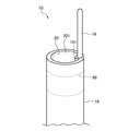
はじめに、図1、2を参照して、本実施形態の医療機器の概要について説明する。
本実施形態の医療機器は長尺状のカテーテル10である。
このカテーテル10は、カテーテル10の長手方向に沿って内部にメインルーメン20が形成されるとともに、遠位端の端面が開口し、メインルーメン20に連通する開口部201が形成された管状本体(シース)16と、前記管状本体16の長手方向に沿って延在し、前記管状本体16の遠位端から突出した突起部18とを有する。
突起部18は、管状本体16を体腔内に挿入する際に、管状本体16の体腔内への挿入をガイドする。この突起部18は、可撓性を有する。また、突起部18の径は、管状本体16の径よりも小さい。突起部18の遠位端部は、鈍頭形状である。
First, an outline of the medical device of the present embodiment will be described with reference to FIGS.
The medical device of the present embodiment is a
The
The
次に、本実施形態のカテーテル10について詳細に説明する。
カテーテル10は、シース16、ブレード層50、中空管32、コート層64、操作線40、マーカ66を備える。
カテーテル10は、液状あるいは粒子状の薬剤を患部に供給するメインルーメン20が長手方向(図1における左右方向)に設けられている。そして、メインルーメン20と隔離して設けられたサブルーメン30に操作線40が挿通されて、カテーテル10の遠位端部15を屈曲操作することができる。
Next, the
The
The
カテーテル10は、カテーテル10の本体をなすシース(管状本体)16を有する。シース16は、メインルーメン20が内部に形成された管状の内層21と、内層21と同種または異種の樹脂組成物からなり内層21の周囲に形成された外層60と、を積層してなる。
The
内層21には、一例として、フッ素系の熱可塑性ポリマー材料を用いることができる。より具体的には、ポリテトラフルオロエチレン(PTFE)やポリビニリデンフルオライド(PVDF)、ペルフルオロアルコキシフッ素樹脂(PFA)などを用いることができる。
内層21にフッ素系樹脂を用いることにより、カテーテル10のメインルーメン20を通じて造影剤や薬液などを患部に供給する際のデリバリー性が良好となる。
For example, a fluorine-based thermoplastic polymer material can be used for the
By using a fluorine-based resin for the
シース16の主たる肉厚を構成する外層60の主成分としては、熱可塑性ポリマーが広く用いられる。一例として、ポリイミド(PI)、ポリアミドイミド(PAI)、ポリエチレンテレフタレート(PET)のほか、ポリエチレン(PE)、ポリアミド(PA)、ナイロンエラストマー、ポリウレタン(PU)、エチレン−酢酸ビニル樹脂(EVA)、ポリ塩化ビニル(PVC)またはポリプロピレン(PP)、熱可塑性エラストマーであるポリエーテルブロックアミド共重合体からなる群から選択される1種以上の材料を用いることができる。
As the main component of the
メインルーメン20の先端側に連通する開口部201は、シース16の遠位端DEに形成されている。一方、メインルーメン20の基端側に連通する開口部は近位端部17(図7を参照)の端面または周面に形成されている。ここで、カテーテル10の遠位端部15とは、カテーテル10の遠位端DEを含む所定の長さ領域をいう。同様に、カテーテル10の近位端部17(図7を参照)とは、カテーテル10の近位端PEを含む所定の長さ領域をいう。
シース16の先端側の開口部の開口平面、シース16の基端側の開口部201の開口平面は、シース16の長手方向と直交している。すなわち、シース16の遠位端側の端面および近位端側の端面は、シース16の長手方向と直交している。また、本実施形態では、シース16の全長にわたって、シース16の長手方向と直交する断面の外形は円形である。
An
The opening plane of the opening on the distal end side of the
ここで、図1に示すように、シース16の遠位端側には、厚肉部161が形成されている。この厚肉部161は、シース16のメインルーメン20側の内周縁の一部から、前記メインルーメン20側に向かって凸状に突出するとともに、シース16の長手方向に延在する。
この厚肉部161は、外層60の一部および内層21の一部で構成されるが、主として外層60の一部により構成されている。
ここで、図1に示すように、厚肉部161のメインルーメン径方向の厚みT2は、シース16の遠位端側から、近位端側に向かって略等しくてもよいが、厚肉部161のメインルーメン径方向の厚みT2が、シース16の遠位端側から、近位端側に向かって順次薄くなるようにしてもよい。このようにすることで、シース16の遠位端側に向かって、シース16の剛性が急激に変化してしまうことを抑制できる。
Here, as shown in FIG. 1, a
The
Here, as shown in FIG. 1, the thickness T2 in the main lumen radial direction of the
この厚肉部161内には、芯材181の一部が挿入されている。
ここで、突起部18について詳細に説明する。
突起部18は、図1および図2に示すようにシース16の長手方向に沿って延在し、シース16の遠位端から突出している。
より具体的には、突起部18は、シース16の遠位端の端面から突出し、前述した厚肉部161に接続(埋設)されている。突起部18は、可撓性を有し、その径がシース16の径よりも小さい。そして、突起部18の遠位端部は、カテーテル10の遠位端側に向かって凸状に湾曲しており、鈍頭形状である。
なお、突起部18の可撓性は、突起部18を構成する芯材181、樹脂層184、コイル182の材料を適宜選択することで得られ、突起部18は、耐キンク性に優れている。
A part of the
Here, the
As shown in FIGS. 1 and 2, the
More specifically, the protruding
The flexibility of the
突起部18は、芯材181と、この芯材181の周囲を取り囲むように配置されたコイル182と、固定部183とを備える。
突起部18は、その曲げ剛性が、シース16の曲げ剛性よりも高い。
芯材181は、その径が5〜20μmであり、金属、たとえば、Ni−Ti合金、Cu−Zn−X合金(X=Be,Si,Sn,Al,Ga)、Ni−Al合金等の超弾性合金で構成される。芯材181の曲げ剛性は、シース16の遠位端部の曲げ剛性よりも高い。
芯材181は、シース16の遠位端の端面から突出した第一部分181Aと、シース16の厚肉部161に埋め込まれた第二部分181Bとを備える。
第一部分181Aは、シース16の遠位端の厚肉部161から、カテーテル10の遠位端側に突出し、シース16の長手方向に沿って延在している。第一部分181Aは、その径が、近位端側から遠位端側まで等しく、第一部分181Aは、たとえば、円柱形状である。
The protruding
The protruding
The
The
The
第二部分181Bは、シース16の長手方向に沿って延在し、シース16の厚肉部161に埋め込まれている。
第二部分181Bのシース16の延在方向の長さ寸法は、1〜2cm程度である。
第二部分181Bは、メインルーメン20の径方向の厚みTが、遠位端側から近位端に向かって連続的に減少し、薄肉化されている。ただし、図3の平面図に示すように、第二部分181Bの厚さ方向および、芯材181の延在方向と直交する方向の幅Wは、遠位端側から近位端にわたって均等である。
The
The length dimension in the extending direction of the
In the
なお、図4に示すように、第二部分181Bの幅Wが、遠位端側から近位端に向かって、連続して広くなるようにしてもよい。このようにすることで、第二部分181Bが厚肉部161から抜けにくくなる。
図3,4は、カテーテル10をその長手方向から直交する方向から見た図であり、第二部分181B側から見た図である。
As shown in FIG. 4, the width W of the
3 and 4 are views of the
また、本実施形態では、第二部分181B全体にわたって厚みTが遠位端側から近位端に向かって連続的に減少しているが、これに限らず、たとえば、第二部分181Bの一部、たとえば、近位端部近傍の領域のみの厚みが連続的に減少するようにしてもよい。
さらに、第二部分181Bは、厚肉部161に埋め込まれているため、シース16の補強層50よりも内側の領域に埋め込まれていることとなる。そして、カテーテル10を、その長手方向と直交する方向から、側面視した状態(第二部分181B側から見た状態)において、第二部分181Bの近位端部は、補強層50と重なりあっている。なお、補強層50については、詳しくは後述する。
In the present embodiment, the thickness T continuously decreases from the distal end side toward the proximal end over the entire
Furthermore, since the
コイル182は、芯材181の第一部分181Aの周囲を囲む。コイル182の材料としては、金、白金、銀、ビスマス、タングステンまたこれらのうち2種類以上の合金(例えば、白金−タングステン)、もしくは他の金属との合金(例えば、金−イリジウム、白金−イリジウム)などが挙げられる。コイル182の曲げ剛性は、シース16の遠位端部の曲げ剛性よりも高い。
コイル182は、第一部分181Aに当接して設けられている。コイル182を構成する巻き線を第一部分181Aにまきつけてもよく、あらかじめコイル182を作成し、コイル182内部に、第一部分181Aを挿入してもよい。
コイル182の近位端側の端部は、接着剤や半田付け等で芯材181に固定することが好ましい。一方で、コイル182の遠位端側の端部は、固定部183により、芯材181に固定されている。
The
The
The end portion on the proximal end side of the
固定部183は、カテーテル10の遠位端側に向かって凸状に湾曲したものであり、芯材181と同様の金属で構成することができる。固定部183を溶融させて第一部分181Aの遠位端部に固定するとともに、コイル182の端部を固定部183に固定する。この固定部183は、突起部18の遠位端部を構成し、突起部18の遠位端は、閉塞したものとなる。
固定部183の湾曲面は円弧状に湾曲している。このようにすることで、体腔内にカテーテルを進入させる際、体腔内壁に突起部18を面接触させ、体腔への刺激を低減させることができる。
The fixing
The curved surface of the fixed
なお、少なくとも、第一部分181A、コイル182、固定部183は、樹脂層184により一体的に被覆されている。なお、第二部分181Bも樹脂層184で被覆されていてもよいが、樹脂層184で被覆されていなくてもよい。たとえば、突起部18を強固にシース16に固定するために、第二部分181Bの表面を粗面化し、微細な凹凸を形成して、シース16の樹脂材料が第二部分181Bにアンカーするようにしてもよい。このような場合には、第二部分181Bは、樹脂層184で被覆されないことが好ましい。
樹脂層184としては、ポリウレタン、ポリエチレン、ポリ塩化ビニル、ポリエステル、ポリプロピレン、ポリアミド、ポリスチレン、フッ素系樹脂、シリコーンもしくは各々のエラストマー(例えば、ポリエステルエラストマー)およびそれらの複合材料が好適に使用できる。
At least the
As the
ここで、突起部18のシース16からの突出寸法は、たとえば、1cm以下である。1cm以下とすることで、メインルーメン20から薬剤を体腔内に供給する際に、突起部18がじゃまにならない。
また、突起部18のシース16から突出した領域の外径は、シース16の遠位端の外径よりも小さく、たとえば、10μm〜50μmである。
シース16の遠位端の外径Aと、突起部18のシース16から突出した領域の外径Bとの比である、A:Bは、20:1〜100:1であることが好ましい。
このように突起部18の径を非常に小さくすることで、体腔内壁への刺激を小さくでき、かつ、血管選択性を良好にすることができる。
Here, the protrusion dimension of the
Moreover, the outer diameter of the area | region which protruded from the
It is preferable that A: B, which is a ratio of the outer diameter A of the distal end of the
Thus, by making the diameter of the
次に、サブルーメン30について説明する。
外層60の内部には、一つまたは複数のサブルーメン30が遠位端部15から近位端部17に亘って形成されている。
図5に示すように、本実施形態のカテーテル10は、複数個のサブルーメン30がメインルーメン20の周方向に分散して配置されている。また、メインルーメン20とサブルーメン30とは互いに離間して個別に設けられている。具体的には、本実施形態のカテーテル10の場合、4個のサブルーメン30がメインルーメン20の周囲に90度間隔で配置されている。なお、図5においては、サブルーメン30が3つしか図示されていないが、4つめのサブルーメン30は、突起部18の第二部分181Bの延長線上にあり、第二部分181Bよりも、近位端側に設けられている。そのため、図5の断面図では図示されない。また、図1の断面図においても、突起部18の第二部分181Bの延長線上にあるサブルーメン30は、第二部分181Bよりも、カテーテル10の近位端側に配置され、第二部分181Bから離れた位置に配置されているため、図示されていない。
なお、サブルーメン30の個数は、これに限られるものではない。
Next, the sub-lumen 30 will be described.
Inside the
As shown in FIG. 5, in the
The number of sub-lumens 30 is not limited to this.
操作線40は、本実施形態では、1本のみ設けられており、図5に示すように、操作線40と、突起部18(図5では、第二部分181Bが図示されている)とは、メインルーメン20の中心位置を挟んで対向配置されている。すなわち、シース16の遠位端側の端面に形成された開口部201側からの平面視において、操作線40と、突起部18とは、メインルーメン20の中心位置を挟んで対向配置されている。
このように操作線40を配置することで、操作線40を引っ張り、カテーテルの先端を操作線40側に屈曲させやすく(図7参照)、突起部18を分岐血管等にひっかける操作がしやすくなる。
In the present embodiment, only one
By arranging the
操作線40は、カテーテル10の遠位端部15に固定(係止)されている。具体的には、本実施形態では、操作線40は、カテーテル10の遠位端部15を構成するマーカ66に固定されている。
The
操作線40は円形断面の線材あるいは、複数の細線で構成された撚り線であり、外径は30〜60μm程度である。
操作線40の材料としては、たとえば、PEEK、PPS、ポリブチレンテレフタレート(PBT)、PIもしくはPTFEなどの高分子ファイバー、または、ステンレス鋼(SUS)、耐腐食性被覆した鋼鉄線、チタンもしくはチタン合金などの可撓性の金属線を用いることができる。
なお、本実施形態では、操作線40は、1本であるとしたが、これに限られるものではなく、複数本、設けられていてもよい。対向する2個のサブルーメン30にそれぞれ摺動可能に1本ずつ操作線40が挿通されていてもよい。
The
Examples of the material of the
In the present embodiment, the number of
すなわち、図6に示すように、2本の操作線40が、突起部18(図6では第二部分181Bが図示されている)と前記メインルーメン20の開口部の中心点とを結ぶ直線を挟んで、対称位置に配置されていてもよい。すなわち、シース16の遠位端側の開口部側からの平面視において、2本の操作線40が、突起部18と前記メインルーメン20の開口部の中心点とを結ぶ直線を挟んで、対称位置に配置されていてもよい。
このように操作線40を配置することで、一方の操作線40側にシース16を屈曲させる場合、他方の操作線40側にシース16を屈曲させる場合の操作性に差が生じにくくなり、操作性に優れたカテーテル10とすることができる。
That is, as shown in FIG. 6, the two
By arranging the
中空管32は、前述したサブルーメン30を画定するものであり、内部にサブルーメン30が貫通して形成された管状の部材である。中空管32は、図1に示すように、シース16の長手方向に沿って延在する。
中空管32は、外層60を構成する樹脂組成物よりも、耐熱性、柔軟性および摺動性の高い熱可塑性の樹脂組成物で構成される。一例としては、PTFE、PFAもしくは四フッ化エチレン・六フッ化プロピレン共重合体(FEP)などのフッ素系ポリマー材料のほか、PI、PAI、ポリサルフォン(PSF)、ポリエーテルサルフォン(PES)、ポリフェニレンサルファイド(PPS)、ポリエーテルエーテルケトン(PEEK)、ポリエーテルイミド(PEI)もしくは液晶ポリマー(LCP)などの非フッ素系ポリマー材料が用いられる。
The
The
中空管32を成形するポリマー材料には、シリカ、タルク、炭酸カルシウム、水酸化アルミニウム、水酸化マグネシウム、二酸化チタンなどの無機フィラーを混合してもよい。無機フィラーをポリマー材料に混合して中空管32の内壁面の平滑性を向上することにより、中空管32に対して操作線40を挿通する際の作業性の向上と、操作線40の牽引操作時の摩擦低減が図られる。
なお、中空管32の引っ張り弾性率は、外層60の引っ張り弾性率よりも高い。
The polymer material for forming the
Note that the tensile elastic modulus of the
外層60の周囲には、カテーテル10の最外層として形成された親水性のコート層64が積層形成されている。コート層64は、シース16のうち遠位端DE側の一部の長さ領域に設けられている。
コート層64は、ポリビニルアルコール(PVA)やポリビニルピロリドンなどの親水性の樹脂材料で成形するか、または外表面に潤滑処理を施すことにより、少なくとも外表面が親水性である。
A
The
本実施形態のカテーテル10は、シース16を補強するための補強層50を有している。この補強層50は、内層21の周囲にワイヤ52を編成してなるブレード層50である。ブレード層50は、外層60に内包されている。
本実施形態のカテーテル10においては、図1、5に示すように、操作線40がそれぞれ挿通されたサブルーメン30は、外層60の内部であって、ブレード層50の外側に形成されている。
なお、補強層は、ブレード層50に限らず、コイル層であってもよい。
このような補強層50を設けることで、シース16が補強されて、カテーテル10から薬剤を吐出させやすくすることができる。
The
In the
The reinforcing layer is not limited to the blade layer 50 and may be a coil layer.
By providing such a reinforcing layer 50, the
また、図1に示すように、カテーテル10の遠位端部15には、X線等の放射線が不透過な材料からなるリング状のマーカ66が設けられている。具体的には、マーカ66には白金などの金属材料を用いることができる。本実施形態のマーカ66は、メインルーメン20の周囲であって、外層60の内部に設けられている。
As shown in FIG. 1, the
操作線40の先端(遠位端)は、カテーテル10の遠位端部15に固定されている。操作線40の先端を遠位端部15に固定する態様は特に限定されない。たとえば、操作線40の先端をマーカ66に締結してもよく、シース16の遠位端部15に溶着してもよく、または接着剤によりマーカ66またはシース16の遠位端部15に接着固定してもよい。
The distal end (distal end) of the
ここで、本実施形態のカテーテル10の代表的な寸法について説明する。メインルーメン20の半径は200〜300μm程度、内層21の厚さは10〜30μm程度、外層60の厚さは50〜150μm程度、補強層50の外径(直径)は、500μm〜860μm程度、補強層50の内径(直径)は420μm〜660μm程度とすることができる。そして、カテーテル10の軸心からサブルーメン30の中心までの半径は300〜350μm程度、サブルーメン30の内径は40〜100μm程度とし、操作線40の太さを30〜60μm程度とすることができる。また、中空管32の肉厚は、3〜15μm程度とすることができる。そして、カテーテル10の最外径(半径)を350〜490μm程度とすることができる。
すなわち、本実施形態のカテーテル10の外径は直径1mm未満であり、腹腔動脈などの血管に挿通可能である。本実施形態のカテーテル10は血管挿通用である。
Here, typical dimensions of the
That is, the outer diameter of the
次に、図7を用いて、本実施形態のカテーテル10の動作を説明する。
Next, operation | movement of the
図7(A)に示すように、操作線40の近位端41は、サブルーメン30から近位側に突出している。また、操作線40の近位側には、操作線40を牽引してカテーテル10の遠位端部15を屈曲させる操作部70が設けられている。操作部70の構造に関する詳細な図示および説明は省略する。
As shown in FIG. 7A, the
本実施形態のカテーテル10において、図7(B)に示すように、操作線40の近位端41を基端側(同図における右方)に牽引すると、カテーテル10の遠位端部15には引張力が与えられる。かかる引張力が所定以上であると、カテーテル10の軸心から当該操作線40が挿通されているサブルーメン30の側に向かって、遠位端部15が屈曲する。このため、本実施形態のカテーテル10は、たとえば分岐する血管等の体腔に対して、所望の方向に進入させることが可能である。
さらに、突起部18は、可撓性を有するとともに、シース16よりも曲げ剛性が高いため、主血管(主体腔)から分岐する分岐血管(分岐する体腔)内に挿入させる際に、突起部18が主血管と分岐血管とのコーナー部分につきあたることで、突起部18が所望の角度で屈曲して、突起部18を、主血管から分岐血管内に挿入させることができる。シース16は突起部18に追従し、突起部18にガイドされて、分岐血管内を進行することとなる。これによっても、本実施形態のカテーテル10は、たとえば分岐する血管等の体腔に対して、所望の方向に進入させることが可能である。
In the
Furthermore, since the
なお、操作線40は、きわめて微細径の線材からなるため、その近位端41をシース16に対して押し込んだ場合には、当該操作線40は座屈し、カテーテル10の遠位端部15には押込力が実質的に与えられることはない。
このため、操作者が操作線40をカテーテル10に対して押し込んだとしても、操作線40がカテーテル10の遠位端部15から外れて遠位端DEより突出することがない。このため、体腔内に挿入されたカテーテル10を操作するに際して、被験者の安全が図られている。
Since the
For this reason, even if the operator pushes the
なお、本発明においては、図8に示すように、突起部18をあらかじめリシェイプさせおいてもよい。
このようにすることで、分岐する血管等にカテーテル10を進入しやすくすることができる。
突起部18を屈曲させてリシェイプする際、コイル182の巻き線間がのびてコイル182が塑性変形する。そして、コイル182の形状を保持する力が、芯材181の復元力に勝り、突起部18が屈曲した状態となる。ただし、芯材181は超弾性であるので、塑性変形はしておらず、コイル182の形状を変えることで、突起部18を直線状に戻すことも、他の形状とすることも可能となる。
In the present invention, as shown in FIG. 8, the
In this way, the
When the
<カテーテルの製造方法>
次に、図9を参照して、カテーテル10の製造方法について説明する。
はじめに、あらかじめ突起部18を作製しておく。芯材181の第一部分181Aの周囲にコイル182を巻き、コイル182と、芯材181とを固定部183で固定しておく。その後、コイル182、固定部183、芯材181を樹脂層184で被覆する。
<Catheter production method>
Next, a method for manufacturing the
First, the
次に、シース16を作製する。
図9に示すように、マンドレルM(芯材)を用意する。このマンドレルMには、厚肉部に対応する溝部M1が、先端に形成されている。内層21の材料を、マンドレルMの周囲に押し出す。溝部M1には、内層21の材料が入り込むこととなる。
次に、内層21の周囲に、ブレード層50を被せる。一方で、マンドレルMの溝部M1内の内層21上に、突起部18の芯材181の第二部分181Bを重ねて配置する。
一方で、あらかじめ外層60を押し出し成形しておく。ただし、ここでは、外層60のうち、マーカ66よりも、近位端側の領域のみ(図1の点線よりも、図面右側の領域の外層601)を押し出し成形する。すなわち、ここで作成する外層601は、外層60よりも長さが短いものとなる。
具体的には、外層601を構成する樹脂を含む材料を図示しないマンドレル(芯材)の周囲に押し出す。このとき、外層601において、後に中空管32が埋設されることによりサブルーメン30が形成される位置の各々に、長手方向に沿う長尺な中空部(孔)が形成されるように、ガス等の流体を吐出しながら押出成形する。
押出成形後、マンドレルを引き抜くことにより、中空形状の外層601を作成することができる。
Next, the
As shown in FIG. 9, a mandrel M (core material) is prepared. In the mandrel M, a groove portion M1 corresponding to the thick portion is formed at the tip. The material of the
Next, the blade layer 50 is placed around the
On the other hand, the
Specifically, a material containing a resin constituting the
After extrusion, the hollow
さらに、中空管32も中空管32を構成する樹脂を含む材料を押出成形することによって作成する。長手方向に沿う長尺な中空部が形成されるように、中空管32の材料に対してガス等の流体を吐出しながら押出成形する。
Further, the
その後、内層21の周囲にブレード層50を被せた状態で、このブレード層50の周囲に外層601を被せる。
次に、外層601の中空部分に対し、中空管32を挿入する。
その後、外層601の周囲に、図示しない樹脂製の熱収縮チューブを被せる。次に、加熱により、熱収縮チューブを収縮させて、外層601、ブレード層50、内層21、中空管32を内層21の径方向に向かって外側から加圧する。また、前記加熱により、外層601を溶融させる。なお、加熱温度は、外層601の溶融温度よりも高く、内層21、中空管32の溶融温度よりも低い。この加熱により、外層601と内層21とが溶着により接合する。このとき、外層12を構成する材料が、ブレード層50を内包する。また、外層601と中空管32とが溶着により接合する。
Thereafter, the
Next, the
Thereafter, a resin heat shrinkable tube (not shown) is placed around the
次に、熱収縮チューブに切り込みを入れ、該熱収縮チューブを引き裂くことによって、熱収縮チューブを外層から取り除く。その後、中空管32内に操作線40を挿入する。
Next, the heat shrinkable tube is removed from the outer layer by making a cut in the heat shrinkable tube and tearing the heat shrinkable tube. Thereafter, the
また、別途、環状の金属部材であるマーカ66を準備する。
次に、操作線40の先端を中空管32から遠位端側に突出させておき、マーカ66に対して、操作線40の先端を固定する。そして、操作線40を近位端側に引っ張って、操作線40を中空管32内に戻し、マーカ66を外層601に当接させる。その後、マーカ66よりも、遠位端側の領域を構成する外層602(図1参照)の樹脂材料を溶融させて、この溶融した樹脂材料を、マーカ66を埋め込むとともに、突起部18の第二部分181Bを埋め込むように、外層601の先端に供給する。
これにより、厚肉部161が形成され、突起部18の第二部分181Bが厚肉部161に埋め込まれることとなる。
なお、マーカ66の半径は、開口部201側からの平面視における突起部18の第一部分181Aとメインルーメン20の中心点までの距離よりも大きい。
その後、再度、熱収縮チューブを外層60の周囲に被せて、外層60の成形をおこなってもよい。
なお、本実施形態では、マンドレルMの溝部M1に芯材181の第二部分181Bを配置しておくとしたが、これに限らず、ダミーの芯材を用意して、マンドレルMの溝部M1にダミー芯材を配置してもよい。マーカ66に、操作線40を固定した後、ダミーの芯材を、突起部18の芯材181と置換する。その後、マーカ66よりも、遠位端側の領域を構成する外層602の樹脂材料を溶融させて、マーカ66よりも遠位端側の領域の外層602を形成する。
Separately, a
Next, the tip of the
Thereby, the
The radius of the
Thereafter, the
In the present embodiment, the
次に、別途作成した操作部に対し、操作線40の基端部を連結する。
次に、コート層64を形成する。
以上より、カテーテル10を得ることができる。
Next, the base end portion of the
Next, the
From the above, the
次に、本実施形態の作用効果について説明する。
本実施形態においては、シース16の遠位端に突起部18が設けられている。そのため、カテーテル10を血管等の体腔内に挿入する際には、シース16よりも先に、シース16の遠位端に設けられた突起部18が体腔内に進入する。この突起部18は、シース16を体腔内に挿入する際に、シース16の体腔への進行をガイドするものであり、その径がシース16よりも小さく、可撓性を有する。そのため、突起部18が体腔内壁に接触したとしても、体腔内壁への刺激は比較的少ないものとなる。これにより、体腔の収縮が抑制でき、カテーテル10の操作性を確保することができる。特に、体腔の収縮を防止できるので、カテーテル10を体腔へ進入させやすいものとすることができる。
さらには、体腔の収縮を防止できるので、メインルーメン20を介して、液状あるいは粒子状の薬剤を適量、患部に供給することができる。収縮していない通常の血管の径に対応した粒径を選択して使用する粒子状の薬剤があるが、このような粒子状の薬剤を、メインルーメン20を介して、患部に確実に供給することが可能となる。
Next, the effect of this embodiment is demonstrated.
In the present embodiment, a
Furthermore, since contraction of the body cavity can be prevented, an appropriate amount of liquid or particulate medicine can be supplied to the affected area via the
さらに、突起部18のうち、シース16から突出した部分の外径は、シース16の遠位端の外径よりも小さいため、血管に挿入しやすい。たとえば、分岐した血管枝にカテーテル10を挿入する際に、所望の血管枝にカテーテルを挿入させることができ、血管選択性に優れたカテーテル10となる。
Furthermore, since the outer diameter of the
さらに、本実施形態では、突起部18の遠位端は、固定部183により、閉塞されている。これにより、突起部18内に血液等の体液が入ってしまうことを防止できる。
また、開口部201は、シース16の遠位端面に形成されている。これにより、メインルーメン20から所望の位置に薬剤を供給することができる。
さらには、シース16の遠位端側の開口部201の開口面が、シース16の長手方向に対して傾斜している場合、シース16の周方向の回転角度によっては、所望の位置に薬剤を供給することが難しくなる。これに対し、本実施形態では、シース16の遠位端側の開口部201の開口面は、シース16の長手方向に対して直交している。これにより、メインルーメン20から所望の位置に薬剤を供給することができる。
Further, in the present embodiment, the distal end of the
The
Furthermore, when the opening surface of the
さらに、本実施形態では、長手方向と直交する方向からカテーテル10を平面視した際に、芯材181の第二部分181Bと、補強層50とが重なりあっている。このようにすることで、補強層50と芯材181との間の隙間で、カテーテルが折れ曲がり、キンクが発生してしまうことが防止される。
また、本実施形態では、第二部分181Bは、シース16の径方向の厚みが、遠位端側から近位端に向かって連続的に減少し、薄肉化されている。これにより、補強層50と芯材181との境界部分での曲げ剛性の急激な変化が抑制できる。
Furthermore, in the present embodiment, when the
Further, in the present embodiment, the thickness of the
また、芯材181の第二部分181Bは、補強層50よりも内側の外層60に埋め込まれている。これにより、芯材181が補強層50よりも外側に抜けにくくなる。
さらに、本実施形態では、シース16の遠位端部に、シース16のメインルーメン20側の周縁の一部から、メインルーメン20側に向かって突出する厚肉部161を形成している。そして、この厚肉部161に、芯材181を固定し、厚肉部161から突起部18が突出する構造となっている。このような構造とすることで、シース16の遠位端部において、長手方向と直交する方向の断面の外形を円形とすることができ、シース16自体も体腔内に進入させやすい構造とすることができる。
Further, the
Furthermore, in the present embodiment, a
本実施形態では、補強層として、ブレード層50を設けている。これにより、カテーテル10の剛性を確保することができる。一方で、カテーテル10の遠位端の屈曲性は、突起部18で確保することができる。
このように、本実施形態のカテーテル10は、剛性と屈曲性とのバランスに優れたものとなる。
In this embodiment, the blade layer 50 is provided as a reinforcing layer. Thereby, the rigidity of the
Thus, the
なお、特開2008−86476号公報には、吸引ルーメンよりも先端に突出したガイドワイヤルーメンが設けられた吸引カテーテルが開示されている。さらに、特開2008−132256号公報には、脱血ルーメンよりも先端に返血ルーメンが設けられた、バスキュラーアクセスカテーテルが開示されている。
ガイドワイヤルーメンや、返血ルーメンは、いずれのカテーテルにおいても、樹脂管で構成されており、比較的柔らかいものとなっている。そのため、本発明の突起部のように、シースを体腔内に挿入する際に、シースをガイドする機能は有していない。
たとえば、ガイドワイヤを使用せずに、主血管から分岐血管内に、カテーテルを進行させる際、上述した公報に開示されたカテーテルでは、ガイドワイヤルーメンや、返血ルーメンを構成する樹脂管がやわらかいため、主血管と分岐血管とのコーナー部分に樹脂管が引っかかったとしても、樹脂管が2つに折れ曲がってしまう(樹脂管の先端が、カテーテルの近位端側に向かうように樹脂管が鋭角で屈曲してしまう)。この状態で、さらに、カテーテルを主血管に対して押し込むと、カテーテルは主血管内を進行してしまい、分岐血管内に入ることができない。
Japanese Patent Application Laid-Open No. 2008-86476 discloses a suction catheter provided with a guide wire lumen protruding at the tip of the suction lumen. Furthermore, Japanese Patent Application Laid-Open No. 2008-132256 discloses a vascular access catheter in which a blood return lumen is provided at the tip rather than a blood removal lumen.
The guide wire lumen and the blood return lumen are made of a resin tube in each catheter and are relatively soft. Therefore, unlike the protrusion of the present invention, it does not have a function of guiding the sheath when it is inserted into the body cavity.
For example, when a catheter is advanced from a main blood vessel into a branch blood vessel without using a guide wire, the guide tube lumen and the resin tube constituting the blood return lumen are soft in the catheter disclosed in the above publication. Even if the resin tube is caught at the corner between the main blood vessel and the branch blood vessel, the resin tube bends in two (the resin tube has an acute angle so that the tip of the resin tube faces the proximal end side of the catheter). Bend). In this state, when the catheter is further pushed into the main blood vessel, the catheter advances in the main blood vessel and cannot enter the branch blood vessel.
なお、本発明は前述の実施形態に限定されるものではなく、本発明の目的を達成できる範囲での変形、改良等は本発明に含まれるものである。
たとえば、前記実施形態では、カテーテル10を長手方向と直交する方向からの平面視において、ブレード層50と、芯材181の第二部分181Bとが重なりあうようにして配置されていたが、これに限られるものではない。たとえば、カテーテル10を長手方向と直交する方向からの平面視において、ブレード層50と、芯材181の第二部分181Bとが重ならないものの、ブレード層50と芯材181の第二部分181Bとの間に隙間が形成されないように、芯材181を配置してもよい。
このようにすることで、カテーテル10の長手方向に沿った剛性の局所的な変化を抑制することができる。
It should be noted that the present invention is not limited to the above-described embodiments, and modifications, improvements, and the like within the scope that can achieve the object of the present invention are included in the present invention.
For example, in the above-described embodiment, the
By doing in this way, the local change of the rigidity along the longitudinal direction of the
さらには、シース16のメインルーメン20側の周縁の一部から、メインルーメン20側に向かって突出する厚肉部161を形成したが、厚肉部を、メインルーメン20と反対側に突出するものとしてもよい。このようにすることで、メインルーメン20が長手方向と直交する断面が厚肉部161の存在により小さくなることがなく、薬剤を吐出させやすくすることができる。
Furthermore, although the
さらには、前記実施形態では、開口部201側からの平面視において、操作線40は、前記開口部の中心点を挟んで突起部18と対向する第一の位置に設けられていたが、これに限らず、開口部201の中心点を挟んで前記第一の位置と対向する第二の位置に配置されていてもよい。たとえば、突起部18の長手方向の延長線上に、操作線40が配置されていてもよい。このように操作線40を配置することで、カテーテルの遠位端部を鋭角に屈曲させやすくなる。
さらに、前記実施形態では、カテーテルは、操作線40を有するとしたが、操作線はなくてもよい。操作線を有しない場合であっても、突起部18が設けられていることで、突起部18によりシースがガイドされるため、所望の位置にシースを挿入することができる。
また、前記実施形態では医療機器の一例として、カテーテルを示したが、これに限られるものではない。
Furthermore, in the embodiment, the
Furthermore, in the said embodiment, although the catheter had the
Moreover, although the catheter was shown as an example of a medical device in the said embodiment, it is not restricted to this.
10 カテーテル
15 遠位端部
16 シース(管状本体)
17 近位端部
18 突起部
20 メインルーメン
21 内層
30 サブルーメン
32 中空管
40 操作線
41 近位端
50 ブレード層(補強層)
52 ワイヤ
60 外層
64 コート層
66 マーカ
70 操作部
161 厚肉部
181 芯材
181A 第一部分
181B 第二部分
182 コイル
183 固定部
184 樹脂層
201 開口部
601 外層
602 外層
DE 遠位端
M マンドレル
M1 溝部
PE 近位端
10
17
52
Claims (17)
当該医療機器の長手方向に沿って内部にメインルーメンが形成されるとともに、遠位端の端面が開口し、前記メインルーメンに連通する開口部が形成された管状本体と、
前記管状本体を体腔内に挿入する際に、前記管状本体の体腔内への挿入をガイドする突起部とを有し、
前記突起部は、前記管状本体の長手方向に沿って延在し、前記管状本体の遠位端から突出し、
前記突起部は、可撓性を有し、前記突起部の径は、前記管状本体の径よりも小さい医療機器。 A long medical device,
A tubular body in which a main lumen is formed inside along the longitudinal direction of the medical device, an end surface of a distal end is opened, and an opening communicating with the main lumen is formed;
A projection that guides insertion of the tubular body into the body cavity when the tubular body is inserted into the body cavity;
The protrusion extends along a longitudinal direction of the tubular body and protrudes from a distal end of the tubular body;
The protrusion has flexibility, and the diameter of the protrusion is smaller than the diameter of the tubular body.
前記突起部の遠位端は、閉塞されている医療機器。 The medical device according to claim 1, wherein
The distal end of the protrusion is a medical device that is closed.
前記突起部の遠位端部は、鈍頭形状である医療機器。 The medical device according to claim 1 or 2,
The distal end of the protrusion is a medical device having a blunt shape.
前記管状本体の前記開口部の開口平面は、前記管状本体の長手方向と直交する医療機器。 The medical device according to any one of claims 1 to 3,
A medical device in which an opening plane of the opening of the tubular body is orthogonal to a longitudinal direction of the tubular body.
前記突起部は、金属製の芯材を有する医療機器。 The medical device according to any one of claims 1 to 4,
The protrusion is a medical device having a metal core.
前記突起部は、前記芯材の周囲を取り囲むように配置されたコイルと、
前記芯材と前記コイルとを固定し、前記突起部の遠位端部を構成する固定部とを備える医療機器。 The medical device according to claim 5,
The protrusion is a coil disposed so as to surround the core material;
A medical device comprising: a fixing portion that fixes the core material and the coil and constitutes a distal end portion of the protruding portion.
前記芯材は、超弾性合金製である医療機器。 The medical device according to claim 6,
The core material is a medical device made of a superelastic alloy.
前記メインルーメンを取り囲むように配置された金属製の補強層を有し、
長手方向と直交する方向から当該医療機器を平面視した際に、前記芯材の近位端と、前記補強層とが重なりあっている医療機器。 The medical device according to any one of claims 5 to 7,
A metal reinforcing layer arranged to surround the main lumen;
A medical device in which a proximal end of the core material and the reinforcing layer overlap each other when the medical device is viewed in a plan view from a direction orthogonal to the longitudinal direction.
前記補強層は、樹脂製の前記管状本体に埋め込まれており、
前記芯材の近位端は、前記管状本体の前記補強層よりも内側の領域に埋め込まれている医療機器。 The medical device according to claim 8,
The reinforcing layer is embedded in the tubular body made of resin,
A medical device in which a proximal end of the core member is embedded in a region inside the reinforcing layer of the tubular body.
前記芯材は、前記管状本体の遠位端から突出する第一部分と、前記第一部分に接続されるとともに、前記管状本体の近位端に向けて前記管状本体に埋め込まれた第二部分とを備え、
前記第二部分は、前記芯材の遠位端側から前記芯材の近位端に向かって連続的に厚みが減少し、薄肉化されている医療機器。 The medical device according to claim 8 or 9,
The core includes a first portion protruding from a distal end of the tubular body, and a second portion connected to the first portion and embedded in the tubular body toward the proximal end of the tubular body. Prepared,
The second part is a medical device in which the thickness is continuously reduced from the distal end side of the core member toward the proximal end of the core member to reduce the thickness.
前記管状本体の遠位端部には、前記管状本体の前記メインルーメン側の内周面の一部から、前記メインルーメン側に向かって突出するとともに、前記管状本体の長手方向に延在する厚肉部が形成されており、前記芯材の前記第二部分は、前記厚肉部に埋め込まれている医療機器。 The medical device according to claim 10,
The distal end of the tubular body has a thickness protruding from the part of the inner peripheral surface of the tubular body on the main lumen side toward the main lumen side and extending in the longitudinal direction of the tubular body. A medical device in which a meat part is formed, and the second part of the core is embedded in the thick part.
遠位端が前記管状本体に係合した操作線を有し、
前記操作線の近位端を牽引することで、前記管状本体の遠位端が屈曲する医療機器。 The medical device according to any one of claims 1 to 11,
A distal end having an operating line engaged with the tubular body;
A medical device in which a distal end of the tubular body is bent by pulling a proximal end of the operation line.
前記開口部側からの平面視において、前記操作線は、前記開口部の中心点を挟んで前記突起部と対向する第一の位置または、前記開口部の中心点を挟んで前記第一の位置と対向する第二の位置に配置されている医療機器。 The medical device according to claim 12,
In a plan view from the opening side, the operation line is located at a first position facing the protruding portion across the central point of the opening, or the first position across the central point of the opening. And a medical device arranged in a second position opposite.
前記操作線を2本有し、
前記2本の操作線は、前記開口部側からの平面視において、前記突起部と前記開口部の中心点とを結ぶ直線を挟んで、対称位置に配置されている医療機器。 The medical device according to claim 12,
Having two operation lines,
The two operation lines are medical devices arranged in symmetrical positions across a straight line connecting the protrusion and the center point of the opening in a plan view from the opening.
前記突起部が屈曲した医療機器。 The medical device according to any one of claims 1 to 14,
A medical device in which the protrusion is bent.
当該医療機器はカテーテルである医療機器。 The medical device according to any one of claims 1 to 15,
The medical device is a medical device that is a catheter.
当該医療機器は、前記メインルーメンを介して、前記開口部から、液体状あるいは、粒子状の薬剤を吐出させるためのものである医療機器。 The medical device according to claim 16,
The medical device is a device for discharging liquid or particulate medicine from the opening through the main lumen.
Priority Applications (1)
| Application Number | Priority Date | Filing Date | Title |
|---|---|---|---|
| JP2012047566A JP2013180156A (en) | 2012-03-05 | 2012-03-05 | Medical equipment |
Applications Claiming Priority (1)
| Application Number | Priority Date | Filing Date | Title |
|---|---|---|---|
| JP2012047566A JP2013180156A (en) | 2012-03-05 | 2012-03-05 | Medical equipment |
Publications (1)
| Publication Number | Publication Date |
|---|---|
| JP2013180156A true JP2013180156A (en) | 2013-09-12 |
Family
ID=49271225
Family Applications (1)
| Application Number | Title | Priority Date | Filing Date |
|---|---|---|---|
| JP2012047566A Pending JP2013180156A (en) | 2012-03-05 | 2012-03-05 | Medical equipment |
Country Status (1)
| Country | Link |
|---|---|
| JP (1) | JP2013180156A (en) |
Cited By (10)
| Publication number | Priority date | Publication date | Assignee | Title |
|---|---|---|---|---|
| JP2017192815A (en) * | 2007-02-05 | 2017-10-26 | ボストン サイエンティフィック リミテッド | Thrombus removal device |
| JP2019083915A (en) * | 2017-11-02 | 2019-06-06 | コデン株式会社 | Indwelling apparatus and indwelling system |
| US11490909B2 (en) | 2014-05-19 | 2022-11-08 | Walk Vascular, Llc | Systems and methods for removal of blood and thrombotic material |
| US11497521B2 (en) | 2008-10-13 | 2022-11-15 | Walk Vascular, Llc | Assisted aspiration catheter system |
| US11510689B2 (en) | 2016-04-06 | 2022-11-29 | Walk Vascular, Llc | Systems and methods for thrombolysis and delivery of an agent |
| US11672561B2 (en) | 2015-09-03 | 2023-06-13 | Walk Vascular, Llc | Systems and methods for manipulating medical devices |
| US11678905B2 (en) | 2018-07-19 | 2023-06-20 | Walk Vascular, Llc | Systems and methods for removal of blood and thrombotic material |
| US12171444B2 (en) | 2021-02-15 | 2024-12-24 | Walk Vascular, Llc | Systems and methods for removal of blood and thrombotic material |
| JP7627126B2 (en) | 2021-02-22 | 2025-02-05 | テルモ株式会社 | Catheter System |
| US12274458B2 (en) | 2021-02-15 | 2025-04-15 | Walk Vascular, Llc | Systems and methods for removal of blood and thrombotic material |
Citations (7)
| Publication number | Priority date | Publication date | Assignee | Title |
|---|---|---|---|---|
| US5938645A (en) * | 1995-05-24 | 1999-08-17 | Boston Scientific Corporation Northwest Technology Center Inc. | Percutaneous aspiration catheter system |
| US6007514A (en) * | 1997-09-30 | 1999-12-28 | Nita; Henry | Ultrasound system with pathfinding guidewire |
| US20070219466A1 (en) * | 2006-01-06 | 2007-09-20 | Tremulis W S | Atraumatic Catheter Tip |
| JP2008178656A (en) * | 2006-12-28 | 2008-08-07 | Terumo Corp | Guide wire |
| JP2011062354A (en) * | 2009-09-17 | 2011-03-31 | Sumitomo Bakelite Co Ltd | Catheter |
| US20110196396A1 (en) * | 2010-02-09 | 2011-08-11 | Oscillon Ltd. | Device for recanalization of vessel occlusions using guide wire and method of use |
| JP2011251140A (en) * | 2005-12-01 | 2011-12-15 | Olympus Medical Systems Corp | Elongated medical member |
-
2012
- 2012-03-05 JP JP2012047566A patent/JP2013180156A/en active Pending
Patent Citations (7)
| Publication number | Priority date | Publication date | Assignee | Title |
|---|---|---|---|---|
| US5938645A (en) * | 1995-05-24 | 1999-08-17 | Boston Scientific Corporation Northwest Technology Center Inc. | Percutaneous aspiration catheter system |
| US6007514A (en) * | 1997-09-30 | 1999-12-28 | Nita; Henry | Ultrasound system with pathfinding guidewire |
| JP2011251140A (en) * | 2005-12-01 | 2011-12-15 | Olympus Medical Systems Corp | Elongated medical member |
| US20070219466A1 (en) * | 2006-01-06 | 2007-09-20 | Tremulis W S | Atraumatic Catheter Tip |
| JP2008178656A (en) * | 2006-12-28 | 2008-08-07 | Terumo Corp | Guide wire |
| JP2011062354A (en) * | 2009-09-17 | 2011-03-31 | Sumitomo Bakelite Co Ltd | Catheter |
| US20110196396A1 (en) * | 2010-02-09 | 2011-08-11 | Oscillon Ltd. | Device for recanalization of vessel occlusions using guide wire and method of use |
Cited By (17)
| Publication number | Priority date | Publication date | Assignee | Title |
|---|---|---|---|---|
| US11653945B2 (en) | 2007-02-05 | 2023-05-23 | Walk Vascular, Llc | Thrombectomy apparatus and method |
| JP2017192815A (en) * | 2007-02-05 | 2017-10-26 | ボストン サイエンティフィック リミテッド | Thrombus removal device |
| US12329406B2 (en) | 2008-10-13 | 2025-06-17 | Walk Vascular, Llc | Assisted aspiration catheter system |
| US11497521B2 (en) | 2008-10-13 | 2022-11-15 | Walk Vascular, Llc | Assisted aspiration catheter system |
| US12156665B2 (en) | 2014-05-19 | 2024-12-03 | Walk Vascular, Llc | Systems and methods for removal of blood and thrombotic material |
| US12150659B2 (en) | 2014-05-19 | 2024-11-26 | Walk Vascular, Llc | Systems and methods for removal of blood and thrombotic material |
| US11490909B2 (en) | 2014-05-19 | 2022-11-08 | Walk Vascular, Llc | Systems and methods for removal of blood and thrombotic material |
| US11672561B2 (en) | 2015-09-03 | 2023-06-13 | Walk Vascular, Llc | Systems and methods for manipulating medical devices |
| US11510689B2 (en) | 2016-04-06 | 2022-11-29 | Walk Vascular, Llc | Systems and methods for thrombolysis and delivery of an agent |
| US11337585B2 (en) | 2017-11-02 | 2022-05-24 | Coden Co., Ltd. | Catheter placement device and placement system |
| CN110167511A (en) * | 2017-11-02 | 2019-08-23 | 光电株式会社 | Catheter retaining device and indwelling system |
| JP2019083915A (en) * | 2017-11-02 | 2019-06-06 | コデン株式会社 | Indwelling apparatus and indwelling system |
| US11678905B2 (en) | 2018-07-19 | 2023-06-20 | Walk Vascular, Llc | Systems and methods for removal of blood and thrombotic material |
| US12171444B2 (en) | 2021-02-15 | 2024-12-24 | Walk Vascular, Llc | Systems and methods for removal of blood and thrombotic material |
| US12171445B2 (en) | 2021-02-15 | 2024-12-24 | Walk Vascular, Llc | Systems and methods for removal of blood and thrombotic material |
| US12274458B2 (en) | 2021-02-15 | 2025-04-15 | Walk Vascular, Llc | Systems and methods for removal of blood and thrombotic material |
| JP7627126B2 (en) | 2021-02-22 | 2025-02-05 | テルモ株式会社 | Catheter System |
Similar Documents
| Publication | Publication Date | Title |
|---|---|---|
| KR102724146B1 (en) | Catheter and method for manufacturing catheter | |
| JP2013180156A (en) | Medical equipment | |
| EP3632494A1 (en) | Catheter | |
| JP5604974B2 (en) | catheter | |
| JP5636656B2 (en) | catheter | |
| US20150051541A1 (en) | Medical instrument and method of manufacturing medical instrument | |
| US20150314108A1 (en) | Medical device | |
| JP5967255B2 (en) | Catheter and method for manufacturing catheter | |
| JP2012213478A (en) | Medical instrument | |
| JP2013132432A (en) | Medical device and method of manufacturing the same | |
| JP6089864B2 (en) | Medical device and method for manufacturing medical device | |
| JP5736735B2 (en) | catheter | |
| JP2016174829A (en) | Medical equipment | |
| JP2012213507A (en) | Medical instrument | |
| US20200215300A1 (en) | Catheter, separator, and suction system | |
| JP6201368B2 (en) | Medical equipment | |
| JP6209841B2 (en) | Medical equipment | |
| JP6241512B2 (en) | Catheter and method for manufacturing catheter | |
| JP2013169317A (en) | Medical device | |
| JP2013192717A (en) | Medical instrument | |
| KR102459494B1 (en) | Medical Equipment | |
| JP5994335B2 (en) | catheter | |
| JP2013192797A (en) | Medical instrument and method for manufacturing the same | |
| JP2019024919A (en) | catheter | |
| JP2012061070A (en) | Catheter |
Legal Events
| Date | Code | Title | Description |
|---|---|---|---|
| A621 | Written request for application examination |
Free format text: JAPANESE INTERMEDIATE CODE: A621 Effective date: 20150107 |
|
| A977 | Report on retrieval |
Free format text: JAPANESE INTERMEDIATE CODE: A971007 Effective date: 20151106 |
|
| A131 | Notification of reasons for refusal |
Free format text: JAPANESE INTERMEDIATE CODE: A131 Effective date: 20151117 |
|
| A02 | Decision of refusal |
Free format text: JAPANESE INTERMEDIATE CODE: A02 Effective date: 20160315 |