JP2012187263A - Medical device and method for producing the same - Google Patents
Medical device and method for producing the same Download PDFInfo
- Publication number
- JP2012187263A JP2012187263A JP2011053117A JP2011053117A JP2012187263A JP 2012187263 A JP2012187263 A JP 2012187263A JP 2011053117 A JP2011053117 A JP 2011053117A JP 2011053117 A JP2011053117 A JP 2011053117A JP 2012187263 A JP2012187263 A JP 2012187263A
- Authority
- JP
- Japan
- Prior art keywords
- coil
- medical device
- wire material
- connecting portion
- diameter
- Prior art date
- Legal status (The legal status is an assumption and is not a legal conclusion. Google has not performed a legal analysis and makes no representation as to the accuracy of the status listed.)
- Pending
Links
- 238000004519 manufacturing process Methods 0.000 title claims description 15
- 239000000463 material Substances 0.000 claims abstract description 147
- 230000003014 reinforcing effect Effects 0.000 claims abstract description 14
- 238000004804 winding Methods 0.000 claims description 42
- 230000014509 gene expression Effects 0.000 claims description 23
- 238000005452 bending Methods 0.000 claims description 18
- 238000005219 brazing Methods 0.000 claims description 17
- 238000000034 method Methods 0.000 claims description 15
- 238000002844 melting Methods 0.000 claims description 12
- 230000008018 melting Effects 0.000 claims description 12
- 238000003466 welding Methods 0.000 claims description 10
- 229910052751 metal Inorganic materials 0.000 claims description 9
- 239000002184 metal Substances 0.000 claims description 9
- 230000002093 peripheral effect Effects 0.000 claims description 7
- 238000010438 heat treatment Methods 0.000 claims description 6
- 238000005304 joining Methods 0.000 claims description 2
- 230000003247 decreasing effect Effects 0.000 claims 1
- 239000003550 marker Substances 0.000 abstract description 5
- 229920005989 resin Polymers 0.000 description 17
- 239000011347 resin Substances 0.000 description 17
- 230000005540 biological transmission Effects 0.000 description 14
- 210000004204 blood vessel Anatomy 0.000 description 10
- 239000000523 sample Substances 0.000 description 8
- 238000010586 diagram Methods 0.000 description 7
- 230000008859 change Effects 0.000 description 6
- -1 polyethylene terephthalate Polymers 0.000 description 6
- 230000008569 process Effects 0.000 description 6
- 230000000694 effects Effects 0.000 description 5
- 239000004642 Polyimide Substances 0.000 description 4
- 239000000853 adhesive Substances 0.000 description 4
- 229920001721 polyimide Polymers 0.000 description 4
- 239000002033 PVDF binder Substances 0.000 description 3
- 239000004698 Polyethylene Substances 0.000 description 3
- 230000001070 adhesive effect Effects 0.000 description 3
- 230000015572 biosynthetic process Effects 0.000 description 3
- 238000005520 cutting process Methods 0.000 description 3
- 239000003814 drug Substances 0.000 description 3
- 230000001771 impaired effect Effects 0.000 description 3
- 239000007788 liquid Substances 0.000 description 3
- 229910001000 nickel titanium Inorganic materials 0.000 description 3
- 238000005498 polishing Methods 0.000 description 3
- 229920000573 polyethylene Polymers 0.000 description 3
- 229920000139 polyethylene terephthalate Polymers 0.000 description 3
- 239000005020 polyethylene terephthalate Substances 0.000 description 3
- 239000004810 polytetrafluoroethylene Substances 0.000 description 3
- 229920001343 polytetrafluoroethylene Polymers 0.000 description 3
- 229920002981 polyvinylidene fluoride Polymers 0.000 description 3
- YCKRFDGAMUMZLT-UHFFFAOYSA-N Fluorine atom Chemical compound [F] YCKRFDGAMUMZLT-UHFFFAOYSA-N 0.000 description 2
- 239000004696 Poly ether ether ketone Substances 0.000 description 2
- 239000004952 Polyamide Substances 0.000 description 2
- 239000004734 Polyphenylene sulfide Substances 0.000 description 2
- 239000004743 Polypropylene Substances 0.000 description 2
- 239000004372 Polyvinyl alcohol Substances 0.000 description 2
- 229910001069 Ti alloy Inorganic materials 0.000 description 2
- RTAQQCXQSZGOHL-UHFFFAOYSA-N Titanium Chemical compound [Ti] RTAQQCXQSZGOHL-UHFFFAOYSA-N 0.000 description 2
- 230000000052 comparative effect Effects 0.000 description 2
- 239000002872 contrast media Substances 0.000 description 2
- 230000006866 deterioration Effects 0.000 description 2
- 229940079593 drug Drugs 0.000 description 2
- 239000005038 ethylene vinyl acetate Substances 0.000 description 2
- 229910052731 fluorine Inorganic materials 0.000 description 2
- 239000011737 fluorine Substances 0.000 description 2
- 229920001903 high density polyethylene Polymers 0.000 description 2
- 239000004700 high-density polyethylene Substances 0.000 description 2
- 238000003780 insertion Methods 0.000 description 2
- 230000037431 insertion Effects 0.000 description 2
- 239000007769 metal material Substances 0.000 description 2
- HLXZNVUGXRDIFK-UHFFFAOYSA-N nickel titanium Chemical compound [Ti].[Ti].[Ti].[Ti].[Ti].[Ti].[Ti].[Ti].[Ti].[Ti].[Ti].[Ni].[Ni].[Ni].[Ni].[Ni].[Ni].[Ni].[Ni].[Ni].[Ni].[Ni].[Ni].[Ni].[Ni] HLXZNVUGXRDIFK-UHFFFAOYSA-N 0.000 description 2
- BASFCYQUMIYNBI-UHFFFAOYSA-N platinum Chemical compound [Pt] BASFCYQUMIYNBI-UHFFFAOYSA-N 0.000 description 2
- 229920001200 poly(ethylene-vinyl acetate) Polymers 0.000 description 2
- 229920002647 polyamide Polymers 0.000 description 2
- 229920002312 polyamide-imide Polymers 0.000 description 2
- 229920001707 polybutylene terephthalate Polymers 0.000 description 2
- 229920002530 polyetherether ketone Polymers 0.000 description 2
- 229920005594 polymer fiber Polymers 0.000 description 2
- 229920000069 polyphenylene sulfide Polymers 0.000 description 2
- 229920001155 polypropylene Polymers 0.000 description 2
- 229920002451 polyvinyl alcohol Polymers 0.000 description 2
- 230000002265 prevention Effects 0.000 description 2
- 230000001012 protector Effects 0.000 description 2
- 239000000243 solution Substances 0.000 description 2
- 239000010959 steel Substances 0.000 description 2
- 229920001169 thermoplastic Polymers 0.000 description 2
- 239000010936 titanium Substances 0.000 description 2
- 229910000851 Alloy steel Inorganic materials 0.000 description 1
- 229910000881 Cu alloy Inorganic materials 0.000 description 1
- 239000004677 Nylon Substances 0.000 description 1
- 229920001774 Perfluoroether Polymers 0.000 description 1
- 239000004962 Polyamide-imide Substances 0.000 description 1
- BQCADISMDOOEFD-UHFFFAOYSA-N Silver Chemical compound [Ag] BQCADISMDOOEFD-UHFFFAOYSA-N 0.000 description 1
- 229910000831 Steel Inorganic materials 0.000 description 1
- HZEWFHLRYVTOIW-UHFFFAOYSA-N [Ti].[Ni] Chemical compound [Ti].[Ni] HZEWFHLRYVTOIW-UHFFFAOYSA-N 0.000 description 1
- 229910045601 alloy Inorganic materials 0.000 description 1
- 239000000956 alloy Substances 0.000 description 1
- 230000008901 benefit Effects 0.000 description 1
- 230000017531 blood circulation Effects 0.000 description 1
- DQXBYHZEEUGOBF-UHFFFAOYSA-N but-3-enoic acid;ethene Chemical compound C=C.OC(=O)CC=C DQXBYHZEEUGOBF-UHFFFAOYSA-N 0.000 description 1
- 210000002434 celiac artery Anatomy 0.000 description 1
- 230000007797 corrosion Effects 0.000 description 1
- 238000005260 corrosion Methods 0.000 description 1
- 230000007423 decrease Effects 0.000 description 1
- 229920001971 elastomer Polymers 0.000 description 1
- 239000000806 elastomer Substances 0.000 description 1
- 239000008155 medical solution Substances 0.000 description 1
- 238000010309 melting process Methods 0.000 description 1
- 150000002739 metals Chemical class 0.000 description 1
- 238000012986 modification Methods 0.000 description 1
- 230000004048 modification Effects 0.000 description 1
- 229920001778 nylon Polymers 0.000 description 1
- 230000003287 optical effect Effects 0.000 description 1
- 230000035515 penetration Effects 0.000 description 1
- 229910052697 platinum Inorganic materials 0.000 description 1
- 229920000728 polyester Polymers 0.000 description 1
- 239000004814 polyurethane Substances 0.000 description 1
- 239000004800 polyvinyl chloride Substances 0.000 description 1
- 229920000036 polyvinylpyrrolidone Polymers 0.000 description 1
- 239000001267 polyvinylpyrrolidone Substances 0.000 description 1
- 235000013855 polyvinylpyrrolidone Nutrition 0.000 description 1
- 229910052709 silver Inorganic materials 0.000 description 1
- 239000004332 silver Substances 0.000 description 1
- 229910000679 solder Inorganic materials 0.000 description 1
- 239000010935 stainless steel Substances 0.000 description 1
- 229910001220 stainless steel Inorganic materials 0.000 description 1
- 239000000126 substance Substances 0.000 description 1
- 229910052719 titanium Inorganic materials 0.000 description 1
Images


Landscapes
- Media Introduction/Drainage Providing Device (AREA)
Abstract
Description
本発明は、医療機器および医療機器の製造方法に関する。特に、体腔内に挿入するカテーテル等に適した医療機器および医療機器の製造方法に関する。 The present invention relates to a medical device and a method for manufacturing the medical device. In particular, the present invention relates to a medical device suitable for a catheter to be inserted into a body cavity and a method for manufacturing the medical device.
近年、先端部(以下「遠位端部」と呼ぶ)を屈曲させることにより体腔への進入方向が操作可能な各種医療機器が提供されている。その代表例として、たとえば、カテーテルが知られている。このカテーテルは、たとえば、遠位端部側は血管等の湾曲した体腔内を進入可能なように、柔軟な屈曲性を持たせ、手元の操作部側の部位(以下「近位端部」と呼ぶ)は、耐キンク性やトルク伝達性を向上させるため、剛性を持たせるように構成されている(たとえば、特許文献1参照)。 2. Description of the Related Art In recent years, various medical devices that can manipulate the direction of entry into a body cavity by bending a tip (hereinafter referred to as “distal end”) have been provided. As a typical example, for example, a catheter is known. For example, this catheter has a flexible flexibility so that the distal end side can enter a curved body cavity such as a blood vessel, and a portion on the operating portion side (hereinafter referred to as “proximal end portion”). Is configured to have rigidity in order to improve kink resistance and torque transmission (see, for example, Patent Document 1).
特許文献1に記載の発明では、遠位端部には患部にカテーテルを導くためのガイド部材が設けられ、このガイド部材に連続して、超音波を送受信するプローブ部が連結され、プローブ部に連続して、長尺なチューブ、次いで手元操作部が連結されている。ガイド部およびプローブ部は、コイル状部材により形成され、ガイド部よりもプローブ部のほうがコイルの線材料の直径およびコイルの外径が大径に形成されている。このガイド部とこれよりも大径なプローブ部との連結性を高めるため、ガイド部のプローブ部側のコイルに直径の大径な線材料を用いてコイルを大径に形成している。そして、この大径部分とプローブ部とを接着剤で接着している。したがって、ガイド部材には、小径部分と大径部分が存在し、段差が存在している。
In the invention described in
一方、チューブは長尺で可撓性を有する管であり、内管の外周に、コイル状補強部材が配置されている。そして、耐キンク性等の向上のため、手元操作部に向かって徐々に剛性が変化するような構造としている。そのような構造とするため、コイル状補強部材の近位端部の外周に、パイプ状補強部材が配置され、その近位端部に、さらにパイプ状の耐キンクプロテクタが配置されている。したがって、チューブの剛性等の機械的特性を、次第に変化させられるという利点があった。 On the other hand, the tube is a long and flexible tube, and a coil-shaped reinforcing member is disposed on the outer periphery of the inner tube. And in order to improve kink resistance etc., it is set as the structure where rigidity changes gradually toward a hand operation part. In order to obtain such a structure, a pipe-shaped reinforcing member is disposed on the outer periphery of the proximal end portion of the coil-shaped reinforcing member, and a pipe-shaped kink protector is further disposed on the proximal end portion. Therefore, there is an advantage that mechanical characteristics such as rigidity of the tube can be gradually changed.
特許文献1に記載の発明は、以上のような構成となっているため、前述したように、ガイド部材に段差が存在するとともに、チューブにもコイル状補強部材の先端部分、パイプ状補強部材の先端部分、耐キンクプロテクタの先端部分に段差が存在する。さらに、パイプを重ねて行くため、チューブの外径が近位端部側に向かって徐々に大径となっている。
Since the invention described in
しかしながら、上記特許文献1に記載の発明では、以下のような問題が生じる。すなわち、ガイド部やチューブの外周の段差が体腔内の内壁に接触する、段差部分での屈曲が柔軟ではない、等により円滑な進行に支障を来す、体腔内の内壁に影響を与える、等の可能性が考えられる。また、段差部分での柔軟な屈曲が困難となることも考えられる。
However, the invention described in
本発明は上記課題に鑑みてなされたものであって、遠位端部が柔軟で、近位端部が剛性を有する等、所望の機械的特性の容易な実現が可能な医療機器を提供するものである。 The present invention has been made in view of the above problems, and provides a medical device capable of easily realizing desired mechanical characteristics such as a flexible distal end and a rigid proximal end. Is.
本発明の医療機器は、体腔内に挿入して用いられ、可撓性を有する長尺の管状本体を有する医療機器であって、管状本体が、線材料を巻回して形成された第一コイルと、当該第一コイルの線材料よりも直径が大径の線材料を巻回して形成された第二コイルと、を有し第一コイルと第二コイルとが連結部を介して連結され、第二コイルの連結部側の端部に、当該連結部方向に向かって次第に小径となる所定長さのテーパー部を有し、当該テーパー部は、第二コイルの外周表面が削られ、隣接する巻き同士の断面積が連結部方向に向かって次第に狭小となるよう形成されている。 The medical device of the present invention is a medical device that is inserted into a body cavity and has a flexible long tubular body, and the tubular body is formed by winding a wire material. And a second coil formed by winding a wire material having a diameter larger than that of the wire material of the first coil, and the first coil and the second coil are connected via a connecting portion, At the end of the second coil on the side of the connecting portion, there is a tapered portion having a predetermined length that gradually becomes smaller in the direction of the connecting portion, and the tapered portion is adjacent to the outer peripheral surface of the second coil. The cross-sectional area of the windings is formed so as to become gradually narrower in the direction of the connecting portion.
また本発明の医療機器においては、より具体的な実施の態様として、第一コイルの線材料の直径dAに対する、第二コイルの線材料の直径dBの比をtとしたとき、次式
1.0 < t ≦ 2.0
の条件を満たすものであってもよい。
In the medical device of the present invention, as a more specific embodiment, when the ratio of the diameter d B of the wire material of the second coil to the diameter d A of the wire material of the first coil is t, 1.0 <t ≦ 2.0
It may satisfy the following conditions.
また本発明の医療機器においては、より具体的な実施の態様として、第一コイルの線材料の断面2次極モーメントをIpa、第二コイルのテーパー部の最も先端の線材料の断面2次極モーメントをIpbtとしたとき、次式
0.5 ≦ Ipbt/Ipa ≦ 2.0
の条件を満たすものであってもよい。
In the medical device of the present invention, as a more specific embodiment, the cross-sectional secondary pole moment of the wire material of the first coil is I pa , and the cross-sectional secondary material of the wire material at the tip of the tapered portion of the second coil is When the polar moment is I pbt , the following formula 0.5 ≦ I pbt / I pa ≦ 2.0
It may satisfy the following conditions.
また本発明の医療機器においては、より具体的な実施の態様として、第二コイルの線材料の直径をdBとし、テーパー部の連結部側の端部の巻き部分の線材料の断面の中心高さをhBとしたとき、次式
0.5 ≦ hB/dB < 1.0
の条件を満たすものであってもよい。
In the medical device of the present invention, as a more specific aspect implementation, the diameter of the wire material of the second coil and d B, the center of the cross section of the line material winding portion of the end portion of the connecting portion side of the tapered portion When the height is h B , the following formula 0.5 ≦ h B / d B <1.0
It may satisfy the following conditions.
また本発明の医療機器においては、より具体的な実施の態様として、テーパー部は、連結部側の端部が、連結部に向かって狭幅となる円錐台形状に形成されたものであってもよい。 Further, in the medical device of the present invention, as a more specific embodiment, the tapered portion is formed in a truncated cone shape in which the end portion on the connecting portion side becomes narrower toward the connecting portion. Also good.
また本発明の医療機器においては、より具体的な実施の態様として、テーパー部は、当該第二コイルの連結部側の端部外周を、円錐台形状に研削することにより形成されたものであってもよい。 In the medical device of the present invention, as a more specific embodiment, the tapered portion is formed by grinding the outer periphery of the end portion on the connecting portion side of the second coil into a truncated cone shape. May be.
また本発明の医療機器においては、より具体的な実施の態様として、連結部は、第一コイルと第二コイルとの互いの当接側の端部が、それぞれ溶融されることで端面が形成され、互いの端面が溶融接合されることにより形成されているものであってもよい。 Further, in the medical device of the present invention, as a more specific embodiment, the end portion of the connecting portion is formed by melting the end portions of the first coil and the second coil on the contact side with each other. And may be formed by melting and joining the end faces of each other.
また本発明の医療機器においては、より具体的な実施の態様として、連結部は、第一コイルの線材料の端部および第二コイルの線材料の端部、または、各端部が溶融されることで形成された端面が、互いに蝋付けまたは接着材料により接着されることで形成されたものであってもよい。 Further, in the medical device of the present invention, as a more specific embodiment, the connecting portion is formed by melting the end portion of the wire material of the first coil and the end portion of the wire material of the second coil, or each end portion. The end surfaces formed by bonding may be formed by brazing or bonding with an adhesive material.
また本発明の医療機器においては、より具体的な実施の態様として、第一コイルの線材料と第二コイルの線材料とが、同種の金属製であるものであってもよい。 In the medical device of the present invention, as a more specific embodiment, the wire material of the first coil and the wire material of the second coil may be made of the same kind of metal.
また本発明の医療機器においては、より具体的な実施の態様として、テーパー部を除く第一コイルと第二コイルとは、ねじり剛性および曲げ剛性がともに異なるものであってもよい。 In the medical device of the present invention, as a more specific embodiment, the first coil and the second coil excluding the tapered portion may have different torsional rigidity and bending rigidity.
また本発明の医療機器においては、より具体的な実施の態様として、第一コイルおよび第二コイルとは、直径が異なる線材料を巻回して形成された第三コイルを、さらに有するものであってもよい。 In the medical device of the present invention, as a more specific embodiment, the first coil and the second coil further include a third coil formed by winding wire materials having different diameters. May be.
また本発明の医療機器においては、より具体的な実施の態様として、メインルーメンと、内部にメインルーメンを有する内層と、内層の外周表面に、管状本体からなる補強層と、少なくとも補強層を含む内層を被覆する外層と、を有するカテーテルであってもよい。 In the medical device of the present invention, as a more specific embodiment, a main lumen, an inner layer having a main lumen inside, a reinforcing layer made of a tubular body on the outer peripheral surface of the inner layer, and at least a reinforcing layer are included. A catheter having an outer layer covering the inner layer may be used.
また本発明の医療機器の製造方法は、線材料を巻回して形成した第一コイルと、当該第一コイルの線材料よりも直径が大径な線材料を巻回して形成した第二コイルとを、連結部を介して連結し、長手方向に延在する管状本体を形成する連結工程と、第二コイルの連結部側の端部に、当該連結部方向に向かって次第に小径となるテーパー部を所定長さで形成するテーパー部形成工程と、を含む。 Moreover, the manufacturing method of the medical device of the present invention includes a first coil formed by winding a wire material, and a second coil formed by winding a wire material having a diameter larger than the wire material of the first coil. And a taper portion that gradually becomes smaller in diameter in the direction of the connecting portion at the end of the second coil on the connecting portion side. Forming a taper portion having a predetermined length.
また本発明の医療機器の製造方法においては、より具体的な実施の態様として、連結工程では、第一コイルと第二コイルとを互いに当接し、当該当接部分を、周方向にレーザにより帯状に溶融して、当該当接部分を連結し連結部を形成するものであってもよい。 In the medical device manufacturing method of the present invention, as a more specific embodiment, in the connecting step, the first coil and the second coil are brought into contact with each other, and the contact portion is belt-shaped with a laser in the circumferential direction. The contact portion may be connected to form a connecting portion.
また本発明の医療機器の製造方法においては、より具体的な実施の態様として、連結工程では、第一コイルと第二コイルとを互いに当接し、当該当接部分を、周方向に抵抗溶接または加熱により帯状に溶融して、当該当接部分を連結し連結部を形成するものであってもよい。 In the medical device manufacturing method of the present invention, as a more specific embodiment, in the connecting step, the first coil and the second coil are brought into contact with each other, and the contact portion is subjected to resistance welding in the circumferential direction or It may be melted in a belt shape by heating to connect the contact parts to form a connection part.
また本発明の医療機器の製造方法においては、より具体的な実施の態様として、テーパー部形成工程は、第一コイルおよび第二コイルの連結部の外周を、第一コイルの外径よりも大径となるよう蝋付けする蝋付け工程と、蝋付けされた連結部と第二コイルとを、ともに研削してテーパー部を形成する研削工程と、をさらに含むものであってもよい。 Moreover, in the manufacturing method of the medical device of the present invention, as a more specific embodiment, the taper portion forming step is such that the outer periphery of the connecting portion of the first coil and the second coil is larger than the outer diameter of the first coil. It may further include a brazing step of brazing to a diameter, and a grinding step of grinding the brazed connecting portion and the second coil together to form a tapered portion.
なお、本発明の各種の構成要素は、個々に独立した存在である必要はなく、複数の構成要素が一個の部材として形成されていること、一つの構成要素が複数の部材で形成されていること、ある構成要素が他の構成要素の一部であること、ある構成要素の一部と他の構成要素の一部とが重複していること、等でもよい。 Note that the various components of the present invention do not have to be individually independent, that a plurality of components are formed as one member, and one component is formed of a plurality of members. It may be that a certain component is a part of another component, a part of a certain component overlaps a part of another component, and the like.
本発明では、線材料の直径が互いに異なるコイルを互いに連結し、連結部分にテーパー部を設けることにより、応力を分散して、剛性や柔軟性等の機械的特性の急激な変化を緩和することができる。そのため、様々な機械的特性を有する管状本体を自在に製作することが可能となる。その結果、たとえば、遠位端部に柔軟性を有するコイルを配置し、近位端部に剛性に優れるコイルを配置する等、所望かつ異なる機械的特性を持たせることを、容易に実現可能で、しかもテーパー部を設けたことにより、コイル同士の円滑な連結が可能な構造体を有する医療機器を提供することができる。 In the present invention, coils having different diameters of wire materials are connected to each other, and a tapered portion is provided at the connecting portion to disperse stress and relieve sudden changes in mechanical properties such as rigidity and flexibility. Can do. Therefore, it is possible to freely manufacture a tubular body having various mechanical characteristics. As a result, it is possible to easily achieve desired and different mechanical characteristics, for example, by arranging a flexible coil at the distal end and a coil having excellent rigidity at the proximal end. Moreover, by providing the tapered portion, it is possible to provide a medical device having a structure capable of smoothly connecting coils.
以下、本発明の医療機器に用いられる管状本体および当該管状本体をカテーテルに適用した実施形態を、図面に基づいて説明する。なお、すべての図面において、同様な構成要素には同様の符号を付し、適宜説明を省略する。 Hereinafter, a tubular body used for a medical device of the present invention and an embodiment in which the tubular body is applied to a catheter will be described based on the drawings. In all the drawings, the same reference numerals are given to the same components, and the description will be omitted as appropriate.
<第一実施形態>
図1を用いて、第一実施形態にかかるカテーテルに用いられる管状本体10およびその製造方法の各工程について説明する。図1は、本実施形態にかかるカテーテルの第一コイル20および第二コイル30を連結し、第二コイル30の連結部40側の端部をテーパー状にする作用効果等を説明するための概略図である。図1(a)は線材料3、5の直径と、周方向の外径の異なる第一コイル2と第二コイル4とを、当接して連結部6を介して連結した従来の管状本体1を示す概略図であり、図1(b)は本実施形態にかかる第一コイル20および第二コイル30とを連結部40を介して連結した管状本体10の概略図と、テーパー部32付近の一部拡大断面図である。
<First embodiment>
Each step of the
はじめに、本発明に至った経緯について図1(a)を用いて説明する。図1(a)に示す管状本体1は、線材料3を巻回形成した第一コイル2と、当該線材料3の断面の直径よりも大径な線材料5を巻回形成した第二コイル4とが、連結部6を介して連結形成されている。この連結部6は、溶接によって連結されたものであってもよいし、蝋材による蝋付けや接着材等による接着で連結されたものであってもよい。
First, the process leading to the present invention will be described with reference to FIG. A
しかしながら、コイルに荷重が加えられ曲げ変形が生じたとき、コイルの線材料には曲げとねじりの変形が生じる。また、コイルにねじり変形が生じたときもコイル状の線材料には曲げとねじりの変形が生じる。一般的に、線材料のX軸方向の断面2次極モーメントをIx、Y軸方向の断面2次極モーメントをIy、断面2次極モーメントをIpとすると、以下に示す条件式(1)が成り立つ。 However, when a load is applied to the coil and bending deformation occurs, bending and torsion deformation occur in the coil wire material. In addition, even when torsional deformation occurs in the coil, bending and torsional deformation occur in the coiled wire material. Generally, when the cross-sectional secondary pole moment in the X-axis direction of the wire material is I x , the cross-sectional secondary pole moment in the Y-axis direction is I y , and the cross-sectional secondary pole moment is I p , the following conditional expression ( 1) holds.
Ip = IX+IY (1) I p = I X + I Y (1)
上記条件式(1)の関係が成り立つため、Ipの値により線材料の剛性を総合的に評価することができる。さらに、線材料の直径以外の条件(コイル巻き径、コイルピッチ角、線材料の材質等)が等しい場合、コイルの剛性は線材料の剛性に比例する。したがって、コイルの剛性は線材料の断面2次極モーメントIpで総合的な評価をすることができる。 Since the relationship of the conditional expression (1) is established, the rigidity of the wire material can be comprehensively evaluated based on the value of I p . Furthermore, when conditions other than the diameter of the wire material (coil winding diameter, coil pitch angle, material of the wire material, etc.) are equal, the rigidity of the coil is proportional to the rigidity of the wire material. Therefore, the rigidity of the coil can be comprehensively evaluated by the cross-sectional secondary pole moment I p of the wire material.
この点に注目して、発明者は、図1(b)に示すように、太い線材料31で構成される第二コイル30の連結部40付近の外周を一部削り、テーパー部32を形成し、第二コイル30の外径が連結部40付近から近位端部方向に徐々に大径となるように形成した。このようなテーパー部32を設けた構造とすることにより、たとえば、第一コイル20と第二コイル30とのねじり剛性や曲げ剛性等が異なる場合、テーパー部32によって連結部40での剛性の急激な変化を緩和して、徐々に剛性が高くなるようにすることで、医療機器の体腔内での円滑な動作と体腔内壁等への負担のない屈曲やトルク伝達、連結部40での耐キンク性の低下防止等を図れることを見出した。その結果、異なる機械的特性を所望に持たせることを、容易に実現可能な構造体を有する医療機器を発明するに至った。以下、本発明の第一実施形態について詳細に説明する。
Paying attention to this point, the inventor forms a tapered
図1(b)に示すように、本実施形態にかかるカテーテルに用いられる管状本体10は、体腔内に挿入して用いられ、可撓性を有する長尺状に形成されている。管状本体10は、線材料21を巻回して形成された第一コイル20と、当該第一コイル20の線材料21よりも直径が大径の線材料31を巻回して形成された第二コイル30と、を有して構成されている。第一コイル20と第二コイル30とは、連結部40を介して連結され、第二コイル30は、連結部40側の端部に、当該連結部40に向かって次第に外径が小径となる所定長さのテーパー部32を有している。当該テーパー部32は、第二コイル30の外周表面が削られ、隣接する巻き同士の断面積が連結部40方向に向かって次第に狭小となるよう形成されている。図1(b)のテーパー部32付近の一部拡大図に示すように、第二コイル30の線材料31の隣接する巻き同士のテーパー面(32a、32b、32c、32d、32e等)は、連結部40の隣接部のテーパー面32aが最も大きく削られ、近位端部に向かって次第に小さく削られている。そのため、テーパー部32の線材料31は、近位端部から連結部40に向かって、断面積が次第に狭小となっている。
As shown in FIG.1 (b), the tubular
上記本実施形態の管状本体10の製造工程は、連結工程と、テーパー部形成工程とを含む。連結工程では、まず、図示はしないが、線材料21を巻回して形成した第一コイル20と、当該第一コイル20の線材料21よりも直径が大径の(すなわち、直径が異なる)線材料31を巻回して形成した第二コイル30とを、連結部40を介して連結し、長手方向に延在する管状本体10を形成する。この第一コイル20と第二コイル30との連結、すなわち連結部40の形成は、各コイル20、30の端部の巻き同士の当接部分を溶接することにより行っている。
The manufacturing process of the
この溶接による連結部40の形成は、第一コイル20と第二コイル30とを互いに当接し、当該当接部分を、周方向にレーザにより帯状に溶融するものであってもよい。または、第一コイル20と第二コイル30との互いの当接部分を、周方向に抵抗溶接または加熱により帯状に溶融するものであってもよい。また、本発明がこれらに限定されるものではなく、第一コイル20と第二コイル30とが確実に連結可能であれば、他のいずれの技術を用いて連結部40を形成してもよい。
The formation of the connecting
次に、テーパー部形成工程では、図1(b)に示すように、第二コイル30の連結部40側の先端に、当該連結部40方向に向かって次第に小径となるテーパー部32を所定長さで形成している。また、テーパー部32の形成は、本実施例では、研磨装置等で研磨して第二コイル30の連結部40側の端部を、連結部40に向かって狭幅となる円錐台形状に削りとって研磨することで、研削形成している。この研削の際は、第一コイル20の外周と第二コイル30との外周が滑らかに連結するよう形成する。これにより、連結部40に応力が集中することがなく、テーパー部32による応力の分散が可能となる。テーパー部32の形成は、研削に限らず、ハンマー等で叩打して押し潰して形成するなどであってもよい。
Next, in the taper portion forming step, as shown in FIG. 1B, a
テーパー部32を形成することによる連結部40への負荷等についての詳細は、後述する断面2次極モーメントの説明を参照されたい。テーパー部32形成の際には、連結部40側の先端の中心高さ、すなわち、線材料31の下端(紙面下方側)から、元の円の中心を通り、テーパー面32aまでの高さが、第一コイル20の外径と略同一となるように削り取るのが好ましく、同一となるように削り取るのが最も好ましい。なお、略同一とは、まったく同一であることは勿論、多少の誤差、すなわち第一コイル20の外径よりも多少小径または大径となってもかまわないことを意味する。ただし、いずれの場合でも、体腔内壁に引っ掛かるような大きな凹凸が生じることがないよう、連結部40が極力滑らかな状態となるようにすることが好ましい。また、連結部40が硬くなり過ぎないようにするのが好ましい。具体的には、たとえば、第一コイル20が柔軟で、第二コイル30が剛性を有する場合、双方のコイル20、30の機械的特性の急激な変化を防止することが可能となる。さらに、第二コイル30側が小径となった際、あるいは、研削し過ぎると、連結部40やテーパー部32の巻き間に間隙等を生じる可能性があるので、あまりに小径とすることや、研削し過ぎないようにするのが好ましい。その理由についても、後述する断面2次極モーメントの説明を参照されたい。
For details on the load on the connecting
なお、より確実な連結を可能とするため、テーパー部形成工程は、第一コイル20および第二コイル30の連結部40の外周を、第一コイル20の外径よりも大径となるよう、蝋付けする蝋付け工程と、蝋付けされた連結部40と第二コイル30とを、ともに研削してテーパー部32を形成する研削工程と、をさらに含むものであってもよい。このように蝋付けすることにより、間隙の発生を良好に防止して、第一コイル20と第二コイル30との、より良好な連結が可能となる。そして、薬液の漏れや柔軟性の低下、耐キンク性の低下等を良好に防止することができる。
In addition, in order to enable more reliable connection, the tapered portion forming step is performed so that the outer circumference of the
以上のように、本実施形態のカテーテルにかかる管状本体10は、たとえば、遠位端部が第一コイル20で手元操作部が第二コイル30であった場合であって、第二コイル30が剛性およびトルク伝達性に優れ、第一コイル20が柔軟性と屈曲性に優れるように形成する。このような構成の管状本体10を用いたカテーテルでは、第二コイル30の剛性により、第一コイル20を体腔内に確実に挿入および進入させることができ、かつ、この剛性により、トルク伝達性にも優れるものとすることができる。さらに、柔軟性に優れる第一コイル20を体腔内で屈曲させることにより、遠位端部を患部に確実に対向させることが可能である。そのため、ガイドワイヤやカテーテルのような医療機器に用いるのに適した管状本体10を得ることができる。また、このように、異なる機械的特性を有する複数のコイル20、30を連結し、かつ、大径側の第二コイル30の連結部40側にテーパー部32を設けて管状本体10を形成することにより、所望の機械的特性を有する長尺なガイドワイヤやカテーテル等の製品を容易に得ることができる。
As described above, the
本実施形態および以降の実施形態における線材料21、31の材料としては、同種の金属であることが好ましい。同種の金属とは、たとえば、同一の金属は勿論、融点等がほぼ同一で、溶融接着性に優れている金属同士を意味する。好ましい金属材料としては、具体的には、たとえば、ステンレススチール(SUS)、ニチノール(NiTi)等のニッケルチタン系合金、鋼、チタン、銅合金等を用いることができる。なお、本発明がこれに限定されるものではなく、樹脂材料で形成してもよい。好ましい樹脂材料としては、具体的には、たとえば、ポリイミド(PI)、ポリアミドイミド(PAI)、ポリエチレンテレフタレート(PET)などの高分子ファイバーの細線等を用いることができる。また、たとえば、第一コイル20を樹脂材料で形成し、当該樹脂素材製の第一コイル20を金属製の第二コイル30に溶融接着してもよい。または、第一コイル20を金属材料で形成し、第二コイル30を樹脂材料で形成してもよい。あるいは、第一コイル20および第二コイル30との双方を樹脂材料で形成しても双方の接合性に優れるものとなる。さらに、線材料を多条とする場合は、金属製の線材料と樹脂製の線材料とを混在させてもよい。また、線材料の断面形状は特に限定されず、円形、楕円形、正方形、長方形、多角形等、いずれの形状であってもよい。
The materials of the
また、本実施形態では、第一コイル20よりも第二コイル30の線材料31の直径を大径とすることで剛性を高めている。すなわち、第一コイル20と第二コイル30とでねじり剛性および曲げ剛性がともに異なるよう形成している。この曲げ剛性およびねじり剛性がともに異なる第一、第二コイル20、30間にテーパー部32を介在することにより、前述したように、各剛性の急激な変化を防止して、第一、第二コイル30の円滑な連結が可能となる。また、本実施形態では、双方のコイル20、30ともに密巻きしたものを用いているが、本発明がこれに限定されるものではない。たとえば、コイルの巻回ピッチを変えて形成してもよく、たとえば、剛性を必要とする部分は密巻きのコイルとし、屈曲性を必要とする部分には、巻回ピッチを広くして柔軟性を有するコイルとしてもよい。また、第一、第二コイル20、30が、それぞれ一条巻きコイルであってもよいし、多条巻きコイルであってもよいし、互いに異なる条数のコイルであってもよい。
Further, in the present embodiment, the rigidity is enhanced by making the diameter of the
たとえば、互いが多条巻きのコイルの場合、互いの当接側の端部を溶融して研磨すれば、平坦な端面がそれぞれ形成される。互いの端面を溶接等で連結することで、連結面積が多くなり、連結性に優れた一本の長尺な管状本体を得ることができる。また、連結部をさらに蝋付け等することにより、連結性をさらに高めることも可能となる。たとえば、第一コイル20の線材料21よりも第二コイル30の線材料31の条数が多い場合は、第一コイル20部分が比較的柔軟で耐キンク性に優れ、第二コイル30部分は剛性やトルク伝達性を高めることができるなど、部位により異なる機械的特性を有する管状本体10を得ることができ、使用される医療機器のバリエーションも広がる可能性が向上する。特に、本実施形態のように、第一コイル20および第二コイル30の線材料21、31の直径が異なる場合に、この手法を用いれば、双方の端面を接合して面接触で連結するので有効であり、径の異なる第一コイル20および第二コイル30との連結に、多様に対応できるものとなる。
For example, when the coils are multi-strand coils, flat end surfaces are formed by melting and polishing the end portions on the contact side. By connecting the end faces of each other by welding or the like, the connection area is increased, and a single long tubular body having excellent connectivity can be obtained. Further, the connectivity can be further improved by brazing the connecting portion. For example, when the number of strips of the
次に、図2、図3を用いて、前述した第一コイル20と第二コイル30との好ましい直径比、連結部40の好ましい断面2次極モーメント等について説明する。なお、図2(a)は第一実施形態にかかる管状本体10の第二コイル30のテーパー部32付近の断面図である。図2(b)は、比較例の管状本体110であり、線材料121を巻回形成した第一コイル120と、線材料131を巻回形成した第二コイル130とを、連結部140を介して連結している。そして、第二コイル130を研削して、テーパー面132a、132b、132c等を有するテーパー部132が形成されている。図3は、第二コイル30、130を研削した際の削り高さ(直径dBに対する高さhBの比率)と、円形断面に対する断面2次極モーメントIPB比との関係を説明するためのグラフ図である。
Next, the preferred diameter ratio between the
まず、第一コイル20の線材料21の直径に対する、第二コイル30の線材料31の直径の比をtとしたとき、下記条件式(2)を満足することが好ましい。
First, when the ratio of the diameter of the
1.0 < t ≦ 2.0 (2) 1.0 <t ≦ 2.0 (2)
上記条件式(2)でいうtは、図2、図3で示す第二コイル30の直径dB/第一コイルの直径dAを示す。条件式(2)を満足することにより、第二コイル30を研削してテーパー部32を形成した場合に、第一コイル20と第二コイル30との連続性に優れ、耐キンク性やそれぞれの機械的特性を損なうことがない。また、図2(a)に示すようにテーパー部32の各コイルの巻き間に間隙等が生じることがない。そのため、トルク伝達性を損なうことがなく、液漏れ等も良好に防止することができ、連続的な連結が可能となる。具体的には、一般的に、医療機器のコイル用の線材料として、直径が20μm、40μm、60μmまたは80μmのものが使用されている。そのため、たとえば、第一コイル20が20μmの場合、第二コイル30は40μmが好ましく、第一コイルが40μmの場合は、第二コイル30は60μm、80μmが好ましく、第一コイル20が60μmの場合は、第二コイル30は80μmが好ましい。
In the conditional expression (2), t represents the diameter d B of the
上記条件式(2)が下限値以下であると、第一コイル20の直径よりも第二コイルの直径が小径となるため好ましくない。一方、条件式(2)が上限値を超えると、図2(b)に示すように、テーパー部132の各コイルの巻き間に間隙133が生じることがあり、トルク伝達性が損なわれる、液漏れ等の防止効果が低下する、などの可能性があり好ましくない。
If the conditional expression (2) is less than or equal to the lower limit value, the diameter of the second coil is smaller than the diameter of the
図3に、第二コイル30の連結部40側の最も先端のテーパー部32のテーパー面32aについて、第二コイル30における線材料31の直径dBに対する、研削後のテーパー面32aの中心高さhBに対する比率に対する、円形断面に対する断面2次極モーメントIpの比についてのグラフ図を示す。なお、図3では、研削されたテーパー面32aの断面の傾きは小さいものとして無視し、水平に切り出したとものとして扱っている。
3, the center height of the second about the tapered
本実施形態において、第二コイル30の線材料31の直径をdBとし、テーパー部32の連結部40側の端部の巻き部分の線材料31の断面の中心高さ(線材料31の下端からテーパー面32aまでの高さ)をhBとしたとき、下記条件式(3)(すなわち、線材料31に対する断面32aの中心高さの比h)を満足することがさらに好ましい。
In the present embodiment, the diameter of the
0.5 ≦ hB/dB < 1.0 (3) 0.5 ≦ h B / d B <1.0 (3)
上記条件式(3)を満足することにより、第二コイル30を研削してテーパー部32を形成した場合に、図2(a)に示すようにテーパー部32の各コイルの巻き間の間隙等の発生を、より良好に防止することができ、トルク伝達性や液漏れ防止効果に優れた管状本体10を得ることが可能となる。
By satisfying the conditional expression (3), when the tapered
上記条件式(3)の下限値を下回ると、図2(b)に示すように、第二コイル130のテーパー部132の各コイルの隣接する巻き間に間隙133が生じることがあり、トルク伝達性が損なわれる、液漏れ等が生じる、などの可能性があり好ましくない。また、第二コイル30を研削してテーパー部32を形成するため、条件式(3)の上限値以上になることはない。
If the lower limit value of the conditional expression (3) is not reached, a
また、第一コイル20の線材料21の断面2次極モーメントをIpa、第二コイル30のテーパー部32の最も先端の線材料31の断面2次極モーメントをIpbtとしたとき、下記条件式(4)を満足することが好ましい。下記条件式(4)を満足することにより、たとえば、後述するように、このような第一コイル20と第二コイル30とを連結した管状本体10をカテーテル100に用いた場合、外層に用いる樹脂材料の曲げ剛性の調整で実質的に第一コイル20と第二コイル30とを連続化することができる。
Further, when the cross-sectional secondary pole moment of the
0.5 ≦ Ipbt/Ipa ≦ 2.0 (4) 0.5 ≤ I pbt / I pa ≤ 2.0 (4)
上記条件式(4)の下限値を下回る、または、上限値を上回ると、テーパー部32の連結部40付近での各線材料の断面2次極モーメントの変化が急激になる。前述したように、コイル(20、30等)の剛性は、線材料(21、31等)の断面2次極モーメントで評価できる。したがって、上記条件式(4)の下限値を下回る、または、上限値を上回ると、テーパー部32の連結部40付近でのコイルの剛性変化が急激になり、耐キンク性や機械的特性が損なわれるため好ましくない。
When the lower limit value of the conditional expression (4) is exceeded or the upper limit value is exceeded, the change in the cross-sectional secondary moment of each wire material in the vicinity of the connecting
以上の条件式をふまえ、まず、図3に図示するような断面で構成されるバネのそれぞれのバネ定数が一致するような、第一コイル20の線材料21の直径dAに対する、第二コイル30の線材料31の直径dBの比tと、第二コイル30の線材料の直径をdBとし、テーパー部32における連結部40側の端部の巻き部分の線材料31断面の中心高さ(すなわち、図3に示す線材料31の下端からテーパー面32aまでの高さ)をhBとしたときの、dBに対するhBの比h(hB/dB)を計算した際のtとhとの組み合わせを、下記表1に示す。下記表1は、前述の条件式(2)をすべて満足する。さらに、前述の条件式(3)を満足することが好ましく、当該条件式(2)、(3)の双方を満足するtとhとの組み合わせに、網がけを行った。このような条件を満足することにより、第二コイル30にテーパー部32を形成する際に、各巻き間に隙間を生じることのない加工が可能となる。
Based on the above conditional expression, first, the second coil with respect to the diameter d A of the
しかし、上記表1に示すように、線材料21、31が丸線で構成されている場合、線材料21、31の断面2次極モーメントは、線材料21、31の太さの4乗に比例するため、線材料21、31の太さの比tに対する、線材料21、31の断面2次極モーメントの比tpは、太さの比tが1.5、高さの比hが0.9の場合、線材料21、31の断面2次極モーメントの比tpは4.591となる。一方、太さの比tが2.0、高さの比hが0.9の場合、線材料21、31の断面2次極モーメントの比tpは14.509となり、第一、第二コイル20、30の剛性も非常に大きく変化する。
However, as shown in Table 1 above, when the
そこで、上記表1のうち、前述の条件式(4)を満足するデータについて網がけをしたものを、下記表2に示す。 Therefore, Table 2 below shows data obtained by shading the data satisfying the conditional expression (4).
また、表1の網がけ部分と表2の網がけ部分の重なり、すなわち、条件式(2)、(3)、および(4)のすべてを満足する、最も好ましいデータについて網がけをしたものを、下記表3に示す。 Further, the overlap of the shaded portion of Table 1 and the shaded portion of Table 2, that is, the most preferred data that satisfies all of the conditional expressions (2), (3), and (4) Table 3 below shows.
上記表3の網がけ部分を満足するような断面2次極モーメントの線材料21、31を用いることにより、たとえば、第一コイル20と第二コイル30とのねじり剛性や曲げ剛性等が異なる場合、テーパー部32によって連結部40での剛性の急激な変化を緩和して、徐々に剛性が高くなるようにすることができる。そのため、医療機器の体腔内での円滑な動作と体腔内壁等への負担のない屈曲やトルク伝達、連結部40での耐キンク性の低下防止等を良好に実現することができる。また、テーパー部32の形成時に、各巻き間に隙間や漏れ等を生じることを良好に防止することができる。
For example, when the
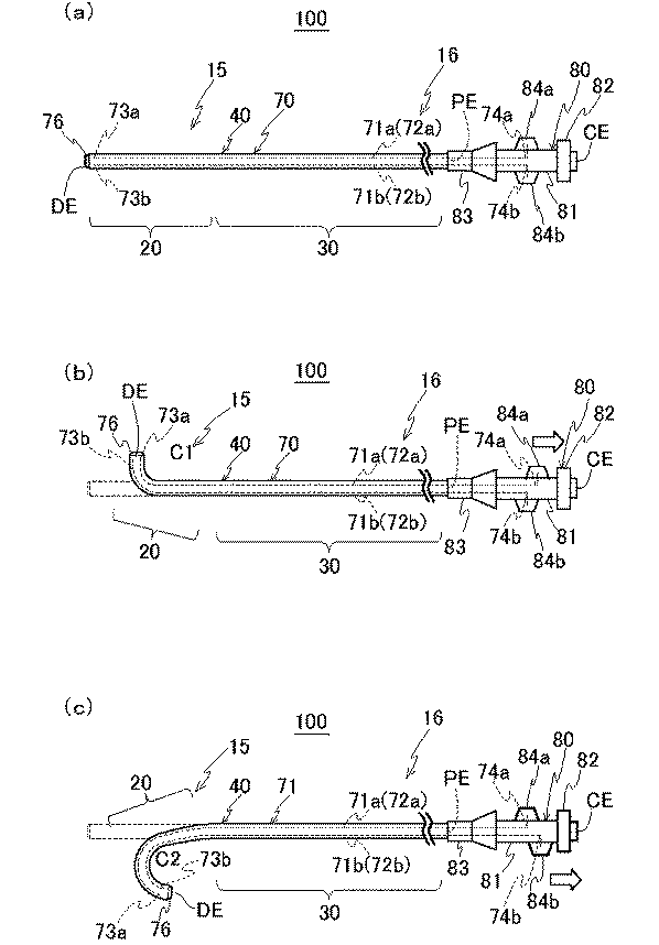
次に、図4を用いて、上述のように形成した管状本体10を用いたカテーテル100の構成について説明する。本実施形態のカテーテル100は、メインルーメン(図示せず)と、内部にメインルーメンを有する内層76と、内層76の外周表面に、上述の管状本体300からなる補強層(図示せず)と、補強層を含む内層76を被覆する外層(図示せず)と、外層の表面を被覆するコート層(図示せず)と、を有するシース70を有している。また、内層76の遠位端側DEには、白金等で形成されたリング状のマーカ(図示せず)が配置され、外層内に、メインルーメンよりも小径でメインルーメンの周囲に180度間隔で対向して配置された一対のサブルーメン71a、71bが設けられている。
Next, the configuration of the
また、サブルーメン71a、71bには、2本の操作線(第一操作線72aおよび第二操作線72b)が、それぞれ摺動可能に挿通されている。第一、第二操作線72a、72bは、カテーテル100の遠位端側DEであってマーカに、先端(以下、「遠位端73(73a、73b)」と呼ぶ。)が固定されている。また、各操作線72a、72bの他方の先端(以下、「近位端74(74a、74b)」と呼ぶ。)が近位端部16に固定され、この近位端部16を牽引することにより、図4(b)、(c)のように、カテーテル100の遠位端部15において、第一コイル20部分が屈曲する。
Further, two operation lines (
なお、カテーテル100の遠位端部15とは、カテーテル100の遠位端側DEを含む所定の長さ領域をいう。同様に、カテーテル100の近位端部16とは、カテーテル100の近位端側PEを含む所定の長さ領域をいう。また、カテーテル100が屈曲するとは、カテーテル100の一部または全部が、湾曲または折れ曲がって曲がることをいう。そして、本実施形態のカテーテル100は、牽引する操作線(第一操作線72aまたは第二操作線72b)の選択により、図4に示すように、第一コイル20が配置されていることで屈曲する遠位端部15の曲率C(C1、C2)が複数通りに変化する。この屈折の詳細については、後述する。
The
また、カテーテル100には、第一操作線72aおよび第二操作線72bを個別に牽引してカテーテル100の遠位端部15を屈曲させる操作部80が、カテーテル100の近位端部16に設けられている。
Further, the
操作部80は、カテーテル100の長手方向に延びる軸部81と、軸部81に対してカテーテル100の長手方向にそれぞれ進退するスライダ84a、84bと、軸部81を軸回転するハンドル部82と、シース70が回転可能に挿通された把持部83とを備えている。また、シース70の近位端部16は軸部81に固定されている。また、ハンドル部82と軸部81とは一体に構成されている。そして、把持部83とハンドル部82とを相対的に軸回転させることで、操作線72a、72bを含むシース70全体が軸部81とともにトルク回転する。近位端部16には剛性の高い第二コイル30が配置されているので、トルク伝達性に優れ、良好なトルク回転が可能となる。
The
したがって、本実施形態の操作部80は、シース70の遠位端部15を回転操作する部材である。なお、本実施形態においては、シース70をトルク回転させる回転操作部としてのハンドル部82と、シース70を屈曲させるための屈曲操作部としてのスライダ84とが一体に設けられている。
Therefore, the
第一操作線72aの近位端74aは、シース70の近位端部16から基端側に突出し、操作部80のスライダ84aに接続されている。また、第二操作線72bの近位端74bも同様に、操作部80のスライダ84bに接続されている。そして、スライダ84aとスライダ84bを軸部81に対して個別に基端側にスライドさせることにより、これに接続された第一操作線72aまたは第二操作線72bが牽引され、シース70の遠位端部15に引張力が与えられる。これにより、牽引された当該操作線72a、72bの側に第一コイル20が配置された遠位端部15が屈曲する。
The
ここで、シース70の各部の材料について説明する。上記内層76の材料としては、たとえば、フッ素系の熱可塑性ポリマーを用いることができる。より具体的には、ポリテトラフルオロエチレン(PTFE)やポリビニリデンフルオライド(PVDF)、ペルフルオロアルコキシフッ素樹脂(PFA)などの樹脂材料を用いることができる。このように、内層76にフッ素系樹脂を用いることにより、カテーテル100のメインルーメンを通じて造影剤や薬液などを患部に供給する際のデリバリー性が良好となる。
Here, the material of each part of the
上記外層の材料としては、たとえば、熱可塑性ポリマーが広く用いられる。一例として、PI、PAI、PETのほか、ポリエチレン(PE)、ポリアミド(PA)、ナイロンエラストマー、ポリウレタン(PU)、エチレン−酢酸ビニル樹脂(EVA)、ポリ塩化ビニル(PVC)またはポリプロピレン(PP)などの樹脂材料を用いることができる。 For example, a thermoplastic polymer is widely used as the material of the outer layer. Examples include PI, PAI, PET, polyethylene (PE), polyamide (PA), nylon elastomer, polyurethane (PU), ethylene-vinyl acetate resin (EVA), polyvinyl chloride (PVC), polypropylene (PP), etc. These resin materials can be used.
また、必要に応じて、外層の表面にコート層(図示せず)が設けられるが、当該コート層の材料としては、たとえば、ポリビニルアルコール(PVA)やポリビニルピロリドンなどの親水性の樹脂材料を用いることができる。 In addition, a coat layer (not shown) is provided on the surface of the outer layer as necessary. As the material of the coat layer, for example, a hydrophilic resin material such as polyvinyl alcohol (PVA) or polyvinyl pyrrolidone is used. be able to.
操作線(第一操作線72aおよび第二操作線72b)をサブルーメン71a、71bにそれぞれ挿通する方法は、種々の方法を採用することができる。予めサブルーメン71a、71bが貫通して形成されたカテーテル100のシース70に対して、その一端側から第一、第二操作線72a、72bを挿通してもよい。または、シース70の押出成形時に、樹脂材料と共に第一、第二操作線72a、72bを押し出してサブルーメン71a、71bの内部に挿通してもよい。
Various methods can be adopted as the method of inserting the operation lines (the
操作線72a、72bを樹脂材料と共に押し出してサブルーメン71a、71bに挿通する場合、操作線72a、72bには、シース70を構成する樹脂材料の溶融温度以上の耐熱性が求められる。かかる操作線72a、72bの場合、具体的な材料としては、たとえば、ポリエーテルエーテルケトン(PEEK)、ポリフェニレンスルフィド(PPS)、ポリブチレンテレフタレート(PBT)、PIもしくはPTFEなどの高分子ファイバー、または、SUS、耐腐食性被覆した鋼鉄線、チタンもしくはチタン合金などの金属線を用いることができる。一方、予め成形されたシース70のサブルーメン71a、71bに対して操作線72a、72bを挿通する場合など、操作線72a、72bに耐熱性が求められない場合は、上記各材料に加えて、PVDF、高密度ポリエチレン(HDPE)またはポリエステルなどを使用することもできる。
When the
なお、サブルーメン71a、71bは、本実施形態では、外層の内部に一対形成されている。そして、本実施形態のカテーテル100において、操作線72a、72bがそれぞれ挿通されたサブルーメン71a、71bは、補強層としての管状本体10の外側に形成されている。また、サブルーメン71a、71bはカテーテル100の長手方向(図4の紙面左右方向)に沿って設けられ、少なくともカテーテル100の近位端部16が開口している。このように、本実施形態および以降の実施形態では、サブルーメン71a、71bを、管状本体300の外側に形成しているが、本発明がこれに限定されるわけではない。たとえば、サブルーメン71a、71bを内層76の外側に形成した後、サブルーメン71a、71bの外周に管状本体10を配置形成してもよい。
In the present embodiment, a pair of
ここで、操作線72a、72bを挿通するサブルーメン71a、71bをメインルーメンと離間して設けることにより、メインルーメンを通じて薬剤等を供給したり光学系を挿通したりする際に、これらがサブルーメン71a、71bに脱漏することがない。そして、本実施形態のようにサブルーメン71a、71bを管状本体10の外部に設けることにより、シース70内を摺動する操作線72a、72bに対して、管状本体10の内部、すなわちメインルーメンが保護される。このため、かりに操作線72a、72bがカテーテル100の遠位端部15から外れたとしても、操作線72a、72bがメインルーメンの周壁を開裂してしまうことがない。
Here, the sub-lumens 71a and 71b through which the
操作線72a、72bの遠位端73a、73bは、カテーテル100の遠位端部15に固定されている。操作線72a、72bの遠位端73a、73bを遠位端部15に固定する態様は特に限定されない。本実施形態では、前述したように、操作線72a、72bの遠位端73a、73bをマーカに締結している。または、シース70の遠位端部15に溶着してもよく、あるいは、接着剤によりマーカまたはシース70の遠位端部15に接着固定してもよい。
The distal ends 73 a and 73 b of the operation lines 72 a and 72 b are fixed to the
上述のような操作線(第一操作線72aまたは第二操作線72b)の近位端74a、74b側を牽引すると、カテーテル100の遠位端部15に引張力が与えられて、当該操作線72a、72bが挿通されたサブルーメン71a、71bの側に向かって第一コイル20が配置された遠位端部15の一部または全部が屈曲する。一方、操作線72a、72bの近位端74a、74b側をカテーテル100に対して押し込んだ場合には、当該操作線72a、72bからカテーテル100の遠位端部15に対して押込力が実質的に与えられることはない。
When the
なお、本実施形態のカテーテル100では、牽引する操作線を、第一操作線72aのみとするか、第二操作線72bのみとするか、または2本の操作線72a、72bを同時に牽引するかにより、屈曲する遠位端部15の曲率Cが複数通りに変化する。これにより、さまざまな角度に分岐する体腔に対してカテーテル100を自在に進入させることができる。
In the
また、本実施形態のカテーテル100は、図4に示すように、2本の操作線(第一操作線72aまたは第二操作線72b)の近位端74a、74bをそれぞれ個別に牽引した場合の遠位端部15の曲率(C1、C2)が互いに相違する。具体的には、図4(b)、(c)に示すように、第一操作線72aを牽引した場合の遠位端部15の曲率C1に比べて、第二操作線72bを大きく牽引した場合の遠位端部15の曲率C2は、より大きくなる。
Further, as shown in FIG. 4, the
以下、本実施形態のカテーテル100の代表的な寸法について説明する。メインルーメンの半径は200〜300μm程度、内層76の厚さは10〜30μm程度、外層の厚さは100〜150μm程度、補強層としての管状本体10の厚さは20〜100μmとすることが好ましい。そして、カテーテル100の軸心からサブルーメン71a、71bの中心までの長さは300〜400μm程度、サブルーメン71a、71bの内径は40〜100μmとし、操作線72a、72bの太さを30〜60μmとすることが好ましい。そして、カテーテル100の最外径を350〜450μm程度とすることが好ましい。
Hereinafter, typical dimensions of the
すなわち、本実施形態のカテーテル100の外径は直径1mm未満とするのが好ましく、腹腔動脈などの血管に挿通可能である。また、本実施形態のカテーテル100に関しては、操作線72a、72bの牽引により進行方向が自在に操作されるため、たとえば分岐する血管内においても所望の方向にカテーテル100を進入させることが可能である。
That is, the outer diameter of the
また、管状本体10の柔軟性に優れる第一コイル20の存在により、遠位端部15を急角度で屈曲させても、メインルーメンが潰れる、カテーテル100が二つ折りに折れ曲がる、などの問題が発生するのを防止することができる。そのため、メインルーメンの内腔の平滑性を保持することができ、造影剤、薬液、内視鏡などを患部に円滑に供給することができる。
In addition, the presence of the
以上が本実施形態にかかるカテーテル100の動作例である。ここで、管状本体10の第一コイル20は、柔軟性に優れるよう形成しているため、屈曲性には優れるが、管材料に比べてトルク伝達性が低い。しかし、本実施形態では、前述したように、管状本体10の手元操作側に密巻きの第二コイル30を配置しているため、剛性に優れている。そのため、柔軟な屈曲性は損なうことなく、トルク伝達性にも優れたカテーテル100を実現することができる。したがって、さまざまな分岐角度で分岐する血管枝に対して本実施形態のカテーテル100を自在に進入させることができ、血管選択性に優れるカテーテル100を提供することができる。さらに、第二コイル30は、連結部40側にテーパー部32を形成しているので、第一コイル20との一体的で滑らかな連結が可能となる。そのため、体腔内の内壁への引っかかりや折れ曲がり等を防止して、体腔内での円滑な操作が可能となる。
The above is an operation example of the
また、上記実施形態では、管状本体10は、第一コイル20と、第二コイル30とを連結部40を介して連結しているが、本発明がこれに限定されるものではない。たとえば、第一コイルの第二コイルとの連結部とは反対側の他端、または、第二コイルの第一コイルとの連結部とは反対側の他端、もしくは、第一コイルと第二コイルとの間に、さらに第三コイルが、第二の連結部を介して連結され、互いに隣接するコイル層のうち、外径の大径なコイル層の連結部または第二の連結部側に各々テーパー部が形成されていてもよい。さらには、第四コイル以上のコイルが第三以上の連結部を介して連結されていてもよい。
Moreover, in the said embodiment, although the tubular
また、第三コイル以上のコイルを使用した場合、各コイルは、次第に直径が大径となるよう連結してもよいし、次第に直径が小径となるように連結してもよい。または、大径のコイル同士を小径のコイルで連結してもよい。いずれの場合でも、大径側のコイルの連結部側の先端をテーパー状に形成することにより、様々な線径または管径のコイルを円滑に連結することができる。そして、柔軟性に富むコイルと剛性に富むコイルとを組み合わせる、柔軟性や剛性が次第に異なるようにコイルを組み合わせる等することにより、機械的特性の異なる、バリエーションに富んだ管状本体を得ることができる。なお、他の実施形態でも同様に、第三以上コイルを連結してもよい。 Moreover, when the coil more than a 3rd coil is used, each coil may be connected so that a diameter may become a large diameter gradually, and you may connect so that a diameter may become a small diameter gradually. Alternatively, large-diameter coils may be connected by a small-diameter coil. In any case, coils with various wire diameters or tube diameters can be smoothly connected by forming the tip on the connecting portion side of the large diameter coil in a tapered shape. And, by combining a coil rich in flexibility and a coil rich in rigidity, or by combining coils so that flexibility and rigidity gradually differ, it is possible to obtain a tubular body rich in variations with different mechanical characteristics. . In other embodiments as well, a third or more coil may be connected.
例えば、遠位端部に剛性が高く耐圧性等に優れた第一コイルを配置すれば、血流や体腔壁面との接触で押し潰される等することがなく、体腔内への挿入と進行が容易となる。この第一コイルに連結する第二コイルが、屈曲性に優れている場合は、たとえば、さまざまに分岐する血管の形状に追随して第二コイルを容易に屈曲させ、血管選択性に優れる挿通が可能となる。また、柔軟性に優れているため、耐キンク性にも優れ、カテーテルの内腔が潰れるのを防止するとともに、屈曲しても元の形状に復元して、他の方向や曲率で自在に屈曲させることができる。さらに、手元操作側の第三コイルとして、密巻きで剛性に優れるコイルを使用することにより、カテーテルの円滑な進行が可能であるとともに、トルク伝達性に優れ、カテーテルを所望の方向に迅速かつ正確に回転させることができる。 For example, if a first coil with high rigidity and excellent pressure resistance is arranged at the distal end, it will not be crushed by contact with the blood flow or the body cavity wall surface, and insertion and progression into the body cavity will not occur. It becomes easy. If the second coil connected to the first coil is excellent in flexibility, for example, the second coil can be easily bent following the shape of a blood vessel that branches variously, and insertion with excellent blood vessel selectivity is achieved. It becomes possible. In addition, because it is excellent in flexibility, it also has excellent kink resistance, prevents the catheter lumen from collapsing, and even if it is bent, it can be restored to its original shape and bent freely in other directions and curvatures Can be made. Furthermore, by using a tightly wound and rigid coil as the third coil on the hand-operated side, the catheter can be smoothly advanced and has excellent torque transmission, and the catheter can be moved quickly and accurately in the desired direction. Can be rotated.
また、たとえば、管状本体10のコイルの種類を変えるだけでなく、シース70の遠位端部15、近位端部16、その中間部の内層76または外層を、それぞれ異なる樹脂材料で形成し、それぞれの部位の剛性や屈曲性を変化させてもよい。また、管状本体10の第一コイル20の巻回ピッチを変えることにより、それぞれの部位の剛性や屈曲性を変化させてもよい。
Further, for example, not only the type of the coil of the
また、本実施形態では、シース70に一対(二個)のサブルーメン71a、71bを180度間隔に対向して設けて、それぞれに操作線72a、72bを挿通しているが、本発明がこれに限定されるものではない。シース70に三個以上のサブルーメンを等角度間隔に設けてもよい。たとえば、三個のサブルーメンを等角度間隔(120度間隔)に設けた場合、3本の操作線を操作することにより、トルク伝達性に優れ、しかも目的方向に微細な角度で遠位端部を屈曲させることが可能となる。また、三個以上のサブルーメンを周方向にランダムに設けてもよい。このように、ランダムに設けるとは、上記のように正確な等角度間隔に設けるのではなく、周方向に全体的に分散していれば、多少の角度のズレを生じてもよいという意味である。いずれの場合でも、任意の一本または二本以上の操作線を選択して牽引することにより、当該操作線の方向、または当該二本以上の操作線の中間方向にシース70を屈曲させることができる。
In the present embodiment, a pair (two) of
以上のように、本実施形態のカテーテル100では、遠位端部15の先端は耐圧性や剛性に優れ、血管への侵入性が良好で、遠位端部15の先端以外は柔軟で屈曲性に優れ、近位端部16は剛性が高く、しかも近位端部から遠位端部へのトルク伝達性に優れるなど、遠位端部と近位端部とで異なる機械的特性を持たせることが容易かつ自在に実現可能となる。その結果、たとえば、さまざまな角度に分岐する血管等に対して自在に進入させることのできる、血管選択性に優れるカテーテルを提供することができる。
As described above, in the
また、上記実施形態は、カテーテルについて実施しているが、本発明は上述の実施形態に限定されるものではなく、ガイドワイヤ、内視鏡、超音波器具など、体腔内に挿入して使用する、他の長尺な医療機器にも適用することができる。以下の第二実施形態についても同様である。 Moreover, although the said embodiment is implemented about the catheter, this invention is not limited to the above-mentioned embodiment, It uses by inserting in a body cavity, such as a guide wire, an endoscope, and an ultrasonic instrument. It can also be applied to other long medical devices. The same applies to the following second embodiment.
<第二実施形態>
次に、図5を用いて、第二実施形態にかかる医療機器に用いられる管状本体210およびその製造工程について説明する。上記第一実施形態では、第一または第二コイル20、30の線材料21、31の巻きを互いに溶融接合して連結している。しかし、本実施形態では、図5(a)の状態では、互いの端部の位置や径が不揃いで、連結が困難である。そのため、本実施形態のテーパー部形成工程では、第一、第二コイル220、230の端部を溶融して研磨することで、平坦な端面222a、232aを形成し、当該端面222a、232aを互いに蝋材250により蝋付けして連結する連結工程と、蝋付けされた連結部240の蝋材250とともに第二コイル230を研削して、テーパー部232を形成する研削工程とを行っている。
<Second embodiment>
Next, the tubular
以下、詳細に説明する。図5(a)に示すように、本実施形態では、線材料221を巻回形成した第一コイル220および当該線材料221よりも直径が大径の線材料231を巻回形成した第二コイル230を用いている。そして、図5(b)に示すように、まず、溶融工程により、網がけ部分で示すように、第一、第二コイル220、230の互いの当接側を溶融して溶融部223、233を形成する。なお、第一、第二コイル220、230の端部の溶融は、レーザ照射、加熱、抵抗溶接等により行うことができる。この際に、溶融部223、233を研磨して平坦化することにより、連結し易い平坦な端面222a、232aを得るとともに、溶融部223、233部分で、管状本体10の硬度や柔軟性、耐キンク性等が急激に変化するのを防止している。また、溶融により、外径方向に材料が盛り上がるなど、厚肉になった場合は、溶融部の外径側も均一となるよう研磨してもよい。
Details will be described below. As shown in FIG. 5A, in this embodiment, the
次に、図5(b)に示すように、第一、第二コイル220、230の溶融部223、233の端面222a、232aを接合するが、その際に、より強固な連結を可能とするため、当該端面222a、232a間に蝋材250を配置している。この蝋材250は、少なくとも第二コイル230の溶融部233の外径と同一またはそれ以上の外径のものを用いるのが好ましい。そして、端面222a、232aおよび蝋材250を当接した状態で、周方向をレーザ照射、加熱、抵抗溶接等により、互いを溶融接合する。この工程により、蝋材250を介して、第一、第二コイル220、230の端面222a、232aが強固に連結した連結部240が得られる。
Next, as shown in FIG. 5 (b), the
次に、第一コイル220の端面222aよりも大径な蝋材250と第二コイル230の連結部240側の端部をともに研削して、テーパー部232を形成している。このようなテーパー部形成工程で形成されたテーパー部232は、蝋材250の介在により、連結部240に隙間等があっても、その隙間が蝋材250で埋められる、連結部240の連結強度を向上できる、等の効果を得ることができる。
Next, the
なお、蝋材250の材料としては、医療機器に用いることを考慮して、銀蝋を用いるのが好ましい。しかし、本発明がこれに限定されるものではなく、医療機器の用途に応じて、廉価な半田等を用いてもよい。また、本実施形態では、加熱により端面222a、232aを連結しているが、抵抗溶接やレーザにより連結を行ってもよい。
Note that it is preferable to use silver wax as the material of the
なお、本発明は上述の実施形態に限定されるものではなく、本発明の目的が達成される限りにおける種々の変形、改良等の態様も含む。 The present invention is not limited to the above-described embodiment, and includes various modifications and improvements as long as the object of the present invention is achieved.
10、110、210 管状本体
20、120、220 第一コイル
21、121、221 線材料(第一コイル)
30、130、230 第二コイル
31、131、231 線材料(第二コイル)
32、132、232 テーパー部
32a、32b、32c、32d、32e テーパー面
40、140、240 連結部
76 内層
100 カテーテル(医療機器)
222a、223a 端面
250 蝋材
10, 110, 210
30, 130, 230
32, 132, 232
222a, 223a
Claims (16)
前記管状本体が、
線材料を巻回して形成された第一コイルと、当該第一コイルの前記線材料よりも直径が大径の線材料を巻回して形成された第二コイルと、を有し
前記第一コイルと前記第二コイルとが連結部を介して連結され、
前記第二コイルは、前記連結部側の端部に、当該連結部方向に向かって次第に小径となる所定長さのテーパー部を有し、
当該テーパー部は、前記第二コイルの外周表面が削られ、隣接する巻き同士の断面積が前記連結部方向に向かって次第に狭小となるよう形成されている医療機器。 A medical device that is used by being inserted into a body cavity and has a long tubular body having flexibility,
The tubular body is
A first coil formed by winding a wire material; and a second coil formed by winding a wire material having a diameter larger than that of the wire material of the first coil. And the second coil are connected via a connecting portion,
The second coil has a tapered portion of a predetermined length that gradually becomes smaller in diameter toward the connecting portion at the end on the connecting portion side,
The taper portion is a medical device in which the outer peripheral surface of the second coil is cut so that the cross-sectional area between adjacent windings gradually becomes narrower in the direction of the connecting portion.
1.0 < t ≦ 2.0
の条件を満たす請求項1に記載の医療機器。 When the ratio of the diameter d B of the wire material of the second coil to the diameter d A of the wire material of the first coil is t, the following expression 1.0 <t ≦ 2.0
The medical device of Claim 1 which satisfy | fills these conditions.
0.5 ≦ Ipbt/Ipa ≦ 2.0
の条件を満たす請求項1または2に記載の医療機器。 When the cross-sectional secondary pole moment of the wire material of the first coil is I pa and the cross-sectional secondary pole moment of the wire material at the tip of the tapered portion of the second coil is I pbt , the following formula 0.5 ≦ I pbt / I pa ≦ 2.0
The medical device of Claim 1 or 2 which satisfy | fills these conditions.
0.5 ≦ hB/dB < 1.0
の条件を満たす請求項1から3のいずれか一項に記載の医療機器。 The diameter of the wire material of said second coil and d B, when the cross-sectional center height of the wire material of the wound portion of the end portion of the connecting portion side of the tapered portion was h B, the following equation 0.5 ≦ h B / d B <1.0
The medical device as described in any one of Claim 1 to 3 which satisfy | fills these conditions.
内部に前記メインルーメンを有する内層と、
前記内層の外周表面に、前記管状本体からなる補強層と、
少なくとも前記補強層を含む前記内層を被覆する外層と、を有するカテーテルである請求項1から11のいずれか一項に記載の医療機器。 The main lumen,
An inner layer having the main lumen inside;
On the outer peripheral surface of the inner layer, a reinforcing layer made of the tubular body,
The medical device according to any one of claims 1 to 11, which is a catheter having at least an outer layer that covers the inner layer including the reinforcing layer.
前記第二コイルの前記連結部側の端部に、当該連結部方向に向かって次第に小径となるテーパー部を所定長さで形成するテーパー部形成工程と、を含む医療機器の製造方法。 A first coil formed by winding a wire material and a second coil formed by winding a wire material having a diameter larger than that of the wire material of the first coil are connected via a connecting portion, A connecting step for forming a tubular body extending in the longitudinal direction;
A method of manufacturing a medical device, comprising: a tapered portion forming step of forming a tapered portion having a gradually decreasing diameter toward the connecting portion in a predetermined length at an end of the second coil on the connecting portion side.
Priority Applications (1)
| Application Number | Priority Date | Filing Date | Title |
|---|---|---|---|
| JP2011053117A JP2012187263A (en) | 2011-03-10 | 2011-03-10 | Medical device and method for producing the same |
Applications Claiming Priority (1)
| Application Number | Priority Date | Filing Date | Title |
|---|---|---|---|
| JP2011053117A JP2012187263A (en) | 2011-03-10 | 2011-03-10 | Medical device and method for producing the same |
Publications (1)
| Publication Number | Publication Date |
|---|---|
| JP2012187263A true JP2012187263A (en) | 2012-10-04 |
Family
ID=47081089
Family Applications (1)
| Application Number | Title | Priority Date | Filing Date |
|---|---|---|---|
| JP2011053117A Pending JP2012187263A (en) | 2011-03-10 | 2011-03-10 | Medical device and method for producing the same |
Country Status (1)
| Country | Link |
|---|---|
| JP (1) | JP2012187263A (en) |
Cited By (4)
| Publication number | Priority date | Publication date | Assignee | Title |
|---|---|---|---|---|
| JP2018516128A (en) * | 2015-05-29 | 2018-06-21 | コヴィディエン リミテッド パートナーシップ | Tapering outer diameter catheter |
| US10357631B2 (en) | 2015-05-29 | 2019-07-23 | Covidien Lp | Catheter with tapering outer diameter |
| US10398874B2 (en) | 2015-05-29 | 2019-09-03 | Covidien Lp | Catheter distal tip configuration |
| US11219740B2 (en) | 2015-05-29 | 2022-01-11 | Covidien Lp | Catheter including tapering coil member |
Citations (9)
| Publication number | Priority date | Publication date | Assignee | Title |
|---|---|---|---|---|
| JPS62363A (en) * | 1985-04-18 | 1987-01-06 | アドヴアンスド カ−デイオヴアスキユラ− システムズ インコ−ポレ−テツド | Guide wire |
| JPH02104370A (en) * | 1987-11-27 | 1990-04-17 | Boston Scient Corp | Medical guide wire |
| JPH07323090A (en) * | 1994-05-31 | 1995-12-12 | Terumo Corp | Medical tube |
| JP2002539901A (en) * | 1999-03-29 | 2002-11-26 | クック インコーポレイティド | Guide wire |
| JP2004275200A (en) * | 2003-03-12 | 2004-10-07 | Terumo Corp | Catheter |
| JP2005296078A (en) * | 2004-04-06 | 2005-10-27 | Asahi Intecc Co Ltd | Medical tools |
| JP2006174959A (en) * | 2004-12-21 | 2006-07-06 | Asahi Intecc Co Ltd | Catheter and manufacturing method thereof |
| JP2006519069A (en) * | 2003-02-26 | 2006-08-24 | ボストン サイエンティフィック リミテッド | Long-body medical device |
| JP2007512914A (en) * | 2003-12-02 | 2007-05-24 | ボストン サイエンティフィック リミテッド | Composite medical device and formation method |
-
2011
- 2011-03-10 JP JP2011053117A patent/JP2012187263A/en active Pending
Patent Citations (9)
| Publication number | Priority date | Publication date | Assignee | Title |
|---|---|---|---|---|
| JPS62363A (en) * | 1985-04-18 | 1987-01-06 | アドヴアンスド カ−デイオヴアスキユラ− システムズ インコ−ポレ−テツド | Guide wire |
| JPH02104370A (en) * | 1987-11-27 | 1990-04-17 | Boston Scient Corp | Medical guide wire |
| JPH07323090A (en) * | 1994-05-31 | 1995-12-12 | Terumo Corp | Medical tube |
| JP2002539901A (en) * | 1999-03-29 | 2002-11-26 | クック インコーポレイティド | Guide wire |
| JP2006519069A (en) * | 2003-02-26 | 2006-08-24 | ボストン サイエンティフィック リミテッド | Long-body medical device |
| JP2004275200A (en) * | 2003-03-12 | 2004-10-07 | Terumo Corp | Catheter |
| JP2007512914A (en) * | 2003-12-02 | 2007-05-24 | ボストン サイエンティフィック リミテッド | Composite medical device and formation method |
| JP2005296078A (en) * | 2004-04-06 | 2005-10-27 | Asahi Intecc Co Ltd | Medical tools |
| JP2006174959A (en) * | 2004-12-21 | 2006-07-06 | Asahi Intecc Co Ltd | Catheter and manufacturing method thereof |
Cited By (5)
| Publication number | Priority date | Publication date | Assignee | Title |
|---|---|---|---|---|
| JP2018516128A (en) * | 2015-05-29 | 2018-06-21 | コヴィディエン リミテッド パートナーシップ | Tapering outer diameter catheter |
| US10357631B2 (en) | 2015-05-29 | 2019-07-23 | Covidien Lp | Catheter with tapering outer diameter |
| US10398874B2 (en) | 2015-05-29 | 2019-09-03 | Covidien Lp | Catheter distal tip configuration |
| US11219740B2 (en) | 2015-05-29 | 2022-01-11 | Covidien Lp | Catheter including tapering coil member |
| US11623067B2 (en) | 2015-05-29 | 2023-04-11 | Covidien Lp | Catheter |
Similar Documents
| Publication | Publication Date | Title |
|---|---|---|
| JP7266407B2 (en) | CATHETER AND CATHETER MANUFACTURING METHOD | |
| JP5929315B2 (en) | Medical device and method for manufacturing medical device | |
| JP4981471B2 (en) | Guide wire | |
| US20210268228A1 (en) | Catheter devices and methods for making them | |
| WO2013146673A1 (en) | Medical instrument and method for manufacturing medical instrument | |
| WO2014162393A1 (en) | Guide wire | |
| JP2012213478A (en) | Medical instrument | |
| JP5927974B2 (en) | Medical equipment | |
| JP5742238B2 (en) | Medical equipment | |
| JP2013180156A (en) | Medical equipment | |
| JP2012213627A (en) | Catheter | |
| JP2020508151A (en) | Flexible torque cable for delivery of medical devices | |
| JP2012187263A (en) | Medical device and method for producing the same | |
| JP2012213507A (en) | Medical instrument | |
| JP6089876B2 (en) | Medical equipment | |
| JP6089864B2 (en) | Medical device and method for manufacturing medical device | |
| WO2019004100A1 (en) | Catheter, separator, and suction system | |
| WO2014157253A1 (en) | Medical device and medical device production method | |
| JP6205785B2 (en) | Medical equipment | |
| JP2014018390A (en) | Catheter and method for manufacturing the same | |
| JP2013158588A (en) | Medical coil, medical device and method for producing medical coil | |
| JP2013192692A (en) | Medical coil, medical instrument and method for manufacturing medical coil | |
| JP6201368B2 (en) | Medical equipment | |
| US20210290915A1 (en) | Guide wire | |
| JP6319390B2 (en) | Medical device and method for manufacturing medical device |
Legal Events
| Date | Code | Title | Description |
|---|---|---|---|
| A621 | Written request for application examination |
Free format text: JAPANESE INTERMEDIATE CODE: A621 Effective date: 20140108 |
|
| A977 | Report on retrieval |
Free format text: JAPANESE INTERMEDIATE CODE: A971007 Effective date: 20141024 |
|
| A131 | Notification of reasons for refusal |
Free format text: JAPANESE INTERMEDIATE CODE: A131 Effective date: 20141104 |
|
| A521 | Written amendment |
Free format text: JAPANESE INTERMEDIATE CODE: A523 Effective date: 20141225 |
|
| A02 | Decision of refusal |
Free format text: JAPANESE INTERMEDIATE CODE: A02 Effective date: 20150203 |