JP2010509640A - Compound liquid lens and optical device incorporating the same - Google Patents
Compound liquid lens and optical device incorporating the same Download PDFInfo
- Publication number
- JP2010509640A JP2010509640A JP2009536271A JP2009536271A JP2010509640A JP 2010509640 A JP2010509640 A JP 2010509640A JP 2009536271 A JP2009536271 A JP 2009536271A JP 2009536271 A JP2009536271 A JP 2009536271A JP 2010509640 A JP2010509640 A JP 2010509640A
- Authority
- JP
- Japan
- Prior art keywords
- lens
- liquid
- liquid lens
- liquids
- immiscible
- Prior art date
- Legal status (The legal status is an assumption and is not a legal conclusion. Google has not performed a legal analysis and makes no representation as to the accuracy of the status listed.)
- Pending
Links
- 239000007788 liquid Substances 0.000 title claims abstract description 156
- 230000003287 optical effect Effects 0.000 title claims abstract description 47
- 150000001875 compounds Chemical class 0.000 title 1
- 238000000034 method Methods 0.000 claims description 19
- 230000005684 electric field Effects 0.000 claims description 16
- 230000001902 propagating effect Effects 0.000 claims description 11
- 230000000694 effects Effects 0.000 claims description 5
- 239000004065 semiconductor Substances 0.000 claims description 5
- 238000006243 chemical reaction Methods 0.000 claims description 3
- 239000013078 crystal Substances 0.000 description 14
- 230000008859 change Effects 0.000 description 10
- 230000004044 response Effects 0.000 description 3
- 230000008878 coupling Effects 0.000 description 2
- 238000010168 coupling process Methods 0.000 description 2
- 238000005859 coupling reaction Methods 0.000 description 2
- 238000013461 design Methods 0.000 description 2
- 238000006073 displacement reaction Methods 0.000 description 2
- 230000004048 modification Effects 0.000 description 2
- 238000012986 modification Methods 0.000 description 2
- 239000000615 nonconductor Substances 0.000 description 2
- 238000005192 partition Methods 0.000 description 2
- 230000004043 responsiveness Effects 0.000 description 2
- 239000010409 thin film Substances 0.000 description 2
- 238000012937 correction Methods 0.000 description 1
- 230000007547 defect Effects 0.000 description 1
- 239000010408 film Substances 0.000 description 1
- 238000005259 measurement Methods 0.000 description 1
- 239000013307 optical fiber Substances 0.000 description 1
- 230000002093 peripheral effect Effects 0.000 description 1
- 230000000644 propagated effect Effects 0.000 description 1
- 238000001228 spectrum Methods 0.000 description 1
- 230000000087 stabilizing effect Effects 0.000 description 1
- 238000001429 visible spectrum Methods 0.000 description 1
Images


Classifications
-
- G—PHYSICS
- G02—OPTICS
- G02B—OPTICAL ELEMENTS, SYSTEMS OR APPARATUS
- G02B3/00—Simple or compound lenses
- G02B3/12—Fluid-filled or evacuated lenses
- G02B3/14—Fluid-filled or evacuated lenses of variable focal length
-
- G—PHYSICS
- G02—OPTICS
- G02B—OPTICAL ELEMENTS, SYSTEMS OR APPARATUS
- G02B26/00—Optical devices or arrangements for the control of light using movable or deformable optical elements
- G02B26/004—Optical devices or arrangements for the control of light using movable or deformable optical elements based on a displacement or a deformation of a fluid
- G02B26/005—Optical devices or arrangements for the control of light using movable or deformable optical elements based on a displacement or a deformation of a fluid based on electrowetting
Landscapes
- Physics & Mathematics (AREA)
- General Physics & Mathematics (AREA)
- Optics & Photonics (AREA)
- Mechanical Light Control Or Optical Switches (AREA)
- Optical Modulation, Optical Deflection, Nonlinear Optics, Optical Demodulation, Optical Logic Elements (AREA)
Abstract
本発明は、ビーム操舵と焦点調整を可能にする種々の構成の液体レンズを提供する。たとえば、本発明の一態様によれば、複数の不混和性のレンズ液体によって定義される第1および第2のレンズ面を通って延在する光伝播軸に沿って、光信号がレンズの入力側からレンズの出力側へと伝播するように、液体レンズは構成される。各可変焦点レンズ面は不混和液体間の界面に沿って形成され、外部信号により、レンズ面の形状を変化させることができる。レンズ面を形成する2つのレンズ部品は比較的ずらされた位置にあるため、レンズの焦点距離とビーム操舵はレンズ面の形状を変化させることによって調整することができる。さらなる実施形態は開示される。The present invention provides various configurations of liquid lenses that allow beam steering and focus adjustment. For example, according to one aspect of the invention, an optical signal is input to the lens along a light propagation axis extending through first and second lens surfaces defined by a plurality of immiscible lens liquids. The liquid lens is configured to propagate from the side to the output side of the lens. Each variable focus lens surface is formed along an interface between immiscible liquids, and the shape of the lens surface can be changed by an external signal. Since the two lens components forming the lens surface are at relatively shifted positions, the focal length of the lens and beam steering can be adjusted by changing the shape of the lens surface. Further embodiments are disclosed.
Description
本発明は、可変焦点液体レンズおよび可変焦点液体レンズを組み込んだ光学装置に関するものである。 The present invention relates to a variable focus liquid lens and an optical apparatus incorporating the variable focus liquid lens.
本発明の一実施の形態によれば、液体レンズは、このレンズの実質的に不混和性の第1、第2および第3の液体によって画成される第1および第2のレンズ面を通って延在する光伝播軸に沿って、光信号がレンズの入力側から出力側へ伝播することができるように構成される。このレンズには、第1の不混和液体が第2の不混和液体を介して第3の不混和液体と機械的に結合するように構成された液体タンクが含まれる。また、第1、第2および第3の不混和液体間の界面に沿って各レンズ面が形成される。 According to one embodiment of the present invention, the liquid lens passes through first and second lens surfaces defined by the substantially immiscible first, second and third liquids of the lens. The optical signal can be propagated from the input side to the output side of the lens along the light propagation axis extending in the direction. The lens includes a liquid tank configured to mechanically couple a first immiscible liquid with a third immiscible liquid via a second immiscible liquid. Each lens surface is formed along the interface between the first, second and third immiscible liquids.
本発明の別の実施形態によれば、第1および第2のレンズ面は、レンズの光伝播軸zに直交する方向xに沿って互いにずらされた位置に設けられる。また、さらに2つの不混和液体を加え、それらの界面に沿って形成される第3のレンズ面を提供し、この第3のレンズ面が、方向xと光伝播軸zとに直交する方向yに沿って、第1および第2のレンズ面の一方もしくは両方と、互いにずらされた位置にあるとしてもよい。 According to another embodiment of the present invention, the first and second lens surfaces are provided at positions shifted from each other along a direction x orthogonal to the light propagation axis z of the lens. Further, two additional immiscible liquids are added to provide a third lens surface formed along the interface between them, the third lens surface being a direction y orthogonal to the direction x and the light propagation axis z. And one or both of the first and second lens surfaces may be offset from each other.
本発明のさらに別の実施形態によれば、本発明による液体レンズを備えた光学系が提供される。液体レンズは、系内を伝播する伝播光に広範囲なビーム操舵効果を生み出す手法、または液体レンズの焦点距離を変化させる手法、あるいはこれら両手法により、この伝播光を導くよう系内に設定される。 According to yet another embodiment of the present invention, an optical system comprising a liquid lens according to the present invention is provided. The liquid lens is set in the system to guide this propagating light by a method that generates a wide beam steering effect on the propagating light propagating in the system, a method that changes the focal length of the liquid lens, or both methods. .
したがって本発明は、可変焦点液体レンズの設計改善と、このレンズを組み込むことによって改良された半導体レーザおよび他種のオプトメカニカルパッケージを提供することを目的とするものである。例えば、分布帰還型(DFB)レーザや分布ブラッグ反射型(DBR)レーザのような半導体レーザを、短波長光源を生成するために第2高調波発生(SHG)結晶のような光波長変換装置と組み合わせる場合、ビーム操舵を利用することに利点があるであろう。より詳しくは、SHG結晶はチューニングによって基本レーザ信号の高調波成分を生成するように設定することが可能であり、例えば1060nmのDFBもしくはDBRレーザの波長をSHG結晶のスペクトルの中心に合わせることにより、530nmの波長、すなわち可視スペクトルの緑色部分に変換することができる。本発明による可変焦点レンズは、レーザチップから光波長変換装置へと光を導くために配置できる。本発明の他の目的は、ここで具体化される本発明に関する記述から明らかになるであろう。 Accordingly, it is an object of the present invention to provide an improved design of a variable focus liquid lens and to provide an improved semiconductor laser and other types of optomechanical packages by incorporating this lens. For example, a semiconductor laser, such as a distributed feedback (DFB) laser or a distributed Bragg reflection (DBR) laser, and an optical wavelength converter, such as a second harmonic generation (SHG) crystal, to generate a short wavelength light source When combined, it may be advantageous to use beam steering. More specifically, the SHG crystal can be set to generate harmonic components of the fundamental laser signal by tuning, for example by matching the wavelength of a 1060 nm DFB or DBR laser to the center of the SHG crystal spectrum, It can be converted to a wavelength of 530 nm, ie the green part of the visible spectrum. The variable focus lens according to the present invention can be arranged to guide light from a laser chip to an optical wavelength converter. Other objects of the invention will become apparent from the description of the invention embodied herein.
以下に詳細に説明する本発明の具体的な実施の形態は、以下に示す図面と併せて読まれたときに最も理解できる。なお図面において、同等の構造物は同じ参照符号で表す。 The specific embodiments of the present invention described in detail below are best understood when read in conjunction with the following drawings. In the drawings, equivalent structures are denoted by the same reference numerals.
まず図1に、本発明の一実施の形態による液体レンズ10を示す。一般に、図1に示される液体レンズ10には第1および第2の液体レンズ部品12、14が備えられている。第1のレンズ部品12には、レンズ10の液体タンク20内に収容された第1および第2の不混和液体21、22の界面に沿う第1のレンズ面13が含まれる。同様に、第2のレンズ部品14には、液体タンク20内に収容された第2および第3の不混和液体22、23の界面に沿う第2のレンズ面15が含まれる。なお、本発明を定義し記述する上で、レンズ面を「含む」レンズ部品をここで参照するが、そのレンズ面の物理的な位置を限定するものと解釈されるべきではないことに留意されたい。むしろ、そのレンズ面の位置には関わらず、そのレンズ部品の一部であるものとして理解されるべきである。例えば図1および図2に示す本発明の実施形態において意図されているのは、第1のレンズ面13が第1のレンズ部品12の一部であることであり、レンズ面がどの程度まで第3の不混和液体23の方向に延伸しているかは問題ではない。
First, FIG. 1 shows a
第2の不混和液体22の屈折率と、第1および第3の各不混和液体21、23の屈折率とを異なるものとすることにより、第1および第2のレンズ面13、15はレンズ10に所望の光学効果を導くことができる。詳しくは、第1および第2のレンズ面13、15を通って延在する光伝播軸に沿って光信号がレンズ10の入力側からレンズ10の出力側へ伝播する場合、光学的に著しい信号変化を各レンズ面で導くために、各屈折率を十分に異なったものとすべきである。
By making the refractive index of the second
例えば、これに限定されるものではないが、レーザチップを備えた半導体レーザと、光波長変換装置と、本発明による液体レンズ10に関連し、レーザチップの光出力とPPLN波長変換結晶の入力の間の光路に沿って液体レンズ10を設置することができる。また、一対のコリメートレンズをさらに提供し、液体レンズ10をこのコリメートレンズ間の光路のコリメートされた部分に設置することが好ましい。レーザ出力とPPLN結晶との間の結合効率を向上させるため、液体レンズ10を、ここで記述する手法、すなわちPPLN結晶の入力面に対し伝播光の光路を再調整する手法、またはPPLN結晶の入力面において伝播光の焦点を調整する手法、あるいはこれら両手法によりチューニングするものとしてもよい。光信号に生じる変化は固定であってもよいが、本発明の種々の実施形態は、光学系における光信号の方向可変度を変化させることによるビーム操舵効果を生み出すのに特に適している。さらに、本発明の種々の実施形態は、レンズ10の焦点距離可変度を変化させることによって種々の焦点距離を提供するのに特に適している。
For example, but not limited to, a semiconductor laser with a laser chip, an optical wavelength converter, and a
具体的に、一例として図1を参照すると、第1および第3の不混和液体21、23を電気応答性の液体とすることが可能であり、レンズ10を、レンズ面13、15の一方もしくは両方の形状および/または向きを変えることができる電界をそれぞれ生成するように設定された制御電極30、32、34を有するものとしてもよい。図1に示すように、制御電極30、32、34は少なくとも部分的に液体タンク20の境界を成すように形成されてもよく、この場合、電極30および34は部分的に円錐状の壁部を有する。電気応答性のレンズ液体がタンクの円錐状壁と接続する角度、およびその液体がタンクの壁に沿って接触する地点は、制御電極に印加される制御電圧の関数である。このように、各レンズ面の形状および向きは、制御電極に印加される制御電圧の関数として制御することができる。
Specifically, referring to FIG. 1 as an example, the first and third
例えば、これに限定されるものではないが、電極と第1および第2のレンズ部品12、14の配置とが回転対称にある特定の場合、電極への電圧を変動させることで第1および第2のレンズ面13、15の曲率半径が変化し、この曲率の変化により第1および第2のレンズ部品12、14の焦点距離が変化する。図1に示すようにこれらのレンズを距離aだけ横方向にずらすと、レンズ部品12、14の曲率半径を変化させることによって、伝播する光信号の伝播方向を選択的に調整したり、レンズ10の焦点距離を調整したりすることが可能になる。レンズ部品12および14に異なる信号を印加することによって、ビーム焦点やビーム操舵を単独で調整することができる。例えば、以下の方程式は、レーザダイオードと、第1のコリメートレンズL1と、第1および第2のレンズ部品12、14を有する液体レンズ10と、第2のコリメートレンズL2と、PPLN結晶とを光路に沿って連続的に備えた光学的構成における、PPLN波長変換結晶入力面での光ビームスポットのビーム操舵およびビーム焦点の調整を示すものである。

ここで、DyはPPLN結晶入力面におけるビームスポットの横方向の変位、DzはPPLN結晶入力面におけるビームスポットの焦点の変位、f1およびf2は第1および第2の液体レンズ部品12、14の各焦点距離、そしてfL2は第2のコリメートレンズL2の焦点距離を示す。したがって、ビームスポットの横方向の位置は、和(1/f1+1/f2)を変えないようにf1とf2を変更することによって調整することができる。逆に、差(1/f1−1/f2)を一定に保ちながらf1とf2を調整することによって、焦点を変更することができる。
Here, D y is the lateral displacement of the beam spot on the PPLN crystal input surface, D z is the displacement of the focal point of the beam spot on the PPLN crystal input surface, and f 1 and f 2 are the first and second
図2は、本発明におけるレンズ面13、15の形状として意図される変形例を示したものである。この図において、制御電極30、32、34は円対称であり、曲率が変化したレンズ面13´、15´を生成するような電位を与えることができる。図3は、考えられる一例の、第1および第2のレンズ部品12、14のレンズ面の向きを変化させた例を示したものである。この図において、制御電極30、32、34は円対称ではなく、向きが変化したレンズ面13´、15´を生成するような電位を与えることができる。
FIG. 2 shows a modification intended as the shape of the
本発明の構想を用いて、実際には無制限のレンズ面の向きや形状の組合せを開示できると考えられる。例えば、各制御電極30、32、34を再分割し、個々に制御可能な複数の部品電極や電極部を含むようにすることができると考えられる。より詳しくは、制御電極30および34がそれぞれ連続する円錐状の電極を備え、制御電極32が連続する環状の電極を備え、各円錐状または環状の電極を、レンズ面13、15の制御を改善する複数の部品電極へと電極の円弧に沿って分割してもよいと考えられる。可変焦点液体レンズに使用される電極部品の例については米国特許第6,538,823号明細書に示されている。この特許の記述の中で、液体レンズ面の曲率を変化させるために可変焦点液体レンズ内の電極を用いる手法を理解するのに有用な部分のみが、参照により本書に組み込まれる。
Using the concept of the present invention, it is believed that in practice, unlimited combinations of lens surface orientations and shapes can be disclosed. For example, it is considered that each of the
本発明を記述し定義する上で、「電気応答性」を有する液体とは、導電性を有する液体や、限定された導電性を有する極性液体でもよく、あるいはここで述べたようにそれに対して電界や磁界を印加した際に、物理的に反応するように設計されたものであればいかなる液体であってもよいことに留意されたい。また、第2の不混和液体22と第1および第3の不混和液体21、23との間の機械的な結合の効力によって、第2の不混和液体22の形状と向きが、第1および第3の不混和液体21、23の形状と向きに影響することから、第2の不混和液体22のみを電気応答性を有する液体として提供することで十分であると考えることもできる。なお、レンズに供給される全ての不混和液体21、22、23を、電気応答性を有する液体としてもよい。
In describing and defining the present invention, an “electrically responsive” liquid may be a liquid having conductivity or a polar liquid having limited conductivity, or as described herein. It should be noted that any liquid that is designed to physically react when an electric or magnetic field is applied. In addition, the shape and orientation of the second
制御電極によって生成された電界をレンズ面13、15の形状や向きを変えるために使用する手法の詳細は本発明の範囲を超えたものであり、この手法については、容易に入手可能な種々の教示を用いることにより理解することができる。例えば、これらに限定されるものではないが、米国特許第6,538,823号、同第6,778,328号、同6,936,809号の各明細書により、この手法に関する詳しい説明が提供されている。これらの特許の記述の中で、凸レンズ面の曲率を変化させるために電界を用いる手法を理解するのに有用な部分のみが、参照により本書に組み込まれる。 Details of the technique used to change the shape and orientation of the lens surfaces 13, 15 are beyond the scope of the present invention for the electric field generated by the control electrode, and there are various readily available techniques for this technique. It can be understood by using the teaching. For example, but not limited to, U.S. Pat. Nos. 6,538,823, 6,778,328, and 6,936,809 provide a detailed explanation of this technique. Is provided. Of those patent descriptions, only those portions useful for understanding the technique of using an electric field to change the curvature of the convex lens surface are incorporated herein by reference.
本発明を実施する際には、第1および第2のレンズ面13、15それぞれの形状を独立して変化させることができる複数の異なる電界を発生させるために、適切な制御電子回路と、それぞれ独立して制御することができる電極30、32、34とを確実に提供することによって、操作の多用途性を最大にすることがしばしば好ましいと考えられる。この目的を達成するために、図1や他の図に示すレンズ10は、制御電極30、32、34間にそれぞれ電気絶縁体36を備えている。電気絶縁体36は、例えば図1に示すように、液体タンク20の境界を成すように設けてもよい。
In practicing the present invention, appropriate control electronics are provided to generate a plurality of different electric fields that can independently change the shape of each of the first and second lens surfaces 13, 15, respectively. It is often considered desirable to maximize the versatility of operation by reliably providing
本発明における一つの重要な態様を図6Aおよび6Bに示す。ここで、第1および第2のレンズ部品12、14の各位置は直交座標系XYZに関連して示されている。図6Aに示すように、第1および第2のレンズ部品の配置と、制御電極30、32、34による制御によって、各レンズ部品の対応するレンズ面13、15を方向xに沿って互いにずらされた位置になるように設けることができる。ここで方向xは、一般的な光伝播軸の方向を表す方向zに直交するものである。図6Bは、XY平面における各レンズ部品12、14のずらされた位置関係を概略的に示したものである。このようにずらされた位置関係とすることにより、ユーザがx方向に対して大きなビーム操舵を行う際に、比較的複雑でない構成の制御電極を用いて行うことが可能になる。
One important aspect of the present invention is shown in FIGS. 6A and 6B. Here, each position of the 1st and
図6Aおよび6Bにはまた、レンズ10にさらに設けられた液体タンク内に収容された第1および第2の不混和液体21、22の界面に沿う第3のレンズ面17を有する第3の液体レンズ部品16が示されている。第1のレンズ部品12の第1のレンズ面13は、第3のレンズ部品16の第3のレンズ面17に対し、方向xに直交する方向yに沿って、ずらされた位置にある。結果として、第3のレンズ面17の形状および/または向きを変えることによって、ユーザがy方向に対して大きなビーム操舵を行う際に、比較的複雑でない構造の制御電極を用いて行うことが可能になる。図6Aおよび6Bに示すように、レンズ部品を互いにずらされた位置関係とすることにより、これらを組み合わせて、レンズ10の焦点を変化させる上述の能力を維持しながら、XY平面上でのビーム操舵を便利に行うことが可能となる。
FIGS. 6A and 6B also show a third liquid having a
本出願の図1〜6に示す液体タンクに関し、レンズ面接触壁40は、円錐状や円筒状の壁の各内周面として形成することができると考えられる。しかしながら、種々の従来型タンクや今後開発され得るタンクの形状もまた、本発明のレンズ部品での使用に適する可能性があることも意図されている。図示された実施形態において、各液体タンク20は少なくとも部分的に入力窓24と出力窓26によって囲まれており、各窓は、レンズ10の光伝播軸に沿って設置してもよい。タンク20はまた、レンズ面13、15、17と接する壁40によって囲まれる。これらの壁は一般に光伝播軸に沿って延在し、光伝播軸に平行なものとしてもよいし、あるいは光伝播軸に対して内向きまたは外向きに円錐状、すなわち傾斜した関係のものとしてもよい。また、これらの壁は、1つの比較的単純な直線状の壁からなるものでもよいし、より複雑な複数の曲線状の壁を含むものでもよいと意図されている。さらに、壁40を、種々の形状や向きを有する異なる壁部の組合せから構成されるものとすることも考えられる。
Regarding the liquid tank shown in FIGS. 1 to 6 of the present application, it is considered that the lens
例えば、別のタンク形状によれば、制御電圧の変化に対して、より線形な応答性を付与することができるかもしれないし、あるいはレンズによってチューニングされる光パラメータの観点から見ると、別のタンク形状が事実上最適であるかもしれないことに留意されたい。他の状況下では、制御電圧の変化に対して非線形もしくは指数関数的な応答性を有することが望ましいかもしれない。意図される形状は、これらに限定されるものではないが、上述した線形の円錐状形状、双曲線状の円錐状形状、放物線状の円錐状形状、円筒状形状、長方形形状、あるいはこれらの組合せを含む他の線形または非線形形状を含む。 For example, another tank shape may give a more linear response to changes in control voltage, or another tank shape in terms of optical parameters tuned by the lens. Note that the shape may be optimal in nature. Under other circumstances, it may be desirable to have a non-linear or exponential response to changes in the control voltage. The intended shape is not limited to these, but may be the linear cone shape, hyperbolic cone shape, parabolic cone shape, cylindrical shape, rectangular shape, or a combination thereof as described above. Including other linear or non-linear shapes.
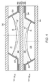
図1〜3に示される液体タンクは実質的につながった容積を有し、ここでは第2の不混和液体22が第1の不混和液体21と第3の不混和液体23とを機械的に結合させている。しかしながら、第2の不混和液体22と1つ以上のさらなる不混和液体とを介して、第1の不混和液体21と第3の不混和液体23とが機械的に結合されるとしてもよいと意図されている。さらに図4に示すように、比較的硬質の隔壁50を第2の不混和液体内に設けてもよい。これにより、液体が分割され、各液体レンズ面13、15を互いに独立して作動させることや、レンズ10の構造を安定させること、レンズ10の組立てを容易にすることなどに役立つ。硬質の隔壁50としては、例えば薄膜のような比較的薄い層を用いてもよいし、例えば透明窓のような比較的厚い部品を用いることもできる。
The liquid tank shown in FIGS. 1-3 has a substantially connected volume, where the second
第1、第2および第3の不混和液体21、22、23の具体的な構造は本発明の範囲を超えたものであるが、これらの液体の不混和性は一般に液体自体の特性に起因するものであることに留意されたい。これらの液体としては、類似した濃度を有する透明な液体を備えることが好ましい。レンズ内で隣り合う液体は一般に異なる屈折率を有するものであり、異なる極性を有するものでもよい。例えば、これに限定されるものではないが、電気応答性を有するオイルを第1および第3の不混和液体として採用し、第2の不混和液体として水性の液体を採用してもよい。米国特許第4,477,158号明細書および米国特許出願公開第2006/0152814号明細書により、レンズ内における不混和液体の使用に関するさらなる教示が提供される。また、液体間に軟性の薄膜を設けることにより、液体の不混和性を高めるように、あるいは単に結果として液体が不混和となるようにすることができると考えられる。さらに、本発明による不混和液体は、レンズ10内に設けられる全ての液体に対して不混和なものである必要はないことに留意されたい。むしろ、隣接する液体に対してのみ不混和なものであればよい。
The specific structure of the first, second and third
図1〜4に示すレンズ面13は、第1の不混和液体21から見て凸状であるということができる。同様に、図1〜4に示すレンズ面15は、第3の不混和液体23から見て凸状であるということができる。これに対し、図5に示すレンズ面13、15は凹状であるといえる。つまり、本発明の実施形態は凸状または凹状のレンズ面を意図している。さらに、図示していないが、本発明の実施形態としてレンズ面13、15の一方を凹状とし、他方を凸状とする形態も考えられる。本発明において実施される特定のレンズ面の形状は、不混和液体21、22、23の特性や、付随するレンズ面接触壁40の特性、および制御電極30、32、34で生成される電位の性質などによって決定される。
The
図1〜5に示すレンズ面は、レンズ10の光伝播軸に平行な、この軸を通る切断面からみると実質的に均一な円周状の面であるが、実際には、図示されたような均一の円弧状の形状とは異なることが多いことに留意されたい。例えば、凸状のレンズ面が楕円形や他の非円形の弧により近いこともあるし、その各断面に平坦なあるいは略平坦な表面部を含むこともある。さらに、平坦なあるいは略平坦なレンズ面をレンズ液体によって形成することもできると考えられる。
The lens surface shown in FIGS. 1 to 5 is a substantially uniform circumferential surface when viewed from a cut surface passing through this axis, which is parallel to the light propagation axis of the
ここまで、電気応答性を有するレンズ液体と各制御電極を使用した例を参照して本発明の構想について示してきた。しかしながら、第1および第2のレンズ液体を、液圧で応答する感圧レンズ液体を含むものとし、各液体タンクへの液体供給を制御することによって凸レンズ面の曲率を制御できるとも意図される。この第1および第2の液体供給は、別々の液体供給としてもよいし、共通の液体供給としてもよい。液体レンズ内における感圧レンズ液体の使用に関しては、米国特許第5,438,486号および同第6,188,526号の各明細書により詳しく教示されている。これらの特許の記述の中で、感圧液体レンズを構成することができる性質を理解するのに有用な部分のみが、参照により本書に組み込まれる。 Up to now, the concept of the present invention has been shown with reference to an example using lens liquid having electrical response and each control electrode. However, it is also intended that the curvature of the convex lens surface can be controlled by controlling the liquid supply to each liquid tank, where the first and second lens liquids include pressure-sensitive lens liquids that respond with liquid pressure. The first and second liquid supplies may be separate liquid supplies or a common liquid supply. The use of pressure sensitive lens liquids in liquid lenses is taught in more detail in US Pat. Nos. 5,438,486 and 6,188,526. In the descriptions of these patents, only the parts useful for understanding the nature of which a pressure sensitive liquid lens can be constructed are incorporated herein by reference.
本発明による液体レンズが光学系内で伝播する光を導くように設定される場合には、例えばレーザチップのような入力光学装置から例えばSHG結晶のような出力光学装置へと導かれる光を実質的にコリメートするように構成されたコリメート光学部品を、そのレンズにさらに備えてもよいと考えられる。さらに、コリメート光学部品を導入することにより、そうしなければ可変焦点レンズに降りかかるであろう光パワー要求を軽減することができる。具体的には、コリメート光学部品を主に系の1次光学部品として機能するように設定する一方、可変焦点レンズを主に2次補正系として機能するように設計することができる。 When the liquid lens according to the present invention is set to guide the light propagating in the optical system, the light guided from the input optical device such as a laser chip to the output optical device such as an SHG crystal is substantially reduced. It is contemplated that the lens may further include a collimating optical component configured to collimate in a mechanical manner. Furthermore, the introduction of collimating optics can reduce the optical power requirements that would otherwise fall on the variable focus lens. Specifically, it is possible to design the collimating optical component so as to mainly function as the primary optical component of the system while the variable focus lens mainly functions as the secondary correction system.
本発明による可変焦点レンズは、小規模および大規模のオプトメカニカルパッケージにおいて特に有用であると考えられる。なぜなら、このようなオプトメカニカルパッケージにおいて、光学部品の機械的調整を適切に行うことを保証するのは一般的に困難だからである。例えば、レーザチップと第2高調波発生(SHG)結晶の光導波路型光波長変換装置とを有する半導体レーザに関して、光学部品をサブミクロンオーダーで調整することがしばしば必要であることを本発明の発明者は認識していた。実例として、限定されるものではないが、本発明が意図するオプトメカニカルパッケージとして付け加えることができるものに、第2高調波発生レーザパッケージと、励起型レーザパッケージと、シングルまたはマルチモードの光信号が光導波路や、光ファイバや、光学結晶や、あるいは種々の組合せの能動または受動光学部品の間を伝送する他の光パッケージとが含まれることに留意されたい。 The variable focus lens according to the invention is believed to be particularly useful in small and large optomechanical packages. This is because, in such an opto-mechanical package, it is generally difficult to ensure that the optical components are properly mechanically adjusted. For example, for a semiconductor laser having a laser chip and a second harmonic generation (SHG) crystal optical waveguide optical wavelength converter, it is often necessary to adjust the optical components on the submicron order. Was aware. By way of illustration and not limitation, a second harmonic generation laser package, a pumped laser package, and a single or multimode optical signal can be added as an optomechanical package intended by the present invention. Note that optical waveguides, optical fibers, optical crystals, or other optical packages that transmit between various combinations of active or passive optical components are included.
本発明を記述し定義する上で、「実質的に」という用語は、ここでは、任意の定量比較、定量値、定量的測定、あるいは他の定量的表記にもともと含まれている不明確さの固有の程度を表すために使用されていることに留意されたい。「実質的に」という用語はまた、ある定量的表記が、本発明の主題の基本的な機能を変更しないものであれば記述したものから異なってよい程度を表すためにここで使用されている。「実質的に」という用語はさらに、ある定量的表記が、本発明の主題の記載された機能を生じることとなる、記述したものと異なっているに違いない最低限の程度を表すためにここで使用されている。 In describing and defining the present invention, the term “substantially” is used herein to refer to any ambiguity inherent in any quantitative comparison, quantitative value, quantitative measurement, or other quantitative notation. Note that it is used to represent a unique degree. The term “substantially” is also used herein to indicate the extent to which a quantitative notation may differ from what has been described so long as it does not alter the basic function of the inventive subject matter. . The term “substantially” is further used here to represent the minimum degree that certain quantitative notations must be different from those described that will result in the described function of the subject matter of the present invention. Used in.
本発明に関して詳細に、そしてその特定の実施の形態を参照して記述したことにより、添付の特許請求の範囲で定義される本発明の範囲から外れることなく、種々の改変や変形が可能であることは明らかであろう。より詳しくは、本発明における態様の中には好ましい、あるいは特に有利であるとここで認められるものがあるかもしれないが、本発明はこれらの態様に必ずしも限定されるものではないと意図される。 Various details and modifications can be made without departing from the scope of the present invention as defined in the appended claims by having described the invention in detail and with reference to specific embodiments thereof. It will be clear. More particularly, some of the embodiments in the present invention may be recognized herein as being preferred or particularly advantageous, but it is intended that the present invention is not necessarily limited to these embodiments. .
10 液体レンズ
12 第1の液体レンズ部品
13 第1のレンズ面
14 第2の液体レンズ部品
15 第2のレンズ面
16 第3の液体レンズ部品
17 第3のレンズ面
20 液体タンク
21 第1の不混和液体
22 第2の不混和液体
23 第3の不混和液体
24 入力窓
26 出力窓
30、32、34 制御電極
DESCRIPTION OF
Claims (10)
前記第1の液体レンズ部品が、前記レンズの液体タンク内に収容された第1および第2の液体の界面に沿って形成される第1のレンズ面を備え、
前記第1および第2の液体が互いに不混和であり、
前記第2の液体レンズ部品が、前記液体タンク内に収容された第2および第3の液体の界面に沿って形成される第2のレンズ面を備え、
前記第2および第3の液体が互いに不混和であり、
前記第1の液体が、前記第2の液体を介して前記第3の液体と機械的に結合し、
前記第2の液体の屈折率が、前記第1および第3の液体の屈折率と実質的に異なるものであり、
前記液体レンズは、光信号が、前記第1および第2のレンズ部品の前記第1および第2のレンズ面を通って延在する光伝播軸に沿って前記レンズの入力側から該レンズの出力側へと伝播することができるように構成され、かつ、
該液体レンズが、前記第1および第2のレンズ面の少なくとも一方を変化させることができるように構成されることを特徴とする液体レンズ。 A liquid lens comprising first and second liquid lens components,
The first liquid lens component comprises a first lens surface formed along an interface between the first and second liquids housed in a liquid tank of the lens;
The first and second liquids are immiscible with each other;
The second liquid lens component includes a second lens surface formed along an interface between the second and third liquids housed in the liquid tank;
The second and third liquids are immiscible with each other;
The first liquid is mechanically coupled to the third liquid via the second liquid;
The refractive index of the second liquid is substantially different from the refractive index of the first and third liquids;
The liquid lens has an optical signal from the input side of the lens along an optical propagation axis extending through the first and second lens surfaces of the first and second lens components. Configured to be able to propagate to the side, and
The liquid lens is configured so that at least one of the first lens surface and the second lens surface can be changed.
前記第3の液体レンズ部品の前記第1および第2の液体が互いに不混和であり、
前記第1および第2のレンズ面が、前記光伝播軸zに直交する方向xに沿って互いにずらされた位置にあり、かつ、
前記第1および第2のレンズ面の一方もしくは両方が、前記第3のレンズ面に対して、前記方向xと前記光伝播軸zとに直交する方向yに沿って互いにずらされた位置にあることを特徴とする請求項1記載の液体レンズ。 The liquid lens further includes a third liquid lens component having a third lens surface along an interface between the first and second liquids housed in a liquid tank further provided on the lens;
The first and second liquids of the third liquid lens component are immiscible with each other;
The first and second lens surfaces are offset from each other along a direction x orthogonal to the light propagation axis z; and
One or both of the first and second lens surfaces are shifted from each other along a direction y orthogonal to the direction x and the light propagation axis z with respect to the third lens surface. The liquid lens according to claim 1.
該液体レンズが、前記伝播光に広範囲なビーム操舵効果を生み出す手法により、または前記液体レンズの焦点距離を変化させる手法により、あるいは両手法により、前記レーザチップの出力から前記光波長変換装置の入力へと伝播光を導くように構成されることを特徴とする請求項4記載の光学系。 The optical system includes a semiconductor laser including a laser chip, an optical wavelength conversion device, and the liquid lens, and
The liquid lens is input to the optical wavelength converter from the output of the laser chip by a method that generates a wide beam steering effect on the propagating light, a method that changes a focal length of the liquid lens, or both methods. The optical system according to claim 4, wherein the optical system is configured to guide the propagating light to the side.
前記レンズが、少なくとも2つのさらに異なる電界を独立に生成するように構成された第2組の制御電極を備え、各電界が前記第2のレンズ面の少なくとも1つの態様を変えることが可能なものであることを特徴とする請求項1記載の液体レンズ。 The lens comprises a first set of control electrodes configured to independently generate at least two different electric fields, each electric field being capable of changing at least one aspect of the first lens surface. Yes, and
The lens comprises a second set of control electrodes configured to independently generate at least two further different electric fields, each electric field being capable of changing at least one aspect of the second lens surface The liquid lens according to claim 1, wherein:
Applications Claiming Priority (2)
| Application Number | Priority Date | Filing Date | Title |
|---|---|---|---|
| US11/593,767 US7324287B1 (en) | 2006-11-07 | 2006-11-07 | Multi-fluid lenses and optical devices incorporating the same |
| PCT/US2007/023345 WO2008057525A1 (en) | 2006-11-07 | 2007-11-06 | Multi-fluid lenses and optical devices incorporating the same |
Publications (1)
| Publication Number | Publication Date |
|---|---|
| JP2010509640A true JP2010509640A (en) | 2010-03-25 |
Family
ID=38973933
Family Applications (1)
| Application Number | Title | Priority Date | Filing Date |
|---|---|---|---|
| JP2009536271A Pending JP2010509640A (en) | 2006-11-07 | 2007-11-06 | Compound liquid lens and optical device incorporating the same |
Country Status (5)
| Country | Link |
|---|---|
| US (1) | US7324287B1 (en) |
| JP (1) | JP2010509640A (en) |
| CN (1) | CN101558332B (en) |
| TW (1) | TW200844483A (en) |
| WO (1) | WO2008057525A1 (en) |
Cited By (6)
| Publication number | Priority date | Publication date | Assignee | Title |
|---|---|---|---|---|
| WO2015005591A1 (en) * | 2013-07-11 | 2015-01-15 | 포항공과대학교 산학협력단 | Electrohydrodynamic liquid lens |
| JP2018533747A (en) * | 2015-11-09 | 2018-11-15 | ビョルン・ハブリヒBjorn HABRICH | Method and device for determining the spatial position of an object by interferometric measurement |
| KR20200074751A (en) * | 2018-12-17 | 2020-06-25 | 엘지이노텍 주식회사 | Lens module and camera module including the module |
| WO2020130508A1 (en) * | 2018-12-17 | 2020-06-25 | 엘지이노텍(주) | Lens module and camera module including same |
| WO2020153786A1 (en) * | 2019-01-25 | 2020-07-30 | 엘지이노텍(주) | Liquid lens |
| KR20200106254A (en) * | 2019-03-04 | 2020-09-14 | 엘지이노텍 주식회사 | Liquid lens module |
Families Citing this family (51)
| Publication number | Priority date | Publication date | Assignee | Title |
|---|---|---|---|---|
| AU2008331643B2 (en) * | 2007-12-04 | 2014-04-10 | Blackeye Optics, Llc | Image stabilization system using one, or more, liquid lens |
| JP2011509415A (en) | 2007-12-04 | 2011-03-24 | ブラックアイ オプティクス,エルエルシー | Telephoto zoom lens with liquid lens in fixed group |
| US7898740B2 (en) | 2008-04-09 | 2011-03-01 | Seereal Technologies S.A. | Tunable optical array device comprising liquid cells |
| US9675443B2 (en) | 2009-09-10 | 2017-06-13 | Johnson & Johnson Vision Care, Inc. | Energized ophthalmic lens including stacked integrated components |
| CN102170938B (en) * | 2008-09-30 | 2015-01-14 | 皇家飞利浦电子股份有限公司 | System and method for ultrasound therapy treatment |
| US8087778B2 (en) | 2009-02-13 | 2012-01-03 | Adlens Beacon, Inc. | Variable focus liquid filled lens mechanism |
| US20100208194A1 (en) * | 2009-02-13 | 2010-08-19 | Amitava Gupta | Variable focus liquid filled lens apparatus |
| US8414121B2 (en) * | 2009-10-13 | 2013-04-09 | Adlens Beacon, Inc. | Non-round fluid filled lens optic |
| US8817381B2 (en) | 2009-10-13 | 2014-08-26 | Adlens Beacon, Inc. | Full field membrane design for non-round liquid lens assemblies |
| US8136942B2 (en) | 2009-10-14 | 2012-03-20 | Adlens Beacon, Inc. | Aspheric fluid filled lens optic |
| US8353593B2 (en) | 2009-10-15 | 2013-01-15 | Adlens Beacon, Inc. | Hinge mechanism for a fluid filled lens assembly |
| MX2012004396A (en) | 2009-10-15 | 2012-08-17 | Adlens Beacon Inc | Fluid filled lenses and mechanisms of inflation thereof. |
| US8596781B2 (en) * | 2009-10-15 | 2013-12-03 | Adlens Beacon, Inc. | Fluid filled lens reservoir system and manufacturing method of the reservoir system |
| TWI422882B (en) * | 2009-12-08 | 2014-01-11 | Univ Nat Chiao Tung | A fluidic optical waveguide and a formation method of the same |
| JP5590901B2 (en) * | 2010-02-03 | 2014-09-17 | キヤノン株式会社 | Refractive power variable element |
| US9036264B2 (en) | 2010-08-12 | 2015-05-19 | Adlens Beacon, Inc. | Fluid-filled lenses and their ophthalmic applications |
| US20120092774A1 (en) * | 2010-09-27 | 2012-04-19 | Pugh Randall B | Lens with multi-segmented linear meniscus wall |
| DE102010047457A1 (en) * | 2010-10-06 | 2012-04-12 | Albert-Ludwigs-Universität Freiburg | Numerical method for modeling, optimization, regulation and/or approximation of e.g. optical wavefront of mirror of optical system, involves modeling physical mechanical parameter of optical component |
| JP6212791B2 (en) | 2010-10-11 | 2017-10-18 | アドレンズ ビーコン インコーポレイテッド | Ambient piezoelectric reservoir in the lens |
| USD665009S1 (en) | 2010-10-14 | 2012-08-07 | Adlens Beacon, Inc. | Spectacles frame |
| CA3074632A1 (en) | 2010-11-10 | 2012-05-18 | Adlens Beacon, Inc. | Fluid-filled lenses and actuation systems thereof |
| US9110310B2 (en) | 2011-03-18 | 2015-08-18 | Johnson & Johnson Vision Care, Inc. | Multiple energization elements in stacked integrated component devices |
| US10451897B2 (en) | 2011-03-18 | 2019-10-22 | Johnson & Johnson Vision Care, Inc. | Components with multiple energization elements for biomedical devices |
| US9698129B2 (en) | 2011-03-18 | 2017-07-04 | Johnson & Johnson Vision Care, Inc. | Stacked integrated component devices with energization |
| US8867141B2 (en) * | 2011-03-18 | 2014-10-21 | Johnson & Johnson Vision Care, Inc. | Lens with multi-concave meniscus wall |
| US9233513B2 (en) | 2011-03-18 | 2016-01-12 | Johnson & Johnson Vision Care, Inc. | Apparatus for manufacturing stacked integrated component media inserts for ophthalmic devices |
| US9804418B2 (en) | 2011-03-21 | 2017-10-31 | Johnson & Johnson Vision Care, Inc. | Methods and apparatus for functional insert with power layer |
| US8857983B2 (en) | 2012-01-26 | 2014-10-14 | Johnson & Johnson Vision Care, Inc. | Ophthalmic lens assembly having an integrated antenna structure |
| WO2013126042A2 (en) * | 2012-02-21 | 2013-08-29 | E-Vision Smart Optics, Inc. | Systems, devices, and/or methods for managing aberrations |
| US9535264B2 (en) | 2012-07-13 | 2017-01-03 | Adlens Beacon, Inc. | Fluid lenses, lens blanks, and methods of manufacturing the same |
| US20140135917A1 (en) * | 2012-11-13 | 2014-05-15 | Vision Solutions Technologies, Inc. | Multi-focus intraocular prosthesis |
| FR3015699B1 (en) * | 2013-12-20 | 2016-02-05 | Wavelens | OPTICAL DEVICE FOR STABILIZING IMAGES |
| CN103792665A (en) * | 2014-01-26 | 2014-05-14 | 浙江工业大学 | Beam shaping device based on microfluidic optical technology |
| US9383593B2 (en) | 2014-08-21 | 2016-07-05 | Johnson & Johnson Vision Care, Inc. | Methods to form biocompatible energization elements for biomedical devices comprising laminates and placed separators |
| US10627651B2 (en) | 2014-08-21 | 2020-04-21 | Johnson & Johnson Vision Care, Inc. | Methods and apparatus to form biocompatible energization primary elements for biomedical devices with electroless sealing layers |
| US9941547B2 (en) | 2014-08-21 | 2018-04-10 | Johnson & Johnson Vision Care, Inc. | Biomedical energization elements with polymer electrolytes and cavity structures |
| US9793536B2 (en) | 2014-08-21 | 2017-10-17 | Johnson & Johnson Vision Care, Inc. | Pellet form cathode for use in a biocompatible battery |
| US10361404B2 (en) | 2014-08-21 | 2019-07-23 | Johnson & Johnson Vision Care, Inc. | Anodes for use in biocompatible energization elements |
| US9599842B2 (en) | 2014-08-21 | 2017-03-21 | Johnson & Johnson Vision Care, Inc. | Device and methods for sealing and encapsulation for biocompatible energization elements |
| US10361405B2 (en) | 2014-08-21 | 2019-07-23 | Johnson & Johnson Vision Care, Inc. | Biomedical energization elements with polymer electrolytes |
| US9715130B2 (en) | 2014-08-21 | 2017-07-25 | Johnson & Johnson Vision Care, Inc. | Methods and apparatus to form separators for biocompatible energization elements for biomedical devices |
| US10381687B2 (en) | 2014-08-21 | 2019-08-13 | Johnson & Johnson Vision Care, Inc. | Methods of forming biocompatible rechargable energization elements for biomedical devices |
| WO2016077252A1 (en) * | 2014-11-10 | 2016-05-19 | Didomenico Leo D | Wide-angle, broad-band, polarization independent beam steering and concentration of wave energy utilizing electronically controlled soft matter |
| US10345620B2 (en) | 2016-02-18 | 2019-07-09 | Johnson & Johnson Vision Care, Inc. | Methods and apparatus to form biocompatible energization elements incorporating fuel cells for biomedical devices |
| US10598919B2 (en) * | 2016-03-04 | 2020-03-24 | The Regents Of The University Of Colorado | Electrowetting-actuated optical shutters |
| US11402623B2 (en) | 2017-08-02 | 2022-08-02 | Corning Incorporated | Flexible subtrate and circuit for liquid lens system |
| TWI774854B (en) * | 2017-10-13 | 2022-08-21 | 美商康寧公司 | Methods and apparatus for pressing glass or glass-ceramic preforms to form shaped plates, methods for manufacturing liquid lenses, and liquid lenses |
| US10422989B2 (en) * | 2018-02-06 | 2019-09-24 | Microsoft Technology Licensing, Llc | Optical systems including a single actuator and multiple fluid-filled optical lenses for near-eye-display devices |
| US20210088697A1 (en) * | 2018-03-16 | 2021-03-25 | Lg Electronics Inc. | Liquid iris, optical device comprising same, and mobile terminal |
| US10826609B2 (en) | 2018-06-20 | 2020-11-03 | Massachusetts Institute Of Technology | Liquid-lens based optical steering system for free-space laser communication |
| KR20210039147A (en) * | 2019-10-01 | 2021-04-09 | 엘지이노텍 주식회사 | Liquid lens and liquid lens assembly |
Citations (5)
| Publication number | Priority date | Publication date | Assignee | Title |
|---|---|---|---|---|
| WO2004038480A1 (en) * | 2002-10-25 | 2004-05-06 | Koninklijke Philips Electronics N.V. | Zoom lens |
| WO2004051323A1 (en) * | 2002-12-03 | 2004-06-17 | Koninklijke Philips Electronics N.V. | Apparatus for forming variable fluid meniscus configurations |
| WO2004077125A2 (en) * | 2003-02-25 | 2004-09-10 | Koninklijke Philips Electronics N.V. | Improvements in and relating to fluid filled devices |
| WO2007063464A1 (en) * | 2005-11-30 | 2007-06-07 | Koninklijke Philips Electronics N.V. | Optical scanning device. |
| JP2008542890A (en) * | 2005-06-02 | 2008-11-27 | ブンデスドルケライ ゲーエムベーハー | Method for accessing an electronic device by means of a data terminal |
Family Cites Families (15)
| Publication number | Priority date | Publication date | Assignee | Title |
|---|---|---|---|---|
| US4477158A (en) | 1981-10-15 | 1984-10-16 | Pollock Stephen C | Lens system for variable refraction |
| US5438486A (en) | 1992-07-20 | 1995-08-01 | Mcnair; Edward P. | Headlights with variably shaped optical elements |
| US5491583A (en) * | 1994-06-17 | 1996-02-13 | Lockheed Missiles & Space Company, Inc. | Infrared lens systems |
| DE59701885D1 (en) * | 1996-03-26 | 2000-07-20 | Mannesmann Ag | OPTOELECTRONIC IMAGE SYSTEM FOR INDUSTRIAL APPLICATIONS |
| FR2769375B1 (en) | 1997-10-08 | 2001-01-19 | Univ Joseph Fourier | VARIABLE FOCAL LENS |
| US20050002113A1 (en) | 1997-10-08 | 2005-01-06 | Varioptic | Drop centering device |
| US6445509B1 (en) * | 1999-08-16 | 2002-09-03 | Ray Marvin Alden | Variable fresnel type structures and process |
| JP4078575B2 (en) | 1998-06-26 | 2008-04-23 | 株式会社デンソー | Variable focus lens device |
| US6538823B2 (en) | 2001-06-19 | 2003-03-25 | Lucent Technologies Inc. | Tunable liquid microlens |
| CN1325944C (en) * | 2002-12-03 | 2007-07-11 | 皇家飞利浦电子股份有限公司 | Apparatus for forming variable fluid meniscus configurations |
| JP4220543B2 (en) | 2003-03-17 | 2009-02-04 | ノキア コーポレイション | Method and apparatus for lateral adjustment of an image |
| US6778328B1 (en) | 2003-03-28 | 2004-08-17 | Lucent Technologies Inc. | Tunable field of view liquid microlens |
| WO2005096289A1 (en) * | 2004-03-31 | 2005-10-13 | Koninklijke Philips Electronics N.V. | Optical scanning device |
| FR2880135B1 (en) | 2004-12-23 | 2007-03-16 | Varioptic Sa | VARIABLE FOCAL LENS WITH WIDE RANGE OF VARIATION |
| DE102005005933A1 (en) * | 2005-02-09 | 2006-08-17 | Carl Zeiss Meditec Ag | Variable optics |
-
2006
- 2006-11-07 US US11/593,767 patent/US7324287B1/en not_active Expired - Fee Related
-
2007
- 2007-11-06 JP JP2009536271A patent/JP2010509640A/en active Pending
- 2007-11-06 CN CN2007800457439A patent/CN101558332B/en not_active Expired - Fee Related
- 2007-11-06 WO PCT/US2007/023345 patent/WO2008057525A1/en active Application Filing
- 2007-11-07 TW TW096142165A patent/TW200844483A/en unknown
Patent Citations (9)
| Publication number | Priority date | Publication date | Assignee | Title |
|---|---|---|---|---|
| WO2004038480A1 (en) * | 2002-10-25 | 2004-05-06 | Koninklijke Philips Electronics N.V. | Zoom lens |
| JP2006504132A (en) * | 2002-10-25 | 2006-02-02 | コーニンクレッカ フィリップス エレクトロニクス エヌ ヴィ | Zoom lens |
| WO2004051323A1 (en) * | 2002-12-03 | 2004-06-17 | Koninklijke Philips Electronics N.V. | Apparatus for forming variable fluid meniscus configurations |
| JP2006509263A (en) * | 2002-12-03 | 2006-03-16 | コーニンクレッカ フィリップス エレクトロニクス エヌ ヴィ | Apparatus for forming variable fluid meniscus structure |
| WO2004077125A2 (en) * | 2003-02-25 | 2004-09-10 | Koninklijke Philips Electronics N.V. | Improvements in and relating to fluid filled devices |
| JP2007528008A (en) * | 2003-02-25 | 2007-10-04 | コーニンクレッカ フィリップス エレクトロニクス エヌ ヴィ | Improvements in and relating to fluid-filled devices |
| JP2008542890A (en) * | 2005-06-02 | 2008-11-27 | ブンデスドルケライ ゲーエムベーハー | Method for accessing an electronic device by means of a data terminal |
| WO2007063464A1 (en) * | 2005-11-30 | 2007-06-07 | Koninklijke Philips Electronics N.V. | Optical scanning device. |
| JP2009517712A (en) * | 2005-11-30 | 2009-04-30 | コーニンクレッカ フィリップス エレクトロニクス エヌ ヴィ | Optical scanning device |
Cited By (9)
| Publication number | Priority date | Publication date | Assignee | Title |
|---|---|---|---|---|
| WO2015005591A1 (en) * | 2013-07-11 | 2015-01-15 | 포항공과대학교 산학협력단 | Electrohydrodynamic liquid lens |
| JP2018533747A (en) * | 2015-11-09 | 2018-11-15 | ビョルン・ハブリヒBjorn HABRICH | Method and device for determining the spatial position of an object by interferometric measurement |
| KR20200074751A (en) * | 2018-12-17 | 2020-06-25 | 엘지이노텍 주식회사 | Lens module and camera module including the module |
| WO2020130508A1 (en) * | 2018-12-17 | 2020-06-25 | 엘지이노텍(주) | Lens module and camera module including same |
| US12061406B2 (en) | 2018-12-17 | 2024-08-13 | Lg Innotek Co., Ltd. | Lens module and camera module including same |
| KR102779328B1 (en) * | 2018-12-17 | 2025-03-11 | 엘지이노텍 주식회사 | Lens module and camera module including the module |
| WO2020153786A1 (en) * | 2019-01-25 | 2020-07-30 | 엘지이노텍(주) | Liquid lens |
| KR20200106254A (en) * | 2019-03-04 | 2020-09-14 | 엘지이노텍 주식회사 | Liquid lens module |
| KR102726465B1 (en) * | 2019-03-04 | 2024-11-06 | 엘지이노텍 주식회사 | Liquid lens module |
Also Published As
| Publication number | Publication date |
|---|---|
| CN101558332B (en) | 2011-03-09 |
| TW200844483A (en) | 2008-11-16 |
| US7324287B1 (en) | 2008-01-29 |
| WO2008057525A1 (en) | 2008-05-15 |
| CN101558332A (en) | 2009-10-14 |
Similar Documents
| Publication | Publication Date | Title |
|---|---|---|
| JP2010509640A (en) | Compound liquid lens and optical device incorporating the same | |
| US11075500B2 (en) | Optical device having a substrate and a laser unit that emits light into the substrate | |
| EP3182179B1 (en) | Integrally formed coupling module | |
| EP2626731B1 (en) | An optical coupling arrangement | |
| KR20140135014A (en) | optical modulator and optical module used the same | |
| JP2013182241A (en) | Optical receptacle and optical module including the same | |
| WO2019159345A1 (en) | Semiconductor optical integrated device | |
| US20140071540A1 (en) | Optical splitting device | |
| CN101930096B (en) | Optical subassembly for coupling light into an optical waveguide | |
| JP2010503891A (en) | Semiconductor laser | |
| CN111029906B (en) | Correcting system of laser, light source system and projection device | |
| US20110141393A1 (en) | Optical devices | |
| KR101824873B1 (en) | Optical microphone system using planar lightwave circuit | |
| US20130208750A1 (en) | Semiconductor laser diode having waveguide lens | |
| US20230110382A1 (en) | Multi-Mode Devices for Multiplexing and De-Multiplexing | |
| US9158077B2 (en) | Waveguide lens including planar waveguide and media grating | |
| JP2007033859A (en) | Optical transmission line | |
| US20140185985A1 (en) | Waveguide lens for coupling laser light source and optical element | |
| JP5742331B2 (en) | Laser light scanner | |
| JP6025116B2 (en) | Semiconductor laser device | |
| CN110174770B (en) | A device and method for generating Bessel beams with multi-segment stable transmission on an axis | |
| CN209640611U (en) | A device for generating Bessel beams with multi-segment stable transmission on the axis | |
| JP6028509B2 (en) | Semiconductor laser device | |
| US20140169726A1 (en) | Waveguide lens with modulating electrode and ground electrodes | |
| WO2023135649A1 (en) | Grating coupler |
Legal Events
| Date | Code | Title | Description |
|---|---|---|---|
| A621 | Written request for application examination |
Free format text: JAPANESE INTERMEDIATE CODE: A621 Effective date: 20100826 |
|
| A521 | Request for written amendment filed |
Free format text: JAPANESE INTERMEDIATE CODE: A523 Effective date: 20110405 |
|
| A977 | Report on retrieval |
Free format text: JAPANESE INTERMEDIATE CODE: A971007 Effective date: 20120626 |
|
| A131 | Notification of reasons for refusal |
Free format text: JAPANESE INTERMEDIATE CODE: A131 Effective date: 20120703 |
|
| A02 | Decision of refusal |
Free format text: JAPANESE INTERMEDIATE CODE: A02 Effective date: 20121204 |