JP2009524518A - Apparatus for absorbing gas or vapor into liquid and method for reintroducing vapor or gas into a liquid from which vapor or gas is generated - Google Patents
Apparatus for absorbing gas or vapor into liquid and method for reintroducing vapor or gas into a liquid from which vapor or gas is generated Download PDFInfo
- Publication number
- JP2009524518A JP2009524518A JP2008552258A JP2008552258A JP2009524518A JP 2009524518 A JP2009524518 A JP 2009524518A JP 2008552258 A JP2008552258 A JP 2008552258A JP 2008552258 A JP2008552258 A JP 2008552258A JP 2009524518 A JP2009524518 A JP 2009524518A
- Authority
- JP
- Japan
- Prior art keywords
- liquid
- gas
- ejector
- tank
- vapor
- Prior art date
- Legal status (The legal status is an assumption and is not a legal conclusion. Google has not performed a legal analysis and makes no representation as to the accuracy of the status listed.)
- Granted
Links
- 239000007788 liquid Substances 0.000 title claims abstract description 68
- 238000000034 method Methods 0.000 title claims description 13
- 230000002093 peripheral effect Effects 0.000 claims abstract 3
- 239000004215 Carbon black (E152) Substances 0.000 claims description 4
- 229930195733 hydrocarbon Natural products 0.000 claims description 4
- 150000002430 hydrocarbons Chemical class 0.000 claims description 4
- 239000012530 fluid Substances 0.000 claims description 2
- 239000007789 gas Substances 0.000 description 46
- 238000010521 absorption reaction Methods 0.000 description 4
- 239000003208 petroleum Substances 0.000 description 3
- 230000000694 effects Effects 0.000 description 2
- 230000008020 evaporation Effects 0.000 description 2
- 238000001704 evaporation Methods 0.000 description 2
- 238000009434 installation Methods 0.000 description 2
- 238000004140 cleaning Methods 0.000 description 1
- 230000007423 decrease Effects 0.000 description 1
- 230000001419 dependent effect Effects 0.000 description 1
- 238000009826 distribution Methods 0.000 description 1
- 239000002360 explosive Substances 0.000 description 1
- 239000007791 liquid phase Substances 0.000 description 1
- 238000012423 maintenance Methods 0.000 description 1
- 238000012986 modification Methods 0.000 description 1
- 230000004048 modification Effects 0.000 description 1
- 239000002244 precipitate Substances 0.000 description 1
- 231100000331 toxic Toxicity 0.000 description 1
- 230000002588 toxic effect Effects 0.000 description 1
- 238000009827 uniform distribution Methods 0.000 description 1
- 239000012855 volatile organic compound Substances 0.000 description 1
Images


Classifications
-
- F—MECHANICAL ENGINEERING; LIGHTING; HEATING; WEAPONS; BLASTING
- F17—STORING OR DISTRIBUTING GASES OR LIQUIDS
- F17C—VESSELS FOR CONTAINING OR STORING COMPRESSED, LIQUEFIED OR SOLIDIFIED GASES; FIXED-CAPACITY GAS-HOLDERS; FILLING VESSELS WITH, OR DISCHARGING FROM VESSELS, COMPRESSED, LIQUEFIED, OR SOLIDIFIED GASES
- F17C13/00—Details of vessels or of the filling or discharging of vessels
-
- B—PERFORMING OPERATIONS; TRANSPORTING
- B01—PHYSICAL OR CHEMICAL PROCESSES OR APPARATUS IN GENERAL
- B01F—MIXING, e.g. DISSOLVING, EMULSIFYING OR DISPERSING
- B01F23/00—Mixing according to the phases to be mixed, e.g. dispersing or emulsifying
- B01F23/20—Mixing gases with liquids
- B01F23/23—Mixing gases with liquids by introducing gases into liquid media, e.g. for producing aerated liquids
- B01F23/232—Mixing gases with liquids by introducing gases into liquid media, e.g. for producing aerated liquids using flow-mixing means for introducing the gases, e.g. baffles
- B01F23/2323—Mixing gases with liquids by introducing gases into liquid media, e.g. for producing aerated liquids using flow-mixing means for introducing the gases, e.g. baffles by circulating the flow in guiding constructions or conduits
-
- B—PERFORMING OPERATIONS; TRANSPORTING
- B01—PHYSICAL OR CHEMICAL PROCESSES OR APPARATUS IN GENERAL
- B01F—MIXING, e.g. DISSOLVING, EMULSIFYING OR DISPERSING
- B01F25/00—Flow mixers; Mixers for falling materials, e.g. solid particles
- B01F25/30—Injector mixers
- B01F25/31—Injector mixers in conduits or tubes through which the main component flows
- B01F25/314—Injector mixers in conduits or tubes through which the main component flows wherein additional components are introduced at the circumference of the conduit
-
- F—MECHANICAL ENGINEERING; LIGHTING; HEATING; WEAPONS; BLASTING
- F17—STORING OR DISTRIBUTING GASES OR LIQUIDS
- F17C—VESSELS FOR CONTAINING OR STORING COMPRESSED, LIQUEFIED OR SOLIDIFIED GASES; FIXED-CAPACITY GAS-HOLDERS; FILLING VESSELS WITH, OR DISCHARGING FROM VESSELS, COMPRESSED, LIQUEFIED, OR SOLIDIFIED GASES
- F17C11/00—Use of gas-solvents or gas-sorbents in vessels
-
- B—PERFORMING OPERATIONS; TRANSPORTING
- B01—PHYSICAL OR CHEMICAL PROCESSES OR APPARATUS IN GENERAL
- B01F—MIXING, e.g. DISSOLVING, EMULSIFYING OR DISPERSING
- B01F2101/00—Mixing characterised by the nature of the mixed materials or by the application field
- B01F2101/503—Mixing fuel or propellant and water or gas, e.g. air, or other fluids, e.g. liquid additives to obtain fluid fuel
-
- F—MECHANICAL ENGINEERING; LIGHTING; HEATING; WEAPONS; BLASTING
- F17—STORING OR DISTRIBUTING GASES OR LIQUIDS
- F17C—VESSELS FOR CONTAINING OR STORING COMPRESSED, LIQUEFIED OR SOLIDIFIED GASES; FIXED-CAPACITY GAS-HOLDERS; FILLING VESSELS WITH, OR DISCHARGING FROM VESSELS, COMPRESSED, LIQUEFIED, OR SOLIDIFIED GASES
- F17C2221/00—Handled fluid, in particular type of fluid
- F17C2221/03—Mixtures
- F17C2221/032—Hydrocarbons
-
- F—MECHANICAL ENGINEERING; LIGHTING; HEATING; WEAPONS; BLASTING
- F17—STORING OR DISTRIBUTING GASES OR LIQUIDS
- F17C—VESSELS FOR CONTAINING OR STORING COMPRESSED, LIQUEFIED OR SOLIDIFIED GASES; FIXED-CAPACITY GAS-HOLDERS; FILLING VESSELS WITH, OR DISCHARGING FROM VESSELS, COMPRESSED, LIQUEFIED, OR SOLIDIFIED GASES
- F17C2223/00—Handled fluid before transfer, i.e. state of fluid when stored in the vessel or before transfer from the vessel
- F17C2223/01—Handled fluid before transfer, i.e. state of fluid when stored in the vessel or before transfer from the vessel characterised by the phase
- F17C2223/0146—Two-phase
- F17C2223/0153—Liquefied gas, e.g. LPG, GPL
-
- F—MECHANICAL ENGINEERING; LIGHTING; HEATING; WEAPONS; BLASTING
- F17—STORING OR DISTRIBUTING GASES OR LIQUIDS
- F17C—VESSELS FOR CONTAINING OR STORING COMPRESSED, LIQUEFIED OR SOLIDIFIED GASES; FIXED-CAPACITY GAS-HOLDERS; FILLING VESSELS WITH, OR DISCHARGING FROM VESSELS, COMPRESSED, LIQUEFIED, OR SOLIDIFIED GASES
- F17C2265/00—Effects achieved by gas storage or gas handling
- F17C2265/02—Mixing fluids
- F17C2265/022—Mixing fluids identical fluid
-
- F—MECHANICAL ENGINEERING; LIGHTING; HEATING; WEAPONS; BLASTING
- F17—STORING OR DISTRIBUTING GASES OR LIQUIDS
- F17C—VESSELS FOR CONTAINING OR STORING COMPRESSED, LIQUEFIED OR SOLIDIFIED GASES; FIXED-CAPACITY GAS-HOLDERS; FILLING VESSELS WITH, OR DISCHARGING FROM VESSELS, COMPRESSED, LIQUEFIED, OR SOLIDIFIED GASES
- F17C2265/00—Effects achieved by gas storage or gas handling
- F17C2265/03—Treating the boil-off
- F17C2265/032—Treating the boil-off by recovery
- F17C2265/037—Treating the boil-off by recovery with pressurising
-
- F—MECHANICAL ENGINEERING; LIGHTING; HEATING; WEAPONS; BLASTING
- F17—STORING OR DISTRIBUTING GASES OR LIQUIDS
- F17C—VESSELS FOR CONTAINING OR STORING COMPRESSED, LIQUEFIED OR SOLIDIFIED GASES; FIXED-CAPACITY GAS-HOLDERS; FILLING VESSELS WITH, OR DISCHARGING FROM VESSELS, COMPRESSED, LIQUEFIED, OR SOLIDIFIED GASES
- F17C2270/00—Applications
- F17C2270/01—Applications for fluid transport or storage
- F17C2270/0102—Applications for fluid transport or storage on or in the water
- F17C2270/0105—Ships
Landscapes
- Chemical & Material Sciences (AREA)
- Chemical Kinetics & Catalysis (AREA)
- Engineering & Computer Science (AREA)
- Mechanical Engineering (AREA)
- General Engineering & Computer Science (AREA)
- Jet Pumps And Other Pumps (AREA)
- Gas Separation By Absorption (AREA)
- Filling Or Discharging Of Gas Storage Vessels (AREA)
- Physical Or Chemical Processes And Apparatus (AREA)
Abstract
エゼクター原理に基づき、エゼクター(1)の直下流にある実質的に直線の管(5)の形態の混合ゾーンを含む、ガスおよび蒸気から選択される少なくとも一つの成分を液体に吸収させるための装置。装置は、中心の液体通路(2)とガス/蒸気のための実質的に環状である区画化された開口(4)とを有するエゼクター(1)を含む。ガス開口(4)が一般的に中心の液体通路(2)を取り囲み、管の周囲表面に対して傾斜した速度成分を持ってガス/蒸気が混合ゾーンに入り、エゼクター(1)の下流でらせん状の流れ(6)を提供するように、ガス/蒸気のための環状の区画化された開口(4)が設計される。 An apparatus for absorbing at least one component selected from gas and vapor into a liquid comprising a mixing zone in the form of a substantially straight tube (5) immediately downstream of the ejector (1), based on the ejector principle . The apparatus includes an ejector (1) having a central liquid passage (2) and a compartmented opening (4) that is substantially annular for gas / vapor. A gas opening (4) generally surrounds the central liquid passage (2), and the gas / vapor enters the mixing zone with a velocity component that is inclined with respect to the peripheral surface of the tube, and spirals downstream of the ejector (1). An annular compartmentalized opening (4) for gas / steam is designed to provide a flow (6) that is shaped.
Description
本発明は、ガスおよび蒸気から選択される少なくとも一つの成分を液体に吸収させるための装置に関する。装置は、エゼクター原理に基づくものであり、エゼクターの直下流にある実質的に直線の管の形態の混合ゾーンを有する。もう一つの態様によると、本発明は、ガスまたは蒸気を液体に再導入するための方法に関する。 The present invention relates to an apparatus for absorbing at least one component selected from gas and vapor into a liquid. The device is based on the ejector principle and has a mixing zone in the form of a substantially straight tube immediately downstream of the ejector. According to another aspect, the present invention relates to a method for reintroducing a gas or vapor into a liquid.
背景
本発明は、多くの応用領域を有する。一つの重要な応用は、種々の種類の炭化水素含有液体の輸送に関連して、揮発性および可燃性の流体を大きなタンク、例えば船舶のタンクで輸送または保管するためのものである。
BACKGROUND The present invention has many application areas. One important application is for transporting or storing volatile and flammable fluids in large tanks, such as marine tanks, in connection with transporting various types of hydrocarbon-containing liquids.
既述の種類のタンク内では、液体のもっとも揮発性の成分であり、もっとも可燃性でさらに有毒でもある成分の蒸気およびガスが急速に形成される。これらのガスおよび蒸気は、タンク内での一定の過圧の生成下において、液体相の対応する成分との平衡に到達する。一般的に、これらの種類の成分は、「揮発性有機成分」、VOCとして表される。振動条件および変動する温度条件は、このプロセスに対し、より高い圧力の方向に影響することができる。経済的損失に加え、形成されるガスが安全上の危険となる。 Within the tanks of the type described, vapors and gases are rapidly formed which are the most volatile components of the liquid, the most flammable and even toxic components. These gases and vapors reach equilibrium with the corresponding components of the liquid phase under the generation of a constant overpressure in the tank. Generally, these types of components are represented as “volatile organic components”, VOCs. Oscillating conditions and fluctuating temperature conditions can affect the direction of higher pressure for this process. In addition to economic losses, the gas formed is a safety hazard.
安全上の問題は、主に、タンク船舶による石油輸送に関係する。液体からガスが蒸発すると、タンク内の圧力が増加し、したがって、タンクが損傷しないことを確保するための圧力低減が必要となる。これは、通例、通常は船舶中央部に所在するバルブを手動で開くことによって達成される。過酷な気候条件下では、これ自体が安全上の危険である。タンクへの空気の不要な導入および結果的なタンク内での爆発性ガスの生成につながるであろう、過度に低い圧力の可能性に関係する安全上のリスクもある。 Safety issues are mainly related to oil transport by tank vessels. As the gas evaporates from the liquid, the pressure in the tank increases and therefore a pressure reduction is necessary to ensure that the tank is not damaged. This is typically accomplished by manually opening a valve, usually located in the middle of the ship. Under severe climatic conditions, this is a safety hazard in itself. There are also safety risks associated with the possibility of an excessively low pressure that would lead to unwanted introduction of air into the tank and the resulting generation of explosive gases in the tank.
経済的損失は、液体、例を挙げれば石油から成分が蒸発し、船舶がその目的地に到着した時点で液体が積載時よりも少なくなっていることに関係する。 Economic losses are related to the evaporation of components from liquids, for example petroleum, and less liquid when loaded when the ship arrives at its destination.
これらの問題を克服するため、一般的に二つの分類に分割することができる種々の手段により、いくつもの試みがなされてきた。二つの分類またはシステムのどちらにおいても、液体から蒸発したガスを液体に吸収させる。第一の分類は、タンクのデッキ上に配置されるシステムを含み、ノルウェー国特許第316 045号、米国特許第6,786,063号および米国特許第3,003,325号に例示されている。第二の分類は、タンク内に組み込まれるシステムを含み、ノルウェー国特許第315 293号およびノルウェー国特許第315 417号に例示されている。 In order to overcome these problems, a number of attempts have been made by various means that can generally be divided into two categories. In either of the two categories or systems, the gas that has evaporated from the liquid is absorbed by the liquid. The first category includes systems located on the tank deck and is exemplified in Norwegian Patent 316 045, US Pat. No. 6,786,063 and US Pat. No. 3,003,325. . The second category includes systems incorporated in the tank and is exemplified in Norwegian Patent No. 315 293 and Norwegian Patent No. 315 417.
公知システムの不都合は、部分的には、システムが望ましい有効性に達していないことであり、すべての安全上のリスクまたは他の不都合を回避していないことでもある。 The disadvantages of known systems are, in part, that the system has not reached the desired effectiveness and does not avoid all safety risks or other disadvantages.
目的
そのため、本発明の目的は、効率的かつ安価であり、前述のような公知のリスク要素および他の不都合を取り除く、ガスおよび蒸気を吸収するための装置を提供することである。
OBJECTIVE Accordingly, it is an object of the present invention to provide an apparatus for absorbing gases and vapors that is efficient and inexpensive and eliminates the known risk factors and other disadvantages as described above.
装置は、構築が容易であり、保守が簡易であり、操作が容易かつ安価であるべきである。 The device should be easy to build, easy to maintain, easy to operate and inexpensive.
さらに、液体、具体的には炭化水素含有液体から蒸発した蒸気を液体に再導入するための方法を提供することが具体的な目的である。特に重要なのは、方法および装置が船舶上での使用に適していることである。 Furthermore, it is a specific object to provide a method for reintroducing a liquid, specifically a vapor evaporated from a hydrocarbon-containing liquid, into the liquid. Of particular importance is that the method and apparatus are suitable for use on ships.
発明
前記目的は、請求項1に定義するように、本発明による装置の形態で満足される。もう一つの態様によると、本発明は、請求項9に定義するように、液体から蒸発した蒸気を液体に再導入するための方法に関する。
Invention The object is satisfied in the form of a device according to the invention as defined in
本発明の好ましい実施態様を従属請求項に開示する。 Preferred embodiments of the invention are disclosed in the dependent claims.
本明細書において使用する用語「周囲表面に対する傾斜」により、常に管の内表面に近い流れの成分について、エゼクターの下流にある管の長手軸に平行ではない方向が理解される。管表面から管軸にかけて半径方向に内側に向かう流れ方向を考えると、速度成分の前記傾斜の度合いが低減され、管の中心では、流れ方向はやや乱れるが、管軸と主に平行になる。 By the term “tilt with respect to the surrounding surface” as used herein, the direction of the flow component always close to the inner surface of the tube is understood to be a direction that is not parallel to the longitudinal axis of the tube downstream of the ejector. Considering the flow direction radially inward from the tube surface to the tube axis, the degree of the inclination of the velocity component is reduced, and the flow direction is somewhat disturbed at the center of the tube, but is mainly parallel to the tube axis.
本発明による装置は、エゼクター原理に基づくものであり、本発明の枢要な態様は、中心の好ましくは円形である液体通路を取り囲む環状の開口にガスのためのノズルまたは孔が配置され、ガスのための孔がエゼクターの下流にある管または「混合チャンバ」の軸に対して傾斜するように方向付けられている、本発明によるエゼクター内にガスを吸い込み、エゼクター内の液体と混合させる方式である。これにより、ガスは、少なくとも管壁付近の領域でガスと液体とのらせん状の流れを提供する方向において液体に導入される。この流れは、混合ゾーン内でより軽い成分(ガスおよび蒸気)よりも、より重い成分(液体)に作用する遠心力−または向心加速度−に寄与し、その結果、ガスは管の中心に向かって移動し、液体は管壁に向かって移動する。 The device according to the invention is based on the ejector principle, the key aspect of the invention being that a nozzle or hole for gas is arranged in an annular opening surrounding a central, preferably circular liquid passage, and the gas Is a system in which gas is sucked into the ejector according to the present invention and mixed with the liquid in the ejector, with the holes for it oriented to be inclined relative to the tube downstream of the ejector or the axis of the “mixing chamber” . Thereby, the gas is introduced into the liquid in a direction that provides a helical flow of gas and liquid at least in the region near the tube wall. This flow contributes to the centrifugal force acting on heavier components (liquid) than the lighter components (gas and vapor) in the mixing zone-or centripetal acceleration-so that the gas is directed towards the center of the tube. The liquid moves toward the tube wall.
ガスが液体の半径方向の外側から供給されるため、この設計では、液体へのガスの吸収を達成することに関してもっとも有意なパラメータである、エゼクターの下流にある管内のガスおよび液体の均等な分布が確保される。ガスの均等な分布により、ガス気泡が他のガス気泡と衝突し、吸収に対して負に作用するより大きな気泡が形成される可能性が低減する。 Since the gas is supplied from the radial outside of the liquid, this design provides an even distribution of the gas and liquid in the tube downstream of the ejector, which is the most significant parameter for achieving gas absorption into the liquid. Is secured. The uniform distribution of gas reduces the possibility that gas bubbles will collide with other gas bubbles and form larger bubbles that negatively affect absorption.
以下、船舶による石油および他の炭化水素含有液体の輸送に関し、本発明の方法をより詳細に説明する。 Hereinafter, the method of the present invention will be described in more detail with respect to the transportation of petroleum and other hydrocarbon-containing liquids by ship.
本発明による装置を対象の液体タンクの外側に配置し、タンクを空にすることなく摩耗部品の保守および交換を可能にすることが好都合である。 It is advantageous to place the device according to the invention outside the liquid tank of interest and allow maintenance and replacement of worn parts without emptying the tank.
タンクのデッキ上ではなく、そのようなタンクの横方向の外側において、タンク内の液体水平面よりも低い水平面にシステムを配置することがさらに好都合である。それにより、管を長く配置し、デッキ上の外部環境で石油およびガスを循環させることと共に、それによって関与する安全上の危険を回避する。より通常には、本発明による装置は、よく保護され、適切に換気されたポンプ室等に所在することができる。 It is further advantageous to place the system in a horizontal plane lower than the liquid horizontal plane in the tank, not on the tank deck, but laterally outside such tank. Thereby, the pipes are lengthened and oil and gas are circulated in the external environment on the deck, thereby avoiding the safety hazards involved. More usually, the device according to the invention can be located in a well-protected and appropriately ventilated pump room or the like.
本発明は、他の技術、例えば主出口管路の背圧バルブと組み合わせることができる。この組み合わせによる具体的な効果として、タンク内で変動するガス/液体条件下で定圧力を確保することにより、液体をタンクに積載/充填する際にシステムの効率が増加するという事実がある。 The present invention can be combined with other techniques, such as the main outlet line back pressure valve. A specific effect of this combination is the fact that ensuring constant pressure under varying gas / liquid conditions in the tank increases the efficiency of the system when loading / filling the tank with liquid.
図の記載
図1は、エゼクターのガス入口孔を構成し、ガスのための実質的に環状の開口4を含み、前記開口4が好ましくは区画化されており、開口(複数形)として言及することができる、実質的に輪状のカラー3によって中心の液体通路2が取り囲まれている、本発明による回転式エゼクター1を示す。開口または開口4は、通常、液体通路2を画定する周囲の半分よりも多くを構成し、好ましくは、開口4を区画に分割する壁または板(図示せず)を除いて液体通路2の周囲全体を取り囲む。エゼクター1の下流にある管5の長手軸に関して傾斜し、通路2の周囲に沿って見たときに傾斜がすべての区画で共通している壁または板によって開口4の区画を相互に隔離し、それにより、矢印6で指示するように、開口の様々な区画を通過するガスが液体中でらせん状の流れ経路を生じさせる。エゼクターの下流の領域、すなわち管5内をエゼクター混合ゾーンとして言及する。
DESCRIPTION OF THE FIGURES FIG. 1 constitutes the gas inlet hole of an ejector and includes a substantially
図1にも示すように、液体は、管路7を通してしてエゼクターに送られ、ガスは、環状のカラー3で終わる管路8を通してエゼクターに送られる。
As also shown in FIG. 1, the liquid is sent to the ejector through
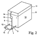
図2は、石油等の液体10のタンク9に接続した、本発明によるエゼクター1を示す。タンク9内の液体10にわたり、液体10の揮発性成分がガス11を形成する。タンク9の底部付近には、管路12を含む液体ループと、液体ポンプ13と、管路7と、エゼクター1と、タンク9にも入る管路5とを配置する。加えて、ガスがあるタンク9の上部付近に管路14を接続し、ガスをポンプ15および管路8を経由してエゼクター1のガス入口に導く。エゼクター1により、タンク9内における液体水平面の上方の空間からのガスを再び液体10に混合させて吸収し、タンク9内の圧力生起を制御下に保持し、液体の損失を低減する。
FIG. 2 shows an
図3は、一般的に、図2と同一であるものの、いくつかのタンク9を縦に列とした集合を示す。この実施態様では、各タンクに接続した主ガス配管16またはガス配管網を、ポンプ15を経由してエゼクター1に接続する。図には示さないが、タンク間で液体を連絡させ、吸収したガスを複数のタンクに分布させることができる。
FIG. 3 shows a set which is generally the same as FIG. 2, but with
図3は、さらに、圧力制御バルブ18が提供されたガス主出口管路317を示す。これは、積載中に圧力を調整し、圧力を比較的高く保持することにより、システムを使用することなくガスを吸収するバルブである。積載中に吸収したガスを輸送中のその後の蒸発において再吸収することができるよう、ガスの積載が完了したところで本システムを使用すべきである。バルブは、タンク内の過大な圧力を考えた安全上についての機能も有する。
FIG. 3 further shows a gas main outlet line 317 provided with a
図3に示すタンクは縦に列として配置されているが、タンクを二つ以上の列または他の構成で配置することもでき、共通の垂直水平面に配置する必要もないことが理解される。 Although the tanks shown in FIG. 3 are arranged vertically in rows, it is understood that the tanks can be arranged in two or more rows or other configurations and need not be arranged in a common vertical horizontal plane.
図4は、図1に示すエゼクターの変形態様を示す。ガス入口の開口または開口4は、この実施態様では、開放回転体14の外表面またはその外表面上に湾曲したベーンもしくはバッフル15を有する対応する輪状部材により、内側に向かって制限される。回転体14は、回転体を配置する管5の径よりもやや小さい径を有し、前記ベーンの半径方向の延長が実質的に管5径の残りの部分を占める。ベーンの湾曲形により、通過するガスが回転するため、回転体14が回転する必要のないことが理解される。回転体14または輪状部材は、中心の孔を有し、液体通路2を取り囲む。
FIG. 4 shows a modification of the ejector shown in FIG. In this embodiment, the gas inlet opening or
図4に示すベーンは、それぞれの前縁において管5軸(および管7軸)と主に平行である。これは、好ましいものの、要件ではない。後縁付近では、ベーン15は、前記軸に対して好ましくは3〜60度の範囲、より好ましくは10〜30度の角度にある。
The vane shown in FIG. 4 is mainly parallel to the
湾曲していないベーンまたはバッフル、すなわちその前縁から後縁までの管5軸に対する角度が固定されている平坦なバッフルまたはベーンを使用することもできる。平坦または湾曲したベーンまたはバッフルは、いずれを使用するかにかかわらず、(回転体周囲を平坦な表面に展開したかのように)回転体14の軸に直角な任意の断面の周囲に沿って考えたときに実質的に平行であることが好ましい。
It is also possible to use a non-curved vane or baffle, i.e. a flat baffle or vane with a fixed angle with respect to the
図1および4は、管7からエゼクターにかけて断面領域が低減し、エゼクターから管5にかけて断面が一定に増加することが明らかなエゼクターを示す。しかし、本発明によるエゼクターの厳密な形状寸法は重大ではない。
FIGS. 1 and 4 show an ejector where the cross-sectional area decreases from
本発明の装置では、エゼクターへの蒸気またはガスの供給系統にコンプレッサーを配置し、より効率的かつ制御可能にエゼクターに蒸気またはガスを送ることが好ましい。 In the apparatus of the present invention, it is preferable to arrange a compressor in the supply system of steam or gas to the ejector so as to send steam or gas to the ejector in a more efficient and controllable manner.
効率的な吸収に加え、図2〜3によるシステムを設置することにより、現在使用されているシステムと比較して有意な効果が提供される。ポンプ室にシステムを設置すると、液体をタンクデッキにポンプする必要がなく、システムを使用するうえでのリスクが有意に低減することになり、漏れを処理するための安全上の設計および「隙間」を有するポンプ室のみで漏れが生じることにもなる。 In addition to efficient absorption, installing the system according to FIGS. 2-3 provides a significant effect compared to currently used systems. Installing a system in the pump room eliminates the need to pump liquid to the tank deck, significantly reducing the risk of using the system, and a safety design and “gap” to handle leaks Leakage may occur only in the pump chamber having
システムは、原理上、保守不要であるものの、大量の沈殿物を含有する液体を処理するための自己洗浄システムを備えることができる。システムが保守不要であるため、タンクの形状寸法上の設計がそのような設置に有利であれば、システムのタンク内への設置を選択することもできる。ガスが大量である場合には、例を挙げれば、例として5〜10個のエゼクターを保持する別個の容器内にエゼクターを平行に組み立てることができる。そのような組み立てにより、システムを拡大縮小し、実際に任意の量のガスを処理することができる。 The system can be equipped with a self-cleaning system for treating liquids that contain large amounts of precipitate, although in principle maintenance-free. Since the system is maintenance-free, the installation of the system in the tank can be selected if the tank geometry design is advantageous for such installation. In the case of large amounts of gas, by way of example, the ejectors can be assembled in parallel in separate containers that hold, for example, 5-10 ejectors. Such assembly allows the system to scale and actually handle any amount of gas.
図は、矩形のタンクを示す。これは、本発明による装置に対して必須ではなく、タンクは、任意の所与の形を有することができる。例として、エゼクターを従来の吸収塔の入口管路に直接的に接続し、したがって、そのような設備の効率の増加に寄与することができる。 The figure shows a rectangular tank. This is not essential for the device according to the invention, and the tank can have any given shape. As an example, an ejector can be connected directly to the inlet line of a conventional absorption tower, thus contributing to an increase in the efficiency of such equipment.
Claims (13)
Applications Claiming Priority (3)
| Application Number | Priority Date | Filing Date | Title |
|---|---|---|---|
| NO20060437A NO325976B1 (en) | 2006-01-26 | 2006-01-26 | Apparatus for absorption of gas or vapor in liquid and method of reintroducing vapor or gas in liquid from which the gas or vapor originates |
| NO20060437 | 2006-01-26 | ||
| PCT/NO2007/000017 WO2007086751A1 (en) | 2006-01-26 | 2007-01-15 | Device for absorption of gas or vapour in a liquid and method for reintroducing vapour or gas in the liquid from which the vapour or gas originates |
Publications (3)
| Publication Number | Publication Date |
|---|---|
| JP2009524518A true JP2009524518A (en) | 2009-07-02 |
| JP2009524518A5 JP2009524518A5 (en) | 2010-01-28 |
| JP5249051B2 JP5249051B2 (en) | 2013-07-31 |
Family
ID=38309458
Family Applications (1)
| Application Number | Title | Priority Date | Filing Date |
|---|---|---|---|
| JP2008552258A Active JP5249051B2 (en) | 2006-01-26 | 2007-01-15 | Apparatus for absorbing gas or vapor into liquid and method for reintroducing vapor or gas into a liquid from which vapor or gas is generated |
Country Status (10)
| Country | Link |
|---|---|
| US (1) | US8641017B2 (en) |
| EP (1) | EP1982106B1 (en) |
| JP (1) | JP5249051B2 (en) |
| KR (2) | KR20080092971A (en) |
| AU (1) | AU2007207929B2 (en) |
| BR (1) | BRPI0707236B1 (en) |
| CA (1) | CA2635207C (en) |
| CY (1) | CY1124305T1 (en) |
| NO (1) | NO325976B1 (en) |
| WO (1) | WO2007086751A1 (en) |
Cited By (4)
| Publication number | Priority date | Publication date | Assignee | Title |
|---|---|---|---|---|
| JP2012021727A (en) * | 2010-07-15 | 2012-02-02 | Tlv Co Ltd | Exhaust steam recovery device |
| JP2012037207A (en) * | 2010-08-11 | 2012-02-23 | Tlv Co Ltd | Waste-steam recovery system |
| JP2014177457A (en) * | 2008-03-21 | 2014-09-25 | General Hospital Corp | Compounds and compositions for detection and treatment of alzheimer's disease and related disorders |
| JP5856341B1 (en) * | 2015-06-26 | 2016-02-09 | 強 下山 | Swirl mixing agitator |
Families Citing this family (11)
| Publication number | Priority date | Publication date | Assignee | Title |
|---|---|---|---|---|
| GB201001525D0 (en) | 2010-01-29 | 2010-03-17 | Hamworthy Combustion Eng Ltd | Improvements in or relating to heating |
| WO2014109013A1 (en) * | 2013-01-09 | 2014-07-17 | 株式会社ロータスプロモーション | Coupler for carbonated spring production |
| CN104533846A (en) * | 2014-12-16 | 2015-04-22 | 中国航天科技集团公司第六研究院第十一研究所 | High pressure annular jet pump suitable for pumping pressure type supply system |
| CN106377985A (en) * | 2016-10-28 | 2017-02-08 | 山西北极熊环境科技有限公司 | Gas-gas mixing aspirator |
| KR102154808B1 (en) * | 2018-07-10 | 2020-09-11 | 한국기계연구원 | Apparatus for diluting exhaust gas |
| US12151219B2 (en) * | 2018-07-25 | 2024-11-26 | Aeromixer, Llc | Aerating and liquid agitating device |
| US11344852B1 (en) * | 2021-06-15 | 2022-05-31 | Enrichment Systems Llc | Hydroponic system and method for enriching a liquid with gas-bubbles |
| NO347417B1 (en) * | 2021-06-18 | 2023-10-23 | Gba Marine As | Gas inlet assembly for oil tanks. |
| KR102569612B1 (en) | 2021-07-20 | 2023-08-25 | 한국기계연구원 | Apparatus for diluting exhaust gas |
| NO348122B1 (en) | 2022-01-12 | 2024-08-26 | Gba Marine As | Device for reintroducing vapour into a volatile liquid |
| DE102022117315A1 (en) * | 2022-07-12 | 2024-01-18 | Messer Se & Co. Kgaa | Device for generating a tempered, cold gas stream |
Citations (2)
| Publication number | Priority date | Publication date | Assignee | Title |
|---|---|---|---|---|
| JPH0686000U (en) * | 1993-05-25 | 1994-12-13 | 宇部興産株式会社 | Ejector |
| JP2000229229A (en) * | 1999-02-09 | 2000-08-22 | Masaru Tsukada | Gas liquid mixing device |
Family Cites Families (25)
| Publication number | Priority date | Publication date | Assignee | Title |
|---|---|---|---|---|
| US3003325A (en) | 1957-10-31 | 1961-10-10 | Bastian Blessing Co | Gas dispensing system |
| GB971563A (en) | 1961-06-07 | 1964-09-30 | Leo Maximilian Bradaska | Improvements in or relating to ejector pumps |
| US3761065A (en) * | 1971-05-21 | 1973-09-25 | Rp Ind Inc | High efficiency direct gas-liquid contact apparatus and methods |
| US4514343A (en) * | 1982-09-29 | 1985-04-30 | Air-O-Lator Corporation | Aspirating horizontal mixer |
| BR8503919A (en) * | 1985-08-16 | 1987-03-24 | Liquid Carbonic Ind Sa | EJECTOR FOR THE CO2 PROCESS IN THE ALKALINE WATER NEUTRALIZATION |
| JPS63319030A (en) | 1987-06-22 | 1988-12-27 | Reika Kogyo Kk | Ejector |
| US5004484A (en) | 1988-08-31 | 1991-04-02 | Barrett, Haentjens & Co. | Air stripping of liquids using high intensity turbulent mixer |
| US4936552A (en) * | 1989-04-27 | 1990-06-26 | Rothrock Charles E | Aerating apparatus |
| JPH0448920A (en) * | 1990-06-18 | 1992-02-18 | Inax Corp | Ejector and purifying apparatus |
| JP3158656B2 (en) * | 1992-06-16 | 2001-04-23 | 株式会社デンソー | Ejector |
| US5403522A (en) * | 1993-11-12 | 1995-04-04 | Von Berg; Richard | Apparatus and methods for mixing liquids and flowable treating agents |
| GB9405000D0 (en) * | 1994-03-15 | 1994-04-27 | Boc Group Plc | Gas dissolving |
| RU2113635C1 (en) * | 1997-06-16 | 1998-06-20 | Сергей Анатольевич Попов | Method of operation of liquid-gas ejector |
| US5951922A (en) * | 1998-02-10 | 1999-09-14 | Mazzei; Angelo L. | Aeration system for substantial bodies of water |
| US20020079384A1 (en) * | 1998-07-27 | 2002-06-27 | Popov Serguei A. | Liquid-gas ejector with an improved liquid nozzle and variants |
| US6237897B1 (en) * | 1999-04-29 | 2001-05-29 | Antonio Marina | Oxygenator |
| NO316045B3 (en) | 1999-12-23 | 2011-05-09 | Venturie As | Process, apparatus and system for the condensation of vapors and gases |
| EP1242769B1 (en) * | 1999-12-23 | 2010-12-15 | Venturie AS | Method, apparatus and system for the condensation of vapours and gases |
| NO312484B1 (en) | 2000-07-26 | 2002-05-13 | Venturie As | Gasskondensator |
| DE10121768B4 (en) * | 2001-05-04 | 2007-03-01 | Robert Bosch Gmbh | Mixing device for gases in fuel cells |
| US6539884B1 (en) * | 2001-05-25 | 2003-04-01 | Mh Systems Corporation | Closed loop control of volatile organic compound emissions from the tanks of oil tankers, including as may be simultaneously safeguarded from spillage of oil by an underpressure system |
| JP4048312B2 (en) | 2001-06-06 | 2008-02-20 | 日立造船株式会社 | Ejecta |
| NO315293B1 (en) | 2001-10-31 | 2003-08-11 | Procyss As | Process for absorbing vapors and gases in the control of overpressure storage tanks for liquids and application of the process |
| NO315417B1 (en) | 2001-12-06 | 2003-09-01 | Knutsen Oas Shipping As | Method and arrangement of loading column |
| KR100441857B1 (en) * | 2002-03-14 | 2004-07-27 | 대우조선해양 주식회사 | Boil off gas rel iquefaction method and system assembly of Liquefied natural gas carrier |
-
2006
- 2006-01-26 NO NO20060437A patent/NO325976B1/en unknown
-
2007
- 2007-01-15 KR KR1020087020797A patent/KR20080092971A/en not_active Application Discontinuation
- 2007-01-15 AU AU2007207929A patent/AU2007207929B2/en active Active
- 2007-01-15 JP JP2008552258A patent/JP5249051B2/en active Active
- 2007-01-15 CA CA2635207A patent/CA2635207C/en active Active
- 2007-01-15 WO PCT/NO2007/000017 patent/WO2007086751A1/en active Application Filing
- 2007-01-15 BR BRPI0707236A patent/BRPI0707236B1/en active IP Right Grant
- 2007-01-15 US US12/159,257 patent/US8641017B2/en active Active
- 2007-01-15 KR KR1020137013131A patent/KR20130090417A/en active Search and Examination
- 2007-01-15 EP EP07709200.5A patent/EP1982106B1/en active Active
-
2021
- 2021-06-14 CY CY20211100611T patent/CY1124305T1/en unknown
Patent Citations (2)
| Publication number | Priority date | Publication date | Assignee | Title |
|---|---|---|---|---|
| JPH0686000U (en) * | 1993-05-25 | 1994-12-13 | 宇部興産株式会社 | Ejector |
| JP2000229229A (en) * | 1999-02-09 | 2000-08-22 | Masaru Tsukada | Gas liquid mixing device |
Cited By (4)
| Publication number | Priority date | Publication date | Assignee | Title |
|---|---|---|---|---|
| JP2014177457A (en) * | 2008-03-21 | 2014-09-25 | General Hospital Corp | Compounds and compositions for detection and treatment of alzheimer's disease and related disorders |
| JP2012021727A (en) * | 2010-07-15 | 2012-02-02 | Tlv Co Ltd | Exhaust steam recovery device |
| JP2012037207A (en) * | 2010-08-11 | 2012-02-23 | Tlv Co Ltd | Waste-steam recovery system |
| JP5856341B1 (en) * | 2015-06-26 | 2016-02-09 | 強 下山 | Swirl mixing agitator |
Also Published As
| Publication number | Publication date |
|---|---|
| EP1982106A1 (en) | 2008-10-22 |
| CY1124305T1 (en) | 2022-07-22 |
| NO20060437L (en) | 2007-07-27 |
| CA2635207C (en) | 2014-04-08 |
| BRPI0707236B1 (en) | 2019-02-05 |
| CA2635207A1 (en) | 2007-08-02 |
| US8641017B2 (en) | 2014-02-04 |
| KR20080092971A (en) | 2008-10-16 |
| EP1982106A4 (en) | 2017-05-03 |
| JP5249051B2 (en) | 2013-07-31 |
| EP1982106B1 (en) | 2021-04-28 |
| US20090306440A1 (en) | 2009-12-10 |
| BRPI0707236A2 (en) | 2011-04-26 |
| AU2007207929A1 (en) | 2007-08-02 |
| WO2007086751A1 (en) | 2007-08-02 |
| KR20130090417A (en) | 2013-08-13 |
| AU2007207929B2 (en) | 2012-02-16 |
| NO325976B1 (en) | 2008-08-25 |
Similar Documents
| Publication | Publication Date | Title |
|---|---|---|
| JP5249051B2 (en) | Apparatus for absorbing gas or vapor into liquid and method for reintroducing vapor or gas into a liquid from which vapor or gas is generated | |
| KR101918906B1 (en) | Fuel tank arrangement of marine vessel | |
| CN106794384B (en) | Evaporation system, evaporation method and sealing system | |
| KR20210142103A (en) | A fuel tank arrangement on a ship and a method of relieving hydrogen from a liquid hydrogen fuel tank arrangement | |
| KR102222221B1 (en) | Arrangement of fuel tanks on a ship | |
| KR101494118B1 (en) | Liquid suction device | |
| KR101291357B1 (en) | VOC reducing apparatus for liquid cargo storage tank | |
| KR20170120835A (en) | Vessel | |
| KR101278912B1 (en) | Pressure adjusting valve for reducing voc in the tanker | |
| US10618018B2 (en) | Low wear radial flow impeller device and system | |
| GB2103926A (en) | Tank ventilating method and apparatus | |
| US20240262616A1 (en) | Gas Inlet Assembly for Oil Tanks | |
| JP2025505891A (en) | Apparatus for reintroducing vapor into a volatile liquid | |
| JP7152957B2 (en) | Marine boiler and modification method of marine boiler | |
| KR20130057322A (en) | Apparatus for producing fuel gas and container type liquefied gas tank and container ship including the same | |
| KR20250009205A (en) | Ventilation System For Double Wall Pipe Of Ship | |
| KR20250015810A (en) | Wind-propelled System and Ship having the same | |
| KR20240128306A (en) | LPG storage tank for small vessel | |
| KR20230000562A (en) | Apparatus for cooling emission vapor in the reactor | |
| JP2005194432A (en) | Regasification apparatus of gas hydrate | |
| KR20130002164U (en) | / vent device system for boil off gas of fpso/gas fpso |
Legal Events
| Date | Code | Title | Description |
|---|---|---|---|
| A521 | Request for written amendment filed |
Free format text: JAPANESE INTERMEDIATE CODE: A523 Effective date: 20091204 |
|
| A621 | Written request for application examination |
Free format text: JAPANESE INTERMEDIATE CODE: A621 Effective date: 20091204 |
|
| A977 | Report on retrieval |
Free format text: JAPANESE INTERMEDIATE CODE: A971007 Effective date: 20110112 |
|
| A131 | Notification of reasons for refusal |
Free format text: JAPANESE INTERMEDIATE CODE: A131 Effective date: 20110118 |
|
| A601 | Written request for extension of time |
Free format text: JAPANESE INTERMEDIATE CODE: A601 Effective date: 20110415 |
|
| A602 | Written permission of extension of time |
Free format text: JAPANESE INTERMEDIATE CODE: A602 Effective date: 20110422 |
|
| A521 | Request for written amendment filed |
Free format text: JAPANESE INTERMEDIATE CODE: A523 Effective date: 20110513 |
|
| A02 | Decision of refusal |
Free format text: JAPANESE INTERMEDIATE CODE: A02 Effective date: 20120221 |
|
| A521 | Request for written amendment filed |
Free format text: JAPANESE INTERMEDIATE CODE: A523 Effective date: 20120621 |
|
| A521 | Request for written amendment filed |
Free format text: JAPANESE INTERMEDIATE CODE: A523 Effective date: 20120705 |
|
| A911 | Transfer to examiner for re-examination before appeal (zenchi) |
Free format text: JAPANESE INTERMEDIATE CODE: A911 Effective date: 20120712 |
|
| A912 | Re-examination (zenchi) completed and case transferred to appeal board |
Free format text: JAPANESE INTERMEDIATE CODE: A912 Effective date: 20120921 |
|
| A521 | Request for written amendment filed |
Free format text: JAPANESE INTERMEDIATE CODE: A523 Effective date: 20130228 |
|
| A61 | First payment of annual fees (during grant procedure) |
Free format text: JAPANESE INTERMEDIATE CODE: A61 Effective date: 20130411 |
|
| R150 | Certificate of patent or registration of utility model |
Ref document number: 5249051 Country of ref document: JP Free format text: JAPANESE INTERMEDIATE CODE: R150 Free format text: JAPANESE INTERMEDIATE CODE: R150 |
|
| FPAY | Renewal fee payment (event date is renewal date of database) |
Free format text: PAYMENT UNTIL: 20160419 Year of fee payment: 3 |
|
| R250 | Receipt of annual fees |
Free format text: JAPANESE INTERMEDIATE CODE: R250 |
|
| R250 | Receipt of annual fees |
Free format text: JAPANESE INTERMEDIATE CODE: R250 |
|
| R250 | Receipt of annual fees |
Free format text: JAPANESE INTERMEDIATE CODE: R250 |
|
| R250 | Receipt of annual fees |
Free format text: JAPANESE INTERMEDIATE CODE: R250 |
|
| R250 | Receipt of annual fees |
Free format text: JAPANESE INTERMEDIATE CODE: R250 |
|
| R250 | Receipt of annual fees |
Free format text: JAPANESE INTERMEDIATE CODE: R250 |
|
| R250 | Receipt of annual fees |
Free format text: JAPANESE INTERMEDIATE CODE: R250 |
|
| R250 | Receipt of annual fees |
Free format text: JAPANESE INTERMEDIATE CODE: R250 |
|
| R250 | Receipt of annual fees |
Free format text: JAPANESE INTERMEDIATE CODE: R250 |