JP2009178362A - Cooking apparatus - Google Patents
Cooking apparatus Download PDFInfo
- Publication number
- JP2009178362A JP2009178362A JP2008020504A JP2008020504A JP2009178362A JP 2009178362 A JP2009178362 A JP 2009178362A JP 2008020504 A JP2008020504 A JP 2008020504A JP 2008020504 A JP2008020504 A JP 2008020504A JP 2009178362 A JP2009178362 A JP 2009178362A
- Authority
- JP
- Japan
- Prior art keywords
- heating
- time
- display
- charge
- cooking utensil
- Prior art date
- Legal status (The legal status is an assumption and is not a legal conclusion. Google has not performed a legal analysis and makes no representation as to the accuracy of the status listed.)
- Pending
Links
- 238000010411 cooking Methods 0.000 title claims abstract description 56
- 238000010438 heat treatment Methods 0.000 claims abstract description 54
- 239000004973 liquid crystal related substance Substances 0.000 abstract description 12
- XLYOFNOQVPJJNP-UHFFFAOYSA-N water Substances O XLYOFNOQVPJJNP-UHFFFAOYSA-N 0.000 description 32
- 238000009835 boiling Methods 0.000 description 26
- 241000209094 Oryza Species 0.000 description 24
- 235000007164 Oryza sativa Nutrition 0.000 description 24
- 235000009566 rice Nutrition 0.000 description 24
- 238000000034 method Methods 0.000 description 15
- 230000002093 peripheral effect Effects 0.000 description 9
- 229920003002 synthetic resin Polymers 0.000 description 8
- 239000000057 synthetic resin Substances 0.000 description 8
- 230000001681 protective effect Effects 0.000 description 7
- 230000005611 electricity Effects 0.000 description 6
- 238000009413 insulation Methods 0.000 description 6
- 238000001514 detection method Methods 0.000 description 4
- 238000010586 diagram Methods 0.000 description 4
- 230000000694 effects Effects 0.000 description 3
- 238000005338 heat storage Methods 0.000 description 3
- 238000012856 packing Methods 0.000 description 3
- 239000010935 stainless steel Substances 0.000 description 3
- 229910001220 stainless steel Inorganic materials 0.000 description 3
- 239000003990 capacitor Substances 0.000 description 2
- 239000000463 material Substances 0.000 description 2
- 229910052751 metal Inorganic materials 0.000 description 2
- 239000002184 metal Substances 0.000 description 2
- 239000010445 mica Substances 0.000 description 2
- 229910052618 mica group Inorganic materials 0.000 description 2
- 238000003825 pressing Methods 0.000 description 2
- 238000003303 reheating Methods 0.000 description 2
- 238000007789 sealing Methods 0.000 description 2
- 229910000838 Al alloy Inorganic materials 0.000 description 1
- 230000002159 abnormal effect Effects 0.000 description 1
- 230000003466 anti-cipated effect Effects 0.000 description 1
- 235000021152 breakfast Nutrition 0.000 description 1
- 235000021329 brown rice Nutrition 0.000 description 1
- 239000000919 ceramic Substances 0.000 description 1
- 239000004020 conductor Substances 0.000 description 1
- 238000001816 cooling Methods 0.000 description 1
- 230000005674 electromagnetic induction Effects 0.000 description 1
- 238000009499 grossing Methods 0.000 description 1
- 239000000696 magnetic material Substances 0.000 description 1
- 230000005389 magnetism Effects 0.000 description 1
- 235000012054 meals Nutrition 0.000 description 1
- 235000021395 porridge Nutrition 0.000 description 1
- 238000010025 steaming Methods 0.000 description 1
- 239000000758 substrate Substances 0.000 description 1
- 230000001360 synchronised effect Effects 0.000 description 1
- 238000010792 warming Methods 0.000 description 1
- 229910000859 α-Fe Inorganic materials 0.000 description 1
Images


Landscapes
- Electric Ovens (AREA)
- Cookers (AREA)
Abstract
Description
本願発明は、加熱手段と、該加熱手段の加熱制御を行う制御手段と、前記加熱手段の使用状態および時刻等を表示する表示手段とを備えた調理器具に関するものである。 The present invention relates to a cooking utensil comprising heating means, control means for controlling heating of the heating means, and display means for displaying the use state and time of the heating means.
近年、割安な深夜電力を利用したエコ給湯が普及してきており、オール電化にした世帯では深夜の低料金時間帯に電気製品を使うように心掛けている消費者が増えてきている。 In recent years, eco hot water supply using cheap late-night electricity has become widespread, and an increasing number of consumers are trying to use electrical products in low-cost hours late at night in all-electric households.
ところが、従来のこの種調理器具の場合、上記した深夜の低料金時間帯に調理器具を使うということはなく、例えば、ユーザは必要に応じて調理器具を使用するのが一般的であった。例えば、調理器具の一つである電気貯湯容器の場合、沸騰時に極めて大きな電力を必要とするが、時間に関係なく沸騰させることが行われていた(特許文献1参照)。 However, in the case of this kind of conventional cooking utensils, the cooking utensils are not used in the above-mentioned low-cost time zone at midnight. For example, the user generally uses the cooking utensils as needed. For example, in the case of an electric hot water storage container that is one of cooking utensils, extremely large electric power is required at the time of boiling, but boiling has been performed regardless of time (see Patent Document 1).
本願発明は、上記の点に鑑みてなされたもので、電力会社が提供する低料金プランに沿った加熱制御を行うことによって、消費電力料金を低く抑え得るようにした調理器具を提供することを目的とするものである。 The present invention has been made in view of the above points, and is to provide a cooking utensil that can keep the power consumption fee low by performing heating control in accordance with a low rate plan provided by an electric power company. It is the purpose.
本願発明では、上記課題を解決するための第1の手段として、加熱手段と、該加熱手段の加熱制御を行う制御手段と、前記加熱手段の使用状態および時刻等を表示する表示手段とを備えた調理器具において、前記制御手段を、電力会社が提供する低料金プランに合った時間帯に沿って前記加熱手段の加熱制御を行い得るうように構成している。 In the present invention, as a first means for solving the above-mentioned problems, a heating means, a control means for controlling the heating of the heating means, and a display means for displaying the use state and time of the heating means are provided. In the cooking utensil, the control means is configured to perform heating control of the heating means along a time zone suitable for a low price plan provided by an electric power company.
上記のように構成したことにより、電力会社が提供する低料金プランに合った時間帯に沿って加熱手段の加熱制御が行われることとなり、家庭での電力使用料金の低減を図ることができる。 With the configuration described above, heating control of the heating means is performed along a time zone suitable for a low-price plan provided by the electric power company, so that it is possible to reduce the electricity usage fee at home.
本願発明では、さらに、上記課題を解決するための第2の手段として、上記第1の手段を備えた調理器具において、前記表示手段を、現在の時刻が電力会社の提供する料金プラン毎のどの時間帯であるかを表示し得るように構成することもでき、そのように構成した場合、表示手段への表示を確認することにより、ユーザに現在時刻がどの料金時間帯なのかを知らせることができ、調理器具の使用時間帯をユーザが決定し易くなる。 In the present invention, as a second means for solving the above-described problem, in the cooking utensil provided with the first means, the display means is set to indicate which of the charge plans provided by the electric power company the current time is. It can also be configured to be able to display whether it is a time zone, in which case it is possible to inform the user of which charge time zone the current time is by checking the display on the display means This makes it easier for the user to determine the usage time zone of the cooking utensil.
本願発明では、さらに、上記課題を解決するための第3の手段として、上記第1又は第2の手段を備えた調理器具において、前記表示手段を、前記加熱手段の使用状態を表示し得るように構成することもでき、そのように構成した場合、表示手段への表示を確認することにより、ユーザに加熱手段の使用状態を知らせることができ、調理器具の使用状態をユーザが確認し易くなる。 In the present invention, as a third means for solving the above-described problem, in the cooking utensil provided with the first or second means, the display means can display the use state of the heating means. In such a case, by confirming the display on the display means, the user can be informed of the use state of the heating means, and the user can easily confirm the use state of the cooking utensil. .
本願発明では、さらに、上記課題を解決するための第4の手段として、上記第1、第2又は第3の手段を備えた調理器具において、仕上がり時刻を設定する設定手段を付設するとともに、該設定手段により設定される仕上がり時刻が前記低料金プランにおける最低料金帯をはずれている場合には、前記表示手段の表示を、最低料金帯内に仕上がるように表示変更し得るように構成することもでき、そのように構成した場合、表示手段の表示を最低料金時間帯内に仕上がるように表示変更することにより、設定手段による設定の誤りをユーザに知らせることができ、調理器具の仕上がり時刻を常時最低料金時間帯内に設定し直すことができる。 In the present invention, as a fourth means for solving the above problems, in the cooking utensil provided with the first, second or third means, a setting means for setting a finishing time is attached, When the finishing time set by the setting means is out of the minimum charge zone in the low charge plan, the display of the display means can be changed so that the display is finished within the minimum charge band. In such a case, by changing the display so that the display on the display means is finished within the minimum charge time zone, it is possible to inform the user of an error in the setting by the setting means, and the finish time of the cooking utensil is always It can be reset within the minimum charge period.
本願発明では、さらに、上記課題を解決するための第5の手段として、上記第1、第2、第3又は第4の手段を備えた調理器具において、前記制御手段を、前記低料金プランにおける低料金時間帯終了前に大きな消費電力を必要とするモードに入り、通常料金時間帯および高料金時間帯においてはその状態を維持するように制御し得るように構成することもでき、そのように構成した場合、低料金プランにおける低料金時間帯終了前に大きな消費電力を必要とするモードに入り、通常料金時間帯および高料金時間帯においてはその状態を維持するように制御し得ることとなり、家庭での電力使用料金のさらなる低減を図ることができる。 In the present invention, as a fifth means for solving the above-mentioned problems, in the cooking utensil provided with the first, second, third or fourth means, the control means is set in the low-price plan. It can be configured so that it can be controlled to enter a mode that requires a large amount of power consumption before the end of the low charge period, and to maintain the state in the normal charge period and the high charge period. When configured, it can be controlled to enter a mode that requires large power consumption before the end of the low charge period in the low charge plan, and to maintain that state in the normal charge time period and the high charge time period, It is possible to further reduce the electricity usage fee at home.
本願発明の第1の手段によれば、加熱手段と、該加熱手段の加熱制御を行う制御手段と、前記加熱手段の使用状態および時刻等を表示する表示手段とを備えた調理器具において、前記制御手段を、電力会社が提供する低料金プランに合った時間帯に沿って前記加熱手段の加熱制御を行い得るうように構成し、電力会社が提供する低料金プランに合った時間帯に沿って加熱手段の加熱制御が行われるようにしたので、家庭での電力使用料金の低減を図ることができるという効果がある。 According to the first means of the present invention, in a cooking utensil comprising a heating means, a control means for performing heating control of the heating means, and a display means for displaying a use state and time of the heating means, The control means is configured to be able to perform heating control of the heating means along a time zone suitable for a low price plan provided by the electric power company, and along a time zone suitable for the low price plan provided by the electric power company. Since the heating control of the heating means is performed, there is an effect that it is possible to reduce the electricity usage fee at home.
本願発明の第2の手段におけるように、上記第1の手段を備えた調理器具において、前記表示手段を、現在の時刻が電力会社の提供する料金プラン毎のどの時間帯であるかを表示し得るように構成することもでき、そのように構成した場合、表示手段への表示を確認することにより、ユーザに現在時刻がどの料金時間帯なのかを知らせることができ、調理器具の使用時間帯をユーザが決定し易くなる。 As in the second means of the present invention, in the cooking utensil provided with the first means, the display means displays the time zone for each rate plan provided by the electric power company. In such a case, by confirming the display on the display means, it is possible to inform the user of which charge time zone the current time is and Can be easily determined by the user.
本願発明の第3の手段におけるように、上記第1又は第2の手段を備えた調理器具において、前記表示手段を、前記加熱手段の使用状態を表示し得るように構成することもでき、そのように構成した場合、表示手段への表示を確認することにより、ユーザに加熱手段の使用状態を知らせることができ、調理器具の使用状態をユーザが確認し易くなる。 As in the third means of the present invention, in the cooking utensil provided with the first or second means, the display means can be configured to display the use state of the heating means, When comprised in this way, by confirming the display on a display means, a user can be notified of the use condition of a heating means, and it becomes easy for a user to confirm the use condition of a cooking utensil.
本願発明の第4の手段におけるように、上記第1、第2又は第3の手段を備えた調理器具において、仕上がり時刻を設定する設定手段を付設するとともに、該設定手段により設定される仕上がり時刻が前記低料金プランにおける最低料金帯をはずれている場合には、前記表示手段の表示を、最低料金帯内に仕上がるように表示変更し得るように構成することもでき、そのように構成した場合、表示手段の表示を最低料金時間帯内に仕上がるように表示変更することにより、設定手段による設定の誤りをユーザに知らせることができ、調理器具の仕上がり時刻を常時最低料金時間帯内に設定し直すことができる。 As in the fourth means of the present invention, in the cooking utensil provided with the first, second or third means, a setting means for setting the finishing time is attached, and the finishing time set by the setting means Can be configured so that the display of the display means can be changed so that the display is finished within the minimum fee zone when the minimum fee zone in the low fee plan is deviated. By changing the display of the display means so that it is finished within the minimum charge time zone, it is possible to inform the user of the setting error by the setting means, and the finish time of the cooking utensil is always set within the minimum charge time zone. You can fix it.
本願発明の第5の手段におけるように、上記第1、第2、第3又は第4の手段を備えた調理器具において、前記制御手段を、前記低料金プランにおける低料金時間帯終了前に大きな消費電力を必要とするモードに入り、通常料金時間帯および高料金時間帯においてはその状態を維持するように制御し得るように構成することもでき、そのように構成した場合、低料金プランにおける低料金時間帯終了前に大きな消費電力を必要とするモードに入り、通常料金時間帯および高料金時間帯においてはその状態を維持するように制御し得ることとなり、家庭での電力使用料金のさらなる低減を図ることができる。 As in the fifth means of the present invention, in the cooking utensil provided with the first, second, third or fourth means, the control means is large before the low charge time period in the low charge plan ends. It can be configured to enter a mode that requires power consumption, and can be controlled to maintain its state in the normal charge time zone and the high charge time zone. It will be possible to enter a mode that requires a large amount of power consumption before the end of the low charge period, and to maintain that state in the normal charge period and the high charge period. Reduction can be achieved.
以下、添付の図面を参照して、本願発明の幾つかの好適な実施の形態について詳述する。 Hereinafter, some preferred embodiments of the present invention will be described in detail with reference to the accompanying drawings.
第1の実施の形態
図1ないし図3には、本願発明の第1の実施の形態にかかる調理器具の具体例である電気貯湯容器が示されている。
1st Embodiment The electric hot water storage container which is a specific example of the cooking utensil concerning the 1st Embodiment of this invention is shown by FIG. 1 thru | or FIG.
この電気貯湯容器は、図1に示すように、湯沸かし用の内容器3を備えた容器本体1と、該容器本体1の上部開口を開閉する蓋体2と、前記内容器3の底部を加熱する加熱手段である電気ヒータ4と、前記内容器3内のお湯を外部へ給湯するための給湯通路5と、該給湯通路5の途中に設けられたポンプ装置である電動ポンプ6とを備えて構成されている。
As shown in FIG. 1, this electric hot water storage container heats a
前記容器本体1は、外側面を構成する合成樹脂製の外ケース7と、内周面を構成する前記内容器3と、前記外ケース7の上部と内容器3の上部とを結合する合成樹脂製の環状の肩部材8と、底面を構成する合成樹脂製の底板9とからなっている。
The
前記内容器3は、ステンレス製の有底円筒形状の内筒10とステンレス製の略円筒形状の外筒11との間に真空空間12を形成してなる真空二重容器からなっており、その底部には、前記内筒10の底部のみからなる非真空部3aが形成されている。該非真空部3aの下面には、前記電気ヒータ4(例えば、雲母板に発熱体を保持させてなるマイカヒータ)が取り付けられている。符号13は内容器3の温度(換言すれば、湯温T)を検出する温度検出手段として作用する温度センサーである。
The
前記蓋体2は、合成樹脂製の上板14と該上板14に対して外周縁が嵌め合いにより結合された合成樹脂製の下板15とからなっており、前記肩部材8の後部に設けられたヒンジ受け16に対してヒンジピン17を介して開閉且つ着脱自在に支持されている。
The
また、この蓋体2には、電源が接続されていない状態でも給湯通路5を介しての給湯が可能なように、手動操作により駆動されるエアーポンプ18が配設されている。該エアーポンプ18は、前記蓋体2の略中央部に形成された円筒形状の凹部19内に配設されたベーローズタイプのものとされており、押圧板20を介しての押圧操作により加圧空気が内容器3内に吹き込まれ、該加圧空気の圧力により内容器3内のお湯が給湯通路5を介して外部へ押し出されることとなっている。符号21は蒸気排出通路、22は蒸気排出通路21の途中に配設された転倒止水弁である。
The
前記蓋体2における下板15には、金属製のカバー部材23が固定されており、該カバー部材23の外周縁には、蓋体2の閉蓋時において前記内容器3の給水口3bに圧接されるシールパッキン24が設けられている。
A
前記給湯通路5の途中であって前記内容器3の下方位置には、前記電動ポンプ6が配設されている。また、前記給湯通路5の途中であって満水位表示部25より上方位置には、転倒時止水弁26および前傾時止水弁27が設けられている。
The
上記構成の電気貯湯容器は、保温用ヒータ4Bへの通電制御を行う通常の保温モード(換言すれば、設定保温温度制御モード)の他に、沸騰用ヒータ4Aおよび保温用ヒータ4Bへの通電を停止した状態(例えば、電源コードを取り外した状態)で保温する魔法瓶保温モードによる使用が可能となっている。
The electric hot water storage container having the above configuration supplies power to the boiling
図1において、符号28は蓋体2を容器本体1に対して閉止状態に保持するためのロック機構、29は後述する各種スイッチ類を備えた操作パネル部、30はスイッチ基板である。
In FIG. 1,
前記操作パネル部29には、図2に示すように、給湯スイッチ31、ロック解除スイッチ32、再沸騰スイッチ33、保温選択スイッチ34、深夜電力モードスイッチ35、液晶表示装置36、再沸騰表示灯37、保温表示灯38、深夜電力モード選択表示灯39、低料金帯表示灯40、標準料金帯表示灯41、高料金帯表示灯42が設けられている。ここで、深夜電力モードとは、電力会社が提供する割り引きの深夜(23時〜翌朝7時まで)の電力を使用したい時に選択するモードのことであり、低料金帯とは、電力会社が提供する料金プランでの低料金時間帯(例えば、23時〜翌朝7時まで)での使用のことであり、標準料金帯とは、電力会社が提供する料金プランでの標準料金時間帯(例えば、平日:7時〜10時および17時〜23時、休日:7時〜23時)での使用のことであり、高料金帯とは、電力会社が提供する料金プランでの高料金時間帯(例えば、平日:10時〜17時)での使用のことである。前記液晶表示装置36には、加熱手段である電気ヒータ4の使用状態、温度、沸騰残時間および湯量が交互に7セグメント表示される。
As shown in FIG. 2, the
図3は、本実施の形態にかかる電気貯湯容器における電気的要素の結線状態を示すブロック図である。なお、既に説明した電気的要素については同一の符号を付して説明を省略する。 FIG. 3 is a block diagram showing a connection state of electrical elements in the electric hot water storage container according to the present embodiment. In addition, about the electrical element already demonstrated, the same code | symbol is attached | subjected and description is abbreviate | omitted.
図3において、符号43は制御手段および設定手段として作用するマイコン基板、44は交流電源、45は温度ヒューズ、46はトライアック、47はリレー、48は抵抗である。
In FIG. 3,
上記のように構成された電気貯湯容器においては、次のような作用効果が得られる。 In the electric hot water storage container configured as described above, the following operational effects are obtained.
深夜電力モードスイッチ35がON操作されると、電力会社が提供する低料金プランに合った時間帯に沿って電気ヒータ4の加熱制御が行われる。
When the midnight
例えば、ユーザの生活パターンに合わせて電気ヒータのON/OFF制御を行う「とく子さんコース」の使用時間帯開始時刻と電力会社が提供する料金プランにおいて料金が高くなる時間帯との間の時間が所定時間t以内である場合、「とく子さんコース」の使用時間帯開始時刻よりも前倒しして料金プランの安い時間帯に電気ヒータ4の制御が開始される(図4参照)。図4の場合、電力会社の低料金時間帯は23時〜6時とされ、「とく子さんコース」の使用時間帯開始時刻は7時としている。 For example, the time between the use time zone start time of “Tokuko-san course” that performs ON / OFF control of the electric heater according to the life pattern of the user and the time zone when the charge is high in the charge plan provided by the power company If it is within the predetermined time t, the control of the electric heater 4 is started in a time zone where the price plan is cheaper ahead of the use time zone start time of the “Tokuko-san course” (see FIG. 4). In the case of FIG. 4, the low charge time zone of the electric power company is from 23:00 to 6:00, and the use time zone start time of the “Tokuko-san course” is 7:00.
このようにすると、電力会社が提供する低料金プランに合った時間帯に沿って電気ヒータ4の加熱制御が行われることとなり、家庭での電力使用料金の低減を図ることができる。 If it does in this way, heating control of the electric heater 4 will be performed along the time slot | zone according to the low charge plan which an electric power company provides, and reduction of the electric power usage charge at home can be aimed at.
つまり、低料金時間帯(例えば、23時〜7時):設定温度保温又は魔法瓶保温+時間帯終了前に沸騰制御、標準料金時間帯(例えば、平日:7時〜10時および17時〜23時、休日:7時〜23時):設定温度保温、高料金時間帯(例えば、平日:10時〜17時):強制魔法瓶保温又は設定温度保温とされる。 That is, low charge time zone (for example, from 23:00 to 7 o'clock): set temperature or thermos bottle temperature + boiling control before the end of the time zone, standard charge time zone (for example, weekdays: 7 o'clock to 10 o'clock and 17 o'clock to 23 o'clock) Hours, holidays: 7:00 to 23:00): set temperature insulation, high charge time zone (for example, weekdays: 10:00 to 17:00): forced thermos insulation or set temperature insulation.
このとき、表示手段として作用する低料金帯表示灯40、標準料金帯表示灯41、高料金帯表示灯42が点灯することにより、現在の時刻が電力会社の提供する料金プラン毎のどの時間帯であるかが表示される。前記表示灯40〜42として「緑」、「黄」、「赤」の発光LEDを用いると、ユーザの表示認識がより明確となる。なお、1個の3色発光LEDによって、料金時間帯によって発光色が「緑」、「黄」、「赤」と変化するようにしてもよい。
At this time, the low charge
ついで、本実施の形態における沸騰加熱について図5および図6に示すフローチャートを参照して説明する。
(1) 深夜電力モードでの沸騰制御(図5のフローチャート参照)
ステップS1において深夜電力モードスイッチ35がON操作されたことが確認されると、ステップS2において自動沸騰予定時刻が液晶表示装置36に表示される。この自動沸騰予定時刻は、設定手段により電力会社が提供する料金プランのうち低料金時間帯終了前に沸騰が完了する時刻に設定される。ついで、ステップS3において現在時刻が自動沸騰予定時刻に到達したか否かの判定がなされ、ここで肯定判定されると、ステップS4において沸騰工程へ移行する。
Next, boiling heating in the present embodiment will be described with reference to the flowcharts shown in FIGS.
(1) Boiling control in the midnight power mode (refer to the flowchart in FIG. 5)
When it is confirmed in step S1 that the midnight
このようにすると、大きな消費電力を必要とする沸騰工程が低料金時間帯終了前行われることとなり、家庭での電力使用料金のさらなる低減を図ることができる。
(2) 再沸騰時の沸騰制御(図6のフローチャート参照)
保温工程中において、ステップS1において再沸騰スイッチ33がON操作されたことが確認されると、ステップS2において深夜電力モード中が否かの判定がなされ、ここで否定判定されると、ステップS3において再沸騰工程に移行するが、肯定判定されると、ステップS4において電力会社が提供する料金プランにおける低料金時間帯であるか否かの判定がなされる。ここで、肯定判定されると、ステップS5において再沸騰肯定に移行するが、否定判定されると、ステップS6においてタイマーが作動開始され、ステップS7において「ピピピッ」との警報が発せられ、ステップS8において液晶表示装置36に「低料金時間帯外再沸騰OK?」が表示される。ついで、ステップS9において再沸騰スイッチ33が再度ONされたか否かの判定がなされ、ここで、肯定判定されると、ステップS10において再沸騰肯定へ移行するが、否定判定された場合、ステップS11においてタイマーが3秒経過したことが確認されると、ステップS12において液晶表示装置36における「低料金時間帯外再沸騰OK?」との表示が解除され、ステップS13において保温工程に戻る。
If it does in this way, the boiling process which requires big power consumption will be performed before the end of a low charge time zone, and it can aim at the further reduction of the electric power usage charge at home.
(2) Boiling control during re-boiling (refer to the flowchart in FIG. 6)
If it is confirmed that the reboiling switch 33 is turned on in step S1 during the heat retaining process, it is determined in step S2 whether or not the midnight power mode is in progress. If a negative determination is made here, in step S3. Although the process proceeds to the re-boiling process, if an affirmative determination is made, it is determined in step S4 whether or not it is a low charge time zone in the charge plan provided by the electric power company. Here, if an affirmative determination is made, the process proceeds to re-boiling affirmation in step S5, but if a negative determination is made, the timer starts operating in step S6, an alarm of “beep” is issued in step S7, and step S8. , “Low-fee out-of-period re-boiling OK?” Is displayed on the liquid
上記のようにすると、深夜電力モードが選択されているときに再沸騰スイッチ33がON操作された場合には、必要最小限の場合に限って再沸騰が実行されることとなる。従って、家庭での電力使用料金のさらなる低減を図ることができる。また、表示手段である液晶表示装置36の表示を最低料金時間帯内に仕上がるように表示変更することにより、設定手段として作用するマイコン基板34による設定の誤りをユーザに知らせることができ、調理器具の仕上がり時刻を常時最低料金時間帯内に設定し直すことができる。
As described above, when the re-boiling switch 33 is turned on when the midnight power mode is selected, the re-boiling is executed only in the minimum necessary case. Therefore, it is possible to further reduce the electricity usage fee at home. Further, by changing the display of the liquid
第2の実施の形態
図7ないし図9には、本願発明の第2の実施の形態にかかる調理器具の具体例である電気炊飯器が示されている。
Second Embodiment FIGS. 7 to 9 show an electric rice cooker which is a specific example of a cooking utensil according to a second embodiment of the present invention.
この電気炊飯器は、図7に示すように、米と水とを収容する内鍋53を取出自在に収納し得るように構成され且つ空間部を有する二重構造の炊飯器本体51と、該炊飯器本体51の上部開口を開閉自在に覆蓋する蓋体52とを備えている。
As shown in FIG. 7, this electric rice cooker is configured to be able to take out an
前記炊飯器本体51は、外側壁を構成する合成樹脂製の外ケース51aと、底壁を構成する合成樹脂製の底ケース51bと、肩部を構成する合成樹脂製の肩部材51cと、内周壁を構成する合成樹脂製の有底筒状の保護枠54とからなっている。なお、前記保護枠54内には、前記内鍋3が取り出し可能に収納されることとなっている。
The
前記保護枠54の外周面側には、炊飯時における主加熱手段として作用する環状のメインIHコイルC1,C2,C3が保護枠54の底面、該底面から側周面に至る間の湾曲部および側周面にそれぞれ対応して配設されている。該メインIHコイルC1,C2,C3は、交番磁界(換言すれば、電磁波)を発生するものであり、該交番磁界の電磁誘導により前記内鍋53に誘導渦電流を発生させ、該誘導渦電流の抵抗熱を利用して加熱するものとされている。なお、内鍋53は、メインIHコイルC1,C2,C3により誘導渦電流を発生させることのできる材質(例えば、磁性体材料)により構成される。符号57はフェライトコアであり、メインIHコイルC1,C2による磁気が下方に存在する機器に対して影響を及ぼさないように遮閉する作用をなす。また、符号59は電源基板である。
On the outer peripheral surface side of the
ところで、この種電気炊飯器においては、内鍋53が発熱して内方に伝わる熱の他に、保護枠4の外側に逃げる熱がある。この外側に逃げる熱を有効に利用するために、本実施の形態においては、保護枠54の外側に、非発熱体で比熱の大きな材料(例えば、セラミック等)からなる蓄熱体60を配設している。このようにすると、加熱手段であるIHコイルC1,C2,C3により内鍋53に生ずる熱が蓄熱体60に吸収蓄熱されることとなり、蓄熱された熱は保温時に有効に利用できる。また、この蓄熱体60の外側に高温に対して好ましくない部品を配設した場合の冷却効果も期待できる。
By the way, in this kind of electric rice cooker, in addition to the heat that the
また、前記内鍋53の側面部外方に対応する保護枠54には、保温ヒータH1が配設されている。さらに、前記肩部材51cの内周縁部には、蓋体52側に設けられた放熱板65を加熱するための肩ヒータH2が配設されている。
A heat retaining heater H 1 is disposed on the
一方、前記蓋体52は、外面を構成する合成樹脂製の上板62と、内面を構成する真空二重構造の下板63とによって構成されている。該下板63は、上下2枚のドーナツ形状の金属板(例えば、ステンレス板)63a,63bの間の空間を真空空間とした構成とされている。この蓋体52は、前記肩部材51cの一側に形成されたヒンジピン61を介して炊飯器本体51に対して弧回動自在に取り付けられている。
On the other hand, the
前記蓋体52の下面には、該蓋体52の閉止時に前記内鍋53の開口部を密閉するための熱良導体(例えば、アルミ合金)からなる放熱板65が取り付けられており、該放熱板65の周縁部は、蓋体52の閉蓋時に前記肩ヒータH2に圧接され、肩ヒータH2からの熱が放熱板65から放熱されることとなっている。符号64は放熱板65と蓋体下板63との間をシールするシールパッキン、66は放熱板65の下面に取り付けられた内蓋、67は放熱板65の周縁と内鍋3の開口部との間をシールするシールパッキン、68は蓋体52の閉止状態を保持するためのロック機構、70は各種操作キー、液晶表示装置等が設けられている操作パネル部である。
A
前記操作パネル部70には、図8に示すように、液晶表示装置71、炊飯キー72a、予約キー72b、取消キー72c、保温キー72d、再加熱キー72e、メニューキー72f、時キー72g、分キー72h、深夜料金モード等のモード選択を行うモード選択キー72iおよびLED73a,73b,73cが設けられている。該液晶表示装置71には、メニューキー72fの操作に応じて各種メニュー(「白米」、「早炊」、「玄米」、「おかゆ」、「炊込み」、「おこわ」、「無洗米」、「雑炊」、「ピラフ」および「蒸し」)、時刻、モード選択状況(標準、深夜電力モード等の選択)、予約状況、再加熱表示、保温時間等が表示されている。
As shown in FIG. 8, the
ついで、図9に示す電気回路図に基づいて、本実施の形態にかかる電気炊飯器における電気的構成を説明する。なお、図7および図8に示された各部に対応する部分には同一の参照符号を付して示す。 Next, the electrical configuration of the electric rice cooker according to the present embodiment will be described based on the electrical circuit diagram shown in FIG. Parts corresponding to those shown in FIGS. 7 and 8 are denoted by the same reference numerals.
商用交流電源80からの電力は、内鍋53の異常加熱を検知して溶断する温度ヒューズ81および整流回路85を経てIHコイルC1〜C3に供給されることとなっている。符号86は平滑コンデンサ、88は共振コンデンサ、89はダイオードである。
The electric power from the commercial
前記IHコイルC(具体的には、C1〜C3)には、制御手段および設定手段としても作用するマイクロコンピュータユニット(以下、マイコンと略称する)82からIGBTドライブ回路82を経た指令によりON/OFF制御されるパワートランジスタ87からの制御信号が与えられることとなっている。符号90は同期トリガ回路、91はPWM回路である。
The IH coil C (specifically, C 1 to C 3 ) is turned on by a command from a microcomputer unit (hereinafter abbreviated as a microcomputer) 82 that also functions as a control means and a setting means via an
前記マイコン82は、所定のプログラムに従ってパワートランジスタ87および同期トリガ回路90の制御を行い、これによりIHコイルC(具体的には、C1〜C3)への通電を制御する。この通電制御は、前記温度センサーSからの出力信号に基づいて行なわれる。符号93は温度検知回路である。また、内鍋53のセット状態は、鍋検知用のリミットスイッチLSによって検知されることとなっており、該リミットスイッチLSからの検知信号は、鍋検知回路94を介してマイコン82に入力されることとなっている。
The
図9において、符号74は肩ヒータ駆動回路、74aは肩ヒータH2への通電を制御するトランジスタ、83は保温ヒータ駆動回路、83aは保温ヒータH1への通電を制御するトランジスタ、95はブザー駆動回路、95aはブザーである。
9,
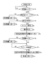
ついで、図10に示すフローチャートを参照して、本実施の形態にかかる電気炊飯器の深夜料金時間帯炊き上げコース制御について説明する。この場合、モード選択キー72iのON操作により深夜料金時間帯炊き上げコースが選択されている。 Next, with reference to the flowchart shown in FIG. 10, midnight charge time zone cooking course control of the electric rice cooker according to the present embodiment will be described. In this case, the midnight charge time zone cooking course is selected by the ON operation of the mode selection key 72i.
ステップS1において予約キー72bによって炊き上げ時刻をAM6:00に設定され、ステップS2において炊飯開始が確認されると、ステップS3においてAM6:00までに炊飯終了させる処理が実行される。そして、ステップS4において時刻がAM6:00になったことが確認されると、ステップS5において保温開始の処理が実行される。ついで、ステップS6において時刻がAM9:30になったことが確認されると、ステップS7において高温保温温度まで昇温させる処理が実行される。その後、ステップS8において時刻がAM10:00になったことが確認されると、ステップS9において保温終了の処理が実行される。 In step S1, the cooking time is set to AM 6:00 by the reservation key 72b, and when the start of rice cooking is confirmed in step S2, the process of finishing rice cooking by AM 6:00 in step S3 is executed. Then, when it is confirmed in step S4 that the time has reached AM 6:00, a heat retention start process is executed in step S5. Next, when it is confirmed in step S6 that the time is AM9: 30, a process of raising the temperature to the high temperature holding temperature is executed in step S7. Thereafter, when it is confirmed in step S8 that the time has reached AM 10:00, a heat retention end process is executed in step S9.
上記したように、深夜料金時間帯炊き上げコース制御においては、AM10:00以降は通常料金より高くなるため、炊飯から保温までの工程をAM10:00までに終わらせるようにしているのである。また、朝食(炊きたて)と昼(保温)の2食は暖かいご飯が食べられるように、AM10:00直前に保温温度を上げて終了させるようにしているのである。 As described above, in the late-night charge time zone cooking course control, after AM 10:00, it becomes higher than the normal charge, so the process from rice cooking to heat insulation is finished by AM 10:00. In addition, the two meals, breakfast (freshly cooked) and lunch (heated), are terminated by raising the temperature before AM10: 00 so that warm rice can be eaten.
上記のようにしたことにより、低料金プランにおける低料金時間帯終了前に大きな消費電力を必要とするモードに入り、通常料金時間帯および高料金時間帯においてはその状態を維持するように制御し得ることとなり、家庭での電力使用料金のさらなる低減を図ることができる。 As a result of the above, it is controlled to enter a mode that requires a large amount of power consumption before the end of the low charge period in the low charge plan, and to maintain the state in the normal charge time period and the high charge time period. As a result, it is possible to further reduce the electricity usage fee at home.
本願発明は、上記実施の形態に限定されるものではなく、発明の要旨を逸脱しない範囲において適宜設計変更可能なことは勿論である。 The invention of the present application is not limited to the above-described embodiment, and it is needless to say that the design can be appropriately changed without departing from the gist of the invention.
4は加熱手段(電気ヒータ)
3は内容器
35は深夜電力モードスイッチ
36は表示手段(液晶表示装置)
43はマイコン基板
71は表示手段(液晶表示装置)
72bは予約キー
82はマイコン
C1,C2,C3は加熱手段(IHコイル)
4 is a heating means (electric heater)
3 is an
43 is a
Claims (5)
Priority Applications (1)
| Application Number | Priority Date | Filing Date | Title |
|---|---|---|---|
| JP2008020504A JP2009178362A (en) | 2008-01-31 | 2008-01-31 | Cooking apparatus |
Applications Claiming Priority (1)
| Application Number | Priority Date | Filing Date | Title |
|---|---|---|---|
| JP2008020504A JP2009178362A (en) | 2008-01-31 | 2008-01-31 | Cooking apparatus |
Publications (1)
| Publication Number | Publication Date |
|---|---|
| JP2009178362A true JP2009178362A (en) | 2009-08-13 |
Family
ID=41032803
Family Applications (1)
| Application Number | Title | Priority Date | Filing Date |
|---|---|---|---|
| JP2008020504A Pending JP2009178362A (en) | 2008-01-31 | 2008-01-31 | Cooking apparatus |
Country Status (1)
| Country | Link |
|---|---|
| JP (1) | JP2009178362A (en) |
Cited By (3)
| Publication number | Priority date | Publication date | Assignee | Title |
|---|---|---|---|---|
| JP2014020773A (en) * | 2012-07-24 | 2014-02-03 | Mitsubishi Electric Corp | Heating cooker and control method for the same and power control system for household electrical appliances |
| US8983672B2 (en) | 2010-03-02 | 2015-03-17 | Samsung Electronics Co., Ltd. | Demand response system |
| WO2020248544A1 (en) * | 2019-06-12 | 2020-12-17 | 佛山市顺德区美的电热电器制造有限公司 | Method and device for cooking scheduling, and storage medium |
Citations (5)
| Publication number | Priority date | Publication date | Assignee | Title |
|---|---|---|---|---|
| JPH06153394A (en) * | 1992-11-06 | 1994-05-31 | Sharp Corp | Electric appliance |
| JP2002033164A (en) * | 2000-05-09 | 2002-01-31 | Sekisui Chem Co Ltd | Plug socket and solar power generating device |
| JP2004332998A (en) * | 2003-05-06 | 2004-11-25 | Corona Corp | Controller of hot water storage type water heater |
| JP2005172579A (en) * | 2003-12-10 | 2005-06-30 | Tokyo Electric Power Co Inc:The | Electronic energy meter |
| JP2005319026A (en) * | 2004-05-07 | 2005-11-17 | Tiger Vacuum Bottle Co Ltd | Electric kettle |
-
2008
- 2008-01-31 JP JP2008020504A patent/JP2009178362A/en active Pending
Patent Citations (5)
| Publication number | Priority date | Publication date | Assignee | Title |
|---|---|---|---|---|
| JPH06153394A (en) * | 1992-11-06 | 1994-05-31 | Sharp Corp | Electric appliance |
| JP2002033164A (en) * | 2000-05-09 | 2002-01-31 | Sekisui Chem Co Ltd | Plug socket and solar power generating device |
| JP2004332998A (en) * | 2003-05-06 | 2004-11-25 | Corona Corp | Controller of hot water storage type water heater |
| JP2005172579A (en) * | 2003-12-10 | 2005-06-30 | Tokyo Electric Power Co Inc:The | Electronic energy meter |
| JP2005319026A (en) * | 2004-05-07 | 2005-11-17 | Tiger Vacuum Bottle Co Ltd | Electric kettle |
Cited By (3)
| Publication number | Priority date | Publication date | Assignee | Title |
|---|---|---|---|---|
| US8983672B2 (en) | 2010-03-02 | 2015-03-17 | Samsung Electronics Co., Ltd. | Demand response system |
| JP2014020773A (en) * | 2012-07-24 | 2014-02-03 | Mitsubishi Electric Corp | Heating cooker and control method for the same and power control system for household electrical appliances |
| WO2020248544A1 (en) * | 2019-06-12 | 2020-12-17 | 佛山市顺德区美的电热电器制造有限公司 | Method and device for cooking scheduling, and storage medium |
Similar Documents
| Publication | Publication Date | Title |
|---|---|---|
| JP3108956B2 (en) | Induction heating cooker | |
| JP5854890B2 (en) | Home appliance power control system | |
| JP2010104669A (en) | Cooking apparatus | |
| JP5863452B2 (en) | Induction heating cooker | |
| JP2009178362A (en) | Cooking apparatus | |
| JP2016112182A (en) | Electric rice cooker | |
| JP3709844B2 (en) | rice cooker | |
| JP4910441B2 (en) | Electric rice cooker | |
| JP5040155B2 (en) | Electric rice cooker | |
| JP2008054916A (en) | Electric rice cooker | |
| JPH10165304A (en) | Pressure cooker | |
| JP4151668B2 (en) | Electric rice cooker | |
| JP5338942B2 (en) | Electric rice cooker | |
| JP2848280B2 (en) | Electromagnetic cooker | |
| JP4923286B2 (en) | Electric rice cooker | |
| JP2002345640A (en) | Cooking tool | |
| JPH04338414A (en) | Rice cooking jar | |
| JP2005124728A (en) | Induction heating cooker | |
| JP4066957B2 (en) | Electric rice cooker | |
| JP2010244997A (en) | Induction heating cooker | |
| JP2010135191A (en) | Induction heating cooker | |
| JP2011160960A (en) | Electric rice cooker | |
| JP4466761B2 (en) | Electric rice cooker | |
| JP3977755B2 (en) | Electric rice cooker | |
| JP3745192B2 (en) | Electric rice cooker |
Legal Events
| Date | Code | Title | Description |
|---|---|---|---|
| A621 | Written request for application examination |
Free format text: JAPANESE INTERMEDIATE CODE: A621 Effective date: 20101207 |
|
| RD02 | Notification of acceptance of power of attorney |
Free format text: JAPANESE INTERMEDIATE CODE: A7422 Effective date: 20120106 |
|
| RD02 | Notification of acceptance of power of attorney |
Free format text: JAPANESE INTERMEDIATE CODE: A7422 Effective date: 20120220 |
|
| A977 | Report on retrieval |
Free format text: JAPANESE INTERMEDIATE CODE: A971007 Effective date: 20120611 |
|
| A131 | Notification of reasons for refusal |
Free format text: JAPANESE INTERMEDIATE CODE: A131 Effective date: 20120619 |
|
| A521 | Written amendment |
Free format text: JAPANESE INTERMEDIATE CODE: A523 Effective date: 20120807 |
|
| A131 | Notification of reasons for refusal |
Free format text: JAPANESE INTERMEDIATE CODE: A131 Effective date: 20130213 |
|
| A02 | Decision of refusal |
Free format text: JAPANESE INTERMEDIATE CODE: A02 Effective date: 20130611 |