JP2007121954A - Optical connector - Google Patents
Optical connector Download PDFInfo
- Publication number
- JP2007121954A JP2007121954A JP2005317423A JP2005317423A JP2007121954A JP 2007121954 A JP2007121954 A JP 2007121954A JP 2005317423 A JP2005317423 A JP 2005317423A JP 2005317423 A JP2005317423 A JP 2005317423A JP 2007121954 A JP2007121954 A JP 2007121954A
- Authority
- JP
- Japan
- Prior art keywords
- connector
- plug
- socket
- housing
- latch
- Prior art date
- Legal status (The legal status is an assumption and is not a legal conclusion. Google has not performed a legal analysis and makes no representation as to the accuracy of the status listed.)
- Pending
Links
- 230000003287 optical effect Effects 0.000 title claims abstract description 50
- 239000000463 material Substances 0.000 claims description 6
- 210000000078 claw Anatomy 0.000 abstract description 31
- 239000013307 optical fiber Substances 0.000 description 31
- 125000006850 spacer group Chemical group 0.000 description 17
- 238000005452 bending Methods 0.000 description 8
- 239000004697 Polyetherimide Substances 0.000 description 4
- 230000005489 elastic deformation Effects 0.000 description 4
- 239000000835 fiber Substances 0.000 description 4
- 230000002093 peripheral effect Effects 0.000 description 4
- 229920001601 polyetherimide Polymers 0.000 description 4
- 239000011347 resin Substances 0.000 description 3
- 229920005989 resin Polymers 0.000 description 3
- 239000004743 Polypropylene Substances 0.000 description 2
- 230000005540 biological transmission Effects 0.000 description 2
- 229920001707 polybutylene terephthalate Polymers 0.000 description 2
- -1 polypropylene Polymers 0.000 description 2
- 229920001155 polypropylene Polymers 0.000 description 2
- 230000002265 prevention Effects 0.000 description 2
- 229920012266 Poly(ether sulfone) PES Polymers 0.000 description 1
- 239000004695 Polyether sulfone Substances 0.000 description 1
- 239000004721 Polyphenylene oxide Substances 0.000 description 1
- 230000002411 adverse Effects 0.000 description 1
- 230000008878 coupling Effects 0.000 description 1
- 238000010168 coupling process Methods 0.000 description 1
- 238000005859 coupling reaction Methods 0.000 description 1
- 230000037431 insertion Effects 0.000 description 1
- 238000003780 insertion Methods 0.000 description 1
- 229920000570 polyether Polymers 0.000 description 1
- 229920006393 polyether sulfone Polymers 0.000 description 1
- 150000003457 sulfones Chemical class 0.000 description 1
Images


Landscapes
- Mechanical Coupling Of Light Guides (AREA)
Abstract
【課題】 作業環境の悪い現場等においても、コネクタプラグとコネクタソケットとの係止状態及び係止解除状態を確実に把握することを可能とする光コネクタを提供する。
【解決手段】 光コネクタ1は、コネクタプラグ2と、このコネクタプラグ2に対して着脱自在に結合されるコネクタソケット3とを備えている。コネクタプラグ2のプラグハウジング4には、プラグハウジング2とコネクタソケット3との嵌合状態を保持する1対のラッチ部13が固定されている。各ラッチ部13は、プラグハウジング4の前端部から後方に向かって延びる弾性変形可能なラッチアーム14を有し、このラッチアーム14には、コネクタソケット3に係合する係止爪15が突設されている。各ラッチアーム14は、プラグハウジング4の後方に向かって開くようにプラグハウジング4に対して傾斜して延びている。
【選択図】 図9PROBLEM TO BE SOLVED: To provide an optical connector capable of surely grasping a locked state and a locked state of a connector plug and a connector socket even in a work environment where the working environment is bad.
An optical connector includes a connector plug and a connector socket that is detachably coupled to the connector plug. A pair of latch portions 13 that hold the fitting state of the plug housing 2 and the connector socket 3 are fixed to the plug housing 4 of the connector plug 2. Each latch portion 13 has an elastically deformable latch arm 14 extending rearward from the front end portion of the plug housing 4, and a latching claw 15 that engages with the connector socket 3 projects from the latch arm 14. Has been. Each latch arm 14 extends obliquely with respect to the plug housing 4 so as to open toward the rear of the plug housing 4.
[Selection] Figure 9
Description
本発明は、コネクタプラグとコネクタソケットとを備え、光ファイバ同士を突き合わせて接続する光コネクタに関するものである。 The present invention relates to an optical connector that includes a connector plug and a connector socket and connects optical fibers to each other.
従来の光コネクタとしては、例えば特許文献1に記載されているものが知られている。この文献に記載の光コネクタは、光ファイバを保持するフェルールと、このフェルールを収納する雄側ハウジングと、この雄側ハウジングに突設され、雄側ハウジングの前端から後端に向けて延在するラッチとを備えている。ラッチには、雌側ハウジングと係脱可能に係合する係合部が突設されている。
例えば架空や壁際等といった作業環境の悪い現場においてコネクタ結合を行う場合には、作業者は、ラッチによる雄側ハウジング(コネクタプラグ)と雌側ハウジング(コネクタソケット)との係止状態及び係止解除状態を正確に知ることが困難となり、作業が行いにくくなる可能性がある。 For example, when connector connection is performed at a site where the working environment is poor, such as aerial or near the wall, the operator can lock and release the locking of the male housing (connector plug) and the female housing (connector socket) by the latch. It may be difficult to know the state accurately and work may be difficult.
本発明の目的は、作業環境の悪い現場等においても、コネクタプラグとコネクタソケットとの係止状態及び係止解除状態を確実に把握することを可能とする光コネクタを提供することである。 An object of the present invention is to provide an optical connector capable of reliably grasping a locked state and a locked state between a connector plug and a connector socket even in a site where the working environment is poor.
本発明は、コネクタプラグと、コネクタプラグに対して着脱自在に結合されるコネクタソケットとを備えた光コネクタにおいて、コネクタプラグは、コネクタソケットと嵌合するプラグハウジングと、プラグハウジングとコネクタソケットとの嵌合状態を保持する1対のラッチ部とを有し、各ラッチ部は、プラグハウジングの後方に向かって延びるようにプラグハウジングの側面に固定され、弾性変形可能なラッチアームと、ラッチアームに突設され、コネクタソケットに係合する係止爪と、ラッチアームの先端に設けられ、コネクタソケットに対する係止爪の係合を解除するためのツマミとを有し、各ラッチ部のラッチアームは、プラグハウジングの後方に向かって開くようにプラグハウジングに対して傾斜して延びていることを特徴とするものである。 The present invention provides an optical connector including a connector plug and a connector socket that is detachably coupled to the connector plug. The connector plug includes a plug housing that fits into the connector socket, a plug housing, and a connector socket. A pair of latch portions for holding the fitting state, each latch portion being fixed to the side surface of the plug housing so as to extend toward the rear of the plug housing, and an elastically deformable latch arm, and a latch arm A latching claw that protrudes and engages with the connector socket, and a knob that is provided at the tip of the latch arm and releases the engagement of the latching claw with respect to the connector socket. The plug housing is inclined and extends so as to open toward the rear of the plug housing. It is intended.
このような光コネクタにおいて、コネクタプラグとコネクタソケットとを結合するときには、コネクタプラグをコネクタソケット内に挿入して、コネクタプラグのプラグハウジングをコネクタソケットに対して嵌合させる。このとき、コネクタプラグをコネクタソケット内に押し込むと、1対のラッチ部がコネクタソケットの内壁面に当たることでプラグハウジング側に弾性変形する。そして、その状態で、更にコネクタプラグを所定位置まで押し込むと、各ラッチ部の弾性力によって各ラッチ部の係止爪がコネクタソケットに係合するようになり、コネクタプラグがコネクタソケットに対して係止された状態となる。一方、コネクタプラグとコネクタソケットとの結合を外すときは、各ラッチ部のツマミをプラグハウジング側に押し込んで、コネクタソケットに対する係止爪の係合を解除することにより、コネクタプラグとコネクタソケットとの係止状態を解除する。そして、その状態で、コネクタプラグをコネクタソケット内から引き抜く。 In such an optical connector, when connecting the connector plug and the connector socket, the connector plug is inserted into the connector socket, and the plug housing of the connector plug is fitted to the connector socket. At this time, when the connector plug is pushed into the connector socket, the pair of latch portions come into contact with the inner wall surface of the connector socket and elastically deform toward the plug housing. In this state, when the connector plug is further pushed into a predetermined position, the latching claw of each latch portion is engaged with the connector socket by the elastic force of each latch portion, and the connector plug is engaged with the connector socket. It will be stopped. On the other hand, when disconnecting the connector plug and the connector socket, the knob of each latch part is pushed into the plug housing side to release the engagement of the locking claw with respect to the connector socket. Release the locked state. In this state, the connector plug is pulled out from the connector socket.
ここで、1対のラッチ部のラッチアームは、プラグハウジングの後方に向かって開くようにプラグハウジングに対して傾斜して延びている。このため、ラッチ部の初期状態では、ラッチアームがプラグハウジングに対して平行に延びている場合に比べて、係止爪の突設位置においてラッチアームとプラグハウジングとの間隔が長くなるため、その分だけラッチアームの弾性変形量が増大する。従って、ラッチ部の弾性力により係止爪がコネクタソケットに係合するときには、係止爪は大きなクリック音を発するようになる。また、コネクタソケットに対する係止爪の係合が解除されるときにも、同様にラッチアームの弾性変形量が増大するため、係止爪は大きなクリック音を発する。このように見た目だけでなく、音によってもコネクタプラグとコネクタソケットとの係止状態及び係止解除状態がはっきり分かるようになる。これにより、作業環境のあまり良くない現場等においても、作業者は、コネクタプラグとコネクタソケットとの係止状態及び係止解除状態を正確に知ることが可能となる。 Here, the latch arms of the pair of latch portions extend obliquely with respect to the plug housing so as to open toward the rear of the plug housing. For this reason, in the initial state of the latch portion, the interval between the latch arm and the plug housing becomes longer at the protruding position of the latching claw than when the latch arm extends parallel to the plug housing. The amount of elastic deformation of the latch arm increases by that amount. Therefore, when the latching claw is engaged with the connector socket by the elastic force of the latch portion, the latching claw emits a loud click sound. Also, when the engagement of the locking claw with the connector socket is released, the amount of elastic deformation of the latch arm similarly increases, so that the locking claw makes a loud clicking sound. Thus, not only the appearance but also the sound makes it possible to clearly understand the locked state and the unlocked state of the connector plug and the connector socket. Thereby, even in a site where the working environment is not so good, the worker can accurately know the locked state and the locked state of the connector plug and the connector socket.
好ましくは、ツマミの内側の面は、プラグハウジングに対してラッチアームの傾斜角度よりも大きい傾斜角度で開くように構成されている。この場合には、ツマミとプラグハウジングとの間隔が長くなるため、ツマミをプラグハウジングに押し付けた時のラッチアームの弾性変形量が更に増大する。これにより、コネクタソケットに対する係止爪の係合が解除されるときに、係止爪は一層大きなクリック音を発するようになる。 Preferably, the inner surface of the knob is configured to open with respect to the plug housing at an inclination angle larger than the inclination angle of the latch arm. In this case, since the distance between the knob and the plug housing becomes long, the amount of elastic deformation of the latch arm when the knob is pressed against the plug housing further increases. Thereby, when the engagement of the locking claw with respect to the connector socket is released, the locking claw emits a larger click sound.
また、好ましくは、各ラッチ部は、耐クリープ性を有する材料で形成されている。この場合には、例えばラッチ部に何らかの応力がかかった状態でも、ラッチ部に歪みが発生しにくくなり、コネクタプラグをコネクタソケットに対してスムーズに係止(ラッチ)させることができる。なお、耐クリープ性を有する材料としては、ポリエーテルイミド(PEI)やポリエーテルスルホン(PES)等が挙げられる。 Preferably, each latch portion is formed of a material having creep resistance. In this case, for example, even when some stress is applied to the latch portion, the latch portion is less likely to be distorted, and the connector plug can be smoothly locked (latched) to the connector socket. Examples of the material having creep resistance include polyetherimide (PEI) and polyethersulfone (PES).
本発明によれば、例えば架空や壁際といった作業環境の悪い現場等においても、コネクタプラグとコネクタソケットとの係止状態及び係止解除状態を確実に把握し、作業性を向上させることが可能となる。 According to the present invention, it is possible to reliably grasp the engagement state and the engagement release state between the connector plug and the connector socket, and improve workability even in a site where the working environment is poor, such as an aerial or a wall. Become.
以下、本発明に係る光コネクタの好適な実施形態について図面を参照して詳細に説明する。 DESCRIPTION OF EMBODIMENTS Hereinafter, preferred embodiments of an optical connector according to the present invention will be described in detail with reference to the drawings.
図1は、本発明に係る光コネクタの一実施形態を示す斜視図である。同図において、本実施形態の光コネクタ1は、コネクタプラグ2と、このコネクタプラグ2に対して着脱自在に結合されるコネクタソケット3とを備えている。コネクタプラグ2及びコネクタソケット3は、何れもコード把持タイプである。
FIG. 1 is a perspective view showing an embodiment of an optical connector according to the present invention. In the figure, an optical connector 1 according to this embodiment includes a
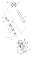
図2はコネクタプラグ2の分解斜視図であり、図3はコネクタプラグ2の水平方向断面図であり、図4はコネクタプラグ2の垂直方向断面図(図3のIV−IV線断面図)である。
2 is an exploded perspective view of the
各図において、コネクタプラグ2は、断面略矩形状のプラグハウジング4を有している。このプラグハウジング4内には、プラグハウジング4の前端面(結合端面)側から後端側に向けてフェルール5、スペーサ6、ストップリング7、カシメリング8が順に配置されている。また、プラグハウジング4内には、光ファイバ9aが内蔵された光コード9を導入するブーツ10がプラグハウジング4の後端側から挿入されている。
In each figure, the
フェルール5は、略円柱状を有し、プラグハウジング4の後端側から導入された光コード9の光ファイバ9aの先端部を保持する。スペーサ6は、フェルール5とストップリング7との間隔を規定(調整)するリング状の部材である。スペーサ6の一端部には、環状突部6aが設けられている。そして、フェルール5の後端側部分は、環状突部6a側からスペーサ6に挿入されている。
The
ストップリング7は、その外周面に設けられた係止部7aによってプラグハウジング4に固定されている。また、ストップリング7の外周面には、ブーツ10に形成された係止部10aと係合する環状溝7bが形成されている。
The
ストップリング7の後端側部分は、カシメリング8に挿入されている。ストップリング7とカシメリング8との間には、光コード9の外被から露出されたケプラー9bが挟み込まれており、その状態でカシメリング8がストップリング7に対してかしめられている。カシメリング8は、リング11を介してブーツ10内に収容されている。
A rear end side portion of the
また、プラグハウジング4の後端部には、ブーツ10の曲げを抑えるための2枚の曲げ止めプレート12がブーツ10を挟み込むように左右両側に取り付けられている。このような曲げ止めプレート12を設けることにより、ブーツ10がプラグハウジング4に対して左右方向に拘束されることになるため、曲げに対するブーツ10の強度が高くなり、光コード9に与える影響を軽減することができる。
Further, at the rear end of the
プラグハウジング4の対向する2つの側面4aには、プラグハウジング2とコネクタソケット3との嵌合状態を保持する1対のラッチ部13が一体的に設けられている。各ラッチ部13は、プラグハウジング4の前端部から後端側に向かって延びるようにプラグハウジング4の側面4aに固定されたラッチアーム14を有している。このラッチアーム14は、プラグハウジング4の幅方向に弾性変形可能である。ラッチアーム14の外側の面(プラグハウジング4とは反対側の面)には、コネクタソケット3に係合する係止爪15が突設されている。また、ラッチアーム14の先端には、コネクタソケット3に対する係止爪15の係合を解除するためのツマミ16が設けられている。
A pair of
各ラッチ部13のラッチアーム14は、プラグハウジング4の後端側に向かって開くようにプラグハウジング4の側面4aに対して傾斜して延びている。また、ツマミ16の内側の面(プラグハウジング4側の面)は、プラグハウジング4の側面4aに対してラッチアーム14の傾斜角度よりも大きい傾斜角度で開くように構成されているのが好ましい。具体的には、プラグハウジング4の側面4aに対するラッチアーム14の傾斜角度α(図5参照)は、例えば2〜3度である。また、プラグハウジング4の側面4aに対するツマミ16の内側の面の傾斜角度β(図5参照)は、例えば8〜12度である。
The
プラグハウジング4及びラッチ部13は、低コスト化の観点から、1つの成形部品として一体成形するのが望ましい。プラグハウジング4及びラッチ部13を形成する樹脂材料としては、精密成形が可能であり且つ耐熱性や信頼性に優れ、更には耐クリープ性を有するという点から、ポリエーテルイミド(PEI)やポリエーテルスルホン(PES)等を使用するのが好ましい。これにより、光コネクタ1を屋外環境下で使用する際に、例えばラッチ部13に応力がかかっても、ラッチ部13の歪みが生じにくくなるため、プラグハウジング4とコネクタソケット3とのラッチ動作を損なうことは殆ど無い。
The
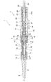
図6はコネクタソケット3の分解斜視図であり、図7はコネクタソケット3の水平方向断面図であり、図8はコネクタソケット3の垂直方向断面図(図7のVIII−VIII線断面図)である。
6 is an exploded perspective view of the
各図において、コネクタソケット3は、コネクタプラグ2のプラグハウジング4と嵌合する断面略矩形状のソケットハウジング17を有している。ソケットハウジング17の対向する2つの側面17aには、ラッチ部13の係止爪15と係合する係止受け用窓部18がそれぞれ設けられている。なお、ソケットハウジング17を形成する樹脂材料は、例えばコネクタプラグ2のプラグハウジング4及びラッチ部13を形成する樹脂材料と同様である。
In each figure, the
ソケットハウジング17内には、ソケットハウジング17の前端面(結合端面)側から後端側に向けて割スリーブ19、フェルール20、スペーサ21、ストップリング22、カシメリング23が順に配置されている。また、ソケットハウジング17内には、光ファイバ24aが内蔵された光コード24を導入するブーツ25がソケットハウジング17の後端側から挿入されている。
In the
フェルール20は、例えばフェルール5と同じ構造を有し、ソケットハウジング17の後端側からソケットハウジング17内に導入された光コード24の光ファイバ24aの先端部を保持する。割スリーブ19の後端側部分には、フェルール20の前端側部分が挿入されている。割スリーブ19の前端側部分には、コネクタプラグ2とコネクタソケット3との結合時にフェルール5の前端側部分が挿入される。割スリーブ19は、スリーブストッパ26によりソケットハウジング17に固定されている。
The
スペーサ21は、フェルール20とストップリング22との間隔を規定(調整)するリング状の部材である。スペーサ21は、コネクタプラグ2のスペーサ6と同じ構造を有している。つまり、スペーサ21の一端部には、環状突部21aが設けられている。そして、フェルール20の後端側部分は、環状突部21aの反対側からスペーサ21に挿入されている。これにより、フェルール20の前端面に対するスペーサ21の配置方向は、フェルール5の前端面に対するスペーサ6の配置方向と逆になる。このようにスペーサ7,21を同じ構造とすることにより、フェルール5とストップリング7との間隔調整と、フェルール20とストップリング22との間隔調整とを、1種類のスペーサだけを用いて行うことができ、コスト的に有利となる。また、スペーサ21内には、フェルール20側に付勢するバネ27が配置されている。
The
スペーサ21の環状突部21aには、ストップリング22の前端部が嵌り込んでいる。ストップリング22は、コネクタプラグ2のストップリング7と同じ構造を有している。つまり、ストップリング22は、その外周面に設けられた係止部22aによってソケットハウジング17に固定されている。また、ストップリング22の外周面には、ブーツ25に形成された係止部25aと係合する環状溝22bが形成されている。
The front end of the
ストップリング22の後端側部分は、カシメリング23に挿入されている。ストップリング22とカシメリング23との間には、光コード24の外被から露出されたケプラー24bが挟み込まれており、その状態でカシメリング23がストップリング22に対してかしめられている。このカシメリング23は、リング28を介してブーツ25内に収容されている。
A rear end side portion of the
また、ソケットハウジング17の後端部には、ブーツ25の曲げを抑えるための2枚の曲げ止めプレート29がブーツ25を挟み込むように上下に取り付けられている。曲げ止めプレート29は、コネクタプラグ2の曲げ止めプレート12と全く同じ構造を有している。このような曲げ止めプレート29を設けることにより、ブーツ25がソケットハウジング17に対して上下方向に拘束されるため、曲げに対するブーツ25の強度が高くなり、光コード24に与える影響を軽減することができる。
Further, at the rear end of the
以上のように構成されたコネクタプラグ2とソケットハウジング3とを結合させる場合には、図9に示すように、コネクタプラグ2の前端面とコネクタソケット3の前端面とを対向させる。そして、図10に示すように、コネクタソケット3の割スリーブ19内にコネクタプラグ2のフェルール5が差し込まれるように、コネクタプラグ2をコネクタソケット3内に挿入して押し込んでいく。このとき、ラッチ部13がソケットハウジング17の内壁面に当接することで、ラッチ部13の付勢力に抗してラッチ部13がプラグハウジング4側に弾性変形した状態となる。
When the
その状態で、コネクタプラグ2を更に押し込んでいくと、ラッチ部13の係止爪15がソケットハウジング17の係止受け用窓部18の位置に達する。すると、ラッチ部13の付勢力によってラッチ部13が初期状態に戻ろうとしてプラグハウジング4の外側に広がるため、図11に示すように、係止受け用窓部18に係止爪15が引っ掛かるようになる。これにより、コネクタプラグ2とコネクタソケット3とが係止された状態となる。この状態では、フェルール20にフェルール5が突き当たり、光ファイバ9a,24a同士が光接続される。
In this state, when the
ここで、コネクタソケット3のフェルール20とスペーサ21との間には、フェルール20側に付勢するバネ27が介在されているので、フェルール5がフェルール20に突き当たったときには、バネ27の付勢力に抗してフェルール20が僅かに後退する。しかし、光コード24の内部には、光ファイバ24aを多少撓ませることができる程度の僅かな空間が存在している。このため、光コード24の外被から露出した光ファイバ24aがソケットハウジング17内で急激に撓むことは無いので、光ファイバ24aの伝送特性に悪影響を及ぼすことは殆ど無い。
Here, since the
一方、コネクタプラグ2とコネクタソケット3との結合を外す場合には、各ラッチ部13のツマミ16をプラグハウジング4の側面4aに突き当たるように掴んで、ソケットハウジング17の係止受け用窓部18に対する係止爪15の係合を解除する。これにより、コネクタプラグ2とコネクタソケット3との係止状態が解除されるようになる。そして、その状態で、両方のツマミ16を掴んだまま、コネクタプラグ2をコネクタソケット3から引き抜く。
On the other hand, when the connection between the
ここで、各ラッチ部13のラッチアーム14は、プラグハウジング4の後方に向かって開くようにプラグハウジング4の側面4aに対して所定の角度αで傾斜している。しかも、各ツマミ16の内側の面は、プラグハウジング4の側面4aに対してラッチアーム14の傾斜角度αよりも大きい角度βで開くように構成されている。このため、各ラッチ部13が弾性変形していない初期状態では、ラッチアーム14がプラグハウジング4の側面4aに対して平行に延びている場合に比べて、ラッチアーム14における係止爪15に対する部位とプラグハウジング4とのクリアランスが大きくなるため、その分だけラッチアーム14の弾性変形量が増大することになる。
Here, the
これにより、ラッチアーム14の付勢力により係止爪15が係止受け用窓部18に引っ掛かるときに、ソケットハウジング17に係止爪15が勢い良く当たることで発する「カチッ」というクリック音の音量が大きくなる。また、係止受け用窓部18への係止爪15の引っ掛かりが解除されるときに、ソケットハウジング17から係止爪15が勢い良く離れることで発する「カチッ」というクリック音の音量も大きくなる。
Thereby, when the latching
このようにコネクタプラグ2とコネクタソケット3とが係止されたか否か、コネクタプラグ2とコネクタソケット3との係止状態が解除されたか否かを、見た目だけでなく、クリック音でもはっきり分かるようになる。架空や壁際等といった作業環境の悪い現場において作業を行う場合には、光コネクタ1の結合状態が良く見えないこともあり得る。しかし、このような場合でも、作業者は、大きなクリック音によってコネクタプラグ2とコネクタソケット3との係止状態及び係止解除状態を正確に知ることができるので、作業性を向上させることが可能となる。
Thus, whether the
図12は、本発明に係る光コネクタの他の実施形態を示す斜視図である。図中、上述した実施形態と同一または同等の部材には同じ符号を付し、その説明を省略する。 FIG. 12 is a perspective view showing another embodiment of the optical connector according to the present invention. In the drawing, the same reference numerals are given to the same or equivalent members as those of the above-described embodiment, and the description thereof is omitted.
同図において、本実施形態の光コネクタ40は、コネクタプラグ41と、このコネクタプラグ41に対して着脱自在に結合されるコネクタソケット42とを備えている。コネクタプラグ41及びコネクタソケット42は、何れも心線把持タイプである。
In the figure, an
図13はコネクタプラグ41の分解斜視図であり、図14はコネクタプラグ42の水平方向断面図であり、図15はコネクタプラグ42の垂直方向断面図(図14のXV−XV線断面図)である。各図において、コネクタプラグ41は、上述した実施形態と同様に、プラグハウジング4及び1対のラッチ部13を有している。
13 is an exploded perspective view of the
プラグハウジング4内には、メカニカルスプライス43及びストッパ44が配置されている。メカニカルスプライス43は、ベース部及びカバー部からなるスプライス部材45と、このスプライス部材45をクランプする2つのクランプ部材46とを有し、プラグハウジング4の後端側からプラグハウジング4内に導入された光ファイバ47の先端部を保持する。スプライス部材45の前端側部分には、光ファイバ47と接続される短尺ファイバ48が内蔵されている。
A
また、メカニカルスプライス43には、クランプ部材46の押圧力に抗してスプライス部材45のベース部とカバー部とを押し開くための楔(図示せず)が挿入される2つのスリット49が形成されている。そして、プラグハウジング4における各スリット49に対応する位置には、楔が挿入される2つの楔窓50が形成されている。
The
ストッパ44は、プラグハウジング4の後部に配置され、円筒状部51を有している。ストッパ44は、円筒状部51に設けられた係止部51aによってプラグハウジング4に固定されている。
The
図16はコネクタソケット42の分解斜視図であり、図17はコネクタソケット42の水平方向断面図であり、図18はコネクタソケット42の垂直方向断面図(図17のXVIII−XVIII線断面図)である。各図において、コネクタソケット42は、上述した実施形態と同様にソケットハウジング17を有している。ソケットハウジング17内には、ソケットハウジング17の前端面側から後端側に向けて割スリーブ53、メカニカルスプライス54、ストッパ55が順に配置されている。
16 is an exploded perspective view of the
メカニカルスプライス54は、ベース部及びカバー部からなるスプライス部材56と、このスプライス部材56をクランプする2つのクランプ部材57とを有し、ソケットハウジング17の後端側からソケットハウジング17内に導入された光ファイバ58の先端部を保持する。メカニカルスプライス54の前端側部分には、光ファイバ58と接続される短尺ファイバ59が内蔵されている。また、メカニカルスプライス54には、上記の楔(図示せず)が挿入される2つのスリット60が形成されている。そして、ソケットハウジング17における各スリット60に対応する位置には、楔が挿入される2つの楔窓61が形成されている。
The
割スリーブ53の後端側には、スプライス部材56の前端側部分(フェルール部)56aが挿入されている。割スリーブ53の前端側には、コネクタプラグ41とコネクタソケット42との結合時にスプライス部材45の前端側部分(フェルール部)45aが挿入される。割スリーブ53は、スルーブストッパ62によりソケットハウジング17に固定されている。
A front end side portion (ferrule portion) 56 a of the
ストッパ55は、ソケットハウジング17の後部に配置され、円筒状部63を有している。ストッパ55は、円筒状部63に設けられた係止部63aによってソケットハウジング17に固定されている。また、円筒状部63内には、メカニカルスプライス54側に付勢するバネ65が配置されている。
The
以上のような光コネクタ40において、コネクタプラグ41とコネクタソケット42とを結合させるときは、図19に示すようにコネクタプラグ41をコネクタソケット42内に挿入して押し込んでいく。このとき、各ラッチ部13の係止爪15がソケットハウジング17の係止受け用窓部18の位置に達すると、係止爪15が係止受け用窓部18に引っ掛かり、コネクタプラグ41とコネクタソケット42とが係止状態となる。一方、各ラッチ部13のツマミ16を押し込んで、ソケットハウジング17に対する係止爪15の係合を解除すると、コネクタプラグ41とコネクタソケット42とが係止解除状態となる。
In the
このような本実施形態においても、各ラッチ部13の初期状態では、ラッチアーム14がプラグハウジング4の後方に向かって開いているので、係止爪15が発する大きなクリック音によって、作業者はコネクタプラグ41とコネクタソケット42との係止状態及び係止解除状態を正確に知ることができる。
Also in this embodiment, since the
図20は、本発明に係る光コネクタの更に他の実施形態を示す斜視図である。図中、上述した実施形態と同一または同等の部材には同じ符号を付し、その説明を省略する。 FIG. 20 is a perspective view showing still another embodiment of the optical connector according to the present invention. In the drawing, the same reference numerals are given to the same or equivalent members as those of the above-described embodiment, and the description thereof is omitted.
同図において、本実施形態の光コネクタ70は、外被把持型のコネクタプラグ71と、このコネクタプラグ71に対して着脱自在に結合される心線把持タイプのコネクタソケット42とを備えている。
In the figure, an
図21はコネクタプラグ71の分解斜視図であり、図22はコネクタプラグ71の水平方向断面図であり、図23はコネクタプラグ71の垂直方向断面図(図22のXXIII−XXIII線断面図)である。各図において、コネクタプラグ71は、コネクタソケット17と嵌合する断面略矩形状のプラグハウジング72と、このプラグハウジング72に対して開閉可能なカバー73とを有している。プラグハウジング72の対向する2つの側面72aの前端部には、ラッチ部13がそれぞれ一体的に設けられている。
21 is an exploded perspective view of the
カバー73は、図21及び図24に示すように、プラグハウジング72の両側面72aに突設された軸部74を介して回動自在に支持され、閉じた状態においてプラグハウジング72の後部を覆うように構成されている。
As shown in FIGS. 21 and 24, the
プラグハウジング72内には、プラグハウジング72の前端面側から後端側に向けてメカニカルスプライス75、ストッパ76、ケーブルホルダ77が順に配置されている。メカニカルスプライス75は、上述したコネクタプラグ41のメカニカルスプライス43と同じ構造を有し、プラグハウジング72の後端側からプラグハウジング72内に導入された光ケーブル78の光ファイバ79の先端部を保持する。プラグハウジング72のスプライス部材45の前端側部分には、光ファイバ79と接続される短尺ファイバ80が内蔵されている。なお、プラグハウジング72におけるメカニカルスプライス75の各スリット49に対応する位置には、上記の楔(図示せず)が挿入される2つの楔窓81が形成されている。
In the
ストッパ76は、その両側面に設けられた係止突部76aによってプラグハウジング72に固定されている。また、ストッパ76の後端部には、ストッパ76の幅方向に弾性変形可能な1対の突出部82が設けられ、各突出部82には開口82aが形成されている。なお、開口82aの代わりに凹部を形成しても良い。
The
ケーブルホルダ77は、光ケーブル78を挿通させた状態で光ケーブル78の外被を把持する部材であり、ポリプロピレン(PP)やポリブチレンテレフタレート(PBT)等で形成されている。光ケーブル78としては、例えば1本の光ファイバ79と2本のテンションメンバ(図示せず)とを外被で被覆してなるものが使用される。ケーブルホルダ77の両側面には、ストッパ76の各突出部82に形成された開口82aに嵌合する凸部77aが設けられている。
The
このようなコネクタプラグ71に光ケーブル78を組み付ける場合には、図25に示すように、ケーブルホルダ77が組み込まれていない状態のプラグハウジング72を光ファイバ組付治具83の上に載置する。このとき、コネクタプラグ71のカバー73は、プラグハウジング72に対して開いて立てた状態にしておく。また、光ファイバ組付治具83の楔挿入レバー84によって、メカニカルスプライス75のスプライス部材45を押し開いておく。そして、端末処理が施された状態の光ファイバ79を内蔵した光ケーブル78をケーブルホルダ77により保持した後、そのケーブルホルダ77を光ファイバ組付治具83の上にストッパ76と対向するように載置する。
When the
そして、図26に示すように、ケーブルホルダ77を光ファイバ組付治具83の上面に沿ってプラグハウジング72に向けて摺動させて、メカニカルスプライス75に内蔵された短尺ファイバ80に光ファイバ79が突き当たるように、コネクタプラグ72内にケーブルホルダ77を入れる。
Then, as shown in FIG. 26, the
このとき、図27に示すように、ケーブルホルダ77がストッパ76に対して押し込まれることで、ストッパ76の各突出部82が外側に押し広げられ、各突出部82に形成された開口82aにケーブルホルダ77の凸部77aが嵌まり込むようになる。これにより、ケーブルホルダ77を動かしていた手を離しても、ストッパ76とケーブルホルダ77とが仮固定された状態に維持されるようになる。従って、その後は、片手で光ファイバ組付治具83を持ちながら、その手で楔引き抜きレバー85を操作して、メカニカルスプライス75のスプライス部材45を閉じることが可能となる。
At this time, as shown in FIG. 27, when the
以上のような光コネクタ70において、コネクタプラグ71とコネクタソケット42とを結合させるときは、図28に示すようにコネクタプラグ71をコネクタソケット42内に挿入して押し込んでいく。このとき、各ラッチ部13の係止爪15がソケットハウジング17の係止受け用窓部18の位置に達すると、係止爪15が係止受け用窓部18に引っ掛かり、コネクタプラグ71とコネクタソケット42とが係止状態となる。
In the
ここで、メカニカルスプライス54とストッパ55との間にはバネ65が介在されているので、コネクタソケット42のメカニカルスプライス54にコネクタプラグ71のメカニカルスプライス75が突き当たったときには、バネ65の付勢力に抗してメカニカルスプライス54が僅かに後退する。しかし、コネクタソケット42内には、光コードではなく光ファイバ58が導入されているので、メカニカルスプライス54の後退に伴って光ファイバ58が後退するだけとなる。このため、光ファイバ58がコネクタソケット42内で急激に撓むことは無く、光ファイバ58の伝送特性に支障をきたすことは殆ど無い。
Here, since the
一方、各ラッチ部13のツマミ16を押し込んで、ソケットハウジング17に対する係止爪15の係合を解除すると、コネクタプラグ71とコネクタソケット42とが係止解除状態となる。
On the other hand, when the
このような本実施形態においても、各ラッチ部13の初期状態では、ラッチアーム14がプラグハウジング72の後方に向かって開いているので、係止爪15が発する大きなクリック音によって、作業者はコネクタプラグ71とコネクタソケット42との係止状態及び係止解除状態を正確に知ることができる。
Also in this embodiment, since the
なお、本発明は、上記実施形態に限定されるものではない。例えば、上記実施形態の光コネクタは、単心の光ファイバ同士を接続するものであるが、本発明は、複数心の光ファイバ同士を接続するものにも適用可能である。 The present invention is not limited to the above embodiment. For example, the optical connector of the above embodiment connects single optical fibers, but the present invention can also be applied to an optical fiber connecting multiple optical fibers.
1…光コネクタ、2…コネクタプラグ、3…コネクタソケット、4…プラグハウジング、13…ラッチ部、14…ラッチアーム、15…係止爪、16…ツマミ、40…光コネクタ、41…コネクタプラグ、42…コネクタソケット、70…光コネクタ、71…コネクタプラグ、72…プラグハウジング。 DESCRIPTION OF SYMBOLS 1 ... Optical connector, 2 ... Connector plug, 3 ... Connector socket, 4 ... Plug housing, 13 ... Latch part, 14 ... Latch arm, 15 ... Locking claw, 16 ... Knob, 40 ... Optical connector, 41 ... Connector plug, 42 ... Connector socket, 70 ... Optical connector, 71 ... Connector plug, 72 ... Plug housing.
Claims (3)
前記コネクタプラグは、前記コネクタソケットと嵌合するプラグハウジングと、前記プラグハウジングと前記コネクタソケットとの嵌合状態を保持する1対のラッチ部とを有し、
前記各ラッチ部は、前記プラグハウジングの後方に向かって延びるように前記プラグハウジングの側面に固定され、弾性変形可能なラッチアームと、前記ラッチアームに突設され、前記コネクタソケットに係合する係止爪と、前記ラッチアームの先端に設けられ、前記コネクタソケットに対する前記係止爪の係合を解除するためのツマミとを有し、
前記各ラッチ部の前記ラッチアームは、前記プラグハウジングの後方に向かって開くように前記プラグハウジングに対して傾斜して延びていることを特徴とする光コネクタ。 In an optical connector comprising a connector plug and a connector socket detachably coupled to the connector plug,
The connector plug has a plug housing that fits into the connector socket, and a pair of latch portions that hold the fitting state between the plug housing and the connector socket,
Each of the latch portions is fixed to a side surface of the plug housing so as to extend toward the rear of the plug housing, and an elastically deformable latch arm and a latch projecting from the latch arm and engaging with the connector socket. A pawl, and a knob provided at the tip of the latch arm for releasing the engagement of the locking pawl with respect to the connector socket;
The optical connector according to claim 1, wherein the latch arm of each of the latch portions extends with an inclination to the plug housing so as to open toward the rear of the plug housing.
Priority Applications (1)
| Application Number | Priority Date | Filing Date | Title |
|---|---|---|---|
| JP2005317423A JP2007121954A (en) | 2005-10-31 | 2005-10-31 | Optical connector |
Applications Claiming Priority (1)
| Application Number | Priority Date | Filing Date | Title |
|---|---|---|---|
| JP2005317423A JP2007121954A (en) | 2005-10-31 | 2005-10-31 | Optical connector |
Publications (1)
| Publication Number | Publication Date |
|---|---|
| JP2007121954A true JP2007121954A (en) | 2007-05-17 |
Family
ID=38145831
Family Applications (1)
| Application Number | Title | Priority Date | Filing Date |
|---|---|---|---|
| JP2005317423A Pending JP2007121954A (en) | 2005-10-31 | 2005-10-31 | Optical connector |
Country Status (1)
| Country | Link |
|---|---|
| JP (1) | JP2007121954A (en) |
Cited By (13)
| Publication number | Priority date | Publication date | Assignee | Title |
|---|---|---|---|---|
| JP2007121929A (en) * | 2005-10-31 | 2007-05-17 | Sumitomo Electric Ind Ltd | Optical connector |
| JP2007121843A (en) * | 2005-10-31 | 2007-05-17 | Three M Innovative Properties Co | Optical connector |
| WO2008062741A1 (en) * | 2006-11-24 | 2008-05-29 | Terumo Kabushiki Kaisha | Connector and infusion tube set |
| JP2009104069A (en) * | 2007-10-25 | 2009-05-14 | Sumitomo Electric Ind Ltd | Fixing member for optical connector and mounting method of optical connector |
| CN102301265A (en) * | 2009-02-13 | 2011-12-28 | 株式会社藤仓 | Optical connector and method for assembling optical connector |
| JP2012220797A (en) * | 2011-04-11 | 2012-11-12 | Furukawa Electric Co Ltd:The | Connecting structure of optical connector |
| CN103901554A (en) * | 2014-03-12 | 2014-07-02 | 中航光电科技股份有限公司 | Small high-density multi-core optical fiber connector |
| JP2014186267A (en) * | 2013-03-25 | 2014-10-02 | Furukawa Electric Co Ltd:The | Connector |
| JP2014186274A (en) * | 2013-03-25 | 2014-10-02 | Furukawa Electric Co Ltd:The | Connector |
| JP2014199747A (en) * | 2013-03-29 | 2014-10-23 | 古河電気工業株式会社 | Connector |
| CN107884879A (en) * | 2017-11-10 | 2018-04-06 | 中航光电科技股份有限公司 | A kind of short formula protective cover of the joints of optical fibre |
| TWI728619B (en) * | 2019-12-24 | 2021-05-21 | 立佳興業股份有限公司 | Optical connector and optical module using the same |
| TWI766347B (en) * | 2019-12-24 | 2022-06-01 | 立佳興業股份有限公司 | Optical connector module |
Citations (5)
| Publication number | Priority date | Publication date | Assignee | Title |
|---|---|---|---|---|
| JPH1078534A (en) * | 1996-09-03 | 1998-03-24 | Yazaki Corp | Optical connector |
| JP2000147315A (en) * | 1998-11-16 | 2000-05-26 | Fujikura Ltd | Optical connector |
| JP2000338369A (en) * | 1999-05-12 | 2000-12-08 | Siecor Operations Llc | Detachable optical fiber connector and related |
| JP2001147344A (en) * | 1999-10-06 | 2001-05-29 | Lucent Technol Inc | Optical connector having housing assembly containing polyphenyl sulfone |
| JP2003098381A (en) * | 2001-09-26 | 2003-04-03 | Furukawa Electric Co Ltd:The | Optical connector housing and optical connector |
-
2005
- 2005-10-31 JP JP2005317423A patent/JP2007121954A/en active Pending
Patent Citations (5)
| Publication number | Priority date | Publication date | Assignee | Title |
|---|---|---|---|---|
| JPH1078534A (en) * | 1996-09-03 | 1998-03-24 | Yazaki Corp | Optical connector |
| JP2000147315A (en) * | 1998-11-16 | 2000-05-26 | Fujikura Ltd | Optical connector |
| JP2000338369A (en) * | 1999-05-12 | 2000-12-08 | Siecor Operations Llc | Detachable optical fiber connector and related |
| JP2001147344A (en) * | 1999-10-06 | 2001-05-29 | Lucent Technol Inc | Optical connector having housing assembly containing polyphenyl sulfone |
| JP2003098381A (en) * | 2001-09-26 | 2003-04-03 | Furukawa Electric Co Ltd:The | Optical connector housing and optical connector |
Cited By (19)
| Publication number | Priority date | Publication date | Assignee | Title |
|---|---|---|---|---|
| JP2007121843A (en) * | 2005-10-31 | 2007-05-17 | Three M Innovative Properties Co | Optical connector |
| JP4568208B2 (en) * | 2005-10-31 | 2010-10-27 | 住友電気工業株式会社 | Optical connector |
| JP4660351B2 (en) * | 2005-10-31 | 2011-03-30 | スリーエム イノベイティブ プロパティズ カンパニー | Optical connector |
| JP2007121929A (en) * | 2005-10-31 | 2007-05-17 | Sumitomo Electric Ind Ltd | Optical connector |
| WO2008062741A1 (en) * | 2006-11-24 | 2008-05-29 | Terumo Kabushiki Kaisha | Connector and infusion tube set |
| US8197466B2 (en) | 2006-11-24 | 2012-06-12 | Terumo Kabushiki Kaisha | Connector and infusion tube set |
| JP2009104069A (en) * | 2007-10-25 | 2009-05-14 | Sumitomo Electric Ind Ltd | Fixing member for optical connector and mounting method of optical connector |
| CN102301265B (en) * | 2009-02-13 | 2014-04-16 | 株式会社藤仓 | Optical connector and method for assembling optical connector |
| CN102301265A (en) * | 2009-02-13 | 2011-12-28 | 株式会社藤仓 | Optical connector and method for assembling optical connector |
| JP2012220797A (en) * | 2011-04-11 | 2012-11-12 | Furukawa Electric Co Ltd:The | Connecting structure of optical connector |
| JP2014186267A (en) * | 2013-03-25 | 2014-10-02 | Furukawa Electric Co Ltd:The | Connector |
| JP2014186274A (en) * | 2013-03-25 | 2014-10-02 | Furukawa Electric Co Ltd:The | Connector |
| JP2014199747A (en) * | 2013-03-29 | 2014-10-23 | 古河電気工業株式会社 | Connector |
| CN103901554A (en) * | 2014-03-12 | 2014-07-02 | 中航光电科技股份有限公司 | Small high-density multi-core optical fiber connector |
| CN103901554B (en) * | 2014-03-12 | 2016-03-02 | 中航光电科技股份有限公司 | A kind of Miniature high-density multi-fiber connector |
| CN107884879A (en) * | 2017-11-10 | 2018-04-06 | 中航光电科技股份有限公司 | A kind of short formula protective cover of the joints of optical fibre |
| CN107884879B (en) * | 2017-11-10 | 2019-05-21 | 中航光电科技股份有限公司 | A kind of short formula protective cover of optical fiber connector |
| TWI728619B (en) * | 2019-12-24 | 2021-05-21 | 立佳興業股份有限公司 | Optical connector and optical module using the same |
| TWI766347B (en) * | 2019-12-24 | 2022-06-01 | 立佳興業股份有限公司 | Optical connector module |
Similar Documents
| Publication | Publication Date | Title |
|---|---|---|
| CN101299086B (en) | Optical fibre connector and assembly method thereof | |
| JP4416591B2 (en) | Optical connector and optical fiber connection system | |
| JP2007121954A (en) | Optical connector | |
| JP4482591B2 (en) | Optical connector | |
| US7717623B2 (en) | Optical connector and optical connector assembling method | |
| CN101820118A (en) | Waterproof connector and waterproof device using the waterproof connector | |
| WO2004059512A2 (en) | Optical fiber ferrule assembly and methods of construction | |
| JP5882765B2 (en) | Optical connector | |
| JP2011034001A (en) | Optical connector and optical connector-connecting structure | |
| JP2020046582A (en) | Lc uni-boot plug connector | |
| JP4191168B2 (en) | Mechanical connection type optical connector | |
| JPH10142451A (en) | Optical connector | |
| JP2011150260A (en) | Optical connector, and method for assembling the same | |
| JP2005062513A (en) | Optical connector | |
| JP2011017979A (en) | Optical connector and method of assembling the same | |
| JP4654961B2 (en) | Optical connector | |
| JP7457204B2 (en) | Optical connector manufacturing tools | |
| JP6077797B2 (en) | Optical connector | |
| JP4593660B2 (en) | Optical connector assembly tool | |
| JP4568208B2 (en) | Optical connector | |
| JP2005266088A (en) | Optical connector | |
| JP3926803B2 (en) | Optical connector | |
| JP4140509B2 (en) | Connector coupling auxiliary member and optical connector | |
| JP2007192871A (en) | Optical connector | |
| JP3889405B2 (en) | Optical connector |
Legal Events
| Date | Code | Title | Description |
|---|---|---|---|
| A621 | Written request for application examination |
Free format text: JAPANESE INTERMEDIATE CODE: A621 Effective date: 20080515 |
|
| A977 | Report on retrieval |
Free format text: JAPANESE INTERMEDIATE CODE: A971007 Effective date: 20100402 |
|
| A131 | Notification of reasons for refusal |
Free format text: JAPANESE INTERMEDIATE CODE: A131 Effective date: 20100928 |
|
| A521 | Written amendment |
Effective date: 20101122 Free format text: JAPANESE INTERMEDIATE CODE: A523 |
|
| A131 | Notification of reasons for refusal |
Effective date: 20110315 Free format text: JAPANESE INTERMEDIATE CODE: A131 |
|
| A521 | Written amendment |
Effective date: 20110509 Free format text: JAPANESE INTERMEDIATE CODE: A523 |
|
| A131 | Notification of reasons for refusal |
Effective date: 20110809 Free format text: JAPANESE INTERMEDIATE CODE: A131 |
|
| A02 | Decision of refusal |
Effective date: 20120124 Free format text: JAPANESE INTERMEDIATE CODE: A02 |