EP3328157B1 - Dispositif de chauffage électrique - Google Patents
Dispositif de chauffage électrique Download PDFInfo
- Publication number
- EP3328157B1 EP3328157B1 EP16827414.0A EP16827414A EP3328157B1 EP 3328157 B1 EP3328157 B1 EP 3328157B1 EP 16827414 A EP16827414 A EP 16827414A EP 3328157 B1 EP3328157 B1 EP 3328157B1
- Authority
- EP
- European Patent Office
- Prior art keywords
- engagement portion
- downstream
- upstream
- conductive member
- holder
- Prior art date
- Legal status (The legal status is an assumption and is not a legal conclusion. Google has not performed a legal analysis and makes no representation as to the accuracy of the status listed.)
- Active
Links
- 238000011144 upstream manufacturing Methods 0.000 claims description 106
- 230000006835 compression Effects 0.000 claims description 13
- 238000007906 compression Methods 0.000 claims description 13
- 239000000463 material Substances 0.000 claims description 6
- 239000011347 resin Substances 0.000 claims description 5
- 229920005989 resin Polymers 0.000 claims description 5
- 229910052751 metal Inorganic materials 0.000 description 22
- 239000002184 metal Substances 0.000 description 22
- 230000003014 reinforcing effect Effects 0.000 description 20
- 238000006073 displacement reaction Methods 0.000 description 4
- 238000010438 heat treatment Methods 0.000 description 4
- 238000004378 air conditioning Methods 0.000 description 2
- 238000006243 chemical reaction Methods 0.000 description 2
- 229910000838 Al alloy Inorganic materials 0.000 description 1
- 230000015572 biosynthetic process Effects 0.000 description 1
- 230000005489 elastic deformation Effects 0.000 description 1
- 230000020169 heat generation Effects 0.000 description 1
- 238000003780 insertion Methods 0.000 description 1
- 230000037431 insertion Effects 0.000 description 1
- 238000004519 manufacturing process Methods 0.000 description 1
- 238000012986 modification Methods 0.000 description 1
- 230000004048 modification Effects 0.000 description 1
Images


Classifications
-
- F—MECHANICAL ENGINEERING; LIGHTING; HEATING; WEAPONS; BLASTING
- F24—HEATING; RANGES; VENTILATING
- F24H—FLUID HEATERS, e.g. WATER OR AIR HEATERS, HAVING HEAT-GENERATING MEANS, e.g. HEAT PUMPS, IN GENERAL
- F24H3/00—Air heaters
- F24H3/02—Air heaters with forced circulation
- F24H3/04—Air heaters with forced circulation the air being in direct contact with the heating medium, e.g. electric heating element
- F24H3/0405—Air heaters with forced circulation the air being in direct contact with the heating medium, e.g. electric heating element using electric energy supply, e.g. the heating medium being a resistive element; Heating by direct contact, i.e. with resistive elements, electrodes and fins being bonded together without additional element in-between
- F24H3/0429—For vehicles
- F24H3/0435—Structures comprising heat spreading elements in the form of fins
-
- F—MECHANICAL ENGINEERING; LIGHTING; HEATING; WEAPONS; BLASTING
- F24—HEATING; RANGES; VENTILATING
- F24H—FLUID HEATERS, e.g. WATER OR AIR HEATERS, HAVING HEAT-GENERATING MEANS, e.g. HEAT PUMPS, IN GENERAL
- F24H3/00—Air heaters
- F24H3/02—Air heaters with forced circulation
- F24H3/04—Air heaters with forced circulation the air being in direct contact with the heating medium, e.g. electric heating element
- F24H3/0405—Air heaters with forced circulation the air being in direct contact with the heating medium, e.g. electric heating element using electric energy supply, e.g. the heating medium being a resistive element; Heating by direct contact, i.e. with resistive elements, electrodes and fins being bonded together without additional element in-between
- F24H3/0429—For vehicles
- F24H3/0452—Frame constructions
- F24H3/047—Multiple-piece frames assembled on their four or more edges
-
- F—MECHANICAL ENGINEERING; LIGHTING; HEATING; WEAPONS; BLASTING
- F24—HEATING; RANGES; VENTILATING
- F24H—FLUID HEATERS, e.g. WATER OR AIR HEATERS, HAVING HEAT-GENERATING MEANS, e.g. HEAT PUMPS, IN GENERAL
- F24H3/00—Air heaters
- F24H3/02—Air heaters with forced circulation
- F24H3/04—Air heaters with forced circulation the air being in direct contact with the heating medium, e.g. electric heating element
- F24H3/0405—Air heaters with forced circulation the air being in direct contact with the heating medium, e.g. electric heating element using electric energy supply, e.g. the heating medium being a resistive element; Heating by direct contact, i.e. with resistive elements, electrodes and fins being bonded together without additional element in-between
- F24H3/0429—For vehicles
- F24H3/0452—Frame constructions
- F24H3/0476—Means for putting the electric heaters in the frame under strain, e.g. with springs
-
- F—MECHANICAL ENGINEERING; LIGHTING; HEATING; WEAPONS; BLASTING
- F24—HEATING; RANGES; VENTILATING
- F24H—FLUID HEATERS, e.g. WATER OR AIR HEATERS, HAVING HEAT-GENERATING MEANS, e.g. HEAT PUMPS, IN GENERAL
- F24H9/00—Details
- F24H9/18—Arrangement or mounting of grates or heating means
- F24H9/1854—Arrangement or mounting of grates or heating means for air heaters
- F24H9/1863—Arrangement or mounting of electric heating means
- F24H9/1872—PTC
-
- H—ELECTRICITY
- H05—ELECTRIC TECHNIQUES NOT OTHERWISE PROVIDED FOR
- H05B—ELECTRIC HEATING; ELECTRIC LIGHT SOURCES NOT OTHERWISE PROVIDED FOR; CIRCUIT ARRANGEMENTS FOR ELECTRIC LIGHT SOURCES, IN GENERAL
- H05B3/00—Ohmic-resistance heating
- H05B3/02—Details
- H05B3/06—Heater elements structurally combined with coupling elements or holders
-
- F—MECHANICAL ENGINEERING; LIGHTING; HEATING; WEAPONS; BLASTING
- F24—HEATING; RANGES; VENTILATING
- F24H—FLUID HEATERS, e.g. WATER OR AIR HEATERS, HAVING HEAT-GENERATING MEANS, e.g. HEAT PUMPS, IN GENERAL
- F24H2250/00—Electrical heat generating means
- F24H2250/04—Positive or negative temperature coefficients, e.g. PTC, NTC
Definitions
- some vehicle air conditioners may include an electric heater for heating the air for air conditioning.
- an electric heater for heating the air for air conditioning.
- Known examples of such an electric heater include an electric heater having a heater element configured as a PTC element which generates heat by being supplied with electric power (see, e.g., Patent Documents 1 and 2 and also DE 101 43 852 A1 ).
- each of the electric heaters disclosed in Patent Documents 1 and 2 has a plurality of heater elements, a fin as a heat-dissipating element arranged between the heater elements, and a housing for housing the heater elements and the heat-dissipating element, wherein outside air taken from an upstream opening formed in the housing is heated before it flows out from an downstream opening.
- one of the holding projections of the frame of the heating element engages with the outer surface of one of the pair of sheet metal strips, and the other holding projection engages with the outer surface of the other sheet metal strip.
- the frame can hold the pair of sheet metal strips and the PTC element in a stacked state.
- the heater element may be assembled to the housing with less effort.
- the sheet metal strips, the PTC elements, and other elements have thickness or shape variations within the fabrication tolerance.
- the pair of sheet metal strips and the PTC element may not be sufficiently pressed against one another in Patent Documents 1 and 2 in which the distance between the pair of sheet metal strips cannot be reduced by the compression force of the spring element. This may result in reducing heat generation of the PTC element.
- first and second conductive members are held in a holder by an engagement portion of the holder.
- the upper conductive member is displaceable in a direction closer to and away from the lower conductive member.
- a first aspect of the present invention is directed to an electric heater including:
- the upper and lower conductive members are held in the holder by the pairs of upper and lower engagement portions of the holder, with the heater element disposed between the upper and lower conductive members.
- the holder holds the heater element, as well.
- the heater section therefore serves as an integral structure, which facilitates the assembly of the heater section and the fins to the housing.
- the compression force of the spring member is applied to the heater section, as well.
- the upper conductive member held in the holder is displaceable in a direction closer to and away from the lower conductive member.
- the pairs of upper and lower engagement portions are configured as protrusions, which engage with the upper and lower conductive members with reliability and can keep the state of engagement.
- a third aspect of the present invention is an embodiment of the second aspect.
- the third aspect is an embodiment of the second aspect.
- the pairs of upper and lower engagement portions do not overlap with each other when the holder is viewed in the stacking direction, the pairs of upper and lower engagement portions do not serve as undercuts in the formation of the holder. This configuration does not require a sliding mold to avoid undercuts.
- the lower conductive member is insert-molded in the holder, which allows thelower conductive member and the holder to serve as an integral structure with reliability. Moreover, the assembling man-hours can be reduced at the assembly site.
- a sixth aspect of the present invention is an embodiment of the second aspect.
- the sixth aspect is an embodiment of the sixth aspect.
- the position of the heater element is determined by the projections projecting from the inner surface of the holder. Since the dimension of the projections in the stacking direction is shorter than the dimension of the heater element in the stacking direction, the projections do not inhibit the displacement of the upper conductive member in the direction closer to and away from the lower conductive member.
- the pairs of upper and lower engagement portions are configured as protrusions, which can prevent the upper and lower conductive members from coming off the holder.
- the pairs of upper and lower engagement portions are arranged so as not to overlap with each other when the holder is viewed in the stacking direction, the pairs of upper and lower engagement portions do not serve as undercuts. As a result, the costs for the mold can be reduced.
- the lower conductive member is insert-molded in the holder, which allows the lower conductive member and the holder to serve as an integral structure with reliability. Moreover, the assembling man-hours can be reduced at the assembly site.
- the lower conductive member is displaceable in the direction closer to and away from the upper conductive member, sufficient contact pressure can be ensured between the upper and lower conductive members and the heater element.
- the position of the heater element can be determined by the projections projecting from the inner surface of the holder. Since the dimension of the projections in the stacking direction is set to be shorter than the dimension of the heater element in the stacking direction, the projections do not inhibit the displacement of the upper conductive member in the direction closer to and away from the lower conductive member. As a result, sufficient contact pressure between the upper and lower conductive members and the heater element can be ensured.
- FIG. 1 illustrates a perspective view of an electric heater 1 according to an embodiment of the present invention.
- the electric heater 1 is, for example, a so-called PTC heater provided in a vehicle air conditioner mounted in an automobile (not shown) and used as an air heater for heating the air for air conditioning.
- the electric heater 1 may be used as an auxiliary air heater or may be used as a main air heater with increased generation of heat. Electric power is supplied to the electric heater 1 from a battery (not shown) loaded on the vehicle.
- the electric heater 1 may be used not only as an air heater for an air conditioner, but also as a device for heating various types of air.
- FIGS. 1 and 2 illustrate the electric heater 1 viewed from a downstream side of the electric heater in a flow direction of outside air
- the downstream side of the electric heater 1 as defined in FIGS. 1 and 2 may be used as the upstream side.
- the right-hand side and the left-hand side when viewed from the downstream side in the flow direction of outside air are called “right” and "left,” respectively.
- the electric heater 1 includes: first to fourth heater sections A1 to A4; fins 2; a housing 3 which houses and holds the first to fourth heater sections A1 to A4 and the fins 2; a spring member 4; and left and right caps 5 and 6.
- the electric heater 1 generally has approximately a rectangular shape elongated in the lateral direction.
- the first to fourth heater sections A1 to A4 are identical with one another.
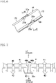
- Each of the first to fourth heater sections A1 to A4 is elongated in the lateral direction of the electric heater 1, as illustrated in FIG. 4 .
- the first heater section A1 is located at the uppermost position
- the fourth heater section A4 is located at the lowermost position.
- the second heater section A2 is located below the first heater section A1.
- the third heater section A3 is located between the second heater section A2 and the fourth heater section A4. Fins 2 are provided at upper and lower surfaces of each of the first to fourth heater sections A1 to A4. That is, the first to fourth heater sections A1 to A4 and the fins 2 are stacked to one another in a vertical direction intersecting with the flow direction of the outside air.
- the fins 2 are corrugated fins made, for example, from a thin plate material made of an aluminum alloy, and serve as a heat transfer member for transferring heat of the first to fourth heater sections A1 to A4 to the outside air. Corrugations of the fins 2 are arranged next to one another in the lateral direction of the electric heater 1. Each of the fins 2 extends, in the housing 3, from the left end to the right end of the housing 3. The outside air flows through the fins 2. Electric power may be controlled to be supplied independently to the first to fourth heater sections A1 to A4, or may be supplied to all of the first to fourth heater sections A1 to A4.
- the first heater section A1 includes a plurality of PTC elements 10, 10, ... , an upper electrode plate (i.e., a first conductive member) 12, a lower electrode plate (i.e., a second conductive member) 13, and a holder 14.
- Each of the PTC elements 10 is a heater element which generates heat by being supplied with electric power, and has a plate-like shape elongated in the lateral direction of the electric heater 1.
- four PTC elements 10 are arranged apart from one another in the lateral direction, but the number and arrangement of the PTC elements 10 are merely examples.
- the upper and lower electrode plates 12 and 13 are formed from a conductive metal plate member, and are electrically connected to the PTC elements 10 when brought into contact with the PTC elements 10.
- the upper electrode plate 12 extends in the lateral direction.
- a through hole 12a which passes through the upper electrode plate 12 in a vertical direction (i.e., in a thickness direction of the upper electrode plate 12) is formed at a right end portion of the upper electrode plate 12.
- a left end portion of the upper electrode plate 12 is bent upward and then bent toward the left to form a connecting portion 12b.
- the connecting portion 12b is connectable with a harness (not shown) to which electric power of a battery loaded on a vehicle is supplied.
- the lower electrode plate 13 also extends in the lateral direction.
- a through hole 13a which passes through the lower electrode plate 13 in the vertical direction (i.e., in the thickness direction of the lower electrode plate 13) is formed at a right end portion of the lower electrode plate 13.
- a left end portion of the lower electrode plate 13 is a connecting portion 13b extending toward the left.
- the connecting portion 13b of the lower electrode plate 13 and the connecting portion 12b of the upper electrode plate 12 are apart from each other in the vertical direction.
- the connecting portion 13b of the lower electrode plate 13 is also connectable with the harness (not shown).
- the PTC elements 10, 10, ... are disposed between the upper and lower electrode plates 12 and 13. That is, the upper and lower electrode plates 12 and 13 are disposed so as to sandwich, and touch, the PTC elements 10, 10, ... , from both sides in a stacking direction of the first to fourth heater sections A1 to A4 and the fins 2 to supply electric power to the PTC elements 10, 10, ... , from outside.
- the holder 14 is made of a heat resistant, electrically insulating resin material, and is intended to hold and combine the PTC elements 10, 10, ... , and the upper and lower electrode plates 12 and 13. As illustrated in FIG. 5 , the holder 14 has a frame-like shape that surrounds the peripheries of the PTC elements 10, 10, ... , and the upper and lower electrode plates 12 and 13.
- the holder 14 includes: a downstream wall 20 extending along downstream edges of the upper and lower electrode plates 12 and 13 in the flow direction of the outside air; an upstream wall 21 extending along upstream edges of the upper and lower electrode plates 12 and 13 in the flow direction of the outside air; a left wall 22 extending to connect left ends of the downstream wall 20 and the upstream wall 21; and a right wall 23 extending to connect right ends of the downstream wall 20 and the upstream wall 21.
- An upper portion of the left wall 22 protrudes upward beyond upper portions of the downstream wall 20 and the upstream wall 21.
- the connecting portion 12b of the upper electrode plate 12 is fitted to this upper portion of the left wall 22 from above.
- the connecting portion 13b of the lower electrode plate 13 is fitted to a lower portion of the left wall 22 from below.
- the downstream wall 20 and the upstream wall 21 have shortest vertical dimensions, when the vertical dimensions are compared among the downstream wall 20, upstream wall 21, left wall 22, and right wall 23. As illustrated in FIG. 3 and 10 , the vertical dimensions of the downstream wall 20 and the upstream wall 21 are determined to be longer than the total vertical dimensions of the PTC element 10, the upper electrode plate 12, and the lower electrode plate 13.
- the downstream wall 20 is provided with four flat portions 20a, 20a, ... , spaced apart from each other in the lateral direction.
- Each of the flat portions 20a is vertically flat.
- each of the flat portions 20a of the downstream wall 20 has, on its inner surface (i.e., the inner surface of the holder 14), a downstream upper engagement portion (i.e., a first engagement portion) 20b, a downstream lower engagement portion (i.e., a second engagement portion) 20c, and a downstream projection 20d.
- the downstream upper engagement portion 20b engages with the upper electrode plate 12 from a side opposite to the PTC element 10 with respect to the upper electrode plate 12 (i.e., from above).
- the downstream lower engagement portion 20c engages with the lower electrode plate 13 from a side opposite to the PTC element 10 with respect to the lower electrode plate 13 (i.e., from below).
- the downstream projection 20d projects toward the inside of the holder 14 from a position between the downstream upper engagement portion 20b and the downstream lower engagement portion 20c.
- the downstream upper engagement portion 20b and the downstream lower engagement portion 20c are each configured as a protrusion which projects toward the inside of the holder 14.
- the downstream upper engagement portion 20b is located at a position closer to the right end of the flat portion 20a, whereas the downstream lower engagement portion 20c is located at a position closer to the left end of the flat portion 20a. That is, the downstream upper engagement portion 20b and the downstream lower engagement portion 20c are arranged so as not to overlap with each other, when the holder 14 is viewed in the stacking direction along which the first to fourth heater sections A1 to A4 and the fins 2 are stacked to one another. Thus, the downstream upper engagement portion 20b and the downstream lower engagement portion 20c do not serve as undercuts in forming the holder 14. This configuration does not require a sliding mold to avoid the undercuts, which may reduce the costs for the mold.
- the vertical distance between the downstream upper engagement portion 20b and the downstream lower engagement portion 20c is determined to be longer than the total vertical dimensions of the PTC element 10, the upper electrode plate 12, and the lower electrode plate 13. Further, the dimension of the downstream projection 20d in the stacking direction (i.e., the vertical direction) is determined to be shorter than the dimension of the PTC element 10 in the stacking direction.
- the upstream wall 21 is also provided with four flat portions 21a, 21a, ... , spaced apart from each other in the lateral direction.
- Each of the flat portions 21a is arranged at a position opposed to a corresponding one of the flat portions 20a of the downstream wall 20, and is vertically flat.
- each of the flat portions 21a of the upstream wall 21 has, on its inner surface (i.e., the inner surface of the holder 14), an upstream upper engagement portion (i.e., a first engagement portion) 21b, an upstream lower engagement portion (i.e., a second engagement portion) 21c, and an upstream projection 21d.
- the upstream upper engagement portion 21b engages with the upper electrode plate 12 from a side opposite to the PTC element 10 with respect to the upper electrode plate 12 (i.e., from above).
- the upstream lower engagement portion 21c engages with the lower electrode plate 13 from a side opposite to the PTC element 10 with respect to the lower electrode plate 13 (i.e., from below).
- the upstream projection 21d projects toward the inside of the holder 14 from a position between the upstream upper engagement portion 21b and the upstream lower engagement portion 21c.
- the upstream upper engagement portion 21b and the upstream lower engagement portion 21c are each comprised of a protrusion which projects toward the inside of the holder 14.
- the upstream upper engagement portion 21b is located at a position closer to the left end of the flat portion 21a, whereas the upstream lower engagement portion 21c is located at a position closer to the right end of the flat portion 21a. That is, the upstream upper engagement portion 21b and the upstream lower engagement portion 21c are arranged so as not to overlap with each other, when the holder 14 is viewed in the stacking direction along which the first to fourth heater sections A1 to A4 and the fins 2 are stacked to one another. Thus, the upstream upper engagement portion 21b and the upstream lower engagement portion 21c do not serve as undercuts in forming the holder 14. This may reduce the costs for the mold.
- the vertical distance between the upstream upper engagement portion 21b and the upstream lower engagement portion 21c is determined to be longer than the total vertical dimensions of the PTC element 10, the upper electrode plate 12, and the lower electrode plate 13. Further, the dimension of the upstream projection 21d in the stacking direction (i.e., the vertical direction) is determined to be shorter than the dimension of the PTC element 10 in the stacking direction.
- the distance between the downstream upper engagement portion 20b and the downstream lower engagement portion 20c, and the distance between the upstream upper engagement portion 21b and the upstream lower engagement portion 21c, to be the distances described above allows the upper and lower electrode plates 12 and 13, as well as the PTC elements 10, to be moved in the vertical direction in the holder 14. That is, the upper electrode plate 12 is movable in the vertical direction between the downstream upper engagement portion 20b and the downstream lower engagement portion 20c, and between the upstream upper engagement portion 21b and the upstream lower engagement portion 21c. This configuration allows for displacement of the upper electrode plate 12 in a direction closer to and away from the lower electrode plate 13.
- the lower electrode plate 13 is movable in the vertical direction between the downstream upper engagement portion 20b and the downstream lower engagement portion 20c, and between the upstream upper engagement portion 21b and the upstream lower engagement portion 21c. This configuration allows for displacement of the lower electrode plate 13 in the direction closer to and away from the upper electrode plate 12.
- the housing 3 is a combination of an upstream housing member 30 and a downstream housing member 31 divided along the flow direction of the outside air.
- the upstream and downstream housing members 30 and 31 are made of a heat resistant, electrically insulating resin material.
- the upstream housing member 30 is provided with an upstream opening 30a through which the outside air flows.
- the downstream housing member 31 is provided with a downstream opening 31a through which the outside air flows.
- the upstream opening 30a and the downstream opening 31a have approximately the same size and shape.
- the downstream opening 31a of the downstream housing member 31 is intended for inserting the spring member 4 in the housing 3 from outside.
- the reinforcing member 31c has an upper end portion continuous with a lower surface of an upper wall portion of the downstream housing member 31.
- the reinforcing member 31c has a lower end portion continuous with an upper surface of a lower wall portion of the downstream housing member 31.
- the upper end portions or the lower end portions of the reinforcing members 31c arranged next to each other are connected together.
- the upstream housing member 30 is also provided with reinforcing members 30c similar to those of the downstream housing member 31.
- This configuration prevents the first to fourth heater sections A1 to A4 from being strongly pressed against the reinforcing members 30c and 31c, and if a compression force is applied to the first to fourth heater sections A1 to A4 by the spring member 4 in the housing 3, allows the first to fourth heater sections A1 to A4 to be moved in the vertical direction by the compression force.
- the spring member 4 is assembled inside the housing 3, and applies a compression force to the first to fourth heater sections A1 to A4 and the fins 2 in the stacking direction of the heater sections A1 to A4 and the fins 2.
- the spring member 4 is formed, for example, from an elastic metal plate member, and extends from a left end portion to a right end portion of the housing 3.
- the spring member 4 includes a plate portion 40, a plurality of upstream biasing portions 41, and a plurality of downstream biasing portions 42.
- the plate portion 40 extends in the lateral direction.
- Each of the upstream biasing portions 41 is bent upward from an upstream edge of the plate portion 40 in the flow direction of the outside air, and then leans toward the downstream side.
- Each of the downstream biasing portions 42 is bent upward from a downstream edge of the plate portion 40 in the flow direction of the outside air, and then leans toward the upstream side.
- the upstream biasing portions 41 are arranged apart from each other in the lateral direction.
- the downstream biasing portions 42 are arranged similarly to the upstream biasing portions 41.
- the plate portion 40 of the spring member 4 has a lower surface which touches a top surface of the uppermost fin 2.
- Upper ends of the upstream biasing portion 41 and downstream biasing portion 42 touch an inside surface of the upper wall of the housing 3.
- a compression force is applied to the first to fourth heater sections A1 to A4 and the fins 2 in the stacking direction mainly due to elastic deformation of the upstream biasing portion 41 and the downstream biasing portion 42 in a gap between the uppermost fin 2 and the inside surface of the upper wall of the housing 3.
- the plate portion 40 of the spring member 4 has a notch 40a between adjacent upstream biasing portions 41, 41 and adjacent downstream biasing portions 42, 42.
- the reinforcing member 31c of the downstream housing member 31 is fitted to the notch 40a.
- the notch 40a is elongated from the upstream edge to the downstream edge of the plate portion 40, that is, elongated in the direction along which the spring member 4 is inserted in the downstream opening 31a.
- the notch 40a is open at the upstream edge of the plate portion 40. Both lateral edges of the notch 40a on the upstream side are configured as tilt edges 40b for guiding the reinforcing member 31c into the notch 40a.
- the plate portion 40 of the spring member 4 is provided with a contact member 43 which comes into contact with the reinforcing member 31c of the downstream housing member 31 from outside the housing 3.
- the contact member 43 is like a plate which extends upward from near the downstream end of the notch 40a in the flow direction of the outside air.
- the reinforcing member 31c is in contact with an upstream side surface of the contact member 43 in the flow direction of the outside air.
- the left and right caps 5 and 6 are made of a heat resistant, electrically insulating resin material. As illustrated in FIG. 1 , the left cap 5 covers the connecting portions 12b and 13b of the first to fourth heater sections A1 to A4, as well as the left ends of the upstream housing member 30 and the downstream housing member 31. The right cap 6 covers the right ends of the upstream housing member 30 and the downstream housing member 31. The left and right caps 5 and 6 are attached to the stated positions after combining the upstream and downstream housing members 30 and 31.
- the first to fourth heater sections A1 to A4 and the fins 2 are stacked to one another, and mounted on the upstream housing member 30 or the downstream housing member 31.
- the downstream and upstream upper engagement portions 20b and 21b of the holder 14 of the first heater section A1 engage with the upper electrode plate 12 from above
- the downstream and upstream lower engagement portions 20c and 21c engage with the lower electrode plate 13 from below.
- the upper and lower electrode plates 12 and 13 will not come off the holder 14, and be kept in an integrally combined state with the PTC elements 10.
- This configuration facilitates the assembly of the first to fourth heater sections A1 to A4 and the fins 2 to the housing 3. Note that the spring member 4 is not yet assembled at this moment.
- the upstream housing member 30 and the downstream housing member 31 are combined to each other.
- the upstream housing member 30 and the downstream housing member 31 are integrally combined by inserting and fitting the fitting protrusion 31b into the fitting recess 30b.
- the absence of the spring member 4 in combining the upstream housing member 30 and the downstream housing member 31 facilitates the assembly because the reaction force of the spring member 4 is not applied to the upstream and downstream housing members 30 and 31.
- the spring member 4 is inserted into the housing 3 through the downstream opening 31a of the housing 3.
- the reaction force of the spring member 4 is applied when the spring member 40 is inserted in the housing 3.
- only the spring member 4 needs to be pressed during the insertion, which facilitates the assembly.
- the compression force of the spring member 4 is applied to the first to fourth heater sections A1 to A4, as well.
- the upper electrode plate 12 held by the holder 14 is displaceable in the direction closer to and away from the lower electrode plate 13.
- the degree to which an amount of heat generated by the PTC elements 10 declines may be reduced.
- the above configuration allows the spring member 4 to be inserted in, and assembled to, the housing 3, with the downstream reinforcing member 31c fitted to the notch 40a of the spring member 4, which facilitates the assembly.
- the lower electrode plate 13 may be insert-molded in the holder 14 as a variation of the embodiment, as illustrated in FIG. 11 .
- the lower electrode plate 13 is not displaceable with respect to the holder 14, whereas the upper electrode plate 12 is allowed to displace in the direction closer to and away from the lower electrode plate 13.
- an electric heater according to the present invention may be used, for example, as an air heater for a vehicle air conditioner.
Landscapes
- Engineering & Computer Science (AREA)
- Physics & Mathematics (AREA)
- Thermal Sciences (AREA)
- Chemical & Material Sciences (AREA)
- Combustion & Propulsion (AREA)
- Mechanical Engineering (AREA)
- General Engineering & Computer Science (AREA)
- Resistance Heating (AREA)
- Air-Conditioning For Vehicles (AREA)
Claims (6)
- Dispositif de chauffage électrique comprenant :une section de chauffage (Al-A4) ayant un élément de chauffage (10) qui génère de la chaleur en étant alimenté en énergie électrique ;une ailette (2) qui transfère de la chaleur de la section de chauffage à l'air extérieur ;un boîtier (3) qui maintient la section de chauffage et l'ailette empilées l'une sur l'autre dans une direction verticale coupant une direction d'écoulement de l'air extérieur ; etun membre ressort (4) assemblé au boîtier (3) pour appliquer une force de compression à la section de chauffage (Al-A4) et à l'ailette (2) dans une direction d'empilement de celles-ci, dans lequella section de chauffage (Al-A4) inclut : un membre conducteur supérieur (12) et un membre conducteur inférieur (13) qui sont agencés pour prendre en sandwich l'élément de chauffage (10) des deux côtés dans la direction d'empilement et toucher l'élément de chauffage (10) pour fournir de l'énergie électrique à l'élément de chauffage depuis l'extérieur; et un support (14) qui maintient l'élément de chauffage (10), le membre conducteur supérieur (12) et le membre conducteur inférieur (13),dans lequelle support (14) est muni de parties d'engagement supérieures amont et aval (21b, 20b) qui s'engagent avec le membre conducteur supérieur (12) depuis un côté opposé à l'élément de chauffage (10) par rapport au membre conducteur supérieur (12), et de parties d'engagement inférieures amont et aval (21c, 20c) qui s'engagent avec le membre conducteur inférieur (13) depuis un côté opposé à l'élément de chauffage (10) par rapport au membre conducteur inférieur (13),une distance verticale entre la partie d'engagement supérieure amont (21b) et la partie d'engagement inférieure amont (21c) et une distance verticale entre la partie d'engagement supérieure aval (20b) et la partie d'engagement inférieure aval (20c) sont réglées pour être plus longues qu'une dimension verticale totale d'une épaisseur du membre conducteur supérieur (12), d'une épaisseur du membre conducteur inférieur (13) et d'une épaisseur de l'élément de chauffage (10), dans lequelle support (14) est configuré pour permettre au membre conducteur supérieur (12) d'être déplacé dans la direction verticale pour se rapprocher et s'éloigner du membre conducteur inférieur (13) dans un espace entre la partie d'engagement supérieure amont (21b) et la partie d'engagement inférieure amont (21c) et dans un espace entre la partie d'engagement supérieure aval (20b) et la partie d'engagement inférieure aval (20c).
- Dispositif de chauffage électrique selon la revendication 1, dans lequelle support (14) a une forme de type cadre qui entoure des périphéries du membre conducteur supérieur (12) et du membre conducteur inférieur (13), etchacune des parties d'engagement supérieures aval et amont (20b, 21b) et des parties d'engagement inférieures aval et amont (20c, 21c) est configurée comme une protubérance qui fait saillie vers l'intérieur du support (14) depuis une surface intérieure du support (14).
- Dispositif de chauffage électrique selon la revendication 2, dans lequelle support (14) est fait d'un matériau en résine, etla partie d'engagement supérieure amont (21b) et la partie d'engagement inférieure amont (21c) sont agencées de manière à ne pas se chevaucher l'une l'autre lorsque le support (14) est vu dans la direction d'empilement et la partie d'engagement supérieure aval (20b) et la partie d'engagement inférieure aval (20c) sont agencées de manière à ne pas se chevaucher l'une l'autre lorsque le support (14) est vu dans la direction d'empilement.
- Dispositif de chauffage électrique selon la revendication 1, dans lequel
le membre conducteur inférieur (13) est moulé par insertion dans le support (14). - Dispositif de chauffage électrique selon la revendication 1, dans lequel
le support (14) est configuré pour permettre à l'élément conducteur inférieur (13) d'être déplacé dans une direction verticale pour se rapprocher et s'éloigner du membre conducteur supérieur (12) dans un espace entre la partie d'engagement supérieure amont (21b) et la partie d'engagement inférieure amont (21c) et dans un espace entre la partie d'engagement supérieure aval (20b) et la partie d'engagement inférieure aval (20c). - Dispositif de chauffage électrique selon la revendication 2, dans lequella surface intérieure du support (14) est munie de projections (20d, 21d) qui font saillie vers l'intérieur du support (14) depuis une position entre la surface, de la partie d'engagement supérieure amont (21b), faisant face au membre conducteur supérieur (12) et la surface, de la partie d'engagement inférieure amont (21c), faisant face au membre conducteur inférieur (13), et depuis une position entre la surface, de la partie d'engagement supérieure aval (21b), faisant face au membre conducteur supérieur (12) et la surface, de la partie d'engagement inférieure aval (21c), faisant face au membre conducteur inférieur (13), etune dimension des projections (20d, 21d) dans la direction d'empilement est réglée pour être plus courte qu'une dimension de l'élément de chauffage dans la direction d'empilement.
Applications Claiming Priority (2)
| Application Number | Priority Date | Filing Date | Title |
|---|---|---|---|
| JP2015145013A JP6568738B2 (ja) | 2015-07-22 | 2015-07-22 | 電気式ヒータ |
| PCT/JP2016/003209 WO2017013846A1 (fr) | 2015-07-22 | 2016-07-05 | Dispositif de chauffage électrique |
Publications (3)
| Publication Number | Publication Date |
|---|---|
| EP3328157A1 EP3328157A1 (fr) | 2018-05-30 |
| EP3328157A4 EP3328157A4 (fr) | 2018-08-01 |
| EP3328157B1 true EP3328157B1 (fr) | 2022-09-28 |
Family
ID=57834265
Family Applications (1)
| Application Number | Title | Priority Date | Filing Date |
|---|---|---|---|
| EP16827414.0A Active EP3328157B1 (fr) | 2015-07-22 | 2016-07-05 | Dispositif de chauffage électrique |
Country Status (4)
| Country | Link |
|---|---|
| EP (1) | EP3328157B1 (fr) |
| JP (1) | JP6568738B2 (fr) |
| CN (1) | CN107615878B (fr) |
| WO (1) | WO2017013846A1 (fr) |
Families Citing this family (2)
| Publication number | Priority date | Publication date | Assignee | Title |
|---|---|---|---|---|
| FR3083744A1 (fr) * | 2018-07-13 | 2020-01-17 | Valeo Systemes Thermiques | Cadre de dispositif de chauffage electrique de vehicule |
| FR3126837B1 (fr) * | 2021-09-03 | 2023-09-08 | Valeo Systemes Thermiques | Radiateur électrique d’une installation de ventilation, de chauffage et/ou d’air climatisé. |
Family Cites Families (13)
| Publication number | Priority date | Publication date | Assignee | Title |
|---|---|---|---|---|
| DE2845965C2 (de) * | 1978-10-21 | 1983-01-20 | Fritz Eichenauer GmbH & Co KG, 6744 Kandel | Elektrisches Widerstandsheizelement |
| JPH07153555A (ja) * | 1993-11-30 | 1995-06-16 | Murata Mfg Co Ltd | 正特性サーミスタヒータ及びそれを用いた正特性サーミスタヒータ装置 |
| DE10118600C2 (de) * | 2001-04-12 | 2003-05-28 | Webasto Thermosysteme Gmbh | Elektrische Heizeinrichtung |
| DE10143852B4 (de) * | 2001-09-06 | 2008-04-17 | Webasto Ag | Heizkörper |
| ITMI20021226A1 (it) * | 2002-06-05 | 2003-12-05 | Cebi Spa | Riscaldatore elettrico ad elementi ptc particolarmente per impianti di aereazione dell'abitacolo di autoveicoli |
| ES2263730T3 (es) * | 2002-12-19 | 2006-12-16 | CATEM GMBH & CO.KG | Dispositivo calefactor electrico con cuerpo envolvente. |
| PT1580495E (pt) * | 2004-03-22 | 2011-12-15 | Halla Climate Control Corp | Aquecedor eléctrico |
| EP1768457B1 (fr) * | 2005-09-23 | 2008-05-14 | Catem GmbH & Co.KG | Element chauffant d'un dispositif de chauffage |
| JP2008071553A (ja) * | 2006-09-13 | 2008-03-27 | Calsonic Kansei Corp | 電気ヒータ装置およびその製造方法 |
| EP2017546B1 (fr) * | 2007-07-18 | 2016-04-13 | Eberspächer catem GmbH & Co. KG | Procédé de fabrication d'un dispositif de chauffage électrique tout comme dispositif de chauffage électrique |
| EP2395295B1 (fr) * | 2010-06-11 | 2013-03-06 | Behr GmbH & Co. KG | Echangeur de chaleur |
| EP2608633B1 (fr) * | 2011-12-22 | 2020-08-26 | Eberspächer catem GmbH & Co. KG | Elément générateur de chaleur |
| ITRM20120056A1 (it) * | 2012-02-20 | 2013-08-21 | Bitron Spa | DISPOSITIVO DI RISCALDAMENTO, IN PARTICOLARE PER IL RISCALDAMENTO DELLÂeuro¿ABITACOLO DI UNÂeuro¿AUTOMOBILE, ELEMENTO RADIANTE E RELATIVO METODO DI MONTAGGIO DI DETTO DISPOSITIVO. |
-
2015
- 2015-07-22 JP JP2015145013A patent/JP6568738B2/ja active Active
-
2016
- 2016-07-05 CN CN201680029097.6A patent/CN107615878B/zh active Active
- 2016-07-05 WO PCT/JP2016/003209 patent/WO2017013846A1/fr unknown
- 2016-07-05 EP EP16827414.0A patent/EP3328157B1/fr active Active
Also Published As
| Publication number | Publication date |
|---|---|
| EP3328157A1 (fr) | 2018-05-30 |
| WO2017013846A1 (fr) | 2017-01-26 |
| JP2017027776A (ja) | 2017-02-02 |
| CN107615878B (zh) | 2020-09-22 |
| JP6568738B2 (ja) | 2019-08-28 |
| CN107615878A (zh) | 2018-01-19 |
| EP3328157A4 (fr) | 2018-08-01 |
Similar Documents
| Publication | Publication Date | Title |
|---|---|---|
| CN105814749B (zh) | 用于插接式连接器的保持框架 | |
| JP4059840B2 (ja) | ハウジングを備えた電気ヒータ | |
| CN105814748B (zh) | 插接式连接器的保持框架 | |
| TWI403032B (zh) | 彈簧外露型母端子 | |
| JP3929988B2 (ja) | ハウジングを備えた電気加熱装置 | |
| JP6075801B2 (ja) | 加熱素子用の冷却・保持体、ヒータ、および冷却・保持体の製造方法 | |
| US7482557B2 (en) | Lamella type radiator element having foldable projections and a notch | |
| JP5999381B2 (ja) | 駆動装置 | |
| EP3328157B1 (fr) | Dispositif de chauffage électrique | |
| WO2007129608A1 (fr) | Dispositif de chauffage électrique | |
| CN104838569A (zh) | 致动器 | |
| JP6513522B2 (ja) | 電気式ヒータ | |
| EP3530501B1 (fr) | Dispositif chauffant électrique de climatiseur de véhicule | |
| JP2007149504A (ja) | 雌端子及びコネクタ | |
| WO2017119206A1 (fr) | Module de batteries | |
| EP3530502B1 (fr) | Dispositif de chauffage électrique dans climatiseur pour véhicule et son procédé de fabrication | |
| JP3804517B2 (ja) | 車両の暖房用熱交換器 | |
| KR102002378B1 (ko) | Ptc 히터의 ptc 코어 구조 | |
| CN113692072A (zh) | 电加热装置 | |
| JP6472650B2 (ja) | 車両用空調装置の電気式ヒータ | |
| JP7529996B2 (ja) | 電気式ヒータ | |
| JP2007300005A (ja) | 電気ヒータ装置 | |
| EP3530503A1 (fr) | Chauffage électrique | |
| JP2020059382A (ja) | 車両用空調装置の電気式ヒータ | |
| KR20230164805A (ko) | 차량용 히터 조립체 |
Legal Events
| Date | Code | Title | Description |
|---|---|---|---|
| STAA | Information on the status of an ep patent application or granted ep patent |
Free format text: STATUS: THE INTERNATIONAL PUBLICATION HAS BEEN MADE |
|
| PUAI | Public reference made under article 153(3) epc to a published international application that has entered the european phase |
Free format text: ORIGINAL CODE: 0009012 |
|
| STAA | Information on the status of an ep patent application or granted ep patent |
Free format text: STATUS: REQUEST FOR EXAMINATION WAS MADE |
|
| 17P | Request for examination filed |
Effective date: 20171117 |
|
| AK | Designated contracting states |
Kind code of ref document: A1 Designated state(s): AL AT BE BG CH CY CZ DE DK EE ES FI FR GB GR HR HU IE IS IT LI LT LU LV MC MK MT NL NO PL PT RO RS SE SI SK SM TR |
|
| AX | Request for extension of the european patent |
Extension state: BA ME |
|
| A4 | Supplementary search report drawn up and despatched |
Effective date: 20180629 |
|
| RIC1 | Information provided on ipc code assigned before grant |
Ipc: F24H 9/18 20060101ALI20180625BHEP Ipc: B60H 1/03 20060101ALI20180625BHEP Ipc: B60H 1/22 20060101ALI20180625BHEP Ipc: H05B 3/06 20060101AFI20180625BHEP Ipc: F24H 3/04 20060101ALI20180625BHEP |
|
| DAV | Request for validation of the european patent (deleted) | ||
| DAX | Request for extension of the european patent (deleted) | ||
| STAA | Information on the status of an ep patent application or granted ep patent |
Free format text: STATUS: EXAMINATION IS IN PROGRESS |
|
| 17Q | First examination report despatched |
Effective date: 20200121 |
|
| STAA | Information on the status of an ep patent application or granted ep patent |
Free format text: STATUS: EXAMINATION IS IN PROGRESS |
|
| REG | Reference to a national code |
Ref country code: DE Ref legal event code: R079 Ref document number: 602016075319 Country of ref document: DE Free format text: PREVIOUS MAIN CLASS: H05B0003060000 Ipc: F24H0003040000 |
|
| GRAP | Despatch of communication of intention to grant a patent |
Free format text: ORIGINAL CODE: EPIDOSNIGR1 |
|
| STAA | Information on the status of an ep patent application or granted ep patent |
Free format text: STATUS: GRANT OF PATENT IS INTENDED |
|
| RIC1 | Information provided on ipc code assigned before grant |
Ipc: H05B 3/06 20060101ALI20220413BHEP Ipc: F24H 9/1863 20220101ALI20220413BHEP Ipc: F24H 3/04 20060101AFI20220413BHEP |
|
| INTG | Intention to grant announced |
Effective date: 20220518 |
|
| GRAS | Grant fee paid |
Free format text: ORIGINAL CODE: EPIDOSNIGR3 |
|
| GRAA | (expected) grant |
Free format text: ORIGINAL CODE: 0009210 |
|
| STAA | Information on the status of an ep patent application or granted ep patent |
Free format text: STATUS: THE PATENT HAS BEEN GRANTED |
|
| AK | Designated contracting states |
Kind code of ref document: B1 Designated state(s): AL AT BE BG CH CY CZ DE DK EE ES FI FR GB GR HR HU IE IS IT LI LT LU LV MC MK MT NL NO PL PT RO RS SE SI SK SM TR |
|
| REG | Reference to a national code |
Ref country code: GB Ref legal event code: FG4D |
|
| REG | Reference to a national code |
Ref country code: CH Ref legal event code: EP |
|
| REG | Reference to a national code |
Ref country code: DE Ref legal event code: R096 Ref document number: 602016075319 Country of ref document: DE |
|
| REG | Reference to a national code |
Ref country code: AT Ref legal event code: REF Ref document number: 1521476 Country of ref document: AT Kind code of ref document: T Effective date: 20221015 |
|
| REG | Reference to a national code |
Ref country code: IE Ref legal event code: FG4D |
|
| REG | Reference to a national code |
Ref country code: LT Ref legal event code: MG9D |
|
| PG25 | Lapsed in a contracting state [announced via postgrant information from national office to epo] |
Ref country code: SE Free format text: LAPSE BECAUSE OF FAILURE TO SUBMIT A TRANSLATION OF THE DESCRIPTION OR TO PAY THE FEE WITHIN THE PRESCRIBED TIME-LIMIT Effective date: 20220928 Ref country code: RS Free format text: LAPSE BECAUSE OF FAILURE TO SUBMIT A TRANSLATION OF THE DESCRIPTION OR TO PAY THE FEE WITHIN THE PRESCRIBED TIME-LIMIT Effective date: 20220928 Ref country code: NO Free format text: LAPSE BECAUSE OF FAILURE TO SUBMIT A TRANSLATION OF THE DESCRIPTION OR TO PAY THE FEE WITHIN THE PRESCRIBED TIME-LIMIT Effective date: 20221228 Ref country code: LV Free format text: LAPSE BECAUSE OF FAILURE TO SUBMIT A TRANSLATION OF THE DESCRIPTION OR TO PAY THE FEE WITHIN THE PRESCRIBED TIME-LIMIT Effective date: 20220928 Ref country code: LT Free format text: LAPSE BECAUSE OF FAILURE TO SUBMIT A TRANSLATION OF THE DESCRIPTION OR TO PAY THE FEE WITHIN THE PRESCRIBED TIME-LIMIT Effective date: 20220928 Ref country code: FI Free format text: LAPSE BECAUSE OF FAILURE TO SUBMIT A TRANSLATION OF THE DESCRIPTION OR TO PAY THE FEE WITHIN THE PRESCRIBED TIME-LIMIT Effective date: 20220928 |
|
| REG | Reference to a national code |
Ref country code: NL Ref legal event code: MP Effective date: 20220928 |
|
| REG | Reference to a national code |
Ref country code: AT Ref legal event code: MK05 Ref document number: 1521476 Country of ref document: AT Kind code of ref document: T Effective date: 20220928 |
|
| PG25 | Lapsed in a contracting state [announced via postgrant information from national office to epo] |
Ref country code: HR Free format text: LAPSE BECAUSE OF FAILURE TO SUBMIT A TRANSLATION OF THE DESCRIPTION OR TO PAY THE FEE WITHIN THE PRESCRIBED TIME-LIMIT Effective date: 20220928 Ref country code: GR Free format text: LAPSE BECAUSE OF FAILURE TO SUBMIT A TRANSLATION OF THE DESCRIPTION OR TO PAY THE FEE WITHIN THE PRESCRIBED TIME-LIMIT Effective date: 20221229 |
|
| PG25 | Lapsed in a contracting state [announced via postgrant information from national office to epo] |
Ref country code: SM Free format text: LAPSE BECAUSE OF FAILURE TO SUBMIT A TRANSLATION OF THE DESCRIPTION OR TO PAY THE FEE WITHIN THE PRESCRIBED TIME-LIMIT Effective date: 20220928 Ref country code: RO Free format text: LAPSE BECAUSE OF FAILURE TO SUBMIT A TRANSLATION OF THE DESCRIPTION OR TO PAY THE FEE WITHIN THE PRESCRIBED TIME-LIMIT Effective date: 20220928 Ref country code: PT Free format text: LAPSE BECAUSE OF FAILURE TO SUBMIT A TRANSLATION OF THE DESCRIPTION OR TO PAY THE FEE WITHIN THE PRESCRIBED TIME-LIMIT Effective date: 20230130 Ref country code: ES Free format text: LAPSE BECAUSE OF FAILURE TO SUBMIT A TRANSLATION OF THE DESCRIPTION OR TO PAY THE FEE WITHIN THE PRESCRIBED TIME-LIMIT Effective date: 20220928 Ref country code: CZ Free format text: LAPSE BECAUSE OF FAILURE TO SUBMIT A TRANSLATION OF THE DESCRIPTION OR TO PAY THE FEE WITHIN THE PRESCRIBED TIME-LIMIT Effective date: 20220928 Ref country code: AT Free format text: LAPSE BECAUSE OF FAILURE TO SUBMIT A TRANSLATION OF THE DESCRIPTION OR TO PAY THE FEE WITHIN THE PRESCRIBED TIME-LIMIT Effective date: 20220928 |
|
| PG25 | Lapsed in a contracting state [announced via postgrant information from national office to epo] |
Ref country code: SK Free format text: LAPSE BECAUSE OF FAILURE TO SUBMIT A TRANSLATION OF THE DESCRIPTION OR TO PAY THE FEE WITHIN THE PRESCRIBED TIME-LIMIT Effective date: 20220928 Ref country code: PL Free format text: LAPSE BECAUSE OF FAILURE TO SUBMIT A TRANSLATION OF THE DESCRIPTION OR TO PAY THE FEE WITHIN THE PRESCRIBED TIME-LIMIT Effective date: 20220928 Ref country code: IS Free format text: LAPSE BECAUSE OF FAILURE TO SUBMIT A TRANSLATION OF THE DESCRIPTION OR TO PAY THE FEE WITHIN THE PRESCRIBED TIME-LIMIT Effective date: 20230128 Ref country code: EE Free format text: LAPSE BECAUSE OF FAILURE TO SUBMIT A TRANSLATION OF THE DESCRIPTION OR TO PAY THE FEE WITHIN THE PRESCRIBED TIME-LIMIT Effective date: 20220928 |
|
| REG | Reference to a national code |
Ref country code: DE Ref legal event code: R097 Ref document number: 602016075319 Country of ref document: DE |
|
| PG25 | Lapsed in a contracting state [announced via postgrant information from national office to epo] |
Ref country code: NL Free format text: LAPSE BECAUSE OF FAILURE TO SUBMIT A TRANSLATION OF THE DESCRIPTION OR TO PAY THE FEE WITHIN THE PRESCRIBED TIME-LIMIT Effective date: 20220928 Ref country code: AL Free format text: LAPSE BECAUSE OF FAILURE TO SUBMIT A TRANSLATION OF THE DESCRIPTION OR TO PAY THE FEE WITHIN THE PRESCRIBED TIME-LIMIT Effective date: 20220928 |
|
| PG25 | Lapsed in a contracting state [announced via postgrant information from national office to epo] |
Ref country code: DK Free format text: LAPSE BECAUSE OF FAILURE TO SUBMIT A TRANSLATION OF THE DESCRIPTION OR TO PAY THE FEE WITHIN THE PRESCRIBED TIME-LIMIT Effective date: 20220928 |
|
| PLBE | No opposition filed within time limit |
Free format text: ORIGINAL CODE: 0009261 |
|
| STAA | Information on the status of an ep patent application or granted ep patent |
Free format text: STATUS: NO OPPOSITION FILED WITHIN TIME LIMIT |
|
| 26N | No opposition filed |
Effective date: 20230629 |
|
| PG25 | Lapsed in a contracting state [announced via postgrant information from national office to epo] |
Ref country code: SI Free format text: LAPSE BECAUSE OF FAILURE TO SUBMIT A TRANSLATION OF THE DESCRIPTION OR TO PAY THE FEE WITHIN THE PRESCRIBED TIME-LIMIT Effective date: 20220928 |
|
| PGFP | Annual fee paid to national office [announced via postgrant information from national office to epo] |
Ref country code: FR Payment date: 20230726 Year of fee payment: 8 Ref country code: DE Payment date: 20230719 Year of fee payment: 8 |
|
| PG25 | Lapsed in a contracting state [announced via postgrant information from national office to epo] |
Ref country code: MC Free format text: LAPSE BECAUSE OF FAILURE TO SUBMIT A TRANSLATION OF THE DESCRIPTION OR TO PAY THE FEE WITHIN THE PRESCRIBED TIME-LIMIT Effective date: 20220928 |
|
| PG25 | Lapsed in a contracting state [announced via postgrant information from national office to epo] |
Ref country code: MC Free format text: LAPSE BECAUSE OF FAILURE TO SUBMIT A TRANSLATION OF THE DESCRIPTION OR TO PAY THE FEE WITHIN THE PRESCRIBED TIME-LIMIT Effective date: 20220928 |
|
| REG | Reference to a national code |
Ref country code: CH Ref legal event code: PL |
|
| REG | Reference to a national code |
Ref country code: BE Ref legal event code: MM Effective date: 20230731 |
|
| PG25 | Lapsed in a contracting state [announced via postgrant information from national office to epo] |
Ref country code: LU Free format text: LAPSE BECAUSE OF NON-PAYMENT OF DUE FEES Effective date: 20230705 |
|
| GBPC | Gb: european patent ceased through non-payment of renewal fee |
Effective date: 20230705 |
|
| PG25 | Lapsed in a contracting state [announced via postgrant information from national office to epo] |
Ref country code: LU Free format text: LAPSE BECAUSE OF NON-PAYMENT OF DUE FEES Effective date: 20230705 |
|
| REG | Reference to a national code |
Ref country code: IE Ref legal event code: MM4A |
|
| PG25 | Lapsed in a contracting state [announced via postgrant information from national office to epo] |
Ref country code: CH Free format text: LAPSE BECAUSE OF NON-PAYMENT OF DUE FEES Effective date: 20230731 Ref country code: GB Free format text: LAPSE BECAUSE OF NON-PAYMENT OF DUE FEES Effective date: 20230705 |
|
| PG25 | Lapsed in a contracting state [announced via postgrant information from national office to epo] |
Ref country code: IT Free format text: LAPSE BECAUSE OF FAILURE TO SUBMIT A TRANSLATION OF THE DESCRIPTION OR TO PAY THE FEE WITHIN THE PRESCRIBED TIME-LIMIT Effective date: 20220928 Ref country code: BE Free format text: LAPSE BECAUSE OF NON-PAYMENT OF DUE FEES Effective date: 20230731 |
|
| PG25 | Lapsed in a contracting state [announced via postgrant information from national office to epo] |
Ref country code: IE Free format text: LAPSE BECAUSE OF NON-PAYMENT OF DUE FEES Effective date: 20230705 |
|
| PG25 | Lapsed in a contracting state [announced via postgrant information from national office to epo] |
Ref country code: IE Free format text: LAPSE BECAUSE OF NON-PAYMENT OF DUE FEES Effective date: 20230705 |
|
| PG25 | Lapsed in a contracting state [announced via postgrant information from national office to epo] |
Ref country code: BG Free format text: LAPSE BECAUSE OF FAILURE TO SUBMIT A TRANSLATION OF THE DESCRIPTION OR TO PAY THE FEE WITHIN THE PRESCRIBED TIME-LIMIT Effective date: 20220928 |
|
| PG25 | Lapsed in a contracting state [announced via postgrant information from national office to epo] |
Ref country code: BG Free format text: LAPSE BECAUSE OF FAILURE TO SUBMIT A TRANSLATION OF THE DESCRIPTION OR TO PAY THE FEE WITHIN THE PRESCRIBED TIME-LIMIT Effective date: 20220928 |