EP1875081B1 - Pump - Google Patents
Pump Download PDFInfo
- Publication number
- EP1875081B1 EP1875081B1 EP06726876.3A EP06726876A EP1875081B1 EP 1875081 B1 EP1875081 B1 EP 1875081B1 EP 06726876 A EP06726876 A EP 06726876A EP 1875081 B1 EP1875081 B1 EP 1875081B1
- Authority
- EP
- European Patent Office
- Prior art keywords
- cavity
- pump
- end walls
- walls
- actuator
- Prior art date
- Legal status (The legal status is an assumption and is not a legal conclusion. Google has not performed a legal analysis and makes no representation as to the accuracy of the status listed.)
- Active
Links
Images


Classifications
-
- F—MECHANICAL ENGINEERING; LIGHTING; HEATING; WEAPONS; BLASTING
- F04—POSITIVE - DISPLACEMENT MACHINES FOR LIQUIDS; PUMPS FOR LIQUIDS OR ELASTIC FLUIDS
- F04B—POSITIVE-DISPLACEMENT MACHINES FOR LIQUIDS; PUMPS
- F04B43/00—Machines, pumps, or pumping installations having flexible working members
- F04B43/02—Machines, pumps, or pumping installations having flexible working members having plate-like flexible members, e.g. diaphragms
- F04B43/04—Pumps having electric drive
- F04B43/043—Micropumps
- F04B43/046—Micropumps with piezoelectric drive
-
- F—MECHANICAL ENGINEERING; LIGHTING; HEATING; WEAPONS; BLASTING
- F04—POSITIVE - DISPLACEMENT MACHINES FOR LIQUIDS; PUMPS FOR LIQUIDS OR ELASTIC FLUIDS
- F04B—POSITIVE-DISPLACEMENT MACHINES FOR LIQUIDS; PUMPS
- F04B45/00—Pumps or pumping installations having flexible working members and specially adapted for elastic fluids
- F04B45/04—Pumps or pumping installations having flexible working members and specially adapted for elastic fluids having plate-like flexible members, e.g. diaphragms
- F04B45/047—Pumps having electric drive
-
- F—MECHANICAL ENGINEERING; LIGHTING; HEATING; WEAPONS; BLASTING
- F04—POSITIVE - DISPLACEMENT MACHINES FOR LIQUIDS; PUMPS FOR LIQUIDS OR ELASTIC FLUIDS
- F04F—PUMPING OF FLUID BY DIRECT CONTACT OF ANOTHER FLUID OR BY USING INERTIA OF FLUID TO BE PUMPED; SIPHONS
- F04F7/00—Pumps displacing fluids by using inertia thereof, e.g. by generating vibrations therein
Definitions
- This invention relates to a pump for a fluid and, in particular, to a pump in which the pumping cavity is substantially cylindrical in shape, but is sized such that the aspect ratio is large, i.e. the cavity is disk-shaped.
- thermoacoustics The generation of high amplitude pressure oscillations in closed cavities has received significant attention in the fields of thermoacoustics and pump/compressors. Recent developments in non-linear acoustics have allowed the generation of pressure waves with higher amplitudes than previously thought possible.
- acoustic resonance it is known to use acoustic resonance to achieve fluid pumping from defined inlets and outlets. This can be achieved using a cylindrical cavity with an acoustic driver at one end, which drives an acoustic standing wave. In such a cylindrical cavity, the acoustic pressure wave has limited amplitude. Varying cross-section cavities, such as cone, horn-cone, bulb have been used to achieve high amplitude pressure oscillations thereby significantly increasing the pumping effect. In such high amplitude waves the non-linear mechanisms with energy dissipation have been suppressed. However, high amplitude acoustic resonance has not been employed within disk-shaped cavities in which radial pressure oscillations are excited.
- a linear resonance compressor is also known in which the mass of the drive armature and spring force of a steel diaphragm combine to provide a mechanically resonant drive to the air cavity.
- This drive is coupled to a cylindrical cavity of diameter between 4 and 15cm (depending on the design of the compressor) through a steel diaphragm, which is capable of up to 1.5mm displacement in use.
- the drive frequency is set to between 150 and 300Hz by the mechanical resonance. At this frequency, the radial acoustic wavelength is much longer than the cavity radius. Therefore it can be deduced that radial pressure oscillations are not employed in this cavity pump.
- the low frequency drive mechanism used in this linear resonance compressor incorporates an electromechanical armature, leaf spring suspension, noise enclosure, and vibration mount suspension. This leads to a large overall size of the compressor.
- the present invention aims to overcome one or more of the above identified problems.
- WO 2004/090335 discloses a gas flow generator having an ultrasonic driver, and first and second membranes mounted parallel to each other, wherein operation of the driver causes a gas flow through perforations in one of the membranes.
- a fluid pump comprising:
- h 2 a should be greater than 4 ⁇ 10 -10 m when pumping a liquid, but in the case of pumping a gas, it is preferable that the ratio is greater than 1 ⁇ 10 -7 m.
- the present invention provides a substantially disk-shaped cavity having a high aspect ratio.
- the invention can be thought of as an acoustic pump, in that an acoustic resonance is set up within the cavity.
- the driver velocity typically of the order of 1m s-1
- the geometry of the cavity to give an effective drive velocity far exceeding this value, producing a very high acoustic pressure.
- the high pressure may be seen as arising from the inertial reaction of the air (the air's resistance to motion) to the high acceleration imposed upon it by the combination of the actuator movement and the cavity geometry.
- the present invention overcomes the large size of known linear resonance compressors by replacing the low frequency drive mechanism with a disk actuator, preferably piezoelectric.
- This disk is typically less than 1 mm thick and is tuned to operate at more than 500Hz, preferably 10kHz, more preferably 20kHz or higher.
- a frequency of approximately 20kHz or above provides operation above the threshold of normal human hearing, thereby removing the need for a noise enclosure.
- the frequency of the oscillatory motion is within 20% of the lowest resonant frequency of radial pressure oscillations in the cavity. More preferably, the frequency of the oscillatory motion is, in use, equal to the lowest resonant frequency of radial pressure oscillations in the cavity.
- the high frequency of the present invention significantly reduces the size of the cavity and the overall device. Accordingly, the present invention can be constructed with a cavity volume of less than 10ml, making it ideally suited to micro-device applications.
- a disk provides a low cavity volume and a geometric form able to sustain high amplitude pressure oscillations.
- the end walls defining the cavity are substantially planar and substantially parallel.
- the terms “substantially planar” and “substantially parallel” are intended to include frusto-conical surfaces such as those shown in Figs. 5A and 5B as the change in separation of the two end walls over a typical diameter of 20mm is typically no more than 0.25mm. As such, the end walls are substantially planar and substantially parallel.
- the ratio of the cavity radius to its height is greater than 20, such that the cavity formed is a disk shape, similar to that of a coin or such like.
- the lowest frequency acoustic mode becomes radial, rather than longitudinal.
- the body of the cavity is preferably less than 10ml and the lowest resonant frequency of the radial fluid pressure oscillations in the cavity is most preferably greater than 20kHz when the pump is in operation.
- One or both of the end walls that define the cavity may have a frusto-conical shape, such that the end walls are separated by a minimum distance at the centre and by maximum distance at the edge.
- the end walls are preferably circular, but may be any suitable shape having a radius.
- the perimeter of the end walls may be elliptical in shape.
- the actuator may be a piezoelectric device, a magnetostrictive device or may include a solenoid which, upon actuation drives a piston to drive one of the end walls of the cavity.
- Either one or both end walls are driven.
- the motion of the opposite walls is 180° out of phase.
- the motion of the driven walls is in a direction substantially perpendicular to the plane of the end walls.
- the amplitude of the motion of the driven end wall(s) matches closely the profile of the pressure oscillation in the cavity.
- the actuator and cavity we describe the actuator and cavity as being mode-shape matched.
- the profile of the pressure oscillation is approximately a Bessel function. Therefore the amplitude of the motion of the driven end wall(s) is at a maximum at the centre of the cavity. In this case the net volume swept by the cavity wall is much less than the cavity volume and so the pump has a low compression ratio.
- valved apertures which are provided in the cavity walls are preferably located near the centre of the end walls. It is not important whether the valved aperture is the inlet or the outlet, but it is essential that at least one of the apertures is controlled by a valve.
- the valved apertures should be located near the centre of the cavity, as this is the location of maximum pressure oscillation. It is understood that the term “valve” includes both traditional mechanical valves and asymmetric nozzle(s), designed such that their flow restriction in forward and reverse directions is substantially different.
- Fig. 1 shows a schematic representation of a pump 10 according to the present invention.
- a cavity 11 is defined by end walls 12 and 13, and a side wall 14.
- the cavity is substantially circular in shape, although elliptical and other shapes could be used.
- the cavity 11 is provided with a nodal air inlet 15, which in this example is unvalved although, as shown in Figs. 2A to 2D , it could be valved and located substantially at the centre of the end wall 13.
- the upper end wall 12 is defined by the lower surface of a disc 17 attached to a main body 18. The inlet and outlet pass through the main body 18.
- the actuator comprises a piezoelectric disc 20 attached to a disc 17. Upon actuation, the actuator is caused to vibrate in a direction substantially perpendicular to the plane of the cavity, thereby generating radial pressure oscillations within the fluid in the cavity. The oscillation of the actuator is further described with regard to Figs. 3A, 3B and 4 .
- Figs. 2A to D show different arrangements of valved and unvalved apertures leading into and out of cavity 11.
- two inlet apertures 15 are unvalved and these are located at a point on a circle whose centre is the centre of the end wall 13 and whose radius is 0.63a.
- a valved outlet 16 is located at the centre of the end wall 13.
- both the inlet 15 and outlet 16 apertures are valved and are located as close as possible to the centre of the lower end wall 13.
- Fig. 2D shows an example whereby the valved inlet 15 and outlet 16 apertures are located in the upper 12 and lower 13 end walls respectively such that they are both at the centre of the respective end wall.
- Fig. 2C shows an arrangement whereby the inlet aperture is valved and is located at the centre of end wall 13 and two outlet apertures are provided at 0.63a away from the centre of the end wall 13 and are unvalved.
- Fig. 3A shows one possible displacement profile of the driven wall 12 of the cavity.
- the amplitude of motion is at a maximum at the centre of the cavity and at a minimum at its edge.
- the solid curved line and arrows indicate the wall displacement at one point in time and the dashed curved line its position one half cycle later. The displacements as drawn are exaggerated.
- u r J 0 k o ⁇ r a
- k 0 ⁇ 3.83 the outer portion of the driven end wall 12 is caused to move towards the opposite end wall 13.
- the driven end wall and pressure oscillation in the cavity are mode-shape matched and the volume of the cavity 11 remains substantially constant.
- Figs. 5A and 5B illustrate a tapered cavity in which one ( Fig. 5A ) or both ( Fig. 5B ) end walls are frusto-conical in shape. It will be seen how the cavity 11 has a greater height at the radial extremes, whereas at the centre, the distance between the end walls is at a minimum. Such a shape provides an increased pressure at the centre of the cavity. Typically, the diameter of the cavity is 20mm and h 1 is 0.25mm and h 2 is 0.5mm. As such, it will be appreciated how the end walls 12 and 13 are still substantially planar and substantially parallel according to the definition stated above.
- Fig. 6A shows a two-cavity pump in which the cavities share a common end-wall.
- a first cavity 21 is separated from a second cavity 22 by an actuator 23.
- the first cavity is defined by end-wall 12 and side-wall 14, with the other end-wall being one surface of actuator 23.
- the second cavity is defined by end-wall 13, side-wall 14, and the opposite surface of actuator 23.
- both cavities are driven simultaneously by the single actuator 23.
- Fig 6B shows one possible displacement profile of the actuator 23. The positions of inlets and outlets have been omitted from Figs. 6A and 6B for clarity.
- Figs 7A and 7B show different arrangements of valved and unvalved apertures leading into and out of cavities 21 and 22 for the two-cavity pump shown in Figs 6A and 6B .
- two pump inlet apertures 15 are provided at 0.63 times the radius of cavity 22 away from the centre of the end wall 13 and are unvalved.
- Two pump outlet apertures 16 are provided at 0.63 times the radius of cavity 21 away from the centre of the end wall 12 and are unvalved.
- the cavities 21 and 22 are connected by a valved aperture 24 provided at the centre of the actuator 23.
- a valved pump inlet 15 is provided at the centre of end-wall 13
- a valved pump outlet 16 is provided at the centre of end-wall 12.
- the cavities 21 and 22 are connected by unvalved apertures 25 provided at 0.63 times the radius of cavities 21 and 22.
- the choice of h and a determines the frequency of operation of the pump.
- the pressure generated is a function of the geometric amplification factor ⁇ , the resonant cavity Q-factor, the actuator velocity v , the density of the fluid ⁇ , and the speed of sound in the fluid c .
- the displacement of the driven wall 12 depends on the actuator velocity v and its frequency f, and must be less than the cavity thickness, giving: h ⁇ v 2 ⁇ ⁇ f ⁇ h ⁇ va k 0 ⁇ c
- the maximum actuator displacement is half this value.
- V ⁇ ⁇ a 2 ⁇ h
Landscapes
- Engineering & Computer Science (AREA)
- Mechanical Engineering (AREA)
- General Engineering & Computer Science (AREA)
- Reciprocating Pumps (AREA)
Description
- This invention relates to a pump for a fluid and, in particular, to a pump in which the pumping cavity is substantially cylindrical in shape, but is sized such that the aspect ratio is large, i.e. the cavity is disk-shaped.
- The generation of high amplitude pressure oscillations in closed cavities has received significant attention in the fields of thermoacoustics and pump/compressors. Recent developments in non-linear acoustics have allowed the generation of pressure waves with higher amplitudes than previously thought possible.
- It is known to use acoustic resonance to achieve fluid pumping from defined inlets and outlets. This can be achieved using a cylindrical cavity with an acoustic driver at one end, which drives an acoustic standing wave. In such a cylindrical cavity, the acoustic pressure wave has limited amplitude. Varying cross-section cavities, such as cone, horn-cone, bulb have been used to achieve high amplitude pressure oscillations thereby significantly increasing the pumping effect. In such high amplitude waves the non-linear mechanisms with energy dissipation have been suppressed. However, high amplitude acoustic resonance has not been employed within disk-shaped cavities in which radial pressure oscillations are excited.
- A linear resonance compressor is also known in which the mass of the drive armature and spring force of a steel diaphragm combine to provide a mechanically resonant drive to the air cavity. This drive is coupled to a cylindrical cavity of diameter between 4 and 15cm (depending on the design of the compressor) through a steel diaphragm, which is capable of up to 1.5mm displacement in use. The drive frequency is set to between 150 and 300Hz by the mechanical resonance. At this frequency, the radial acoustic wavelength is much longer than the cavity radius. Therefore it can be deduced that radial pressure oscillations are not employed in this cavity pump. The low frequency drive mechanism used in this linear resonance compressor incorporates an electromechanical armature, leaf spring suspension, noise enclosure, and vibration mount suspension. This leads to a large overall size of the compressor.
- The present invention aims to overcome one or more of the above identified problems.
-
WO 2004/090335 discloses a gas flow generator having an ultrasonic driver, and first and second membranes mounted parallel to each other, wherein operation of the driver causes a gas flow through perforations in one of the membranes. - According to the present invention, there is provided a fluid pump comprising:
- one or more actuators;
- two end walls;
- a side wall;
- a cavity which, in use, contains fluid, the cavity having a substantially cylindrical shape bounded by the end walls and the side walls;
- at least two apertures through the cavity walls, at least one of which is a valved aperture;
- wherein the cavity radius, a, and height, h, satisfy the following inequalities;


- wherein the actuator causes oscillatory motion of one or both end walls in a direction substantially perpendicular to the plane of the end walls;
- whereby, in use, the axial oscillations of the end walls drive radial oscillations of fluid pressure in the cavity;
- wherein the cavity radius, a, also satisfies the following inequality:
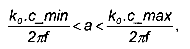
- where c_min is 115 m/s, c_max is 1970 m/s, f is the operating frequency and k0 is a constant (k0 = 3.83);
- wherein, in use, the lowest resonant frequency of radial fluid pressure oscillations in the cavity is greater than 500Hz; and
- wherein any unvalved apertures in the cavity walls are located at a distance of 0.63a plus or minus 0.2a from the centre of the cavity, where a is the cavity radius.
-

- Given the relationships between cavity radius and height above, the present invention provides a substantially disk-shaped cavity having a high aspect ratio.
- The invention can be thought of as an acoustic pump, in that an acoustic resonance is set up within the cavity. However, the driver velocity, typically of the order of 1ms-1, is amplified by the geometry of the cavity to give an effective drive velocity far exceeding this value, producing a very high acoustic pressure. Correspondingly, the high pressure may be seen as arising from the inertial reaction of the air (the air's resistance to motion) to the high acceleration imposed upon it by the combination of the actuator movement and the cavity geometry.
- An important difference between the present invention and known cylinder and conical pumps is the contribution of the resonance to the pressure in the cavity. Known cylinder and cone pumps rely on a high Q factor (strong resonance) to achieve high pressures, making them very sensitive to the tuning of the actuator and cavity resonances. However, the present invention operates at a much lower Q value and is therefore less sensitive to small shifts in resonance resulting from temperature fluctuations or changes in pump load.
- The present invention overcomes the large size of known linear resonance compressors by replacing the low frequency drive mechanism with a disk actuator, preferably piezoelectric. This disk is typically less than 1 mm thick and is tuned to operate at more than 500Hz, preferably 10kHz, more preferably 20kHz or higher. A frequency of approximately 20kHz or above provides operation above the threshold of normal human hearing, thereby removing the need for a noise enclosure. Preferably, in use, the frequency of the oscillatory motion is within 20% of the lowest resonant frequency of radial pressure oscillations in the cavity. More preferably, the frequency of the oscillatory motion is, in use, equal to the lowest resonant frequency of radial pressure oscillations in the cavity. Furthermore, the high frequency of the present invention significantly reduces the size of the cavity and the overall device. Accordingly, the present invention can be constructed with a cavity volume of less than 10ml, making it ideally suited to micro-device applications. A disk provides a low cavity volume and a geometric form able to sustain high amplitude pressure oscillations.
- It is preferable that the end walls defining the cavity are substantially planar and substantially parallel. However, the terms "substantially planar" and "substantially parallel" are intended to include frusto-conical surfaces such as those shown in
Figs. 5A and 5B as the change in separation of the two end walls over a typical diameter of 20mm is typically no more than 0.25mm. As such, the end walls are substantially planar and substantially parallel. - In a preferred example, the ratio of the cavity radius to its height is greater than 20, such that the cavity formed is a disk shape, similar to that of a coin or such like. By increasing the aspect ratio of the cavity, the acoustic pressure generated by the motion of the end wall(s) is significantly increased.
- In particular, when the cavity radius is greater than 1.2 times the height of the cavity, i.e.

- The body of the cavity is preferably less than 10ml and the lowest resonant frequency of the radial fluid pressure oscillations in the cavity is most preferably greater than 20kHz when the pump is in operation.
- One or both of the end walls that define the cavity may have a frusto-conical shape, such that the end walls are separated by a minimum distance at the centre and by maximum distance at the edge. The end walls are preferably circular, but may be any suitable shape having a radius.
- The perimeter of the end walls may be elliptical in shape.
- The actuator may be a piezoelectric device, a magnetostrictive device or may include a solenoid which, upon actuation drives a piston to drive one of the end walls of the cavity.
- Either one or both end walls are driven. In the example where both end walls are driven, it is preferable that the motion of the opposite walls is 180° out of phase. The motion of the driven walls is in a direction substantially perpendicular to the plane of the end walls.
- In use, the amplitude of the motion of the driven end wall(s) matches closely the profile of the pressure oscillation in the cavity. In this case, we describe the actuator and cavity as being mode-shape matched. For a disc shaped cavity, the profile of the pressure oscillation is approximately a Bessel function. Therefore the amplitude of the motion of the driven end wall(s) is at a maximum at the centre of the cavity. In this case the net volume swept by the cavity wall is much less than the cavity volume and so the pump has a low compression ratio.
- Any valved apertures which are provided in the cavity walls are preferably located near the centre of the end walls. It is not important whether the valved aperture is the inlet or the outlet, but it is essential that at least one of the apertures is controlled by a valve. The valved apertures should be located near the centre of the cavity, as this is the location of maximum pressure oscillation. It is understood that the term "valve" includes both traditional mechanical valves and asymmetric nozzle(s), designed such that their flow restriction in forward and reverse directions is substantially different.
- It is possible to combine two or more pumps, either in series or in parallel. It is also possible to combine two pumps such that they are separated by a common cavity end wall. Such a common end wall may be formed by actuator, in which case both pumps are powered by the same actuator.
- Examples of the present invention will now be described with reference to the accompanying drawings, in which:
-
Fig. 1 is a schematic vertical cross-section through one example according to the present invention; -
Figs. 2A to D show different arrangements of valved and unvalved apertures; -
Figs. 3A and 3B show displacement profiles of driven cavity end walls; -
Fig. 4 shows a pump having both upper and lower end walls driven; -
Figs. 5A and 5B show tapered cavities; -
Figs. 6A and 6B show a schematic and displacement profile of a two-cavity pump where the cavities share a common end wall; and -
Figs. 7A and 7B show different arrangements of valved and unvalved apertures for the two-cavity pump ofFigs 6A and 6B . -
Fig. 1 shows a schematic representation of apump 10 according to the present invention. Acavity 11 is defined byend walls side wall 14. The cavity is substantially circular in shape, although elliptical and other shapes could be used. Thecavity 11 is provided with anodal air inlet 15, which in this example is unvalved although, as shown inFigs. 2A to 2D , it could be valved and located substantially at the centre of theend wall 13. There is also avalved air outlet 16 located substantially at the centre ofend wall 13. Theupper end wall 12 is defined by the lower surface of adisc 17 attached to amain body 18. The inlet and outlet pass through themain body 18. - The actuator comprises a
piezoelectric disc 20 attached to adisc 17. Upon actuation, the actuator is caused to vibrate in a direction substantially perpendicular to the plane of the cavity, thereby generating radial pressure oscillations within the fluid in the cavity. The oscillation of the actuator is further described with regard toFigs. 3A, 3B and 4 . -
Figs. 2A to D show different arrangements of valved and unvalved apertures leading into and out ofcavity 11. InFig. 2A , twoinlet apertures 15 are unvalved and these are located at a point on a circle whose centre is the centre of theend wall 13 and whose radius is 0.63a. Avalved outlet 16 is located at the centre of theend wall 13. - In
Fig. 2B , both theinlet 15 andoutlet 16 apertures are valved and are located as close as possible to the centre of thelower end wall 13.Fig. 2D shows an example whereby thevalved inlet 15 andoutlet 16 apertures are located in the upper 12 and lower 13 end walls respectively such that they are both at the centre of the respective end wall. -
Fig. 2C shows an arrangement whereby the inlet aperture is valved and is located at the centre ofend wall 13 and two outlet apertures are provided at 0.63a away from the centre of theend wall 13 and are unvalved. -
Fig. 3A shows one possible displacement profile of the drivenwall 12 of the cavity. In this case the amplitude of motion is at a maximum at the centre of the cavity and at a minimum at its edge. The solid curved line and arrows indicate the wall displacement at one point in time and the dashed curved line its position one half cycle later. The displacements as drawn are exaggerated. -
Fig. 3B shows a preferable displacement profile of the drivenwall 12, namely a Bessel function having the following characteristics:
end wall 12 moves away from theopposite end wall 13, the outer portion of the drivenend wall 12 is caused to move towards theopposite end wall 13. In this case, the driven end wall and pressure oscillation in the cavity are mode-shape matched and the volume of thecavity 11 remains substantially constant. - In
Figs. 3A and 3B , only theupper end wall 12 is driven and the arrows show the oscillatory motion of thatend wall 12. InFig. 4 , the arrows indicate that both the upper 12 and lower 13 end walls are driven, such that their motion is 180° out of phase. -
Figs. 5A and 5B illustrate a tapered cavity in which one (Fig. 5A ) or both (Fig. 5B ) end walls are frusto-conical in shape. It will be seen how thecavity 11 has a greater height at the radial extremes, whereas at the centre, the distance between the end walls is at a minimum. Such a shape provides an increased pressure at the centre of the cavity. Typically, the diameter of the cavity is 20mm and h1 is 0.25mm and h2 is 0.5mm. As such, it will be appreciated how theend walls -
Fig. 6A shows a two-cavity pump in which the cavities share a common end-wall. In this case afirst cavity 21 is separated from asecond cavity 22 by anactuator 23. The first cavity is defined by end-wall 12 and side-wall 14, with the other end-wall being one surface ofactuator 23. The second cavity is defined by end-wall 13, side-wall 14, and the opposite surface ofactuator 23. In this arrangement both cavities are driven simultaneously by thesingle actuator 23.Fig 6B shows one possible displacement profile of theactuator 23. The positions of inlets and outlets have been omitted fromFigs. 6A and 6B for clarity. -
Figs 7A and 7B show different arrangements of valved and unvalved apertures leading into and out ofcavities Figs 6A and 6B . InFig. 7A , twopump inlet apertures 15 are provided at 0.63 times the radius ofcavity 22 away from the centre of theend wall 13 and are unvalved. Twopump outlet apertures 16 are provided at 0.63 times the radius ofcavity 21 away from the centre of theend wall 12 and are unvalved. Thecavities valved aperture 24 provided at the centre of theactuator 23. - In
Fig 7B avalved pump inlet 15 is provided at the centre of end-wall 13, and avalved pump outlet 16 is provided at the centre of end-wall 12. Thecavities unvalved apertures 25 provided at 0.63 times the radius ofcavities - The radius a of the
cavity 11 is related to the resonant operating frequency f by the following equation:
- For most fluids, 70ms-1 < a.f < 1200ms-1, corresponding to 115ms-1 < c < 1970 ms-1. In use, pressure oscillations within the cavity are driven by the piezoelectric actuator which causes oscillatory motion of one or both of the flat end walls. Either a pair of valves (inlet and outlet) or a single outlet valve and a nodal inlet aperture are used to generate a pumped flow.
- The choice of h and a determines the frequency of operation of the pump. The pressure generated is a function of the geometric amplification factor α, the resonant cavity Q-factor, the actuator velocity v, the density of the fluid ρ, and the speed of sound in the fluid c.
- The geometric amplification factor α is given by:

- Therefore, in order for the geometric amplification to be greater than 10,

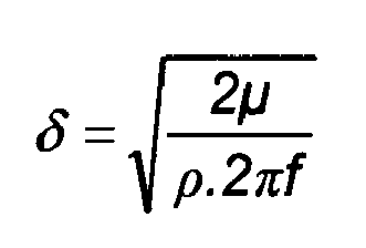
- The viscous boundary layer thickness δ is given by:

- With reference to
Fig. 1 , the displacement of the drivenwall 12 depends on the actuator velocity v and its frequency f, and must be less than the cavity thickness, giving:
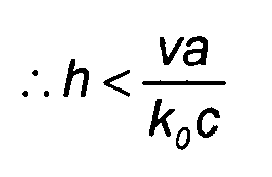
- In the case where both the upper and lower cavity walls are driven 180° out of phase, the maximum actuator displacement is half this value.
- Many applications require a small pump and therefore small cavity volume V:

- The following design criteria are important to the preferred values for optimum operation are as follows:
- cavity resonant frequency - preferably ≥ 500Hz,
- geometric amplification factor - preferably > 10,
- viscous boundary layer thickness - preferably less than half the cavity thickness,
- cavity wall displacement must be less than the cavity thickness, and cavity volume - preferably less than 1 cm3.
Claims (16)
- A fluid pump (10) comprising:one or more actuators (20);two end walls (12,13);a side wall (14);a cavity (11) which, in use, contains fluid, the cavity having a substantially cylindrical shape bounded by the end walls and the side walls;at least two apertures (15,16) through the cavity walls, at least one of which is a valved aperture (16);wherein the cavity radius, a, and height, h, satisfy the following inequalities:

 wherein, in use, the actuator (20) causes oscillatory motion of one or both end walls in a direction substantially perpendicular to the plane of the end walls (12,13);whereby, in use, the axial oscillations of the end walls (12,13) drive radial oscillations of fluid pressure in the cavity;wherein the cavity radius, a, also satisfies the following inequality:
 wherein, in use, the lowest resonant frequency of radial fluid pressure oscillations in the cavity is greater than 500Hz; andwherein any unvalved apertures in the cavity walls are located at a distance of 0.63a plus or minus 0.2a from the centre of the cavity (11), where a is the cavity radius.
 - A pump (10) according to claim 1, wherein the ratio

- A pump (10) according to either claim 1 or claim 2, wherein the volume of the cavity (11) is less than 10ml.
- A pump (10) according to claim 1, wherein, in use, the frequency of the oscillatory motion is equal to the lowest resonant frequency of radial pressure oscillations in the cavity.
- A pump (10) according to any one of the preceding claims, wherein one or both of the end walls (12,13) have a frusto-conical shape such that the end walls are separated by a minimum distance at the centre and by a maximum distance at the edge.
- A pump (10) according to any one of the preceding claims, wherein the actuator (20) is a piezoelectric device.
- A pump (10) according to any one of claims 1 to 5, wherein the actuator (20) is a magnetostrictive device.
- A pump (10) according to any one of claims 1 to 5, wherein the actuator (20) includes a solenoid.
- A pump (10) according to any one of the preceding claims, wherein the end wall motion is mode-shape matched to the pressure oscillation in the cavity (11).
- A pump (10) according to any one of the preceding claims, wherein the amplitude of end wall motion approximates the form of a Bessel function.
- A pump (10) according to any one of the preceding claims, wherein any valved apertures (16) in the cavity walls are located near the centre of the end walls (12,13).
- A pump (10) according to any one of claims 1 to 4, wherein the ratio

- A pair of pumps (10) according to any one of the preceding claims, wherein the two pump cavities (21,22) are separated by a common cavity end wall (23).
- A pair of pumps (10) according to claim 13, wherein the common cavity end wall is formed by an actuator.
- A pair of pumps (10) according to any one of claims 1 to 14, wherein the pumps are connected in series or in parallel.
- A fluid pump according to claim 1, wherein the or each valved aperture is a mechanical valve.
Applications Claiming Priority (2)
| Application Number | Priority Date | Filing Date | Title |
|---|---|---|---|
| GBGB0508194.8A GB0508194D0 (en) | 2005-04-22 | 2005-04-22 | Pump |
| PCT/GB2006/001487 WO2006111775A1 (en) | 2005-04-22 | 2006-04-21 | Pump |
Publications (2)
| Publication Number | Publication Date |
|---|---|
| EP1875081A1 EP1875081A1 (en) | 2008-01-09 |
| EP1875081B1 true EP1875081B1 (en) | 2013-12-25 |
Family
ID=34639978
Family Applications (1)
| Application Number | Title | Priority Date | Filing Date |
|---|---|---|---|
| EP06726876.3A Active EP1875081B1 (en) | 2005-04-22 | 2006-04-21 | Pump |
Country Status (6)
| Country | Link |
|---|---|
| US (1) | US8123502B2 (en) |
| EP (1) | EP1875081B1 (en) |
| JP (1) | JP4795428B2 (en) |
| CA (1) | CA2645907C (en) |
| GB (1) | GB0508194D0 (en) |
| WO (1) | WO2006111775A1 (en) |
Cited By (27)
| Publication number | Priority date | Publication date | Assignee | Title |
|---|---|---|---|---|
| US9427505B2 (en) | 2012-05-15 | 2016-08-30 | Smith & Nephew Plc | Negative pressure wound therapy apparatus |
| US10660994B2 (en) | 2012-03-12 | 2020-05-26 | Smith & Nephew Plc | Reduced pressure apparatus and methods |
| USD898925S1 (en) | 2018-09-13 | 2020-10-13 | Smith & Nephew Plc | Medical dressing |
| US10898388B2 (en) | 2015-04-27 | 2021-01-26 | Smith & Nephew Plc | Reduced pressure apparatuses and methods |
| US11096831B2 (en) | 2016-05-03 | 2021-08-24 | Smith & Nephew Plc | Negative pressure wound therapy device activation and control |
| US11110010B2 (en) | 2007-11-21 | 2021-09-07 | Smith & Nephew Plc | Wound dressing |
| US11116669B2 (en) | 2016-08-25 | 2021-09-14 | Smith & Nephew Plc | Absorbent negative pressure wound therapy dressing |
| US11123471B2 (en) | 2017-03-08 | 2021-09-21 | Smith & Nephew Plc | Negative pressure wound therapy device control in presence of fault condition |
| US11160915B2 (en) | 2017-05-09 | 2021-11-02 | Smith & Nephew Plc | Redundant controls for negative pressure wound therapy systems |
| US11173240B2 (en) | 2016-05-03 | 2021-11-16 | Smith & Nephew Plc | Optimizing power transfer to negative pressure sources in negative pressure therapy systems |
| US11285047B2 (en) | 2016-04-26 | 2022-03-29 | Smith & Nephew Plc | Wound dressings and methods of use with integrated negative pressure source having a fluid ingress inhibition component |
| US11305047B2 (en) | 2016-05-03 | 2022-04-19 | Smith & Nephew Plc | Systems and methods for driving negative pressure sources in negative pressure therapy systems |
| US11497653B2 (en) | 2017-11-01 | 2022-11-15 | Smith & Nephew Plc | Negative pressure wound treatment apparatuses and methods with integrated electronics |
| US11517656B2 (en) | 2006-05-11 | 2022-12-06 | Smith & Nephew, Inc. | Device and method for wound therapy |
| US11554203B2 (en) | 2017-11-01 | 2023-01-17 | Smith & Nephew Plc | Negative pressure wound treatment apparatuses and methods with integrated electronics |
| US11564847B2 (en) | 2016-09-30 | 2023-01-31 | Smith & Nephew Plc | Negative pressure wound treatment apparatuses and methods with integrated electronics |
| US11564845B2 (en) | 2017-09-13 | 2023-01-31 | Smith & Nephew Plc | Negative pressure wound treatment apparatuses and methods with integrated electronics |
| US11654228B2 (en) | 2014-12-22 | 2023-05-23 | Smith & Nephew Plc | Status indication for negative pressure wound therapy |
| US11701265B2 (en) | 2017-09-13 | 2023-07-18 | Smith & Nephew Plc | Negative pressure wound treatment apparatuses and methods with integrated electronics |
| US11707564B2 (en) | 2017-11-01 | 2023-07-25 | Smith & Nephew Plc | Safe operation of integrated negative pressure wound treatment apparatuses |
| US11723809B2 (en) | 2016-03-07 | 2023-08-15 | Smith & Nephew Plc | Wound treatment apparatuses and methods with negative pressure source integrated into wound dressing |
| US12005181B2 (en) | 2016-12-12 | 2024-06-11 | Smith & Nephew Plc | Pressure wound therapy status indication via external device |
| US12005182B2 (en) | 2019-05-31 | 2024-06-11 | T.J.Smith And Nephew, Limited | Systems and methods for extending operational time of negative pressure wound treatment apparatuses |
| EP3787806B1 (en) * | 2018-05-02 | 2024-06-26 | Ultrahaptics Ip Ltd | Blocking plate structure for improved acoustic transmission efficiency |
| US12083263B2 (en) | 2019-03-20 | 2024-09-10 | Smith & Nephew Plc | Negative pressure wound treatment apparatuses and methods with integrated electronics |
| US20240340576A1 (en) * | 2023-04-07 | 2024-10-10 | Sonicedge Ltd. | Ultrasonic Pump And Applications |
| US12447260B2 (en) | 2016-09-30 | 2025-10-21 | Smith & Nephew Plc | Negative pressure wound treatment apparatuses and methods with integrated electronics |
Families Citing this family (125)
| Publication number | Priority date | Publication date | Assignee | Title |
|---|---|---|---|---|
| GB0224986D0 (en) | 2002-10-28 | 2002-12-04 | Smith & Nephew | Apparatus |
| GB0325129D0 (en) | 2003-10-28 | 2003-12-03 | Smith & Nephew | Apparatus in situ |
| TWI308615B (en) * | 2006-06-20 | 2009-04-11 | Ind Tech Res Inst | Micro-pump and micro-pump system |
| DE602007004546D1 (en) | 2006-09-28 | 2010-03-18 | Tyco Healthcare | Portable wound therapy system |
| JP5407333B2 (en) * | 2007-01-23 | 2014-02-05 | 日本電気株式会社 | Diaphragm pump |
| US8485793B1 (en) * | 2007-09-14 | 2013-07-16 | Aprolase Development Co., Llc | Chip scale vacuum pump |
| DE102007050407A1 (en) | 2007-10-22 | 2009-04-23 | Fraunhofer-Gesellschaft zur Förderung der angewandten Forschung e.V. | Pump, pump assembly and pump module |
| EP3000448B2 (en) | 2007-11-21 | 2022-03-09 | Smith & Nephew PLC | Wound dressing |
| GB0723855D0 (en) | 2007-12-06 | 2008-01-16 | Smith & Nephew | Apparatus and method for wound volume measurement |
| KR101615395B1 (en) | 2008-03-05 | 2016-04-25 | 케이씨아이 라이센싱 인코포레이티드 | Dressing and method for applying reduced pressure to and collecting and storing fluid from a tissue site |
| GB0804739D0 (en) * | 2008-03-14 | 2008-04-16 | The Technology Partnership Plc | Pump |
| EP2312158B1 (en) * | 2008-06-05 | 2016-04-27 | Murata Manufacturing Co. Ltd. | Piezoelectric microblower |
| US9523358B2 (en) * | 2009-02-12 | 2016-12-20 | The Board Of Trustees Of The University Of Illinois | Magnetically driven micropump |
| AU2012244248B2 (en) * | 2009-02-12 | 2014-05-22 | The Board Of Trustees Of The University Of Illinois | Magnetically driven micropump |
| JP2012528980A (en) * | 2009-06-03 | 2012-11-15 | ザ テクノロジー パートナーシップ ピーエルシー | Fluid disc pump |
| CA2764334C (en) * | 2009-06-03 | 2016-11-22 | The Technology Partnership Plc | Pump with disc-shaped cavity |
| CN105909511B (en) * | 2009-06-03 | 2019-07-12 | Kci 医疗资源有限公司 | Pump with disc-shaped cavity |
| US8297947B2 (en) * | 2009-06-03 | 2012-10-30 | The Technology Partnership Plc | Fluid disc pump |
| US8821134B2 (en) * | 2009-06-03 | 2014-09-02 | The Technology Partnership Plc | Fluid disc pump |
| GB201001740D0 (en) | 2010-02-03 | 2010-03-24 | The Technology Partnership Plc | Disc pump and valve structure |
| US8371829B2 (en) * | 2010-02-03 | 2013-02-12 | Kci Licensing, Inc. | Fluid disc pump with square-wave driver |
| US8646479B2 (en) * | 2010-02-03 | 2014-02-11 | Kci Licensing, Inc. | Singulation of valves |
| US20120034109A1 (en) * | 2010-08-09 | 2012-02-09 | Aidan Marcus Tout | System and method for measuring pressure applied by a piezo-electric pump |
| GB201015656D0 (en) | 2010-09-20 | 2010-10-27 | Smith & Nephew | Pressure control apparatus |
| US20120109034A1 (en) | 2010-10-27 | 2012-05-03 | Kci Licensing, Inc. | Interactive, wireless reduced-pressure dressings, methods, and systems |
| GB201101870D0 (en) * | 2011-02-03 | 2011-03-23 | The Technology Partnership Plc | Pump |
| US9067003B2 (en) | 2011-05-26 | 2015-06-30 | Kalypto Medical, Inc. | Method for providing negative pressure to a negative pressure wound therapy bandage |
| US8974200B2 (en) * | 2011-07-08 | 2015-03-10 | International Business Machines Corporation | Device for creating fluid flow |
| JP5682513B2 (en) | 2011-09-06 | 2015-03-11 | 株式会社村田製作所 | Fluid control device |
| WO2013043300A1 (en) | 2011-09-21 | 2013-03-28 | Kci Licensing, Inc. | Dual -cavity pump |
| US9084845B2 (en) | 2011-11-02 | 2015-07-21 | Smith & Nephew Plc | Reduced pressure therapy apparatuses and methods of using same |
| US8790307B2 (en) | 2011-12-01 | 2014-07-29 | Picolife Technologies, Llc | Drug delivery device and methods therefor |
| US8771229B2 (en) | 2011-12-01 | 2014-07-08 | Picolife Technologies, Llc | Cartridge system for delivery of medicament |
| GB201120887D0 (en) | 2011-12-06 | 2012-01-18 | The Technology Partnership Plc | Acoustic sensor |
| EP2812577B1 (en) | 2012-02-10 | 2017-09-06 | KCI Licensing, Inc. | Systems and methods for monitoring a disc pump system using rfid |
| GB201202346D0 (en) | 2012-02-10 | 2012-03-28 | The Technology Partnership Plc | Disc pump with advanced actuator |
| AU2013216967A1 (en) | 2012-02-10 | 2014-08-28 | Kci Licensing, Inc. | Systems and methods for monitoring reduced pressure supplied by a disc pump system |
| CN104136777A (en) | 2012-02-10 | 2014-11-05 | 凯希特许有限公司 | Systems and methods for regulating the temperature of a disc pump system |
| WO2013119854A2 (en) | 2012-02-10 | 2013-08-15 | Kci Licensing, Inc. | Systems and methods for electrochemical detection in a disc pump |
| WO2013130255A1 (en) | 2012-02-29 | 2013-09-06 | Kci Licensing, Inc. | Systems and methods for supplying reduced pressure and measuring flow using a disc pump system |
| WO2013134056A1 (en) | 2012-03-07 | 2013-09-12 | Kci Licensing, Inc. | Disc pump with advanced actuator |
| US10130759B2 (en) | 2012-03-09 | 2018-11-20 | Picolife Technologies, Llc | Multi-ported drug delivery device having multi-reservoir cartridge system |
| RU2014138377A (en) | 2012-03-20 | 2016-05-20 | СМИТ ЭНД НЕФЬЮ ПиЭлСи | REDUCED PRESSURE THERAPY SYSTEM OPERATION MANAGEMENT BASED ON DETERMINING THE THRESHOLD THRESHOLD |
| US10286129B2 (en) | 2012-03-28 | 2019-05-14 | Kci Licensing, Inc. | Reduced-pressure systems, dressings, and methods facilitating separation of electronic and clinical component parts |
| US9883834B2 (en) | 2012-04-16 | 2018-02-06 | Farid Amirouche | Medication delivery device with multi-reservoir cartridge system and related methods of use |
| JP5928160B2 (en) | 2012-05-29 | 2016-06-01 | オムロンヘルスケア株式会社 | Piezoelectric pump and blood pressure information measuring apparatus including the same |
| US10245420B2 (en) | 2012-06-26 | 2019-04-02 | PicoLife Technologies | Medicament distribution systems and related methods of use |
| US9752565B2 (en) * | 2012-07-05 | 2017-09-05 | Kci Licensing, Inc. | Systems and methods for supplying reduced pressure using a disc pump with electrostatic actuation |
| WO2014008354A1 (en) | 2012-07-05 | 2014-01-09 | Kci Licensing, Inc. | Systems and methods for regulating the resonant frequency of a disc pump cavity |
| GB2513884B (en) | 2013-05-08 | 2015-06-17 | Univ Bristol | Method and apparatus for producing an acoustic field |
| GB201322103D0 (en) * | 2013-12-13 | 2014-01-29 | The Technology Partnership Plc | Fluid pump |
| US9612658B2 (en) | 2014-01-07 | 2017-04-04 | Ultrahaptics Ip Ltd | Method and apparatus for providing tactile sensations |
| DE112015000889B4 (en) | 2014-02-21 | 2023-04-20 | Murata Manufacturing Co., Ltd. | fan |
| GB2538413B (en) * | 2014-03-07 | 2020-08-05 | Murata Manufacturing Co | Blower |
| US20150314092A1 (en) * | 2014-04-30 | 2015-11-05 | Covidien Lp | Tracheal tube with controlled-pressure cuff |
| JP6065160B2 (en) | 2014-05-20 | 2017-01-25 | 株式会社村田製作所 | Blower |
| JP6332461B2 (en) | 2014-08-20 | 2018-05-30 | 株式会社村田製作所 | Blower |
| GB2530036A (en) | 2014-09-09 | 2016-03-16 | Ultrahaptics Ltd | Method and apparatus for modulating haptic feedback |
| JP6028779B2 (en) * | 2014-10-03 | 2016-11-16 | 株式会社村田製作所 | Fluid control device |
| EP3230727B1 (en) * | 2014-12-11 | 2024-08-21 | TTP plc | Acoustic sensor |
| JP6327368B2 (en) * | 2015-01-28 | 2018-05-23 | 株式会社村田製作所 | Valve, fluid control device |
| WO2016132144A1 (en) | 2015-02-20 | 2016-08-25 | Ultrahaptics Ip Limited | Perceptions in a haptic system |
| CA2976319C (en) | 2015-02-20 | 2023-06-27 | Ultrahaptics Ip Limited | Algorithm improvements in a haptic system |
| JP6319517B2 (en) | 2015-06-11 | 2018-05-09 | 株式会社村田製作所 | pump |
| US10818162B2 (en) | 2015-07-16 | 2020-10-27 | Ultrahaptics Ip Ltd | Calibration techniques in haptic systems |
| WO2017075321A1 (en) | 2015-10-30 | 2017-05-04 | Johnson & Johnson Consumer Inc. | Unit dose aseptic aerosol misting device |
| IL258628B (en) | 2015-10-30 | 2022-09-01 | Johnson & Johnson Consumer Inc | Install an uncontaminated spray misting device |
| JP6812428B2 (en) | 2015-10-30 | 2021-01-13 | ジョンソン・アンド・ジョンソン・コンシューマー・インコーポレイテッドJohnson & Johnson Consumer Inc. | Aseptic aerosol mist sprayer |
| CA3003438C (en) | 2015-10-30 | 2024-01-02 | Johnson & Johnson Consumer Inc. | Aseptic aerosol misting device |
| US11189140B2 (en) | 2016-01-05 | 2021-11-30 | Ultrahaptics Ip Ltd | Calibration and detection techniques in haptic systems |
| US10268275B2 (en) | 2016-08-03 | 2019-04-23 | Ultrahaptics Ip Ltd | Three-dimensional perceptions in haptic systems |
| DE102016009836A1 (en) * | 2016-08-15 | 2018-02-15 | Drägerwerk AG & Co. KGaA | Pneumatic control device |
| TWI602995B (en) * | 2016-09-05 | 2017-10-21 | 研能科技股份有限公司 | Fluid control device |
| TWI613367B (en) | 2016-09-05 | 2018-02-01 | 研能科技股份有限公司 | Fluid control device |
| TWI625468B (en) | 2016-09-05 | 2018-06-01 | 研能科技股份有限公司 | Fluid control device |
| US10634130B2 (en) | 2016-09-07 | 2020-04-28 | Sung Won Moon | Compact voice coil driven high flow fluid pumps and methods |
| US10943578B2 (en) | 2016-12-13 | 2021-03-09 | Ultrahaptics Ip Ltd | Driving techniques for phased-array systems |
| RU175857U1 (en) * | 2016-12-28 | 2017-12-21 | федеральное государственное бюджетное научное учреждение "Научно-исследовательский институт перспективных материалов и технологий" | Piezoelectric micropump |
| GB2579954B (en) | 2017-10-10 | 2022-08-10 | Murata Manufacturing Co | Pump and fluid control apparatus |
| US11531395B2 (en) | 2017-11-26 | 2022-12-20 | Ultrahaptics Ip Ltd | Haptic effects from focused acoustic fields |
| EP3729418B1 (en) | 2017-12-22 | 2024-11-20 | Ultrahaptics Ip Ltd | Minimizing unwanted responses in haptic systems |
| WO2019122912A1 (en) | 2017-12-22 | 2019-06-27 | Ultrahaptics Limited | Tracking in haptic systems |
| JP6769568B2 (en) * | 2017-12-26 | 2020-10-14 | 株式会社村田製作所 | Pump and fluid control |
| GB2582518B (en) * | 2018-01-10 | 2022-12-21 | Murata Manufacturing Co | Pump and fluid control device |
| WO2019138675A1 (en) * | 2018-01-10 | 2019-07-18 | 株式会社村田製作所 | Pump and fluid control device |
| US11554206B2 (en) | 2018-02-01 | 2023-01-17 | Kci Licensing, Inc. | Negative pressure wound therapy device using a vacuum generating pump providing audible therapy feedback |
| CN116221080A (en) * | 2018-05-31 | 2023-06-06 | 株式会社村田制作所 | Pump |
| GB2569417B (en) * | 2018-07-31 | 2020-06-17 | Ttp Ventus Ltd | Microfluidic drive system |
| US11098951B2 (en) | 2018-09-09 | 2021-08-24 | Ultrahaptics Ip Ltd | Ultrasonic-assisted liquid manipulation |
| GB2577710B (en) | 2018-10-03 | 2022-12-14 | Lee Ventus Ltd | Methods and devices for driving a piezoelectric pump |
| US11378997B2 (en) | 2018-10-12 | 2022-07-05 | Ultrahaptics Ip Ltd | Variable phase and frequency pulse-width modulation technique |
| WO2020111064A1 (en) * | 2018-11-27 | 2020-06-04 | 株式会社村田製作所 | Pump |
| GB2576796B (en) | 2018-12-07 | 2020-10-07 | Ttp Ventus Ltd | Improved valve |
| WO2020128426A1 (en) | 2018-12-07 | 2020-06-25 | Ttp Ventus Ltd. | Improved valve |
| US12373033B2 (en) | 2019-01-04 | 2025-07-29 | Ultrahaptics Ip Ltd | Mid-air haptic textures |
| WO2020141330A2 (en) | 2019-01-04 | 2020-07-09 | Ultrahaptics Ip Ltd | Mid-air haptic textures |
| US11842517B2 (en) | 2019-04-12 | 2023-12-12 | Ultrahaptics Ip Ltd | Using iterative 3D-model fitting for domain adaptation of a hand-pose-estimation neural network |
| WO2021049460A1 (en) * | 2019-09-11 | 2021-03-18 | 京セラ株式会社 | Piezoelectric pump and pump unit |
| WO2021074604A1 (en) | 2019-10-13 | 2021-04-22 | Ultraleap Limited | Dynamic capping with virtual microphones |
| US11374586B2 (en) | 2019-10-13 | 2022-06-28 | Ultraleap Limited | Reducing harmonic distortion by dithering |
| US11169610B2 (en) | 2019-11-08 | 2021-11-09 | Ultraleap Limited | Tracking techniques in haptic systems |
| US11715453B2 (en) | 2019-12-25 | 2023-08-01 | Ultraleap Limited | Acoustic transducer structures |
| GB2591468A (en) | 2020-01-28 | 2021-08-04 | Ttp Ventus Ltd | Valve for controlling a flow of a fluid |
| TWI720878B (en) * | 2020-04-24 | 2021-03-01 | 研能科技股份有限公司 | Actuating and sensing module |
| TWI720877B (en) * | 2020-04-24 | 2021-03-01 | 研能科技股份有限公司 | Actuating and sensing module |
| CN113551828B (en) * | 2020-04-24 | 2023-07-04 | 研能科技股份有限公司 | Actuation sensing module |
| US11816267B2 (en) | 2020-06-23 | 2023-11-14 | Ultraleap Limited | Features of airborne ultrasonic fields |
| GB2583880A (en) | 2020-07-31 | 2020-11-11 | Ttp Ventus Ltd | Actuator for a resonant acoustic pump |
| GB2597942B (en) | 2020-08-10 | 2022-08-03 | Ttp Ventus Ltd | Pump for microfluidic device |
| WO2022058738A1 (en) | 2020-09-17 | 2022-03-24 | Ultraleap Limited | Ultrahapticons |
| CN121322350A (en) * | 2020-09-30 | 2026-01-13 | 株式会社村田制作所 | Fluid control device |
| GB2606743B (en) | 2021-05-19 | 2023-12-27 | Lee Ventus Ltd | Microfluidic pump control |
| CN117581012A (en) * | 2021-06-24 | 2024-02-20 | 华为技术有限公司 | Thermoacoustically generated air flow device for electronic device cooling |
| US12517585B2 (en) | 2021-07-15 | 2026-01-06 | Ultraleap Limited | Control point manipulation techniques in haptic systems |
| GB2612629A (en) | 2021-11-08 | 2023-05-10 | Lee Ventus Ltd | Fluid control system |
| CN216847404U (en) * | 2022-01-12 | 2022-06-28 | 深圳市轩达电子有限公司 | Frequency-adjustable water dripping device |
| GB2619414A (en) * | 2022-01-12 | 2023-12-06 | Shenzhen Xuanda Electronics Co Ltd | Frequency-adjustable water dripping device |
| GB2616883A (en) | 2022-03-23 | 2023-09-27 | Lee Ventus Ltd | Improved valve |
| GB2622575B (en) | 2022-09-11 | 2025-01-08 | Bioliberty Ltd | Soft robotic assistive device |
| CN115822933A (en) * | 2022-12-23 | 2023-03-21 | 吉林大学 | A piezoelectric jet pump |
| GB2624475B (en) | 2023-02-08 | 2025-06-18 | Foster & Freeman Ltd | Volatile sampling device |
| CN117189554B (en) * | 2023-09-13 | 2024-05-28 | 深圳白边精密科技有限公司 | Acoustic pressure pump, working method and application equipment |
| WO2025190946A1 (en) | 2024-03-12 | 2025-09-18 | Bioliberty Ltd | Soft robotic assistive device |
| US12467448B1 (en) * | 2024-08-26 | 2025-11-11 | Shenzhen Baibian Precision Technology Co., Ltd. | Multi-vibrator connected piezoelectric pump, operating method and application device |
| CN118855669A (en) * | 2024-08-26 | 2024-10-29 | 深圳白边精密科技有限公司 | A multi-vibrator connected piezoelectric pump, working method and application equipment |
Citations (1)
| Publication number | Priority date | Publication date | Assignee | Title |
|---|---|---|---|---|
| WO1993010910A1 (en) * | 1991-12-04 | 1993-06-10 | The Technology Partnership Limited | Fluid droplet production apparatus and method |
Family Cites Families (8)
| Publication number | Priority date | Publication date | Assignee | Title |
|---|---|---|---|---|
| US5174130A (en) * | 1990-03-14 | 1992-12-29 | Sonic Compressor Systems, Inc. | Refrigeration system having standing wave compressor |
| SE508435C2 (en) * | 1993-02-23 | 1998-10-05 | Erik Stemme | Diaphragm pump type pump |
| US5769608A (en) * | 1994-06-10 | 1998-06-23 | P.D. Coop, Inc. | Resonant system to pump liquids, measure volume, and detect bubbles |
| DE4422743A1 (en) * | 1994-06-29 | 1996-01-04 | Torsten Gerlach | Micropump |
| DE19539020C2 (en) * | 1995-10-19 | 1999-04-22 | Siemens Ag | Pump for conveying gaseous or liquid media |
| US7198250B2 (en) * | 2000-09-18 | 2007-04-03 | Par Technologies, Llc | Piezoelectric actuator and pump using same |
| GB0308197D0 (en) * | 2003-04-09 | 2003-05-14 | The Technology Partnership Plc | Gas flow generator |
| CN100430599C (en) * | 2003-06-30 | 2008-11-05 | Nxp股份有限公司 | Devices for generating media flow |
-
2005
- 2005-04-22 GB GBGB0508194.8A patent/GB0508194D0/en not_active Ceased
-
2006
- 2006-04-21 JP JP2008507171A patent/JP4795428B2/en active Active
- 2006-04-21 WO PCT/GB2006/001487 patent/WO2006111775A1/en not_active Ceased
- 2006-04-21 CA CA2645907A patent/CA2645907C/en active Active
- 2006-04-21 EP EP06726876.3A patent/EP1875081B1/en active Active
- 2006-04-21 US US11/918,796 patent/US8123502B2/en active Active
Patent Citations (1)
| Publication number | Priority date | Publication date | Assignee | Title |
|---|---|---|---|---|
| WO1993010910A1 (en) * | 1991-12-04 | 1993-06-10 | The Technology Partnership Limited | Fluid droplet production apparatus and method |
Cited By (49)
| Publication number | Priority date | Publication date | Assignee | Title |
|---|---|---|---|---|
| US12128169B2 (en) | 2006-05-11 | 2024-10-29 | Smith & Nephew, Inc. | Device and method for wound therapy |
| US11813394B2 (en) | 2006-05-11 | 2023-11-14 | Smith & Nephew, Inc. | Device and method for wound therapy |
| US11517656B2 (en) | 2006-05-11 | 2022-12-06 | Smith & Nephew, Inc. | Device and method for wound therapy |
| US12290627B2 (en) | 2007-11-21 | 2025-05-06 | Smith & Nephew Plc | Wound dressing |
| US11110010B2 (en) | 2007-11-21 | 2021-09-07 | Smith & Nephew Plc | Wound dressing |
| US10660994B2 (en) | 2012-03-12 | 2020-05-26 | Smith & Nephew Plc | Reduced pressure apparatus and methods |
| US11903798B2 (en) | 2012-03-12 | 2024-02-20 | Smith & Nephew Plc | Reduced pressure apparatus and methods |
| US11129931B2 (en) | 2012-03-12 | 2021-09-28 | Smith & Nephew Plc | Reduced pressure apparatus and methods |
| US12186163B2 (en) | 2012-03-12 | 2025-01-07 | Smith & Nephew Plc | Reduced pressure apparatus and methods |
| US9427505B2 (en) | 2012-05-15 | 2016-08-30 | Smith & Nephew Plc | Negative pressure wound therapy apparatus |
| US10299964B2 (en) | 2012-05-15 | 2019-05-28 | Smith & Nephew Plc | Negative pressure wound therapy apparatus |
| US9545465B2 (en) | 2012-05-15 | 2017-01-17 | Smith & Newphew Plc | Negative pressure wound therapy apparatus |
| US11654228B2 (en) | 2014-12-22 | 2023-05-23 | Smith & Nephew Plc | Status indication for negative pressure wound therapy |
| US10898388B2 (en) | 2015-04-27 | 2021-01-26 | Smith & Nephew Plc | Reduced pressure apparatuses and methods |
| US12059325B2 (en) | 2015-04-27 | 2024-08-13 | Smith & Nephew Plc | Reduced pressure apparatuses and methods |
| US12396895B2 (en) | 2016-03-07 | 2025-08-26 | Smith & Nephew Plc | Wound treatment apparatuses and methods with negative pressure source integrated into wound dressing |
| US11723809B2 (en) | 2016-03-07 | 2023-08-15 | Smith & Nephew Plc | Wound treatment apparatuses and methods with negative pressure source integrated into wound dressing |
| US12121420B2 (en) | 2016-04-26 | 2024-10-22 | Smith & Nephew Plc | Wound dressings and methods of use with integrated negative pressure source having a fluid ingress inhibition component |
| US11285047B2 (en) | 2016-04-26 | 2022-03-29 | Smith & Nephew Plc | Wound dressings and methods of use with integrated negative pressure source having a fluid ingress inhibition component |
| US11173240B2 (en) | 2016-05-03 | 2021-11-16 | Smith & Nephew Plc | Optimizing power transfer to negative pressure sources in negative pressure therapy systems |
| US11896465B2 (en) | 2016-05-03 | 2024-02-13 | Smith & Nephew Plc | Negative pressure wound therapy device activation and control |
| US11096831B2 (en) | 2016-05-03 | 2021-08-24 | Smith & Nephew Plc | Negative pressure wound therapy device activation and control |
| US12268577B2 (en) | 2016-05-03 | 2025-04-08 | Smith & Nephew Plc | Optimizing power transfer to negative pressure sources in negative pressure therapy systems |
| US11305047B2 (en) | 2016-05-03 | 2022-04-19 | Smith & Nephew Plc | Systems and methods for driving negative pressure sources in negative pressure therapy systems |
| US11116669B2 (en) | 2016-08-25 | 2021-09-14 | Smith & Nephew Plc | Absorbent negative pressure wound therapy dressing |
| US11648152B2 (en) | 2016-08-25 | 2023-05-16 | Smith & Nephew Plc | Absorbent negative pressure wound therapy dressing |
| US12127919B2 (en) | 2016-09-30 | 2024-10-29 | Smith & Nephew Plc | Negative pressure wound treatment apparatuses and methods with integrated electronics |
| US12447260B2 (en) | 2016-09-30 | 2025-10-21 | Smith & Nephew Plc | Negative pressure wound treatment apparatuses and methods with integrated electronics |
| US11564847B2 (en) | 2016-09-30 | 2023-01-31 | Smith & Nephew Plc | Negative pressure wound treatment apparatuses and methods with integrated electronics |
| US12005181B2 (en) | 2016-12-12 | 2024-06-11 | Smith & Nephew Plc | Pressure wound therapy status indication via external device |
| US11123471B2 (en) | 2017-03-08 | 2021-09-21 | Smith & Nephew Plc | Negative pressure wound therapy device control in presence of fault condition |
| US11160915B2 (en) | 2017-05-09 | 2021-11-02 | Smith & Nephew Plc | Redundant controls for negative pressure wound therapy systems |
| US12447058B2 (en) | 2017-09-13 | 2025-10-21 | Smith & Nephew Plc | Negative pressure wound treatment apparatuses and methods with integrated electronics |
| US11564845B2 (en) | 2017-09-13 | 2023-01-31 | Smith & Nephew Plc | Negative pressure wound treatment apparatuses and methods with integrated electronics |
| US11701265B2 (en) | 2017-09-13 | 2023-07-18 | Smith & Nephew Plc | Negative pressure wound treatment apparatuses and methods with integrated electronics |
| US12097097B2 (en) | 2017-09-13 | 2024-09-24 | Smith & Nephew Plc | Negative pressure wound treatment apparatuses and methods with integrated electronics |
| US11707564B2 (en) | 2017-11-01 | 2023-07-25 | Smith & Nephew Plc | Safe operation of integrated negative pressure wound treatment apparatuses |
| US12128170B2 (en) | 2017-11-01 | 2024-10-29 | Smith & Nephew Plc | Negative pressure wound treatment apparatuses and methods with integrated electronics |
| US11554203B2 (en) | 2017-11-01 | 2023-01-17 | Smith & Nephew Plc | Negative pressure wound treatment apparatuses and methods with integrated electronics |
| US12324729B2 (en) | 2017-11-01 | 2025-06-10 | Smith & Nephew Plc | Negative pressure wound treatment apparatuses and methods with integrated electronics |
| US11992392B2 (en) | 2017-11-01 | 2024-05-28 | Smith & Nephew Plc | Negative pressure wound treatment apparatuses and methods with integrated electronics |
| US11497653B2 (en) | 2017-11-01 | 2022-11-15 | Smith & Nephew Plc | Negative pressure wound treatment apparatuses and methods with integrated electronics |
| EP4414556A3 (en) * | 2018-05-02 | 2024-10-23 | Ultrahaptics IP Limited | Blocking plate structure for improved acoustic transmission efficiency |
| EP3787806B1 (en) * | 2018-05-02 | 2024-06-26 | Ultrahaptics Ip Ltd | Blocking plate structure for improved acoustic transmission efficiency |
| USD999914S1 (en) | 2018-09-13 | 2023-09-26 | Smith & Nephew Plc | Medical dressing |
| USD898925S1 (en) | 2018-09-13 | 2020-10-13 | Smith & Nephew Plc | Medical dressing |
| US12083263B2 (en) | 2019-03-20 | 2024-09-10 | Smith & Nephew Plc | Negative pressure wound treatment apparatuses and methods with integrated electronics |
| US12005182B2 (en) | 2019-05-31 | 2024-06-11 | T.J.Smith And Nephew, Limited | Systems and methods for extending operational time of negative pressure wound treatment apparatuses |
| US20240340576A1 (en) * | 2023-04-07 | 2024-10-10 | Sonicedge Ltd. | Ultrasonic Pump And Applications |
Also Published As
| Publication number | Publication date |
|---|---|
| EP1875081A1 (en) | 2008-01-09 |
| US8123502B2 (en) | 2012-02-28 |
| US20090087323A1 (en) | 2009-04-02 |
| CA2645907A1 (en) | 2006-10-26 |
| GB0508194D0 (en) | 2005-06-01 |
| JP2008537057A (en) | 2008-09-11 |
| JP4795428B2 (en) | 2011-10-19 |
| CA2645907C (en) | 2011-08-09 |
| WO2006111775A1 (en) | 2006-10-26 |
Similar Documents
| Publication | Publication Date | Title |
|---|---|---|
| EP1875081B1 (en) | Pump | |
| CN102459899B (en) | Pumps with Disc Chamber | |
| EP2438301B1 (en) | Fluid disc pump | |
| US8297947B2 (en) | Fluid disc pump | |
| EP2758666B1 (en) | Dual-cavity pump | |
| US8821134B2 (en) | Fluid disc pump | |
| CN103814217B (en) | Dish pump and valve arrangement | |
| CN112081723B (en) | A piezoelectric pump based on resonance differential displacement amplification |
Legal Events
| Date | Code | Title | Description |
|---|---|---|---|
| PUAI | Public reference made under article 153(3) epc to a published international application that has entered the european phase |
Free format text: ORIGINAL CODE: 0009012 |
|
| 17P | Request for examination filed |
Effective date: 20071122 |
|
| AK | Designated contracting states |
Kind code of ref document: A1 Designated state(s): DE FR GB |
|
| DAX | Request for extension of the european patent (deleted) | ||
| RBV | Designated contracting states (corrected) |
Designated state(s): DE FR GB |
|
| 17Q | First examination report despatched |
Effective date: 20100708 |
|
| GRAP | Despatch of communication of intention to grant a patent |
Free format text: ORIGINAL CODE: EPIDOSNIGR1 |
|
| INTG | Intention to grant announced |
Effective date: 20130712 |
|
| RIN1 | Information on inventor provided before grant (corrected) |
Inventor name: BUCKLAND, JUSTIN RORKE Inventor name: BLAKEY, DAVID MARK Inventor name: SOMERVILLE, JOHN MATTHEW Inventor name: MCCRONE, JAMES EDWARD |
|
| GRAS | Grant fee paid |
Free format text: ORIGINAL CODE: EPIDOSNIGR3 |
|
| GRAA | (expected) grant |
Free format text: ORIGINAL CODE: 0009210 |
|
| AK | Designated contracting states |
Kind code of ref document: B1 Designated state(s): DE FR GB |
|
| REG | Reference to a national code |
Ref country code: GB Ref legal event code: FG4D |
|
| REG | Reference to a national code |
Ref country code: DE Ref legal event code: R096 Ref document number: 602006039776 Country of ref document: DE Effective date: 20140213 |
|
| REG | Reference to a national code |
Ref country code: DE Ref legal event code: R097 Ref document number: 602006039776 Country of ref document: DE |
|
| PLBE | No opposition filed within time limit |
Free format text: ORIGINAL CODE: 0009261 |
|
| STAA | Information on the status of an ep patent application or granted ep patent |
Free format text: STATUS: NO OPPOSITION FILED WITHIN TIME LIMIT |
|
| 26N | No opposition filed |
Effective date: 20140926 |
|
| REG | Reference to a national code |
Ref country code: DE Ref legal event code: R097 Ref document number: 602006039776 Country of ref document: DE Effective date: 20140926 |
|
| REG | Reference to a national code |
Ref country code: FR Ref legal event code: PLFP Year of fee payment: 11 |
|
| REG | Reference to a national code |
Ref country code: FR Ref legal event code: PLFP Year of fee payment: 12 |
|
| REG | Reference to a national code |
Ref country code: FR Ref legal event code: PLFP Year of fee payment: 13 |
|
| REG | Reference to a national code |
Ref country code: DE Ref legal event code: R081 Ref document number: 602006039776 Country of ref document: DE Owner name: TTP VENTUS LIMITED, ROYSTON, GB Free format text: FORMER OWNER: THE TECHNOLOGY PARTNERSHIP PLC, MELBOURN, ROYSTON, HERTFORDSHIRE, GB |
|
| REG | Reference to a national code |
Ref country code: GB Ref legal event code: 732E Free format text: REGISTERED BETWEEN 20210715 AND 20210721 |
|
| P01 | Opt-out of the competence of the unified patent court (upc) registered |
Effective date: 20230523 |
|
| PGFP | Annual fee paid to national office [announced via postgrant information from national office to epo] |
Ref country code: FR Payment date: 20250310 Year of fee payment: 20 |
|
| PGFP | Annual fee paid to national office [announced via postgrant information from national office to epo] |
Ref country code: GB Payment date: 20250306 Year of fee payment: 20 |
|
| PGFP | Annual fee paid to national office [announced via postgrant information from national office to epo] |
Ref country code: DE Payment date: 20250305 Year of fee payment: 20 |