DE102006031326B4 - Mold core and method for producing a fiber composite component for the aerospace industry - Google Patents
Mold core and method for producing a fiber composite component for the aerospace industry Download PDFInfo
- Publication number
- DE102006031326B4 DE102006031326B4 DE102006031326A DE102006031326A DE102006031326B4 DE 102006031326 B4 DE102006031326 B4 DE 102006031326B4 DE 102006031326 A DE102006031326 A DE 102006031326A DE 102006031326 A DE102006031326 A DE 102006031326A DE 102006031326 B4 DE102006031326 B4 DE 102006031326B4
- Authority
- DE
- Germany
- Prior art keywords
- mold core
- mandrel
- hollow profile
- fiber composite
- composite component
- Prior art date
- Legal status (The legal status is an assumption and is not a legal conclusion. Google has not performed a legal analysis and makes no representation as to the accuracy of the status listed.)
- Expired - Fee Related
Links
- 239000000835 fiber Substances 0.000 claims abstract description 63
- 239000002131 composite material Substances 0.000 claims abstract description 45
- 238000000034 method Methods 0.000 claims description 36
- 239000011248 coating agent Substances 0.000 claims description 19
- 238000000576 coating method Methods 0.000 claims description 19
- 238000004519 manufacturing process Methods 0.000 claims description 18
- 239000004033 plastic Substances 0.000 claims description 17
- 239000000463 material Substances 0.000 claims description 16
- 210000000633 nuclear envelope Anatomy 0.000 claims description 16
- 230000008569 process Effects 0.000 claims description 12
- 239000000047 product Substances 0.000 claims description 11
- 239000012744 reinforcing agent Substances 0.000 claims description 7
- 238000004804 winding Methods 0.000 claims description 7
- 238000009499 grossing Methods 0.000 claims description 6
- 239000011159 matrix material Substances 0.000 claims description 5
- 238000000465 moulding Methods 0.000 claims description 5
- 239000003973 paint Substances 0.000 claims description 5
- 239000004593 Epoxy Substances 0.000 claims description 3
- 229910000831 Steel Inorganic materials 0.000 claims description 3
- 239000011258 core-shell material Substances 0.000 claims description 3
- 238000010438 heat treatment Methods 0.000 claims description 3
- 239000002184 metal Substances 0.000 claims description 3
- 238000007493 shaping process Methods 0.000 claims description 3
- 239000010959 steel Substances 0.000 claims description 3
- 230000007704 transition Effects 0.000 claims description 3
- 239000004952 Polyamide Substances 0.000 claims description 2
- 229920002647 polyamide Polymers 0.000 claims description 2
- 239000004810 polytetrafluoroethylene Substances 0.000 claims description 2
- 229920001343 polytetrafluoroethylene Polymers 0.000 claims description 2
- 230000003014 reinforcing effect Effects 0.000 claims description 2
- 239000011265 semifinished product Substances 0.000 claims description 2
- 238000000151 deposition Methods 0.000 claims 3
- 230000003321 amplification Effects 0.000 claims 1
- 230000015572 biosynthetic process Effects 0.000 claims 1
- 229920001971 elastomer Polymers 0.000 claims 1
- 239000000806 elastomer Substances 0.000 claims 1
- 238000003475 lamination Methods 0.000 claims 1
- 238000003199 nucleic acid amplification method Methods 0.000 claims 1
- 238000001721 transfer moulding Methods 0.000 claims 1
- 238000009755 vacuum infusion Methods 0.000 claims 1
- 239000011162 core material Substances 0.000 description 40
- 239000000306 component Substances 0.000 description 33
- 230000008901 benefit Effects 0.000 description 6
- 239000003822 epoxy resin Substances 0.000 description 4
- 229920000647 polyepoxide Polymers 0.000 description 4
- 238000001802 infusion Methods 0.000 description 3
- 238000000605 extraction Methods 0.000 description 2
- 239000000945 filler Substances 0.000 description 2
- 238000010137 moulding (plastic) Methods 0.000 description 2
- 230000008719 thickening Effects 0.000 description 2
- 229920000049 Carbon (fiber) Polymers 0.000 description 1
- 206010040844 Skin exfoliation Diseases 0.000 description 1
- 230000009471 action Effects 0.000 description 1
- 238000000137 annealing Methods 0.000 description 1
- 238000013459 approach Methods 0.000 description 1
- 238000005452 bending Methods 0.000 description 1
- 230000009286 beneficial effect Effects 0.000 description 1
- 239000004917 carbon fiber Substances 0.000 description 1
- 150000001875 compounds Chemical class 0.000 description 1
- 238000010276 construction Methods 0.000 description 1
- 239000008358 core component Substances 0.000 description 1
- 230000001419 dependent effect Effects 0.000 description 1
- 238000007598 dipping method Methods 0.000 description 1
- 230000008595 infiltration Effects 0.000 description 1
- 238000001764 infiltration Methods 0.000 description 1
- 239000004922 lacquer Substances 0.000 description 1
- VNWKTOKETHGBQD-UHFFFAOYSA-N methane Chemical compound C VNWKTOKETHGBQD-UHFFFAOYSA-N 0.000 description 1
- 230000035515 penetration Effects 0.000 description 1
- 230000009467 reduction Effects 0.000 description 1
- 238000000926 separation method Methods 0.000 description 1
- 230000006641 stabilisation Effects 0.000 description 1
- 238000011105 stabilization Methods 0.000 description 1
- 230000000087 stabilizing effect Effects 0.000 description 1
- 210000001519 tissue Anatomy 0.000 description 1
Classifications
-
- B—PERFORMING OPERATIONS; TRANSPORTING
- B29—WORKING OF PLASTICS; WORKING OF SUBSTANCES IN A PLASTIC STATE IN GENERAL
- B29C—SHAPING OR JOINING OF PLASTICS; SHAPING OF MATERIAL IN A PLASTIC STATE, NOT OTHERWISE PROVIDED FOR; AFTER-TREATMENT OF THE SHAPED PRODUCTS, e.g. REPAIRING
- B29C70/00—Shaping composites, i.e. plastics material comprising reinforcements, fillers or preformed parts, e.g. inserts
- B29C70/04—Shaping composites, i.e. plastics material comprising reinforcements, fillers or preformed parts, e.g. inserts comprising reinforcements only, e.g. self-reinforcing plastics
- B29C70/28—Shaping operations therefor
- B29C70/30—Shaping by lay-up, i.e. applying fibres, tape or broadsheet on a mould, former or core; Shaping by spray-up, i.e. spraying of fibres on a mould, former or core
-
- B—PERFORMING OPERATIONS; TRANSPORTING
- B29—WORKING OF PLASTICS; WORKING OF SUBSTANCES IN A PLASTIC STATE IN GENERAL
- B29C—SHAPING OR JOINING OF PLASTICS; SHAPING OF MATERIAL IN A PLASTIC STATE, NOT OTHERWISE PROVIDED FOR; AFTER-TREATMENT OF THE SHAPED PRODUCTS, e.g. REPAIRING
- B29C33/00—Moulds or cores; Details thereof or accessories therefor
- B29C33/44—Moulds or cores; Details thereof or accessories therefor with means for, or specially constructed to facilitate, the removal of articles, e.g. of undercut articles
- B29C33/48—Moulds or cores; Details thereof or accessories therefor with means for, or specially constructed to facilitate, the removal of articles, e.g. of undercut articles with means for collapsing or disassembling
- B29C33/485—Moulds or cores; Details thereof or accessories therefor with means for, or specially constructed to facilitate, the removal of articles, e.g. of undercut articles with means for collapsing or disassembling cores or mandrels
-
- B—PERFORMING OPERATIONS; TRANSPORTING
- B29—WORKING OF PLASTICS; WORKING OF SUBSTANCES IN A PLASTIC STATE IN GENERAL
- B29C—SHAPING OR JOINING OF PLASTICS; SHAPING OF MATERIAL IN A PLASTIC STATE, NOT OTHERWISE PROVIDED FOR; AFTER-TREATMENT OF THE SHAPED PRODUCTS, e.g. REPAIRING
- B29C33/00—Moulds or cores; Details thereof or accessories therefor
- B29C33/76—Cores
-
- B—PERFORMING OPERATIONS; TRANSPORTING
- B29—WORKING OF PLASTICS; WORKING OF SUBSTANCES IN A PLASTIC STATE IN GENERAL
- B29C—SHAPING OR JOINING OF PLASTICS; SHAPING OF MATERIAL IN A PLASTIC STATE, NOT OTHERWISE PROVIDED FOR; AFTER-TREATMENT OF THE SHAPED PRODUCTS, e.g. REPAIRING
- B29C70/00—Shaping composites, i.e. plastics material comprising reinforcements, fillers or preformed parts, e.g. inserts
- B29C70/04—Shaping composites, i.e. plastics material comprising reinforcements, fillers or preformed parts, e.g. inserts comprising reinforcements only, e.g. self-reinforcing plastics
- B29C70/28—Shaping operations therefor
- B29C70/40—Shaping or impregnating by compression not applied
- B29C70/42—Shaping or impregnating by compression not applied for producing articles of definite length, i.e. discrete articles
- B29C70/44—Shaping or impregnating by compression not applied for producing articles of definite length, i.e. discrete articles using isostatic pressure, e.g. pressure difference-moulding, vacuum bag-moulding, autoclave-moulding or expanding rubber-moulding
- B29C70/443—Shaping or impregnating by compression not applied for producing articles of definite length, i.e. discrete articles using isostatic pressure, e.g. pressure difference-moulding, vacuum bag-moulding, autoclave-moulding or expanding rubber-moulding and impregnating by vacuum or injection
-
- B—PERFORMING OPERATIONS; TRANSPORTING
- B29—WORKING OF PLASTICS; WORKING OF SUBSTANCES IN A PLASTIC STATE IN GENERAL
- B29C—SHAPING OR JOINING OF PLASTICS; SHAPING OF MATERIAL IN A PLASTIC STATE, NOT OTHERWISE PROVIDED FOR; AFTER-TREATMENT OF THE SHAPED PRODUCTS, e.g. REPAIRING
- B29C70/00—Shaping composites, i.e. plastics material comprising reinforcements, fillers or preformed parts, e.g. inserts
- B29C70/04—Shaping composites, i.e. plastics material comprising reinforcements, fillers or preformed parts, e.g. inserts comprising reinforcements only, e.g. self-reinforcing plastics
- B29C70/28—Shaping operations therefor
- B29C70/40—Shaping or impregnating by compression not applied
- B29C70/42—Shaping or impregnating by compression not applied for producing articles of definite length, i.e. discrete articles
- B29C70/46—Shaping or impregnating by compression not applied for producing articles of definite length, i.e. discrete articles using matched moulds, e.g. for deforming sheet moulding compounds [SMC] or prepregs
- B29C70/48—Shaping or impregnating by compression not applied for producing articles of definite length, i.e. discrete articles using matched moulds, e.g. for deforming sheet moulding compounds [SMC] or prepregs and impregnating the reinforcements in the closed mould, e.g. resin transfer moulding [RTM], e.g. by vacuum
-
- B—PERFORMING OPERATIONS; TRANSPORTING
- B29—WORKING OF PLASTICS; WORKING OF SUBSTANCES IN A PLASTIC STATE IN GENERAL
- B29D—PRODUCING PARTICULAR ARTICLES FROM PLASTICS OR FROM SUBSTANCES IN A PLASTIC STATE
- B29D99/00—Subject matter not provided for in other groups of this subclass
- B29D99/001—Producing wall or panel-like structures, e.g. for hulls, fuselages, or buildings
- B29D99/0014—Producing wall or panel-like structures, e.g. for hulls, fuselages, or buildings provided with ridges or ribs, e.g. joined ribs
-
- Y—GENERAL TAGGING OF NEW TECHNOLOGICAL DEVELOPMENTS; GENERAL TAGGING OF CROSS-SECTIONAL TECHNOLOGIES SPANNING OVER SEVERAL SECTIONS OF THE IPC; TECHNICAL SUBJECTS COVERED BY FORMER USPC CROSS-REFERENCE ART COLLECTIONS [XRACs] AND DIGESTS
- Y02—TECHNOLOGIES OR APPLICATIONS FOR MITIGATION OR ADAPTATION AGAINST CLIMATE CHANGE
- Y02T—CLIMATE CHANGE MITIGATION TECHNOLOGIES RELATED TO TRANSPORTATION
- Y02T50/00—Aeronautics or air transport
- Y02T50/40—Weight reduction
Landscapes
- Engineering & Computer Science (AREA)
- Mechanical Engineering (AREA)
- Chemical & Material Sciences (AREA)
- Composite Materials (AREA)
- Architecture (AREA)
- Civil Engineering (AREA)
- Structural Engineering (AREA)
- Moulding By Coating Moulds (AREA)
Abstract
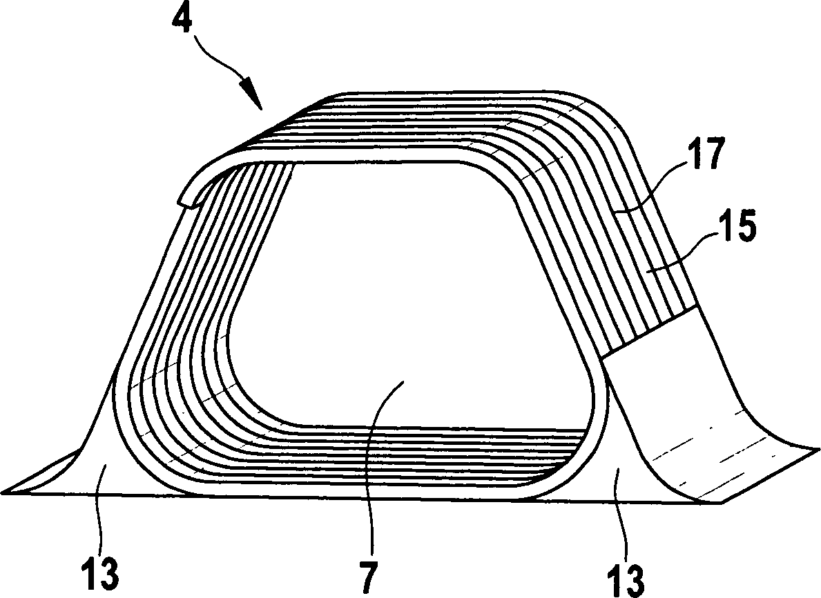
Formkern (4) zur Herstellung eines Faserverbundbauteils (1), insbesondere eines Stringers (12) an einem Basisbauteil (2) in der Luft- und Raumfahrt, mit einem spiralförmigen Aufbau,
dadurch gekennzeichnet,
dass der Formkern (4) ausschließlich aus einem Hohlprofil (15, 16) mit einer an den Formkern (4) angepassten äußeren Geometrie und mit einem in die Wand des Hohlprofils (15, 16) eingebrachten, spiralförmig umlaufenden Schlitz (17) besteht; und
dass das geschlitzte Hohlprofil (15, 16) mit einer Lagefixierung versehen ist.Mold core (4) for producing a fiber composite component (1), in particular a stringer (12) on a base component (2) in aerospace, with a spiral structure,
characterized,
that the mandrel (4) consists exclusively of a hollow profile (15, 16) with an outer geometry adapted to the mandrel (4) and with a spiral-shaped slot (17) introduced into the wall of the hollow profile (15, 16); and
the slotted hollow profile (15, 16) is provided with a positional fixation.
Description
Die vorliegende Erfindung bezieht sich auf einen Formkern zur Herstellung eines Faserverbundbauteils, auf ein Verfahren zur Herstellung eines Faserverbundteils, insbesondere für die Luft- und Raumluft und auf ein Faserverbundbauteil mit wenigstens einem Stringer, welches mittels eines solchen Formkerns und/oder eines solchen Verfahrens hergestellt ist.The The present invention relates to a mold core for manufacturing a fiber composite component, a method for producing a Fiber composite part, in particular for the air and room air and to a fiber composite component with at least one stringer, which produced by means of such a mold core and / or such a method is.
Obwohl auf beliebige Faserverbundbauteile anwendbar, werden die vorliegende Erfindung sowie die ihr zugrunde liegende Problematik nachfolgend mit Bezug auf flächige, stringerversteifte Kohlefaserkunststoff(CFK)-Bauteile, beispielsweise Hautschalen eines Flugszeugs, näher erläutert.Even though Applicable to any fiber composite components, the present Invention and the underlying problem with below Terms of area, Stringerversteifte carbon fiber plastic (CFRP) components, for example Skin shells of an aircraft, closer explained.
Es ist allgemein bekannt, CFK-Hautschalen mit CFK-Stringern zu versteifen, um den hohen Belastungen im Flugzeugbereich bei möglichst geringem zusätzlichen Gewicht standzuhalten. Dabei werden im Wesentlichen zwei Arten von Stringern unterschieden: T- und Ω-Stringer.It It is well known to stiffen CFRP skin shells with CFRP stringers to keep the high Burdens in the aircraft sector with the least possible additional To withstand weight. There are essentially two types of Stringers differ: T and Ω stringers.
Der Querschnitt von T-Stringern setzt sich aus der Basis und dem Steg zusammen. Die Basis bildet die Verbindungsfläche zur Hautschale. Die Verwendung von T-Stringer versteiften Hautschalen ist im Flugzeugbau weit verbreitet.Of the Cross section of T-stringers is made up of the base and the bridge together. The base forms the connection surface to the skin shell. The usage stiffened by T-Stringer Skin shells are widely used in aircraft construction.
Ω-Stringer weisen in etwa ein Hutprofil auf, wobei dessen Enden mit der Hautschale verbunden sind. Ω-Stringer können entweder im ausgehärteten Zustand auf die ebenfalls ausgehärtete Schale geklebt, oder gleichzeitig mit der Schale Nass-in-Nass ausgehärtet werden. Letzteres wird angestrebt, weil dies prozesstechnisch günstiger ist. Zur Nass-in-Nass-Herstellung von mit Ω-Stringer versteiften Hautschalen sind jedoch Stütz- bzw. Formkerne notwendig, um die formlabilen Faserhalbzeuge während des Herstellungsprozesses in der gewünschten Ω-Form zu fixieren und abzustützen. Hautschalen mit Ω-Stringern weisen gegenüber T-Stringern den Vorteil einer besseren Infiltrierbarkeit während eines Infusionsverfahrens zum Einbringen einer Matrix, beispielsweise eines Epoxidharzes, in die Faserhalbzeuge auf. Infusionsverfahren können gegenüber anderen bekannten Verfahren zur Herstellung von Faserverbundbauteilen, wie beispielsweise dem Prepreg-Verfahren, kostengünstig, weil dies die Verwendung von kostengünstigeren Faserhalbzeugen erlaubt.Ω-stringer have approximately a hat profile, with its ends with the skin shell are connected. Ω-stringer can either in the cured state on the likewise hardened Glued shell, or cured simultaneously with the shell wet-on-wet. The latter is sought, because this process is cheaper is. For wet-on-wet production of Ω-Stringer stiffened skin shells However, or mandrels necessary to form-labile semi-finished fiber during the Manufacturing process in the desired Ω-shape too fix and support. skin peeling with Ω-stringers show respect to T-stringers the advantage of better infiltration during an infusion procedure for introducing a matrix, for example an epoxy resin, in the semi-finished fiber products. Infusion methods may be over other known methods for the production of fiber composite components, such as the Prepreg process, inexpensive, because this allows the use of cheaper semi-finished fiber.
Es besteht jedoch bei der Herstellung von Ω-Stringern das Problem, dass das gegenwärtig für den Stütz- bzw. Formkern verwendete Material kostenintensiv ist und nach dem Ausbilden der Ω-Stringer nur schwierig entfernt werden kann, so dass das in den Stringern verbleibende Material zu dem Gesamtgewicht des Flugzeugs nachteilig beiträgt.It However, there is the problem in the production of Ω-stringers that the present for the supporting or mold core used material is costly and after the Forming the Ω stringer only difficult to remove, so that in the stringers remaining material to the total weight of the aircraft disadvantageous contributes.
Die
Vor diesem Hintergrund liegt der vorliegenden Erfindung die Aufgabe zugrunde, ein kostengünstigeres und leichteres Faserverbundbauteil, insbesondere für die Luft- und Raumfahrt, bereitzustellen.In front In this background, the present invention has the object underlying, a cheaper and lighter fiber composite component, in particular for the air and space.
Erfindungsgemäß wird diese Aufgabe durch einen Formkern mit den Merkmalen des Patentanspruchs 1, ein Verfahren mit den Merkmalen des Patentanspruchs 16 und/oder durch ein Faserverbundbauteil mit den Merkmalen des Patentanspruchs 31 gelöst.According to the invention this Task by a mold core with the features of the claim 1, a method with the features of claim 16 and / or by a fiber composite component with the features of the claim 31 solved.
Die vorliegende Erfindung weist gegenüber den eingangs genannten Ansätzen den Vorteil auf, dass das Faserverbundbauteil mittels eines kostengünstigen Formkerns herstellbar ist. Anstelle von kostenintensiven herkömmlichen Materialien wird vorteilhaft ein Formkern mit einem Spiralaufbau verwendet, der in vorteilhaft einfacher Weise entformbar ist, was Gewichtsvorteile gegenüber herkömmlichen, verbleibenden Materialien mit sich bringt.The present invention has over the aforementioned approaches the advantage that the fiber composite component by means of a cost-effective Mold core is produced. Instead of costly conventional Materials will be advantageous a mold core with a spiral structure used, which is demoldable in an advantageous simple manner, what Compared to weight advantages conventional, remaining Materials.
Wird das Hohlprofil vollständig geschlitzt, wird es nachträglich mit einer Lagefixierung, beispielsweise mit einer Lackbeschichtung beispielsweise in einem Tauchbad, versehen. Dies kann auch bei einem nicht geschlitzten Hohlprofil erfolgen. Ein solches Hohlprofil kann leicht aus Kunststoff in einem Formwerkzeug hergestellt werden. Vorteilhaft dabei ist durch das Einbringen eines umlaufenden Schlitzes, dass zum Entformen das Hohlprofil in einfacher Weise an einem Ende erfasst und aus dem Formabschnitt herausgezogen wird, wobei kein Kernbauteil mehr im Formabschnitt verbleibt. Dabei reißt das Hohlprofil umlaufend und schält sich durch die Zugkraft von der Kernhülle ab. Becomes the hollow profile completely slotted, it is retrospective with a position fixation, for example with a lacquer coating for example, in a dipping bath provided. This can also be done at one not slotted hollow profile done. Such a hollow profile can easily made of plastic in a mold. An advantage here is the introduction of a circumferential slot, that for demolding the hollow profile in a simple manner at one end is detected and pulled out of the mold section, wherein no core component more remains in the mold section. The hollow profile rips circumferentially and peels by the tensile force of the nuclear envelope from.
In den Unteransprüchen finden sich vorteilhafte Ausgestaltungen und Verbesserungen der vorliegenden Erfindung.In the dependent claims find advantageous embodiments and improvements of present invention.
In bevorzugter Ausgestaltung ist vorgesehen, dass beim Ausbilden des Formkerns ein Hohlprofil, welches die äußere Geometrie des Formkerns aufweist, mit einem in die Wand des Hohlprofils eingebrachten, spiralförmig umlaufenden Schlitz versehen wird, welcher die Wand des Hohlprofils oder mit Ausnahme von zumindest drei am Umfang der Wand des Hohlprofils verteilt angeordneten Stellen vollständig durchdringt. Die nicht vollständig durchdrungenen Stellen dienen als Sollbruchstellen beim Entformen des Formkerns und zur Stabilisierung des Hohlprofils.In a preferred embodiment, it is provided that, when forming the mandrel, a hollow profile, which the outer geometry of the mandrel has, provided with a introduced into the wall of the hollow profile, a spiral circumferential slot which completely penetrates the wall of the hollow profile or with the exception of at least three distributed on the circumference of the wall of the hollow profile arranged points. The not fully penetrated points serve as predetermined breaking points during demoulding of the mandrel and for stabilizing the hollow profile.
In alternativer Ausführung wird der Formkern aus einem Draht, vorzugsweise Stahldraht spiralförmig mit der Kontur des Formkerns gewickelt. Zur Beibehaltung der Form und zum Verhindern einer Rückfederung kann der Draht einer Wärmebehandlung unterzogen werden. Daraus ergibt sich vorteilhaft, dass der Draht des Formkerns beim Entformen aufgewickelt wird und wieder verwendet oder recycled werden kann.In alternative version is the mandrel made of a wire, preferably steel wire spiral wrapped the contour of the mandrel. To maintain the shape and to prevent springback The wire can be subjected to a heat treatment become. This results in advantageous that the wire of the mandrel is wound up during demolding and reused or recycled can.
Dabei kann der spiralförmige Formkern mit einer äußeren Beschichtung, zum Beispiel ein spröder mit Füllstoffen versetzter Kunststoff, ein gefülltes Epoxidharz oder ein leichtspachtelähnlicher Werkstoff, zum Ausglätten einer Rippung des Metalldrahts versehen werden, wodurch sich glatte Oberflächen und eine gute Entformbarkeit ergeben. Hierzu kann auch zusätzlich eine Kernhülle, zum Beispiel ein Schlauch, verwendet werden, die den Formkern vollständig umgibt. Hierdurch ergibt sich ebenfalls eine vorteilhaft leichte Entformbarkeit ohne den hergestellten Formabschnitt beim Entformen zu beschädigen.there may be the spiral Mold core with an outer coating, for example a brittle one with fillers staggered plastic, a filled epoxy resin or a light filler-like Material for smoothing be provided a ribbing of the metal wire, resulting in smooth Surfaces and give a good mold release. This can also be an additional Nuclear envelope, For example, a tube can be used which completely surrounds the mandrel. This also results in an advantageous easy removability without damaging the manufactured mold section during demolding.
Gemäß einer bevorzugten Ausführungsform der Erfindung sind im Bereich scharfkantig auszubildender Übergänge der äußeren Geometrie des auszubildenden Formkerns innerhalb der Kernhülle Verstärkungsmittel angeordnet. Diese Verstärkungsmittel, insbesondere Eckprofilteile, erhöhen die Kantenfestigkeit, können die Fertigung vereinfachen und die Bauteilqualität verbessern.According to one preferred embodiment of Invention are in the field sharp edges trainees transitions of the outer geometry of the mold core to be formed is arranged within the core casing reinforcing means. These Reinforcing agents, especially corner profile parts, increase the edge strength, can simplify manufacturing and improve component quality.
Vorzugsweise wird eine Trennschicht auf die Kernhülle aufgebracht, welche ein Anhaften des ausgehärteten Faseverbundbauteils vermindert. Dadurch wird ein Entfernen der Kernhülle nach dem Ausziehen des Formkerns erleichtert.Preferably a release layer is applied to the core shell, which is a Adherence of the cured Bevel composite component reduced. This will remove the core sheath the extraction of the mold core facilitates.
Unter Faserhalbzeugen sind Gewebe, Gelege und Fasermatten zu verstehen. Dieser werden mit einer Matrix, beispielsweise einem Epoxidharz, getränkt und anschließend beispielsweise mit Hilfe eines Autoklaven ausgehärtet werden.Under Fiber semi-finished products are tissue, scrim and fiber mats to understand. These are coated with a matrix, for example an epoxy resin, soaked and subsequently be cured for example by means of an autoclave.
Gemäß einer weiter bevorzugten Weiterbildung der Erfindung wird der Formkern auf einem Basisbauteil aus Faserverbundhalbzeugen angeordnet und/oder mit Faserhalbzeugen zum Ausbilden wenigstens eines Abschnitts des Faserverbundbauteils wenigstens teilweise umgeben. Somit können vorteilhaft Basisteile, beispielsweise Hautschalen, Druckkalotten etc, mit Ω-Stringern ausgebildet werden. Alternativ oder zusätzlich können auch separate Faserverbundbauteile hergestellt werden, die gänzlich in ihrer Form durch den Formkern definiert werden, hergestellt werden.According to one Another preferred embodiment of the invention is the mold core arranged on a base component of fiber composite semi-finished and / or with semi-finished fiber products for forming at least a portion of the Fiber composite component at least partially surrounded. Thus, can be advantageous Base parts, such as skin shells, pressure cups etc, with Ω-stringers be formed. Alternatively or additionally, separate fiber composite components may also be used which are made entirely be defined in shape by the mandrel, are produced.
Das Hohlprofil kann auch vorteilhaft mit einem entlastenden Innendruck beaufschlagt werden, wodurch auch vorteilhaft dünnwandige Hohlprofile zum Einsatz kommen können. Dieser Innendruck entspricht vorteilhaft dem Prozessdruck, also dem Atmosphärendruck bei Härtung im Ofen bzw. dem Autoklavdruck.The Hollow profile can also be beneficial with a relieving internal pressure be applied, which also advantageous thin-walled hollow sections used can come. This internal pressure advantageously corresponds to the process pressure, ie the atmospheric pressure when hardened in the oven or autoclave pressure.
Die Erfindung wird nachfolgend anhand der in den schematischen Figuren der Zeichnung dargestellten Ausführungsbeispiels näher erläutert. Es zeigen dabei:The Invention will be described below with reference to the schematic figures the drawing illustrated embodiment explained in more detail. It show:
In allen Figuren der Zeichnung sind gleiche bzw. funktionsgleiche Elemente – sofern nichts anders angegeben ist – mit jeweils den gleichen Bezugszeichen versehen worden.In all figures of the drawing are the same or functionally identical elements - if nothing else is indicated - with each have been given the same reference numerals.
Dieses
Beispiel weist zwei Formkerne
Die
Faserhalbzeuge
Es
können
verschiedene Fertigungsverfahren zum Verarbeiten des Faserverbundwerkstoffs
angewendet werden. Vorzugsweise wird hier das so genannte Infusionsverfahren
gewählt,
um eine Matrix, also beispielsweise Epoxidharz, in die Faserhalbzeuge
Ein
weiterer Schritt besteht darin, das Basisbauteil
Zunächst wird
die Erstellung der Formkerne
Der
Formkern
Zur
Ausbildung von scharfkantigen Eckbereichen sind in diesem Beispiel
zwei Verstärkungsmittel
Der
Formkern
Alternativ
kann das Hohlprofil
Das
in
In
einer alternativen Ausführung
besteht das Hohlprofil
In
Die
Schlitze
Die
Der
so erstellte Formkern
Das
nach einem nicht näher
erläuterten
Härtezyklus
hergestellte Faserverbundbauteil
Beim
Entformen wird in vorteilhaft einfacher Weise das äußere Ende
des eingeschnittenen Hohlprofils
Reste
eines Fixiermaterials und/oder einer Konturglättung werden durch das Ausziehen
der Kernhülle
Somit ist ein Verfahren zur Herstellung eines Faserverbundbauteils, ein entsprechender Formkern und ein entsprechendes Faserverbundbauteil geschaffen, welches gegenüber dem Stand der Technik mit verbleibenden Materialien eine deutliche Materialkostensenkung erreicht werden kann. Der Formkern wird vollständig entfernt, wodurch das Gewicht des Faserverbundbauteils gegenüber dem Stand der Technik verringert werden kann.Consequently is a method for producing a fiber composite component, a corresponding mandrel and a corresponding fiber composite component created, which opposite the prior art with remaining materials a significant Material cost reduction can be achieved. The mandrel is completely removed, whereby the weight of the fiber composite component against the State of the art can be reduced.
Die
Erfindung ist nicht auf das in den Figuren dargestellte, spezielle
Verfahren zur Herstellung eines Faserverbundbauteils
So ist beispielsweise der vorliegende Erfindungsgedanke auch auf Faserverbundbauteile im Sportgeräte- oder Motorsportbereich, anwendbar.So For example, the present inventive concept is also on fiber composite components in sports equipment or motorsport area, applicable.
Ferner ist die Geometrie des Formkerns auf vielfältige Art und Weise modifizierbar.Further the geometry of the mandrel is modifiable in a variety of ways.
Ferner können auch mehrere Formkerne verwendet werden, um einen Formkern auszubilden, der mit Faserhalbzeugen umlegt wird. Dabei ist es das Ziel, eine komplexere Geometrie mittels der Vielzahl an Formkernen zu schaffen. Folg lich können komplexere Faserverbundbauteile hergestellt werden.Further can Also, several mandrels are used to form a mandrel, the is transferred with semi-finished fiber. It is the goal, a more complex Create geometry by means of the variety of mold cores. As a result can be more complex Fiber composite components are produced.
Das Aufbringen der Beschichtung zur Konturglättung kann automatisiert als ein endkonturnaher Auftrag in einer Anlage ähnlich einer so genannten Pultrusionspresse erfolgen, durch welche das Hohlprofil oder die Wicklung hindurch gezogen wird. Ein Biegeradius der Drahtwicklung kann somit aufgefüllt werden.The Application of the coating for contour smoothing can be automated as a near-net-shape order in a plant similar to a so-called pultrusion press take place through which the hollow profile or the winding through is pulled. A bending radius of the wire winding can thus be filled.
Es kann auch ein dickwandiges Spiralprofil, zum Beispiel aus einem Elastomerkunststoff als Hohlprofil Verwendung finden.It can also be a thick-walled spiral profile, for example, from a Elastomeric plastic can be used as a hollow profile.
- 11
- FaserverbundbauteilFiber composite component
- 22
- Basisplattebaseplate
- 33
- FaserhalbzeugSemi-finished fiber
- 44
- Formkernmold core
- 55
- Basis des FormkernsBase of the mold core
- 66
- Querschnitt des Formkerncross-section of the mold core
- 77
- Kernöffnungcore opening
- 88th
- Formwerkzeugmold
- 99
- Kernhüllenuclear envelope
- 1010
- Außenseite der Kernhülleoutside the nuclear envelope
- 1111
- Innenseite der Kernhülleinside the nuclear envelope
- 1212
- StringerStringer
- 1313
- Verstärkungsmittelreinforcing agents
- 1414
- Formabschnittmold section
- 1515
- Erstes Hohlprofilfirst hollow profile
- 1616
- Zweites Hohlprofilsecond hollow profile
- 1717
- Schlitzslot
- 1818
- Außenseiteoutside
Claims (31)
Priority Applications (9)
| Application Number | Priority Date | Filing Date | Title |
|---|---|---|---|
| DE102006031326A DE102006031326B4 (en) | 2006-07-06 | 2006-07-06 | Mold core and method for producing a fiber composite component for the aerospace industry |
| CN2007800256213A CN101484289B (en) | 2006-07-06 | 2007-07-04 | Method for making fiber composite parts for aerospace |
| EP07787063.2A EP2040896B1 (en) | 2006-07-06 | 2007-07-04 | Method for producing a fibre composite component for aerospace |
| CA002655909A CA2655909A1 (en) | 2006-07-06 | 2007-07-04 | Method for producing a fibre composite component for aerospace |
| RU2009103205/05A RU2449889C2 (en) | 2006-07-06 | 2007-07-04 | Method of making structural material from composite material reinforced by fibers for airspace ship |
| JP2009517264A JP2009542492A (en) | 2006-07-06 | 2007-07-04 | Manufacturing method for aerospace composite fiber parts |
| PCT/EP2007/056767 WO2008003721A1 (en) | 2006-07-06 | 2007-07-04 | Method for producing a fibre composite component for aerospace |
| US12/309,083 US20100007044A1 (en) | 2006-07-06 | 2007-07-04 | Method for producing a fibre composite component |
| BRPI0713997-7A BRPI0713997A2 (en) | 2006-07-06 | 2007-07-04 | process to produce an air space fiber composite component |
Applications Claiming Priority (1)
| Application Number | Priority Date | Filing Date | Title |
|---|---|---|---|
| DE102006031326A DE102006031326B4 (en) | 2006-07-06 | 2006-07-06 | Mold core and method for producing a fiber composite component for the aerospace industry |
Publications (2)
| Publication Number | Publication Date |
|---|---|
| DE102006031326A1 DE102006031326A1 (en) | 2008-01-10 |
| DE102006031326B4 true DE102006031326B4 (en) | 2010-09-23 |
Family
ID=38806033
Family Applications (1)
| Application Number | Title | Priority Date | Filing Date |
|---|---|---|---|
| DE102006031326A Expired - Fee Related DE102006031326B4 (en) | 2006-07-06 | 2006-07-06 | Mold core and method for producing a fiber composite component for the aerospace industry |
Country Status (9)
| Country | Link |
|---|---|
| US (1) | US20100007044A1 (en) |
| EP (1) | EP2040896B1 (en) |
| JP (1) | JP2009542492A (en) |
| CN (1) | CN101484289B (en) |
| BR (1) | BRPI0713997A2 (en) |
| CA (1) | CA2655909A1 (en) |
| DE (1) | DE102006031326B4 (en) |
| RU (1) | RU2449889C2 (en) |
| WO (1) | WO2008003721A1 (en) |
Cited By (1)
| Publication number | Priority date | Publication date | Assignee | Title |
|---|---|---|---|---|
| US8889050B2 (en) | 2009-04-28 | 2014-11-18 | Airbus Operations Gmbh | Method for producing a fibre composite component for air and space technology |
Families Citing this family (33)
| Publication number | Priority date | Publication date | Assignee | Title |
|---|---|---|---|---|
| DE102006031336B4 (en) * | 2006-07-06 | 2010-08-05 | Airbus Deutschland Gmbh | Method for producing a fiber composite component in the aerospace industry |
| DE102006031334A1 (en) * | 2006-07-06 | 2008-01-10 | Airbus Deutschland Gmbh | Process to manufacture omega-shaped aircraft fuselage stringer using removable form core of parallel flexible tubes |
| DE102006031335B4 (en) | 2006-07-06 | 2011-01-27 | Airbus Operations Gmbh | Method for producing a fiber composite component for aerospace applications |
| DE102006031325B4 (en) * | 2006-07-06 | 2010-07-01 | Airbus Deutschland Gmbh | Method for producing a fiber composite component for aerospace applications |
| DE102006031323B4 (en) * | 2006-07-06 | 2010-07-15 | Airbus Deutschland Gmbh | Method for producing a fiber composite component for aerospace applications |
| FR2928577B1 (en) * | 2008-03-14 | 2011-11-25 | Airbus France | METHOD FOR MAKING AN OMEGA-SHAPED EVIDE STIFFENER AND CORE FOR REALIZING AN OMEGA-SHAPED STIFF STIFFENER |
| US7996418B2 (en) * | 2008-04-30 | 2011-08-09 | Microsoft Corporation | Suggesting long-tail tags |
| US9238335B2 (en) | 2008-07-10 | 2016-01-19 | The Boeing Company | Mandrel for autoclave curing applications |
| US9327467B2 (en) | 2008-07-10 | 2016-05-03 | The Boeing Company | Composite mandrel for autoclave curing applications |
| DE102009027049B4 (en) | 2009-06-19 | 2011-09-15 | Cotesa Gmbh | Method for integrating cavity-forming structures in fiber composite shells |
| CN102019592B (en) * | 2009-09-10 | 2012-07-04 | 中国航空工业集团公司北京航空制造工程研究所 | Positioning apparatus for shaping large-size stiffened panel made of composite material |
| DE102009029575B4 (en) * | 2009-09-18 | 2011-06-22 | Airbus Operations GmbH, 21129 | Method for stiffening a fiber composite component and arrangement for producing a stiffened fiber composite component |
| FR2952581B1 (en) * | 2009-11-18 | 2012-01-06 | Daher Aerospace | PANEL IN COMPOSITE MATERIAL |
| EP2327525B1 (en) * | 2009-11-27 | 2014-05-14 | AIRBUS HELICOPTERS DEUTSCHLAND GmbH | Mold core for fabricating a part out of composite material |
| CN101791821B (en) * | 2010-04-08 | 2011-09-14 | 中国航空工业集团公司北京航空制造工程研究所 | Forming equipment of large size composite stringer |
| FR2978695B1 (en) * | 2011-08-01 | 2013-08-23 | Messier Bugatti Dowty | PROCESS FOR MANUFACTURING A GENERALLY TRIANGULAR STRUCTURAL PART IN COMPOSITE MATERIAL |
| US8997642B2 (en) | 2011-08-08 | 2015-04-07 | The Boeing Company | Method for transporting, placing and compacting composite stiffeners |
| US9931807B2 (en) | 2011-08-08 | 2018-04-03 | The Boeing Company | Flexible compactor with reinforcing spine |
| US8869361B2 (en) * | 2011-12-21 | 2014-10-28 | GKN Aerospace Services Structures, Corp. | Method and apparatus for applying a compaction pressure to a fabric preform during wrapping |
| CN102529113B (en) * | 2011-12-27 | 2014-04-09 | 成都飞机工业(集团)有限责任公司 | Filling method of corner gaps of composite material component |
| US9333713B2 (en) | 2012-10-04 | 2016-05-10 | The Boeing Company | Method for co-curing composite skins and stiffeners in an autoclave |
| DE102012109737A1 (en) * | 2012-10-12 | 2014-04-17 | Deutsches Zentrum für Luft- und Raumfahrt e.V. | elastomer Zwickel |
| US9272767B2 (en) | 2013-04-19 | 2016-03-01 | The Boeing Company | Compacting uncured composite members on contoured mandrel surfaces |
| CZ305414B6 (en) * | 2013-11-22 | 2015-09-09 | Vysoká škola technická a ekonomická v Českých Budějovicích | Process for producing large-area ribbed composite panels and/or profile plates |
| US9827710B2 (en) * | 2014-02-04 | 2017-11-28 | The Boeing Company | Radius filler and method of manufacturing same |
| FR3018719B1 (en) * | 2014-03-24 | 2016-04-29 | Airbus Operations Sas | METHOD FOR CONSOLIDATING COMPONENT MATERIAL ELEMENTS TO FORM A COMPOSITE MATERIAL PART COMPRISING A DEBOUCHANT CAVITY AND CORE USED FOR CARRYING OUT SAID METHOD |
| US20160078128A1 (en) * | 2014-09-12 | 2016-03-17 | General Electric Company | Systems and methods for semantically-informed querying of time series data stores |
| US10399283B2 (en) | 2015-10-06 | 2019-09-03 | The Boeing Company | Method and device for producing contoured composite laminate stiffeners with reduced wrinkling |
| CN106313378B (en) * | 2016-10-11 | 2018-07-24 | 中国航空工业集团公司基础技术研究院 | A kind of fiber reinforcement " cap " type rib molding soft mode method of preparation and use |
| CN110757830B (en) * | 2018-07-26 | 2022-07-26 | 中国商用飞机有限责任公司 | A kind of thermal diaphragm forming method of hat-shaped long stringer |
| CN109555860A (en) * | 2018-11-23 | 2019-04-02 | 中航通飞华南飞机工业有限公司 | A kind of full composite material second bonding wing tank encapsulating method |
| CN112125673B (en) * | 2020-09-17 | 2022-08-09 | 中航复合材料有限责任公司 | Method for preparing right-angle stringer based on precursor impregnation cracking process |
| WO2023152040A1 (en) * | 2022-02-08 | 2023-08-17 | Lm Wind Power A/S | Method for manufacturing a preform for a wind turbine blade |
Citations (1)
| Publication number | Priority date | Publication date | Assignee | Title |
|---|---|---|---|---|
| EP0002711A1 (en) * | 1977-12-22 | 1979-07-11 | Bayer Ag | Method for discharging a plastic article built up around a core |
Family Cites Families (66)
| Publication number | Priority date | Publication date | Assignee | Title |
|---|---|---|---|---|
| US2244107A (en) * | 1937-10-15 | 1941-06-03 | Hayes Econocrete Corp Of Ameri | Collapsible core |
| US3143306A (en) * | 1960-08-12 | 1964-08-04 | Preload Corp | Panel making apparatus |
| US3279739A (en) * | 1965-07-19 | 1966-10-18 | Long Construction Co | Expandable core-former |
| US3279741A (en) * | 1965-07-19 | 1966-10-18 | Long Construction Co | Expandable core-former |
| US3551237A (en) * | 1967-04-18 | 1970-12-29 | Aerojet General Co | Method of preparing filament-wound open beam structures |
| NL141121B (en) * | 1967-11-02 | 1974-02-15 | Eigenmann Ludwig | PROCEDURE FOR THE CONTINUOUS MANUFACTURE OF TUBE-SHAPED TEXTILE HOLDERS FOR TUBE ELECTRODES. |
| US3629030A (en) * | 1968-06-12 | 1971-12-21 | Alvin G Ash | Method for forming a mandrel and fabricating a duct thereabout |
| US3754717A (en) * | 1971-07-12 | 1973-08-28 | Dana Corp | Collapsible mandrel |
| US3795559A (en) * | 1971-10-01 | 1974-03-05 | Boeing Co | Aircraft fluted core radome and method for making the same |
| US3995081A (en) * | 1974-10-07 | 1976-11-30 | General Dynamics Corporation | Composite structural beams and method |
| US4094688A (en) * | 1975-08-21 | 1978-06-13 | Wolf Franz Josef | Method and molding core for making a flexible hollow molded body which is open on a number of sides |
| DE2609006B2 (en) * | 1976-03-04 | 1979-10-31 | Helios Apparatebau Kg, Mueller & Co, 7220 Schwenningen | Hollow fan blade cast from fiber-reinforced plastic |
| US4155970A (en) * | 1977-11-04 | 1979-05-22 | Mcdonnell Douglas Corporation | Method for making a hollow composite using a destructible core |
| GB2067455A (en) * | 1979-02-20 | 1981-07-30 | Rolls Royce | Composite structure |
| JPS59121172U (en) * | 1983-02-04 | 1984-08-15 | ミネソタ・マイニング・アンド・マニユフアクチユアリング・コンパニ− | Cover device for the peeled part of cable wire sheathing |
| US4520988A (en) * | 1984-04-23 | 1985-06-04 | Harsco Corporation | Concrete core-wall form and stripping assembly therefor |
| DE3421364A1 (en) * | 1984-06-08 | 1985-12-12 | Bayer Ag, 5090 Leverkusen | METHOD AND DEVICE FOR THE CONTINUOUS PRODUCTION OF LONELY HOLLOW BODIES, ESPECIALLY HOSES, TUBES OR INTERNAL LINERS FOR SUCH, FROM A LIQUID MATERIAL, LIKE REACTION MIXTURE OR MELT |
| DE3428282C1 (en) * | 1984-08-01 | 1986-01-16 | Deutsche Forschungs- und Versuchsanstalt für Luft- und Raumfahrt e.V., 5300 Bonn | Removable core for the production of tubular structures made of fiber composite materials |
| AU5557386A (en) | 1985-04-04 | 1987-01-22 | May And Baker Ltd. | Dialkyl 2-(substituted anilino) fumarates |
| US4943334A (en) * | 1986-09-15 | 1990-07-24 | Compositech Ltd. | Method for making reinforced plastic laminates for use in the production of circuit boards |
| DE3715915A1 (en) * | 1987-05-13 | 1988-12-08 | Minnesota Mining & Mfg | SUPPORT REEL FOR A RADIAL EXPANDED SLEEVE BODY |
| US5045251A (en) * | 1987-06-15 | 1991-09-03 | Ford Motor Company | Method of resin transfer molding a composite article |
| DE3911312C1 (en) * | 1989-04-07 | 1990-04-19 | Messerschmitt-Boelkow-Blohm Gmbh, 8012 Ottobrunn, De | Mould core (former) for winding a fibre-reinforced body of plastic |
| US5041315A (en) * | 1989-05-15 | 1991-08-20 | Zircoa Inc. | Flexible ceramic member and method of production thereof |
| US5176864A (en) * | 1989-06-12 | 1993-01-05 | Aluminum Company Of America | Lost wax process utilizing a high temperature wax-based material |
| DE4025011A1 (en) * | 1990-08-07 | 1992-02-13 | Werner Dipl Ing Jacob | BALL GUIDE |
| JPH0767704B2 (en) * | 1991-02-21 | 1995-07-26 | 川崎重工業株式会社 | Method for manufacturing hollow composite member |
| US5262121A (en) * | 1991-12-18 | 1993-11-16 | Goodno Kenneth T | Method of making and using flexible mandrel |
| US5387098A (en) * | 1992-04-23 | 1995-02-07 | The Boeing Company | Flexible reusable mandrels |
| DE4224526A1 (en) * | 1992-07-24 | 1994-01-27 | Siemens Ag | Cold-shrink type tube e.g. for application to cable - consists of expanded inner elastomer tube with outer adhesive and restraining sleeve which is removed to allow inner tube to shrink inwards |
| US5354195A (en) * | 1992-12-23 | 1994-10-11 | United Technologies Corporation | Composite molding apparatus for high pressure co-cure molding of lightweight honeycomb core composite articles having ramped surfaces utilizing low density, stabilized ramped honeycomb cores |
| US5505492A (en) * | 1994-02-09 | 1996-04-09 | Radius Engineering, Inc. | Composite pole and manufacturing process for composite poles of varying non-circular cross-sections and curved center lines |
| JP2951561B2 (en) * | 1995-01-27 | 1999-09-20 | 太陽誘電株式会社 | Coil parts for electronic equipment |
| JP2640338B2 (en) | 1995-02-02 | 1997-08-13 | 富士夫 坂本 | Molding mold and molding method |
| IT1275976B1 (en) * | 1995-03-27 | 1997-10-24 | Pirelli Cavi S P A Ora Pirelli | SUPPORT FOR AN ELASTIC SLEEVE |
| US6013125A (en) * | 1995-09-13 | 2000-01-11 | Quraishi; Mashallah M. | Investment of powders and method for rapid preparation of investment molds |
| JP2969074B2 (en) * | 1996-03-06 | 1999-11-02 | 株式会社チップトン | Tube manufacturing method |
| US5931830A (en) * | 1995-12-07 | 1999-08-03 | Sarcos L.C. | Hollow coil guide wire apparatus for catheters |
| US5989481A (en) * | 1996-06-18 | 1999-11-23 | You; Daniel H. | Golf club shaft manufacturing process |
| US6692681B1 (en) * | 1997-01-29 | 2004-02-17 | Raytheon Aircraft Company | Method and apparatus for manufacturing composite structures |
| US6340509B1 (en) * | 1997-04-23 | 2002-01-22 | Radius Engineering, Inc. | Composite bicycle frame and method of construction thereof |
| US6458309B1 (en) * | 1998-06-01 | 2002-10-01 | Rohr, Inc. | Method for fabricating an advanced composite aerostructure article having an integral co-cured fly away hollow mandrel |
| US6889937B2 (en) * | 1999-11-18 | 2005-05-10 | Rocky Mountain Composites, Inc. | Single piece co-cure composite wing |
| EP1235672B2 (en) * | 1999-12-07 | 2008-03-19 | The Boeing Company | Double bag vacuum infusion process for manufacturing a composite and composite obtained thereby |
| WO2001062495A2 (en) * | 2000-02-25 | 2001-08-30 | The Boeing Company | Laminated composite radius filler |
| EP1190828A1 (en) * | 2000-09-26 | 2002-03-27 | Recticel | Method and mould for manufacturing polyurethane articles |
| EP1197309B1 (en) * | 2000-10-04 | 2004-04-07 | Alcan Technology & Management AG | Method of manufacturing fibre reinforced composite structural elements |
| AU2002216657A1 (en) * | 2000-11-15 | 2002-05-27 | Toyota Motor Sales, U.S.A., Inc. | One-piece closed-shape structure and method of forming same |
| US6638466B1 (en) * | 2000-12-28 | 2003-10-28 | Raytheon Aircraft Company | Methods of manufacturing separable structures |
| JP4721251B2 (en) * | 2001-09-03 | 2011-07-13 | 富士重工業株式会社 | Manufacturing method of composite reinforcing plate |
| US7344670B2 (en) * | 2002-03-28 | 2008-03-18 | Build A Mold Limited | Lost core plastic molding process for transferring, positioning and molding inserts into a plastic part |
| US7559332B2 (en) * | 2002-07-02 | 2009-07-14 | Toyota Motor Sales U.S.A., Inc. | Media removal apparatus and methods of removing media |
| US7217380B2 (en) * | 2002-07-22 | 2007-05-15 | Toyota Motor Sales, Usa, Inc. | Vibration apparatus and methods of vibration |
| US7204951B2 (en) * | 2002-07-30 | 2007-04-17 | Rocky Mountain Composites, Inc. | Method of assembling a single piece co-cured structure |
| US7101453B2 (en) * | 2002-09-04 | 2006-09-05 | Toyota Motor Sales U.S.A., Inc. | Pre-filled contained media volumes and methods of media filling using pre-filled contained media volumes |
| US7294220B2 (en) * | 2003-10-16 | 2007-11-13 | Toyota Motor Sales, U.S.A., Inc. | Methods of stabilizing and/or sealing core material and stabilized and/or sealed core material |
| US7293737B2 (en) * | 2004-04-20 | 2007-11-13 | The Boeing Company | Co-cured stringers and associated mandrel and fabrication method |
| US7531058B2 (en) * | 2005-02-24 | 2009-05-12 | The Boeing Company | Reinforced rampdown for composite structural member and method for same |
| ATE451209T1 (en) * | 2005-09-09 | 2009-12-15 | Saab Ab | USE OF A SPIRAL TOOL AND METHOD FOR PRODUCING A SURFACE ELEMENT WITH AT LEAST ONE STIFFENING PART |
| US7824171B2 (en) * | 2005-10-31 | 2010-11-02 | The Boeing Company | Corner-consolidating inflatable apparatus and method for manufacturing composite structures |
| US7633040B2 (en) * | 2005-11-14 | 2009-12-15 | The Boeing Company | Bulk resin infusion system apparatus and method |
| DE102006031336B4 (en) * | 2006-07-06 | 2010-08-05 | Airbus Deutschland Gmbh | Method for producing a fiber composite component in the aerospace industry |
| DE102006031323B4 (en) * | 2006-07-06 | 2010-07-15 | Airbus Deutschland Gmbh | Method for producing a fiber composite component for aerospace applications |
| DE102006031335B4 (en) * | 2006-07-06 | 2011-01-27 | Airbus Operations Gmbh | Method for producing a fiber composite component for aerospace applications |
| DE102006031325B4 (en) * | 2006-07-06 | 2010-07-01 | Airbus Deutschland Gmbh | Method for producing a fiber composite component for aerospace applications |
| DE102009023835B4 (en) * | 2009-06-04 | 2011-02-10 | Schmitz-Werke Gmbh + Co Kg | Fastening device |
-
2006
- 2006-07-06 DE DE102006031326A patent/DE102006031326B4/en not_active Expired - Fee Related
-
2007
- 2007-07-04 CA CA002655909A patent/CA2655909A1/en not_active Abandoned
- 2007-07-04 EP EP07787063.2A patent/EP2040896B1/en not_active Not-in-force
- 2007-07-04 BR BRPI0713997-7A patent/BRPI0713997A2/en not_active IP Right Cessation
- 2007-07-04 JP JP2009517264A patent/JP2009542492A/en active Pending
- 2007-07-04 RU RU2009103205/05A patent/RU2449889C2/en not_active IP Right Cessation
- 2007-07-04 US US12/309,083 patent/US20100007044A1/en not_active Abandoned
- 2007-07-04 CN CN2007800256213A patent/CN101484289B/en not_active Expired - Fee Related
- 2007-07-04 WO PCT/EP2007/056767 patent/WO2008003721A1/en not_active Ceased
Patent Citations (1)
| Publication number | Priority date | Publication date | Assignee | Title |
|---|---|---|---|---|
| EP0002711A1 (en) * | 1977-12-22 | 1979-07-11 | Bayer Ag | Method for discharging a plastic article built up around a core |
Cited By (1)
| Publication number | Priority date | Publication date | Assignee | Title |
|---|---|---|---|---|
| US8889050B2 (en) | 2009-04-28 | 2014-11-18 | Airbus Operations Gmbh | Method for producing a fibre composite component for air and space technology |
Also Published As
| Publication number | Publication date |
|---|---|
| DE102006031326A1 (en) | 2008-01-10 |
| RU2449889C2 (en) | 2012-05-10 |
| JP2009542492A (en) | 2009-12-03 |
| WO2008003721B1 (en) | 2008-03-06 |
| CN101484289B (en) | 2012-12-19 |
| EP2040896A1 (en) | 2009-04-01 |
| BRPI0713997A2 (en) | 2012-11-20 |
| CA2655909A1 (en) | 2008-01-10 |
| CN101484289A (en) | 2009-07-15 |
| EP2040896B1 (en) | 2014-09-03 |
| US20100007044A1 (en) | 2010-01-14 |
| RU2009103205A (en) | 2010-08-20 |
| WO2008003721A1 (en) | 2008-01-10 |
Similar Documents
| Publication | Publication Date | Title |
|---|---|---|
| DE102006031326B4 (en) | Mold core and method for producing a fiber composite component for the aerospace industry | |
| DE102006031335B4 (en) | Method for producing a fiber composite component for aerospace applications | |
| DE69327466T2 (en) | HOSE COUPLING AND CLAMPING SLEEVE THEREFOR AND MANUFACTURING METHOD | |
| DE102009002697B4 (en) | Mold core and method for producing a fiber composite component for the aerospace industry | |
| EP2301826B1 (en) | Node element for a vehicle framework | |
| DE3113791C2 (en) | ||
| EP2512702B1 (en) | Method and device for producing a half-shell part | |
| DE102009051459B4 (en) | Method for producing a hollow composite fiber composite part | |
| DE102018222302B4 (en) | Method for producing a pressure tank for storing fuel in a motor vehicle and a pressure tank produced therewith | |
| DE102006031323B4 (en) | Method for producing a fiber composite component for aerospace applications | |
| EP2802425B1 (en) | Device and method for the deep drawing of shell parts with integrated head and frame trimming | |
| DE102008054540A1 (en) | Method for manufacturing integrals and reinforced fiber composite components, involves preparing mold core from hose with desired cross section, and inserting mold core in cavity | |
| DE10326768A1 (en) | Combined internal high pressure forming and injection molding process for production of hybrid metal and plastic components involves hydroforming a sealed, fluid filled preform followed by plastic injection | |
| DE102014217042B4 (en) | Process for producing a hollow component made of fiber-reinforced plastic | |
| DE102009053967A1 (en) | Extrusion tool and method for manufacturing components | |
| DE102015102640A1 (en) | Production of a fabric hose reinforced plastic hose | |
| WO2014206981A1 (en) | Tool for preforming a tube for subsequent internal high pressure forming, as well as a method for producing such a tool and for producing a component by means of internal high pressure forming | |
| EP3812121B1 (en) | Vehicle door and production of the same | |
| DE102021107582A1 (en) | Collapsible winding mandrel for the production of fiber composite materials and a corresponding method | |
| EP1584452B1 (en) | Process for forming a formstable hollowlike element having a bottom and use of such an element. | |
| EP2468473A1 (en) | Hybrid part and method for manufacturing same | |
| DE102014012602B4 (en) | Method for producing a structural component with stiffening | |
| DE102015004232B4 (en) | Method for forming a flat semifinished product to a three-dimensional hollow body contour | |
| EP4499390B1 (en) | Method for producing a polar-cap reinforcement and a pressure vessel, and pressure vessel having polar-cap reinforcement | |
| DE102010003863A1 (en) | Body for intersect gripper of sheet fed press, has exterior wall and inner wall merge in middle section to wall, where body has U-shaped cross section and designed as fiber reinforced hollow component made of plastic |
Legal Events
| Date | Code | Title | Description |
|---|---|---|---|
| OP8 | Request for examination as to paragraph 44 patent law | ||
| 8327 | Change in the person/name/address of the patent owner |
Owner name: AIRBUS OPERATIONS GMBH, 21129 HAMBURG, DE |
|
| 8364 | No opposition during term of opposition | ||
| R119 | Application deemed withdrawn, or ip right lapsed, due to non-payment of renewal fee |