CN1934882A - Method and device for adapting a radio network model to the conditions of a real radio network - Google Patents
Method and device for adapting a radio network model to the conditions of a real radio network Download PDFInfo
- Publication number
- CN1934882A CN1934882A CNA200580008442XA CN200580008442A CN1934882A CN 1934882 A CN1934882 A CN 1934882A CN A200580008442X A CNA200580008442X A CN A200580008442XA CN 200580008442 A CN200580008442 A CN 200580008442A CN 1934882 A CN1934882 A CN 1934882A
- Authority
- CN
- China
- Prior art keywords
- model
- measurement data
- data
- radio network
- radio
- Prior art date
- Legal status (The legal status is an assumption and is not a legal conclusion. Google has not performed a legal analysis and makes no representation as to the accuracy of the status listed.)
- Granted
Links
Images


Classifications
-
- H—ELECTRICITY
- H04—ELECTRIC COMMUNICATION TECHNIQUE
- H04W—WIRELESS COMMUNICATION NETWORKS
- H04W16/00—Network planning, e.g. coverage or traffic planning tools; Network deployment, e.g. resource partitioning or cells structures
-
- H—ELECTRICITY
- H04—ELECTRIC COMMUNICATION TECHNIQUE
- H04B—TRANSMISSION
- H04B17/00—Monitoring; Testing
- H04B17/30—Monitoring; Testing of propagation channels
- H04B17/391—Modelling the propagation channel
- H04B17/3912—Simulation models, e.g. distribution of spectral power density or received signal strength indicator [RSSI] for a given geographic region
Landscapes
- Engineering & Computer Science (AREA)
- Computer Networks & Wireless Communication (AREA)
- Signal Processing (AREA)
- Physics & Mathematics (AREA)
- Spectroscopy & Molecular Physics (AREA)
- Electromagnetism (AREA)
- Mobile Radio Communication Systems (AREA)
- Monitoring And Testing Of Transmission In General (AREA)
- Input Circuits Of Receivers And Coupling Of Receivers And Audio Equipment (AREA)
Abstract
The invention relates to a method and a device for adapting a radio network model to the conditions of a real radio network that supplies location-dependent model variables, by means of measuring data of the model variables from the real radio network, said measuring data collected at certain measuring points. The aim of the invention is to adapt a radio network model to the real conditions in the radio network in a simple manner by means of measuring data. To this end, each of the model variables is directly modified according to the measuring data by means of a mathematical operation whereby the model variables are adapted to the measuring data. In this way, the parameters of a radio network model are not changed according to the measuring data, but rather the model variables are directly modified.
Description
Technical field
The measurement data that the present invention relates to the model value that a kind of basis obtained from the actual wireless electric network at measuring position place makes the method for radio net Model Matching in the actual radio network conditions, and this actual wireless electric network provides the model value that depends on the position.
The present invention relates to a kind of device that is used to carry out this method in addition.
Background technology
For example the radio net of mobile radio telephone network comprises and is distributed in ground cell site.Each cell site is one " radio plot " service.In these radio plots each is assigned with " cell ID ".That determines changes for example " path loss data " for relevant amount the planning of radio plot and the function on the area of radio plot.This scale levy physically based on the radio propagation decay.Under the situation of the transmitting power predetermined, that launched in a predetermined direction of cell site, the received power on terminal equipment, for example mobile phone is along with constantly reducing away from the cell site.This reducing caused that by following situation promptly with similar under the propagation condition of light, the transmission power distribution of being sent is to the wave surface area that becomes bigger along with distance.But, this reducing also by absorbing or determining by building or topography.
In order to plan and to optimize radio net, create the radio net model.For this purpose, the zone of radio plot is divided into the grid of relatively little area piece.So, give each distribution " model value " in these area pieces.These model values are values amount, that be applicable to this area piece relevant for the function of radio plot.Such amount is path loss especially.Also possible is, sentences different intensity, the reflection by having different intensity on different paths and the time delay transmitting power that receives the cell site for example at the point of determining of radio plot.So transmitting of impulse form will be received as the pulse with differing heights of a plurality of time-delays.Therefore be called " impulse response ".The value that is assigned to each area piece of this model value forms matrix respectively.
In the planning stage, also promptly before radio net is installed, can not measure relevant physical quantity.Even after radio net has been installed, can not measure this physical quantity, for example path loss in each single area piece.Most of area pieces can not arrive at all without a doubt.In addition, the cost of this measurement in each area piece is extremely high.Owing to this reason, developed the Mathematical Modeling that is used to predict radio channel, this Mathematical Modeling is carried out modeling to the different amounts of influence and they to the influence of for example path loss according to the relation of physical law or discovery by rule of thumb.This model comprises definite parameter.
The channel model of Huo Deing is generally only not exclusively with actual consistent like this.The channel model that needs at first measurement data according to actual amount to make to be obtained as well as possiblelyly and actual match.For this purpose, in known method, change the parameter of channel model according to measurement data.Step by step the parameter of match channels model and, and repeatedly recomputate path loss values thus.This method spends very high, because do not know: which parameter in which kind of mode is responsible for the deviation between measurement data and the model value, also promptly must how to change parameter so as to make model and reality between minimum deviation.
An example of this prior art is that the name that D.J.Y Lee and W.C.Y Lee deliver is called publication (the IEEE Conference on Personal that-21 days on the 18th September in 2000 held of " Fine Tune Lee Model ", Indoor ans Mobile RadioCommunications, the 406-410 page or leaf).
A kind ofly be used to make path loss model to be matched with the method for actual radio network conditions by WO 02/073997 A1 is known, at first obtain path loss model in the method according to information (also being transmitting power, emission mode and height), topology information and measurement data (also being signal strength signal intensity) at the place, measuring position about the base station.At this, support the model that draws according to physical conditions by the measurement data of reality.As described above, measurement data influences the parameter of model.This path loss model provides the model value of the form of path loss values for each point of the emitting area investigated.Usually draw so by the deviation between the measurement data of path loss values that model obtained and reality.This deviation is attributable to cover.In order to consider this covering, this covering analyzed on statistics ground in another step, draws thus to be used for predicting the parameter of covering in the zone of being investigated.Therefore, second model is used to cover, the deviation between the path loss values that the parameter of this second model obtains according to measurement data and by first model is determined.So the value of covering that obtains is added on the path loss values that is obtained by first model.When measured value was very reliable, then the path loss values at the place, measuring position that is so obtained by model can replace with the measurement data of reality.Under the lower situation of the reliability of measured value, replace measured value, use the weighted average of measurement data and model value.
Therefore, in the method according to WO 02/073997, use two kinds of models in two steps, the parameter of these two models is determined according to the measurement data that obtains in the place of determining, measuring position.As under the situation of the prior art mentioned in front, also relate to the determining of parameter of model here.Come the substitution model amount in the measuring position from the measurement data that is in actual in case of necessity.
Summary of the invention
The present invention based on task be, to make the actual conditions of radio net Model Matching in radio net by means of measurement data than simpler mode under the prior art situation.
Under the situation of the sort of method that the article beginning is mentioned, this task solves in the following manner according to the present invention, that is:
-determine the thin graticule mesh of radio plot to form little area piece by described thin graticule mesh, wherein give the value of each area piece apportion model amount by the radio net model,
-mathematical operation given in advance, so that make model value be matched with the model value of revising all area pieces of thin graticule mesh on the meaning of measurement data,
-wherein for each area piece, this mathematical operation directly depends on the measurement data and the position of relevant area piece respectively.
Therefore, according to the inventive method, not the parameter that changes the radio net model according to measurement data, but directly revise model value.Under the situation of the model value of all area pieces, this realizes according to the mathematical operation of determining.This computing directly depends on the measurement data and the position of relevant area piece respectively.
The inventive method can be preferably by the following method step carry out:
-determine the thick graticule mesh with thin graticule mesh stack, become to comprise respectively the zone of a plurality of area pieces of thin graticule mesh by described thick lattice net-shape,
-obtain measurement data at the place, measuring position, and
-revise the model value that is assigned to the area piece in the described zone according to the measurement data that in zones of different, obtains by mathematical operation.
Described mathematical operation can comprise interpolation.
This interpolation can be carried out by means of following method step:
-measurement data in each regional measuring position of thick graticule mesh is summarised as the value of the general quantity that characterizes these measurement data respectively,
-determine the reference point in this zone of thick graticule mesh, distribute the value that characterizes measurement data for this reference point,
-definite radius of influence around reference point,
-change model value in all area portions in the described radius of influence according to the decreasing function of the respective distance between area portions and the reference point.
Advantageously, the value that characterizes the amount of measurement data is measurement data (arithmetic or a how much) mean value.It also can be a weighted average.
One of the inventive method preferred the application is that described model value is the path loss data that is modeled, and described measurement data is the determined path loss data of received power of the reference signal sent according to the radio plot from radio net.
But described model value also can be the impulse response that is modeled on above-mentioned meaning.This impulse response by a plurality of physical quantitys, be that received power or path loss data characterize with relevant phase difference or delay inequality.These physical quantitys can be summarized as matrix.
Preferably, at first be provided with following method step:
The measurement data of-acquisition on whole radio plot,
-definite value that characterizes the amount of these measurement data,
-formation is characterized in the value of the amount of the model value on the whole radio plot,
The difference of the value of the amount of-formation sign measurement data and model data, and
-to described this difference of model value correction.
In the case, advantageously here the value of the amount of characterization model amount and measurement data also be mean value.
By this way, at first eliminate " skew " between whole radio net model and the measured measurement data.The mean value of all model values in the mean value of the measurement data on radio plot and this radio plot overlaps.However still may exist and generally will have partial deviations.So compensate these partial deviations in the above described manner.
The device that is used to carry out described method has database and measuring equipment, in described database, store virtual radio electrical network model with the model value that depends on the position, described measuring equipment is used for producing at the place, measuring position the measurement data that depends on the position of the actual wireless electric network that is modeled, according to the present invention, this device is characterised in that data processing equipment, by this data processing equipment can be directly according to described measurement data by revising each model value in the mathematical operation that model value is matched with on the meaning of measurement data.
At this, described measuring equipment can be in response to the received power of the reference signal of being launched by radio plot.In addition, described measuring equipment can be set up the sign that is used to detect radio plot.Described measuring equipment preferably moves, and for example is installed on the measuring vehicle of rolling the street in the radio plot scope away from.Described measuring equipment also can be the terminal equipment of radio net.Reasonably be that described measuring equipment comprises the device that is used for determining corresponding current receiving position, for example is used for the receiver of satellite navigation in addition.In addition, can be provided with and be used for measurement data respectively with the sign of radio plot and measuring the device that position is constantly write down and exported.
So,, can for example optimize radio net by the aerial angle that changes the cell site according to the radio net model that is mated in the above described manner.
Description of drawings
Illustrate in greater detail embodiments of the invention below with reference to accompanying drawing.
Fig. 1 is thin graticule mesh and the thick graticule mesh on the zone that is used to the schematic diagram of the inventive method is described and be illustrated in radio plot, wherein determine little area piece by thin graticule mesh, and determine bigger zone by thick graticule mesh, this bigger zone comprises a plurality of area pieces of thin graticule mesh.
Fig. 2 is the schematic representation of apparatus that is used to carry out the inventive method.
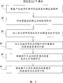
Fig. 3 is a block diagram and the main-process stream that the inventive method is shown.
Fig. 4 is a block diagram and is shown specifically preliminary treatment according to the frame 48 of Fig. 3.
Fig. 5 is a block diagram and is shown specifically total drift correction according to the frame 50 of Fig. 3.
Fig. 6 is a block diagram and is shown specifically part coupling according to the frame 52 of Fig. 3.
Fig. 7 is a schematic diagram and measured value by reality is shown to the correction of the path loss matrix of initial existence.
Fig. 8 is a schematic diagram and the process that the interpolating function that descends to all sides from reference point is shown with isocontour form.
Embodiment
Represent thin graticule mesh with 10 in Fig. 1, this thin graticule mesh is divided into the radio plot of radio net the grid of little area piece 12.The value of each area piece 12 apportion model amount of giving.These model values for example are made of path loss data.The transmitting power of path loss data explanation emission of the direction towards relevant area piece 12 from the cell site is in the decay on the radio channel of relevant area piece 12.By putting 14 model values of representing to be assigned to area piece 12.Model value obtains from channel model.This channel model at first is also to be developed according to the relation of finding by rule of thumb under considering such as the situation of Different Effects such as distance, topography, building and plant as Mathematical Modeling.This channel model is not generally still with actual consistent.Make this channel model and actual match by measurement.At this, can not in each single area piece, carry out described measurement.In Fig. 1,16 carry out the measurement of the actual value of model value or physical quantity, for example received power along the path, wherein derive model value according to described physical quantity, obtain path loss data according to received power.This path for example can be the street, and measuring vehicle is travelled along this street.Obtain depending on the measurement data of position, these measurement data are represented with point 18 in Fig. 1.
According to these measurement data 18 that do not detect all area pieces 12, directly carry out the correction of model value 14 by interpolation.This realizes in the following manner:
Thick graticule mesh 20 is added on the thin graticule mesh 10.Thick graticule mesh 20 is divided into zone 22 with radio plot.In these zones 22 each comprises the little area piece 12 of a greater number.Determine a reference point 24 in these zones 22 each.Reasonably, the mid point in this reference point 24 zone 22 that is substantial rectangular.
In order to revise the radio net model, present following taking measures:
At first carry out the overall situation correction of skew of the model value of whole radio plot.For this purpose, on whole radio plot, form the mean value of measured value on the one hand, form the mean value of model value on the other hand.Model value is corrected the difference of these mean values all.
But, this step still allow measured value and the model value that so is corrected between partial deviations.Carry out the other part coupling of model value by interpolation.For this purpose, for each zone 22 of thick graticule mesh 20 forms the mean value of measurement data, wherein in each zone, obtain this measurement data.Model value in the mid point 24 in such zone is set to depend on the value of this mean value.The model value of the other area piece 12 in this zone according to from this point along with the function that the increase with the distance of mid point reduces is revised.
Figure 2 illustrates the device that is used to carry out described method.Represent radio net with 26 in Fig. 2, this radio net is schematically shown at this.The measurement data that measuring equipment 28 receives from radio net.This measuring equipment 28 moves, and moves along the path 16 of Fig. 1 in this example.This measuring equipment 28 can be installed on the measuring vehicle.This measuring equipment 28 also can be the terminal equipment of radio net.This measuring equipment comprises the equipment of the current location that is used for definite measuring equipment.This equipment can be satellite navigation receiver (for example GPS) or orientation equipment, and this orientation equipment is determined the position of described measuring equipment by the orientation of measuring a plurality of cell sites.
Described radio net comprises a plurality of radio plots that may be overlapping.Each radio plot has the sign of himself.Described measuring equipment responds these signs.Thus, resulting measurement data can be assigned to each radio plot respectively under overlapping situation.
The measurement data that is obtained can be determined, writes down and be exported to measuring equipment 28.
The data of radio net 26 are stored in the database 32.The model value that wherein also has " initial ", uncorrected radio net model.This illustrates by the bidirectional interface between database 32 and the radio net 26 in Fig. 2.Database 32 carries out exchanges data via bidirectional interface 34 and computing equipment 36 again.
In computing equipment 36, the radio net model that at first will have the model value of radio net layout data form is stored in the memory 38.Computing unit 40 obtains measurement data from measuring equipment 28.This represents by arrow 42.This computing unit 40 carries out bidirectional data exchange with memory 38.Therefore, computing unit 40 obtains the model value and the measurement data of radio net model.Computing unit is carried out above-mentioned data operation in view of the above, is that model value is with respect to the correction of the skew of measuring amount and local correction subsequently.The model value that so is corrected is passed back in the memory, and is stored in the database 32 via interface 34.Computing unit 40 is by the on commission personnel operation of carrying out radio net planning and optimizing.
Described database obtains about the information of the variation the radio net or for example about the information of the quantity of unfounded connection from radio net 26 via interface 30.These information are considered when optimizing radio net.
In concrete enforcement according to the inventive method of Fig. 3, exist 66 cell sites with UMTS network, size is about 53km
2The radio net layout data 44 in city.Each one to three of cell site's domination has the independently sub-district of antenna respectively.
Including Terrain Elevation figure in the radio net layout data, is all radio plot calculating path loss matrix by this Terrain Elevation figure according to quite rough radio propagation model.Especially the influence of the building structure in the zone that may not note being investigated in this propagation model is not because exist any data to this.Therefore, just in this point, should reckon with these path loss prediction data and the measured value of the path loss that in this zone, write down between the tangible deviation of part.For the path loss matrix has been selected the resolution of 25m * 25m, determine the little area piece of the thin graticule mesh mentioned in the claim 1 thus.
In addition, in the radio net layout data, also include about the explanation of position, cell site, the antenna that uses in the radio plot place together with its direction and other additional attenuation factors.Antenna is represented by the suitable three-dimensional modeling of its antenna diagram.In addition, in the radio net layout data, store reference or the transmitting power of pilot signal and the cell ID that is launched equally that is launched from each radio plot with the scrambler form.By means of these explanations, can calculate the plane distribution of the predicted received power of pilot signal equally with matrix form according to path loss given in the matrix.This received power matrix have with based on the identical grid division of path loss matrix, promptly be 25m * 25m in this example.
In the actual area that is reflected by existing radio net layout data of UMTS radio net, utilized the mobile wireless electrical measuring device to carry out measurement.Described measuring equipment not only can measurement pilot signals received power, but also can detect: which radio plot to have launched corresponding pilot signal from according to corresponding scrambler.In addition, at the measured value that each write down, determined receiving position and stored this receiving position equally by gps receiver.During measuring, utilize the mobile wireless electrical measuring device to roll a series of streets away from, so that the input data of measured value 46 conducts of sufficient amount according to Fig. 3 are provided from the zone of being investigated.In order before coupling measured value to be compared with the predicted value of the received power of pilot signal, at first suitably average to both in the part, and then compare at all places, measuring position.Obtain in the case in this example, between them, when standard deviation surpasses 11dB, have the average deviation that surpasses 13.5dB.
The inventive method is implemented on computing equipment, the feasible coupling that can automatically carry out the path loss matrix by means of measured value.At first in step 48, the input data are carried out preliminary treatment.According to Fig. 4, at first in step 56, determine to have the thick graticule mesh of the grid of 250m * 250m at this, wherein the distance of two of this thick graticule mesh adjacent area pieces is approximately corresponding to the average distance in two streets that have measured value.Then, utilize this parametrization, in step 58, measured value is distributed to geographically the corresponding area piece of thick graticule mesh, and average with in step 60, pursuing the sub-district.In addition, in step 62, not only generally but also at each area piece of thick graticule mesh all measured values that is assigned to a certain sub-district are counted.At this, set up cell allocation by the measured respectively scrambler of respective cell.In step 64, decide according to the sum of the measured value of each sub-district: the coupling that whether should carry out the path loss matrix on meaning of the present invention at corresponding sub-district.If for the sub-district, there is very few measured value, then abandon coupling, because existing measured value is enough unreliable.For some radio plots, for example do not have measurement data because they during measurement is travelled be close and launch.Logical ground, these sub-districts automatically are excluded outside coupling.In addition, in step 66, determine: the measured value that whether has the part coupling that enough is used for after a while at the area piece of each radio plot and thick graticule mesh.If the quantity of the measured value in definite area piece of a certain sub-district is lower than predetermined minimum number, then the respective area piece of respective cell is excluded outside the coupling of part.
Then, in two steps 50 and 52, carry out real coupling to the path loss matrix by means of measured value according to Fig. 3:
At first, carry out total coupling of each sub-district, for described sub-district, have abundant measured value according to the flow chart among Fig. 5.For this reason, in step 68, all measured values that are assigned to the corresponding radio sub-district via scrambler are averaged by sub-district ground.In addition, in step 70,, the received power value of being predicted in the pilot signal at place, corresponding measuring position is averaged, and two mean values are compared mutually at each sub-district.In step 72, the ratio of two mean values (perhaps with to counting unit decibel-difference) draws the total drift of predicted value with respect to measured value.In step 74, the corresponding matrix value of all area pieces of thin graticule mesh is corrected this total drift.
So in second step, carry out the part coupling of path loss matrix according to the flow chart among Fig. 6.In step 76, each the area piece at thick graticule mesh is defined as reference point with corresponding mid point.Then, in step 78, at each area piece of each sub-district and thick graticule mesh, the deviation between the received power value of being predicted of definite measured value of before having averaged and pilot signal.In step 80, these deviations (be also referred to as in addition and measure deviant) are distributed to corresponding reference point subsequently by ground, sub-district.Measuring deviant as under the situation of sampled point (Stuetzstelle), in step 82, form interpolating function, the intermediate gaps in described interpolating function between the sampled point is filled according to the function that descends with distance.In Fig. 7, show exemplary interpolating function 88, wherein by putting the 86 measurement deviants that provide in the sampled point at sub-district arbitrarily.At interpolating function, can limit the radius of influence around each sampled point, this radius of influence explanation is with the coverage apart from the function that descends.This radius of influence for example can be corresponding to the raster width (being 250m here) of thick graticule mesh.Fig. 8 illustrates the contour of exemplary interpolating function 88.Can clearly be seen that the ellipse around sampled point, these oval explanations are with the ever-increasing decline of distance.After forming interpolating function, in step 84, this interpolating function is applied to all little area pieces of the initial path loss matrix 90 of respective cell.If provide two matrixes with logarithmic scale, then this computing is addition.The result is the path loss matrix 92 of the coupling shown in the right in Fig. 7, and this path loss matrix 92 comprises the influence of the measured pilot signal received power of respective cell.Compare with initial path loss matrix 90, can obviously find out the effect of described interpolating function.Therefore, can clearly pick up exemplary three sampled values 86 choosing as the corresponding raising 94 in the resulting path loss matrix.
Because the automation of computing technique can be carried out this two-stage approach fully at all path loss matrixes in several seconds.After the path loss matrix that makes all radio plots is matched with measured value in this way, carry out measurement data and the received power matrix predicted between compare once more.Determine at this: average deviation can be reduced to and be lower than 1.4dB when standard deviation is lower than 9dB.
Claims (16)
Applications Claiming Priority (3)
| Application Number | Priority Date | Filing Date | Title |
|---|---|---|---|
| DE102004002145A DE102004002145B4 (en) | 2004-01-15 | 2004-01-15 | Method and device for adapting a radio network model to the conditions of a real radio network |
| DE102004002145.7 | 2004-01-15 | ||
| PCT/EP2005/000134 WO2005069666A1 (en) | 2004-01-15 | 2005-01-10 | Method and device for adapting a radio network model to the conditions of a real radio network |
Publications (2)
| Publication Number | Publication Date |
|---|---|
| CN1934882A true CN1934882A (en) | 2007-03-21 |
| CN1934882B CN1934882B (en) | 2010-05-12 |
Family
ID=34778065
Family Applications (1)
| Application Number | Title | Priority Date | Filing Date |
|---|---|---|---|
| CN200580008442XA Expired - Fee Related CN1934882B (en) | 2004-01-15 | 2005-01-10 | Method and arrangement for matching a radio network model to conditions of an actual radio network |
Country Status (9)
| Country | Link |
|---|---|
| US (1) | US7877095B2 (en) |
| EP (1) | EP1606965B1 (en) |
| JP (1) | JP4499746B2 (en) |
| KR (1) | KR101121435B1 (en) |
| CN (1) | CN1934882B (en) |
| AT (1) | ATE441298T1 (en) |
| DE (2) | DE102004002145B4 (en) |
| ES (1) | ES2329808T3 (en) |
| WO (1) | WO2005069666A1 (en) |
Cited By (3)
| Publication number | Priority date | Publication date | Assignee | Title |
|---|---|---|---|---|
| CN102598521A (en) * | 2009-06-19 | 2012-07-18 | 科达无线私人有限公司 | Characterisation of a wireless communications link |
| CN102869020A (en) * | 2011-07-08 | 2013-01-09 | 中国移动通信集团湖南有限公司 | Method and device for optimizing wireless network |
| CN104145500A (en) * | 2011-12-14 | 2014-11-12 | 埃克提克斯有限责任公司 | Method and system for maintaining or optimizing a mobile telephone network |
Families Citing this family (25)
| Publication number | Priority date | Publication date | Assignee | Title |
|---|---|---|---|---|
| JP5108024B2 (en) * | 2006-12-18 | 2012-12-26 | テレフオンアクチーボラゲット エル エム エリクソン(パブル) | Network configuration audit |
| FI121980B (en) * | 2007-02-16 | 2011-06-30 | Voyantic Oy | Method for characterizing a radio link |
| WO2008123809A1 (en) * | 2007-04-04 | 2008-10-16 | Telefonaktiebolaget Lm Ericsson (Publ) | Method and arrangement for improved radio network planning, simulation and analyzing in telecommunications |
| US8385908B2 (en) | 2008-02-07 | 2013-02-26 | Optimi Corporation | Modifying mobile network signal propagation predictions |
| US8098590B2 (en) * | 2008-06-13 | 2012-01-17 | Qualcomm Incorporated | Apparatus and method for generating performance measurements in wireless networks |
| US8498207B2 (en) * | 2008-06-26 | 2013-07-30 | Reverb Networks | Dynamic load balancing |
| JP5139462B2 (en) | 2009-03-16 | 2013-02-06 | アクティックス・ゲゼルシャフト・ミト・べシュレンクテル・ハフツング | A method for approximating and optimizing the gain of capacity and coverage obtained by deploying multi-antennas in cellular radio networks |
| JP5299135B2 (en) * | 2009-07-09 | 2013-09-25 | 日本電気株式会社 | COMPUTER DEVICE, BASE STATION CONTROL DEVICE, WIRELESS COMMUNICATION SYSTEM, AND CALCULATION METHOD |
| US20110090820A1 (en) | 2009-10-16 | 2011-04-21 | Osama Hussein | Self-optimizing wireless network |
| US9826416B2 (en) | 2009-10-16 | 2017-11-21 | Viavi Solutions, Inc. | Self-optimizing wireless network |
| US8385900B2 (en) * | 2009-12-09 | 2013-02-26 | Reverb Networks | Self-optimizing networks for fixed wireless access |
| US8509762B2 (en) | 2011-05-20 | 2013-08-13 | ReVerb Networks, Inc. | Methods and apparatus for underperforming cell detection and recovery in a wireless network |
| WO2013036793A1 (en) | 2011-09-09 | 2013-03-14 | ReVerb Networks, Inc. | Methods and apparatus for implementing a self optimizing-organizing network manager |
| US9258719B2 (en) | 2011-11-08 | 2016-02-09 | Viavi Solutions Inc. | Methods and apparatus for partitioning wireless network cells into time-based clusters |
| US9008722B2 (en) | 2012-02-17 | 2015-04-14 | ReVerb Networks, Inc. | Methods and apparatus for coordination in multi-mode networks |
| DE102012003977A1 (en) * | 2012-02-28 | 2013-08-29 | Vodafone Holding Gmbh | Method for examining a data transport network and computer program product |
| US9271157B2 (en) * | 2013-11-25 | 2016-02-23 | Motorola Solutions, Inc. | Method of and system for optimizing an empirical propagation prediction model in a mobile communications network |
| WO2016033736A1 (en) * | 2014-09-02 | 2016-03-10 | 华为技术有限公司 | Cell selection method in wireless network, base station and user equipment |
| US9113353B1 (en) | 2015-02-27 | 2015-08-18 | ReVerb Networks, Inc. | Methods and apparatus for improving coverage and capacity in a wireless network |
| US20170219118A1 (en) * | 2016-01-28 | 2017-08-03 | Hamilton Sundstrand Corporation | Bleed valve position sensor |
| CN108307397A (en) * | 2017-01-13 | 2018-07-20 | 中国移动通信集团四川有限公司 | Network coverage evaluation method and system |
| US11095377B2 (en) * | 2017-12-08 | 2021-08-17 | Commscope Technologies Llc | Methods and systems for determining morphology data |
| CN114930894B (en) * | 2020-01-17 | 2025-03-14 | 英国电讯有限公司 | Wireless telecommunications network |
| CN113761797B (en) * | 2021-08-27 | 2023-05-23 | 北京航天晨信科技有限责任公司 | Wireless channel path loss model prediction method based on computer vision |
| CN115564180B (en) * | 2022-09-01 | 2023-10-10 | 北京京能清洁能源电力股份有限公司北京分公司 | Power network reliability assessment method based on big data analysis |
Family Cites Families (9)
| Publication number | Priority date | Publication date | Assignee | Title |
|---|---|---|---|---|
| FI100043B (en) * | 1992-01-23 | 1997-08-29 | Nokia Telecommunications Oy | Cellular radio network design method and system |
| JP3709105B2 (en) * | 1999-07-23 | 2005-10-19 | 株式会社エヌ・ティ・ティ・ドコモ | Other channel communication quality estimation system using measurement channel and its communication quality estimation method |
| US6611500B1 (en) | 1999-11-04 | 2003-08-26 | Lucent Technologies, Inc. | Methods and apparatus for derivative-based optimization of wireless network performance |
| MXPA01006905A (en) | 2000-07-10 | 2003-08-20 | Scoreboard Inc | Wireless system signal propagation collection and analysis. |
| US6971063B1 (en) * | 2000-07-28 | 2005-11-29 | Wireless Valley Communications Inc. | System, method, and apparatus for portable design, deployment, test, and optimization of a communication network |
| GB0105910D0 (en) * | 2001-03-09 | 2001-04-25 | Cellular Design Services Ltd | Measurement-based prediction method for radiation path loss |
| CN1173598C (en) * | 2001-07-14 | 2004-10-27 | 华为技术有限公司 | The Method of Adapting the Coding Mode of General Packet Radio Service to Change the Service Model |
| FR2828623B1 (en) * | 2001-08-10 | 2003-09-26 | Radiotelephone Sfr | METHOD FOR ESTABLISHING A RADIO COVERAGE CARD |
| EP1355467B8 (en) * | 2002-04-16 | 2005-12-07 | Sony Deutschland Gmbh | Orthogonal frequency division multiplexing (OFDM) system with channel transfer function prediction |
-
2004
- 2004-01-15 DE DE102004002145A patent/DE102004002145B4/en not_active Expired - Fee Related
-
2005
- 2005-01-10 WO PCT/EP2005/000134 patent/WO2005069666A1/en active Application Filing
- 2005-01-10 JP JP2006548238A patent/JP4499746B2/en not_active Expired - Fee Related
- 2005-01-10 EP EP05700777A patent/EP1606965B1/en not_active Expired - Lifetime
- 2005-01-10 DE DE502005007977T patent/DE502005007977D1/en not_active Expired - Fee Related
- 2005-01-10 KR KR1020067016027A patent/KR101121435B1/en not_active IP Right Cessation
- 2005-01-10 CN CN200580008442XA patent/CN1934882B/en not_active Expired - Fee Related
- 2005-01-10 AT AT05700777T patent/ATE441298T1/en not_active IP Right Cessation
- 2005-01-10 ES ES05700777T patent/ES2329808T3/en not_active Expired - Lifetime
-
2006
- 2006-07-14 US US11/486,951 patent/US7877095B2/en not_active Expired - Fee Related
Cited By (6)
| Publication number | Priority date | Publication date | Assignee | Title |
|---|---|---|---|---|
| CN102598521A (en) * | 2009-06-19 | 2012-07-18 | 科达无线私人有限公司 | Characterisation of a wireless communications link |
| CN102869020A (en) * | 2011-07-08 | 2013-01-09 | 中国移动通信集团湖南有限公司 | Method and device for optimizing wireless network |
| CN102869020B (en) * | 2011-07-08 | 2015-07-29 | 中国移动通信集团湖南有限公司 | A kind of method of radio network optimization and device |
| CN104145500A (en) * | 2011-12-14 | 2014-11-12 | 埃克提克斯有限责任公司 | Method and system for maintaining or optimizing a mobile telephone network |
| CN104145500B (en) * | 2011-12-14 | 2018-09-14 | 埃克提克斯有限责任公司 | Method and system for maintaining or optimizing mobile telephone network |
| US10091668B2 (en) | 2011-12-14 | 2018-10-02 | Actix Limited | Mobile phone network management systems |
Also Published As
| Publication number | Publication date |
|---|---|
| JP4499746B2 (en) | 2010-07-07 |
| JP2007525879A (en) | 2007-09-06 |
| ATE441298T1 (en) | 2009-09-15 |
| WO2005069666A1 (en) | 2005-07-28 |
| US20070010204A1 (en) | 2007-01-11 |
| CN1934882B (en) | 2010-05-12 |
| KR20070000477A (en) | 2007-01-02 |
| ES2329808T3 (en) | 2009-12-01 |
| EP1606965A1 (en) | 2005-12-21 |
| US7877095B2 (en) | 2011-01-25 |
| DE102004002145A1 (en) | 2005-10-06 |
| DE502005007977D1 (en) | 2009-10-08 |
| DE102004002145B4 (en) | 2007-11-22 |
| KR101121435B1 (en) | 2012-03-16 |
| EP1606965B1 (en) | 2009-08-26 |
Similar Documents
| Publication | Publication Date | Title |
|---|---|---|
| CN1934882A (en) | Method and device for adapting a radio network model to the conditions of a real radio network | |
| CN102404756B (en) | Antenna parameter optimizing system based on mobile phone measurement report | |
| CN1149893C (en) | Method and apparatus for managing location measurement data | |
| CN1202678C (en) | Method and system for estimating subscriber's location in cluttered area | |
| EP2620024B1 (en) | Generation and use of coverage area models | |
| CN107846688B (en) | Wireless network site planning method and device based on multiple operators | |
| JP2002204468A (en) | Path loss data normalization for growth management of cellular system | |
| EP1876732A1 (en) | Search method, search system, and search program | |
| CN108182508A (en) | A kind of method and system of electric automobile charging station planning | |
| CN1333984A (en) | Determining subscriber demands on communiations system | |
| CN106412973A (en) | Network coverage quality detection method and device | |
| CN1336772A (en) | Radio network design, regulation or operation method and device | |
| KR20060136447A (en) | Method and device for adapting a radio network model to the conditions of a real radio network | |
| CN103179582A (en) | A method and system for site selection of a room division system | |
| CN115988421A (en) | Time weight clustering-based occupational and residential area estimation method and device | |
| WO2019112708A1 (en) | Methods and systems for determining morphology data | |
| CN113395704B (en) | A 5G base station site selection method and device | |
| CN101247613A (en) | Wireless signal propagation model test approach and system used for honeycomb network | |
| WO2012075805A1 (en) | Method and device for optimizing automatic cell planning using drive test data | |
| CN107094302A (en) | A kind of network coverage evaluation method and system | |
| CN1253048C (en) | System and method for determining cumulative clutter path loss | |
| CN1360802A (en) | Location of mobile station in telecommunication system | |
| CN1887014A (en) | Method and system for electromagnetic field evaluation | |
| CN109994832B (en) | Antenna feeder adjusting method, device and system | |
| JP2005072667A (en) | Apparatus and method of estimating reception characteristic |
Legal Events
| Date | Code | Title | Description |
|---|---|---|---|
| C06 | Publication | ||
| PB01 | Publication | ||
| C10 | Entry into substantive examination | ||
| SE01 | Entry into force of request for substantive examination | ||
| C14 | Grant of patent or utility model | ||
| GR01 | Patent grant | ||
| CF01 | Termination of patent right due to non-payment of annual fee | ||
| CF01 | Termination of patent right due to non-payment of annual fee |
Granted publication date: 20100512 |