CN1322254A - Small volume (in vitro) analyte sensor with diffusible or non-leachable redox mediator - Google Patents
Small volume (in vitro) analyte sensor with diffusible or non-leachable redox mediator Download PDFInfo
- Publication number
- CN1322254A CN1322254A CN99811815A CN99811815A CN1322254A CN 1322254 A CN1322254 A CN 1322254A CN 99811815 A CN99811815 A CN 99811815A CN 99811815 A CN99811815 A CN 99811815A CN 1322254 A CN1322254 A CN 1322254A
- Authority
- CN
- China
- Prior art keywords
- electrode
- sensor
- analyte
- sample
- counter
- Prior art date
- Legal status (The legal status is an assumption and is not a legal conclusion. Google has not performed a legal analysis and makes no representation as to the accuracy of the status listed.)
- Granted
Links
Images


Classifications
-
- G—PHYSICS
- G01—MEASURING; TESTING
- G01N—INVESTIGATING OR ANALYSING MATERIALS BY DETERMINING THEIR CHEMICAL OR PHYSICAL PROPERTIES
- G01N27/00—Investigating or analysing materials by the use of electric, electrochemical, or magnetic means
- G01N27/26—Investigating or analysing materials by the use of electric, electrochemical, or magnetic means by investigating electrochemical variables; by using electrolysis or electrophoresis
- G01N27/28—Electrolytic cell components
- G01N27/30—Electrodes, e.g. test electrodes; Half-cells
- G01N27/327—Biochemical electrodes, e.g. electrical or mechanical details for in vitro measurements
- G01N27/3271—Amperometric enzyme electrodes for analytes in body fluids, e.g. glucose in blood
- G01N27/3272—Test elements therefor, i.e. disposable laminated substrates with electrodes, reagent and channels
-
- C—CHEMISTRY; METALLURGY
- C12—BIOCHEMISTRY; BEER; SPIRITS; WINE; VINEGAR; MICROBIOLOGY; ENZYMOLOGY; MUTATION OR GENETIC ENGINEERING
- C12Q—MEASURING OR TESTING PROCESSES INVOLVING ENZYMES, NUCLEIC ACIDS OR MICROORGANISMS; COMPOSITIONS OR TEST PAPERS THEREFOR; PROCESSES OF PREPARING SUCH COMPOSITIONS; CONDITION-RESPONSIVE CONTROL IN MICROBIOLOGICAL OR ENZYMOLOGICAL PROCESSES
- C12Q1/00—Measuring or testing processes involving enzymes, nucleic acids or microorganisms; Compositions therefor; Processes of preparing such compositions
- C12Q1/001—Enzyme electrodes
- C12Q1/005—Enzyme electrodes involving specific analytes or enzymes
- C12Q1/006—Enzyme electrodes involving specific analytes or enzymes for glucose
-
- C—CHEMISTRY; METALLURGY
- C12—BIOCHEMISTRY; BEER; SPIRITS; WINE; VINEGAR; MICROBIOLOGY; ENZYMOLOGY; MUTATION OR GENETIC ENGINEERING
- C12Q—MEASURING OR TESTING PROCESSES INVOLVING ENZYMES, NUCLEIC ACIDS OR MICROORGANISMS; COMPOSITIONS OR TEST PAPERS THEREFOR; PROCESSES OF PREPARING SUCH COMPOSITIONS; CONDITION-RESPONSIVE CONTROL IN MICROBIOLOGICAL OR ENZYMOLOGICAL PROCESSES
- C12Q1/00—Measuring or testing processes involving enzymes, nucleic acids or microorganisms; Compositions therefor; Processes of preparing such compositions
- C12Q1/26—Measuring or testing processes involving enzymes, nucleic acids or microorganisms; Compositions therefor; Processes of preparing such compositions involving oxidoreductase
- C12Q1/32—Measuring or testing processes involving enzymes, nucleic acids or microorganisms; Compositions therefor; Processes of preparing such compositions involving oxidoreductase involving dehydrogenase
-
- G—PHYSICS
- G01—MEASURING; TESTING
- G01N—INVESTIGATING OR ANALYSING MATERIALS BY DETERMINING THEIR CHEMICAL OR PHYSICAL PROPERTIES
- G01N27/00—Investigating or analysing materials by the use of electric, electrochemical, or magnetic means
- G01N27/26—Investigating or analysing materials by the use of electric, electrochemical, or magnetic means by investigating electrochemical variables; by using electrolysis or electrophoresis
- G01N27/28—Electrolytic cell components
- G01N27/30—Electrodes, e.g. test electrodes; Half-cells
- G01N27/327—Biochemical electrodes, e.g. electrical or mechanical details for in vitro measurements
- G01N27/3271—Amperometric enzyme electrodes for analytes in body fluids, e.g. glucose in blood
- G01N27/3274—Corrective measures, e.g. error detection, compensation for temperature or hematocrit, calibration
-
- Y—GENERAL TAGGING OF NEW TECHNOLOGICAL DEVELOPMENTS; GENERAL TAGGING OF CROSS-SECTIONAL TECHNOLOGIES SPANNING OVER SEVERAL SECTIONS OF THE IPC; TECHNICAL SUBJECTS COVERED BY FORMER USPC CROSS-REFERENCE ART COLLECTIONS [XRACs] AND DIGESTS
- Y10—TECHNICAL SUBJECTS COVERED BY FORMER USPC
- Y10T—TECHNICAL SUBJECTS COVERED BY FORMER US CLASSIFICATION
- Y10T156/00—Adhesive bonding and miscellaneous chemical manufacture
- Y10T156/10—Methods of surface bonding and/or assembly therefor
- Y10T156/1052—Methods of surface bonding and/or assembly therefor with cutting, punching, tearing or severing
-
- Y—GENERAL TAGGING OF NEW TECHNOLOGICAL DEVELOPMENTS; GENERAL TAGGING OF CROSS-SECTIONAL TECHNOLOGIES SPANNING OVER SEVERAL SECTIONS OF THE IPC; TECHNICAL SUBJECTS COVERED BY FORMER USPC CROSS-REFERENCE ART COLLECTIONS [XRACs] AND DIGESTS
- Y10—TECHNICAL SUBJECTS COVERED BY FORMER USPC
- Y10T—TECHNICAL SUBJECTS COVERED BY FORMER US CLASSIFICATION
- Y10T29/00—Metal working
- Y10T29/49—Method of mechanical manufacture
- Y10T29/49002—Electrical device making
- Y10T29/49004—Electrical device making including measuring or testing of device or component part
-
- Y—GENERAL TAGGING OF NEW TECHNOLOGICAL DEVELOPMENTS; GENERAL TAGGING OF CROSS-SECTIONAL TECHNOLOGIES SPANNING OVER SEVERAL SECTIONS OF THE IPC; TECHNICAL SUBJECTS COVERED BY FORMER USPC CROSS-REFERENCE ART COLLECTIONS [XRACs] AND DIGESTS
- Y10—TECHNICAL SUBJECTS COVERED BY FORMER USPC
- Y10T—TECHNICAL SUBJECTS COVERED BY FORMER US CLASSIFICATION
- Y10T29/00—Metal working
- Y10T29/49—Method of mechanical manufacture
- Y10T29/49002—Electrical device making
- Y10T29/49007—Indicating transducer
-
- Y—GENERAL TAGGING OF NEW TECHNOLOGICAL DEVELOPMENTS; GENERAL TAGGING OF CROSS-SECTIONAL TECHNOLOGIES SPANNING OVER SEVERAL SECTIONS OF THE IPC; TECHNICAL SUBJECTS COVERED BY FORMER USPC CROSS-REFERENCE ART COLLECTIONS [XRACs] AND DIGESTS
- Y10—TECHNICAL SUBJECTS COVERED BY FORMER USPC
- Y10T—TECHNICAL SUBJECTS COVERED BY FORMER US CLASSIFICATION
- Y10T29/00—Metal working
- Y10T29/49—Method of mechanical manufacture
- Y10T29/49002—Electrical device making
- Y10T29/49117—Conductor or circuit manufacturing
- Y10T29/49124—On flat or curved insulated base, e.g., printed circuit, etc.
- Y10T29/49126—Assembling bases
-
- Y—GENERAL TAGGING OF NEW TECHNOLOGICAL DEVELOPMENTS; GENERAL TAGGING OF CROSS-SECTIONAL TECHNOLOGIES SPANNING OVER SEVERAL SECTIONS OF THE IPC; TECHNICAL SUBJECTS COVERED BY FORMER USPC CROSS-REFERENCE ART COLLECTIONS [XRACs] AND DIGESTS
- Y10—TECHNICAL SUBJECTS COVERED BY FORMER USPC
- Y10T—TECHNICAL SUBJECTS COVERED BY FORMER US CLASSIFICATION
- Y10T29/00—Metal working
- Y10T29/49—Method of mechanical manufacture
- Y10T29/49002—Electrical device making
- Y10T29/49117—Conductor or circuit manufacturing
- Y10T29/49124—On flat or curved insulated base, e.g., printed circuit, etc.
- Y10T29/49128—Assembling formed circuit to base
-
- Y—GENERAL TAGGING OF NEW TECHNOLOGICAL DEVELOPMENTS; GENERAL TAGGING OF CROSS-SECTIONAL TECHNOLOGIES SPANNING OVER SEVERAL SECTIONS OF THE IPC; TECHNICAL SUBJECTS COVERED BY FORMER USPC CROSS-REFERENCE ART COLLECTIONS [XRACs] AND DIGESTS
- Y10—TECHNICAL SUBJECTS COVERED BY FORMER USPC
- Y10T—TECHNICAL SUBJECTS COVERED BY FORMER US CLASSIFICATION
- Y10T29/00—Metal working
- Y10T29/49—Method of mechanical manufacture
- Y10T29/49002—Electrical device making
- Y10T29/49117—Conductor or circuit manufacturing
- Y10T29/49124—On flat or curved insulated base, e.g., printed circuit, etc.
- Y10T29/4913—Assembling to base an electrical component, e.g., capacitor, etc.
-
- Y—GENERAL TAGGING OF NEW TECHNOLOGICAL DEVELOPMENTS; GENERAL TAGGING OF CROSS-SECTIONAL TECHNOLOGIES SPANNING OVER SEVERAL SECTIONS OF THE IPC; TECHNICAL SUBJECTS COVERED BY FORMER USPC CROSS-REFERENCE ART COLLECTIONS [XRACs] AND DIGESTS
- Y10—TECHNICAL SUBJECTS COVERED BY FORMER USPC
- Y10T—TECHNICAL SUBJECTS COVERED BY FORMER US CLASSIFICATION
- Y10T29/00—Metal working
- Y10T29/49—Method of mechanical manufacture
- Y10T29/49002—Electrical device making
- Y10T29/49117—Conductor or circuit manufacturing
- Y10T29/49124—On flat or curved insulated base, e.g., printed circuit, etc.
- Y10T29/49147—Assembling terminal to base
-
- Y—GENERAL TAGGING OF NEW TECHNOLOGICAL DEVELOPMENTS; GENERAL TAGGING OF CROSS-SECTIONAL TECHNOLOGIES SPANNING OVER SEVERAL SECTIONS OF THE IPC; TECHNICAL SUBJECTS COVERED BY FORMER USPC CROSS-REFERENCE ART COLLECTIONS [XRACs] AND DIGESTS
- Y10—TECHNICAL SUBJECTS COVERED BY FORMER USPC
- Y10T—TECHNICAL SUBJECTS COVERED BY FORMER US CLASSIFICATION
- Y10T29/00—Metal working
- Y10T29/49—Method of mechanical manufacture
- Y10T29/49002—Electrical device making
- Y10T29/49117—Conductor or circuit manufacturing
- Y10T29/49124—On flat or curved insulated base, e.g., printed circuit, etc.
- Y10T29/49155—Manufacturing circuit on or in base
-
- Y—GENERAL TAGGING OF NEW TECHNOLOGICAL DEVELOPMENTS; GENERAL TAGGING OF CROSS-SECTIONAL TECHNOLOGIES SPANNING OVER SEVERAL SECTIONS OF THE IPC; TECHNICAL SUBJECTS COVERED BY FORMER USPC CROSS-REFERENCE ART COLLECTIONS [XRACs] AND DIGESTS
- Y10—TECHNICAL SUBJECTS COVERED BY FORMER USPC
- Y10T—TECHNICAL SUBJECTS COVERED BY FORMER US CLASSIFICATION
- Y10T29/00—Metal working
- Y10T29/49—Method of mechanical manufacture
- Y10T29/49002—Electrical device making
- Y10T29/49117—Conductor or circuit manufacturing
- Y10T29/49204—Contact or terminal manufacturing
- Y10T29/49208—Contact or terminal manufacturing by assembling plural parts
- Y10T29/4921—Contact or terminal manufacturing by assembling plural parts with bonding
-
- Y—GENERAL TAGGING OF NEW TECHNOLOGICAL DEVELOPMENTS; GENERAL TAGGING OF CROSS-SECTIONAL TECHNOLOGIES SPANNING OVER SEVERAL SECTIONS OF THE IPC; TECHNICAL SUBJECTS COVERED BY FORMER USPC CROSS-REFERENCE ART COLLECTIONS [XRACs] AND DIGESTS
- Y10—TECHNICAL SUBJECTS COVERED BY FORMER USPC
- Y10T—TECHNICAL SUBJECTS COVERED BY FORMER US CLASSIFICATION
- Y10T29/00—Metal working
- Y10T29/49—Method of mechanical manufacture
- Y10T29/49789—Obtaining plural product pieces from unitary workpiece
- Y10T29/49794—Dividing on common outline
Landscapes
- Chemical & Material Sciences (AREA)
- Life Sciences & Earth Sciences (AREA)
- Health & Medical Sciences (AREA)
- Organic Chemistry (AREA)
- Zoology (AREA)
- Wood Science & Technology (AREA)
- Proteomics, Peptides & Aminoacids (AREA)
- Engineering & Computer Science (AREA)
- Analytical Chemistry (AREA)
- Immunology (AREA)
- Physics & Mathematics (AREA)
- Molecular Biology (AREA)
- General Health & Medical Sciences (AREA)
- Biochemistry (AREA)
- Biophysics (AREA)
- Bioinformatics & Cheminformatics (AREA)
- General Engineering & Computer Science (AREA)
- Biotechnology (AREA)
- Genetics & Genomics (AREA)
- Microbiology (AREA)
- Hematology (AREA)
- Pathology (AREA)
- Chemical Kinetics & Catalysis (AREA)
- Electrochemistry (AREA)
- General Physics & Mathematics (AREA)
- Emergency Medicine (AREA)
- Investigating Or Analysing Biological Materials (AREA)
- Apparatus Associated With Microorganisms And Enzymes (AREA)
- Measurement Of The Respiration, Hearing Ability, Form, And Blood Characteristics Of Living Organisms (AREA)
- Measuring Or Testing Involving Enzymes Or Micro-Organisms (AREA)
- Investigating Or Analysing Materials By The Use Of Chemical Reactions (AREA)
- Investigating Or Analyzing Materials By The Use Of Fluid Adsorption Or Reactions (AREA)
Abstract
A sensor utilizing a non-leachable or diffusible redox mediator is described. The sensor includes a sample chamber to hold a sample in electrolytic contact with a working electrode, and in at least some instances, the sensor also contains a non-leachable or a diffusible second electron transfer agent. The sensor and/or the methods used produce a sensor signal in response to the analyte that can be distinguished from a background signal caused by the mediator. The invention can be used to determine the concentration of a biomolecule, such as glucose or lactate, in a biological fluid, such as blood or serum, using techniques such as coulometry, amperometry, and potentiometry. An enzyme capable of catalyzing the electrooxidation or electroreduction of the biomolecule is typically provided as a second electron transfer agent.
Description
Technical Field
The present invention relates to an analytical sensor for detecting a biological analyte in a small volume of sample.
Background
Analytical sensors are useful in chemistry and medicine for determining the presence and concentration of biological analytes. These sensors are needed, for example, to monitor glucose in diabetic patients and to monitor lactate during intensive care.
The prior art measures biological analytes in relatively large sample volumes, for example, typically requiring 3 microliters or more of blood or other biological fluid. These liquid samples are obtained from the patient, for example, using a needle and syringe, or by puncturing a portion of the skin, such as a fingertip, and "squeezing" the area to obtain a useful sample volume. These methods are inconvenient for the patient and often painful, especially when samples are frequently needed. Less painful methods of obtaining samples are known, such as puncturing the arm or thigh, which have a lower nerve ending density. However, lancing the body in the preferred areas typically yields only sub-microliter blood samples because these areas are not enriched in near-surface capillaries.
It would therefore be highly desirable and highly useful to develop a blood analysis sensor that is relatively painless, easy to use, and capable of performing accurate and sensitive analyses of analyte concentrations in small sample volumes. Sensors capable of electrochemically determining an analyte in a sample are known in the art. Some sensors known in the art use at least two electrodes and may contain a redox mediator to facilitate the electrochemical reaction. However, the use of electrochemical sensors to measure analytes in small volumes introduces errors into the measurement. One type of inaccuracy results from the use of diffusible redox mediators. Because the electrodes are so close together in a small volume sensor, the diffusible redox mediator can shuttle between the working and counter electrodes and add to the analyte measurement signal. Another source of inaccuracy in small volume sensors is the difficulty in determining the volume of a small sample or determining whether the sample chamber is full. It is therefore desirable to develop a small volume electrochemical sensor that reduces errors caused by sensor and sample size.
Summary of The Invention
The sensor of the present invention provides a method for detecting and quantifying an analyte in a sub-microliter sample. In general, the invention includes methods and sensors for analyzing analytes in small volumes of samples by, for example, coulometry, amperometry and/or potentiometry. The sensor of the present invention uses a redox mediator that is either non-leachable or diffusible. The sensor also includes a sample chamber for receiving a sample in electrolytic contact with the working electrode. In many cases, the sensor also contains a second electron transfer agent that is non-leachable or diffusible.
In a preferred embodiment, the working electrode faces a counter electrode, forming an assay region between the two electrodes in the sample chamber, which may be sized to contain no more than about 1 μ L of sample, preferably no more than about 0.5 μ L, more preferably no more than about 0.25 μ L, and most preferably no more than about 0.1 μ L of sample. An adsorbent is optionally included in the sample chamber and the measurement zone to reduce the volume of sample required to fill the sample chamber and the measurement zone.
In one embodiment of the present invention, a biosensor is provided that combines coulometric electrochemical sensing with a non-leachable or diffusible redox mediator to accurately and efficiently determine biological analytes in sub-microliter volumes of a sample. Preferred sensors include electrodes, a non-leachable or diffusible redox mediator on the electrodes, a sample chamber for holding a sample in electrical contact with the electrodes, and preferably, an adsorbent disposed within the sample chamber for reducing the volume of the sample chamber. The sample chamber containing any adsorbent is sized for analysis of a sample volume generally not exceeding about 1 μ L, preferably not exceeding about 0.5 μ L, more preferably not exceeding about 0.25 μ L, and most preferably not exceeding about 0.1 μ L. In some cases, the sensor also contains a second electron transfer agent that is non-leachable or diffusible.
One embodiment of the present invention includes a method of determining the concentration of an analyte in a sample by first contacting the sample with an electrochemical sensor and then determining the concentration of the analyte. The electrochemical sensor includes a facing electrode pair consisting of a working electrode and a counter electrode and a sample chamber between the two electrodes, including a measurement zone. The size of the assay region may contain no more than about 1 μ L of sample.
The invention also includes an electrochemical sensor having two or more facing electrode pairs. Each electrode pair includes a working electrode, a counter electrode, and a measurement zone disposed between the electrodes, the measurement zone being sized to accommodate no more than about 1 μ L of sample. In addition, the sensor also includes a non-leachable redox mediator located on the working electrode of at least one electrode pair, or a diffusible redox mediator located on the sample chamber surface or in the sample.
One aspect of the invention is a method of determining the concentration of an analyte in a sample comprising contacting the sample with an electrochemical sensor and coulometrically determining the concentration of the analyte. The electrochemical sensor includes an electrode pair consisting of a working electrode and a counter electrode. The sensor also includes a sample chamber for receiving a sample in electrolytic contact with the working electrode. The adsorbent is contained within the sample chamber to reduce the volume of sample required to fill the sample chamber so that the size of the sample chamber can contain no more than about 1 μ L of sample. The sample chamber also contains a non-leachable or diffusible redox mediator and optionally a non-leachable or diffusible second electron transfer agent.
The sensor may also comprise a fill indicator, such as an indicator electrode or a second electrode pair, which can determine when the measurement zone or sample chamber is full. The indicator electrode or second electrode pair may also be used to improve the accuracy of the analyte concentration determination. The sensor may also include a heating element for heating the measurement zone or sample chamber to increase the rate of oxidation or reduction of the analyte.
The sensor can be a side-fill or top-fill configuration. Additionally, in certain embodiments, the sensor may be part of an integrated sample acquisition and analyte determination device. An integrated sample acquisition and analyte determination device may include a sensor and a skin piercing member that allows the device to be used to pierce a user's skin, allowing a fluid sample, such as blood, to exit and then be collected with the sensor. In at least certain embodiments, the fluid sample can be collected without moving the integrated sample acquisition and analyte determination device.
A method of making a sensor as described above includes forming at least one working electrode on a first substrate and forming at least one counter or counter/reference electrode on a second substrate. A spacer layer is placed on the first or second substrate. The spacer layer defines a channel into which the sample can enter and be contained when the sensor is full. A redox mediator and/or a second electron transfer agent is disposed on the first or second substrate in an area that will be exposed to the interior of the trench when the sensor is full. The first and second substrates are then brought together and separated by a spacer layer with a trench to allow access to at least one working electrode and at least one counter or counter/reference electrode. In certain embodiments, the first and second substrates are part of a single sheet or continuous web of material.
Theseand various other features which characterize the invention are set forth with particularity in the appended claims. For a better understanding of the invention, its advantages, and the objects obtained by its use, reference should be made to the drawings and to the accompanying descriptive matter, in which there are illustrated and described preferred embodiments of the invention.
Brief Description of Drawings
Referring now to the drawings in which reference numerals and letters indicate corresponding structure throughout the several views:
FIG. 1 is a schematic diagram of a first embodiment of an electrochemical sensor according to the principles of the present invention having a working electrode and a counter electrode facing each other;
FIG. 2 is a schematic diagram of a second embodiment of an electrochemical sensor according to the principles of the present invention having a working electrode and a counter electrode in a co-planar configuration;
FIG. 3 is a schematic view of a third embodiment of an electrochemical sensor according to the principles of the present invention having a working electrode and a counter electrode facing each other and having an enlarged sample chamber;
FIG. 4 is a cross-sectional side view, not to scale, of a portion of the sensor of FIG. 1 or 3 showing the relative positions of the redox mediator, the sample chamber, and the electrodes;
FIG. 5 is a top view of a fourth embodiment of an electrochemical sensor according to the principles of the present invention, the sensor including a plurality of working electrodes;
FIG. 6 is a perspective view of one embodiment of an analyte determining device having a sample acquiring deviceand the sensor of FIG. 4 according to the principles of the present invention;
FIG. 7 is a graph of the charge required to electro-oxidize a known amount of glucose in an electrolyte buffer solution (filled circles) or in a serum solution (open circles) using the sensor of FIG. 1 using glucose oxidase as the second electron transfer agent;
FIG. 8 is a plot of the average glucose concentration of the data of FIG. 7 (buffer solution only) with a calibration curve calculated to fit the average; calculating a linear correction curve for concentrations of 10-20mM and a second order polynomial correction curve for concentrations of 0-10 mM;
FIG. 9 is a Clark-type clinical grid analyzing the clinical relevance of the glucose values of FIG. 7;
FIG. 10 is a graph of the charge required to electro-oxidize a known amount of glucose in an electrolyte buffer using the sensor of FIG. 1 using glucose dehydrogenase as a second electron transfer agent;
11A, 11B and 11C are top views of three configurations of overlapping working and counter electrodes according to the present invention;
FIGS. 12A and 12B are cross-sectional views of one embodiment of an electrode pair formed with base (base) material grooves in accordance with the present invention;
FIGS. 13A and 13B are cross-sectional views of another embodiment of an electrode pair of the present invention formed in a recess of a base material;
FIGS. 14A and 14B are cross-sectional views of another embodiment of an electrode pair of the present invention formed with base material grooves and an adsorbent;
FIG. 15 is a graph of the charge released over time for a sensor containing a diffusible redox mediator for several glucose concentrations;
FIG. 16 is a graph of the charge released by a sensor containing a diffusible redox mediator for several glucose concentrations;
FIG. 17 is a graph of the charge released over time for sensors containing different amounts of diffusible redox mediators;
FIG. 18A shows a top view of a first membrane with a working electrode used in a fifth embodiment of a sensor according to the present invention;
FIG. 18B shows a top view of a spacer layer to be placed on the first film of FIG. 18A;
FIG. 18C shows a bottom view (flipped over relative to FIGS. 18A and 18B) of a second membrane with a counter electrode to be placed over the spacer layer of FIG. 18B and the first membrane of FIG. 18A;
FIG. 19A shows a top view of a first membrane with a working electrode used in a sixth embodiment of a sensor according to the present invention;
FIG. 19B shows a top view of a spacer layer to be placed on the first film of FIG. 19A;
FIG. 19C shows a bottom view (flipped over relative to FIGS. 19A and 19B) of a second film with a counter electrode to be placed over the spacer layer of FIG. 19B and the first film of FIG. 19A;
FIG. 20A shows a top view of a first membrane with a working electrode used in a seventh embodiment of a sensor according to the present invention;
FIG. 20B shows a top view of a spacer layer to be placed on the first film of FIG. 20A;
FIG. 20C shows a bottom view (flipped over relative to FIGS. 20A and 20B) of a second membrane with a counter electrode to be placed over the spacer layer of FIG. 20B and the first membrane of FIG. 20A;
FIG. 21A shows a top view of a first membrane witha working electrode used in an eighth embodiment of a sensor according to the present invention;
FIG. 21B shows a top view of a spacer layer to be placed on the first film of FIG. 21A;
FIG. 21C shows a bottom view (flipped over relative to FIGS. 21A and 21B) of a second membrane with a counter electrode to be placed over the spacer layer of FIG. 21B and the first membrane of FIG. 21A;
FIG. 22A shows a top view of a first membrane with a working electrode used in a ninth embodiment of a sensor according to the invention;
FIG. 22B shows a top view of a spacer layer to be placed on the first film of FIG. 22A;
FIG. 22C shows a bottom view (flipped over relative to FIGS. 22A and 22B) of a second film with a counter electrode to be placed over the spacer layer of FIG. 22B and the first film of FIG. 22A;
FIG. 23A shows a top view of a first membrane with a working electrode used in a tenth embodiment of a sensor according to the invention;
FIG. 23B shows a top view of a spacer layer to be placed on the first film of FIG. 23A;
FIG. 23C shows a bottom view (flipped over relative to FIGS. 23A and 23B) of a second film with a counter electrode to be placed over the spacer layer of FIG. 23B and the first film of FIG. 23A;
FIG. 24A shows a top view of a first membrane with a working electrode used in an eleventh embodiment of a sensor according to the present invention;
FIG. 24B shows a top view of a spacer layer to be placed on the first film of FIG. 24A;
FIG. 24C shows a bottom view (flipped over relative to FIGS. 24A and 24B) of a second membrane with a counter electrode to be placed over the spacer layer of FIG. 24B and the first membrane of FIG. 24A;
FIG. 25 shows a top view of a twelfth embodiment of an electrochemical sensor according to the invention;
FIG. 26 shows a perspective view of one embodiment of an integrated analyte acquisition and sensor apparatus;
FIG. 27 shows a cross-sectional view of a thirteenth embodiment of a sensor according to the invention;
FIG. 28 is a graph showing the determination of analyte concentration in a blood sample taken from the upper arm of a patient using a sensor of the present invention compared to a standard blood test assay;
FIG. 29 is a graph showing the comparison of the analyte concentration in a blood sample taken from a patient's finger using the sensor of the present invention with a standard blood test assay;
FIG. 30 is a graph showing the determination of analyte concentration in a venous sample using a sensor of the present invention compared to a standard blood test assay;
FIG. 31A shows a top view of one embodiment of a piece of sensor assembly according to the present invention;
FIG. 31B shows a top view of another embodiment of a piece of sensor assembly according to the present invention;
FIG. 32 shows a cross-sectional view from inside a meter looking into a sensor of the present invention placed in the meter;
detailed description of the preferred embodiments
As used herein, the following definitions describe defined terms:
an "air-oxidizable medium" is a redox medium that can be oxidized by air, preferably such that at least 90% of the medium is in the oxidized state after storage in air as a solid or as a liquid for a certain period of time, e.g., a month or less, preferably a week or less, more preferably a day or less.
"amperometry" includes steady state amperometry, chronoamperometry and Koterey-type assays.
A "biological fluid" is any bodily fluid in which an analyte can be detected, such as blood, interstitial fluid, skin fluid, sweat, and tears.
The term "blood" in the present specification includes whole blood and cell-free components thereof, such as plasma and serum.
"coulometry" is the determination of the charge transferred or expected to be transferred, either directly on the electrode or by one or more electron transfer agents, during complete or nearly complete electrolysis of the analyte. Methods for determining charge include, for example, the determination of charge transferred during partial or almost complete electrolysis of the analyte, or more commonly, various determinations of decay current and elapsed time during electrolysis. The decaying current is caused by the reduction in the concentration of the electrolytic species caused by electrolysis.
"counter electrode" refers to one or more electrodes paired with a working electrode, through which an electrochemical current of the same magnitude and opposite sign as the current through the working electrode passes. Unless the specification indicates that the "counter electrode" does not include a reference electrode or a counter/reference electrode, the term "counter electrode" includes a counter electrode (i.e., counter/reference electrode) that also functions as a reference electrode.
An "effective diffusion coefficient" is a diffusion coefficient that characterizes the transport of a substance, such as an analyte, an enzyme, or a redox mediator, in the volume between the electrodes of an electrochemical cell. In at least some cases, the cell volume may be occupied by more than one medium (e.g., sample fluid and polymer membrane). Diffusion of species through each medium may occur at different rates. The effective diffusion coefficient corresponds to the rate of diffusion through such a volume of multimedia and is generally different from the diffusion coefficient of a substance in a cell filled with sample liquid only.
An "electrochemical sensor" is a device used to detect the presence of an analyte and/or determine the concentration of an analyte by electrochemical oxidation and reduction reactions. These reactions are converted into an electrical signal that can be correlated to the amount or concentration of the analyte.
"Electrolysis" is the electrooxidation or electroreduction of a compound either directly at an electrode or through one or more electron transfer agents (e.g., redox mediators and/or enzymes).
The term "face-to-face electrode" refers to a configuration of a working electrode and a counter electrode in which the working surface of the working electrode is substantially opposite the surface of the counter electrode. In at least some cases, the distance between the working electrode and the counter electrode is shorter than the width of the working surface of the working electrode.
A compound is "immobilized" on a surface when it is entrapped on or chemically bound to the surface.
"indicator electrodes" include one or more electrodes that partially or completely fill the detection sample chamber and/or the assay region.
A "layer" includes one or more layers.
A "measurement zone" is defined herein as a region of the sample chamber that is sized to contain only the portion of the sample to be assayed during the analyte determination procedure.
A "non-diffusible", "non-leachable" or "non-releasable" compound is a compound that does not substantially diffuse out of the working surface of the working electrode during analyte determination.
The "potential of the counter/reference electrode" is the half-cell potential of the reference electrode or the counter/reference electrode of the cell when the solution in the cell is a 0.1M NaCl solution at pH7.
"potentiometry" and "chronopotentiometry" refer to potentiometry performed at one or more time points.
A "redox mediator" is an electron transfer agent that transports electrons between the analyte and the working electrode, either directly or through a second electron transfer agent.
Unless it is stated in the specification that "reference electrode" does not include a counter/reference electrode, the "reference electrode" includes a reference electrode that also functions as a counter electrode (i.e., a counter/reference electrode).
A "second electron transfer agent" is a molecule that transports electrons between a redox mediator and an analyte.
An "adsorbent" is a material that wicks, retains, and/or is wetted by a liquid sample, and generally does not prevent diffusion of an analyte to an electrode.
"sample chamber surface" includes the surface of the working electrode, counter/reference electrode, indicator electrode, spacer, or any other surface that encloses a sample chamber.
A "working electrode" is an electrode at which an analyte is electro-oxidized or electro-reduced, with or without the action of a redox mediator.
The "working surface" is the portion of the working electrode that covers the non-leachable redox mediator and is exposed to the sample, or, if the redox mediator is diffusible, the "working surface" is the portion of the working electrode that is exposed to the sample.
The small volume in vitro analytical sensor of the present invention is used to determine the concentration of an analyte in a sample portion having a volume of no more than about 1 μ L, preferably no more than about 0.5 μ L, more preferably no more than 0.25 μ L, and most preferably no more than 0.1 μ L. The target analyte is typically present in a solution or biological fluid such as blood or serum. Referring to the drawings and in particular to FIGS. 1-4, a small volume in vitro electrochemical sensor 20 of the present invention generally includes a working electrode 22, a counter (or counter/reference) electrode 24, and a sample chamber 26 (see FIG. 4). The configuration of the sample chamber 26 is such that the sample is in electrolytic contact with both the working electrode 22 and the counter electrode 24 when the sample is in the sample chamber. This allows current to flow between the electrodes, thereby effecting electrolysis (electro-oxidation or electro-reduction) of the analyte. Working electrode
Working electrode 22 may be made of a molded carbon fiber composite material or may be constructed of an inert insulating base material such as polyester upon which is placed a suitable conductive layer. In operation, the conductive layer typically has a relatively low resistance over the potential range of the sensor and is typically electrochemically inert. Suitable conductive layers include gold, carbon, platinum, ruthenium dioxide, palladium, and conductive epoxies, such as eccomatct 5079-3 carbon-filled conductive epoxy coatings (available from w.r.grace, Woburn, Massachusetts), as well as other non-corrosive materials known to those skilled in the art. The electrodes (e.g., conductive layers) are placed on the surface of the inert material by methods such as vapor deposition or printing.
A connector 23 may be located at the end of working electrode 22 to allow easy connection of the electrode to external electronics (not shown) such as a voltage source or current measuring device. Other known methods or structures (e.g., contact pads) may be used to connect working electrode 22 to external electronics.
To prevent electrochemical reactions from occurring on the portion of the working electrode not covered by mediator, when a non-leachable mediator is used, the dielectric 40 can be placed above, below, or around the redox mediator-containing region on the electrode, as shown in FIG. 4. Suitable dielectric materials include waxes and insulating organic polymers such as polyethylene. The dielectric 40 may also cover a portion of the redox mediator on the electrode. The portion of the redox mediator that is covered will not contact the sample and therefore is not part of the working surface of the electrode. Sensing chemistry
In addition to the working electrode 22, the sample chamber 26 should also have a sensing chemistry for the analyte to be analyzed. The sensing chemistry preferably includes one redox mediator and a second electron transfer mediator, although in some cases one or the other may be used alone. The redox mediator and the second electron transfer agent may be independently diffusible or non-leachable (i.e., non-diffusible) such that one or both may be diffusible or non-leachable. The placement of the sensing chemistry may depend on whether they are diffusible or non-leachable. For example, non-leachable and/or diffusible components typically form a sensing layer on the working electrode. In addition, one or more diffusible components may be placed on either surface of the sample chamber prior to addition of the sample. As another example, one or more diffusible components may be placed in the sample prior to adding the sample to the sensor.
If the redox mediator is non-leachable, the non-leachable redox mediator is typically disposed on the working electrode 22 as the sensing layer 32. In an embodiment containing a redox mediator and a second electron transfer agent, if both the redox mediator and the second electron transfer agent are non-leachable, both non-leachable components are disposed on the working electrode 22 as the sensing layer 32.
For example, if the second electron transfer agent is diffusible and the redox mediator is non-leachable, at least the redox mediator is disposed on the working electrode 22 as the sensing layer 32. The diffusible second electron transfer agent need not be disposed on the sensing layer of the working electrode, but may be disposed on any surface of the sample chamber, including within the redox mediator sensing layer, or may be disposed in the sample. If the redox mediator is diffusible, the redox mediator may be placed on either surface of the sample chamber, or may be placed in the sample.
If both the redox mediator and the second electron transfer agent are diffusible, the diffusible components may be placed on either surface of the sample chamber and/or in the sample independently or together (i.e., each diffusible component need not be placed on the same surface of the sample chamber or in the sample).
The redox mediator, whether diffusible or non-leachable, regulates the current between working electrode 22 and the analyte and enables electrochemical analysis of molecules that may not be amenable to direct electrochemical reaction at the electrode. The mediator acts as an electron transfer agent between the electrode and the analyte.
In one embodiment, both the redox mediator and the second electron transfer agent are diffusible and are disposed on the same surface of the sample chamber, such as the working electrode. In this same device, both can be placed on, for example, a counter electrode, a counter/reference electrode, a reference electrode, or an indicator electrode. In other cases, both the redox mediator and the second electron transfer agent are diffusible and are separately placed on the surface of the sample chamber and/or in the sample. For example, the redox mediator may be disposed on the working electrode and the second electron transfer agent disposed on any surface other than the working electrode, or disposed in the sample. Similarly, the reverse is also a suitable embodiment, where the second electron transfer agent is disposed on the working electrode and the redox mediator is disposed on any surface other than the working electrode, or in the sample. As another example, the redox mediator may be disposed on the counter electrode and the second electron transfer agent is disposed on any surface other than the counter electrode, or in the sample. The reverse is also appropriate.
The diffusible redox mediator and/or the second electron transfer agent may diffuse into the sample rapidly or may diffuse over a period of time. Similarly, the diffusible redox mediator and/or second electron transfer agent may first dissolve from the surface on which it is located as a solid, and then the diffusible redox mediator and/or second electron transfer agent may diffuse into the sample rapidly or over a period of time. If a period of time is required for the redox mediator and/or the second electron transfer agent to diffuse, the user may be required to wait for a period of time before determining the analyte concentration to allow the redox mediator and/or the second electron transfer agent to diffuse.
Background signal
In at least some instances, the diffusible redox mediator may shuttle between the working electrode and the counter electrode even in the absence of the analyte. This typically produces a background signal. For coulometric assays, this background signal is referred to herein as "QBack". This background signal corresponds to the charge transferred in the electrochemical assay in the absence of analyte. The background signal generally includesTransient components and steady state components. For example, at least a portion of the transient component is generated as a result of the establishment of a concentration gradient of the mediator in a particular oxidation state. For example, at least a portion of the steady state constituents may be produced by a redox mediator shuttled between the working electrode and the counter or counter/reference electrode. Shuttling refers to the redox mediator being electro-oxidized (or electro-reduced) at the working electrode and then electro-reduced (or electro-oxidized) at the counter electrode or counter/reference electrode, such that the redox mediator can be re-oxidized (or electro-reduced) at the working electrode, such that the redox mediator cycles between electro-oxidation and electro-reduction.
The amount of redox mediator shuttling, and the steady state component of the background signal, varies with the following conditions, for example: effective diffusion coefficient of the redox mediator, sample viscosity, sample temperature, electrochemical cell size, distance between the working electrode and the counter electrode or counter/reference electrode, and angle between the working electrode and the counter electrode or counter/reference electrode.
In some cases, the steady state component of the background signal may comprise noise related to the following conditions: (a) for example, variability of sample temperature, sample viscosity, or any other parameter on which the background signal depends during the assay, (b) defects in the electrochemical cell, for example, uneven spacing of the working electrode from the counter electrode or counter/reference electrode, variations in electrode geometry, or protrusions of the working electrode, counter electrode, and/or counter/reference electrode.
While the steady state component of the background signal may be repeatable, any noise is inherently non-repeatable. Therefore, noise adversely affects accuracy. In some cases, the background signal and noise are correlated. Thus, reducing the background signal reduces noise and its induced errors. For example, reducing shuttling of the mediator between the working electrode and the counter or counter/reference electrode may reduce noise associated with changes in sample temperature and viscosity that may affect diffusion of the redox mediator.
Thus, a moderate to near-zero level of background signal is desirable in order to improve the accuracy of the assay or reduce assay error in cases where noise is reduced as well as the background signal. In at least some instances, the sensor is configured such that the background signal is at most 5 times the magnitude of the signal generated by electrolysis of the quantity of analyte. Preferably, the background signal is at most 200%, 100%, 50%, 25%, 10% or 5% of the signal generated by electrolysis of the analyte. In amperometry, this comparison may be made by determining the ratio of the current generated by shuttling of the redox mediator to the current generated by electrolysis of the analyte. In potentiometric assays, this comparison can be made by determining the potential value of the shuttling of the redox mediator and the potential value generated by electrolysis of the analyte. In the coulometry method, this comparison can be made by determining the charge transferred at the working electrode by shuttling of the redox mediator and the charge transferred at the working electrode by electrolysis of the analyte.
The magnitude of the background signal is comparable to a predetermined amount of analyte. For example, the predetermined amount of analyte in thesample can be an expected or average molar amount of analyte. The expected or average molar amount of analyte can be determined, for example, as an average of users or individuals; the mean of the population; maximum, minimum or average value of normal physiological range; a maximum or minimum physiological value for the population; a maximum or minimum physiological value of the user or individual; average, maximum or minimum deviation outside of the normal physiological range value for a user, individual or population; deviation above or below population mean; or an average, maximum or minimum deviation above or below the average normal physiological value for the user or individual. The population may be determined, for example, by health, gender, or age, such as a normal adult, child, or neonatal population. If the population is determined to be in a healthy state, the population may include a population lacking the particular condition or having the particular condition, such as diabetes. Reference intervals suitable for the mean or expected value, as described in the text "Tietz clinical chemistry, appendix (2175-page 2217) (second edition, compiled by Carl A. Burtis and Edward R. Ashwood, W.D. Saunders Co., Philadelphia 1994) (incorporated herein by reference), can be used as indicators, but the mean or expected value of an individual can also be determined by a physician by physical examination or blood chemistry tests. For example, according to the text of Tietz clinical chemistry, an adult human may have glucose at a concentration of 65-95mg/dL in whole blood and L-lactate at a concentration of 8.1-15.3mg/dL in venous whole blood after fasting. For example, the average normal physiological concentration for an adult may correspond to 80mg/dL of glucose or 12.7mg/dL of lactic acid. Other examples include patients with juvenile onset diabetes, but with better glycemic control, with glucose concentrations of about 50mg/dL to 400mg/dL, and thus an average molar amount of 225 mg/dL. In another instance, a non-diabetic adult may have a glucose concentration of about 80mg/dL (post fasting) to 140mg/dL (post feeding), thereby having an average molar mass of 110 mg/dL.
Other analytes that can be determined include, for example, acetylcholine, amylase, bilirubin, cholesterol, chorionic gonadotropin, creatine kinase (e.g., CK-MB), creatine, DNA, fructosamine, glucose, glutamine, growth hormones, ketones, lactic acid, peroxides, prostate-specific antigens, prothrombin, RNA, thyroid stimulating hormone, and troponin. The concentration of drugs such as antibiotics (e.g., gentamicin, vancomycin, and the like), digitoxin, digoxin, drugs of abuse, theophylline, and warfarin may also be determined. Assays suitable for determining DNA and/or RNA concentrations are disclosed in U.S. patent application Ser. Nos. 09/138,888 and 09/145,776 and in U.S. provisional application Ser. Nos. 60/090,517, 60/093,100 and 60/114,919, which are incorporated herein by reference.
To construct a sensor having a particular ratio of background signal to analyte electrolysis signal, several parameters relating to the redox mediator shuttling background signal and/or analyzing the current and/or charge induced by the electrolytically-generated signal may be considered and selected to achieve the desired ratio. Generally, the signal determined for coulometry is the charge; the signal measured by amperometry is the current at the time of measurement. Because the current and charge are dependent on several parameters, a desired ratio of background signal generated by shuttling of the redox mediator to signal generated by electrolysis of the analyte can be achieved with a variety of sensor configurations and methods of operating the sensor.
Controlling background signal
A method of controlling background signal includes the use of a redox mediator that can a) oxidize the analyte at a half-wave potential of no more than about +100mV relative to the potential of the reference or counter/reference electrode, as determined by cyclic voltammetry in 0.1M NaCl at pH7, or b) reduce the analyte at a half-wave potential of no less than about-100 mV relative to the potential of the reference or counter/reference electrode, as determined by cyclic voltammetry in 0.1M NaCl at pH7. A suitable reference or counter/reference electrode (e.g., silver/silver chloride electrode) may be selected. Preferably, the redox mediator can a) oxidize the analyte at a half-wave potential of no more than about +50mV, +25mV, 0mV, -25mV, -50mV, -100mV, or-150 mV versus the reference or counter/reference electrode potential, as determined by cyclic voltammetry in 0.1M NaCl at pH7, or b) reduce the analyte at a half-wave potential of no less than about-50 mV, -25mV, 0mV, +25mV, +50mV, +100mV, +150mV, or +200mV versus the reference or counter/reference electrode potential, as determined by cyclic voltammetry in 0.1M NaCl at pH7. Further, in the reduction of the redox mediator by the counter electrode, the sensor is operated at a potential of no greater than about +100mV, +50mV, +25mV, 0mV, -25mV, -50mV, -100mV, or-150 mV applied between the working electrode and the counter electrode or counter/reference electrode. For oxidation of the redox mediator at the counter electrode, the sensor is operated with a potential of no less than about-100 mV, -50mV, -25mV, 0mV, +25mV, +50mV, +100mV, +150mV, or +200mV applied between the working electrode and the counter electrode or counter/reference electrode.
Another method includes controlling the applied potential such that the redox mediator is not readily reduced at the counter electrode or the counter/reference electrode for an electro-oxidation assay or oxidized at the counter electrode or the counter/reference electrode for an electro-reduction assay. This can be accomplished, for example, by using a sensor containing a diffusible redox mediator in an electrooxidative assay, with the potential relative to the reference or counter/reference electrode being negative compared to the potential of the counter electrode (relative to the reference electrode) or counter/reference electrode. The potential of the working electrode (relative to the reference or counter/reference electrode) is selected to be positive relative to the redox mediator and can be negative relative to the counter electrode or counter/reference electrode such that the redox mediator is oxidized at the working electrode. For example, when a diffusible redox mediator mediates electrooxidation of the analyte at a potential of-200 mV relative to the reference or counter/reference electrode and the potential at the equilibrium of the working electrode is-150 mV relative to the reference or counter/reference electrode, the redox mediator is substantially oxidized at the working electrode and will oxidize the analyte. Furthermore, if some oxidized redox mediator reaches the counter electrode or counter/reference electrode, the redox mediator is not readily reduced at the counter electrode or counter/reference electrode because the counter electrode or counter/reference electrode is well-balanced, being positive (i.e., 150mV) with respect to the redox mediator potential.
In an electroreduction assay, a sensor is used that contains a diffusible redox mediator whose apparent potential relative to a reference or counter/reference electrode is positive compared to the potential of the counter electrode or counter/reference electrode. The working electrode potential relative to the reference or counter/reference electrode is selected to be negative relative to the redox mediator and can be balanced to be positive relative to the counter or counter/reference electrode such that the redox mediator is oxidized at the working electrode.
Yet another method of limiting background current involves immobilizing the redox mediator whenreacting on the counter or counter/reference electrode, for example by precipitation or polymerization. For example, the mediator may be cationic in the oxidized state, but neutral and less soluble in the reduced state. The reduction at the counter/reference electrode results in the precipitation of the reduced neutral mediator at the counter/reference electrode.
Another sensor configuration suitable for controlling background signal includes a sensor that contains a molar amount of a redox mediator that is stoichiometrically equivalent to or below the expected or average molar amount of the analyte. The expected or average molar amount of analyte may be determined as described above. The expected or average molar amount of analyte can be determined, for example, as an average of users or individuals; the mean of the population; maximum, minimum or average value of normal physiological range; a maximum or minimum physiological value for the population; a maximum or minimum physiological value of the user or individual; average, maximum or minimum deviation outside of the normal physiological range value for a user, individual or population; deviation above or below population mean; or an average, maximum or minimum deviation above or below the average normal physiological value for the user or individual. For example, the population may be determined by fitness, gender, or age, such as a normal adult, child, or neonatal population. If the population is determined to be in a healthy state, the population may include a population lacking the particular condition or having the particular condition, such as diabetes. The reference interval for the mean or expected value, as described in the above text on Tietz clinical chemistry, can be used as an index, but the mean or expected value can also be determined by physical examination or blood chemistry tests. For example, the physiological average molar amount of the analyte may depend on the health or age of the person taking the sample. Such measurements are known to the physician.
By reducing the concentration of redox mediator relative to the concentration of analyte, the signal attributable to the analyte is increased relative to the signal attributable to shuttling of the redox mediator. To accomplish this, the molar amount of redox mediator may be no more than 50%, 20%, 10%, or 5% of the expected or average molar amount of analyte on a stoichiometric basis.
The amount of redox mediator used in such sensor configurations should be within a range. Determination of the upper limit of this range can be based, for example, on the maximum signal acceptable due to shuttling of the redox mediator; the design of the electrochemical cell, including, for example, the size of the cell and the location of the electrodes; the effective diffusion coefficient of the redox mediator; the length of time required was determined. Moreover, the maximum signal acceptable due to shuttling of the redox mediator may vary from assay to assay due to one or more assay parameters, e.g., whether the assay is qualitative, semi-quantitative, or quantitative; whether small differences in analyte concentration serve as a basis for changing treatments; and the expected concentration of the analyte.
Although it is advantageous to minimize the amount of redox mediator used, the range of acceptable amounts of redox mediator generally has a lower limit. The minimum amount of redox mediator that can be used is the concentration of redox mediator required to complete the assay within the desired assay time, such as no more than about 5 minutes or no more than about 1 minute. The time required to complete the assay depends on, for example, the distance between the working electrode and the counter or counter/reference electrode, the effective diffusion coefficient of the redox mediator, and the concentration of the analyte. For example, in some cases, where there is no kinetic limitation, i.e., where shuttling of the redox mediator is solely diffusion dependent, the minimum concentration of redox mediator can be determined using the following equation:
Cm=(d2CA)/Dmt is wherein CmIs the minimum concentration of the desired medium; d is the distance between the working electrode and the counter electrode or the counter/reference electrode arranged face to face; cAIs the average analyte concentration in the sample; dmIs the effective diffusion coefficient of the medium in the sample; t is the desired measurement time.
For example, when the distance between the facing pair of electrodes is 50 μm, the analyte to be measured is 5mM glucose, and the effective diffusion coefficient of the redox mediator is 10-6cm2And/sec, a desired response time of no more than about 1 minute, and a minimum redox mediator concentration of 2.08 mM. Under these conditions, the background signal will be lower than the signal generated by electrooxidation of the analyte.
Another sensor configuration that limits the background current generated by the diffusible redox mediator includes a barrier layer that prevents the diffusible mediator from flowing toward the counter electrode. The barrier layer may be, for example, a thin film through which the redox mediator is unable to diffuse or through which the redox mediator slowly diffuses. Examples of suitable films include polycarbonate, polyvinyl alcohol, and regenerated cellulose or cellulose ester films. In addition, the blocking layer may also include charged or polar particles, compounds, or functional groups that prevent or reduce the flow of charged redox mediators relative to the flow of charge neutral or weakly charged analytes. If the redox mediator is positively charged, as in the various osmium redox mediators described below, the barrier layer may be a positively charged or polar thin film, such as methylated poly (1-vinylimidazole). If the redox mediator is negatively charged, the barrier layer may be a negatively charged or polar film, such as Nafion_. Examples of suitable polar substrates include bipolar membranes-containing polymers with anionsA membrane of crosslinked cationic polymer, and the like. In some cases, the barrier layer reduces oxidation or reduction of the diffusible redox mediator at the counter electrode by at least 25%, 50% or 90%.
Another sensor configuration that limits background current includes a sensor that contains a redox mediator that is more easily oxidized or reduced at the working electrode than at the counter electrode. The reaction rate of the redox mediator at the electrode may be a function of the electrode material. For example, certain redox mediators can react faster at a carbon electrode than at an Ag/AgCl electrode. Appropriate selection of the electrodes may result in a significantly lower rate of reaction at one electrode than at the other. In some cases, the diffusible redox mediator has a reduced rate of oxidation or reduction at the counter electrode by at least 25%, 50% or 90% as compared to the rate at the working electrode. In some cases, the reaction rate of the redox mediator at the counter or counter/reference electrode is controlled, for example, by selecting materials for the counter or counter/reference electrode that require an overpotential or a higher potential than the applied potential to increase the reaction rate at the counter or counter/reference electrode.
Another sensor configuration that limits background current includes a composition adapted to reduce diffusion of the redox mediator. For example, diffusion can be reduced by using a redox mediator with a relatively low diffusion coefficient or by increasing the viscosity of thesample in the measurement zone. In another embodiment, the use of a redox mediator having a high molecular weight, such as greater than 5000 daltons, preferably greater than 25000 daltons, more preferably greater than 100000 daltons, reduces diffusion of the redox mediator. Redox mediators
Although any organic or organometallic redox species can be used as the redox mediator, one suitable redox mediator is a transition metal compound or complex. Examples of suitable transition metal compounds or complexes include osmium, ruthenium, iron, and cobalt compounds or complexes. In these complexes, the transition metal is coordinatively bound to one or more ligands. These ligands are generally monodentate, bidentate, tridentate or tetradentate. Most preferred ligands are heterocyclic nitrogen compounds such as pyridine and/or imidazole derivatives. The polydentate ligand may comprise a plurality of pyridine and/or imidazole rings. In addition, metallocene derivatives, such as ferrocene, can also be used.
Suitable redox mediators include osmium or ruthenium transition metal complexes containing one or more ligands, each ligand having one or more nitrogen-containing heterocycles. Examples of such ligands include pyridine and imidazole rings and ligands containing two or more pyridine and/or imidazole rings, such as 2, 2 '-bipyridine, 2': 6 ', 2' -terpyridine, 1, 10-phenanthroline and a ligand having the following structure: and derivatives thereof, wherein R1And R2Each independently is hydrogen, hydroxy, alkyl, alkoxy, alkenyl, vinyl, allyl, amido, amino, vinyl ketone, keto, or a sulfur-containing group.
The term "alkyl" includes straight or branched saturated aliphatic hydrocarbon chains containing 1 to 6 carbon atoms, such as methyl, ethyl, isopropyl (1-methylethyl), butyl, tert-butyl (1, 1-dimethylethyl), and the like. Preferably, the hydrocarbon chain contains 1 to 3 carbon atoms.
The term "alkoxy" includes alkyl groups as described above attached to the remainder of the structure through an oxygen atom, e.g., methoxy, ethoxy, propoxy, isopropoxy (1-methylethoxy), butoxy, tert-butoxy, and the like.
The term "alkenyl" includes unsaturated aliphatic hydrocarbon chains containing 2 to 6 carbon atoms, such as ethenyl, 1-propenyl, 2-propenyl, 1-butenyl, 2-m-1-propenyl, and the like. Preferably, the hydrocarbon chain contains 2 to 3 carbon atoms.
The term "amido" includes groups containing a nitrogen atom bonded to a carbon atom of a carbonyl group and includes groups having the general formula: wherein R is3And R4Each independently is hydrogen, alkyl, alkoxy, or alkenyl.
The term "amino" as used herein includes alkylamino, such as methylamino, diethylamino, N-methylethylamino, and the like; alkoxyalkylamino groups such as N- (ethoxyethyl) amino, N-di (methoxyethyl) amino, N- (methoxyethyl) (ethoxyethyl) amino, and the like; and nitrogen-containing rings such as piperidino, piperazino, morphino and the like.
The term "vinyl ketone" includes groups having the following general formula: wherein R is5、R6And R7Each independently is hydrogen, alkyl, alkoxy or alkenyl.
The term "ketone" includes groups having the following general formula: wherein R is8Is hydrogen, alkyl, alkoxy or alkenyl.
The term "sulfur-containing group" includes mercapto, alkylmercapto (e.g., methylmercapto, ethylmercapto, etc.), alkoxyalkylmercapto (e.g., methoxyethylmercapto, etc.), alkylsulfoxide (e.g., methylsulfoxide, propylsulfoxide, etc.), alkoxyalkyl sulfoxide (e.g., ethoxyethylsulfoxide, etc.), alkyl sulfone (e.g., methylsulfone, propylsulfone, etc.), and alkoxyalkyl sulfone (e.g., methoxyethylsulfone, etc.). Preferably, the sulfur-containing group is a mercapto group.
Other suitable redox mediators include osmium or ruthenium transition metal complexes having one or more ligands, each ligand containing one or more nitrogen-containing heterocycles, each nitrogen-containing heterocycle containing a second heteroatom selected from nitrogen, oxygen, sulfur and selenium.
Examples of ligands containing one or more nitrogen-containing heterocycles and each heterocycle containing a second heteroatom include ligands having the following structure:  wherein Y is1、Y2、Y3And Y4Each independently being an oxygen atom, a sulfur atom, a selenium atom or having the formula NR9Wherein R is a substituted nitrogen atom of9Is hydrogen, hydroxy, alkyl, alkoxy, alkenyl, amido, amino, vinyl ketone, keto or a sulfur-containing groupAnd (4) clustering. The terms "alkyl", "alkoxy", "alkenyl", "amido", "amino", "vinyl ketone", "keto", and "sulfur-containing group" are as defined above.
Suitable derivatives of these ligands include, for example, the addition of alkyl, alkoxy, alkenyl, vinyl ester and amido functional groups to any suitable site on the heterocycle including, for example, the 4-position of the pyridine ring (i.e., para to the nitrogen) or one of the nitrogen atoms of the imidazole ring.
Suitablederivatives of 2, 2 '-bipyridine that can be complexed with the osmium cation include, for example, mono-, di-and polyalkyl-2, 2' -bipyridines, such as 4, 4 '-dimethyl-2, 2' -bipyridine; mono-, di-and polyalkoxy-2, 2 ' -bipyridines, such as 4, 4 ' -dimethoxy-2, 2 ' -bipyridine and 2, 6 ' -dimethoxy-2, 2 ' -bipyridine; mono-, di-and polyacetylamino-2, 2 ' -bipyridines, such as 4, 4 ' -di (acetylamino) -2, 2 ' -bipyridine; mono-, di-, and polyalkylaminoalkoxy-2, 2 ' -bipyridines, such as 4, 4 ' -bis (N, N-dimethylaminoethoxy) -2, 2 ' -bipyridine; and substituted mono-, di-and polypyrazolyl-2, 2 ' -bipyridines, such as 4, 4 ' -dimethoxy-6- (N-pyrazolyl) -2, 2 ' -bipyridine and 4, 4 ' -dimethoxy-6- (N-pyrazolyl methyl) -2, 2 ' -bipyridine.
Suitable derivatives of 1, 10-phenanthroline that can complex with the osmium cation include, for example, mono-, di-and polyalkyl-1, 10-phenanthrolines, such as 4, 7-dimethyl-1, 10-phenanthroline, and mono-, di-, polyalkoxy-1, 10-phenanthrolines, such as 4, 7-dimethoxy-1, 10-phenanthroline and 5-methoxy-1, 10-phenanthroline.
2,2': suitable derivatives of 6 ', 2 "-terpyridine include, for example, mono-, di-, tri-and polyalkyl-2, 2': 6 ', 2 "-terpyridines, such as 4, 4 ', 4" -trimethyl-2, 2 ': 6 ', 2 "-terpyridine, 4 ', 4" -triethyl-2, 2 ': 6', 2 "-terpyridine; mono-, di-, tri-and polyalkoxy-2, 2': 6 ', 2 "-terpyridines, such as 4, 4 ', 4" -trimethoxy-2, 2 ': 6 ', 2 "-terpyridine and 4 ' -methoxy-2, 2 ': 6', 2 "-terpyridine; mono-, di-, tri-and polyamino-2, 2': 6 ', 2 "-terpyridines, such as 4 ' -amino-2, 2 ': 6', 2 "-terpyridine; mono-, di-, tri-and polyalkylamino-2, 2': 6 ', 2 "-terpyridines, such as 4 ' -dimethylamino-2, 2 ': 6', 2 "-terpyridine; mono-, di-, tri-and polyalkthio-2, 2': 6 ', 2 "-terpyridines, such as 4 ' -methylthio-2, 2 ': 6 ', 2 "-terpyridine and 4-methylthio-4 ' -ethylthio-2, 2 ': 6 ', 2' -terpyridine.
Suitable derivatives of pyridine include, for example, mono-, di-, tri-and poly-substituted pyridines, such as 2, 6-bis (N-pyrazolyl) pyridine, 2, 6-bis (3-methyl-N-pyrazolyl) pyridine, 2, 6-bis (2-imidazolyl) pyridine, 2, 6-bis (1-methyl-2-imidazolyl) pyridine, 2, 6-bis (1-vinyl-2-imidazolyl) pyridine; mono-, di-, tri-and polyaminopyridines, such as 4-aminopyridine, 4 ' -diaminobipyridine, 4 ' -bis (dimethylamino) bipyridine and 4, 4 ', 4 "-triaminoterpyridine.
Other suitable derivatives include compounds containing three heterocyclic rings. For example, one suitable derivative includes a compound having the general formula: wherein R is10、R11、R12Each independently is hydrogen, hydroxy, alkyl, alkoxy, alkenyl, vinyl, allyl, amido, amino, vinyl ketone, keto, or a sulfur-containing group.
The terms "alkyl", "alkoxy", "alkenyl", "amido", "amino", "vinyl ketone", "keto", and "sulfur-containing group" are defined above.
Other suitable redox mediator derivatives include compounds having the general formula: wherein R is13Is hydrogen, hydroxy, alkyl, alkoxy, alkenyl, vinyl, allyl, vinyl ketone, keto, amido, amino, or a sulfur-containing group; y is5And Y6Each independently a nitrogen atom or a carbon atom.
The terms "alkyl", "alkoxy", "alkenyl", "amido", "amino", "vinyl ketone", "keto", and "sulfur-containing group" are defined above.
Other suitable derivatives include compounds having the following general formula: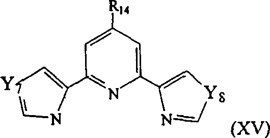 wherein R is14As described above, Y7And Y8Each independently is a sulfur atom or an oxygen atom.
Examples of suitable redox mediators also include, for example, osmium cations complexed with the following ligands: (a) two bidentate ligands, such as 2, 2 '-bipyridine, 1, 10-phenanthroline or derivatives thereof (the two ligands need not be the same), (b) one tridentate ligand, such as 2, 2', 2 "-terpyridine and 2, 6-bis (imidazol-2-yl) -pyridine, or (c) one bidentate ligand and one tridentate ligand. Suitable osmium transition metal complexes include, for example, [ (bpy)2OsLX]+/2+、[(dimet)2OsLX]+/2+、[(dmo)2OsLX]+/2+、[terOsLX2]0/+、[trimetOsLX2]0/+And [ (ter) (bpy)2LOs]2+/3+Wherein bpy is 2, 2 '-bipyridine, dimet is 4, 4' -dimethyl-2, 2 '-bipyridine, dmo is 4, 4' -dimethoxy-2, 2 '-bipyridine, ter is 2, 2': 6 ', 2 "-terpyridine, trimetet is 4, 4 ', 4" -trimethyl-2, 2 ': 6 ', 2' -terpyridine, L is a nitrogen-containing heterocyclic ligand and X is a halogen such as fluorine, chlorine or bromine.
The redox mediators typically exchange electrons rapidly with each other and with the electrode, enabling rapid oxidation and/or reduction of the complex. In general, iron complexes are more easily oxidized than ruthenium complexes, which are more easily oxidized than osmium complexes. In addition, the redox potential generally increases with the number of coordinating heterocycles; six-membered heterocycles are more capable of increasing the potential than five-membered rings, except in cases where the nitrogen of the coordinating metal is formally anionic. This is only true if the nitrogen in the ring is bound to its adjacent two carbon atoms by a single bond. If the nitrogen is anionic in form, the redox potential generally increases after coordination of the metal ion.
At least some diffusible redox mediators include one or more pyridine or imidazole functional groups. The imidazole functional group can also containother substituents and can be, for example, vinylimidazole, such as 1-vinylimidazole, or methylimidazole, such as 1-methylimidazole. Examples of suitable diffusible media may include [ Os (dmo)2(1-vinylimidazole) X]X、[Os(dmo)2(1-vinylimidazole) X]X2、[Os(dmo)2(imidazole) X]X、[Os(dmo)2(imidazole) X]X2、[Os(dmo)2(1-methylimidazole) X]X2And [ Os (dmo)2(methylimidazole) X]X2Wherein dmo is 4, 4 '-dimethoxy-2, 2' -bipyridine and X is halogen as described above.
Other osmium-containing redox mediators include [ Os ((methoxy)2Phenanthroline)2(N-methylimidazole) X]+/2+[ Os ((acetylamino)2Dipyridyl)2(L)X]+/2+Wherein L is a monodentate nitrogen-containing compound selected for improved potential (including but not limited to imidazole derivatives); and Os (Triterpyridine) (L)2Cl, wherein L is an aminopyridine, such as a dialkylaminopyridine; n-substituted imidazoles, such as N-methylimidazole; oxazole; a thiazole; or an alkoxypyridine, such as methoxypyridine. X is halogen as described above.
Osmium-free diffusible redox mediators include, for example, phenoxazines, such as 7-dimethylamino-1, 2-benzophenoxazine (meldola blue), 1, 2-benzophenoxazine, and nile blue, 3- β -naphthoyl (brilliant cresyl blue), Tetramethylphenylenediamine (TMPD), Dichloroindophenol (DCIP), N-methyldimethylphenylpyrazolone onium salts, such as phenazine dimethyl sulfate (PMS), N-methylphenazinium sulfate, and methoxyphenazine dimethyl sulfate, tetrazolium salts, such as tetrazolium blue or nitrotetrazolium blue, and phenothiazines, such as toluidine blue O.
Examples of other redox species include stable quinones and species containing quinoid structures in their oxidized state, such as nile blue and indophenol. Examples of suitablequinones include, for example, derivatives of naphthoquinone, phenoquinone, benzoquinone, cycloalkanequinone (naphthoquinone), and the like. Examples of the naphthoquinone derivative include juglone (i.e., 5-hydroxy-1, 4-naphthoquinone) and derivatives thereof, such as 2, 3-dichloro-5, 8-dihydroxy-1, 4-naphthoquinone, 2, 3-dimethyl-5, 8-dihydroxy-1, 4-naphthoquinone, 2-chloro-5, 8-dihydroxy-1, 4-naphthoquinone, 2, 3-methoxy-5-hydroxy-1, 4-naphthoquinone, and the like. Other examples include aminonaphthoquinones, for example, morpholinonaphthoquinones such as 2-chloro-3-morpholino-1, 4-naphthoquinone; piperidino naphthoquinones, such as 2-methyl 3-piperidino-1, 4-naphthoquinone; piperazine naphthoquinones, such as 2-ethoxy-3-piperazine-1, 4-naphthoquinone; and so on.
Suitable phenolquinone derivatives include, for example, coerulignone (i.e., 3 ', 5, 5' -tetramethoxydiphenoquinone) and derivatives thereof, such as 3, 3 ', 5, 5' -tetramethyldiphenoquinone, 3 ', 5, 5' -tetrahydroxydiphenoquinone, and the like.
Suitable benzoquinone derivatives include, for example, coenzyme Q0(i.e., 2, 3-dimethoxy-5-methyl-1, 4-benzoquinone) and derivatives thereof, such as 2,3, 5-trimethyl-1, 4-benzoquinone, 2, 3-dimethyl-5-methoxy-1, 4-benzoquinone, 2, 3-dimethyl-5-hydroxy-1, 4-benzoquinone, and the like.
Other suitable quinone derivatives include, for example, acenaphthenequinone and ubiquinone, such as coenzyme Q, including Q1、Q2、Q6、Q7、Q9And Q10。
Other suitable osmium-free diffusible redox mediators include, for example, taylor blue (i.e., 1, 9-dimethylmethylene blue), N' -diethylthiacyanine iodide, and thionine.
In another approach, the sensing layer 32 contains a non-leachable (i.e., non-releasable) redox mediator and is disposed on a portion ofthe working electrode 22. The non-leachable redox mediator can be, for example, a redox polymer (i.e., a polymer containing one or more redox species). Preferably, little or no non-leachable redox mediator is leached from working electrode 22 into the sample during the assay. The measurement process is generally less than about 5 minutes. The redox mediator of this embodiment may be bound or otherwise immobilized to working electrode 22 to prevent leaching of the mediator into the sample. The redox mediator may be bound or otherwise immobilized on the working electrode by known methods, such as, for example, formation of a polyionic bridge with an oppositely charged polyelectrolyte, covalent binding of the redox mediator to a polymer on the working electrode, entrapment of the redox mediator in a matrix having a high affinity for the redox mediator, or biological binding of the redox mediator to a compound bound on the working electrode. In one embodiment, a cation exchange membrane may be used to retain the anionic redox compound. Similarly, in another embodiment, an anion exchange membrane may be used to retain the cationic redox compound. In another embodiment for bioconjugation, the biotin-binding redox medium is capable of binding to avidin or streptavidin in a matrix adjacent to or immobilized on the working electrode. Another embodiment includes reacting a digoxin or digoxin redox mediator with an anti-digoxin in a matrix that is near or immobilized on the working electrode.
Preferred non-leachable redox mediators are redox polymers, such as polymeric transition metal compounds or complexes. The polymers used to form redox polymers typically contain nitrogen-containing heterocycles, such as pyridine, imidazole or derivatives thereof, as ligands for binding to the redox species. Suitable polymers that complex with redox species such as the transition metal complexes described above include, for example, polymers and copolymers of poly (1-vinylimidazole) (referred to as "PVI") and poly (4-vinylpyridine) (referred to as "PVP"), as well as polymers and copolymers of poly (acrylic acid) or polyacrylamide modified by the addition of pendant nitrogen-containing heterocycles such as pyridine and imidazole. Modification of poly (acrylic acid) s can be carried out by reacting at least a portion of the carboxylic acid functional groups with an aminoalkyl pyridine or an aminoalkyl imidazole, such as 4-ethylaminopyridine, to form an amide. Suitable copolymer substituents of PVI, PVP and poly (acrylic acid) include acrylonitrile, acrylamide, acrylhydrazide and substituted or quaternized 1-vinylimidazoles. The copolymers may be random or block copolymers.
The transition metal complex of the non-leachable redox polymer is typically covalently or coordinatively bound to the nitrogen-containing heterocycle (e.g., imidazole and/or pyridine ring) of the polymer. The transition metal complex may contain a vinyl functionality through which the complex may copolymerize. Suitable vinyl functionalities include, for example, vinyl heterocycles, amides, nitriles, carboxylic acids, sulfonic acids, or other polar vinyl compounds. An example of such a redox polymer is poly (vinylferrocene) or a derivative of poly (vinylferrocene) that is used to increase the swelling of the redox polymer in water.
Another class of redox polymers contains an oxygen ion-bonded by forming a polyionic bridgeAnd (5) transforming and reducing the seeds. Such media typically include charged polymers coupled to oppositely charged redox species. Examples of such redox polymers include negatively charged polymers such as Nafion coupled to a plurality of positively charged redox species such as osmium or ruthenium polypyridyl cations_(DuPont). Another example of an ionically-bound mediator is a positively-charged polymer such as quaternized poly (4-vinylpyridine) or poly (1-vinylimidazole) coupled to a negatively-charged redox speciessuch as ferricyanide or ferrocyanide. Preferred ionically bound redox species are multivalent charged, usually polyanionic, redox species bound in oppositely charged polymers.
Another suitable redox polymer includes a redox species coordinately bound to the polymer. For example, the mediator may be formed by the osmium, ruthenium, or cobalt 2, 2 '-bipyridine complex coordinated to poly (1-vinylimidazole) or poly (4-vinylpyridine) or by the copolymerization of a 4-vinyl-2, 2' -bipyridine osmium, ruthenium, or cobalt complex with 1-vinylimidazole or 4-vinylpyridine.
In general, the ratio of the osmium or ruthenium transition metal complex to the imidazole and/or pyridine group of the non-leachable redox polymer is from 1: 20 to 1: 1, preferably from 1: 15 to 1: 2, more preferably from 1: 10 to 1: 4. The redox potential is typically at least partially polymer dependent, and the order of redox potentials is poly (acrylic acid)<PVI<PVP.
Redox polymers can be immobilized on the electrode surface in a variety of ways. One method is adsorption immobilization. The method is particularly useful for relatively high molecular weight redox polymers. For example, the molecular weight of the polymer may be increased by crosslinking. The polymer of the redox polymer may contain functional groups such as hydrazide, amine, alcohol, heterocyclic nitrogen, vinyl, allyl, and carboxylic acid groups, which can be crosslinked with a crosslinking agent. These functional groups may be located on the polymer or one or more copolymers. In addition, functional groups may also be added by reactions such as quaternization. One example is the quaternization of PVP with bromoethylamine groups.
Suitable crosslinking agents include, for example, molecules containing two or more epoxide (e.g., poly (ethylene glycol) diglycidyl ether (PEGDGE)), aldehyde, aziridine, alkyl halide,and azide functional groups, or combinations thereof. When the polymer contains multiple acrylic functional groups, it can be crosslinked with a dithiol or polythiol; when containing multiple thiol functional groups, can crosslink with diacrylates or polyacrylates. Other examples of crosslinking agents include compounds that activate carboxylic acid or other acid functional groups for condensation with amines or other nitrogen compounds. These crosslinking agents include carbodiimides or compounds containing reactive N-hydroxysuccinimide or imidate functional groups. Other examples of cross-linking agents are quinones (e.g., tetrachlorobenzoquinone and tetracyanoquinodimethane) and cyanuric chloride. Other crosslinking agents may also be used. In certain embodiments, no additional crosslinking agent is required. Other descriptions and examples of crosslinking and crosslinking agents are set forth in U.S. Pat. No. 5,262,035; 5,262,305, respectively; 5,320,725, respectively; 5,264,104, respectively; 5,264,105, respectively; 5,356,786 and 5,593,852, incorporated herein by reference.
In another embodiment, the redox polymer is immobilized by functionalization of the electrode surface, followed by chemical bonding, typically covalently, of the redox polymer to a functional group on the electrode surface. An example of such immobilization starts with poly (4-vinylpyridine). Pyridine rings of polymers with reducible/oxidizable species such as [ Os (bpy)]2Cl]+/2+Partial complexation, where bpy is 2, 2' -bipyridine. A portion of the pyridine ring is quaternized by reaction with 2-bromoethylamine. The polymer is then crosslinked with a diepoxide such as poly (ethylene glycol) diglycidyl ether.
The carbon surface can be modified for redox polymer binding by electroreduction of, for example, a diazonium salt. One example is the reductive modification of diazonium salts formed after diazotization of p-aminobenzoic acid to modify carbon surfaces containing phenylcarboxylic acid functionality. These functional groups can be activated by carbodiimides such as 1-ethyl-3- (3-dimethylaminopropyl) carbodiimide hydrochloride (EDC). The activated functional group is combined with an amine functionalized redox couple, such as a quaternized osmium-containing redox polymer as described above or 2-aminoethyl ferrocene, to form a redox couple.
Similarly, gold and other metal surfaces can also be functionalized with, for example, amines such as cystamine, or with carboxylic acids such as thioctic acid. Redox pairs such as [ Os (bpy)]2(pyridine-4-carboxylic acid) Cl]0/+Can be activated by 1-ethyl-3- (3-dimethylaminopropyl) -carbodiimide hydrochloride (EDC) to form a reactive orthoacylisourea which can react with gold-bound amines to form amides. The carboxylic acid functionality of lipoic acid can be activated with EDC to bind polymer or protein amines to form amides.
When the enzyme used is PQQ glucose dehydrogenase or glucose oxidase, the preferred non-leachable redox mediator has a redox potential of about-300 mV to about +400mV relative to a Standard Calomel Electrode (SCE). The most preferred non-leachable redox mediator contains osmium redox centers having a redox potential of less than +100mV relative to SCE, more preferably less than 0mV relative to SCE, and most preferably near-150 mV relative to SCE.
In at least some instances, the redox mediator of the sensor is air-oxidizable. That is, the redox mediator may be oxidized by air, preferably such that at least 90% of the mediator is in an oxidized state prior to the addition of the sample to the sensor. The redox mediators oxidizable in air comprise a complex with two mono-, di-or polyalkoxy-2, 2' -bipyridine or mono-, di-or polyalkoxy-1, 10-phenanthroline ligandsOsmium cation, which need not be the same, and further complexed with polymers or otherligands containing pyridine and imidazole functional groups. In particular, Os [4, 4' -dimethoxy-2, 2' -bipyridine]2Cl+/+2Oxidation of about 90% or more in air can be achieved. Air oxidation of the redox mediator may occur when the redox mediator is a solid, such as when coated on the sensor in a dry state or stored. Furthermore, air oxidation of the redox mediator may also occur when the redox mediator is in solution, for example, before drying the solution on the sensor. Where the redox mediator is air-oxidized in solution, the solution containing the redox mediator may be stored for a period of time sufficient to air-oxidize the mediator prior to use of the solution in a manufacturing process.
Second electron transfer agent
In a preferred embodiment of the invention, the sensor comprises a redox mediator and a second electron transfer agent capable of transferring electrons to or from the redox mediator and the analyte. The second electron transfer agent may be diffusible or may be non-leachable (e.g., trapped in or coordinated, covalently or ionically bound to the redox polymer). One example of a suitable second electron transfer agent is an enzyme that catalyzes a reaction of the analyte. For example, when the analyte is glucose, glucose oxidase or glucose dehydrogenase, such as pyrroloquinoline quinone glucose dehydrogenase (PQQ), is used. Lactate oxidase plays this role when the analyte is lactic acid. Other enzymes may be used for other analytes. These enzymes catalyze the electrolysis of analytes by transferring electrons between the analyte and an electrode via a redox mediator. In certain embodiments, the second electron transfer agent is non-leachable, and more preferably is immobilized on the working electrode to prevent unwanted leaching of the agent into the sample. This is accomplished, for example, by crosslinking a non-leachable second electron transfer agent with a non-leachable redox mediator, thereby creating a sensing layer on the working electrode that contains non-leachable components. In other embodiments, the second electron transfer agent is diffusible (and may be placed on any surface of the sample chamber or in the sample). Counter electrode
In one embodiment of the invention, the working electrode 22 and the counter electrode 24 are placed opposite and face to face with each other, forming a face to face electrode pair as shown in fig. 1 and 3. In this preferred configuration, the sample chamber 26 is generally located between two electrodes. For such a face-to-face electrode structure, it is preferred that the electrodes are separated by a distance of no more than about 0.2mm (i.e., at least a portion of the working electrode is separated from a portion of the counter electrode by no more than 200 μm), preferably no more than 100 μm, and most preferably no more than 50 μm.
The electrodes need not be diametrically opposed to each other; they may be slightly offset. Moreover, the two electrodes need not be the same size. Preferably, counter electrode 24 is at least as large as the working surface of working electrode 22. The counter electrode 22 can also be formed with a tooth tip like a comb. Other configurations of the counter and working electrodes are also within the scope of the present invention. However, for this particular embodiment, the distance separating at least a portion of the working electrode from a portion of the counter electrode preferably does not exceed the limits described above.
As described above, FIGS. 11A, 11B, 11C show different embodiments of pairs of facing electrodes 22, 24. The overlapping area 21 of the two electrodes 22, 24 generally corresponds to the measurement area in which the sample is to be measured. Each of the electrodes 22, 24 is a conductive surface and acts as a capacitor plate. The measurement zone between the electrodes 22, 24 acts as a dielectric layer between the plates. Thus, a capacitance exists between the two electrodes 22, 24. This capacitance is a function of the size of the overlapping electrodes 22, 24, the spacing of the electrodes 22, 24, and the dielectric constant of the material between the electrodes 22, 24. Thus, if the size of the region 21 overlapping the electrodes 22, 24 and the dielectric constant of the substance (e.g. air or adsorbent) between the electrodes are known, the distance between the electrodes can be calculated to determine the volume of the measurement zone.
Fig. 11A shows an embodiment of the invention in which the electrodes 22, 24 are arranged face to face. In order to have uniform capacitance between similarly constructed analytical sensors having this particular sensor configuration, the positioning (i.e., the positioning of the two electrodes relative to one another) should be uniform. If the position of either electrode deviates in the x-y plane from the position shown in FIG. 11A, the size of the overlap region and thus the size of the capacitance will change. The same principle applies to the volume of the measurement zone.
Fig. 11B and 11C show other embodiments of the invention having electrodes 22, 24 arranged face-to-face. In these particular arrangements, the position of either electrode can be moved in the x-y plane at least some minimum distance relative to the other electrode without changes in capacitance and volume of the measurement volume occurring. In these electrode arrangements, each electrode 22, 24 includes an arm 122, 124, respectively, that overlaps the corresponding arm of the other electrode. The two arms 122, 124 are not parallel to each other (as shown in FIG. 11A); instead, the arms 122, 124 are placed at an intersection angle 123 greater than 0. In addition, the two arms 122, 124 extend beyond the overlap region 21 (i.e., each arm has an excess length corresponding to the difference between the respective length of the arms 222, 224 and the width 121 of the overlap region 21). With these electrode arrangements, there may be a degree of permissible inaccuracy in the positioning of the electrodes 22, 24, which does not change the capacitance of the electrode arrangement. By varying the angle 123 at which the arms 122, 124 are staggered and the excess length of the arms 122, 124 relative to the width 121 of the overlap region 21, a desired degree of permissible inaccuracy can be designed for the electrode arrangement. In general, the closer the arms 122, 124 are to being perpendicular (i.e., the angle 123 is 90 °), the greater the inaccuracy that is allowed. Likewise, the greater the length of each of the arms 122, 124 (which may be the same length or different lengths) that is exceeded relative to the width of the overlap region 21, the greater the inaccuracy that is permitted. Conversely, the greater the inaccuracy allowed, the larger the size of the electrode (width, thickness and angle of intersection 123 with another electrode for a particular electrode). Thus, the minimum distance that one electrode is offset from the other should be balanced with the amount of material required for the counter electrode. The intersection angle 123 is generally 5 to 90 degrees, preferably 30 to 90 degrees, more preferably 60 to 90 degrees. The ratio of the excess length of arms 122, 124 (corresponding to the difference between arm lengths 222, 224 and width 121 of overlap region 21) to the width of overlap region 21 is generally 0.1: 1 to 50: 1, preferably 1: 1 to 15: 1, more preferably 4: 1 to 10: 1.
In another embodiment of the invention, the two electrodes 22, 24 are coplanar as shown in FIG. 2. In this case, sample chamber 26 is in contact with two electrodes and is bound to opposite sides of the electrodes by an insulating inert matrix 30. Suitable materials for the inert matrix include insulating materials such as polyester.
Other configurations of the sensor of the present invention are possible. For example, the two electrodes may be formed on planes that form an angle with each other. One such structure has electrodes on the surfaces that form a right angle. Another possible configuration has the electrodes on a curved surface such as the inner surface of a tube. The working electrode and the counter electrode may be arranged so as to face each other from opposite sides of the tube. This is another example of a facing electrode pair. Further, the electrodes may be placed close to each other on the tube wall (e.g., one on top of the other or side-by-side).
In all configurations, the two electrodes must be configured such that they are not in direct electrical contact with each other to prevent shorting of the electrochemical sensor. This can be difficult to avoid when the facing electrodes are separated by an average of no more than about 100 μm.
When the electrodes face each other as shown in fig. 1 and 3, the electrodes can be separated by a spacer layer 28. The spacing layer is generally made of aninert insulating material, such as a pressure-sensitive adhesive, polyester, Mylar, chosen for its chemical inertnessTM、KevlarTMOr any other strong thin polymer film or thin polymer film such as TeflonTMAnd (3) a membrane. In addition to preventing contact between the electrodes, the spacer layer 28 generally serves as part of the boundary of the sample chamber 26, as shown in FIGS. 1-4. Other spacer layers include adhesive layers and double-sided adhesive tapes (e.g., a carrier film with adhesive on the opposite side of the film). Sample chamber
In another embodiment of the invention shown in FIG. 3, sample chamber 26 includes a larger volume than the areas proximate electrodes 22, 24. This configuration enables the provision of multiple electrodes in contact with one or more sample chambers, as shown in FIG. 5. In this embodiment, the size of the sample chamber 26 preferably may contain a volume of no more than about 1 μ l, preferably no more than about 0.5 μ l, and most preferably no more than about 0.25 μ l. The size of the measurement area (i.e., the area containing the volume of the sample to be measured) may generally contain a volume of no more than about 1. mu.l, preferably no more than about 0.5. mu.l, more preferably no more than about 0.25. mu.l, and most preferably no more than about 0.1. mu.l. One particularly useful configuration of this embodiment places the working electrode 22 and the counter electrode 24 face each other, as shown in fig. 3. In this embodiment, the measurement zone corresponding to the region containing the portion of the sample to be measured is the portion of sample chamber 26 defined by the working surface of the working electrode and located between the two opposing electrodes.
In both embodiments, the thickness of the sample chamber and the measurement zone generally corresponds to the thickness of spacer layer 28 (e.g., the distance between the electrodes in FIGS. 1 and 3, or the distance between the electrode and the inert substrate in FIG. 2). The spacer layer may be, for example, an adhesive or a double-sided adhesive tape or film. Preferably, the thickness is small to facilitate rapid electrolysis of the analyte, as more sample will be in contact with the electrode surface for a particular sample volume. In addition, the thin sample chamber helps to reduce errors in diffusion of analyte from other parts of the sample chamber into the measurement zone during analyte measurement, since the diffusion time is longer than the measurement time. The thickness of the sample chamber is generally no more than about 0.2 mm. Preferably, the thickness of the sample chamber is no more than about 0.1mm, and more preferably, the thickness of the sample chamber is about 0.05mm or less.
The sample chamber may be formed by other methods. Typical methods include embossing, scoring, or otherwise forming a groove in the substrate in which the working electrode 22 or counter electrode 24 is formed. Fig. 12A and 12B show one embodiment of such a structure. First, a conductive layer 100 is formed on an inert insulating base layer material 102. As described above, the conductive layer 100 may include gold, carbon, platinum, ruthenium dioxide, palladium, or other non-corrosive materials. The inert insulation base layer material 102 can be made of polyester, other polymers, or other insulating deformable materials. A recess 104 is then formed in the region of the insulating base layer material 102 such that at least a portion of the conductive layer 100 is contained in the recess 104. The groove 104 may be formed by a variety of techniques, including scoring, deforming, or otherwise impinging on the base material 102. Another exemplary method of forming the grooves includes embossing the base material 102. For example, the base layer material 102 may be contacted with an embossing roll or stamp having raised portions, such as perforated films or grooves, to form the grooves 104. In certain embodiments, the base layer material 102 may be heated to soften the material.
The grooves 104 may be circular, oval, rectangular, or any other regular or irregular shape. In addition, the recess 104 may also be formed as a trench extending along a portion of the base material 102. Conductive layer 100 may extend along the entire trench or a portion of the trench. For example, by depositing the sensing layer 32 only on portions of the conductive layer 100 within a particular area of the trench, the measurement area can be limited to a particular area within the trench. In addition, the measurement region may also be defined by placing the second electrode 107 only over a desired area of the first electrode 105.
At least a portion (and in some cases all) of conductive layer 100 is located in recess 104. This portion of conductive layer 100 may serve as a first electrode 105 (counter or working electrode). If conductive layer 100 forms the working electrode, sensing layer 32 can be formed over portions of conductive layer 100 by depositing a non-leachable redox mediator and/or a second electron transfer agent in recess 104, as shown in FIG. 12B. If a diffusible redox mediator or a second electron transfer agent is used, the diffusible material may be placed on either surface of the sample chamber or in the sample.
A second electrode 107 is then formed by depositing a second conductive layer on the second base material 106. The second electrode 107 is then placed in a face-to-face arrangement over the first electrode 105. Although not illustrated, if the redox mediator is not leachable, it will be understood that if first electrode 105 is used as a counter electrode, then sensing layer 32 will be deposited on second electrode 107, which is used as a working electrode. However, if the redox mediator is diffusible, the redox mediator may be disposed on any surface of the sample chamber or may be disposed in the sample.
In one embodiment, the second base material 106 is located on the first base material 102 and/or a portion of the un-recessed conductive layer 100 such that the second electrode 107 extends into the recess. In another embodiment, there is a spacer layer (not shown) between the first and second base materials 102, 106. In this embodiment, the second electrode 107 may or may not extend into the recess. In any case, neither the first nor the second electrode 105, 107 can be in contact, otherwise the two electrodes will be short-circuited.
The depth of the recess 104 and the volume of the part of the conductive layer 100, the sensing layer 32 and the second electrode 107 in the recess 104 determine the volume of the measurement area. Therefore, the prediction of the volume of the measurement region depends on the degree of uniformity in the formation of the grooves 104.
As shown in fig. 14A, in addition to the conductive layer 100, an adsorption layer 103, which will be described in detail below, may be deposited on the base material 102 before the grooves 104 are formed. As shown in fig. 14B, the adsorbent 103 may be scored, embossed, or otherwise deformed with the conductive layer 100 and the base material 102. In addition, the adsorbent 103 may also be deposited after the conductive layer 100 and the base material 102 are scored, embossed, or otherwise deformed to form the grooves 104.
In another exemplary method of making an analytical sensor, as shown in FIGS. 13A and 13B, a recess 114 is formed in a first base material 112. The grooves may be formed by scoring, embossing, etching (e.g., using photolithography or a laser to remove portions of the base material), or otherwise deforming or removing portions of base material 112. A first conductive layer 110 is then formed in the recess 114. Any of the conductive materials described above may be used. A preferred material is a conductive ink such as a conductive carbon ink available from Ercon, Inc. Conductive inks typically contain a metal or carbon dissolved or dispersed in a solvent or dispersant. When the solvent or dispersant is removed, the metal or carbon forms a conductive layer 110, which can serve as the first electrode 115. As described above, the second electrode 117 can be formed on the second base material 116 and over the recess 114. In embodiments containing a non-leachable redox mediator, as shown in FIG. 13B, a sensing layer 32 is formed on the first electrode 115 to form the working electrode. In other embodiments containing a non-leachable redox mediator, sensing layer 32 can be formed on second electrode 117, forming the working electrode. In addition, if a diffusible redox mediator is used, the working electrode need not include a sensing layer disposed thereon. In fact, because the redox mediator can be placed in the sample,no sensing layer is required, as is the case for the diffusible second electron transfer agent, if present. Any diffusible component may be placed on either surface of the sample chamber or placed in the sample independently. In addition, an adsorbent (not shown) may be formed in the groove, for example, on the first electrode 115.
Binders such as polyurethane resins, cellulose derivatives, elastomers (e.g., siloxanes, polymeric dihydrocarbons, or acrylonitrile-butadiene-styrene (ABS) resins), highly fluorinated polymers, and the like may also be included in the conductive ink. Curing the binder may increase the conductivity of the conductive layer 110, but curing is not required. The method of curing the adhesive may depend on the nature of the particular adhesive used. Some adhesives are cured by heat and/or ultraviolet light.
These configurations enable the formation of electrochemical sensors in which the volume of the measurement zone is dependent, at least in part, on the accuracy and repeatability of the recess 104. Embossing, laser etching, photo etching and other methods can be used to form the grooves 104 with repeatable dimensions of 200 μm or less. Adsorbent and process for producing the same
The sample chamber may be empty prior to placing the sample in the sample chamber. In addition, the sample chamber may also contain an adsorbent 34 to adsorb and hold the liquid sample during the assay. Suitable adsorbents include polyester, nylon, cellulose and cellulose derivatives such as nitrocellulose. The adsorbent facilitates the absorption of a small volume of sample by capillary action, which may supplement or preferably replace the capillary action of the sample chamber. Alternatively, some or all of the sample chamber walls may be covered with a surfactant such as Zonyl FSO.
In certain embodiments, the adsorbent is deposited witha liquid or slurry in which the adsorbent is dissolved or dispersed. The solvent or dispersant may then be removed from the liquid or slurry by heating or evaporation. Suitable adsorbents include, for example, cellulose or nylon powder dissolved or dispersed in a suitable solvent or dispersant such as water. The particular solvent or dispersant should also be compatible with the material of the working electrode 22 (e.g., the solvent or dispersant should not dissolve the electrode).
One of the most important functions of the adsorbent is to reduce the liquid volume required to fill the sample chamber and the corresponding assay region of the sensor. The actual volume of sample in the measurement zone depends in part on the size of the void space within the adsorbent. Suitable adsorbents generally include about 5% to about 50% void space. Preferably, the adsorbent comprises about 10% to about 25% void space.
It is advantageous to replace the liquid with an adsorbent. By adding the adsorbent, less sample is required to fill sample chamber 26. This reduces the volume of sample required for the assay and also reduces the time required to electrolyze the sample.
Methods other than sorbent capillary action can be used to deliver the sample to the sample chamber or the assay region. Examples of such delivery methods include applying pressure to the sample to force it into the sample chamber, drawing the sample into the sample chamber by creating a vacuum in the sample chamber using a pump or other vacuum-generating means, capillary action caused by the interfacial tension of the sample with the thin sample chamber walls, and capillary action of the adsorbent.
The sensor can also be used with a flowing sample stream. In this configuration, a sample stream is flowed through the sample chamber. The sample flow is periodically stopped and the analyte concentration is determined electrochemically, e.g., coulometrically. After the measurement, the flow was restarted, thereby removing the sample from the sensor. In addition, the sample may also flow through the sample chamber at a very low rate, such that all of the analyte is electrolyzed in transit, producing a current that depends only on the analyte concentration and flow rate.
Other packing materials may also be used to fill the measurement area and reduce the sample volume. For example, glass beads may be placed in the assay region to occupy space. Preferably, these filling materials are hydrophilic, so that body fluids can easily flow into the measurement area. In some cases, such as glass beads with a large surface area, these packing materials can also draw body fluid into the measurement zone due to their large surface area and hydrophilicity.
All sensor components are securely bonded together to ensure that the sample contacts the electrodes and that the sample chamber and assay region maintain the same volume. This is animportant consideration in coulometric analysis of samples, where a well-defined sample volume needs to be determined. One method of bonding the sensors together is shown in fig. 1 and 2. Two plates 38 are located at opposite ends of the sensor. The plates are typically made of an insulating material such as plastic. The plates are designed so that they can be secured together with the sensor between the two plates. Suitable fastening means include adhesives, clips, nuts and bolts, screws, and the like. Alternative sensor design
FIGS. 18A-18C show an alternative sensor design for forming a thin film sensor. The sensor includes a first substrate 500 on which a working electrode 502 is formed. The working electrode 502 includes a contact area 503 for connection to external electronics. Spacer layer 504 (FIG. 18B), such as an adhesive layer or double-sided adhesive tape, defines a channel 506, creating a sample chamber for the sensor. Two counter (or counter/reference) electrodes 510, 512 are formed on the second substrate 508 as shown in fig. 18C (inverted relative to fig. 18A and 18B to show the upper side of the electrodes). As described below, such a multiple pair electrode arrangement may have a fill indicator function. Each counter electrode 510, 512 has a contact area 511, 513 for contacting external electronics. The second substrate 508 is flipped over and placed on top of the first substrate 500 with the spacer layer 504 in between so that the working electrode 502 and the two counter electrodes 510, 512 face in the region of the trench 506.
In some cases, the counter electrode 510 closest to the entrance 514 of the trench 506 has at least twice the surface area of the other counter electrode 512 in the sample chamber, and may be at least 5 or 10 times larger. A non-leachable or diffusible redox mediator and/or a second electron transfer agent may be included on the first or second substrate 500,508 in the regions corresponding to the trenches 506 as described above.
The working and counter electrodes can be formed to cover the entire trench area (except for a small space between the two counter electrodes). In this embodiment, the sample chamber and the measurement zone are equally effective and have the same volume. In other embodiments, the assay region occupies, for example, 80% or 90% of the volume of the sample chamber. It will be appreciated that similar sensors can be constructed with one counter electrode or three or more counter electrodes. It should also be understood that there may be multiple working electrodes on the sensor.
One example of a method of fabricating a thin film sensor is described with respect to the sensor arrangement shown in fig. 18A-18C, and a variety of other sensor arrangements can be fabricated using this method, including those described above. A substrate, such as a plastic substrate, is provided. The substrate may be a single sheet or a continuous roll on a web. The substrate can be used to fabricate a single sensor or to fabricate multiple sensors. The multisensor can form a working electrode 1010 and a counter electrode 1020 on a substrate 1000. In certain embodiments, the substrate can be scored and folded such that the working electrode 1010 and the counter electrode 1020 are in close proximity to form a sensor. In certain embodiments, as shown in fig. 31A, the working electrodes 1010 (in individual sections, counter electrodes 1020) can be formed on the substrate 1000 in close proximity to each other to reduce waste, as shown in fig. 31A. In other embodiments, the working electrodes 1010 (in individual sections, counter electrode 1020) can be spatially separated, as shown in fig. 31B. The remainder of the method is described for the manufacture of multiple electrodes, but can be readily modified to form a single sensor.
Carbon or other electrode material (e.g., a metal such asgold or platinum) is formed on the substrate, providing a working electrode for each sensor. Carbon or other electrode materials can be deposited by a variety of methods, including printing carbon or metal inks, vapor deposition, and other methods.
Optionally, an insulating material, such as an insulating ink, can be formed against the working electrode to provide a plane along the path of movement of the sample fluid. The insulating material is adapted to create a smooth surface to facilitate filling by capillary action and/or to reduce the likelihood of air bubbles being trapped near the working electrode. Such insulating materials may be colored or colorless and may be formed on the substrate by printing or other techniques. The insulating material may be deposited before or after forming the working electrode.
One or more counter electrodes may be formed on the substrate. The counter electrode is formed by depositing carbon or other electrode material on the substrate. In one embodiment, the material of the counter electrode is an Ag/AgCl ink. The material of the counter electrode can be deposited by a variety of methods including printing or vapor deposition. In certain embodiments, the counter electrode is comprised of a different material, and/or one electrode is a counter electrode or a counter/reference electrode and one electrode is a reference or counter/reference electrode. In one embodiment, the working electrode is formed on a first half of the polymer sheet or web and the counter electrode is formed on the other half of the polymer sheet or web, such that the sheet or web can be folded to stack the working and counter electrodes in a face-to-face arrangement.
A second insulating material may be deposited adjacent to and/or between the counter electrodes to provide a plane along the path of movement of the sample fluid. This is particularly desirable in the region between the counter electrodes, which will be part of the sample chamber, to make the sample chamber surface planar. The insulating material is adapted to create a smooth surface to facilitate filling by capillary action and/or to reduce the likelihood of air bubbles being trapped near the working electrode. Such insulating materials may be colored or colorless and may be formed on the substrate by printing or other techniques. The insulating material may be deposited before or after forming the counter electrode.
A viscous spacer layer is formed on at least one of the substrate/working electrode and the substrate/counter electrode. The adhesive spacer layer may be a single layer of adhesive or a double-sided adhesive tape (e.g., a polymeric carrier film containing adhesive disposed on opposite sides) to form the channels, and the spacer layer, optionally with one or more release liners, may be cut (e.g., die cut) to remove the portions of the adhesive corresponding to the channels prior to disposing the spacer layer on the substrate. In addition, adhesive may also be printed or otherwise placed on the substrate in a pattern that defines the channel regions. The thickness of the spacer layer generally determines the spacing between the working and counter electrodes. When uniformity of spacing between sensors is necessary (e.g., for coulometry), uniformity of spacer layer thickness is important. Preferably, the thickness does not vary by more than ± 5% within a single sensor and/or between sensors in a batch.
A non-leachable or diffusible redox mediator and/or a second electron transfer agent is disposed on the substrate in at least the sample chamber region. If one or both of these components are non-leachable, the component or components must be placed on the working electrode. If either or both of these components are diffusible, the component may be placed on either surface of the substrate in the trench region. The redox mediator and/orthe second electron transfer agent can be placed on the substrate separately or together before or after the spacer layer is placed. The redox mediator and/or second electron transfer agent can be placed in a variety of ways including, for example, screen printing, ink jet printing, spraying, painting, striping along rows or columns of opposing and/or adjacent electrodes, and the like. The other ingredients may be placed separately or with the redox mediator and/or the second electron transfer agent, such as surfactants, polymers, polymer films, preservatives, binders, buffers, and cross-linking agents.
After the spacer layer, redox mediator, and second electron transfer agent are positioned, the substrate can be folded to form the sensor. The surfaces of the substrates are bonded together with the adhesive of the spacer layer. After surface bonding, the sensors can be cut by a variety of methods, including, for example, die cutting, slitting, or otherwise cutting away excess substrate and separating the sensors. In certain embodiments, a combination of these methods may be used. For example, some parts may be die cut, while the rest of the sensor may be slit. Alternatively, the sensor components (e.g., the components shown in FIGS. 18A and 18C) can be first cut from the substrate and then bonded together with a spacer layer adhesive to form the sensor.
The sensor embodiment shown in fig. 18A-18C is an example of a top-fill sensor. Fig. 19A-19C show another sensor configuration. This is a side-fill sensor. Fig. 19A shows a first substrate 520 having a working electrode 522. Fig. 19B shows the spacer layer 524 defining the trench 526. Fig. 19C (inverted relative to fig. 19A and 19B to show the electrodes) shows a second substrate 528 having three counter (or counter/reference) electrodes 530, 532, 534.
The sensor can be manufactured as described above. The symmetrical placement of the electrodes enables the sensor to be filled from either the left or right side to facilitate left-handed and right-handed persons. It will be appreciated, however, that similar sensor arrangements can be constructed with one, two or four or more counter electrodes and/or two or more working electrodes. The scallops 536, 538 may be formed by, for example, die cutting and, in at least some instances, may be precisely controlled to produce repeatable groove lengths. As another arrangement, the sides of the sensor may be straight, such that the sensor may be disconnected from the rest of the substrate and/or other sensors by cutting the substrate in a parallel direction using, for example, a gang robot blade system. 19A, 19B, and 19C, the edges of the sensor can define the edges of the sample chamber and/or the assay region. By precisely controlling the distance between the cutouts, changes in the volume of the sample chamber are generally reduced. In some cases, the cuts are preferably parallel to each other, as parallel cuts may be most easily reproducible.
20A, 20B, and 20C show another example of a side-filled sensor arrangement. Fig. 20A shows a first substrate 540 with a working electrode 542. Fig. 20B shows the spacer layer 544 defining the trench 546. Fig. 20C (flipped relative to fig. 20A and 20B) shows a second substrate 548 having three counter (or counter/reference) electrodes 550, 552, 554.
Fig. 21A, 21B and 21C show another example of a top-filled sensor arrangement. Fig. 21A shows a first substrate 560 with a working electrode 562. Figure 21B shows the spacer layer 564 defining the trench 566. FIG. 21C (inverted relative to FIGS. 21A and 21B) shows a second membrane substrate 568 having two counter (or counter/reference) electrodes 570, 572. There is a vent 574 (shown in shaded area in fig. 21C) through the second substrate. In the embodiment shown, vent 574 is formed only through substrate 568 having the counterelectrode and optional spacer layer 564. In this embodiment, the vent holes may be formed, for example, by die cutting a portion of the substrate. This die cutting cuts away a portion of at least one of the counter electrodes, but a sufficient number of counter electrodes should be in contact with the sample in the channel and electrically connected to the contact area at the other end of the sensor. In another embodiment, the vent 574 can be formed through all layers or through a first substrate rather than a second substrate.
Fig. 22A, 22B and 22C show another embodiment having a different shape. The sensor includes a first substrate 579 having at least one working electrode 580, as shown in FIG. 22A. The sensor also includes a spacer layer 581 in which a groove 582 is formed in the spacer layer 581, as shown in fig. 22B. The sensor also includes a second substrate 583 having two counter electrodes 584, 585, as shown in fig. 22C (flipped over with respect to fig. 22A and 22B). The vent 586 is typically cut through all layers and extends out one side of the sensor. In certain embodiments, the vent and front 587 of the sensor are cut simultaneously to a repeatable distance between the vent and front 587 of the sensor, resulting in a repeatable length for the channel 582 and working electrode 580. FIGS. 22A, 22B and 22C also show another feature that can be used with any sensor arrangement. A pocket 588 may be formed at the injection port of the channel 582 to facilitate the drawing of fluid into the sensor. In this configuration, the liquid has no flat surface, but rather a serrated surface that facilitates capillary or capillary filling of the channel (i.e., sample chamber). This configuration may also reduce the likelihood of a user of the sensor blocking the channel during collection of a sample. A tip that is laterally aligned with the skin pressure sensor may occlude the planar sensor.
23A, 23B, and 23C show another example of a side-filled sensor arrangement. Fig. 23A shows a first substrate 640 having a working electrode 642. Fig. 23B shows a spacer layer 644 that defines a trench 646. Fig. 23C (inverted relative to fig. 23A and 23B) shows a second substrate 648 with three counter (or counter/reference) electrodes 650, 652, 654. The sensor may be formed by making a straight cut into the substrate. As shown in fig. 31A, these sensors can be made adjacent to each other, which can result in less waste. The length of groove 646 is generally defined by two parallel cuts along sensor sides 656, 658. Another optional processing advantage, particularly when the sensors are adjacent to one another, is the ability to place these components in the channels by adding a continuous flow of redox mediator and/or second transfer agent along the rows or columns of adjacent sensors. This may result in higher efficiency and less waste of redox mediator and/or second electron transfer agent than other techniques such as placing these components individually in a single trench.
24A, 24B, and 24C show another sensor configuration. The sensor includes a first substrate 600 having at least one working electrode 602, as shown in FIG. 24A. The sensor also includes a spacer layer 604 forming a trench 606 in the spacer layer 604, as shown in FIG. 24B. The sensor also includes a second substrate 608 having two counter (or counter/reference) electrodes 610, 612, as shown in fig. 24C (flipped over with respect to fig. 24A and 24B). The sensor may also include, for example, an indicator, such as a groove 614 or extension 616 of the sensor body, that indicates to the user which side should be placed adjacent to the sample. This is particularly important when the sensor reading is correct only when the sample is coming in from a particular side.
Fig. 24B also shows another optional component that may be used in any sensor configuration. In this illustration, the sample chamber 606 is notformed by a straight line, but rather has an expansion region 618 within the sample chamber. This allows for a larger sample chamber without having to form a larger opening. The expanded region can be any shape, including circular, square, rectangular, and other regular and irregular shapes.
FIG. 25 is an example of an assembled sensor showing another sensor arrangement for a side-fill sensor 620. The sensor includes an extension 622 of a sensor body 624 that indicates to a user where the opening of a sample chamber 626 is located.
Fig. 32 shows an optional component, which is a side view of the sensor from the inside of the meter. Fig. 32 shows a first substrate 1120 and a second substrate 1130 extending into the meter from the rest of the sensor 1100 (i.e., the portion 1140 is recessed relative to the substrates 1120 and 1130 in fig. 32). FIGS. 18A-18C and 24A-24C show examples of such a configuration. In general, sensor 1100 is connected to meter 1110, which includes contact pads (not shown) that contact electrode contact areas (e.g., areas 503, 511, and 513 in fig. 18A and 18C) of sensor 1100. The end of the sensor 1100 having the contact area can be slid into the meter 1110. It is generally important that the contact pads of meter 1110 contact the correct contact areas of the sensor so that the working and counter electrodes are properly connected to the meter. In some cases, the sensor is configured such that the contact area of the working electrode on the first substrate 1120 has a width w1 that is different from the width w2 of the contact area of the second substrate 1130 with the counter electrode. Examples of electrode configurations having such a structure are shown in fig. 18A to 18C and 24A to 24C. To ensure that the sensor 1100 is properly inserted into the meter 1110, the meter 1110 can include raised regions 1140 that can prevent or inhibit the sensor from being inserted in an improper orientation. Forexample, the width w2 of the contact region of the second substrate 1130 may be wider than the width w1 of the contact region of the first substrate 1120, as shown in FIG. 32. In this case, the location of the raised region 1140 allows the sensor 1100 to be slid into the meter so that the first substrate 1120 is proximate to the surface 1150 from which the convex surface 1140 protrudes, but prevents or blocks the second substrate 1130 from being proximate to the surface 1150 from which the convex surface 1140 protrudes. Objects other than a convex surface can also be used to guide the user in placing the sensor correctly in the meter. Integrated sample acquisition and analyte determination device
Various methods are known in the art for obtaining small samples and/or for transporting them from within the body to a sensor. This includes, for example, U.S. patent nos. 5,746,217, 5,820,570, 5857983, and 5879311, which are incorporated herein by reference. The sensors of the present invention may be adapted for use in any of these sample acquisition and/or delivery methods.
In a preferred embodiment of the present invention, an analyte-determining device 52 constructed in accordance with the principles of the present invention includes a sensor 20 as described above coupled to a sample acquisition device 50 to form an integrated sampling and determination device. The sample acquiring device 50 shown in fig. 6 comprises, for example, a skin puncturing element 54, such as a lancet, to which is attached a resiliently flexible reed 56 (or other similar device, such as a spring) which can be used to inject the lancet into the skin of a patient to obtain blood flow.
The spring reed 56 is then released, retracting the skin puncturing assembly 54. Blood exiting the area of skin punctured by component 54 can then be transported by capillary action, e.g., of sorbent 34, to sensor 20 for analysis of the analyte. The analytedetermining means 52 may then be placed in a reader (not shown) which connects a coulometer or other electrochemical analysis device to the electrode contacts 23, 25 to determine the concentration of the analyte by an electroanalytical method. Preferably, the analyte determining means is packaged in a reader when connected to a coulometer or other electrochemical analysis device.
In a preferred embodiment, the integrated sample acquisition and analyte measurement device comprises a lancing device that holds a lancet in combination with a measurement reed. The puncturing device preferably requires activation of firing. The risk of inadvertent firing of the lancet is minimized by requiring the user to screw the device prior to use.
Preferably, the puncturing device is automatically triggered when the puncturing device is pressed against the skin with sufficient pressure. It is known in the art that when pressure is applied around the site where the pores are created in the skin, a larger sample of bodily fluid, such as blood or interstitial fluid, can be expressed. See, for example, the above-mentioned U.S. patents to Integ and Amira, and the tip designs of lancing devices sold by Becton Dickenson. All of these lancing devices have a protruding ring surrounding the cutting site for generating pressure to express the sample out of the wound. However, all of these devices require the user to apply sufficient pressure to the wound site to express the sample, and all of the lancing devices are actuated by the user with a push button. The design of suitable pressure triggers is well known to those skilled in the art.
Preferably, the lancing device also allows the user to adjust the depth to which the lancet penetrates the skin. These devices are already commercially available from companies such as Boehringer Mannheim and Palco. This feature allows the user to adjust the lancing device to account for differences in skin thickness, skin durability, and pain sensitivity between different parts of the body and between different users.
In a more preferred embodiment, the lancing device and the test reader are integrated into a single device. To operate the device, the user simply inserts the disposable cartridge containing the measurement reed and lancing device into the integrated device, screws the lancing device, activates it by pressing against the skin, and reads the measurement. Such an integrated lancing device and test reader simplifies the testing procedure for the user and minimizes the disposal of bodily fluids.
Fig. 26 shows another example of an integrated sample acquisition and sensor device 700. The integrated sample acquisition and sensor device 700 includes a housing 702, a skin piercing assembly (e.g., lancet) 704, a puncture/collection aperture 706, a disposable sensor 708, a sensor guide 710, and a skin piercing assembly retraction mechanism 714. The device 700 can be designed for repeated use (e.g., to make the skin puncturing assembly 704 and the sensor 708 removable) or for single use.
The chassis 702 may be made from a variety of materials including metal and plastic. The chassis 702 may include a hinge 716 or other structure (e.g., adhesive or interlocking portions) to join the portions of the chassis together.
A puncture/collection hole 706 is provided in housing 702 such that skin puncturing assembly 704 protrudes through hole 706 and penetrates the skin of a user, thereby obtaining blood flow (or other bodily fluid). The sensor 708 may also extend to the edge of or beyond the aperture 706 for collection of blood (or other bodily fluid) through an opening (not shown) in the sensor tip. This may allow a user to puncture the skin to collect a fluid sample without moving the device 700. In addition, the skin puncturing assembly 704 and the sensor 708 can have different apertures. Sensor guides may be configured in the chassis 702 or added to the chassis to guide the sensors 708 into position as they are inserted through the chassis and/or to support the sensors in the chassis and during sample collection.
The skin puncturing assembly 704 may include an actuator (not shown) that includes a mechanism for screwing and releasing the skin puncturing assembly 704, or the skin puncturing assembly may be externally actuated. For example, a sensor reader (not shown) or other device may be coupled to the sample acquisition and sensor device, the sensor reader, or other device including mechanisms that may screw and/or release the skin puncturing assembly 704.
The retraction mechanism 714 of the device 700 may be, for example, a spring or resilient metal spring that retracts the skin puncturing assembly 704 into the housing after penetrating the user's skin. This may allow for unimpeded collection of the sample and/or prevent re-penetration of the user's or other person's skin, thereby reducing or preventing contamination or infection from transfer of bodily fluids or other harmful agents. In addition, retraction of the skin puncturing assembly can also be accomplished with an external device or instrument.
One example of an operation includes screwing skin puncturing assembly 704 and then releasing skin puncturing assembly 704 such that it extends out of housing 702 through puncturing/collecting aperture 706 and penetrates the skin of the user. Skin puncturing assembly 704 optionally pushes the sensor off of the positive rail when extended out of the chassis. Skin puncturing assembly 704 is retracted within chassis 702 with retraction mechanism 714. After retraction of the skin puncturing assembly, the sensor collects sample fluid from the punctured skin through the opening in the sensor 708.
If a sensor reader is used, the sensor reader may also be configured to be connected to the contact terminals of the sensor. The sensor reader may include a potentiostat or other component to provide the potential and/or current to the electrodes of the sensor. The sensor reader may also include a processor (e.g., a microprocessor or hardware) for determining the analyte concentration from the sensor signal. The sensor reader may include a display or port for connecting the display to the sensor. The display may display the sensor signal and/or results determined from the sensor signal including, for example, the analyte concentration, the rate of change of the analyte concentration, and/or the analyte concentration exceeding a threshold (e.g., indicating hypoglycemia or hyperglycemia). The sensor reader may be used with an integrated sample acquisition and sensor device, or the sensor reader may be used with a sensor alone, and the contact zone of the sensor may be coupled to the contact zone of the sensor reader. Operation of the sensor
An electrochemical sensor of the present invention may operate with or without an applied potential. In one embodiment, the electrochemical reaction occurs naturally and no potential needs to be applied between the working electrode and the counter electrode.
In another embodiment, an electrical potential is applied between the working electrode and the counter electrode. But the potential need not remain constant. The magnitude of the required potential depends on the redox mediator. The potentials at which the electrodes equilibrate themselves, or at which the electrodes are biased by the application of an external source, and at which the analyte electrolyzes, are generally such that the electrochemical reaction is toward or near completion, but preferably not sufficiently oxidized to result in significant interference with the electrochemical reaction, such as urate, ascorbic acid,and acetaminophen, which can affect the signal being measured. For non-leachable redox mediators, the potential is typically about-350 mV to about +400mV versus a Standard Calomel Electrode (SCE). Preferably, the redox mediator has a potential of less than +100mV, more preferably less than 0mV on ground, and most preferably about-150 mV on ground relative to SCE.
When an external potential is applied, it may be applied before or after the sample is added to the sample chamber. If the measurement zone comprises only a portion of the sample chamber, it is preferred that the potential be applied after the sample has come to rest in the sample chamber to prevent electrolysis of the sample passing through the measurement zone when the sample chamber is full. Furthermore, if the assay region comprises most or all of the sample chamber, the potential may optionally be applied before or during filling of the sample chamber without affecting the accuracy of the assay. When a potential is applied and the sample is in the assay region, a current will flow between the working electrode and the counter electrode. The current is at least partially a result of electrolysis of the analyte in the sample. This electrochemical reaction takes place by means of a redox mediator and optionally a second electron transfer agent. For a variety of biomolecules B, this process can be represented by the following equation:
As an example, a sensor of the present invention is based on a glucose molecule in combination with two [ Os (dmo-phen)2(NMI)Cl]2+Reaction of a cation, where dmo-phen is 4, 8-dimethoxyphenanthroline and NMI is N-methylimidazole, in the presence of glucose oxidase to yield two [ Os (dmo-phen)2(NMI)Cl]+A cation, two protons and an oxidation product of glucose, for example, gluconolactone or another ketone. By mixing[Os(dmo-phen)2(NMI)Cl]+Electro-oxidation of cations to[Os(dmo-phen)2(NMI)Cl]2+The cation and the total charge transferred are measured to determine the amount of glucose present.
Those skilled in the art will recognize that there are many different reactions that can produce the same result; i.e., electrolysis of the analyte through a reaction pathway involving a redox mediator. Equations (1) and (2) are non-limiting examples of such reactions.
Coulomb method
In a preferred embodiment of the invention, the concentration of the analyte is determined coulometrically. This measurement technique uses current magnitude obtained at intervals during the measurement to measure the concentration of the analyte. These current magnitudes are integrated over time to obtain the magnitude Q of the charge transferred to or from the electrodes. The concentration of the analyte (CA) is then calculated using Q by the following equation (when the redox mediator is not leachable):
CAQ/nFV (3a) where n is the number of electron equivalents required to electrolyze the analyte, F is the faraday constant (about 96500 coulombs per equivalent), and V is the sample volume in the measurement zone. When using a diffusible medium, the analyte concentration can be obtained from the following equation:
CA=(Qtot-Qback) /nFV (3b) wherein QtotIs the total charge transferred during the measurement, QbackIs the amount of charge transferred that is not caused by the analyte, e.g., the charge shuttled by the diffusible medium between the working electrode and the counter electrode. In at least some instances, the sensor is configured such that the background charge is at most 5 times the magnitude of the charge generated electrolytically by the amount of analyte. Preferably, the background signal is at most 200%, 100%, 50%, 25%, 10% or 5% of the charge generated by electrolysis of the analyte.
One example of a method of determining the ratio of background signal to signal generated by electrolysis of an analyte is described below for a facing electrode pair. If the applied potential is not sufficient to shuttle the redox mediator, the charge generated by the shuttling of the redox mediator can be expressed by the following equation:
Qback=(AFDMCM/d)(tnM) Wherein a is the area of the working electrode; f is the Faraday constant (96500 Coulomb/equivalent); dMIs the effective diffusion coefficient of the redox mediator; cMIs the concentration of the redox mediator in the measurement zone; d is the spacing of the facing electrodes; t is the length of the measurement time; n isMIs the acquisition or loss of a redox mediatorThe number of electrons of (c).
In addition, when the electro-oxidation of the analyte is completed by about 90% during the measurement, the charge of the analyte such as glucose can be expressed by the following equation:
QG=Ad(0.90)CGnGf where a is the area of the working electrode; d is the spacing of the facing electrodes; cGIs the concentration of glucose; n is the number of electrons required to electrolyze the analyte (e.g., 2 electrons per glucose molecule); f is the Faraday constant. When C is presentGIs 5mM (or 5X 10)-6mol/cm3) T is 60 seconds, nGIs 2, nMAt 1, the ratio of the charge generated by the redox mediator to the charge generated by electrolysis of the analyte can be expressed by the following equation: qBack/QG=(DMCM/d2)(tnM/(0.9nGCG))=(DMCM/d2)×(6.7×106) For example, if QBack/QGA ratio of (D) is 5, (D)MCM)/d2Is 7.5X 10⁻⁷mol/(cm3sec). Also for example, if QBack/QGIs 1, then (D)MCM)/d2Is 1.5X 10⁻⁷mol/(cm3sec). As another example, if the ratio is 0.1, (D) isMCM)/d2Is 1.5X 10⁻⁸mol/(cm3sec). Thus, depending on the desired ratio, D may be selectedM、CMAnd d constructing the sensor to have the desired ratio. For example, the concentration of the redox mediator can be reduced (i.e., C can be reduced)M). In addition, for example, by placing a barrier layer in the flow of the diffusible medium to the counter electrode (i.e., reducing the effective diffusion coefficient-D of the redox mediator)M) Diffusion of the redox mediator may be reduced. Other sensor configurations are also suitable for controlling the ratio of background signal to analyte-generated signal, and will be described below.
Background charge Q can be resolved in a variety of waysback. For example, Q can be achieved by using only a limited amount of diffusible redox mediator, by adding a membrane over the counter electrode that limits diffusion of the redox mediator to the counter electrode, or by creating a relatively small potential difference between the working electrode and the counter electrodebackAnd becomes smaller. Adapted to reduce QbackOther examples of sensor configurations and methods of (a) include those already described, such as where the redox mediator reaction rate is significantly faster at the working electrode than at the counter electrode; fixing a redox mediator on the working electrode; the redox mediator is fixed on the counter electrode or the counter/reference electrode after reacting at the counter electrode or the counter/reference electrode; or a sensor that slows the diffusion of the redox mediator.
In addition, the sensors may be calibrated individually or in batches, determining a correction curve or QbackThe value of (c). Another option includes a second electrode pair that lacks a component necessary for electrolysis of the analyte, such as a second electron transfer agent, such that a complete signal generated by the second electrode pair corresponds to Qback。
For coulometry, at least 20% of the analyte electrolyzes. Preferably at least 50%, more preferably at least 80%, still more preferably at least 90% of the analyte is electrolyzed. In one embodiment of the invention, the analyte is completely or almost completely electrolyzed. The charge can then be calculated from the current magnitude obtained in the electrochemical reaction and the analyte concentration determined using equation (3a) or (3 b). Completion of the electrochemical reaction is generally indicated when the current reaches a steady state value. This indicates that all or almost all of the analyte has been electrolyzed. For such assays, typically at least 90% of the analyte is electrolyzed, preferably at least 95% of the analyte is electrolyzed, more preferably at least 99% of the analyte is electrolyzed.
For coulometry, rapid electrolysis of the analyte is generally desired. The speed of the electrochemical reaction depends on several factors, including the potential applied between the electrodes and the kinetics of reactions (1) and (2). (other important factors include the size of the assay region and the presence of adsorbents in the assay region.) generally, the greater the potential, the greater the current through the cell (up to the transport ceiling), and thus generally the faster the reaction will occur. However, if the potential is too large, other electrochemical reactions can produce significant errors in the assay. The potential between the electrodes and the specific redox mediator and optional second electron transfer agent are generally selected to allow nearly complete electrolysis of the analyte in less than 5 minutes, depending on the desired analyte concentration in the sample. Preferably, the analyte is almost completely electrolyzed within about 2 minutes, more preferably within about 1 minute.
In another embodiment of the invention, the analyte is only partially electrolyzed. The current is measured during part of the reaction and then extrapolated using mathematical methods known to those skilled in the art to determine a current curve for complete or nearly complete electrolysis of the analyte. If the analyte is completely or almost completely electrolyzed, the integral of the curve yields the amount of charge delivered and the concentration of the analyte is calculated using equation (3a) or (3 b).
Although coulometry has the disadvantage of requiring a known volume of sample to be measured, coulometry is a preferred technique for analyzing small amounts of sample because it has the following advantages, for example: no temperature dependence on the assay, no enzyme activity dependence on the assay, no redox mediator activity dependence on the assay, no error in the assay of analyte depletion in the sample. As noted above, coulometry is a method of determining the amount of charge transferred or expected to be transferred during complete or nearly complete electrolysis of an analyte. One coulometry technique involves the electrolysis of an analyte at a working electrode and the measurement of the current generated between the working electrode and a counter electrode two or more times during the electrolysis process. Electrolysis is complete when the current reaches steady state. The charge for the electrolysis of the sample is then calculated by integrating the measured current over time and taking into account any background signal. Since the charge is directly related to the amount of analyte in the sample, the assay is temperature independent. In addition, enzyme activity does not affect the value of the assay, but only the time required to obtain a quantitative value (i.e., less active enzyme requires longer time to achieve complete electrolysis of the sample), so that the decay of the enzyme over time does not render the analyte concentration determination inaccurate. Finally, the consumption of the analyte in the sample by electrolysis is not the cause of error, but is the goal of the technique. (however, if the electrolysis curve is extrapolated from a partial electrolysis curve according to well-known electrochemical principles, the analyte need not be completely electrolyzed)
Non-coulometric measurements
While coulometry is useful, one skilled in the art will recognize that sensors of the invention can also utilize potentiometry, amperometry, voltammetry, and other electrochemical techniques to determine the concentration of an analyte in a sample. These non-coulometric methods do not yield values that are likely to be temperature dependent as coulometric methods.
In addition, the quantities obtained by these non-coulometric electrochemical techniques can be sensitive to the amount of active enzyme in the sensor. If the enzyme is inactivated or decayed over time, the resulting magnitude can be affected. This can limit the shelf life of these sensors unless the enzyme is very stable.
Finally, if a substantial portion of the analyte and/or redox mediator is electrolyzed during the assay, the magnitude obtained by non-coulometric electrochemical techniques, such as steady-state amperometry, can be adversely affected. Accurate steady state quantities may not be available unless there is sufficient analyte and/or redox mediator such that only a relatively small portion of the analyte and/or redox mediator is electrolyzed during the assay. This may be promising in a sample volume of no more than 1 μ Ι.
In some cases it may be desirable to utilize non-coulometric assays such as amperometric or potentiometric techniques. For example, coulometry requires that the volume of the sample to be measured is known. Moreover, the sample volume in the measurement area of a small volume sensor (i.e., no more than 1 microliter) can be difficult to accurately reproduce if manufacturing tolerances for one or more dimensions of the measurement area have significant variations.
As described for coulometry, in amperometric or potentiometric assays on no more than 1 μ Ι of sample in a thin-layer electrochemical cell, the background signal generated by the shuttling of the redox mediator between the electrodes may be a source of assay error. It is generally desirable that the medium is shuttled between a pair of electrodes no more than 10 times, preferably no more than 1 time, more preferably no more than 0.1 times, during the assay. To reduce background signal induced errors, methods and sensor configurations similar, and in some cases identical, to those used for coulometry may be used. Examples include all of the methods and structures described above, such as performing an electrochemical assay at a relatively low applied potential, electro-oxidizing an analyte at a negative applied potential, or electro-reducing an analyte at a positive applied potential, using a counter electrode where the redox mediator reacts relatively slowly (particularly compared to the reaction of the redox mediator at the working electrode), and/or using a redox mediator that undergoes an irreversible reaction at the counter electrode. Other examples are discussed below.
As described for coulometry, the sensor is preferably designed and operated so that the background signal is at most 5 times the size of the signal generated by electrolysis of the analyte. Preferably, the background signal is at most 200%, 100%, 50%, 25%, 10% or 5% of the signal generated by electrolysis of the amount of analyte. The amount of analyte compared to the background signal is described above in the section entitled "background signal". For amperometry, the signal produced by electrolysis of a quantity of analyte is the current at which the measurement is made. For potentiometric assays, the signal generated by electrolysis of a quantity of analyte is the potential at which the assay is performed.
Under a specific set of operating conditions, e.g. temperature, cell geometry and electrode size, background current value IbackThe following expression is used to derive:
iback=KCMDMd wherein: k is a proportionality constant; cMIs the concentration of the medium in the measurement area;DMIs the effective diffusion coefficient of the medium in the assay region under normal operating conditions; d is the distance between the electrodes.
Background current reduction is desirable for non-coulometric assays. The above-described sensor configurations and methods are generally useful, including, for example, using low concentrations of redox mediators and/or second electron transfer agents (e.g., enzymes) relative to the concentration of the analyte, and/or using larger redox mediators having relatively lower effective diffusion constants. Other useful methods described above include methods of reducing diffusion of the redox mediator, for example, placing a barrier (e.g., a charged or polar barrier) for the flow of the diffusible mediator, or using a redox mediator with a relatively low effective diffusion constant.
In some cases, the effective diffusion coefficient does not exceed about 1 × 10⁻⁶cm2Sec, not more than about 1 x 10⁻⁷cm2Sec, or not more than about 1X 10⁻⁸cm2And/sec. And in some cases, CMDM(ii) a product of (concentration of redox mediator multiplied by effective diffusion coefficient) no more than about 1X 10-12mol/cm sec of not more than about 1X 10-13mol/cm sec, or not more than about 1X 10-14mol/cm·sec。
Specific examples of glucose amperometry measurements performed for 60 seconds, with a measurement period of 10%, are provided belowThe glucose was electrolyzed in a 1. mu.l cell with a face-to-face electrode spacing of d 0.01 cm. If the determination is carried out under the following conditions: glucose concentration CG5mM (or 5X 10)-6mol/cm3) Area A is 0.1cm2Number of electrons n from the redox mediatorM1, number of electrons n from glucoseGThe background current generated by the redox mediator and glucose was then determined as follows.
iback=AFnMDMCM/d
=(0.1)(96500)(1)DMCM/(0.01)
=9.65×10⁵CMDM
iG=nGAd(0.1)FCG/t
=(2)(0.01)(0.1)(96500)(5×10⁻⁶)/60=1.61μamps
Therefore, if iback/iGWhen the result is 5, then CMDMIs equal to 8.34 × 10⁻¹²mol/cm2Sec. Another example is if iback/iGWhen the value is 0.5, then CMDMIs equal to 8.34 × 10⁻¹³mol/cm2Sec. In addition, if iback/iGWhen the ratio is 0.05, then CMDMIs equal to 8.34 × 10⁻¹⁴mol/cm2.sec。
In certain amperometric or potentiometric embodiments, redox mediator cycling is reduced by separating the working electrode from the counter or counter/reference electrode such that the redox mediator diffuses no more than, for example, the distance between the electrodes during the assay. Redox mediator mass energy diffusion equal to (D)Mt)1/2A distance of (2), wherein DMIs the effective diffusion coefficient of the medium between the electrodes, and t is the time. For a measurement time of 30 seconds and an effective diffusion coefficient of 10-5~10-4cm2For a redox mediator/sec, the electrodes should be separated by at least 100 μm, preferably at least 200 μm, more preferably at least 400 μm.
One way to separate the working electrode from the counter electrode is to use a thicker spacer layer between the electrodes. Fig. 27 shows an alternative method. In this embodiment, working electrode 740 is disposed on a first substrate 742 and counter electrode 744 is disposed on a second substrate 746 (alternatively,the electrodes may be disposed on the same substrate). Working electrode 742 and counter electrode 744 are offset such that the effective distance d between the two electrodes is greater than the thickness w of spacer layer 748. In one embodiment, the spacing d of the electrodes is chosen to be 25-1000 μm, 50-500 μm or 100-250 μm.
In addition, for steady state amperometry and potentiometry, the background signal can be controlled by limiting the rate of electrolysis to a rate low enough to prevent the analyte concentration from decreasing by more than about 20%, 10%, or 5% or less during the measurement period, e.g., 30 seconds, 1 minute, 5 minutes, or 10 minutes. In some cases, the concentration or activity of the second electron transfer agent may be reduced, and/or the area of the working electrode may be reduced, in order to control the rate of electrolysis.
For example, the second electron transfer agent may be an enzyme, and the enzyme activity may be a limiting factor in the rate of electrolysis. For example, if the analyte concentration is 5mM glucose (i.e., 5X 10)-9mol/. mu.l glucose) and there will be no more than 10% glucose (5X 10) during the 30 second measurement-10Molar) is electrically oxidized, the current should not exceed 3.3X 10 for 1. mu.l-6In amperes. One unit of enzyme is the amount of enzyme that catalyzes the electrolysis of 1. mu. mol of substrate in HEPES buffer at pH7.4 and 37 ℃ in 60 seconds. Thus, it can be produced every 1cm for glucose3(i.e. 1mL) can reach 3.3X 10⁻³An ampere current. Therefore, the maximum amount of enzyme used in a sensor in which the degree of electrolysis is limited by controlling the amount of enzyme should be 1 unit/cm3Or lower.
The electrolysis rate can also be limited by using a relatively small working electrode area. When the working electrode area is sufficiently small (e.g., no more than about 0.01 cm)2Not more than about 0.0025cm2Or not more than about 0.001cm2) Radial diffusion of the analyte to the electrode at an applied constant potential can produce a steady state current, which is representative of the concentration of the analyte. For disk-shaped electrodes, suitable surface areas can be achieved with electrodes having a radius of no more than 60 μm, no more than 30 μm, or no more than 20 μm. Radial diffusion of the analyte involves transport of the analyte from all directions rather than from a direction perpendicular to the electrode surface, thus reducing or preventing consumption of the analyte near the electrode surface. Small electrodes on the flat surface allow radial diffusion. In sensors with large surface area electrodes, the transport mode of the analyte to the electrode may be semi-infinite linear diffusion rather than radial diffusion. Thus, transport of analyte to the electrode is controlled by diffusion in a direction perpendicular to the electrode surface. Thus, reduced transport speeds generally do not overcome analysis near the electrode surfaceLoss of substance and current according to t under constant potential applied-1/2Decreasing with time t.
For Yarnitzky and Heller, journal of physical chemistry (j.phys.chem.) 102: 10057-61(1998) A potentiometric assay of the type set forth in which the potential varies linearly with the analyte concentration, the concentration of the analyte and/or the redox mediator in a particular oxidation state should not vary by more than about 20% during the assay. If the concentration varies by more than 20%, the diffusion of the analyte into the redox mediator should be affected by, for example, controlling the temperature and/or volume of the sample chamber and/or the measurement zone.
Although the electrolysis of an analyte has been described in the present specification, it will be appreciated by those skilled in the art that the same apparatus and techniques will also be applicable to the determination of the average oxidation state of a mediator, such as a Coterel type reaction. Air-oxidisable redox mediator
In a sensor containing a redox mediator, a potential source of measurement error is the presence of a redox mediator of unknown mixed oxidation state (i.e., a mediator that cannot be reproduced in a known oxidation state). When the redox mediator is electrically oxidized or electrically reduced at the working electrode, the transferred charge is affected by its initial oxidation state. Referring to equations (1) and (2) above in the section entitled "sensor operation," current that cannot be attributed to oxidation of biochemical agent B will flow due to the electro-oxidation of portion a of the redox mediator, i.e., the portion that is in reduced form prior to addition to the sample. Therefore, it is important to know the oxidation state of the analyte before adding the sample to the sensor. In addition, it is desirable that all or substantially all of the redox mediator have the same oxidation state or degree prior to the sample being added to the sensor.
Each redox mediator has a reduced form or state and an oxidized form or state. It is preferred that the amount of reduced form of redox mediator prior to addition to the sample is significantly less than the amount of analyte expected in the sample to avoid significant background effects on the measured current. In this embodiment of the invention, the molar amount of the reduced form of the redox mediator prior to addition of the analyte is preferably not more than about 10%, more preferably not more than about 5%, most preferably not more than about 1% of the molar amount of the analyte stoichiometrically for the intended analyte concentration. (for example, if two moles of redox mediator are required to electrolyze one mole of analyte, then the molar amount of redox mediator in reduced form prior to addition of analyte is preferably no more than 20%, more preferably no more than about 10%, most preferably no more than about 2% of the molar amount of analyte for the intended analyte concentration.) the following describes a method of controlling the amount of reducing mediator.
In another aspect of the invention, the ratio of the amount of oxidized redox mediator to the amount of reduced redox mediator prior to adding the sample to the sensor is preferably relatively constant between similarly configured sensors. Any deviation that makes this ratio relatively constant can increase the dispersion of results obtained with multiple similarly configured sensors on the same sample. For this aspect of the invention, the percentage of the reduced form of the redox mediator prior to addition of the sample to the sensor varies by no more than about 20%, preferably no more than about 10%, between similarly configured sensors.
Method for controlling the amount of reduced redox mediator prior to adding a sample to a sensorThe method is to add an oxidizing agent to oxidize the reduced form of the mediator. One of the most convenient oxidants is O2. Oxygen is generally readily available to perform this oxidation function. Oxygen can be provided by exposing the sensor to air. In addition, most polymers and liquids can absorb O from air2Unless special precautions are taken. Generally, at least 90% of the air-oxidizable (i.e., O) is stored or exposed to air for a period of time, such as a month or less, preferably a week or less, more preferably a day or less2Oxidized) solid medium is in an oxidized state. Air oxidation may occur in the solid state or after a certain time period when the solution is stored sufficient to air oxidize the media prior to deposition on the sensor. For air-oxidizable redox mediators in solution, the redox mediator is completed by at least 80% and preferably at least 90% of the time required for oxidation is desirably at least 10 times the expected assay time and also shorter than the shelf life of the solution. Preferably, at least 80%, more preferably at least 90%, of the redox mediator is oxidized by air in less than 1 week, preferably less than 1 day, more preferably less than 8 hours, still more preferably less than 1 hour.
Although it is desirable to have the media of the sensors produced in a batch be in the same oxidation state or degree, it is not necessary that the media be completely oxidized to a more expensive state. In addition, it is desirable that the air oxidation of the dissolved redox mediator not be too rapid so that air oxidation during the assay may interfere with the assay or create errors.
The air-oxidizable (i.e., O) compounds have been described above2Oxidized) and have electron transfer capabilities. One particular family of useful mediators are osmium complexes that are conjugated to polyenic nitrogen-containing heterocycles or combinations of polyenic nitrogen-containing heterocycles with halides. Polyenic nitrogen-containing heterocycles include, but are not limited to, imidazole derivatives and pyridine or phenanthroline derivatives containing electron donating substituents such as alkyl, alkoxy, amino, alkylamino, amido and mercapto. Preferably, the osmium complex contains no more than one halide coordinated to the metal, making the medium overall positively charged and thus water soluble. One example is osmium complexed with mono-, di-and polyalkoxy-2, 2' -bipyridines. Other examples include mono-, di-and polyalkoxy-1, 10-phenanthrolines, where the alkoxy group has a carbon to oxygen ratio sufficient to maintain water solubility, which are air-oxidizable. These osmium complexes typically contain two substituted bipyridyl or substituted phenanthroline ligands, which need not be the same. These osmium complexes are further complexed with monomeric or polymeric ligands containing one or more nitrogen-containing heterocycles, such as pyridine or imidazole. Preferred polymeric ligands include poly (4-vinylpyridine) and, more preferably, poly (1-vinylimidazole) or copolymers thereof. [ Os [4, 4' -Dimethoxy-2, 2' -bipyridine]2Cl]+/+2Show particular utility as Os+2Cation, which may be substituted by O2Oxidation to Os+3. For [ Os (4, 7-dimethoxy-1, 10-phenanthroline)2Cl]+/+2Similar results are expected with other mono-, di-and polyalkoxydiphyridines and complexes of phenanthrolines with the same polymer. Other halogen groups such as bromine may be used in place of chlorine. As mentioned above, similar results are expected for complexes comprising the following structure:
redox mediators which reduce most of the analyte if air oxidation of the redox mediator is rapid enough that the analyte is reduced by O during the analyte determination2Oxidation, problems occur with air-oxidisable media. This will lead to an inaccurate determination, since the amount of analyte will be underestimated since the medium will be oxidized by air rather than electro-oxidation at the electrodes. Preferably redox mediator with O2The reaction of (a) proceeds more slowly than the electro-oxidation of the medium, because if the air oxidation of the medium is accelerated, the dissolved air and the internal diffusion of air may affect the assay results.
Since the assay generally requires about 10 minutes or less, preferably 5 minutes or less, most preferably about 1 minute or less, it is preferred that the medium, although air-oxidizable in storage, is not oxidized by dissolved oxygen during the assay. Therefore, media which, when dissolved in plasma or serum, remain unoxidized in air at 1 minute, preferablyeven after 10 minutes, are preferred. Generally, less than 5%, preferably less than 1%, of the reducing agent should be oxidized by air during the assay.
The reaction rate of the medium air oxidation can be controlled by selecting an appropriate complexing polymer. For example, [ Os (4, 4 '-dimethoxy-2, 2' -bipyridine) coordinately coupled with poly (1-vinylimidazole)2Cl]+/+2Faster than the same Os complex coupled with poly (4-vinylpyridine). The selection of an appropriate polymer will depend on the desired analyte concentration and the potential applied between the electrodes, both of which determine the rate of the electrochemical reaction.
Thus, in one embodiment of the invention, preferred redox mediators have the following characteristics: 1) the medium not being in or sensing with the sampleAny molecular reactions in the vessel other than the analyte (optionally, by a second electron transfer agent); 2) almost all of the redox mediator is oxidized by an oxidizing agent such as O prior to the addition of the sample to the sensor2Oxidizing; 3) oxygen of oxidizing agent to redox mediatorSlower than the electro-oxidation of the electrode to the medium.
Furthermore, a reducing agent is required rather than an oxidizing agent if the redox mediator is to be oxidized in the presence of the analyte and electrically reduced at the electrode. The same considerations for the appropriate choice of reducing agent and medium apply to the oxidizing agent as described above.
The use of a stable air-oxidizable redox mediator in the electrochemical sensor of the present invention has another advantage during storage and packaging. The sensor of the present invention comprising an air-oxidizable redox mediator can be packaged in air containing molecular oxygen and stored for extended periods of time, e.g., longer than 1 month, whilemaintaining at least 80%, preferably at least 90%, of the redox species in an oxidized state. Use of air-oxidisable media in optical sensors
The air-oxidizable redox species of the present invention can be used in other types of sensors. Due to complexed Os+2And Os+3Differences in absorption spectra, luminescence and/or fluorescence characteristics of the species, the osmium complexes described above are suitable for use in optical sensors. The measurement of the absorption, emission, transmission, luminescence and/or fluorescence of the redox species will be correlated to the amount of analyte in the sample (after the analyte has reacted with the redox species either directly or via a second electron transfer agent such as an enzyme). In such a configuration, the molar amount of redox mediator should be stoichiometrically greater than the molar amount of analyte expected to fill the measurement zone of the sensor.
Standard optical sensors and assay techniques, including light guide fiber optic sensors, can be adapted to use air oxidizable media. For example, the optical sensor of the present invention may comprise a light transmissive or light reflective support coated with an air-oxidizable redox species and preferably an analyte-reactive enzyme to form a thin film. The support film forms a boundary of the measurement area in which the sample is placed. Other boundaries of the assay region depend on the configuration of the cell. After the analyte-containing sample fills the assay region, the analyte preferably undergoes a transition in the oxidation state of the mediator upon reduction of the air-oxidizable mediator by reaction with an analyte-reactive enzyme, which can be detected by a change in the light transmission, absorption or reflection spectrum or luminescence and/or fluorescence of the mediator under light of one or more wavelengths. Multi-electrode sensor and calibration
Multiple electrode sensors may be used for a variety of reasons. For example, a multiple-electrode sensor may be used to detect multiple analytes using a single sample. One embodiment of the multiple-electrode sensor shown in FIG. 5 contains one or more sample chambers, which in turn may contain one or more working electrodes 22, each working electrode 22 defining a different assay region. If the redox mediator is not leachable, one or more of the working electrodes contains a suitable chemical reagent, such as a suitable enzyme, for detecting the first analyte, while the remaining one or more working electrodes contain a suitable chemical reagent for detecting the second analyte. These chemical reagents (e.g., redox mediator and/or second electron transfer agent) can be deposited as a sensing layer on the working electrode, or, if diffusible reagents are used, they can be deposited on any surface of the sample chamber or placed in the sample. For example, a multi-electrode sensor can include 1) one or more working electrodes that contain glucose oxidase enzyme in the sensing layer for determining glucose concentration, and 2) one or more working electrodes that contain lactate oxidase enzyme in the sensing layer for determining lactate concentration.
Multiple electrode sensors may also be used to improve the accuracy of the resulting readings. The magnitudes from each working electrode (all or detecting the same analyte) can be averaged to obtain a more accurate reading. In some cases, the magnitude may be discarded if the difference between the value and the average exceeds a threshold. For example, the threshold may be determined based on a statistical parameter such as the standard deviation of the mean magnitude. The discarded values can then be ignored and the average recalculated. Also, if a particular electrode is assumed to be problematic, the readings of the electrode that produced the discard value may be ignored in later tests. Furthermore, a particular electrode may be discarded only after a predetermined number of readings have been discarded based on the readings of the other electrodes.
In addition to using a multi-electrode sensor to improve accuracy, multiple measurements may be taken for each electrode and averaged to improve accuracy. This technique can also be used with single electrode sensors to improve accuracy.
When mass-produced sensors are used, measurement errors can occur due to variations in the volume of the measurement zone of the sensor. Two of the three dimensions of the measurement area-length and width-are usually relatively large, about 1-5 mm. Electrodes of this size can be easily produced with a variance of 2% or less. However, the volume of the sub-microliter assay region requires that the third dimension be one or two orders of magnitude smaller than the length or width. As mentioned above, the thickness of the sample chamber is typically from about 50 to about 200 μm. The manufacturing variation in thickness may be about 20-50 μm. It is therefore desirable to provide a method to accommodate this uncertainty in the volume of sample in the measurement zone.
In one embodiment of the invention shown in fig. 5, a base material 48 has a plurality of working electrodes 42, 44, 46 thereon. These electrodes are covered by another substrate (not shown) having a counter electrode (not shown) disposed thereon, creating a plurality of facing electrode pairs. The variation in working electrode-to-counter electrode spacing between electrode pairs in a particular sensor is significantly reduced because both the working electrode and the counter electrode are on one substrate with the same spacer layer 28 between each electrode pair (see fig. 3).
An example of a multi-electrode sensor that can be used to accurately determine the volume of an electrode pair in a measurement area and that can also be used to reduce noise is shown. In this example, a working electrode 42 contains a non-leachable redox mediator and a non-leachable second electron transfer agent (e.g., an enzyme). An adsorbent may be placed between the working electrode 42 and the corresponding counter electrode. The other working electrode 44 includes a non-leachable redox mediator, but no second electron transfer agent at the electrode. In addition, this second electrode pair may contain an adsorbent between working electrode 44 and the corresponding counter electrode. The optional third working electrode 46 is free of redox mediators and no second electron transfer agents are associated with the electrode, nor are there adsorbents between the working electrode 46 and the corresponding counter electrode. Similar structures can be constructed with a diffusible redox mediator and/or a diffusible second electron transfer agent, although the diffusible component is not limited to being disposed on the working electrode. In some cases, the distance between the pair of electrodes is sufficient such that the redox mediator and/or enzyme does not substantially diffuse between the pair of electrodes during the assay and/or during the time from the addition of the same sample to the sample chamber to the end of the assay.
By simultaneously electrolyzing the sample in the measurement zones near electrodes 42 and 44, sensor errors caused by the non-uniformly oxidized redox mediator prior to addition of the sample can be measured. At the electrode 42, the analyte is electrolyzed to produce a sample signal. At the electrode 44, the analyte does not electrolyze due to the absence of the second electron transfer agent (assuming that a second electron transfer agent is necessary). However, due to electrolysis of the redox mediator in a mixed oxidation state (i.e., some redox centers are in a reduced state and some are in an oxidized state) prior to addition to the sample, and/or shuttling of the diffusibleredox mediator between the working electrode and the counter electrode, an electrical charge will pass (and an electrical current will flow). The small amount of charge passed between the electrodes of the second electrode pair can be subtracted from the charge passed between the first electrode pair to substantially eliminate errors caused by the oxidation state of the redox mediator, and/or to eliminate background current caused by diffusible redox mediator. The method also reduces errors associated with other electrolytic interferents such as ascorbic acid, urate and acetaminophen, as well as errors associated with capacitive charging and faraday currents.
The thickness of the sample chamber can preferably be determined by determining the capacitance between electrode 46 (or any other electrode 42, 44 in the absence of the adsorbent) and the corresponding counter electrode in the absence of any liquid. The capacitance of an electrode pair depends on the surface area of the electrodes, the electrode spacing, and the dielectric constant of the material between the plates. The dielectric constant of air is uniform, which typically means that the capacitance of the electrode configuration is a few picofarads (or, assuming that the dielectric constant of most biological fluids is about 75, about 100-. Thus, since the surface area of the electrode is known, the measurement of the capacitance of the electrode results in a measurement of the thickness of the measurement zone within about 1-5%.
The size of the void volume in the adsorbent can be determined by measuring the capacitance between electrode 44 (without the second electron transfer agent) and the associated counter electrode before and after the addition of the liquid. After the liquid is added, the capacitance is obviously improved because the liquid has higher dielectric constant. The measurement of the capacitance with or without liquid allows the measurement ofthe spacing between the electrodes and the void volume of the adsorbent, and thus the volume of liquid in the reaction zone.
Other electrode configurations can also utilize these techniques (i.e., capacitance and coulometry in the absence of the primary component) to reduce background noise and errors caused by interferents and inaccurate knowledge of the volume of the sample being measured. It is within the scope of the present invention to be able to develop protocols comprising one or more electrode pairs and one or more of the above assays. For example, only one electrode pair is required for capacitance measurement, while other electrode pairs may be used for convenience. Filling indicator
When using a sample chamber filled with 1 μ L or less of liquid, it is often desirable to be able to determine when the sample chamber is full. FIGS. 18A-18C illustrate a sensor having a fill indicator structure. Fig. 18A shows a first substrate 500 having a working electrode 502 printed thereon. A spacer layer 504 (FIG. 18B), such as an adhesive or double-sided adhesive tape layer, is formed on first substrate 500 and working electrode 502, forming a trench 506 in the layer, forming the sample chamber. The second substrate 508 has two counter electrodes 510, 512 printed thereon, as shown in fig. 18C (inverted relative to fig. 18A and 18B to show the electrode sides). In some cases, the counter electrode 510 closest to the entrance 514 of the trench 506 has at least twice, preferably at least 5 times or 10 times, the surface area of the other counter electrode 512 in the sample chamber.
Sensor fill can be indicated by observing a signal between the second counter electrode 512 and the working electrode 502 when the sensor is full of liquid. When the liquid reaches the second counter electrode 512, the signal generated by the counter electrode should change. Suitable observation signals include, for example, a voltage, current, resistance, impedance, or capacitance between the second counter electrode 512 and the working electrode 502. Additionally, the sensor may be observed after being full to determine whether a signal value (e.g., voltage, current, resistance, impedance, or capacitance) has reached a value indicative of the sample chamber being full.
In another embodiment, the counter and/or working electrodes may be divided into two or more portions and the signals derived from the portions observed to determine whether the sensor is full. In one embodiment, the working electrode is in a face-to-face relationship with the counter electrode and the indicator electrode. In another embodiment, the counter electrode, working electrode and indicator electrode are not in a face-to-face relationship, but may be, for example, side-by-side. In other cases, a second electrode pair may determine that the sensor is full using signals from the second electrode pair that monitor changes and/or approaches a particular value. The indicator electrode is typically located further downstream of the sample inlet than the working and counter electrodes.
For the side-fill sensor shown in fig. 19A-19C and 20A-20C, two indicator electrodes may be placed on either side of the main counter electrode. This allows the user to fill the sample chamber from the left or right side with the indicator electrode located further upstream. Such a three-electrode configuration is not necessary. The side-fill sensor may also have a single indicator electrode and preferably a flag indicating which side should be in contact with the sample fluid.
In one embodiment, three counter/reference electrodes and/or indicator electrodes are used to detect when the sample chamber begins to fill, and when the sample chamber is full, to prevent partial filling of the sample chamber. In this embodiment, the two indicator electrodes are maintained at adifferent potential than the largest counter/reference electrode. The start and completion of filling of the sample chamber is indicated by the current between the indicator electrode and the counter/reference electrode.
In other cases, the potential of each counter/reference electrode may be the same. When the potentials at all three counter/reference electrodes are the same, e.g., 0 volts, then the measurement zone begins to fill and the fluid makes electrical contact between the working electrode and the first counter/reference electrode, resulting in an electrical current at the first counter/reference electrode due to the reaction of the analyte with the enzyme and the mediator. When the liquid reaches the third counter/reference electrode, another current is detected, similar to the first counter/reference electrode, indicating that the measurement zone is full. When the measurement zone is full, the three counter/reference electrodes may be shorted together, or their signals may be added or otherwise combined.
According to the method described above for a multiple electrode sensor, the indicator electrode can also be used to improve the accuracy of the analyte determination. The indicator electrode can function as a working electrode or as a counter or counter/reference electrode. In the embodiment of fig. 18A-18C, indicator electrode 512 can serve as a second counter or counter/reference electrode relative to working electrode 502. The quantities derived from the indicator/working electrode pair can be combined with the quantities derived from the first counter electrode or the counter/reference/working electrode pair to obtain more accurate quantities. In one embodiment, the indicator electrode can serve as a second working electrode relative to the counter electrode or counter/reference electrode. In another embodiment, the indicator electrode can serve as a second working electrode with a second counter electrode or counter/reference electrode. In yet another embodiment, the indicator electrode can serve as a second counter or counter/reference electrode with a second working electrode.
The sensor or sensor reader may include a marker (e.g., a visual marker or an audible signal) that is activated in response to the indicator electrode to alert the user that the assay region is full. In some cases, the sensor or sensor reader may be configured to initiate a reading with or without warning the user when the indicator electrode indicates that the assay region is full. For example, a reading can be initiated by applying an electrical potential between the working electrode and the counter electrode and beginning to monitor the signal produced by the working electrode. Heating of samples
The sample may be heated to increase the rate of analyte diffusion, oxidation or reduction. Such heating can be accomplished via a variety of techniques, including placing the sensor in a heated environment or using a heating device in the sensor.
Another technique involves adding a heating element to the sensor, such as a wire or ink (ink) that converts electrical energy to thermal energy. Such metal lines or inks can be added, for example, on the opposite side of a base material, such as a polymer film, relative to one or more working, counter, reference or counter/reference electrodes, or on the periphery of the working, counter, reference or counter/reference electrodes. In some cases, the sample may be heated to 5-20 ℃ above the initial temperature. In other cases, the sample temperature may not be known, but a constant amount of power or current may be used for the wire or ink.
Examples
The invention is further characterized by the following examples. These examples are not intended to limit the scope of the invention as fully described above. Variations of the inventive concept will be apparent to those skilled in the art.
Example 1
Manufacture of small volume extracorporeal sensor for glucose concentration determination
A sensor was constructed corresponding to the embodiment of the invention shown in figure 1. The working electrode is constructed on MylarTMMylar on film (DuPont)TMThe film thickness was 0.175mm and the diameter was about 2.5 cm. In MylarTMA carbon pad about 1cm in diameter and about 12 microns thick was screen printed on the film. Carbon electrode is covered withA water-soluble dielectric insulator (insulator) having a thickness of 12 μm and an opening of 4mm in diameter at the center.
The center of the carbon electrode not covered by the dielectric is covered with a non-leachable redox mediator. The redox mediator is formed, for example, by Taylor et al, journal of electroanalytical chemistry (j.electroanalytical. chem.) 396: 511(1995) Poly (1-vinylimidazole) with Os (4, 4 '-dimethoxy-2, 2' -bipyridine)2Cl2Complexation followed by cross-linking of the glucose oxidase with the osmium polymer with polyethylene glycol diglycidyl ether (PEGDGE). The ratio of osmium to imidazole functionality in the redox mediator is close to 1: 15. The medium was deposited on the working electrode to form a layer with a thickness of 0.6 μm and a diameter of 4 mm. The coverage of the dielectric on the electrode was about 60. mu.g/cm2(dry weight). The spacer material is disposed around the dielectric-covered electrode surface on the electrode. The spacer layer is made of Polytetrafluoroethylene (PTFE) and has a thickness of about 0.040 mm.
The sorbent is in contact with the media-covered working electrode surface. The adsorbent was made of nylon (Tetko Nitex Nylon 3-10/2). The adsorbent had a diameter of 5mm,a thickness of 0.045mm and a void volume of about 20%. The volume of the sample in the measurement zone is calculated from the dimensions and characteristics of the adsorbent and the electrodes. The measurement zone was 4mm in diameter (diameter of the electrode surface covered with the medium), 0.045mm in thickness (thickness of the nylon adsorbent), and 0.57. mu.L in volume. In this gap, about 80% is filled with nylon, and the remaining 20% is the void space within the nylon adsorbent. The volume of the sample in the measurement zone was about 0.11. mu.L.
The counter/reference electrode is in contact with the spacer layer and the side of the adsorbent opposite the working electrode, such that the two electrodes face each other. Counter/reference electrode was constructed from Mylar having a thickness of 0.175mm and a diameter of about 2.5cmTMOn the membrane, a silver/silver chloride layer of about 1cm diameter and 12 microns thickness was screen printed.
The electrodes, adsorbent and spacer layers are laminated together with plates on either side of the electrode assembly. The plates are made of polycarbonate plastic and are clamped firmly to hold the sensors together. The electrodes were stored in air for 48 hours before use.
The tabs extend from the working electrode and the counter/reference electrode and will be in electrical contact with the analytical device. A potentiostat was used to apply a potential difference of +200mV between the working electrode, which was the anode, and the counter/reference electrode. There is no current flow between the electrodes in the absence of the sample, which is expected because there is no conductive path between the electrodes.
The sample was added via a small connector of nylon adsorbent, which formed as an extension of the nylon adsorbent of the sample chamber. When the sample contacts the adsorbent connector, liquid is drawn into the adsorbent by capillary action. When the sample chamber is filled and the sample contacts the electrodes, a current flows between the electrodes. When glucose molecules in the sample contact glucose oxidase on the working electrode, the glucose molecules are electrically oxidized to gluconolactone. The osmium redox centers in the redox mediator then reoxidize the glucose oxidase. The osmium centers are subsequently reoxidized by reaction with the working electrode. This generates a current, which can be measured by a coulometer (EG&G Princeton Applied Research #173 model) and simultaneously integrated.
The electrochemical reaction continues until the current reaches a steady state value, indicating that more than 95% of the glucose has been electrically reduced. The amount of charge transferred during the electrochemical reaction is determined by integrating the current curve obtained by measuring the current at specific intervals. These charges were then plotted against known glucose concentrations to generate a calibration curve.
The sensor was tested with 0.5L μ L aliquots of solutions containing 3-20mM glucose at known concentrations in artificial cerebrospinal fluid or in control serum (Baxter-Dade, MonitroLevel 1, Miami, FL). Artificial cerebrospinal fluid was prepared as a mixture of the following salts: 126mM NaCl, 27.5mM NaHCO3、2.4mM KCl、0.5mM KH2PO4、1.1 M CaCl2·2H2O and 0.5mM Na2SO4。
The analysis results are shown in table 1 and fig. 7. In Table 1, QavgIs the average charge used to electrolyze glucose in 3-6 identical samples tested (fig. 7 plots the charge for each sample tested), with a 90% rise time corresponding to the length of time required for 90% of the glucose to be electrolyzed. The data show a sensor accuracy of 10-20%, indicating that the sensor has sufficient sensitivity for low glucose concentrations and in the physiologically relevant range (30-600. mu.g/dL).
TABLE 1 sensor results using glucose oxidase
| Determination of the number of samples | Qavg(TC) | 90% rise time (seconds) | |
| Buffer alone | 4 | 9.9±1.8 | 13±6 |
| 3mM glucose/ | 5 | 17.8±3.5 | 19±5 |
| 6mM glucose/buffer | 4 | 49.4±4.9 | 25±3 |
| 10mM glucose/buffer | 6 | 96.1±12.4 | 36±17 |
| 15mM glucose/ | 5 | 205.2±75.7 | 56±23 |
| 20mM glucose/buffer | 4 | 255.7±41.0 | 62±17 |
| 4.2mM glucose/serum | 3 | 44.2±4.3 | 44±3 |
| 15.8mM glucose/serum | 3 | 218.2±57.5 | 72±21 |
The average measurement of glucose concentration is fitted to one or more equations to generate a calibration curve. FIG. 8 shows a calibration curve for the glucose/buffer data of Table 1. One of the 15.0mM glucose values was omitted from these calculations because it was two standard deviations above the assay mean. Higher glucose concentrations (10-20mM) were fitted with a linear equation. The lower glucose concentration was fitted with a second order polynomial.
FIG. 9 shows the data of Table 1 plotted on an error grid as proposed by Clarke et al, Diabetes Care (Diabetes Care)5, 622-27, 1987 for determining the results of errors based on imprecise glucose concentration measurements. The graph plots "true" glucose concentration versus measured glucose concentration, which was determined by calculating the glucose concentration using the calibration curve of FIG. 8 for each data point of FIG. 7. Points in zone a are accurate and points in zone B are clinically acceptable, and points in C, D and zone E may cause increasingly inappropriate and ultimately dangerous treatment.
There were 34 data points. 91% of these data points fall within zone A, 6% fall within zone B, and 3% fall within zone C. Only one reading was determined to be in zone C. The reading is out of range and not shown in fig. 9. Thus, 97% of the readings fall within the clinically acceptable zones a and B.
The total number of Os atoms was determined by reducing all Os and then electrooxidating in a sample chamber with a glucose-free buffer. This resulted in a charge of 59.6 ± 5.4 μ C. Comparison of this result with the results in table 1 without glucose buffer shows that less than 20% of Os was in reduced form prior to addition of the sample. The amount of osmium in the reduced state does not vary by less than 5% of the total amount of osmium present.
Example 2
Reaction of glucose sensor to interferent
The response of the sensor to the interferent is measured using a sensor constructed in the same manner as described in example 1 above. The main electrochemical interferents for blood glucose determination are ascorbic acid, acetaminophen and uric acid. The normal physiological or therapeutic (for acetaminophen) concentration ranges for these common interferents are:
ascorbic acid: 0.034-0.114mM
Acetaminophen: 0.066-0.200mM
Uric acid (adult male): 0.27-0.47mM Ti, textbook of clinical chemistry, ed by C.A. Burtis and E.R.Ashwood, W.B.Saunders Co., Philadelphia, 1994, pages 2210-12.
The buffered interferent solution without glucose is assayed at the interferent concentration at the upper end of the physiological or therapeutic range listed above. The injected sample volume was 0.51. mu.l in each case. A potential of +100mV or +200mV is applied between the electrodes. The average charge (Q) was calculated by subtracting the average background current obtained from a solution containing buffer only (i.e., no interferent) from the average signal recorded with interferent presentavg). The resulting average charge was compared to the signals in Table 1 for 4mM and 10mM glucose concentration to determine the percent error caused by the interferents.
TABLE 2 interferent response of glucose sensors
| Solutions of | E(mV) | n | Qavg(TC) | Error @4 mM glucose | Error @10 mM glucose |
| 0.114mM | 100 | 4 | 0.4 | 2% | <1% |
| 0.114mM | 200 | 4 | -0.5 | 2% | <1% |
| 0.2 | 100 | 4 | 0.1 | <1% | <1 |
| 0.2 | 200 | 4 | 1.0 | 5% | 1% |
| 0.47mM | 100 | 4 | 6.0 | 30% | 7% |
| 0.47mM | 200 | 4 | 18.0 | 90% | 21% |
These results indicate that ascorbic acid and acetaminophen are not significant interferents for glucose sensor construction, especially for low potential assays. However, uric acid causes significant interference. This interference can be minimized by calibrating the response of the sensor to 0.37mM uric acid concentration, for example, by subtracting an amount of charge determined by extrapolation from all glucose measurements of the sensor. The error caused by the variation of 0.10mM in uric acid concentration (0.27-0.47 in adult males) is about 6% at 100mV with 4mM glucose.
Example 3
Sensor containing glucose dehydrogenase
A sensor similar to that described in example 1 was fabricated and used in this example, except that glucose oxidase was replaced with pyrroloquinoline quinone glucose dehydrogenase, and a potential of only +100mV was applied, unlike the potential of +200mV in example 1. The results are shown in table 3 below and plotted in fig. 10.
TABLE 3 results of sensor using glucose dehydrogenase
| n | Qavg(TC) | 90% rise time(s) | |
| Buffer solution | 4 | 21.7±5.2 | 14±3 |
| 3mM glucose/buffer | 4 | 96.9±15.0 | 24±6 |
| 6mM glucose/buffer | 4 | 190.6±18.4 | 26±6 |
| 10mM glucose/buffer | 4 | 327.8±69.3 | 42±9 |
The results show that the charge obtained by the glucose dehydrogenase sensor is much higher than the corresponding glucose oxidase sensor, especially for low concentrations of glucose. The magnitude obtained for the two sensors differed by a factor of 5 for a concentration of 4mM glucose. In addition, the glucose dehydrogenase sensor operates at a lower potential, thereby reducing the effect of the reaction of the interferents.
In addition, unlike the results of example 1, all the results of table 3 were fitted with a linear calibration curve, as shown in fig. 10. A single linear calibration curve is particularly preferred for simplicity of sensor construction and operation.
Also, assuming the interference results of Table 2 apply to this sensor, all interferents will produce less than 7% error for a 3mM glucose solution at 100mV potential.
Example 4
Determination of lactic acid concentration in a liquid stream
The sensor of this example was constructed using a flow cell (BioAnalytical Systems, Inc, # MF-1025) with glassy carbon electrodes. The electrodes of the flow cell are coated with a redox mediator to form the working electrode. In this case, the redox mediator is a polymer prepared by reacting poly (1-vinylimidazole) with Os (4, 4 '-dimethyl-2, 2' -bipyridine)2Cl2Complexed in a ratio of 1 osmium per 15 imidazole functions. The lactate oxidase is crosslinked with the polymer via polyethylene glycol diglycidyl ether. The medium is at 500. mu.g/cm2Coverage and 5Tm ofIs coated on the electrode. The media was covered with a track-etched polycarbonate membrane (Osmonics-Poretics #10550) to improve the viscosity in the fluid stream. The membrane was then covered with a 50Tm thick spacer washer (Bioanalytical Systems, Inc, # MF-1062) containing voids defining the sample chamber and the corresponding assay regions. The assembly of the sensor is accomplished by connecting a cell assembly (BioAnalytical Systems, Inc, # MF-1005) containing the reference and auxiliary electrodes of the flow cell.
In this case, the sample chamber corresponds to a surface area of 0.031cm2A 50Tm thick cylinder (thickness of spacer washer) contacted by the media-coated electrode. The calculated sample volume in the measurement zone of the sensor was about 0.16 TL.
The flow rate was 5 TL/min. The standard three-electrode potentiostat is connected to the measuring cell lead, and a potential of +200mV is applied between the glassy carbonelectrode coated with the redox medium and the reference electrode. This potential is sufficient to initiate enzyme-mediated oxidation of lactic acid.
As the fluid flows through the sensor, a steady state current proportional to lactate concentration is measured. The flow was stopped at periodic intervals and current was allowed to flow between the electrodes until almost all of the lactate in the measurement zone was electro-oxidized, as indicated by the steady state current being reached. The total charge Q required for the electrooxidation of lactic acid was obtained by integrating the different currents recorded from the cessation of flow until the current reached steady state. The concentration was then calculated using the following equation:
[ lactic acid]═ Q/2FV (4) where V is the sample volume in the assay region and F is the faraday constant.
The assay was performed with lactic acid solutions with nominal lactic acid concentrations of 1.0, 5.0 and 10.0 mM. The concentrations measured in this assay were 1.9, 5.4 and 8.9mM, respectively.
EXAMPLE 5 Os (4, 4 '-dimethoxy-2, 2' -bipyridine) complexed with poly (1-vinylimidazole)2Cl+/+2Oxygen gas
Determination of the State of conversion
Sensors with a three-electrode design are available from ecossorsltd, Long Hanborough, england under the model name "large area disposable electrodes". The sensor contains parallel and coplanar working, reference and counter electrodes. Working surface area (0.2 cm)2) And the counter electrode is comprised of printed carbon and the reference electrode is comprised of printed Ag/AgCl. The carbon working electrode is covered with oxygenA reducing agent is reduced. The redox mediator is formed by reacting poly (1-vinylimidazole) with Os (4, 4 '-dimethyl-2, 2' -bipyridine)2Cl2Complexation was performed at a ratio of 15 imidazole groups per Os cation, followed by crosslinking of the osmium polymer with glucose oxidase using polyethylene glycol diglycidyl ether.
The electrode was aged at room temperature for 24 hours. The coplanar electrode array was then immersed in a buffer electrolyte and a potential of +200mV (sufficient to convert Os (II) to Os (III)) was applied between the working electrode and the reference electrode.
Upon application of an electrical potential, an undetectable charge below 1 μ C is passed. Subsequent reduction and reoxidation of the redox mediator generates a charge of 65TC sufficient to convert all Os from Os (II) to Os (III). Thus, more than 98% of the Os cations in the redox mediator are in the desired Os (iii) oxidation state.
EXAMPLE 6 Os (4, 4 '-dimethoxy-2, 2' -bipyridine) complexed with poly (4-vinylpyridine)2Cl+/+2Oxygen gas
Determination of the State of conversion
An experiment similar to example 5 was conducted using the same working/counter/reference electrode configuration, except that the redox mediator on the working electrode was changed to Os (4, 4 '-dimethoxy-2, 2' -bipyridine)2Cl2A complex with poly (4-vinylpyridine) complexed in a proportion of 12 pyridyl groups per Os cation and crosslinked with glucose oxidase via polyethylene glycol diglycidyl ether.
Two types of sensors were constructed. The electrodes of both sensors were aged at room temperature for 24 hours. The electrode was then immersed in a buffered electrolyte and a potential of +200mV was applied between the working electrode and the reference electrode.
After applying a potential to the electrodes, a charge of 2.5TC and 3.8TC was passed through the two sensors,respectively. Subsequent reduction and reoxidation of the redox mediator yields oxidation charges of 27.9TC and 28.0TC, respectively. Thus, the sensor initially contains 91% and 86% Os cations in the desired Os (iii) oxidation state.
Example 7
Optical sensor
An optical sensor is constructed by adding a redox polymer membrane containing a cross-linked enzyme to a light-transmissive support, such as a glass slide. The amount of redox mediator is equal to or greater than (in a stoichiometric sense) the maximum amount of analyte that is expected to fill the measurement zone. The spacer material, adsorbent and face-to-face support are clamped firmly. The sample chamber is made optically transparent to the optical density detector or to the luminescence and/or fluorescence detector via the assembled sensor. When the sample fills the sample chamber and the redox mediator is oxidized, a change in absorption, transmission, reflection, or luminescence and/or fluorescence of the redox mediator in the sample chamber correlates with the amount of glucose in the sample.
Example 8
Blood volume obtained by upper arm lancet puncture
The forearm of an individual is punctured multiple times with a lancet to determine the reproducibility of the blood volume obtained with this method. Although more than 30 lancet punctures were made in the front of each forearm and the back of the left forearm, the individual claimed each puncture to be virtually painless.
The forearm was punctured with a Payless Color lancet. Blood from each puncture was collected with a 1 μ L capillary and the volume was determined by measuring the length of the column. The volume obtained for each puncture is shown in table 4 below.
TABLE 4 volume of lancet penetration
| Front side of left forearm (nL) | Front side of right front arm (nL) | Back of left forearm (nL) | |
| 1 | 180 | 190 | 180 |
| 2 | 250 | 180 | 300 |
| 3 | 170 | 120 | 310 |
| 4 | 150 | 100 | 300 |
| 5 | 100 | 210 | 60 |
| 6 | 50 | 140 | 380 |
| 7 | 90 | 120 | 220 |
| 8 | 130 | 140 | 200 |
| 9 | 120 | 100 | 380 |
| 10 | 100 | 320 | |
| 11 | 260 | ||
| 12 | 250 | ||
| 13 | 280 | ||
| 14 | 260 | ||
| Mean value of |
138± | 140±40nL | 264±83nL |
Example 9
Sensors comprising diffusible redox mediators
By printing graphite inks (graphite) on polyester substrates# G4491, Ercon, Wareham, MA) made a sensor. 5.5. mu.g/cm2[ Os (Dimethoxybipyridine)2(vinyl imidazole) Cl]Cl、23.7μg/cm2PQQ-glucose dehydrogenase and 18.2. mu.g/cm2Zonyl FSO_Surfactants (e.i. dupont de Nemours)&Co, inc., Wilmington, DE) is deposited on a portion of the working electrode. A150 μm thick pressure sensitive adhesive tape was then applied to the working electrode so that only a portion of the working electrode was exposed, forming a sample chamber. On top of the pressure-sensitive adhesive tape there is a second polyester film with a counter electrode placed on the film. The counter electrode was formed by placing an Ag/AgCl ink (silver/silver chloride # R414, Ercon, Wareham, MA) on a second polyester film. About 100 mu g/cm of Ag/AgCl counter electrode is covered2Methylated poly (vinylimidazole) crosslinked with PEGDGE.
Example 10
Glucose determination with a sensor containing a diffusible redox mediator at a potential of 0V
Sensors were fabricated as described in example 9 and used to measure glucose/buffer solutions with glucose concentrations of 0, 90, 180, 270, and 360 mg/dL. The charge measured over time for each solution is plotted in fig. 15. In the absence of glucose, the sensor indicates a glucose concentration of about 3 mg/dL. FIG. 16 shows the charge measured by the three sensors versus glucose concentration at each glucose concentration. The measured charge varies linearly with glucose concentration, similar to that observed with sensors employing non-leachable redox mediators.
Example 11
Other sensors made with diffusible redox mediators
Sensors a and B were made by printing graphite ink (graphite # G4491, Ercon, Wareham, MA) on a polyester substrate. For sensor A, 8.0. mu.g/cm2[ Os (Dimethoxybipyridine)2(vinyl imidazole) Cl]Cl、34.7μg/cm2PQQ-glucose dehydrogenase and 26.6. mu.g/cm2ZonylFSO_Surface ofActive agents (e.i. dupont de Nemours)&Co, inc., Wilmington, DE) is deposited on a portion of the working electrode. For sensor B, 24. mu.g/cm2[Os(Dimethoxybipyridine)2(vinyl imidazole) Cl]Cl、104μg/cm2PQQ-pro-glucose dehydrogenase and 80. mu.g/cm2Zonyl FSO_Surfactants (e.i. dupont de Nemours)&Co, inc., Wilmington, DE) is deposited on a portion of the working electrode. A200 μm pressure sensitive adhesive tape was then applied over the working electrode of each sensor, leaving only a portion of the working electrode exposed, forming a sample chamber. On top of the pressure-sensitive adhesive tape there is a second polyester film with a counter electrode placed on the film. The counter electrode for each sensor was formed by placing Ag/AgCl ink (silver/silver chloride # R414, Ercon, Wareham, MA) on a second polyester film. About 100 mu g/cm of Ag/AgCl counter electrode is covered2Methylated poly (vinylimidazole) crosslinked with PEGDGE.
Example 12
Varying the amount of diffusible redox mediator in a sensor
Sensors a and B were tested to determine the length of time required for electrolysis of the analyte. Fig. 17 shows the results. Increasing the amount of diffusible redox mediator in the sample can decrease the response time of the sensor.
Example 13
Clinical accuracy of small volume sensors
The sensor of this example was constructed corresponding to the embodiment of the invention shown in fig. 24A, 24B and 24C. As described in example 11, in MelinexTMCarbon working electrodes were printed on polyester film (DuPont, Wilmington, Delaware). The carbon electrode is covered with 18 mu g/cm2Os[(MeO)2bpy]2(1-vinylimidazole) Cl3、162μg/cm2GDH (Tokyo, Japan) 1.35. mu.g/cm2PQQ (Fluka, Mila, Wisconsin) and 60. mu.g/cm2Zonyl FSO (DuPont,Wilmington, Delaware). The working electrode was coated at 18 ℃ and 50% relative humidity. A binder (50 μm thick) was placed on the carbon electrode, surrounding the coated surface and forming a groove having a width of about 0.04 inches.
Two Ag/AgCl counter/reference electrodes were printed on a second Melinex as described in example 11TMOn a polymer film. The film is then brought into contact with the adhesive and the working electrode film, with the working electrode and the two counter electrodes facing each other. The counter/reference electrode is covered with 142 mu g/cm2Methylated polyvinylimidazole, 18. mu.g/cm2PEGDGE (Polysciences, Warington, Pennsylvania) and 7. mu.g/cm2Zonyl FSO (DuPont, Wilmington, Delaware). One counter electrode downstream of the other counter electrode serves as an indicator electrode to determine when the sample chamber is full. The sensor was made into a thin layer by hand roller pressing and three times roller pressing and was placed in CaSO at room temperature4And aging for 3 days.
The sensor is constructed so that when sufficient current flows between the indicator electrode and the counter/reference electrode, an external circuit can send a visible signal indicating that the channel on the working electrode is full of blood.
Several days before using the sensor, dry capacitance measurements were taken to determine the consistency of the sample chamber volume. The change in capacitance reflects a misalignment of the electrodes and/or a change in adhesive thickness. The average capacitance was measured to be 7.49pF with a standard deviation of 0.28pF or 3.8%. The maximum capacitance measured was 8.15pF and the minimum capacitance measured was 6.66 pF.
The sensor was used to determine the glucose concentration in blood samples taken from 23 persons. In this study, people were 26-76 years old, 14 were male, and 9 were female. 6 people are diagnosed with type 1 diabetes, 16 people are diagnosed with type 2 diabetes, and 1 person is unaware of the diabetes classification. The mean hematocrit of the subjects was 40.7% with a standard deviation of 3.9%. The maximum hematocrit was 49% and the minimum hematocrit was 33.2%.
One blood sample from each individual was collected by pricking the subject's finger. The small volume sensor is filled with the remaining blood.
Then using a 2mm CareletTMCollecting three blood samples of each person by pricking armIn small volume sensors.If not enough sample is obtained within 10 seconds, the area of the puncture wound is massaged and the sensor is filled. Of the 69 samples 16 were massaged into the wound.
Three blood samples were collected per person by venipuncture. At least one sample is subjected to YSI blood glucose and hematocrit measurements. The 46 small volume sensors were also filled with blood from these samples.
The sensor assay was performed at an applied potential of 0 mV. The BAS potentiostat (CV50W, West Lafayette, Indiana) was "on" before any sample was added, so that electrolysis was immediate when the strip was full. The collection lasted 150 seconds (this charge was termed "complete" electrolysis), but most measurements were essentially complete before 150 seconds. No results were discarded. Three consecutive sensor blood glucose determinations were performed.
The control samples were assayed using a YSI blood glucose meter (Yellow Springs Instruments, model 2300 chemical glucose Analyzer).
The data were plotted against YSI vein results and a linear function was determined from these data. All data were collected from "complete" (150 seconds) electrolysis of glucose in the sensor.
Figure 28 shows data from 69 small volume sensors detecting blood taken from the arm. R20.947, the average CV (coefficient of variation) was 4.8%, and the RMS (root mean square) CV was 5.7%.
Figure 29 shows data for 23 small volume sensors detecting blood taken from a finger. R2Was 0.986.
Figure 30 shows data from 46 small volume sensors detecting venous blood. R2Was 0.986. The average CV was 3.8%. The RMS CV was 4.6%.
The invention has been described with reference to various specific and preferred embodiments and techniques. However, it will be apparent to those skilled in the art that various changes and modifications may be made within the spirit and scope of the invention.
All publications and patent applications in this specification are indicative of the level of skill of those skilled in the art to which this invention pertains. All publications and patent applications are herein incorporated by reference to the same extent as if each individual publication or patent application was specifically and individually indicated to be incorporated by reference.
Claims (45)
1. A sensor for determining the concentration of an analyte in a sample fluid, the sensor comprising:
an electrode pair comprising a working electrode and a counter electrode, wherein at least a portion of the working electrode is no more than 200 μm from a portion of the counter electrode, optionally the counter electrode is a counter/reference electrode;
an optional reference electrode;
a sample chamber for placing the sample fluid in electrolytic contact with the working electrode, the counter electrode, and the reference electrode, if any, the sample chamber comprising a measurement zone adjacent to the working electrode, the counter electrode, and the reference electrode, if any, wherein the measurement zone is sized to contain no more than about 1 μ L of sample fluid by volume, optionally, the sample chamber is sized to contain no more than about 1 μ L of sample fluid; and
an analyte-reactive enzyme and a diffusible redox mediator in the assay region;
wherein the sensor is constructed and arranged such that the diffusible redox mediator produces a background signal that is no more than 5 times the signal produced by oxidation or reduction of an average normal physiological amount of the analyte.
2. A sensor for determining the concentration of an analyte in a sample fluid, the sensor comprising:
an electrode pair comprising a working electrode and a counter electrode, wherein at least a portion of the working electrode is no more than 200 μm from a portion of the counter electrode, optionally the counter electrode is a counter/reference electrode;
an optional reference electrode;
a sample chamber for holding a sample fluid in electrolytic contact with the working electrode, the counter electrode, and the reference electrode, if any, the sample chamber comprising a measurement zone adjacent to the working electrode, the counter electrode, and the reference electrode, if any, wherein the measurement zone is sized to contain a volume of no more than about 1 μ L of the sample fluid, optionally, the sample chamber is sized to contain no more than about 1 μ L of the sample fluid; and
an analyte-reactive enzyme and a diffusible redox mediator disposed in the assay region;
wherein the sensor is constructed and arranged such that the diffusible redox mediator produces a background signal that is no more than 5 times the signal produced by oxidation or reduction of an amount of analyte corresponding to the average deviation from a normal physiological amount of analyte.
3. A sensor according to any of claims 1 and 2, wherein the sensor is constructed and arranged such that the background signal generated by the diffusible redox mediator is the same as or less than the signal generated by oxidation or reduction of the average normal physiological amount of analyte, preferably no more than 25% of the signal generated by oxidation or reduction of the expected amount of analyte, more preferably no more than 5% of the signal generated by oxidation or reduction of the expected amount of analyte.
4. A sensor for determining the concentration of an analyte in a sample fluid, the sensor comprising:
an electrode pair comprising a working electrode and a counter electrode, wherein at least a portion of the working electrode is no more than 200 μm from a portion of the counter electrode, optionally the counter electrode is a counter/reference electrode;
an optional reference electrode;
a sample chamber for holding a sample fluid in electrolytic contact with the working electrode, the counter electrode, and the reference electrode, if any, the sample chamber comprising a measurement zone adjacent to the working electrode, the counter electrode, and the reference electrode, if any, wherein the measurement zone is sized to contain a volume of no more than about 1 μ L of the sample fluid, optionally, the sample chamber is sized to contain no more than about 1 μ L of the sample fluid; and
an analyte-reactive enzyme and a diffusible redox mediator disposed in the assay region;
wherein the analyte is glucose, the sensor being constructed and arranged such that the diffusible redox mediator produces a background signal that is no more than 5 times the signal produced by oxidation or reduction of 5mM glucose.
5. A sensor according to any of claims 1-4, wherein the sensor comprises:
(a) a first substrate having a proximal end and a distal end, the first substrate defining a first side and a second side of an electrochemical sensor extending from the proximal end to the distal end of the first substrate, the distal end constructed and arranged for insertion into a sensor reader;
(b) a second substrate disposed on the first substrate, the working electrode being disposed on one of the first and second substrates, and the counter electrode being disposed on one of the first and second substrates;
(c) a spacer layer disposed between the first and second substrates and defining a first aperture along a first side of the sensor and a second aperture along a second side of the sensor, the sample chamber extending from the first aperture to the second aperture; and
(d) at least one indicator electrode disposed on at least one of the first and second substrates and positioned relative to the sample chamber for determining when the sample chamber contains a sample.
6. A sensor according to any of claims 1-4, wherein the sensor comprises:
(a) a first substrate having a proximal end and a distal end, the distal end constructed and arranged for insertion into a sensor reader, the first substrate defining a first side and a second side of an electrochemical sensor extending from the proximal end to the distal end of the first substrate;
(b) a second substrate disposed on the first substrate, the working electrode being disposed on one of the first and second substrates, and the counter electrode being disposed on one of the first and second substrates;
(c) a spacer layer disposed between the first and second substrates and defining a first aperture along the proximal end of the sensor and a second aperture along the first side of the sensor, the sample chamber extending from the first aperture to the second aperture; and
(d) at least one indicatorelectrode disposed on at least one of the first and second substrates and positioned relative to the sample chamber for determining when the sample chamber contains a sample.
7. A sensor according to any of claims 1 to 4, wherein the sensor comprises an indicator electrode disposed in the sensor for indicating when the measurement area contains sample.
8. A sensor according to any one of claims 5 to 7, wherein the indicator electrode is also a working or counter electrode.
9. A sensor according to any one of claims 5 to 8, further comprising a visual or audible marker associated with the indicator electrode which is activated when the indicator electrode indicates that the sample is contained in the assay region.
10. A sensor according to any one of claims 5 to 9, wherein the indicator electrode is disposed in face-to-face relationship with one of the working electrode and the counter electrode.
11. A sensor according to any of claims 1 to 10, wherein the sensor comprises at least two indicator electrodes disposed in the sensor, wherein a first indicator electrode indicates when the measurement zone is initially filled with sample and a second indicator electrode indicates when the measurement zone is substantially filled with sample.
12. A sensor according to any of claims 1-11, wherein the sensor comprises at least two indicator electrodes disposed in the sensor, wherein the two indicator electrodes comprise a first counter/indicator electrode and a second counter/indicator electrode, the counter electrode being disposed between each and the second counter/indicator electrode.
13. A sensor according to any of claims 1 to 12, wherein the measurement zone and the sample chamber have the same volume.
14. The sensor according to any of claims 1-3 and 5-13, wherein the analyte is glucose and the analyte-reactive enzyme is a glucose-reactive enzyme.
15. A sensor according to any of claims 1 to 13, wherein the analyte is a drug.
16. A sensor according to any of claims 1 to 15, wherein the measurement zone is bounded on at least two sides by the working electrode and the counter electrode, optionally the working electrode and the counter electrode form a facing electrode pair, the measurement zone being located between the working electrode and the counter electrode.
17. A sensor according to any one of claims 1 to 16, wherein the sensor is constructed and arranged such that the mediator oxidizes the analyte and the half-wave potential of the redox mediator is no more than about +100 millivolts relative to the potential of the counter/reference electrode, as measured by cyclic voltammetry in 0.1M NaCl at pH7.
18. A sensor according to any one of claims 1 to 17, wherein the sensor is constructed and arranged such that the mediator oxidizes the analyte and the half-wave potential of the redox mediator is about the same as the potential of the counter/reference electrode as measured by cyclic voltammetry in 0.1M NaCl at pH7.
19. A sensor according to any one of claims 1 to 18, wherein the sensor is constructed and arranged such that the mediator oxidizes the analyte and the half-wave potential of the redox mediator, as measured by cyclic voltammetry in 0.1M NaCl at pH7, is no more than about-150 millivolts relative to the potential of the counter/reference electrode.
20. A sensor according to any of claims 1 to 19, wherein within the sensor the effective diffusion coefficient of the redox mediator through the sample fluid is lower than the effective diffusion coefficient of the analyte through the sample fluid, and preferably at least 10 times lower than the effective diffusion coefficient of the analyte through the sample fluid.
21. A sensor according to any of claims 1 to 20, wherein the diffusible medium has a molecular weight of at least 5000 daltons.
22. A sensor according to any of claims 1 to 21, wherein the sensor is constructed and arranged such that the redox mediator is more readily electrolysed at the working electrode than at the counter electrode.
23. A sensor according to any of claims 1 to 21, wherein the sensor comprises a molar amount of redox mediator which is not more than the average normal physiological amount of analyte on a stoichiometric basis, preferably the sensor comprises a molar amount of redox mediator which is not more than 20% of the average normal physiological amount of analyte on a stoichiometric basis.
24. The sensor according to any one of claims 1-23, wherein the working electrode has an exposure to the measurement zone of no more than about 0.01cm2Surface area of (a).
25. The sensor according to any one of claims 1 to 24, wherein the enzymatic activity does not exceed 1 unit/cm3。
26. The sensor of any of claims 1-25, wherein the sensor is constructed and arranged such that the diffusible redox mediator precipitates upon reaction at the counter electrode.
27. A sensor according to any of claims 1 to 26, wherein the sensor is constructed and arranged such that the mathematical product of the effective diffusion coefficient of the redox mediator and the concentration of the redox mediator is no more than 1 x 10 as the sample fluid fills the measurement zone-12mol cm-1sec-1。
28. The sensor of any of claims 1-27, wherein the diffusible redox mediator is disposed on the working electrode.
29. The sensor according to any of claims 1-28, wherein the analyte-reactive enzyme is disposed on the working electrode.
30. A sensor for determining the concentration of an analyte in a sample, the sensor comprising:
(a) a first substrate having a proximal end and a distal end, the first substrate defining a first side and a second side of an electrochemical sensor extending from the proximal end to the distal end of the first substrate, the distal end constructed and arranged for insertion into a sensor reader;
(b) a second substrate disposed over the first substrate;
(c) a spacer layer disposed between the first and second substrates and defining a first aperture along a first side of thesensor, a second aperture along a second side or proximal end of the sensor, and a sample chamber extending from the first aperture to the second aperture;
(d) at least one working electrode disposed on at least one of the first and second substrates;
(e) at least one counter electrode disposed on at least one of the first and second substrates, wherein the at least one working electrode and the at least one counter electrode are positioned relative to the sample chamber to generate an analyte-responsive signal when a sample containing an analyte is in the sample chamber; and
(f) at least one indicator electrode disposed on at least one of the first and second substrates and positioned relative to the sample chamber for determining when the sample chamber contains a sample.
31. A sensor for determining the concentration of an analyte in a sample, the sensor comprising:
an electrode pair comprising a working electrode and a counter electrode, optionally the working electrode and the counter electrode are placed in a face-to-face relationship;
a sample chamber comprising an assay region adjacent to a working electrode and a counter electrode, wherein the assay region is sized to contain no more than 1 μ L in volume of sample, optionally the sample chamber is sized to contain no more than 1 μ L in volume of sample;
a redox mediator disposed in the sample chamber; and
an indicator electrode is disposed in the sensor for indicating when the measurement zone contains the sample and for facilitating electrolysis of the analyte.
32. A sensor according to any one of claims 30 and 31, wherein the sensor comprises a first indicator electrode which indicates when the measurement zone has begun to be filled with sample and a second indicator electrode which indicates when the measurement zone is filled with sample.
33. The sensor according to any one of claims 31 and 32, further comprising:
a first substrate having a working electrode disposed thereon;
a second substrate on which the counter electrode is placed;
a working electrode contact pad disposed on the first substrate and electrically connected to the working electrode;
a counter electrode contact pad disposed on the second substrate and electrically connected to the counter electrode; and
an indicator electrode contact pad in electrical communication with the indicator electrode, the indicator electrode and the indicator electrode contact pad being disposed on one of the first and second substrates, the indicator electrode contact pad being disposed adjacent to one of the working electrode contact pad and the counter electrode contact pad;
wherein the working electrode contact pad, the counter electrode contact pad and the indicator electrode contact pad are exposed for electrical connection to the meter through the cut-out regions defined by the first and second substrates.
34. A sensor according to any of claims 30 to 33, wherein the sensor comprises at least two indicator electrodes disposed in the sensor, wherein the two indicator electrodes comprise a first counter/indicator electrode and a second counter/indicator electrode, the counter electrode being located between the first and second counter/indicator electrodes.
35.A method of determining the concentration of an analyte in a sample, comprising the steps of:
contacting the sample with any one of the electrochemical sensors of claims 1-34;
generating a sensor signal at the working electrode, wherein the diffusible redox mediator generates a background signal that is no more than 5 times greater than the signal generated by oxidation or reduction of an average normal physiological amount of the analyte, and
the analyte concentration is determined using the sensor signal.
36. The method of claim 35, wherein determining the concentration of the analyte comprises determining the concentration of the analyte from the sensor signal via coulometry.
37. The method of claim 35, wherein determining the concentration of the analyte comprises determining the concentration of the analyte via amperometry using the sensor signal.
38. The method of claim 35, wherein determining the concentration of the analyte comprises determining the concentration of the analyte via potentiometry using the sensor signal.
39. The method according to any one of claims 35-38, further comprising:
providing calibration data for a batch of electrochemical sensors to a measurement instrument, the calibration data including information about background charge values for the batch of electrochemical sensors;
wherein the step of determining the analyte concentration comprises determining the analyte concentration using the sensor signal and the calibration data.
40. A method of determining the concentration of an analyte in a sample, the method comprising the steps of:
contacting the sample with an electrochemical sensor according to any one of claims 5-12 and 30-34;
observing the indicator electrode signal indicating that the measuring area contains the sample;
applying an electrical potential between the working electrode and the counter electrode to electrolyze the analyte in the sample;
the sensor generates an analyte reactivity signal as a result of electrolysis of the analyte in the sample; and
the analyte concentration is determined using the analyte reactivity signal.
41. A method of manufacturing an electrochemical sensor according to any one of claims 1 to 34, the method comprising:
(a) forming a plurality of working electrodes on a first substrate;
(b) forming a plurality of counter electrodes on a second substrate;
(c) placing a spacer layer on one of the first and second substrates;
(d) removing a portion of the spacer layer to form a sample chamber region;
(e) forming the first and second substrates together into a thin layer; and
(f) a plurality of electrochemical sensors are separated from the substrate fabricated as a thin layer, each electrochemical sensor comprising at least one working electrode, at least one counter electrode, and at least one sample chamber region.
42. The method of claim 41, wherein the first substrate is a first region of a substrate and the second substrate is a second region of the substrate, and further comprising
The substrate is folded to cover the first and second regions of the substrate.
43. A method according to any one of claims 41 and 42, wherein separating the plurality of electrochemical sensors comprises cutting through the first and second substrates to separate the electrochemical sensors and form at least one end of a sample chamber of the electrochemical sensors.
44. A method according to any of claims 41 to 43, further comprising forming a plurality of indicator electrodes on one of the first and second substrates.
45. A method according to any of claims 41 to 44, wherein a portion of the spacer layer is removed after the spacer layer is disposed on one of the first and second substrates to form the sample chamber region.
Applications Claiming Priority (6)
| Application Number | Priority Date | Filing Date | Title |
|---|---|---|---|
| US10362798P | 1998-10-08 | 1998-10-08 | |
| US10577398P | 1998-10-08 | 1998-10-08 | |
| US60/103,627 | 1999-04-21 | ||
| US09/295,962 | 1999-04-21 | ||
| US60/105,773 | 1999-04-21 | ||
| US09/295,962 US6338790B1 (en) | 1998-10-08 | 1999-04-21 | Small volume in vitro analyte sensor with diffusible or non-leachable redox mediator |
Related Child Applications (1)
| Application Number | Title | Priority Date | Filing Date |
|---|---|---|---|
| CN2008101463857A Division CN101368926B (en) | 1998-10-08 | 1999-10-08 | Small volume in vitro analyte sensor with diffusible or non-leachable redox mediator |
Publications (2)
| Publication Number | Publication Date |
|---|---|
| CN1322254A true CN1322254A (en) | 2001-11-14 |
| CN100424180C CN100424180C (en) | 2008-10-08 |
Family
ID=27379577
Family Applications (2)
| Application Number | Title | Priority Date | Filing Date |
|---|---|---|---|
| CNB99811815XA Expired - Lifetime CN100424180C (en) | 1998-10-08 | 1999-10-08 | Small volume (in vitro) analyte sensor with diffusible or non-leachable redox mediator |
| CN2008101463857A Expired - Lifetime CN101368926B (en) | 1998-10-08 | 1999-10-08 | Small volume in vitro analyte sensor with diffusible or non-leachable redox mediator |
Family Applications After (1)
| Application Number | Title | Priority Date | Filing Date |
|---|---|---|---|
| CN2008101463857A Expired - Lifetime CN101368926B (en) | 1998-10-08 | 1999-10-08 | Small volume in vitro analyte sensor with diffusible or non-leachable redox mediator |
Country Status (12)
| Country | Link |
|---|---|
| US (55) | US6338790B1 (en) |
| EP (1) | EP1119637B2 (en) |
| JP (1) | JP3553884B2 (en) |
| KR (1) | KR100446497B1 (en) |
| CN (2) | CN100424180C (en) |
| AT (1) | ATE262591T1 (en) |
| AU (1) | AU765872B2 (en) |
| CA (1) | CA2346415C (en) |
| DE (1) | DE69915850T3 (en) |
| DK (1) | DK1119637T4 (en) |
| ES (1) | ES2223185T5 (en) |
| WO (1) | WO2000020626A1 (en) |
Cited By (6)
| Publication number | Priority date | Publication date | Assignee | Title |
|---|---|---|---|---|
| CN1296704C (en) * | 2001-12-10 | 2007-01-24 | 生命扫描有限公司 | Timing passive sample test |
| CN102307518A (en) * | 2009-02-03 | 2012-01-04 | 雅培糖尿病护理公司 | Analyte Sensor and apparatus for insertion of the sensor |
| CN102652174A (en) * | 2009-12-17 | 2012-08-29 | 通用电气健康护理生物科学股份公司 | Sensor attachment arrangement for flexible bags |
| CN101454667B (en) * | 2005-12-27 | 2013-04-24 | 拜尔保健有限公司 | Electrochemical sensor system using a substrate with at least one aperature and method of making the same |
| CN113329689A (en) * | 2019-01-28 | 2021-08-31 | 美国雅培糖尿病护理公司 | Analyte sensor and sensing method with dual glucose and ketone detection features |
| CN114621366A (en) * | 2022-04-22 | 2022-06-14 | 深圳可孚生物科技有限公司 | Preparation method of electron mediator |
Families Citing this family (1005)
| Publication number | Priority date | Publication date | Assignee | Title |
|---|---|---|---|---|
| US6413410B1 (en) | 1996-06-19 | 2002-07-02 | Lifescan, Inc. | Electrochemical cell |
| US6866755B2 (en) * | 2001-08-01 | 2005-03-15 | Battelle Memorial Institute | Photolytic artificial lung |
| US6863801B2 (en) * | 1995-11-16 | 2005-03-08 | Lifescan, Inc. | Electrochemical cell |
| US6521110B1 (en) * | 1995-11-16 | 2003-02-18 | Lifescan, Inc. | Electrochemical cell |
| AUPN661995A0 (en) | 1995-11-16 | 1995-12-07 | Memtec America Corporation | Electrochemical cell 2 |
| US7235056B2 (en) | 1996-05-17 | 2007-06-26 | Amira Medical | Body fluid sampling device and methods of use |
| US7666150B2 (en) | 1996-05-17 | 2010-02-23 | Roche Diagnostics Operations, Inc. | Blood and interstitial fluid sampling device |
| US7828749B2 (en) | 1996-05-17 | 2010-11-09 | Roche Diagnostics Operations, Inc. | Blood and interstitial fluid sampling device |
| US20020010406A1 (en) | 1996-05-17 | 2002-01-24 | Douglas Joel S. | Methods and apparatus for expressing body fluid from an incision |
| EP1579814A3 (en) | 1996-05-17 | 2006-06-14 | Roche Diagnostics Operations, Inc. | Methods and apparatus for sampling and analyzing body fluid |
| DE69809391T2 (en) * | 1997-02-06 | 2003-07-10 | Therasense, Inc. | SMALL VOLUME SENSOR FOR IN-VITRO DETERMINATION |
| US9155496B2 (en) | 1997-03-04 | 2015-10-13 | Dexcom, Inc. | Low oxygen in vivo analyte sensor |
| US20050033132A1 (en) | 1997-03-04 | 2005-02-10 | Shults Mark C. | Analyte measuring device |
| US6001067A (en) | 1997-03-04 | 1999-12-14 | Shults; Mark C. | Device and method for determining analyte levels |
| US8527026B2 (en) | 1997-03-04 | 2013-09-03 | Dexcom, Inc. | Device and method for determining analyte levels |
| US7899511B2 (en) | 2004-07-13 | 2011-03-01 | Dexcom, Inc. | Low oxygen in vivo analyte sensor |
| US7192450B2 (en) | 2003-05-21 | 2007-03-20 | Dexcom, Inc. | Porous membranes for use with implantable devices |
| US6862465B2 (en) | 1997-03-04 | 2005-03-01 | Dexcom, Inc. | Device and method for determining analyte levels |
| US7657297B2 (en) * | 2004-05-03 | 2010-02-02 | Dexcom, Inc. | Implantable analyte sensor |
| US6036924A (en) | 1997-12-04 | 2000-03-14 | Hewlett-Packard Company | Cassette of lancet cartridges for sampling blood |
| US7390667B2 (en) * | 1997-12-22 | 2008-06-24 | Roche Diagnostics Operations, Inc. | System and method for analyte measurement using AC phase angle measurements |
| US7407811B2 (en) * | 1997-12-22 | 2008-08-05 | Roche Diagnostics Operations, Inc. | System and method for analyte measurement using AC excitation |
| US8071384B2 (en) | 1997-12-22 | 2011-12-06 | Roche Diagnostics Operations, Inc. | Control and calibration solutions and methods for their use |
| US6103033A (en) | 1998-03-04 | 2000-08-15 | Therasense, Inc. | Process for producing an electrochemical biosensor |
| US6652734B1 (en) * | 1999-03-16 | 2003-11-25 | Lifescan, Inc. | Sensor with improved shelf life |
| US6391005B1 (en) | 1998-03-30 | 2002-05-21 | Agilent Technologies, Inc. | Apparatus and method for penetration with shaft having a sensor for sensing penetration depth |
| US8465425B2 (en) | 1998-04-30 | 2013-06-18 | Abbott Diabetes Care Inc. | Analyte monitoring device and methods of use |
| US8688188B2 (en) | 1998-04-30 | 2014-04-01 | Abbott Diabetes Care Inc. | Analyte monitoring device and methods of use |
| US6949816B2 (en) | 2003-04-21 | 2005-09-27 | Motorola, Inc. | Semiconductor component having first surface area for electrically coupling to a semiconductor chip and second surface area for electrically coupling to a substrate, and method of manufacturing same |
| US9066695B2 (en) | 1998-04-30 | 2015-06-30 | Abbott Diabetes Care Inc. | Analyte monitoring device and methods of use |
| US6175752B1 (en) | 1998-04-30 | 2001-01-16 | Therasense, Inc. | Analyte monitoring device and methods of use |
| US8480580B2 (en) | 1998-04-30 | 2013-07-09 | Abbott Diabetes Care Inc. | Analyte monitoring device and methods of use |
| US8974386B2 (en) | 1998-04-30 | 2015-03-10 | Abbott Diabetes Care Inc. | Analyte monitoring device and methods of use |
| US8346337B2 (en) | 1998-04-30 | 2013-01-01 | Abbott Diabetes Care Inc. | Analyte monitoring device and methods of use |
| US6294281B1 (en) * | 1998-06-17 | 2001-09-25 | Therasense, Inc. | Biological fuel cell and method |
| US7640083B2 (en) | 2002-11-22 | 2009-12-29 | Monroe David A | Record and playback system for aircraft |
| US6338790B1 (en) | 1998-10-08 | 2002-01-15 | Therasense, Inc. | Small volume in vitro analyte sensor with diffusible or non-leachable redox mediator |
| US6591125B1 (en) | 2000-06-27 | 2003-07-08 | Therasense, Inc. | Small volume in vitro analyte sensor with diffusible or non-leachable redox mediator |
| CA2666434A1 (en) * | 1998-10-08 | 2000-04-13 | Medtronic Minimed, Inc. | Telemetered characteristic monitor system |
| US7766873B2 (en) | 1998-10-29 | 2010-08-03 | Medtronic Minimed, Inc. | Method and apparatus for detecting occlusions in an ambulatory infusion pump |
| US7621893B2 (en) * | 1998-10-29 | 2009-11-24 | Medtronic Minimed, Inc. | Methods and apparatuses for detecting occlusions in an ambulatory infusion pump |
| DE19924138A1 (en) | 1999-05-26 | 2000-11-30 | Henkel Kgaa | Detachable adhesive connections |
| US7806886B2 (en) | 1999-06-03 | 2010-10-05 | Medtronic Minimed, Inc. | Apparatus and method for controlling insulin infusion with state variable feedback |
| US20050103624A1 (en) | 1999-10-04 | 2005-05-19 | Bhullar Raghbir S. | Biosensor and method of making |
| US7276146B2 (en) * | 2001-11-16 | 2007-10-02 | Roche Diagnostics Operations, Inc. | Electrodes, methods, apparatuses comprising micro-electrode arrays |
| US7073246B2 (en) * | 1999-10-04 | 2006-07-11 | Roche Diagnostics Operations, Inc. | Method of making a biosensor |
| US6645359B1 (en) | 2000-10-06 | 2003-11-11 | Roche Diagnostics Corporation | Biosensor |
| US6662439B1 (en) | 1999-10-04 | 2003-12-16 | Roche Diagnostics Corporation | Laser defined features for patterned laminates and electrodes |
| DE19951599A1 (en) * | 1999-10-27 | 2001-05-23 | Henkel Kgaa | Process for adhesive separation of adhesive bonds |
| US6616819B1 (en) | 1999-11-04 | 2003-09-09 | Therasense, Inc. | Small volume in vitro analyte sensor and methods |
| US20060091006A1 (en) | 1999-11-04 | 2006-05-04 | Yi Wang | Analyte sensor with insertion monitor, and methods |
| US8268143B2 (en) * | 1999-11-15 | 2012-09-18 | Abbott Diabetes Care Inc. | Oxygen-effect free analyte sensor |
| US8444834B2 (en) | 1999-11-15 | 2013-05-21 | Abbott Diabetes Care Inc. | Redox polymers for use in analyte monitoring |
| KR100445489B1 (en) * | 1999-11-15 | 2004-08-21 | 마츠시타 덴끼 산교 가부시키가이샤 | Biosensor, method of forming thin-film electrode, and method and apparatus for quantitative determination |
| EP1230249B1 (en) * | 1999-11-15 | 2004-06-02 | Therasense, Inc. | Transition metal complexes with bidentate ligand having an imidazole ring |
| US6670115B1 (en) * | 1999-11-24 | 2003-12-30 | Biotronic Technologies, Inc. | Devices and methods for detecting analytes using electrosensor having capture reagent |
| US7003336B2 (en) * | 2000-02-10 | 2006-02-21 | Medtronic Minimed, Inc. | Analyte sensor method of making the same |
| DE10010694A1 (en) | 2000-03-04 | 2001-09-06 | Roche Diagnostics Gmbh | Lancet including tipped needle with body surrounding tip |
| US7485454B1 (en) * | 2000-03-10 | 2009-02-03 | Bioprocessors Corp. | Microreactor |
| DE60122517T2 (en) | 2000-03-31 | 2007-03-08 | Lifescan, Inc., Milpitas | ELECTRICALLY CONDUCTIVE PATTERN FOR MONITORING THE FILLING OF MEDICAL DEVICES |
| EP1291650B1 (en) * | 2000-05-16 | 2014-04-02 | ARKRAY, Inc. | Biosensor and method for manufacturing the same |
| WO2001090735A1 (en) * | 2000-05-23 | 2001-11-29 | Koji Sode | Kit for assaying saccharified protein |
| US6833110B2 (en) * | 2000-07-20 | 2004-12-21 | Hypoguard Limited | Test member |
| DE10037884A1 (en) * | 2000-08-03 | 2002-02-21 | Henkel Kgaa | Accelerated curing process |
| JP2002055076A (en) * | 2000-09-08 | 2002-02-20 | Nec Corp | Electrochemical sensor |
| US7232861B2 (en) * | 2000-09-12 | 2007-06-19 | Koji Sode | Enzyme-mimicking polymers |
| DE20017268U1 (en) * | 2000-10-07 | 2001-03-29 | DECHEMA Gesellschaft für Chemische Technik und Biotechnologie eV, 60486 Frankfurt | Electrochemical measuring cell for determining the cell number and activity of biological systems |
| DE10053974A1 (en) | 2000-10-31 | 2002-05-29 | Roche Diagnostics Gmbh | Blood collection system |
| US6540890B1 (en) * | 2000-11-01 | 2003-04-01 | Roche Diagnostics Corporation | Biosensor |
| DE10057832C1 (en) * | 2000-11-21 | 2002-02-21 | Hartmann Paul Ag | Blood analysis device has syringe mounted in casing, annular mounting carrying needles mounted behind test strip and being swiveled so that needle can be pushed through strip and aperture in casing to take blood sample |
| US8641644B2 (en) | 2000-11-21 | 2014-02-04 | Sanofi-Aventis Deutschland Gmbh | Blood testing apparatus having a rotatable cartridge with multiple lancing elements and testing means |
| CN100510732C (en) * | 2000-11-30 | 2009-07-08 | 松下电器产业株式会社 | Biosensor and measuring instrument for biosensor |
| US6447657B1 (en) * | 2000-12-04 | 2002-09-10 | Roche Diagnostics Corporation | Biosensor |
| CA2697026A1 (en) * | 2000-12-12 | 2002-06-12 | Bayer Healthcare Llc | Method of making a capillary channel |
| US6560471B1 (en) * | 2001-01-02 | 2003-05-06 | Therasense, Inc. | Analyte monitoring device and methods of use |
| JP2002214187A (en) * | 2001-01-17 | 2002-07-31 | Toray Ind Inc | Biosensor |
| BR0206604A (en) | 2001-01-22 | 2004-02-17 | Hoffmann La Roche | Lancet device that has capillary action |
| WO2002078512A2 (en) | 2001-04-02 | 2002-10-10 | Therasense, Inc. | Blood glucose tracking apparatus and methods |
| US20040058437A1 (en) * | 2001-04-10 | 2004-03-25 | Rodgers Seth T. | Materials and reactor systems having humidity and gas control |
| EP1409712A4 (en) * | 2001-04-10 | 2008-05-14 | Bioprocessors Corp | Microfermentor device and cell based screening method |
| US20040132166A1 (en) * | 2001-04-10 | 2004-07-08 | Bioprocessors Corp. | Determination and/or control of reactor environmental conditions |
| US20040058407A1 (en) * | 2001-04-10 | 2004-03-25 | Miller Scott E. | Reactor systems having a light-interacting component |
| US20050032204A1 (en) * | 2001-04-10 | 2005-02-10 | Bioprocessors Corp. | Microreactor architecture and methods |
| CN100401050C (en) * | 2001-04-16 | 2008-07-09 | 松下电器产业株式会社 | biological sensor |
| US6855243B2 (en) * | 2001-04-27 | 2005-02-15 | Lifescan, Inc. | Electrochemical test strip having a plurality of reaction chambers and methods for using the same |
| US6676816B2 (en) * | 2001-05-11 | 2004-01-13 | Therasense, Inc. | Transition metal complexes with (pyridyl)imidazole ligands and sensors using said complexes |
| US8070934B2 (en) | 2001-05-11 | 2011-12-06 | Abbott Diabetes Care Inc. | Transition metal complexes with (pyridyl)imidazole ligands |
| US8226814B2 (en) * | 2001-05-11 | 2012-07-24 | Abbott Diabetes Care Inc. | Transition metal complexes with pyridyl-imidazole ligands |
| US6932894B2 (en) | 2001-05-15 | 2005-08-23 | Therasense, Inc. | Biosensor membranes composed of polymers containing heterocyclic nitrogens |
| US7005273B2 (en) * | 2001-05-16 | 2006-02-28 | Therasense, Inc. | Method for the determination of glycated hemoglobin |
| US20020179457A1 (en) * | 2001-05-18 | 2002-12-05 | Adam Heller | Electrochemical method for high-throughput screening of minute quantities of candidate compounds |
| JP3690683B2 (en) * | 2001-05-29 | 2005-08-31 | 松下電器産業株式会社 | Biosensor |
| CN100405051C (en) * | 2001-05-30 | 2008-07-23 | 爱-森斯株式会社 | Biosensor |
| US20020188223A1 (en) | 2001-06-08 | 2002-12-12 | Edward Perez | Devices and methods for the expression of bodily fluids from an incision |
| US6988996B2 (en) | 2001-06-08 | 2006-01-24 | Roche Diagnostics Operatons, Inc. | Test media cassette for bodily fluid testing device |
| US7122102B2 (en) * | 2001-06-11 | 2006-10-17 | Bayer Healthcare Llc | Electrochemical sensor |
| US6674635B1 (en) | 2001-06-11 | 2004-01-06 | Avx Corporation | Protective coating for electrolytic capacitors |
| US7981056B2 (en) | 2002-04-19 | 2011-07-19 | Pelikan Technologies, Inc. | Methods and apparatus for lancet actuation |
| ATE494837T1 (en) * | 2001-06-12 | 2011-01-15 | Pelikan Technologies Inc | INTEGRATED SYSTEM FOR BLOOD SAMPLE ANALYSIS WITH MULTIPLE-USE SAMPLING MODULE |
| US8337419B2 (en) | 2002-04-19 | 2012-12-25 | Sanofi-Aventis Deutschland Gmbh | Tissue penetration device |
| WO2003088851A1 (en) * | 2001-06-12 | 2003-10-30 | Pelikan Technologies, Inc. | Tissue penetration device |
| EP1404232B1 (en) | 2001-06-12 | 2009-12-02 | Pelikan Technologies Inc. | Blood sampling apparatus and method |
| US9427532B2 (en) | 2001-06-12 | 2016-08-30 | Sanofi-Aventis Deutschland Gmbh | Tissue penetration device |
| US20070100255A1 (en) * | 2002-04-19 | 2007-05-03 | Pelikan Technologies, Inc. | Method and apparatus for body fluid sampling and analyte sensing |
| CA2448902C (en) * | 2001-06-12 | 2010-09-07 | Pelikan Technologies, Inc. | Self optimizing lancing device with adaptation means to temporal variations in cutaneous properties |
| AU2002348683A1 (en) * | 2001-06-12 | 2002-12-23 | Pelikan Technologies, Inc. | Method and apparatus for lancet launching device integrated onto a blood-sampling cartridge |
| US9795747B2 (en) | 2010-06-02 | 2017-10-24 | Sanofi-Aventis Deutschland Gmbh | Methods and apparatus for lancet actuation |
| US7033371B2 (en) * | 2001-06-12 | 2006-04-25 | Pelikan Technologies, Inc. | Electric lancet actuator |
| US7041068B2 (en) | 2001-06-12 | 2006-05-09 | Pelikan Technologies, Inc. | Sampling module device and method |
| US9226699B2 (en) * | 2002-04-19 | 2016-01-05 | Sanofi-Aventis Deutschland Gmbh | Body fluid sampling module with a continuous compression tissue interface surface |
| DE60239132D1 (en) | 2001-06-12 | 2011-03-24 | Pelikan Technologies Inc | APPARATUS FOR INCREASING THE SUCCESS RATE IN RESPECT OF BLOOD EXPLOITATION OBTAINED BY A FINGERSTICK |
| KR100426638B1 (en) * | 2001-07-07 | 2004-04-08 | 주식회사 인포피아 | Glucose strip sensor and glucose measurement method by the strip sensor |
| US7776608B2 (en) * | 2001-07-09 | 2010-08-17 | Bayer Healthcare Llc | Volume meter testing device and method of use |
| US7879211B2 (en) | 2001-07-13 | 2011-02-01 | Arkray, Inc. | Analyzing instrument, lancet-integrated attachment for concentration measuring device provided with analyzing instrument, and body fluid sampling tool |
| AU2002365115A1 (en) * | 2001-07-20 | 2003-09-02 | North Carolina State University | Light addressable electrochemical detection of duplex structures |
| US20030032874A1 (en) | 2001-07-27 | 2003-02-13 | Dexcom, Inc. | Sensor head for use with implantable devices |
| US6702857B2 (en) | 2001-07-27 | 2004-03-09 | Dexcom, Inc. | Membrane for use with implantable devices |
| US6767441B1 (en) | 2001-07-31 | 2004-07-27 | Nova Biomedical Corporation | Biosensor with peroxidase enzyme |
| CA2456765A1 (en) * | 2001-08-08 | 2003-02-20 | The Arizona Board Of Regents | Nucleic acid field effect transistor |
| US6814844B2 (en) * | 2001-08-29 | 2004-11-09 | Roche Diagnostics Corporation | Biosensor with code pattern |
| DE10142232B4 (en) | 2001-08-29 | 2021-04-29 | Roche Diabetes Care Gmbh | Process for the production of an analytical aid with a lancet and test element |
| US6827702B2 (en) | 2001-09-07 | 2004-12-07 | Medtronic Minimed, Inc. | Safety limits for closed-loop infusion pump control |
| DE60239748D1 (en) | 2001-09-14 | 2011-05-26 | Arkray Inc | METHOD, DEVICE AND DEVICE FOR CONCENTRATION MEASUREMENT |
| US7163616B2 (en) * | 2001-09-14 | 2007-01-16 | Bayer Corporation | Reagents and methods for detecting analytes, and devices comprising reagents for detecting analytes |
| EP1432353A1 (en) | 2001-09-26 | 2004-06-30 | Hoffman-La Roche AG | Method and apparatus for sampling bodily fluid |
| WO2003032411A2 (en) * | 2001-10-10 | 2003-04-17 | Lifescan Inc. | Electrochemical cell |
| US6797150B2 (en) | 2001-10-10 | 2004-09-28 | Lifescan, Inc. | Determination of sample volume adequacy in biosensor devices |
| GB0125094D0 (en) * | 2001-10-18 | 2001-12-12 | Drew Scient Ltd | Amperometric sensor |
| US20030077205A1 (en) * | 2001-10-24 | 2003-04-24 | Xu Tom C. | Diagnostic test optical fiber tips |
| US7794994B2 (en) | 2001-11-09 | 2010-09-14 | Kemeta, Llc | Enzyme-based system and sensor for measuring acetone |
| US6997343B2 (en) * | 2001-11-14 | 2006-02-14 | Hypoguard Limited | Sensor dispensing device |
| CA2467043C (en) * | 2001-11-16 | 2006-03-14 | North Carolina State University | Biomedical electrochemical sensor array and method of fabrication |
| US20030116447A1 (en) | 2001-11-16 | 2003-06-26 | Surridge Nigel A. | Electrodes, methods, apparatuses comprising micro-electrode arrays |
| US6872298B2 (en) | 2001-11-20 | 2005-03-29 | Lifescan, Inc. | Determination of sample volume adequacy in biosensor devices |
| US6856125B2 (en) | 2001-12-12 | 2005-02-15 | Lifescan, Inc. | Biosensor apparatus and method with sample type and volume detection |
| US7244393B2 (en) | 2001-12-21 | 2007-07-17 | Kimberly-Clark Worldwide, Inc. | Diagnostic device and system |
| KR100475634B1 (en) * | 2001-12-24 | 2005-03-15 | 주식회사 아이센스 | Biosensor equipped with sample introducing part which enables quick introduction of a small amount of sample |
| US20030119203A1 (en) | 2001-12-24 | 2003-06-26 | Kimberly-Clark Worldwide, Inc. | Lateral flow assay devices and methods for conducting assays |
| US8367013B2 (en) | 2001-12-24 | 2013-02-05 | Kimberly-Clark Worldwide, Inc. | Reading device, method, and system for conducting lateral flow assays |
| US6946067B2 (en) | 2002-01-04 | 2005-09-20 | Lifescan, Inc. | Method of forming an electrical connection between an electrochemical cell and a meter |
| CN1615434A (en) * | 2002-01-15 | 2005-05-11 | 埃葛梅崔克斯股份有限公司 | Method and apparatus for processing electrochemical signals |
| US6863800B2 (en) * | 2002-02-01 | 2005-03-08 | Abbott Laboratories | Electrochemical biosensor strip for analysis of liquid samples |
| US7004928B2 (en) | 2002-02-08 | 2006-02-28 | Rosedale Medical, Inc. | Autonomous, ambulatory analyte monitor or drug delivery device |
| US7497827B2 (en) | 2004-07-13 | 2009-03-03 | Dexcom, Inc. | Transcutaneous analyte sensor |
| US8260393B2 (en) | 2003-07-25 | 2012-09-04 | Dexcom, Inc. | Systems and methods for replacing signal data artifacts in a glucose sensor data stream |
| US8364229B2 (en) | 2003-07-25 | 2013-01-29 | Dexcom, Inc. | Analyte sensors having a signal-to-noise ratio substantially unaffected by non-constant noise |
| US7613491B2 (en) | 2002-05-22 | 2009-11-03 | Dexcom, Inc. | Silicone based membranes for use in implantable glucose sensors |
| US10022078B2 (en) | 2004-07-13 | 2018-07-17 | Dexcom, Inc. | Analyte sensor |
| US9282925B2 (en) | 2002-02-12 | 2016-03-15 | Dexcom, Inc. | Systems and methods for replacing signal artifacts in a glucose sensor data stream |
| US8010174B2 (en) | 2003-08-22 | 2011-08-30 | Dexcom, Inc. | Systems and methods for replacing signal artifacts in a glucose sensor data stream |
| US9247901B2 (en) | 2003-08-22 | 2016-02-02 | Dexcom, Inc. | Systems and methods for replacing signal artifacts in a glucose sensor data stream |
| DE10207897B4 (en) * | 2002-02-20 | 2005-06-30 | Filt Lungen- Und Thoraxdiagnostik Gmbh | Method for calibrating bio-chemosensors of an analysis device |
| US6866758B2 (en) | 2002-03-21 | 2005-03-15 | Roche Diagnostics Corporation | Biosensor |
| EP1492448A4 (en) * | 2002-04-05 | 2008-03-19 | Eyelab Group Llc | Monitoring blood substances using self-sampled tears |
| US20050026134A1 (en) * | 2002-04-10 | 2005-02-03 | Bioprocessors Corp. | Systems and methods for control of pH and other reactor environment conditions |
| US9248267B2 (en) | 2002-04-19 | 2016-02-02 | Sanofi-Aventis Deustchland Gmbh | Tissue penetration device |
| US8372016B2 (en) | 2002-04-19 | 2013-02-12 | Sanofi-Aventis Deutschland Gmbh | Method and apparatus for body fluid sampling and analyte sensing |
| US7717863B2 (en) * | 2002-04-19 | 2010-05-18 | Pelikan Technologies, Inc. | Method and apparatus for penetrating tissue |
| US7297122B2 (en) * | 2002-04-19 | 2007-11-20 | Pelikan Technologies, Inc. | Method and apparatus for penetrating tissue |
| US7892183B2 (en) * | 2002-04-19 | 2011-02-22 | Pelikan Technologies, Inc. | Method and apparatus for body fluid sampling and analyte sensing |
| US6942770B2 (en) * | 2002-04-19 | 2005-09-13 | Nova Biomedical Corporation | Disposable sub-microliter volume biosensor with enhanced sample inlet |
| US9795334B2 (en) | 2002-04-19 | 2017-10-24 | Sanofi-Aventis Deutschland Gmbh | Method and apparatus for penetrating tissue |
| US20070142748A1 (en) * | 2002-04-19 | 2007-06-21 | Ajay Deshmukh | Tissue penetration device |
| US7331931B2 (en) * | 2002-04-19 | 2008-02-19 | Pelikan Technologies, Inc. | Method and apparatus for penetrating tissue |
| US7244265B2 (en) * | 2002-04-19 | 2007-07-17 | Pelikan Technologies, Inc. | Method and apparatus for penetrating tissue |
| US7674232B2 (en) | 2002-04-19 | 2010-03-09 | Pelikan Technologies, Inc. | Method and apparatus for penetrating tissue |
| US8267870B2 (en) * | 2002-04-19 | 2012-09-18 | Sanofi-Aventis Deutschland Gmbh | Method and apparatus for body fluid sampling with hybrid actuation |
| US8702624B2 (en) | 2006-09-29 | 2014-04-22 | Sanofi-Aventis Deutschland Gmbh | Analyte measurement device with a single shot actuator |
| US7491178B2 (en) | 2002-04-19 | 2009-02-17 | Pelikan Technologies, Inc. | Method and apparatus for penetrating tissue |
| US7232451B2 (en) | 2002-04-19 | 2007-06-19 | Pelikan Technologies, Inc. | Method and apparatus for penetrating tissue |
| US7141058B2 (en) * | 2002-04-19 | 2006-11-28 | Pelikan Technologies, Inc. | Method and apparatus for a body fluid sampling device using illumination |
| US8784335B2 (en) | 2002-04-19 | 2014-07-22 | Sanofi-Aventis Deutschland Gmbh | Body fluid sampling device with a capacitive sensor |
| US7648468B2 (en) * | 2002-04-19 | 2010-01-19 | Pelikon Technologies, Inc. | Method and apparatus for penetrating tissue |
| US7524293B2 (en) * | 2002-04-19 | 2009-04-28 | Pelikan Technologies, Inc. | Method and apparatus for penetrating tissue |
| US7901362B2 (en) | 2002-04-19 | 2011-03-08 | Pelikan Technologies, Inc. | Method and apparatus for penetrating tissue |
| US7547287B2 (en) | 2002-04-19 | 2009-06-16 | Pelikan Technologies, Inc. | Method and apparatus for penetrating tissue |
| US7371247B2 (en) | 2002-04-19 | 2008-05-13 | Pelikan Technologies, Inc | Method and apparatus for penetrating tissue |
| US8221334B2 (en) * | 2002-04-19 | 2012-07-17 | Sanofi-Aventis Deutschland Gmbh | Method and apparatus for penetrating tissue |
| US7909778B2 (en) | 2002-04-19 | 2011-03-22 | Pelikan Technologies, Inc. | Method and apparatus for penetrating tissue |
| US7410468B2 (en) * | 2002-04-19 | 2008-08-12 | Pelikan Technologies, Inc. | Method and apparatus for penetrating tissue |
| US8360992B2 (en) * | 2002-04-19 | 2013-01-29 | Sanofi-Aventis Deutschland Gmbh | Method and apparatus for penetrating tissue |
| US7976476B2 (en) | 2002-04-19 | 2011-07-12 | Pelikan Technologies, Inc. | Device and method for variable speed lancet |
| US7291117B2 (en) * | 2002-04-19 | 2007-11-06 | Pelikan Technologies, Inc. | Method and apparatus for penetrating tissue |
| US7713214B2 (en) * | 2002-04-19 | 2010-05-11 | Pelikan Technologies, Inc. | Method and apparatus for a multi-use body fluid sampling device with optical analyte sensing |
| US7175642B2 (en) | 2002-04-19 | 2007-02-13 | Pelikan Technologies, Inc. | Methods and apparatus for lancet actuation |
| US9314194B2 (en) | 2002-04-19 | 2016-04-19 | Sanofi-Aventis Deutschland Gmbh | Tissue penetration device |
| US8579831B2 (en) | 2002-04-19 | 2013-11-12 | Sanofi-Aventis Deutschland Gmbh | Method and apparatus for penetrating tissue |
| US7229458B2 (en) | 2002-04-19 | 2007-06-12 | Pelikan Technologies, Inc. | Method and apparatus for penetrating tissue |
| US6743635B2 (en) * | 2002-04-25 | 2004-06-01 | Home Diagnostics, Inc. | System and methods for blood glucose sensing |
| US20080112852A1 (en) * | 2002-04-25 | 2008-05-15 | Neel Gary T | Test Strips and System for Measuring Analyte Levels in a Fluid Sample |
| US6964871B2 (en) * | 2002-04-25 | 2005-11-15 | Home Diagnostics, Inc. | Systems and methods for blood glucose sensing |
| US6946299B2 (en) * | 2002-04-25 | 2005-09-20 | Home Diagnostics, Inc. | Systems and methods for blood glucose sensing |
| US7368190B2 (en) * | 2002-05-02 | 2008-05-06 | Abbott Diabetes Care Inc. | Miniature biological fuel cell that is operational under physiological conditions, and associated devices and methods |
| DE10220296A1 (en) | 2002-05-07 | 2003-11-20 | Roche Diagnostics Gmbh | Device for sampling liquid samples |
| US7226978B2 (en) | 2002-05-22 | 2007-06-05 | Dexcom, Inc. | Techniques to improve polyurethane membranes for implantable glucose sensors |
| US20050106714A1 (en) * | 2002-06-05 | 2005-05-19 | Zarur Andrey J. | Rotatable reactor systems and methods |
| US6864147B1 (en) | 2002-06-11 | 2005-03-08 | Avx Corporation | Protective coating for electrolytic capacitors |
| US20040067481A1 (en) * | 2002-06-12 | 2004-04-08 | Leslie Leonard | Thermal sensor for fluid detection |
| US6790632B2 (en) * | 2002-06-17 | 2004-09-14 | Stephen Eliot Zweig | Membrane receptor reagent and assay |
| CN101255455B (en) | 2002-07-02 | 2012-07-25 | 松下电器产业株式会社 | Biosensor, biosensor chip, and biosensor device |
| JP4544994B2 (en) | 2002-07-08 | 2010-09-15 | オサール ハゥーエッフ | Socket liner with built-in sensor to monitor the progress of amputee |
| US7250095B2 (en) * | 2002-07-11 | 2007-07-31 | Hypoguard Limited | Enzyme electrodes and method of manufacture |
| US7278983B2 (en) | 2002-07-24 | 2007-10-09 | Medtronic Minimed, Inc. | Physiological monitoring device for controlling a medication infusion device |
| US20040068230A1 (en) * | 2002-07-24 | 2004-04-08 | Medtronic Minimed, Inc. | System for providing blood glucose measurements to an infusion device |
| US8512276B2 (en) | 2002-07-24 | 2013-08-20 | Medtronic Minimed, Inc. | System for providing blood glucose measurements to an infusion device |
| US7727367B2 (en) * | 2002-08-13 | 2010-06-01 | Gunze Limited | Biosensor and method for manufacturing same |
| US7285424B2 (en) | 2002-08-27 | 2007-10-23 | Kimberly-Clark Worldwide, Inc. | Membrane-based assay devices |
| EP1540351A4 (en) * | 2002-08-30 | 2007-06-06 | Biochec Co Ltd | Glucose extraction patch and its manufacturing process |
| US20120296233A9 (en) * | 2002-09-05 | 2012-11-22 | Freeman Dominique M | Methods and apparatus for an analyte detecting device |
| US20040061232A1 (en) * | 2002-09-27 | 2004-04-01 | Medtronic Minimed, Inc. | Multilayer substrate |
| US7192405B2 (en) * | 2002-09-30 | 2007-03-20 | Becton, Dickinson And Company | Integrated lancet and bodily fluid sensor |
| US9017544B2 (en) | 2002-10-04 | 2015-04-28 | Roche Diagnostics Operations, Inc. | Determining blood glucose in a small volume sample receiving cavity and in a short time period |
| US7727181B2 (en) * | 2002-10-09 | 2010-06-01 | Abbott Diabetes Care Inc. | Fluid delivery device with autocalibration |
| DK1552146T3 (en) | 2002-10-09 | 2011-08-15 | Abbott Diabetes Care Inc | Device for administering fluid, system and method |
| JP2006517804A (en) * | 2002-10-09 | 2006-08-03 | シーエスピー テクノロジーズ,インコーポレイティド | A lancet system having a test strip and a cassette for collecting and sampling body material |
| US7993108B2 (en) | 2002-10-09 | 2011-08-09 | Abbott Diabetes Care Inc. | Variable volume, shape memory actuated insulin dispensing pump |
| US7501053B2 (en) * | 2002-10-23 | 2009-03-10 | Abbott Laboratories | Biosensor having improved hematocrit and oxygen biases |
| US7381184B2 (en) | 2002-11-05 | 2008-06-03 | Abbott Diabetes Care Inc. | Sensor inserter assembly |
| US7670853B2 (en) * | 2002-11-05 | 2010-03-02 | Abbott Diabetes Care Inc. | Assay device, system and method |
| US7572237B2 (en) | 2002-11-06 | 2009-08-11 | Abbott Diabetes Care Inc. | Automatic biological analyte testing meter with integrated lancing device and methods of use |
| US7731900B2 (en) | 2002-11-26 | 2010-06-08 | Roche Diagnostics Operations, Inc. | Body fluid testing device |
| EP1578286A4 (en) * | 2002-12-13 | 2009-01-14 | Pelikan Technologies Inc | Method and apparatus for measuring analytes |
| US7247500B2 (en) | 2002-12-19 | 2007-07-24 | Kimberly-Clark Worldwide, Inc. | Reduction of the hook effect in membrane-based assay devices |
| US20040122353A1 (en) * | 2002-12-19 | 2004-06-24 | Medtronic Minimed, Inc. | Relay device for transferring information between a sensor system and a fluid delivery system |
| US7265881B2 (en) * | 2002-12-20 | 2007-09-04 | Hewlett-Packard Development Company, L.P. | Method and apparatus for measuring assembly and alignment errors in sensor assemblies |
| JP4535880B2 (en) | 2002-12-23 | 2010-09-01 | エフ ホフマン−ラ ロッシュ アクチェン ゲゼルシャフト | Body fluid testing device |
| CA2511656A1 (en) | 2002-12-24 | 2004-07-15 | Ikeda Food Research Co., Ltd. | Coenzyme-binding glucose dehydrogenase |
| US7815579B2 (en) | 2005-03-02 | 2010-10-19 | Roche Diagnostics Operations, Inc. | Dynamic integrated lancing test strip with sterility cover |
| US7214200B2 (en) | 2002-12-30 | 2007-05-08 | Roche Diagnostics Operations, Inc. | Integrated analytical test element |
| DE60332043D1 (en) * | 2002-12-30 | 2010-05-20 | Roche Diagnostics Gmbh | CAPILLARY TUBE TOP DESIGN TO SUPPORT BLOOD FLOW |
| US8574895B2 (en) | 2002-12-30 | 2013-11-05 | Sanofi-Aventis Deutschland Gmbh | Method and apparatus using optical techniques to measure analyte levels |
| WO2004061420A2 (en) | 2002-12-31 | 2004-07-22 | Therasense, Inc. | Continuous glucose monitoring system and methods of use |
| US7144485B2 (en) * | 2003-01-13 | 2006-12-05 | Hmd Biomedical Inc. | Strips for analyzing samples |
| US7264139B2 (en) * | 2003-01-14 | 2007-09-04 | Hypoguard Limited | Sensor dispensing device |
| US20040180369A1 (en) * | 2003-01-16 | 2004-09-16 | North Carolina State University | Photothermal detection of nucleic acid hybridization |
| US7312197B2 (en) * | 2003-02-24 | 2007-12-25 | University Of Maryland, Baltimore | Method of modifying glucose activity using polypeptides selectively expressed in fat tissue |
| US8210349B2 (en) * | 2003-03-25 | 2012-07-03 | Arkray, Inc. | Sensor storage container |
| US7851209B2 (en) | 2003-04-03 | 2010-12-14 | Kimberly-Clark Worldwide, Inc. | Reduction of the hook effect in assay devices |
| US20040197819A1 (en) | 2003-04-03 | 2004-10-07 | Kimberly-Clark Worldwide, Inc. | Assay devices that utilize hollow particles |
| US7587287B2 (en) * | 2003-04-04 | 2009-09-08 | Abbott Diabetes Care Inc. | Method and system for transferring analyte test data |
| US7134999B2 (en) | 2003-04-04 | 2006-11-14 | Dexcom, Inc. | Optimized sensor geometry for an implantable glucose sensor |
| US7679407B2 (en) * | 2003-04-28 | 2010-03-16 | Abbott Diabetes Care Inc. | Method and apparatus for providing peak detection circuitry for data communication systems |
| US7875293B2 (en) | 2003-05-21 | 2011-01-25 | Dexcom, Inc. | Biointerface membranes incorporating bioactive agents |
| US7225008B1 (en) | 2003-05-21 | 2007-05-29 | Isense Corporation | Multiple use analyte sensing assembly |
| US7862519B1 (en) | 2003-05-21 | 2011-01-04 | Isense Corporation | Easy-to-use multi-use body fluid specimen collection and analyte sensing assembly |
| ES2347248T3 (en) | 2003-05-30 | 2010-10-27 | Pelikan Technologies Inc. | PROCEDURE AND APPLIANCE FOR FLUID INJECTION. |
| EP1628748A2 (en) * | 2003-06-05 | 2006-03-01 | Bioprocessors Corporation | Reactor with memory component |
| JP4839569B2 (en) * | 2003-06-05 | 2011-12-21 | ソニー株式会社 | Enzyme-immobilized electrode and manufacturing method thereof, electrode reaction utilization apparatus and manufacturing method thereof |
| DK1633235T3 (en) * | 2003-06-06 | 2014-08-18 | Sanofi Aventis Deutschland | Apparatus for sampling body fluid and detecting analyte |
| KR100554649B1 (en) * | 2003-06-09 | 2006-02-24 | 주식회사 아이센스 | Electrochemical Biosensor |
| US8066639B2 (en) | 2003-06-10 | 2011-11-29 | Abbott Diabetes Care Inc. | Glucose measuring device for use in personal area network |
| WO2006001797A1 (en) | 2004-06-14 | 2006-01-05 | Pelikan Technologies, Inc. | Low pain penetrating |
| US8071028B2 (en) | 2003-06-12 | 2011-12-06 | Abbott Diabetes Care Inc. | Method and apparatus for providing power management in data communication systems |
| WO2004112602A1 (en) * | 2003-06-13 | 2004-12-29 | Pelikan Technologies, Inc. | Method and apparatus for a point of care device |
| US7488601B2 (en) | 2003-06-20 | 2009-02-10 | Roche Diagnostic Operations, Inc. | System and method for determining an abused sensor during analyte measurement |
| US8679853B2 (en) * | 2003-06-20 | 2014-03-25 | Roche Diagnostics Operations, Inc. | Biosensor with laser-sealed capillary space and method of making |
| PL1639353T3 (en) * | 2003-06-20 | 2018-11-30 | F. Hoffmann-La Roche Ag | Test strip with flared sample receiving chamber |
| US7718439B2 (en) | 2003-06-20 | 2010-05-18 | Roche Diagnostics Operations, Inc. | System and method for coding information on a biosensor test strip |
| US8148164B2 (en) | 2003-06-20 | 2012-04-03 | Roche Diagnostics Operations, Inc. | System and method for determining the concentration of an analyte in a sample fluid |
| US7452457B2 (en) * | 2003-06-20 | 2008-11-18 | Roche Diagnostics Operations, Inc. | System and method for analyte measurement using dose sufficiency electrodes |
| US8206565B2 (en) | 2003-06-20 | 2012-06-26 | Roche Diagnostics Operation, Inc. | System and method for coding information on a biosensor test strip |
| US7645373B2 (en) * | 2003-06-20 | 2010-01-12 | Roche Diagnostic Operations, Inc. | System and method for coding information on a biosensor test strip |
| US8071030B2 (en) | 2003-06-20 | 2011-12-06 | Roche Diagnostics Operations, Inc. | Test strip with flared sample receiving chamber |
| US8058077B2 (en) * | 2003-06-20 | 2011-11-15 | Roche Diagnostics Operations, Inc. | Method for coding information on a biosensor test strip |
| US7597793B2 (en) * | 2003-06-20 | 2009-10-06 | Roche Operations Ltd. | System and method for analyte measurement employing maximum dosing time delay |
| KR20070100362A (en) * | 2003-06-20 | 2007-10-10 | 에프. 호프만-라 로슈 아게 | Apparatus and method for an electrochemical biosensor |
| US7645421B2 (en) | 2003-06-20 | 2010-01-12 | Roche Diagnostics Operations, Inc. | System and method for coding information on a biosensor test strip |
| GB0314944D0 (en) * | 2003-06-26 | 2003-07-30 | Univ Cranfield | Electrochemical detector for metabolites in physiological fluids |
| CA2530211C (en) * | 2003-07-01 | 2011-10-04 | Eric R. Diebold | Electrochemical affinity biosensor system and methods |
| JP4708342B2 (en) | 2003-07-25 | 2011-06-22 | デックスコム・インコーポレーテッド | Oxygen augmentation membrane system for use in implantable devices |
| EP1649260A4 (en) | 2003-07-25 | 2010-07-07 | Dexcom Inc | Electrode systems for electrochemical sensors |
| US7366556B2 (en) | 2003-12-05 | 2008-04-29 | Dexcom, Inc. | Dual electrode system for a continuous analyte sensor |
| US7467003B2 (en) | 2003-12-05 | 2008-12-16 | Dexcom, Inc. | Dual electrode system for a continuous analyte sensor |
| US9763609B2 (en) | 2003-07-25 | 2017-09-19 | Dexcom, Inc. | Analyte sensors having a signal-to-noise ratio substantially unaffected by non-constant noise |
| US8423113B2 (en) | 2003-07-25 | 2013-04-16 | Dexcom, Inc. | Systems and methods for processing sensor data |
| US7651596B2 (en) | 2005-04-08 | 2010-01-26 | Dexcom, Inc. | Cellulosic-based interference domain for an analyte sensor |
| US7424318B2 (en) | 2003-12-05 | 2008-09-09 | Dexcom, Inc. | Dual electrode system for a continuous analyte sensor |
| US7108778B2 (en) * | 2003-07-25 | 2006-09-19 | Dexcom, Inc. | Electrochemical sensors including electrode systems with increased oxygen generation |
| WO2007120442A2 (en) | 2003-07-25 | 2007-10-25 | Dexcom, Inc. | Dual electrode system for a continuous analyte sensor |
| US20050176136A1 (en) * | 2003-11-19 | 2005-08-11 | Dexcom, Inc. | Afinity domain for analyte sensor |
| US7460898B2 (en) * | 2003-12-05 | 2008-12-02 | Dexcom, Inc. | Dual electrode system for a continuous analyte sensor |
| US7519408B2 (en) | 2003-11-19 | 2009-04-14 | Dexcom, Inc. | Integrated receiver for continuous analyte sensor |
| US8626257B2 (en) | 2003-08-01 | 2014-01-07 | Dexcom, Inc. | Analyte sensor |
| US7774145B2 (en) | 2003-08-01 | 2010-08-10 | Dexcom, Inc. | Transcutaneous analyte sensor |
| US8160669B2 (en) | 2003-08-01 | 2012-04-17 | Dexcom, Inc. | Transcutaneous analyte sensor |
| US8761856B2 (en) | 2003-08-01 | 2014-06-24 | Dexcom, Inc. | System and methods for processing analyte sensor data |
| US7591801B2 (en) | 2004-02-26 | 2009-09-22 | Dexcom, Inc. | Integrated delivery device for continuous glucose sensor |
| US6931327B2 (en) | 2003-08-01 | 2005-08-16 | Dexcom, Inc. | System and methods for processing analyte sensor data |
| US8275437B2 (en) | 2003-08-01 | 2012-09-25 | Dexcom, Inc. | Transcutaneous analyte sensor |
| US20190357827A1 (en) | 2003-08-01 | 2019-11-28 | Dexcom, Inc. | Analyte sensor |
| US8845536B2 (en) | 2003-08-01 | 2014-09-30 | Dexcom, Inc. | Transcutaneous analyte sensor |
| US8369919B2 (en) | 2003-08-01 | 2013-02-05 | Dexcom, Inc. | Systems and methods for processing sensor data |
| US7959569B2 (en) | 2003-08-01 | 2011-06-14 | Dexcom, Inc. | System and methods for processing analyte sensor data |
| US8622905B2 (en) | 2003-08-01 | 2014-01-07 | Dexcom, Inc. | System and methods for processing analyte sensor data |
| US9135402B2 (en) | 2007-12-17 | 2015-09-15 | Dexcom, Inc. | Systems and methods for processing sensor data |
| US20080119703A1 (en) | 2006-10-04 | 2008-05-22 | Mark Brister | Analyte sensor |
| US8886273B2 (en) | 2003-08-01 | 2014-11-11 | Dexcom, Inc. | Analyte sensor |
| EP1653849B1 (en) * | 2003-08-11 | 2010-10-06 | Pelikan Technologies Inc. | Method and apparatus for body fluid sampling with integrated analyte detecting member |
| US20140121989A1 (en) | 2003-08-22 | 2014-05-01 | Dexcom, Inc. | Systems and methods for processing analyte sensor data |
| US7920906B2 (en) | 2005-03-10 | 2011-04-05 | Dexcom, Inc. | System and methods for processing analyte sensor data for sensor calibration |
| JP4769412B2 (en) * | 2003-09-02 | 2011-09-07 | 積水メディカル株式会社 | Electron mediator, electron mediator fixed electrode, and biofuel cell using the same |
| US8282576B2 (en) * | 2003-09-29 | 2012-10-09 | Sanofi-Aventis Deutschland Gmbh | Method and apparatus for an improved sample capture device |
| US20050067277A1 (en) * | 2003-09-30 | 2005-03-31 | Pierce Robin D. | Low volume electrochemical biosensor |
| US9351680B2 (en) | 2003-10-14 | 2016-05-31 | Sanofi-Aventis Deutschland Gmbh | Method and apparatus for a variable user interface |
| US20070105119A1 (en) * | 2003-10-29 | 2007-05-10 | Zhinqiang Gao | Method for detecting analytes by means of an analyte/polymeric activator bilayer arrangement |
| SG135191A1 (en) * | 2003-10-29 | 2007-09-28 | Agency Science Tech & Res | Biosensor |
| US20100000881A1 (en) * | 2003-10-30 | 2010-01-07 | North Carolina State University | Electrochemical detection of nucleic acid hybridization |
| SG131941A1 (en) * | 2003-10-31 | 2007-05-28 | Lifescan Scotland Ltd | A meter for use in a method of reducing interferences in an eletrochemical sensor using two different applied potentials |
| US7299082B2 (en) * | 2003-10-31 | 2007-11-20 | Abbott Diabetes Care, Inc. | Method of calibrating an analyte-measurement device, and associated methods, devices and systems |
| USD914881S1 (en) | 2003-11-05 | 2021-03-30 | Abbott Diabetes Care Inc. | Analyte sensor electronic mount |
| US8615282B2 (en) | 2004-07-13 | 2013-12-24 | Dexcom, Inc. | Analyte sensor |
| US9247900B2 (en) | 2004-07-13 | 2016-02-02 | Dexcom, Inc. | Analyte sensor |
| US7713748B2 (en) | 2003-11-21 | 2010-05-11 | Kimberly-Clark Worldwide, Inc. | Method of reducing the sensitivity of assay devices |
| US7943395B2 (en) | 2003-11-21 | 2011-05-17 | Kimberly-Clark Worldwide, Inc. | Extension of the dynamic detection range of assay devices |
| US20050112703A1 (en) | 2003-11-21 | 2005-05-26 | Kimberly-Clark Worldwide, Inc. | Membrane-based lateral flow assay devices that utilize phosphorescent detection |
| WO2005064306A1 (en) * | 2003-11-27 | 2005-07-14 | Commissariat A L'energie Atomique | Method for non-distructive measurement or comparison of a laser radiation content in optical components |
| US8364231B2 (en) | 2006-10-04 | 2013-01-29 | Dexcom, Inc. | Analyte sensor |
| US8423114B2 (en) | 2006-10-04 | 2013-04-16 | Dexcom, Inc. | Dual electrode system for a continuous analyte sensor |
| US8425417B2 (en) | 2003-12-05 | 2013-04-23 | Dexcom, Inc. | Integrated device for continuous in vivo analyte detection and simultaneous control of an infusion device |
| US8287453B2 (en) | 2003-12-05 | 2012-10-16 | Dexcom, Inc. | Analyte sensor |
| US8425416B2 (en) | 2006-10-04 | 2013-04-23 | Dexcom, Inc. | Analyte sensor |
| EP2239567B1 (en) | 2003-12-05 | 2015-09-02 | DexCom, Inc. | Calibration techniques for a continuous analyte sensor |
| US8364230B2 (en) | 2006-10-04 | 2013-01-29 | Dexcom, Inc. | Analyte sensor |
| US11633133B2 (en) | 2003-12-05 | 2023-04-25 | Dexcom, Inc. | Dual electrode system for a continuous analyte sensor |
| WO2005057173A2 (en) * | 2003-12-08 | 2005-06-23 | Dexcom, Inc. | Systems and methods for improving electrochemical analyte sensors |
| WO2005057175A2 (en) | 2003-12-09 | 2005-06-23 | Dexcom, Inc. | Signal processing for continuous analyte sensor |
| US20050244811A1 (en) * | 2003-12-15 | 2005-11-03 | Nano-Proprietary, Inc. | Matrix array nanobiosensor |
| US7943089B2 (en) | 2003-12-19 | 2011-05-17 | Kimberly-Clark Worldwide, Inc. | Laminated assay devices |
| US7863053B2 (en) * | 2003-12-23 | 2011-01-04 | Kimberly-Clark Worldwide, Inc. | Swab-based diagnostic systems |
| US7098040B2 (en) * | 2003-12-23 | 2006-08-29 | Kimberly-Clark Worldwide, Inc. | Self-contained swab-based diagnostic systems |
| US7822454B1 (en) | 2005-01-03 | 2010-10-26 | Pelikan Technologies, Inc. | Fluid sampling device with improved analyte detecting member configuration |
| WO2005065414A2 (en) | 2003-12-31 | 2005-07-21 | Pelikan Technologies, Inc. | Method and apparatus for improving fluidic flow and sample capture |
| US20050150763A1 (en) * | 2004-01-09 | 2005-07-14 | Butters Colin W. | Biosensor and method of manufacture |
| GB0400394D0 (en) * | 2004-01-09 | 2004-02-11 | Hypoguard Ltd | Biosensor and method of manufacture |
| US20080312555A1 (en) * | 2004-02-06 | 2008-12-18 | Dirk Boecker | Devices and methods for glucose measurement using rechargeable battery energy sources |
| EP1713926B1 (en) | 2004-02-06 | 2012-08-01 | Bayer HealthCare, LLC | Oxidizable species as an internal reference for biosensors and method of use |
| US8165651B2 (en) * | 2004-02-09 | 2012-04-24 | Abbott Diabetes Care Inc. | Analyte sensor, and associated system and method employing a catalytic agent |
| US7699964B2 (en) * | 2004-02-09 | 2010-04-20 | Abbott Diabetes Care Inc. | Membrane suitable for use in an analyte sensor, analyte sensor, and associated method |
| WO2005089103A2 (en) | 2004-02-17 | 2005-09-29 | Therasense, Inc. | Method and system for providing data communication in continuous glucose monitoring and management system |
| US7807043B2 (en) * | 2004-02-23 | 2010-10-05 | Oakville Hong Kong Company Limited | Microfluidic test device |
| US7138041B2 (en) * | 2004-02-23 | 2006-11-21 | General Life Biotechnology Co., Ltd. | Electrochemical biosensor by screen printing and method of fabricating same |
| US8808228B2 (en) | 2004-02-26 | 2014-08-19 | Dexcom, Inc. | Integrated medicament delivery device for use with continuous analyte sensor |
| WO2005088291A1 (en) * | 2004-03-15 | 2005-09-22 | University Of Saskatchewan | Small volume electrochemical analysis system |
| US20070135697A1 (en) * | 2004-04-19 | 2007-06-14 | Therasense, Inc. | Method and apparatus for providing sensor guard for data monitoring and detection systems |
| US7796266B2 (en) | 2004-04-30 | 2010-09-14 | Kimberly-Clark Worldwide, Inc. | Optical detection system using electromagnetic radiation to detect presence or quantity of analyte |
| US7815854B2 (en) | 2004-04-30 | 2010-10-19 | Kimberly-Clark Worldwide, Inc. | Electroluminescent illumination source for optical detection systems |
| US20050245799A1 (en) * | 2004-05-03 | 2005-11-03 | Dexcom, Inc. | Implantable analyte sensor |
| US8792955B2 (en) | 2004-05-03 | 2014-07-29 | Dexcom, Inc. | Transcutaneous analyte sensor |
| US9101302B2 (en) * | 2004-05-03 | 2015-08-11 | Abbott Diabetes Care Inc. | Analyte test device |
| US8277713B2 (en) | 2004-05-03 | 2012-10-02 | Dexcom, Inc. | Implantable analyte sensor |
| WO2006093505A2 (en) * | 2004-05-10 | 2006-09-08 | Northwestern University | Compositions and methods for analyte detection |
| US7413640B2 (en) * | 2004-05-11 | 2008-08-19 | Biomedix Taiwan | Foldable, electric-current conductivity biosensor |
| WO2005114164A2 (en) | 2004-05-14 | 2005-12-01 | Bayer Healthcare Llc | Voltammetric systems for assaying biological analytes |
| US8828203B2 (en) | 2004-05-20 | 2014-09-09 | Sanofi-Aventis Deutschland Gmbh | Printable hydrogels for biosensors |
| KR101328608B1 (en) | 2004-05-21 | 2013-11-12 | 아가매트릭스, 인코포레이티드 | Electrochemical cell and method of making an electrochemical cell |
| US9820684B2 (en) | 2004-06-03 | 2017-11-21 | Sanofi-Aventis Deutschland Gmbh | Method and apparatus for a fluid sampling device |
| US9775553B2 (en) * | 2004-06-03 | 2017-10-03 | Sanofi-Aventis Deutschland Gmbh | Method and apparatus for a fluid sampling device |
| CA3090413C (en) | 2004-06-04 | 2023-10-10 | Abbott Diabetes Care Inc. | Glucose monitoring and graphical representations in a data management system |
| US20050271560A1 (en) * | 2004-06-07 | 2005-12-08 | Bioprocessors Corp. | Gas control in a reactor |
| EP1761331A2 (en) * | 2004-06-07 | 2007-03-14 | Bioprocessors Corporation | Control of reactor environmental conditions |
| WO2005121310A2 (en) * | 2004-06-07 | 2005-12-22 | Bioprocessors Corp. | Creation of shear in a reactor |
| US20050287673A1 (en) * | 2004-06-07 | 2005-12-29 | Bioprocessors Corp. | Reactor mixing |
| US20070100222A1 (en) * | 2004-06-14 | 2007-05-03 | Metronic Minimed, Inc. | Analyte sensing apparatus for hospital use |
| US7569126B2 (en) | 2004-06-18 | 2009-08-04 | Roche Diagnostics Operations, Inc. | System and method for quality assurance of a biosensor test strip |
| US7521226B2 (en) | 2004-06-30 | 2009-04-21 | Kimberly-Clark Worldwide, Inc. | One-step enzymatic and amine detection technique |
| US7783333B2 (en) | 2004-07-13 | 2010-08-24 | Dexcom, Inc. | Transcutaneous medical device with variable stiffness |
| US8565848B2 (en) | 2004-07-13 | 2013-10-22 | Dexcom, Inc. | Transcutaneous analyte sensor |
| US8452368B2 (en) | 2004-07-13 | 2013-05-28 | Dexcom, Inc. | Transcutaneous analyte sensor |
| US20060016700A1 (en) | 2004-07-13 | 2006-01-26 | Dexcom, Inc. | Transcutaneous analyte sensor |
| WO2006009324A1 (en) * | 2004-07-23 | 2006-01-26 | Canon Kabushiki Kaisha | Enzyme electrode, and device, sensor, fuel cell and electrochemical reactor employing the enzyme electrode |
| WO2006009328A1 (en) * | 2004-07-23 | 2006-01-26 | Canon Kabushiki Kaisha | Enzyme electrode, sensor, fuel cell, and electrochemical reactor |
| US7344500B2 (en) | 2004-07-27 | 2008-03-18 | Medtronic Minimed, Inc. | Sensing system with auxiliary display |
| WO2006027703A2 (en) * | 2004-09-09 | 2006-03-16 | Albatros Technologies Gmbh & Co. Kg | Analyte detecting member with a hydrogel |
| ATE369562T1 (en) * | 2004-09-09 | 2007-08-15 | Analyticon Biotechnologies Ag | LATERAL FLOW MEASURING DEVICE AND MEASURING METHOD FOR ANALYTES |
| WO2007001398A2 (en) * | 2004-09-30 | 2007-01-04 | E. I. Du Pont De Nemours And Company | Small molecule mediated biosensing using carbon nanotubes in homogeneous format |
| JP4988581B2 (en) * | 2004-10-12 | 2012-08-01 | バイエル・ヘルスケア・エルエルシー | Concentration measurement in diffusion membrane layer |
| CN101057136A (en) * | 2004-11-12 | 2007-10-17 | 迪埃诺斯维斯股份有限公司 | Microfluidic device with minimised ohmic resistance |
| US20060113187A1 (en) * | 2004-11-22 | 2006-06-01 | Deng David Z | Biosensors comprising semiconducting electrodes or ruthenium containing mediators and method of using the same |
| US7303543B1 (en) | 2004-12-03 | 2007-12-04 | Medtronic Minimed, Inc. | Medication infusion set |
| AU2005316494B2 (en) * | 2004-12-16 | 2011-05-19 | Independent Natural Resources, Inc. | Buoyancy pump power system |
| US7883464B2 (en) | 2005-09-30 | 2011-02-08 | Abbott Diabetes Care Inc. | Integrated transmitter unit and sensor introducer mechanism and methods of use |
| US8029441B2 (en) | 2006-02-28 | 2011-10-04 | Abbott Diabetes Care Inc. | Analyte sensor transmitter unit configuration for a data monitoring and management system |
| US20070027381A1 (en) * | 2005-07-29 | 2007-02-01 | Therasense, Inc. | Inserter and methods of use |
| US8613703B2 (en) | 2007-05-31 | 2013-12-24 | Abbott Diabetes Care Inc. | Insertion devices and methods |
| US9259175B2 (en) | 2006-10-23 | 2016-02-16 | Abbott Diabetes Care, Inc. | Flexible patch for fluid delivery and monitoring body analytes |
| US8512243B2 (en) | 2005-09-30 | 2013-08-20 | Abbott Diabetes Care Inc. | Integrated introducer and transmitter assembly and methods of use |
| US20090105569A1 (en) | 2006-04-28 | 2009-04-23 | Abbott Diabetes Care, Inc. | Introducer Assembly and Methods of Use |
| US20110054275A1 (en) * | 2009-08-31 | 2011-03-03 | Abbott Diabetes Care Inc. | Mounting Unit Having a Sensor and Associated Circuitry |
| US10226207B2 (en) | 2004-12-29 | 2019-03-12 | Abbott Diabetes Care Inc. | Sensor inserter having introducer |
| US9636450B2 (en) * | 2007-02-19 | 2017-05-02 | Udo Hoss | Pump system modular components for delivering medication and analyte sensing at seperate insertion sites |
| US8333714B2 (en) | 2006-09-10 | 2012-12-18 | Abbott Diabetes Care Inc. | Method and system for providing an integrated analyte sensor insertion device and data processing unit |
| US8571624B2 (en) * | 2004-12-29 | 2013-10-29 | Abbott Diabetes Care Inc. | Method and apparatus for mounting a data transmission device in a communication system |
| US9398882B2 (en) * | 2005-09-30 | 2016-07-26 | Abbott Diabetes Care Inc. | Method and apparatus for providing analyte sensor and data processing device |
| US9788771B2 (en) | 2006-10-23 | 2017-10-17 | Abbott Diabetes Care Inc. | Variable speed sensor insertion devices and methods of use |
| US9572534B2 (en) | 2010-06-29 | 2017-02-21 | Abbott Diabetes Care Inc. | Devices, systems and methods for on-skin or on-body mounting of medical devices |
| US9351669B2 (en) | 2009-09-30 | 2016-05-31 | Abbott Diabetes Care Inc. | Interconnect for on-body analyte monitoring device |
| US9743862B2 (en) | 2011-03-31 | 2017-08-29 | Abbott Diabetes Care Inc. | Systems and methods for transcutaneously implanting medical devices |
| US20110073475A1 (en) * | 2009-08-29 | 2011-03-31 | Abbott Diabetes Care Inc. | Analyte Sensor |
| US7731657B2 (en) | 2005-08-30 | 2010-06-08 | Abbott Diabetes Care Inc. | Analyte sensor introducer and methods of use |
| US7697967B2 (en) | 2005-12-28 | 2010-04-13 | Abbott Diabetes Care Inc. | Method and apparatus for providing analyte sensor insertion |
| US8652831B2 (en) | 2004-12-30 | 2014-02-18 | Sanofi-Aventis Deutschland Gmbh | Method and apparatus for analyte measurement test time |
| US20080214917A1 (en) * | 2004-12-30 | 2008-09-04 | Dirk Boecker | Method and apparatus for analyte measurement test time |
| US7081188B1 (en) * | 2005-01-13 | 2006-07-25 | Biomedix Taiwan | Electric-current biosensor |
| US7704229B2 (en) | 2005-02-03 | 2010-04-27 | Medtronic Minimed, Inc. | Insertion device |
| US20060184065A1 (en) * | 2005-02-10 | 2006-08-17 | Ajay Deshmukh | Method and apparatus for storing an analyte sampling and measurement device |
| US20060184104A1 (en) * | 2005-02-15 | 2006-08-17 | Medtronic Minimed, Inc. | Needle guard |
| US7935063B2 (en) * | 2005-03-02 | 2011-05-03 | Roche Diagnostics Operations, Inc. | System and method for breaking a sterility seal to engage a lancet |
| US20060203236A1 (en) * | 2005-03-08 | 2006-09-14 | Zhenghua Ji | Sample cell |
| US20090076360A1 (en) | 2007-09-13 | 2009-03-19 | Dexcom, Inc. | Transcutaneous analyte sensor |
| US8133178B2 (en) | 2006-02-22 | 2012-03-13 | Dexcom, Inc. | Analyte sensor |
| AU2006226988B2 (en) * | 2005-03-21 | 2011-12-01 | Abbott Diabetes Care, Inc. | Method and system for providing integrated medication infusion and analyte monitoring system |
| CN101160397A (en) | 2005-03-25 | 2008-04-09 | 池田食研株式会社 | Coenzyme-linked glucose dehydrogenase and polynucleotide encoding the same |
| JP4693657B2 (en) * | 2005-03-29 | 2011-06-01 | シチズンホールディングス株式会社 | Biosensor |
| JPWO2006109452A1 (en) * | 2005-03-31 | 2008-10-16 | テルモ株式会社 | Lancing device |
| ES2552083T3 (en) | 2005-04-08 | 2015-11-25 | Bayer Healthcare Llc | Oxidizable species as internal reference in control solutions for biosensors |
| US8744546B2 (en) | 2005-05-05 | 2014-06-03 | Dexcom, Inc. | Cellulosic-based resistance domain for an analyte sensor |
| US8060174B2 (en) | 2005-04-15 | 2011-11-15 | Dexcom, Inc. | Analyte sensing biointerface |
| US7964089B2 (en) | 2005-04-15 | 2011-06-21 | Agamatrix, Inc. | Analyte determination method and analyte meter |
| US7547382B2 (en) | 2005-04-15 | 2009-06-16 | Agamatrix, Inc. | Determination of partial fill in electrochemical strips |
| US8112240B2 (en) * | 2005-04-29 | 2012-02-07 | Abbott Diabetes Care Inc. | Method and apparatus for providing leak detection in data monitoring and management systems |
| NZ539860A (en) * | 2005-05-06 | 2007-11-30 | Black Mantis Ltd | An insect trap and a method of attracting insects using variable infra-red emission |
| US7768408B2 (en) | 2005-05-17 | 2010-08-03 | Abbott Diabetes Care Inc. | Method and system for providing data management in data monitoring system |
| US8192599B2 (en) * | 2005-05-25 | 2012-06-05 | Universal Biosensors Pty Ltd | Method and apparatus for electrochemical analysis |
| US8016154B2 (en) * | 2005-05-25 | 2011-09-13 | Lifescan, Inc. | Sensor dispenser device and method of use |
| US8323464B2 (en) * | 2005-05-25 | 2012-12-04 | Universal Biosensors Pty Ltd | Method and apparatus for electrochemical analysis |
| US7620437B2 (en) | 2005-06-03 | 2009-11-17 | Abbott Diabetes Care Inc. | Method and apparatus for providing rechargeable power in data monitoring and management systems |
| US20060272652A1 (en) * | 2005-06-03 | 2006-12-07 | Medtronic Minimed, Inc. | Virtual patient software system for educating and treating individuals with diabetes |
| US20070033074A1 (en) * | 2005-06-03 | 2007-02-08 | Medtronic Minimed, Inc. | Therapy management system |
| JPWO2006132250A1 (en) * | 2005-06-06 | 2009-01-08 | 日機装株式会社 | Biosensor and biosensor cell |
| US7905999B2 (en) * | 2005-06-08 | 2011-03-15 | Abbott Laboratories | Biosensor strips and methods of preparing same |
| US7922883B2 (en) | 2005-06-08 | 2011-04-12 | Abbott Laboratories | Biosensors and methods of using the same |
| US7611621B2 (en) * | 2005-06-13 | 2009-11-03 | Nova Biomedical Corporation | Disposable oxygen sensor and method for correcting oxygen effect on oxidase-based analytical devices |
| JP4435033B2 (en) * | 2005-06-16 | 2010-03-17 | 株式会社東芝 | Fluorescent pattern formed article, recording medium, security medium, and recording method |
| US7162125B1 (en) * | 2005-06-23 | 2007-01-09 | Sru Biosystems, Inc. | Optimized grating based biosensor and substrate combination |
| US20090093695A1 (en) * | 2005-06-27 | 2009-04-09 | National Institute Of Advanced Industrial Science And Technology | Biosensor |
| JP4595070B2 (en) * | 2005-06-27 | 2010-12-08 | 独立行政法人産業技術総合研究所 | Needle integrated biosensor |
| US20070016449A1 (en) * | 2005-06-29 | 2007-01-18 | Gary Cohen | Flexible glucose analysis using varying time report deltas and configurable glucose target ranges |
| ATE480777T1 (en) * | 2005-07-07 | 2010-09-15 | Asulab Sa | SYSTEM FOR DIFFERENTIAL DETERMINATION OF THE AMOUNT OF A PROTEOLYTIC ENZYME IN A BODY FLUID |
| AR054851A1 (en) | 2005-07-20 | 2007-07-18 | Bayer Healthcare Llc | REGULATED AMPEROMETRY |
| US20070066956A1 (en) * | 2005-07-27 | 2007-03-22 | Medtronic Minimed, Inc. | Systems and methods for entering temporary basal rate pattern in an infusion device |
| US20070023285A1 (en) * | 2005-07-29 | 2007-02-01 | Health & Life Co., Ltd. | Three-dimensional bioelectrochemical sensor strip structure |
| US20070060869A1 (en) * | 2005-08-16 | 2007-03-15 | Tolle Mike C V | Controller device for an infusion pump |
| US20070060870A1 (en) * | 2005-08-16 | 2007-03-15 | Tolle Mike Charles V | Controller device for an infusion pump |
| US7737581B2 (en) | 2005-08-16 | 2010-06-15 | Medtronic Minimed, Inc. | Method and apparatus for predicting end of battery life |
| US20090227855A1 (en) | 2005-08-16 | 2009-09-10 | Medtronic Minimed, Inc. | Controller device for an infusion pump |
| US20070093786A1 (en) * | 2005-08-16 | 2007-04-26 | Medtronic Minimed, Inc. | Watch controller for a medical device |
| JP2009507224A (en) | 2005-08-31 | 2009-02-19 | ユニヴァーシティー オブ ヴァージニア パテント ファンデーション | Improving the accuracy of continuous glucose sensors |
| US8298389B2 (en) | 2005-09-12 | 2012-10-30 | Abbott Diabetes Care Inc. | In vitro analyte sensor, and methods |
| US7713240B2 (en) | 2005-09-13 | 2010-05-11 | Medtronic Minimed, Inc. | Modular external infusion device |
| JP2009508676A (en) * | 2005-09-15 | 2009-03-05 | バッテル メモリアル インスティテュート | Photolytic generation of hydrogen peroxide |
| US7725148B2 (en) * | 2005-09-23 | 2010-05-25 | Medtronic Minimed, Inc. | Sensor with layered electrodes |
| US9072476B2 (en) | 2005-09-23 | 2015-07-07 | Medtronic Minimed, Inc. | Flexible sensor apparatus |
| US7846311B2 (en) * | 2005-09-27 | 2010-12-07 | Abbott Diabetes Care Inc. | In vitro analyte sensor and methods of use |
| KR101477947B1 (en) | 2005-09-30 | 2014-12-30 | 바이엘 헬스케어 엘엘씨 | Gated voltammetry ionizing agent and hematocrit determination |
| US7749371B2 (en) * | 2005-09-30 | 2010-07-06 | Lifescan, Inc. | Method and apparatus for rapid electrochemical analysis |
| US7756561B2 (en) * | 2005-09-30 | 2010-07-13 | Abbott Diabetes Care Inc. | Method and apparatus for providing rechargeable power in data monitoring and management systems |
| US9521968B2 (en) * | 2005-09-30 | 2016-12-20 | Abbott Diabetes Care Inc. | Analyte sensor retention mechanism and methods of use |
| CA2623589C (en) | 2005-09-30 | 2014-07-22 | Intuity Medical, Inc. | Catalysts for body fluid sample extraction |
| US8801631B2 (en) | 2005-09-30 | 2014-08-12 | Intuity Medical, Inc. | Devices and methods for facilitating fluid transport |
| US8880138B2 (en) | 2005-09-30 | 2014-11-04 | Abbott Diabetes Care Inc. | Device for channeling fluid and methods of use |
| US20070191736A1 (en) * | 2005-10-04 | 2007-08-16 | Don Alden | Method for loading penetrating members in a collection device |
| US20070276290A1 (en) * | 2005-10-04 | 2007-11-29 | Dirk Boecker | Tissue Penetrating Apparatus |
| BRPI0617500B8 (en) * | 2005-10-17 | 2021-07-27 | Spidertech A Div Of Stoecker & Associates A Subsidiary Of The Dermatology Center Llc | immunoassay kit for detection of recluse loxosceles venom |
| US20070095661A1 (en) * | 2005-10-31 | 2007-05-03 | Yi Wang | Method of making, and, analyte sensor |
| US7583190B2 (en) | 2005-10-31 | 2009-09-01 | Abbott Diabetes Care Inc. | Method and apparatus for providing data communication in data monitoring and management systems |
| US20090054747A1 (en) * | 2005-10-31 | 2009-02-26 | Abbott Diabetes Care, Inc. | Method and system for providing analyte sensor tester isolation |
| US7766829B2 (en) | 2005-11-04 | 2010-08-03 | Abbott Diabetes Care Inc. | Method and system for providing basal profile modification in analyte monitoring and management systems |
| US7918975B2 (en) | 2005-11-17 | 2011-04-05 | Abbott Diabetes Care Inc. | Analytical sensors for biological fluid |
| US7745158B2 (en) * | 2005-12-14 | 2010-06-29 | Kimberly-Clark Worldwide, Inc. | Detection of secreted aspartyl proteases from Candida species |
| US7645583B2 (en) * | 2005-12-14 | 2010-01-12 | Kimberly-Clark Worldwide, Inc. | Identification of compounds for inhibiting complexation of C-reactive protein with fibronectin |
| US7955484B2 (en) * | 2005-12-14 | 2011-06-07 | Nova Biomedical Corporation | Glucose biosensor and method |
| DE502006004037D1 (en) * | 2005-12-19 | 2009-07-30 | Roche Diagnostics Gmbh | SANDWICH SENSOR TO DETERMINE AN ANALYTIC CONCENTRATION |
| US7674864B2 (en) * | 2005-12-23 | 2010-03-09 | Boston Scientific Scimed, Inc. | Polymeric hybrid precursors, polymeric hybrid precursor composite matrices, medical devices, and methods |
| US8455088B2 (en) * | 2005-12-23 | 2013-06-04 | Boston Scientific Scimed, Inc. | Spun nanofiber, medical devices, and methods |
| US8515518B2 (en) * | 2005-12-28 | 2013-08-20 | Abbott Diabetes Care Inc. | Analyte monitoring |
| US8160670B2 (en) | 2005-12-28 | 2012-04-17 | Abbott Diabetes Care Inc. | Analyte monitoring: stabilizer for subcutaneous glucose sensor with incorporated antiglycolytic agent |
| EP1968432A4 (en) | 2005-12-28 | 2009-10-21 | Abbott Diabetes Care Inc | Medical device insertion |
| US11298058B2 (en) | 2005-12-28 | 2022-04-12 | Abbott Diabetes Care Inc. | Method and apparatus for providing analyte sensor insertion |
| US8114269B2 (en) | 2005-12-30 | 2012-02-14 | Medtronic Minimed, Inc. | System and method for determining the point of hydration and proper time to apply potential to a glucose sensor |
| US8114268B2 (en) | 2005-12-30 | 2012-02-14 | Medtronic Minimed, Inc. | Method and system for remedying sensor malfunctions detected by electrochemical impedance spectroscopy |
| US7985330B2 (en) * | 2005-12-30 | 2011-07-26 | Medtronic Minimed, Inc. | Method and system for detecting age, hydration, and functional states of sensors using electrochemical impedance spectroscopy |
| US20070169533A1 (en) * | 2005-12-30 | 2007-07-26 | Medtronic Minimed, Inc. | Methods and systems for detecting the hydration of sensors |
| US7774038B2 (en) * | 2005-12-30 | 2010-08-10 | Medtronic Minimed, Inc. | Real-time self-calibrating sensor system and method |
| US20070173712A1 (en) | 2005-12-30 | 2007-07-26 | Medtronic Minimed, Inc. | Method of and system for stabilization of sensors |
| US9757061B2 (en) | 2006-01-17 | 2017-09-12 | Dexcom, Inc. | Low oxygen in vivo analyte sensor |
| US7736310B2 (en) | 2006-01-30 | 2010-06-15 | Abbott Diabetes Care Inc. | On-body medical device securement |
| US8344966B2 (en) | 2006-01-31 | 2013-01-01 | Abbott Diabetes Care Inc. | Method and system for providing a fault tolerant display unit in an electronic device |
| CA2640969C (en) * | 2006-01-31 | 2011-12-13 | Matsushita Electric Industrial Co. Ltd. | Blood sensor and blood test apparatus having the same |
| US7826879B2 (en) | 2006-02-28 | 2010-11-02 | Abbott Diabetes Care Inc. | Analyte sensors and methods of use |
| US7811430B2 (en) | 2006-02-28 | 2010-10-12 | Abbott Diabetes Care Inc. | Biosensors and methods of making |
| US7885698B2 (en) | 2006-02-28 | 2011-02-08 | Abbott Diabetes Care Inc. | Method and system for providing continuous calibration of implantable analyte sensors |
| EP1991110B1 (en) | 2006-03-09 | 2018-11-07 | DexCom, Inc. | Systems and methods for processing analyte sensor data |
| US7887682B2 (en) | 2006-03-29 | 2011-02-15 | Abbott Diabetes Care Inc. | Analyte sensors and methods of use |
| DE102006014715B3 (en) * | 2006-03-30 | 2007-06-06 | Drägerwerk AG | Electrochemical gas sensor for detecting analyte, has mediator that is dissolved in saturated form in electrolytes and is available as precipitate in electrolyte space, and protection electrode arranged at rear of measuring electrode |
| DE102006014714B3 (en) * | 2006-03-30 | 2007-05-16 | Draegerwerk Ag | Electrochemical sensor for gas detection has aromatic or alphatic acid carbonic acids in alkali electrolyte solution |
| US9326709B2 (en) | 2010-03-10 | 2016-05-03 | Abbott Diabetes Care Inc. | Systems, devices and methods for managing glucose levels |
| US8224415B2 (en) | 2009-01-29 | 2012-07-17 | Abbott Diabetes Care Inc. | Method and device for providing offset model based calibration for analyte sensor |
| US8473022B2 (en) | 2008-01-31 | 2013-06-25 | Abbott Diabetes Care Inc. | Analyte sensor with time lag compensation |
| US8346335B2 (en) | 2008-03-28 | 2013-01-01 | Abbott Diabetes Care Inc. | Analyte sensor calibration management |
| US9675290B2 (en) | 2012-10-30 | 2017-06-13 | Abbott Diabetes Care Inc. | Sensitivity calibration of in vivo sensors used to measure analyte concentration |
| US8529751B2 (en) | 2006-03-31 | 2013-09-10 | Lifescan, Inc. | Systems and methods for discriminating control solution from a physiological sample |
| US7620438B2 (en) | 2006-03-31 | 2009-11-17 | Abbott Diabetes Care Inc. | Method and system for powering an electronic device |
| US8226891B2 (en) | 2006-03-31 | 2012-07-24 | Abbott Diabetes Care Inc. | Analyte monitoring devices and methods therefor |
| US8374668B1 (en) | 2007-10-23 | 2013-02-12 | Abbott Diabetes Care Inc. | Analyte sensor with lag compensation |
| US9339217B2 (en) | 2011-11-25 | 2016-05-17 | Abbott Diabetes Care Inc. | Analyte monitoring system and methods of use |
| US8478557B2 (en) | 2009-07-31 | 2013-07-02 | Abbott Diabetes Care Inc. | Method and apparatus for providing analyte monitoring system calibration accuracy |
| US7653425B2 (en) | 2006-08-09 | 2010-01-26 | Abbott Diabetes Care Inc. | Method and system for providing calibration of an analyte sensor in an analyte monitoring system |
| US8219173B2 (en) | 2008-09-30 | 2012-07-10 | Abbott Diabetes Care Inc. | Optimizing analyte sensor calibration |
| US8140312B2 (en) | 2007-05-14 | 2012-03-20 | Abbott Diabetes Care Inc. | Method and system for determining analyte levels |
| US7630748B2 (en) | 2006-10-25 | 2009-12-08 | Abbott Diabetes Care Inc. | Method and system for providing analyte monitoring |
| US9392969B2 (en) | 2008-08-31 | 2016-07-19 | Abbott Diabetes Care Inc. | Closed loop control and signal attenuation detection |
| US7618369B2 (en) | 2006-10-02 | 2009-11-17 | Abbott Diabetes Care Inc. | Method and system for dynamically updating calibration parameters for an analyte sensor |
| US20100012049A1 (en) * | 2006-04-12 | 2010-01-21 | Jms Co., Ltd | Cavitation heating system and method |
| WO2007120381A2 (en) | 2006-04-14 | 2007-10-25 | Dexcom, Inc. | Analyte sensor |
| US8073008B2 (en) | 2006-04-28 | 2011-12-06 | Medtronic Minimed, Inc. | Subnetwork synchronization and variable transmit synchronization techniques for a wireless medical device network |
| US7942844B2 (en) | 2006-04-28 | 2011-05-17 | Medtronic Minimed, Inc. | Remote monitoring for networked fluid infusion systems |
| US8038859B2 (en) * | 2006-04-28 | 2011-10-18 | Hmd Biomedical Inc. | Electrochemical sensor and method for analyzing liquid sample |
| US7909983B2 (en) * | 2006-05-04 | 2011-03-22 | Nipro Diagnostics, Inc. | System and methods for automatically recognizing a control solution |
| JP2009536441A (en) * | 2006-05-05 | 2009-10-08 | スペンサー ジェイ ジー エップス | Embedded voltaic battery |
| WO2007133456A2 (en) * | 2006-05-08 | 2007-11-22 | Bayer Healthcare Llc | Test sensor with under-fill protection |
| US20090054749A1 (en) * | 2006-05-31 | 2009-02-26 | Abbott Diabetes Care, Inc. | Method and System for Providing Data Transmission in a Data Management System |
| US20080064937A1 (en) * | 2006-06-07 | 2008-03-13 | Abbott Diabetes Care, Inc. | Analyte monitoring system and method |
| US20070287991A1 (en) * | 2006-06-08 | 2007-12-13 | Mckay William F | Devices and methods for detection of markers of axial pain with or without radiculopathy |
| WO2008007277A2 (en) * | 2006-06-27 | 2008-01-17 | Agamatrix, Inc. | Detection of analytes in a dual-mediator electrochemical test strip |
| US7465597B2 (en) * | 2006-06-29 | 2008-12-16 | Home Diagnostics, Inc. | Method of manufacturing a diagnostic test strip |
| US8492130B2 (en) | 2006-06-29 | 2013-07-23 | Ikeda Food Research Co., Ltd. | FAD-conjugated glucose dehydrogenase gene |
| US7699973B2 (en) * | 2006-06-30 | 2010-04-20 | Abbott Diabetes Care Inc. | Rapid analyte measurement assay |
| US7866026B1 (en) | 2006-08-01 | 2011-01-11 | Abbott Diabetes Care Inc. | Method for making calibration-adjusted sensors |
| US8275438B2 (en) | 2006-10-04 | 2012-09-25 | Dexcom, Inc. | Analyte sensor |
| US8562528B2 (en) | 2006-10-04 | 2013-10-22 | Dexcom, Inc. | Analyte sensor |
| US8298142B2 (en) | 2006-10-04 | 2012-10-30 | Dexcom, Inc. | Analyte sensor |
| US8447376B2 (en) | 2006-10-04 | 2013-05-21 | Dexcom, Inc. | Analyte sensor |
| US7831287B2 (en) | 2006-10-04 | 2010-11-09 | Dexcom, Inc. | Dual electrode system for a continuous analyte sensor |
| US8478377B2 (en) | 2006-10-04 | 2013-07-02 | Dexcom, Inc. | Analyte sensor |
| US8449464B2 (en) | 2006-10-04 | 2013-05-28 | Dexcom, Inc. | Analyte sensor |
| US7655120B2 (en) * | 2006-10-11 | 2010-02-02 | Infopia Co., Ltd. | Biosensor |
| MX347099B (en) | 2006-10-24 | 2017-04-12 | Ascensia Diabetes Care Holdings Ag | Transient decay amperometry. |
| CN101636104B (en) | 2006-10-26 | 2012-07-18 | 雅培糖尿病护理公司 | Method, system for real-time detection of sensitivity decline in analyte sensors |
| US7822557B2 (en) | 2006-10-31 | 2010-10-26 | Abbott Diabetes Care Inc. | Analyte sensors and methods |
| US8158081B2 (en) * | 2006-10-31 | 2012-04-17 | Abbott Diabetes Care Inc. | Analyte monitoring devices |
| US7740580B2 (en) * | 2006-10-31 | 2010-06-22 | Abbott Diabetes Care Inc. | Analyte monitoring |
| US20080119702A1 (en) * | 2006-10-31 | 2008-05-22 | Abbott Diabetes Care, Inc. | Analyte meter having alert, alarm and test reminder capabilities and methods of use |
| US8579853B2 (en) | 2006-10-31 | 2013-11-12 | Abbott Diabetes Care Inc. | Infusion devices and methods |
| US20080119710A1 (en) * | 2006-10-31 | 2008-05-22 | Abbott Diabetes Care, Inc. | Medical devices and methods of using the same |
| EP2091430A4 (en) | 2006-11-30 | 2010-01-06 | Abbott Diabetes Care Inc | Lyotropic liquid crystal coated analyte monitoring device and methods of use |
| US20080139910A1 (en) * | 2006-12-06 | 2008-06-12 | Metronic Minimed, Inc. | Analyte sensor and method of using the same |
| US7802467B2 (en) | 2006-12-22 | 2010-09-28 | Abbott Diabetes Care Inc. | Analyte sensors and methods of use |
| JP5257620B2 (en) * | 2006-12-26 | 2013-08-07 | アボツト・ダイアビーテイス・ケア・インコーポレイテツド | Specimen measuring device protection apparatus and method |
| US20080161666A1 (en) * | 2006-12-29 | 2008-07-03 | Abbott Diabetes Care, Inc. | Analyte devices and methods |
| US10154804B2 (en) | 2007-01-31 | 2018-12-18 | Medtronic Minimed, Inc. | Model predictive method and system for controlling and supervising insulin infusion |
| US8808515B2 (en) | 2007-01-31 | 2014-08-19 | Abbott Diabetes Care Inc. | Heterocyclic nitrogen containing polymers coated analyte monitoring device and methods of use |
| US20080199894A1 (en) | 2007-02-15 | 2008-08-21 | Abbott Diabetes Care, Inc. | Device and method for automatic data acquisition and/or detection |
| US8121857B2 (en) | 2007-02-15 | 2012-02-21 | Abbott Diabetes Care Inc. | Device and method for automatic data acquisition and/or detection |
| US8930203B2 (en) | 2007-02-18 | 2015-01-06 | Abbott Diabetes Care Inc. | Multi-function analyte test device and methods therefor |
| US8732188B2 (en) | 2007-02-18 | 2014-05-20 | Abbott Diabetes Care Inc. | Method and system for providing contextual based medication dosage determination |
| US8123686B2 (en) | 2007-03-01 | 2012-02-28 | Abbott Diabetes Care Inc. | Method and apparatus for providing rolling data in communication systems |
| KR100812691B1 (en) * | 2007-03-19 | 2008-03-13 | 영동제약 주식회사 | Biosensor for Disease Diagnosis Using Electrode |
| SI1972275T1 (en) * | 2007-03-20 | 2016-02-29 | F. Hoffmann-La Roche Ag | System for in vivo measurement of an analyte concentration |
| WO2008119039A2 (en) * | 2007-03-27 | 2008-10-02 | Paul Wessel | Test strip and monitoring device |
| JP5138967B2 (en) * | 2007-04-10 | 2013-02-06 | 克史 石田 | Method for producing tear meniscus test device |
| ES2461090T3 (en) | 2007-04-14 | 2014-05-16 | Abbott Diabetes Care Inc. | Procedure and apparatus for providing data treatment and control in a medical communication system |
| EP2146624B1 (en) | 2007-04-14 | 2020-03-25 | Abbott Diabetes Care Inc. | Method and apparatus for providing data processing and control in medical communication system |
| WO2008128210A1 (en) | 2007-04-14 | 2008-10-23 | Abbott Diabetes Care, Inc. | Method and apparatus for providing data processing and control in medical communication system |
| CA2683962C (en) | 2007-04-14 | 2017-06-06 | Abbott Diabetes Care Inc. | Method and apparatus for providing data processing and control in medical communication system |
| ES2817503T3 (en) | 2007-04-14 | 2021-04-07 | Abbott Diabetes Care Inc | Procedure and apparatus for providing data processing and control in a medical communication system |
| ES2568958T3 (en) * | 2007-04-21 | 2016-05-05 | F. Hoffmann-La Roche Ag | Analytical system to detect an analyte in a body fluid and disposable puncture element and integrated analysis |
| US20080269714A1 (en) | 2007-04-25 | 2008-10-30 | Medtronic Minimed, Inc. | Closed loop/semi-closed loop therapy modification system |
| JP2010525373A (en) * | 2007-04-27 | 2010-07-22 | アボット ダイアベティス ケア インコーポレイテッド | Test strip identification using conductive patterns |
| WO2008134561A1 (en) * | 2007-04-27 | 2008-11-06 | Abbott Diabetes Care Inc. | No calibration analyte sensors and methods |
| US8665091B2 (en) | 2007-05-08 | 2014-03-04 | Abbott Diabetes Care Inc. | Method and device for determining elapsed sensor life |
| US8456301B2 (en) | 2007-05-08 | 2013-06-04 | Abbott Diabetes Care Inc. | Analyte monitoring system and methods |
| US7928850B2 (en) | 2007-05-08 | 2011-04-19 | Abbott Diabetes Care Inc. | Analyte monitoring system and methods |
| US8461985B2 (en) * | 2007-05-08 | 2013-06-11 | Abbott Diabetes Care Inc. | Analyte monitoring system and methods |
| US20080281179A1 (en) * | 2007-05-08 | 2008-11-13 | Abbott Diabetes Care, Inc. | Analyte monitoring system and methods |
| US8239166B2 (en) | 2007-05-14 | 2012-08-07 | Abbott Diabetes Care Inc. | Method and apparatus for providing data processing and control in a medical communication system |
| US10002233B2 (en) | 2007-05-14 | 2018-06-19 | Abbott Diabetes Care Inc. | Method and apparatus for providing data processing and control in a medical communication system |
| US8444560B2 (en) | 2007-05-14 | 2013-05-21 | Abbott Diabetes Care Inc. | Method and apparatus for providing data processing and control in a medical communication system |
| US8103471B2 (en) | 2007-05-14 | 2012-01-24 | Abbott Diabetes Care Inc. | Method and apparatus for providing data processing and control in a medical communication system |
| US8260558B2 (en) | 2007-05-14 | 2012-09-04 | Abbott Diabetes Care Inc. | Method and apparatus for providing data processing and control in a medical communication system |
| US8600681B2 (en) | 2007-05-14 | 2013-12-03 | Abbott Diabetes Care Inc. | Method and apparatus for providing data processing and control in a medical communication system |
| US9125548B2 (en) | 2007-05-14 | 2015-09-08 | Abbott Diabetes Care Inc. | Method and apparatus for providing data processing and control in a medical communication system |
| US7996158B2 (en) | 2007-05-14 | 2011-08-09 | Abbott Diabetes Care Inc. | Method and apparatus for providing data processing and control in a medical communication system |
| US8560038B2 (en) | 2007-05-14 | 2013-10-15 | Abbott Diabetes Care Inc. | Method and apparatus for providing data processing and control in a medical communication system |
| ATE488178T1 (en) * | 2007-05-16 | 2010-12-15 | Hoffmann La Roche | STICKING SYSTEM |
| US20200037874A1 (en) | 2007-05-18 | 2020-02-06 | Dexcom, Inc. | Analyte sensors having a signal-to-noise ratio substantially unaffected by non-constant noise |
| US8080153B2 (en) * | 2007-05-31 | 2011-12-20 | Abbott Diabetes Care Inc. | Analyte determination methods and devices |
| US20080306444A1 (en) | 2007-06-08 | 2008-12-11 | Dexcom, Inc. | Integrated medicament delivery device for use with continuous analyte sensor |
| EP2171031B1 (en) | 2007-06-21 | 2018-12-05 | Abbott Diabetes Care Inc. | Health management devices and methods |
| WO2008157819A1 (en) * | 2007-06-21 | 2008-12-24 | Abbott Diabetes Care, Inc. | Health management devices and methods |
| CN101686804B (en) | 2007-06-21 | 2013-05-08 | 雅培糖尿病护理公司 | Health monitor |
| US8160900B2 (en) | 2007-06-29 | 2012-04-17 | Abbott Diabetes Care Inc. | Analyte monitoring and management device and method to analyze the frequency of user interaction with the device |
| JP2009008574A (en) * | 2007-06-29 | 2009-01-15 | Sumitomo Electric Ind Ltd | Sensor chip, biosensor cartridge, and biosensor device |
| KR20150013343A (en) * | 2007-07-23 | 2015-02-04 | 아가매트릭스, 인코포레이티드 | Electrochemical test strip |
| US8834366B2 (en) | 2007-07-31 | 2014-09-16 | Abbott Diabetes Care Inc. | Method and apparatus for providing analyte sensor calibration |
| WO2009026394A1 (en) * | 2007-08-20 | 2009-02-26 | Pelikan Technologies, Inc. | Body fluid sampling systems |
| WO2009051901A2 (en) * | 2007-08-30 | 2009-04-23 | Pepex Biomedical, Llc | Electrochemical sensor and method for manufacturing |
| WO2009032760A2 (en) | 2007-08-30 | 2009-03-12 | Pepex Biomedical Llc | Electrochmical sensor and method for manufacturing |
| US7943022B2 (en) * | 2007-09-04 | 2011-05-17 | Lifescan, Inc. | Analyte test strip with improved reagent deposition |
| EP2108125A1 (en) * | 2007-09-05 | 2009-10-14 | Lifescan Scotland Limited | Strip for an electrochemical meter |
| US8778168B2 (en) | 2007-09-28 | 2014-07-15 | Lifescan, Inc. | Systems and methods of discriminating control solution from a physiological sample |
| EP2201136B1 (en) | 2007-10-01 | 2017-12-06 | Nabsys 2.0 LLC | Nanopore sequencing by hybridization of probes to form ternary complexes and variable range alignment |
| US9452258B2 (en) | 2007-10-09 | 2016-09-27 | Dexcom, Inc. | Integrated insulin delivery system with continuous glucose sensor |
| US8163146B2 (en) | 2007-10-12 | 2012-04-24 | Abbott Diabetes Care Inc. | Mediator stabilized reagent compositions for use in biosensor electrodes |
| US8409093B2 (en) | 2007-10-23 | 2013-04-02 | Abbott Diabetes Care Inc. | Assessing measures of glycemic variability |
| US8377031B2 (en) | 2007-10-23 | 2013-02-19 | Abbott Diabetes Care Inc. | Closed loop control system with safety parameters and methods |
| US8417312B2 (en) | 2007-10-25 | 2013-04-09 | Dexcom, Inc. | Systems and methods for processing sensor data |
| EP2214833A4 (en) * | 2007-11-27 | 2012-11-14 | El Spectra Llc | Fluorescence-based pipette instrument |
| US8001825B2 (en) * | 2007-11-30 | 2011-08-23 | Lifescan, Inc. | Auto-calibrating metering system and method of use |
| MX2010006389A (en) | 2007-12-10 | 2010-06-25 | Bayer Healthcare Llc | Process of making 3-phenylimino-3h-phenothiazine or 3-phenylimino-3h-phenoxazine mediator. |
| WO2009076302A1 (en) | 2007-12-10 | 2009-06-18 | Bayer Healthcare Llc | Control markers for auto-detection of control solution and methods of use |
| US8290559B2 (en) | 2007-12-17 | 2012-10-16 | Dexcom, Inc. | Systems and methods for processing sensor data |
| US20090164239A1 (en) | 2007-12-19 | 2009-06-25 | Abbott Diabetes Care, Inc. | Dynamic Display Of Glucose Information |
| US8313467B2 (en) | 2007-12-27 | 2012-11-20 | Medtronic Minimed, Inc. | Reservoir pressure equalization systems and methods |
| EP2241621B1 (en) | 2007-12-28 | 2012-08-15 | Ikeda Food Research Co. Ltd. | Modified glucose dehydrogenase gene |
| US8603768B2 (en) | 2008-01-17 | 2013-12-10 | Lifescan, Inc. | System and method for measuring an analyte in a sample |
| US8431011B2 (en) | 2008-01-31 | 2013-04-30 | Abbott Diabetes Care Inc. | Method for automatically and rapidly distinguishing between control and sample solutions in a biosensor strip |
| EP2252196A4 (en) | 2008-02-21 | 2013-05-15 | Dexcom Inc | Systems and methods for processing, transmitting and displaying sensor data |
| US8396528B2 (en) | 2008-03-25 | 2013-03-12 | Dexcom, Inc. | Analyte sensor |
| US11730407B2 (en) | 2008-03-28 | 2023-08-22 | Dexcom, Inc. | Polymer membranes for continuous analyte sensors |
| US8682408B2 (en) | 2008-03-28 | 2014-03-25 | Dexcom, Inc. | Polymer membranes for continuous analyte sensors |
| US8583204B2 (en) | 2008-03-28 | 2013-11-12 | Dexcom, Inc. | Polymer membranes for continuous analyte sensors |
| WO2009124095A1 (en) * | 2008-03-31 | 2009-10-08 | Abbott Diabetes Care Inc. | Shallow implantable analyte sensor with rapid physiological response |
| CN101999071B (en) * | 2008-04-07 | 2013-05-01 | Ei频谱有限责任公司 | Method for manufacturing a microfluidic sensor |
| WO2009125360A2 (en) * | 2008-04-08 | 2009-10-15 | Nxp B.V. | Optical pointing device |
| EP2262543B1 (en) | 2008-04-10 | 2015-07-08 | Abbott Diabetes Care Inc. | Method and system for sterilizing an analyte sensor |
| EP2265324B1 (en) | 2008-04-11 | 2015-01-28 | Sanofi-Aventis Deutschland GmbH | Integrated analyte measurement system |
| US8262874B2 (en) * | 2008-04-14 | 2012-09-11 | Abbott Diabetes Care Inc. | Biosensor coating composition and methods thereof |
| US9295786B2 (en) | 2008-05-28 | 2016-03-29 | Medtronic Minimed, Inc. | Needle protective device for subcutaneous sensors |
| US8924159B2 (en) | 2008-05-30 | 2014-12-30 | Abbott Diabetes Care Inc. | Method and apparatus for providing glycemic control |
| US7826382B2 (en) | 2008-05-30 | 2010-11-02 | Abbott Diabetes Care Inc. | Close proximity communication device and methods |
| JP5816080B2 (en) | 2008-05-30 | 2015-11-17 | インテュイティ メディカル インコーポレイテッド | Body fluid collection device and collection site interface |
| US8591410B2 (en) | 2008-05-30 | 2013-11-26 | Abbott Diabetes Care Inc. | Method and apparatus for providing glycemic control |
| DE502008001323D1 (en) * | 2008-06-05 | 2010-10-28 | Roche Diagnostics Gmbh | A method for determining an analyte in a fluid sample and analyzer |
| US10383556B2 (en) | 2008-06-06 | 2019-08-20 | Intuity Medical, Inc. | Medical diagnostic devices and methods |
| EP2299903B1 (en) | 2008-06-06 | 2021-01-27 | Intuity Medical, Inc. | Detection meter and mode of operation |
| US8551320B2 (en) * | 2008-06-09 | 2013-10-08 | Lifescan, Inc. | System and method for measuring an analyte in a sample |
| JP5405916B2 (en) * | 2008-06-24 | 2014-02-05 | パナソニック株式会社 | Biosensor, method for manufacturing the same, and detection system including the same |
| US8178313B2 (en) * | 2008-06-24 | 2012-05-15 | Lifescan, Inc. | Method for determining an analyte in a bodily fluid |
| US8187658B2 (en) * | 2008-06-24 | 2012-05-29 | Lifescan, Inc. | Method of manufacturing analyte test strip for accepting diverse sample volumes |
| US7922985B2 (en) * | 2008-06-24 | 2011-04-12 | Lifescan, Inc. | Analyte test strip for accepting diverse sample volumes |
| KR100972108B1 (en) * | 2008-07-09 | 2010-07-26 | 주식회사 올메디쿠스 | Biosensor |
| US8876755B2 (en) | 2008-07-14 | 2014-11-04 | Abbott Diabetes Care Inc. | Closed loop control system interface and methods |
| US7896703B2 (en) * | 2008-07-17 | 2011-03-01 | Abbott Diabetes Care Inc. | Strip connectors for measurement devices |
| US8475732B2 (en) | 2010-10-26 | 2013-07-02 | Abbott Diabetes Care Inc. | Analyte measurement devices and systems, and components and methods related thereto |
| EP2329255A4 (en) | 2008-08-27 | 2014-04-09 | Edwards Lifesciences Corp | Analyte sensor |
| US8622988B2 (en) | 2008-08-31 | 2014-01-07 | Abbott Diabetes Care Inc. | Variable rate closed loop control and methods |
| US8734422B2 (en) | 2008-08-31 | 2014-05-27 | Abbott Diabetes Care Inc. | Closed loop control with improved alarm functions |
| US9943644B2 (en) | 2008-08-31 | 2018-04-17 | Abbott Diabetes Care Inc. | Closed loop control with reference measurement and methods thereof |
| US20100057040A1 (en) | 2008-08-31 | 2010-03-04 | Abbott Diabetes Care, Inc. | Robust Closed Loop Control And Methods |
| US9650668B2 (en) | 2008-09-03 | 2017-05-16 | Nabsys 2.0 Llc | Use of longitudinally displaced nanoscale electrodes for voltage sensing of biomolecules and other analytes in fluidic channels |
| US8262879B2 (en) | 2008-09-03 | 2012-09-11 | Nabsys, Inc. | Devices and methods for determining the length of biopolymers and distances between probes bound thereto |
| EP2342362B1 (en) | 2008-09-03 | 2017-03-01 | Nabsys 2.0 LLC | Use of longitudinally displaced nanoscale electrodes for voltage sensing of biomolecules and other analytes in fluidic channels |
| US8636884B2 (en) | 2008-09-15 | 2014-01-28 | Abbott Diabetes Care Inc. | Cationic polymer based wired enzyme formulations for use in analyte sensors |
| US8560039B2 (en) | 2008-09-19 | 2013-10-15 | Dexcom, Inc. | Particle-containing membrane and particulate electrode for analyte sensors |
| US8983568B2 (en) | 2008-09-30 | 2015-03-17 | Abbott Diabetes Care Inc. | Analyte sensors comprising leveling agents |
| US8986208B2 (en) | 2008-09-30 | 2015-03-24 | Abbott Diabetes Care Inc. | Analyte sensor sensitivity attenuation mitigation |
| US8282578B2 (en) | 2008-10-03 | 2012-10-09 | Abbott Diabetes Care Inc. | Integrated lancet and analyte testing apparatus |
| KR101003077B1 (en) * | 2008-10-16 | 2010-12-21 | 세종공업 주식회사 | Structure of Electrochemical Biosensor and Measurement Method Using Biosensor |
| EP2345893B1 (en) * | 2008-11-04 | 2016-05-04 | Panasonic Healthcare Holdings Co., Ltd. | Measurement device, measurement method, and program |
| US8208973B2 (en) | 2008-11-05 | 2012-06-26 | Medtronic Minimed, Inc. | System and method for variable beacon timing with wireless devices |
| US9326707B2 (en) | 2008-11-10 | 2016-05-03 | Abbott Diabetes Care Inc. | Alarm characterization for analyte monitoring devices and systems |
| US9445755B2 (en) | 2008-11-14 | 2016-09-20 | Pepex Biomedical, Llc | Electrochemical sensor module |
| WO2010056876A2 (en) | 2008-11-14 | 2010-05-20 | Pepex Biomedical, Llc | Manufacturing electrochemical sensor module |
| US8951377B2 (en) | 2008-11-14 | 2015-02-10 | Pepex Biomedical, Inc. | Manufacturing electrochemical sensor module |
| US9330237B2 (en) | 2008-12-24 | 2016-05-03 | Medtronic Minimed, Inc. | Pattern recognition and filtering in a therapy management system |
| US20100187132A1 (en) * | 2008-12-29 | 2010-07-29 | Don Alden | Determination of the real electrochemical surface areas of screen printed electrodes |
| US20100186334A1 (en) * | 2009-01-27 | 2010-07-29 | Seem Charles T | Metal roofing shingle, metal roofing shingle system, and method of installing |
| US8103456B2 (en) * | 2009-01-29 | 2012-01-24 | Abbott Diabetes Care Inc. | Method and device for early signal attenuation detection using blood glucose measurements |
| US9375169B2 (en) * | 2009-01-30 | 2016-06-28 | Sanofi-Aventis Deutschland Gmbh | Cam drive for managing disposable penetrating member actions with a single motor and motor and control system |
| US8560082B2 (en) | 2009-01-30 | 2013-10-15 | Abbott Diabetes Care Inc. | Computerized determination of insulin pump therapy parameters using real time and retrospective data processing |
| WO2011034629A1 (en) * | 2009-02-05 | 2011-03-24 | Abbott Diabetes Care Inc. | Devices and methods for metering insoluble active agent particles |
| KR100918027B1 (en) * | 2009-02-19 | 2009-09-18 | 주식회사 올메디쿠스 | Biosensor with code electrode, manufacturing method thereof, and sensor information acquisition method thereof |
| EP4449989A3 (en) * | 2009-02-26 | 2025-01-01 | Abbott Diabetes Care, Inc. | Improved analyte sensors and methods of making and using the same |
| US9339229B2 (en) | 2009-02-26 | 2016-05-17 | Abbott Diabetes Care Inc. | Analyte monitoring devices and methods |
| US20100213057A1 (en) | 2009-02-26 | 2010-08-26 | Benjamin Feldman | Self-Powered Analyte Sensor |
| US9446194B2 (en) | 2009-03-27 | 2016-09-20 | Dexcom, Inc. | Methods and systems for promoting glucose management |
| WO2010121084A1 (en) | 2009-04-15 | 2010-10-21 | Abbott Diabetes Care Inc. | Analyte monitoring system having an alert |
| US20100270152A1 (en) | 2009-04-24 | 2010-10-28 | Lifescan Scotland Limited | Enzymatic reagent ink |
| US20100273249A1 (en) * | 2009-04-24 | 2010-10-28 | Lifescan Scotland Limited | Analytical test strips |
| US8025788B2 (en) * | 2009-04-24 | 2011-09-27 | Lifescan Scotland Limited | Method for manufacturing an enzymatic reagent ink |
| US9226701B2 (en) * | 2009-04-28 | 2016-01-05 | Abbott Diabetes Care Inc. | Error detection in critical repeating data in a wireless sensor system |
| US8758583B2 (en) * | 2009-04-28 | 2014-06-24 | Abbott Diabetes Care Inc. | Smart sensor ports and methods of using same |
| WO2010129375A1 (en) * | 2009-04-28 | 2010-11-11 | Abbott Diabetes Care Inc. | Closed loop blood glucose control algorithm analysis |
| EP2425247A4 (en) * | 2009-04-28 | 2013-01-23 | Innovative Lab Technologies Inc | Lateral-flow immuno-chromatographic assay devices |
| WO2010127051A1 (en) | 2009-04-29 | 2010-11-04 | Abbott Diabetes Care Inc. | Method and system for providing real time analyte sensor calibration with retrospective backfill |
| US8368556B2 (en) | 2009-04-29 | 2013-02-05 | Abbott Diabetes Care Inc. | Method and system for providing data communication in continuous glucose monitoring and management system |
| US20100278738A1 (en) * | 2009-05-04 | 2010-11-04 | Sitzman Thomas J | Method to detect and monitor ischemia in transplanted organs and tissues |
| US8236254B2 (en) * | 2009-05-14 | 2012-08-07 | Abbott Diabetes Care Inc. | Cap-linked test strip carrier for vial augmentation |
| US9184490B2 (en) | 2009-05-29 | 2015-11-10 | Abbott Diabetes Care Inc. | Medical device antenna systems having external antenna configurations |
| WO2010138817A1 (en) | 2009-05-29 | 2010-12-02 | Abbott Diabetes Care Inc. | Glucose monitoring system with wireless communications |
| EP2438527B1 (en) | 2009-06-04 | 2018-05-02 | Abbott Diabetes Care, Inc. | Method and system for updating a medical device |
| US8437827B2 (en) * | 2009-06-30 | 2013-05-07 | Abbott Diabetes Care Inc. | Extruded analyte sensors and methods of using same |
| US20100331643A1 (en) * | 2009-06-30 | 2010-12-30 | Abbott Diabetes Care Inc. | Extruded Analyte Sensors and Methods of Using Same |
| WO2011003035A2 (en) | 2009-07-02 | 2011-01-06 | Dexcom, Inc. | Analyte sensor |
| US9351677B2 (en) | 2009-07-02 | 2016-05-31 | Dexcom, Inc. | Analyte sensor with increased reference capacity |
| US8344847B2 (en) | 2009-07-09 | 2013-01-01 | Medtronic Minimed, Inc. | Coordination of control commands in a medical device system having at least one therapy delivery device and at least one wireless controller device |
| US8337423B2 (en) * | 2009-07-14 | 2012-12-25 | Becton, Dickinson And Company | Blood glucose sensor |
| EP4473908A2 (en) | 2009-07-23 | 2024-12-11 | Abbott Diabetes Care, Inc. | Continuous analyte measurement system |
| EP4276652A3 (en) | 2009-07-23 | 2024-01-31 | Abbott Diabetes Care, Inc. | Real time management of data relating to physiological control of glucose levels |
| WO2011019516A2 (en) * | 2009-08-11 | 2011-02-17 | Baril Corporation | Microfluidic diagnostic device |
| US20110040208A1 (en) * | 2009-08-11 | 2011-02-17 | Abbott Diabetes Care Inc. | Integrated lancet and test strip and methods of making and using same |
| US9125603B2 (en) | 2009-08-11 | 2015-09-08 | Abbott Diabetes Care Inc. | Analyte sensor ports |
| US20110046466A1 (en) * | 2009-08-19 | 2011-02-24 | Feldman Benjamin J | Analyte Sensors Including Nanomaterials and Methods of Using Same |
| US9314195B2 (en) | 2009-08-31 | 2016-04-19 | Abbott Diabetes Care Inc. | Analyte signal processing device and methods |
| WO2011026150A1 (en) * | 2009-08-31 | 2011-03-03 | Abbott Diabetes Care Inc. | Flexible mounting unit and cover for a medical device |
| WO2011026148A1 (en) | 2009-08-31 | 2011-03-03 | Abbott Diabetes Care Inc. | Analyte monitoring system and methods for managing power and noise |
| AU2010286917B2 (en) | 2009-08-31 | 2016-03-10 | Abbott Diabetes Care Inc. | Medical devices and methods |
| US8357276B2 (en) * | 2009-08-31 | 2013-01-22 | Abbott Diabetes Care Inc. | Small volume test strips with large sample fill ports, supported test strips, and methods of making and using same |
| EP2473422A4 (en) | 2009-08-31 | 2014-09-17 | Abbott Diabetes Care Inc | Displays for a medical device |
| US20110106126A1 (en) * | 2009-08-31 | 2011-05-05 | Michael Love | Inserter device including rotor subassembly |
| US8487758B2 (en) | 2009-09-02 | 2013-07-16 | Medtronic Minimed, Inc. | Medical device having an intelligent alerting scheme, and related operating methods |
| WO2011041449A1 (en) * | 2009-09-29 | 2011-04-07 | Abbott Diabetes Care Inc. | Sensor inserter having introducer |
| WO2011041469A1 (en) | 2009-09-29 | 2011-04-07 | Abbott Diabetes Care Inc. | Method and apparatus for providing notification function in analyte monitoring systems |
| US20110079522A1 (en) * | 2009-10-02 | 2011-04-07 | Lifescan Scotland Limited | Multi-analyte test strip with inline working electrodes and shared opposing counter/reference electrode |
| US20110082484A1 (en) * | 2009-10-07 | 2011-04-07 | Heber Saravia | Sensor inserter assembly having rotatable trigger |
| US8185181B2 (en) | 2009-10-30 | 2012-05-22 | Abbott Diabetes Care Inc. | Method and apparatus for detecting false hypoglycemic conditions |
| US8386042B2 (en) | 2009-11-03 | 2013-02-26 | Medtronic Minimed, Inc. | Omnidirectional accelerometer device and medical device incorporating same |
| US20110124993A1 (en) * | 2009-11-24 | 2011-05-26 | Abbott Diabetes Care Inc. | Analyte Sensors Comprising Self-Polymerizing Hydrogels |
| US8354013B2 (en) * | 2009-11-24 | 2013-01-15 | Abbott Diabetes Care Inc. | Analyte sensors comprising high-boiling point solvents |
| US9042954B2 (en) | 2009-11-24 | 2015-05-26 | Abbott Diabetes Care Inc. | Analyte sensors comprising hydrogel membranes |
| US8919605B2 (en) | 2009-11-30 | 2014-12-30 | Intuity Medical, Inc. | Calibration material delivery devices and methods |
| IL209760A (en) * | 2009-12-11 | 2015-05-31 | Lifescan Scotland Ltd | Fill sufficiency method and system |
| WO2011075575A1 (en) | 2009-12-17 | 2011-06-23 | Bayer Healthcare Llc | Transdermal systems, devices, and methods to optically analyze an analyte |
| US8574201B2 (en) | 2009-12-22 | 2013-11-05 | Medtronic Minimed, Inc. | Syringe piston with check valve seal |
| US8755269B2 (en) | 2009-12-23 | 2014-06-17 | Medtronic Minimed, Inc. | Ranking and switching of wireless channels in a body area network of medical devices |
| US8828330B2 (en) | 2010-01-28 | 2014-09-09 | Abbott Diabetes Care Inc. | Universal test strip port |
| USD924406S1 (en) | 2010-02-01 | 2021-07-06 | Abbott Diabetes Care Inc. | Analyte sensor inserter |
| CA2795837A1 (en) | 2010-03-09 | 2011-09-15 | Woonsup Shin | Electro-osmotic pumps, systems, methods, and compositions |
| DK3622883T3 (en) | 2010-03-24 | 2021-07-19 | Abbott Diabetes Care Inc | Introduces medical devices and methods for introducing and using medical devices |
| WO2011130545A1 (en) | 2010-04-16 | 2011-10-20 | Abbott Diabetes Care Inc. | Analyte monitoring device and methods |
| WO2013066362A1 (en) | 2011-02-17 | 2013-05-10 | Abbott Diabetes Care Inc. | Analyte meter communication module |
| US8919607B2 (en) | 2010-04-16 | 2014-12-30 | Abbott Diabetes Care Inc. | Analyte test strip vial |
| US8965476B2 (en) | 2010-04-16 | 2015-02-24 | Sanofi-Aventis Deutschland Gmbh | Tissue penetration device |
| WO2011133768A1 (en) | 2010-04-22 | 2011-10-27 | Abbott Diabetes Care Inc. | Devices, systems, and methods related to analyte monitoring and management |
| US8308923B2 (en) * | 2010-04-29 | 2012-11-13 | R3Dstar Biomedical Corp. | Biosensor strip |
| WO2011149857A1 (en) | 2010-05-24 | 2011-12-01 | Abbott Diabetes Care Inc. | Method and system for updating a medical device |
| US8635046B2 (en) | 2010-06-23 | 2014-01-21 | Abbott Diabetes Care Inc. | Method and system for evaluating analyte sensor response characteristics |
| US10330667B2 (en) | 2010-06-25 | 2019-06-25 | Intuity Medical, Inc. | Analyte monitoring methods and systems |
| US11064921B2 (en) | 2010-06-29 | 2021-07-20 | Abbott Diabetes Care Inc. | Devices, systems and methods for on-skin or on-body mounting of medical devices |
| US10092229B2 (en) | 2010-06-29 | 2018-10-09 | Abbott Diabetes Care Inc. | Calibration of analyte measurement system |
| AU2011276421B2 (en) * | 2010-07-07 | 2014-09-18 | Agamatrix, Inc. | Analyte test strip and analyte meter device |
| US10671628B2 (en) * | 2010-07-09 | 2020-06-02 | State Street Bank And Trust Company | Systems and methods for data warehousing |
| US10235439B2 (en) | 2010-07-09 | 2019-03-19 | State Street Corporation | Systems and methods for data warehousing in private cloud environment |
| JP5698085B2 (en) * | 2010-07-12 | 2015-04-08 | アークレイ株式会社 | Biosensor and manufacturing method thereof |
| EP3009065B1 (en) | 2010-07-28 | 2018-08-22 | Abbott Diabetes Care Inc. | Analyte sensors having temperature independent membranes |
| US8748191B2 (en) * | 2010-08-02 | 2014-06-10 | Ecolab Usa Inc. | Stop-flow analytical systems and methods |
| WO2012017306A2 (en) * | 2010-08-06 | 2012-02-09 | Schlumberger Technology B.V. | Electrochemical sensor |
| GB201014805D0 (en) | 2010-09-07 | 2010-10-20 | Multi Sense Technologies Ltd | Microfluidics based assay device |
| US8715933B2 (en) | 2010-09-27 | 2014-05-06 | Nabsys, Inc. | Assay methods using nicking endonucleases |
| US8757386B2 (en) | 2010-09-30 | 2014-06-24 | Abbott Diabetes Care Inc. | Analyte test strip containers and inserts |
| EP2624745A4 (en) | 2010-10-07 | 2018-05-23 | Abbott Diabetes Care, Inc. | Analyte monitoring devices and methods |
| US8562565B2 (en) | 2010-10-15 | 2013-10-22 | Medtronic Minimed, Inc. | Battery shock absorber for a portable medical device |
| US8603032B2 (en) | 2010-10-15 | 2013-12-10 | Medtronic Minimed, Inc. | Medical device with membrane keypad sealing element, and related manufacturing method |
| US8603033B2 (en) | 2010-10-15 | 2013-12-10 | Medtronic Minimed, Inc. | Medical device and related assembly having an offset element for a piezoelectric speaker |
| US8474332B2 (en) | 2010-10-20 | 2013-07-02 | Medtronic Minimed, Inc. | Sensor assembly and medical device incorporating same |
| US8495918B2 (en) | 2010-10-20 | 2013-07-30 | Medtronic Minimed, Inc. | Sensor assembly and medical device incorporating same |
| US8479595B2 (en) | 2010-10-20 | 2013-07-09 | Medtronic Minimed, Inc. | Sensor assembly and medical device incorporating same |
| US8729502B1 (en) | 2010-10-28 | 2014-05-20 | The Research Foundation For The State University Of New York | Simultaneous, single-detector fluorescence detection of multiple analytes with frequency-specific lock-in detection |
| JP5998148B2 (en) | 2010-11-16 | 2016-09-28 | ナブシス 2.0 エルエルシー | Method for sequencing biomolecules by detecting the relative position of hybridized probes |
| US8702928B2 (en) | 2010-11-22 | 2014-04-22 | Abbott Diabetes Care Inc. | Modular analyte measurement system with extendable strip port |
| US9713440B2 (en) | 2010-12-08 | 2017-07-25 | Abbott Diabetes Care Inc. | Modular analyte measurement systems, modular components thereof and related methods |
| CA2814205A1 (en) * | 2010-12-09 | 2012-06-14 | Abbott Diabetes Care Inc. | Analyte sensors with a sensing surface having small sensing spots |
| US8628510B2 (en) | 2010-12-22 | 2014-01-14 | Medtronic Minimed, Inc. | Monitoring the operating health of a force sensor in a fluid infusion device |
| US8469942B2 (en) | 2010-12-22 | 2013-06-25 | Medtronic Minimed, Inc. | Occlusion detection for a fluid infusion device |
| US8690855B2 (en) | 2010-12-22 | 2014-04-08 | Medtronic Minimed, Inc. | Fluid reservoir seating procedure for a fluid infusion device |
| US8197444B1 (en) | 2010-12-22 | 2012-06-12 | Medtronic Minimed, Inc. | Monitoring the seating status of a fluid reservoir in a fluid infusion device |
| US8158428B1 (en) * | 2010-12-30 | 2012-04-17 | General Electric Company | Methods, systems and apparatus for detecting material defects in combustors of combustion turbine engines |
| GB201102037D0 (en) * | 2011-02-07 | 2011-03-23 | Multi Sense Technologies Ltd | Microfluidics based assay device |
| US11274341B2 (en) | 2011-02-11 | 2022-03-15 | NABsys, 2.0 LLC | Assay methods using DNA binding proteins |
| WO2012108938A1 (en) | 2011-02-11 | 2012-08-16 | Abbott Diabetes Care Inc. | Software applications residing on handheld analyte determining devices |
| WO2012108936A1 (en) | 2011-02-11 | 2012-08-16 | Abbott Diabetes Care Inc. | Data synchronization between two or more analyte detecting devices in a database |
| WO2012108939A1 (en) | 2011-02-11 | 2012-08-16 | Abbott Diabetes Care Inc. | Feedback from cloud or hcp to payer or patient via meter or cell phone |
| US9283318B2 (en) | 2011-02-22 | 2016-03-15 | Medtronic Minimed, Inc. | Flanged sealing element and needle guide pin assembly for a fluid infusion device having a needled fluid reservoir |
| US9393399B2 (en) | 2011-02-22 | 2016-07-19 | Medtronic Minimed, Inc. | Sealing assembly for a fluid reservoir of a fluid infusion device |
| US9463309B2 (en) | 2011-02-22 | 2016-10-11 | Medtronic Minimed, Inc. | Sealing assembly and structure for a fluid infusion device having a needled fluid reservoir |
| US8870829B2 (en) | 2011-02-22 | 2014-10-28 | Medtronic Minimed, Inc. | Fluid infusion device and related sealing assembly for a needleless fluid reservoir |
| US10136845B2 (en) | 2011-02-28 | 2018-11-27 | Abbott Diabetes Care Inc. | Devices, systems, and methods associated with analyte monitoring devices and devices incorporating the same |
| AU2012254094B2 (en) | 2011-02-28 | 2016-08-25 | Abbott Diabetes Care Inc. | Devices, systems, and methods associated with analyte monitoring devices and devices incorporating the same |
| US8614596B2 (en) | 2011-02-28 | 2013-12-24 | Medtronic Minimed, Inc. | Systems and methods for initializing a voltage bus and medical devices incorporating same |
| US9101305B2 (en) | 2011-03-09 | 2015-08-11 | Medtronic Minimed, Inc. | Glucose sensor product and related manufacturing and packaging methods |
| WO2012122520A1 (en) | 2011-03-10 | 2012-09-13 | Abbott Diabetes Care Inc. | Multi-function analyte monitor device and methods of use |
| US8564447B2 (en) | 2011-03-18 | 2013-10-22 | Medtronic Minimed, Inc. | Battery life indication techniques for an electronic device |
| US9018893B2 (en) | 2011-03-18 | 2015-04-28 | Medtronic Minimed, Inc. | Power control techniques for an electronic device |
| JP5968421B2 (en) * | 2011-04-13 | 2016-08-10 | スリーエム イノベイティブ プロパティズ カンパニー | Usage of Absorbent Sensor Element |
| JP6141827B2 (en) | 2011-04-15 | 2017-06-07 | デックスコム・インコーポレーテッド | Method of operating a system for measuring an analyte and sensor system configured to implement the method |
| US8956518B2 (en) * | 2011-04-20 | 2015-02-17 | Lifescan, Inc. | Electrochemical sensors with carrier field |
| US9380965B2 (en) | 2011-05-20 | 2016-07-05 | Abbott Diabetes Care Inc. | Analyte sensors having a membrane with low temperature sensitivity |
| US9504162B2 (en) | 2011-05-20 | 2016-11-22 | Pepex Biomedical, Inc. | Manufacturing electrochemical sensor modules |
| EP4122384A1 (en) | 2011-06-16 | 2023-01-25 | Abbott Diabetes Care, Inc. | Temperature-compensated analyte monitoring devices, systems, and methods thereof |
| JP5953301B2 (en) * | 2011-06-16 | 2016-07-20 | パナソニックヘルスケアホールディングス株式会社 | Sensor and sensor system including the same |
| CA3105324A1 (en) * | 2011-06-17 | 2012-12-20 | Abbott Diabetes Care Inc. | Connectors for making connections between analyte sensors and other devices |
| WO2013003735A1 (en) | 2011-06-30 | 2013-01-03 | Abbott Diabetes Care Inc. | Methods for generating hybrid analyte level output, and devices and systems related thereto |
| EP2739970B1 (en) | 2011-08-03 | 2016-06-08 | Intuity Medical, Inc. | Devices for body fluid sampling and analysis |
| WO2013049381A1 (en) | 2011-09-28 | 2013-04-04 | Abbott Diabetes Care Inc. | Methods for analyte monitoring management and analyte measurement data management, and articles of manufacture related thereto |
| KR101355127B1 (en) * | 2011-09-30 | 2014-01-29 | 주식회사 아이센스 | Composition of redox-reagents for electrochemical biosensor and biosensor comprising the same |
| USD680454S1 (en) | 2011-10-25 | 2013-04-23 | Abbott Diabetes Care Inc. | Analyte meter and strip port |
| US9069536B2 (en) | 2011-10-31 | 2015-06-30 | Abbott Diabetes Care Inc. | Electronic devices having integrated reset systems and methods thereof |
| US9622691B2 (en) | 2011-10-31 | 2017-04-18 | Abbott Diabetes Care Inc. | Model based variable risk false glucose threshold alarm prevention mechanism |
| EP3677182B1 (en) | 2011-11-07 | 2022-05-04 | Abbott Diabetes Care Inc. | Analyte monitoring device and methods |
| US8710993B2 (en) | 2011-11-23 | 2014-04-29 | Abbott Diabetes Care Inc. | Mitigating single point failure of devices in an analyte monitoring system and methods thereof |
| US9317656B2 (en) | 2011-11-23 | 2016-04-19 | Abbott Diabetes Care Inc. | Compatibility mechanisms for devices in a continuous analyte monitoring system and methods thereof |
| US8887911B2 (en) | 2011-12-09 | 2014-11-18 | Abbott Diabetes Care Inc. | Packages and kits for analyte monitoring devices, and methods related thereto |
| CA2840642C (en) | 2011-12-11 | 2022-01-18 | Abbott Diabetes Care Inc. | Analyte sensor devices, connections, and methods |
| US9610401B2 (en) | 2012-01-13 | 2017-04-04 | Medtronic Minimed, Inc. | Infusion set component with modular fluid channel element |
| US20140054171A1 (en) * | 2012-02-21 | 2014-02-27 | Abbott Diabetes Care Inc. | Analyte Sensor Utilizing Oxygen as Oxidant |
| US8603026B2 (en) | 2012-03-20 | 2013-12-10 | Medtronic Minimed, Inc. | Dynamic pulse-width modulation motor control and medical device incorporating same |
| US8523803B1 (en) | 2012-03-20 | 2013-09-03 | Medtronic Minimed, Inc. | Motor health monitoring and medical device incorporating same |
| US8603027B2 (en) | 2012-03-20 | 2013-12-10 | Medtronic Minimed, Inc. | Occlusion detection using pulse-width modulation and medical device incorporating same |
| US11798685B2 (en) | 2012-05-15 | 2023-10-24 | James M. Minor | Diagnostic methods and devices for controlling acute glycemia |
| US9465910B2 (en) | 2012-05-15 | 2016-10-11 | James Minor | Diagnostic methods and devices for monitoring chronic glycemia |
| US20130338630A1 (en) | 2012-06-07 | 2013-12-19 | Medtronic Minimed, Inc. | Diabetes therapy management system for recommending adjustments to an insulin infusion device |
| RU2621847C2 (en) * | 2012-06-22 | 2017-06-07 | Нуово Пиньоне СРЛ | Piston compressor, sealed with high pressure seal and method |
| US9333292B2 (en) | 2012-06-26 | 2016-05-10 | Medtronic Minimed, Inc. | Mechanically actuated fluid infusion device |
| JP5781256B2 (en) | 2012-06-28 | 2015-09-16 | シーメンス・ヘルスケア・ダイアグノスティックス・インコーポレーテッドSiemens Healthcare Diagnostics Inc. | Reader device and signal amplification method |
| US9874538B2 (en) | 2012-07-06 | 2018-01-23 | Robert Bosch Gmbh | Methods for generating pH/ionic concentration gradient near electrode surfaces for modulating biomolecular interactions |
| US9075041B2 (en) | 2012-07-06 | 2015-07-07 | Robert Bosch Gmbh | Methods for generating pH/ionic concentration gradient near electrode surfaces for modulating biomolecular interactions |
| US9910008B2 (en) | 2012-07-06 | 2018-03-06 | Robert Bosch Gmbh | Methods for generating pH/ionic concentration gradient near electrode surfaces for modulating biomolecular interactions |
| US9535027B2 (en) | 2012-07-25 | 2017-01-03 | Abbott Diabetes Care Inc. | Analyte sensors and methods of using same |
| US8808269B2 (en) | 2012-08-21 | 2014-08-19 | Medtronic Minimed, Inc. | Reservoir plunger position monitoring and medical device incorporating same |
| US10496797B2 (en) | 2012-08-30 | 2019-12-03 | Medtronic Minimed, Inc. | Blood glucose validation for a closed-loop operating mode of an insulin infusion system |
| US9878096B2 (en) | 2012-08-30 | 2018-01-30 | Medtronic Minimed, Inc. | Generation of target glucose values for a closed-loop operating mode of an insulin infusion system |
| US9623179B2 (en) | 2012-08-30 | 2017-04-18 | Medtronic Minimed, Inc. | Safeguarding techniques for a closed-loop insulin infusion system |
| EP2890297B1 (en) | 2012-08-30 | 2018-04-11 | Abbott Diabetes Care, Inc. | Dropout detection in continuous analyte monitoring data during data excursions |
| US9364609B2 (en) | 2012-08-30 | 2016-06-14 | Medtronic Minimed, Inc. | Insulin on board compensation for a closed-loop insulin infusion system |
| US9662445B2 (en) | 2012-08-30 | 2017-05-30 | Medtronic Minimed, Inc. | Regulating entry into a closed-loop operating mode of an insulin infusion system |
| US10130767B2 (en) | 2012-08-30 | 2018-11-20 | Medtronic Minimed, Inc. | Sensor model supervisor for a closed-loop insulin infusion system |
| US9849239B2 (en) | 2012-08-30 | 2017-12-26 | Medtronic Minimed, Inc. | Generation and application of an insulin limit for a closed-loop operating mode of an insulin infusion system |
| US9968306B2 (en) | 2012-09-17 | 2018-05-15 | Abbott Diabetes Care Inc. | Methods and apparatuses for providing adverse condition notification with enhanced wireless communication range in analyte monitoring systems |
| WO2014047484A1 (en) | 2012-09-21 | 2014-03-27 | Abbott Diabetes Care Inc. | Test strips having ceria nanoparticle electrodes |
| EP2897671A4 (en) | 2012-09-21 | 2016-06-22 | Univ Texas | ELECTRO-OSMOTIC PUMPS WITH ELECTRODES COMPRISING A LANTHANIDE OXIDE OR ACTINIDE OXIDE |
| EP2901119A4 (en) * | 2012-09-25 | 2016-06-08 | Univ Arizona | ELECTROCHEMICAL PRESSURE TRANSDUCER |
| WO2014052136A1 (en) | 2012-09-26 | 2014-04-03 | Abbott Diabetes Care Inc. | Method and apparatus for improving lag correction during in vivo measurement of analyte concentration with analyte concentration variability and range data |
| US11371951B2 (en) | 2012-09-27 | 2022-06-28 | Sensirion Ag | Gas sensor comprising a set of one or more sensor cells |
| US8802568B2 (en) | 2012-09-27 | 2014-08-12 | Sensirion Ag | Method for manufacturing chemical sensor with multiple sensor cells |
| US9575022B2 (en) * | 2012-10-08 | 2017-02-21 | 3M Innovative Properties Company | Electronic indicator for monitoring efficacy of a cleaning cycle |
| US9119529B2 (en) | 2012-10-30 | 2015-09-01 | Dexcom, Inc. | Systems and methods for dynamically and intelligently monitoring a host's glycemic condition after an alert is triggered |
| US9233225B2 (en) | 2012-11-10 | 2016-01-12 | Curvo Medical, Inc. | Coaxial bi-directional catheter |
| US9549666B2 (en) | 2012-11-10 | 2017-01-24 | Curvo Medical, Inc. | Coaxial micro-endoscope |
| US8870818B2 (en) | 2012-11-15 | 2014-10-28 | Medtronic Minimed, Inc. | Systems and methods for alignment and detection of a consumable component |
| CN104918551B (en) | 2012-12-03 | 2019-07-26 | Pepex生物医药有限公司 | Sensor module and the method for using sensor module |
| WO2014089331A1 (en) | 2012-12-06 | 2014-06-12 | Ossur Hf | Electrical stimulation for orthopedic devices |
| US9914966B1 (en) | 2012-12-20 | 2018-03-13 | Nabsys 2.0 Llc | Apparatus and methods for analysis of biomolecules using high frequency alternating current excitation |
| WO2014100423A1 (en) | 2012-12-21 | 2014-06-26 | Abbott Diabetes Care Inc. | Method for improving measurement accuracy and devices and systems related thereto |
| US9522223B2 (en) | 2013-01-18 | 2016-12-20 | Medtronic Minimed, Inc. | Systems for fluid reservoir retention |
| US9033924B2 (en) | 2013-01-18 | 2015-05-19 | Medtronic Minimed, Inc. | Systems for fluid reservoir retention |
| WO2014113557A1 (en) | 2013-01-18 | 2014-07-24 | Nabsys, Inc. | Enhanced probe binding |
| US9107994B2 (en) | 2013-01-18 | 2015-08-18 | Medtronic Minimed, Inc. | Systems for fluid reservoir retention |
| US9308321B2 (en) | 2013-02-18 | 2016-04-12 | Medtronic Minimed, Inc. | Infusion device having gear assembly initialization |
| US9157883B2 (en) * | 2013-03-07 | 2015-10-13 | Lifescan Scotland Limited | Methods and systems to determine fill direction and fill error in analyte measurements |
| US10168313B2 (en) | 2013-03-15 | 2019-01-01 | Agamatrix, Inc. | Analyte detection meter and associated method of use |
| US9121050B2 (en) | 2013-03-15 | 2015-09-01 | American Sterilizer Company | Non-enzyme based detection method for electronic monitoring of biological indicator |
| US9458488B2 (en) * | 2013-03-15 | 2016-10-04 | Nanomix, Inc. | Point of care sensor systems |
| US10433773B1 (en) | 2013-03-15 | 2019-10-08 | Abbott Diabetes Care Inc. | Noise rejection methods and apparatus for sparsely sampled analyte sensor data |
| US8858884B2 (en) | 2013-03-15 | 2014-10-14 | American Sterilizer Company | Coupled enzyme-based method for electronic monitoring of biological indicator |
| CN105377118B (en) | 2013-03-15 | 2019-09-17 | 雅培糖尿病护理公司 | Equipment, system and method associated with analyte supervision equipment and the equipment comprising it |
| WO2014152034A1 (en) | 2013-03-15 | 2014-09-25 | Abbott Diabetes Care Inc. | Sensor fault detection using analyte sensor data pattern comparison |
| US9474475B1 (en) | 2013-03-15 | 2016-10-25 | Abbott Diabetes Care Inc. | Multi-rate analyte sensor data collection with sample rate configurable signal processing |
| US8920381B2 (en) | 2013-04-12 | 2014-12-30 | Medtronic Minimed, Inc. | Infusion set with improved bore configuration |
| DE202014011590U1 (en) | 2013-04-30 | 2023-01-10 | Abbott Diabetes Care, Inc. | Systems and devices for energy efficient activation of electrical devices |
| US20140330287A1 (en) | 2013-05-06 | 2014-11-06 | Medtronic, Inc. | Devices and techniques for anchoring an implantable medical device |
| JP2016522070A (en) | 2013-06-21 | 2016-07-28 | インテュイティ メディカル インコーポレイテッド | Analyte monitoring system using audible feedback |
| US9433731B2 (en) | 2013-07-19 | 2016-09-06 | Medtronic Minimed, Inc. | Detecting unintentional motor motion and infusion device incorporating same |
| US9402949B2 (en) | 2013-08-13 | 2016-08-02 | Medtronic Minimed, Inc. | Detecting conditions associated with medical device operations using matched filters |
| US9880528B2 (en) | 2013-08-21 | 2018-01-30 | Medtronic Minimed, Inc. | Medical devices and related updating methods and systems |
| US9889257B2 (en) | 2013-08-21 | 2018-02-13 | Medtronic Minimed, Inc. | Systems and methods for updating medical devices |
| US9259528B2 (en) | 2013-08-22 | 2016-02-16 | Medtronic Minimed, Inc. | Fluid infusion device with safety coupling |
| US9518951B2 (en) | 2013-12-06 | 2016-12-13 | Changsha Sinocare Inc. | Disposable test sensor with improved sampling entrance |
| US9750878B2 (en) | 2013-12-11 | 2017-09-05 | Medtronic Minimed, Inc. | Closed-loop control of glucose according to a predicted blood glucose trajectory |
| US9750877B2 (en) | 2013-12-11 | 2017-09-05 | Medtronic Minimed, Inc. | Predicted time to assess and/or control a glycemic state |
| US10105488B2 (en) | 2013-12-12 | 2018-10-23 | Medtronic Minimed, Inc. | Predictive infusion device operations and related methods and systems |
| US9849240B2 (en) | 2013-12-12 | 2017-12-26 | Medtronic Minimed, Inc. | Data modification for predictive operations and devices incorporating same |
| US9694132B2 (en) | 2013-12-19 | 2017-07-04 | Medtronic Minimed, Inc. | Insertion device for insertion set |
| US9500616B2 (en) | 2013-12-23 | 2016-11-22 | Cilag Gmbh International | Multi-orientation test strip |
| CA2933166C (en) | 2013-12-31 | 2020-10-27 | Abbott Diabetes Care Inc. | Self-powered analyte sensor and devices using the same |
| US9897566B2 (en) | 2014-01-13 | 2018-02-20 | Changsha Sinocare Inc. | Disposable test sensor |
| US9861748B2 (en) | 2014-02-06 | 2018-01-09 | Medtronic Minimed, Inc. | User-configurable closed-loop notifications and infusion systems incorporating same |
| US9399096B2 (en) | 2014-02-06 | 2016-07-26 | Medtronic Minimed, Inc. | Automatic closed-loop control adjustments and infusion systems incorporating same |
| WO2015121206A1 (en) | 2014-02-13 | 2015-08-20 | Robert Bosch Gmbh | Capacitive bubble detection |
| US9939401B2 (en) | 2014-02-20 | 2018-04-10 | Changsha Sinocare Inc. | Test sensor with multiple sampling routes |
| US10034976B2 (en) | 2014-03-24 | 2018-07-31 | Medtronic Minimed, Inc. | Fluid infusion patch pump device with automatic fluid system priming feature |
| US20150276650A1 (en) * | 2014-03-28 | 2015-10-01 | Broadmaster Biotech Corp. | Method for fast measurement of specimen concentration |
| KR102347669B1 (en) * | 2014-03-28 | 2022-01-07 | 에스케이이노베이션 주식회사 | Biosensor using dual electrode array |
| WO2015153482A1 (en) | 2014-03-30 | 2015-10-08 | Abbott Diabetes Care Inc. | Method and apparatus for determining meal start and peak events in analyte monitoring systems |
| US10001450B2 (en) | 2014-04-18 | 2018-06-19 | Medtronic Minimed, Inc. | Nonlinear mapping technique for a physiological characteristic sensor |
| US10232113B2 (en) | 2014-04-24 | 2019-03-19 | Medtronic Minimed, Inc. | Infusion devices and related methods and systems for regulating insulin on board |
| US9681828B2 (en) | 2014-05-01 | 2017-06-20 | Medtronic Minimed, Inc. | Physiological characteristic sensors and methods for forming such sensors |
| US10275572B2 (en) | 2014-05-01 | 2019-04-30 | Medtronic Minimed, Inc. | Detecting blockage of a reservoir cavity during a seating operation of a fluid infusion device |
| US10007765B2 (en) | 2014-05-19 | 2018-06-26 | Medtronic Minimed, Inc. | Adaptive signal processing for infusion devices and related methods and systems |
| US10152049B2 (en) | 2014-05-19 | 2018-12-11 | Medtronic Minimed, Inc. | Glucose sensor health monitoring and related methods and systems |
| US10274349B2 (en) | 2014-05-19 | 2019-04-30 | Medtronic Minimed, Inc. | Calibration factor adjustments for infusion devices and related methods and systems |
| BR112016028536B1 (en) | 2014-06-04 | 2021-11-30 | Pepex Biomedical, Inc | SENSOR COMPRISING A SKIN DRILLING MEMBER AND A BLOOD SAMPLE ANALYSIS ZONE |
| WO2015188107A1 (en) | 2014-06-06 | 2015-12-10 | Arizona Board of Regents of behalf of Arizona State University | Unique self-assembled poly-amidoamine polymers and their electrochemical reactivity |
| US20170121754A1 (en) * | 2014-06-20 | 2017-05-04 | Abbott Diabetes Care Inc. | Test Strip, Meter, and Method for Assaying Enzyme Activity |
| CA2955198C (en) * | 2014-07-17 | 2017-10-10 | Siemens Healthcare Diagnostics Inc. | Sensor array |
| WO2016025064A1 (en) | 2014-08-15 | 2016-02-18 | Abbott Diabetes Care Inc. | Temperature insensitive in vivo analyte devices, methods and systems |
| JP6183318B2 (en) * | 2014-08-19 | 2017-08-23 | コニカミノルタ株式会社 | Portable terminal, its program, device, operation display system |
| EP3190970B1 (en) * | 2014-09-08 | 2023-08-16 | Indian Institute of Science | Device and method for detection of haemoglobin and its complexes |
| WO2016038529A1 (en) * | 2014-09-08 | 2016-03-17 | Indian Institute Of Science | Device and method for non-enzymatic and electrochemical detection of glucose bioanalyte |
| US9833563B2 (en) | 2014-09-26 | 2017-12-05 | Medtronic Minimed, Inc. | Systems for managing reservoir chamber pressure |
| US9839753B2 (en) | 2014-09-26 | 2017-12-12 | Medtronic Minimed, Inc. | Systems for managing reservoir chamber pressure |
| US10279126B2 (en) | 2014-10-07 | 2019-05-07 | Medtronic Minimed, Inc. | Fluid conduit assembly with gas trapping filter in the fluid flow path |
| US9612221B2 (en) * | 2014-10-14 | 2017-04-04 | Chem-Aqua, Inc. + Pyxis Lab, Inc. | Opto-electrochemical sensing system for monitoring and controlling industrial fluids |
| US9833564B2 (en) | 2014-11-25 | 2017-12-05 | Medtronic Minimed, Inc. | Fluid conduit assembly with air venting features |
| US10195341B2 (en) | 2014-11-26 | 2019-02-05 | Medtronic Minimed, Inc. | Systems and methods for fluid infusion device with automatic reservoir fill |
| US9987420B2 (en) | 2014-11-26 | 2018-06-05 | Medtronic Minimed, Inc. | Systems and methods for fluid infusion device with automatic reservoir fill |
| EP3226783B1 (en) * | 2014-12-03 | 2024-01-10 | PAVmed Inc. | Systems for percutaneous division of fibrous structures |
| US9636453B2 (en) | 2014-12-04 | 2017-05-02 | Medtronic Minimed, Inc. | Advance diagnosis of infusion device operating mode viability |
| US9943645B2 (en) | 2014-12-04 | 2018-04-17 | Medtronic Minimed, Inc. | Methods for operating mode transitions and related infusion devices and systems |
| US9937292B2 (en) | 2014-12-09 | 2018-04-10 | Medtronic Minimed, Inc. | Systems for filling a fluid infusion device reservoir |
| KR20190091569A (en) | 2014-12-19 | 2019-08-06 | 에프. 호프만-라 로슈 아게 | Test element for electrochemically detecting at least one analyte |
| US10265031B2 (en) | 2014-12-19 | 2019-04-23 | Medtronic Minimed, Inc. | Infusion devices and related methods and systems for automatic alert clearing |
| US10307535B2 (en) | 2014-12-19 | 2019-06-04 | Medtronic Minimed, Inc. | Infusion devices and related methods and systems for preemptive alerting |
| US10161897B2 (en) * | 2015-01-09 | 2018-12-25 | Xerox Corporation | Sensors incorporating palladium electrodes |
| US10307528B2 (en) | 2015-03-09 | 2019-06-04 | Medtronic Minimed, Inc. | Extensible infusion devices and related methods |
| US10449298B2 (en) | 2015-03-26 | 2019-10-22 | Medtronic Minimed, Inc. | Fluid injection devices and related methods |
| US10213139B2 (en) | 2015-05-14 | 2019-02-26 | Abbott Diabetes Care Inc. | Systems, devices, and methods for assembling an applicator and sensor control device |
| WO2016183493A1 (en) | 2015-05-14 | 2016-11-17 | Abbott Diabetes Care Inc. | Compact medical device inserters and related systems and methods |
| US10137243B2 (en) | 2015-05-26 | 2018-11-27 | Medtronic Minimed, Inc. | Infusion devices with distributed motor control and related operating methods |
| US9999721B2 (en) | 2015-05-26 | 2018-06-19 | Medtronic Minimed, Inc. | Error handling in infusion devices with distributed motor control and related operating methods |
| US10575767B2 (en) | 2015-05-29 | 2020-03-03 | Medtronic Minimed, Inc. | Method for monitoring an analyte, analyte sensor and analyte monitoring apparatus |
| WO2016196516A1 (en) | 2015-06-03 | 2016-12-08 | William Kenneth Ward | Measurement of glucose in an insulin delivery catheter by minimizing the adverse effects of insulin preservatives |
| US9878095B2 (en) | 2015-06-22 | 2018-01-30 | Medtronic Minimed, Inc. | Occlusion detection techniques for a fluid infusion device having a rotary pump mechanism and multiple sensor contact elements |
| US9993594B2 (en) | 2015-06-22 | 2018-06-12 | Medtronic Minimed, Inc. | Occlusion detection techniques for a fluid infusion device having a rotary pump mechanism and rotor position sensors |
| US9879668B2 (en) | 2015-06-22 | 2018-01-30 | Medtronic Minimed, Inc. | Occlusion detection techniques for a fluid infusion device having a rotary pump mechanism and an optical sensor |
| US10010668B2 (en) | 2015-06-22 | 2018-07-03 | Medtronic Minimed, Inc. | Occlusion detection techniques for a fluid infusion device having a rotary pump mechanism and a force sensor |
| US9987425B2 (en) | 2015-06-22 | 2018-06-05 | Medtronic Minimed, Inc. | Occlusion detection techniques for a fluid infusion device having a rotary pump mechanism and sensor contact elements |
| US10011549B2 (en) | 2015-07-06 | 2018-07-03 | Robert Bosch Gmbh | Electrochemically active agents for pH modulation in biological buffers |
| US11867660B2 (en) | 2015-07-06 | 2024-01-09 | Robert Bosch Gmbh | Electronic control of the pH of a solution close to an electrode surface |
| US10690647B2 (en) * | 2015-07-06 | 2020-06-23 | Nanyang Technological University | Chemical sensor for heavy metal detection |
| US10379080B2 (en) | 2015-07-06 | 2019-08-13 | Robert Bosch Gmbh | Electronic control of the pH of a solution close to an electrode surfaces |
| US10888272B2 (en) | 2015-07-10 | 2021-01-12 | Abbott Diabetes Care Inc. | Systems, devices, and methods for meal information collection, meal assessment, and analyte data correlation |
| AU2016291569B2 (en) | 2015-07-10 | 2021-07-08 | Abbott Diabetes Care Inc. | System, device and method of dynamic glucose profile response to physiological parameters |
| DE102015111712B4 (en) * | 2015-07-20 | 2017-06-01 | Infineon Technologies Ag | Test strip and system for determining measurement data of a test fluid |
| US10293108B2 (en) | 2015-08-21 | 2019-05-21 | Medtronic Minimed, Inc. | Infusion devices and related patient ratio adjustment methods |
| US20170053552A1 (en) | 2015-08-21 | 2017-02-23 | Medtronic Minimed, Inc. | Management and prioritization of the delivery of glycemic insight messages |
| US10463297B2 (en) | 2015-08-21 | 2019-11-05 | Medtronic Minimed, Inc. | Personalized event detection methods and related devices and systems |
| US10201657B2 (en) | 2015-08-21 | 2019-02-12 | Medtronic Minimed, Inc. | Methods for providing sensor site rotation feedback and related infusion devices and systems |
| US10478557B2 (en) | 2015-08-21 | 2019-11-19 | Medtronic Minimed, Inc. | Personalized parameter modeling methods and related devices and systems |
| EP3141204B1 (en) * | 2015-09-10 | 2021-07-28 | Erbe Elektromedizin GmbH | Ablation system for the large-scale surface coagulation of biological tissues |
| US10117992B2 (en) | 2015-09-29 | 2018-11-06 | Medtronic Minimed, Inc. | Infusion devices and related rescue detection methods |
| EP3341957B1 (en) * | 2015-10-14 | 2020-08-26 | SFC Fluidics, Inc | Measurement of electric signals to detect presence or flow of electroactive species in solution |
| US11666702B2 (en) | 2015-10-19 | 2023-06-06 | Medtronic Minimed, Inc. | Medical devices and related event pattern treatment recommendation methods |
| US11501867B2 (en) | 2015-10-19 | 2022-11-15 | Medtronic Minimed, Inc. | Medical devices and related event pattern presentation methods |
| US10146911B2 (en) | 2015-10-23 | 2018-12-04 | Medtronic Minimed, Inc. | Medical devices and related methods and systems for data transfer |
| US10037722B2 (en) | 2015-11-03 | 2018-07-31 | Medtronic Minimed, Inc. | Detecting breakage in a display element |
| US10170461B2 (en) | 2015-11-16 | 2019-01-01 | Taiwan Semiconductor Manufacturing Co., Ltd. | ESD hard backend structures in nanometer dimension |
| US10449306B2 (en) | 2015-11-25 | 2019-10-22 | Medtronics Minimed, Inc. | Systems for fluid delivery with wicking membrane |
| CN105403604B (en) * | 2015-12-17 | 2018-04-10 | 河南省科学院能源研究所有限公司 | Enzyme-free glucose electrochemical sensor based on metal nanoparticle/nano-cellulose compound |
| MA45299A (en) | 2015-12-22 | 2018-10-31 | Univ Catalunya Politecnica | ELECTROCHEMICAL SENSOR AND COATING PROCESS, MANUFACTURING PROCESS AND ASSOCIATED USES |
| EP4191226A1 (en) * | 2016-04-01 | 2023-06-07 | TSI Incorporated | Reducing false counts in condensation particle counters |
| US10542613B2 (en) * | 2016-04-04 | 2020-01-21 | University Of South Carolina | Suppression of self pulsing DC driven nonthermal microplasma discharge to operate in a steady DC mode |
| US10589038B2 (en) | 2016-04-27 | 2020-03-17 | Medtronic Minimed, Inc. | Set connector systems for venting a fluid reservoir |
| US10269617B2 (en) | 2016-06-22 | 2019-04-23 | Globalwafers Co., Ltd. | High resistivity silicon-on-insulator substrate comprising an isolation region |
| GB201611442D0 (en) | 2016-06-30 | 2016-08-17 | Lumiradx Tech Ltd | Fluid control |
| US20190233869A1 (en) * | 2016-08-26 | 2019-08-01 | Hitachi Chemical Company America, Ltd. | Enzymatic biosensors, hydrogel compositions therefor, and methods for their production |
| WO2018067235A1 (en) * | 2016-10-05 | 2018-04-12 | Roche Diabetes Care, Inc. | Detection reagents and electrode arrangements for multi-analyte diagnostic test elements, as well as methods of using the same |
| US11097051B2 (en) | 2016-11-04 | 2021-08-24 | Medtronic Minimed, Inc. | Methods and apparatus for detecting and reacting to insufficient hypoglycemia response |
| US20180150614A1 (en) | 2016-11-28 | 2018-05-31 | Medtronic Minimed, Inc. | Interactive patient guidance for medical devices |
| US10238030B2 (en) | 2016-12-06 | 2019-03-26 | Medtronic Minimed, Inc. | Wireless medical device with a complementary split ring resonator arrangement for suppression of electromagnetic interference |
| US10272201B2 (en) | 2016-12-22 | 2019-04-30 | Medtronic Minimed, Inc. | Insertion site monitoring methods and related infusion devices and systems |
| CA3050721A1 (en) | 2017-01-23 | 2018-07-26 | Abbott Diabetes Care Inc. | Systems, devices and methods for analyte sensor insertion |
| US10532165B2 (en) | 2017-01-30 | 2020-01-14 | Medtronic Minimed, Inc. | Fluid reservoir and systems for filling a fluid reservoir of a fluid infusion device |
| US10500135B2 (en) | 2017-01-30 | 2019-12-10 | Medtronic Minimed, Inc. | Fluid reservoir and systems for filling a fluid reservoir of a fluid infusion device |
| US10552580B2 (en) | 2017-02-07 | 2020-02-04 | Medtronic Minimed, Inc. | Infusion system consumables and related calibration methods |
| US10363365B2 (en) | 2017-02-07 | 2019-07-30 | Medtronic Minimed, Inc. | Infusion devices and related consumable calibration methods |
| US10646649B2 (en) | 2017-02-21 | 2020-05-12 | Medtronic Minimed, Inc. | Infusion devices and fluid identification apparatuses and methods |
| US11207463B2 (en) | 2017-02-21 | 2021-12-28 | Medtronic Minimed, Inc. | Apparatuses, systems, and methods for identifying an infusate in a reservoir of an infusion device |
| WO2018175489A1 (en) | 2017-03-21 | 2018-09-27 | Abbott Diabetes Care Inc. | Methods, devices and system for providing diabetic condition diagnosis and therapy |
| US11726091B2 (en) | 2017-04-03 | 2023-08-15 | The Regents Of The University Of California | Compositions and methods of diagnosing pancreatic cancer |
| US10667732B2 (en) * | 2017-05-12 | 2020-06-02 | The Florida International University Board Of Trustees | Method for transdermal measurement of volatile anesthetics |
| WO2018234896A1 (en) * | 2017-06-20 | 2018-12-27 | Abdolahad Mohammad | Real-time and label free analyzer for in-vitro and in-vivo detecting the suspicious regions to cancer |
| WO2019014478A1 (en) * | 2017-07-12 | 2019-01-17 | Maximum Integrated Products, Inc. | Test device and system for analyzing fluid samples |
| FR3069323B1 (en) * | 2017-07-20 | 2023-10-20 | Lsee | ELECTROCHEMICAL STRIPS FOR MONITORING THE DEGRADATION OF FATS IN THE ORGANISM AND THEIR PREPARATION PROCESS |
| DK3668400T3 (en) | 2017-08-18 | 2023-09-18 | Abbott Diabetes Care Inc | Method for individualized calibration of analyte sensors |
| US10597917B2 (en) | 2017-10-09 | 2020-03-24 | GM Global Technology Operations LLC | Stretchable adjustable-stiffness assemblies |
| EP3700416B1 (en) | 2017-10-24 | 2024-06-26 | Dexcom, Inc. | Pre-connected analyte sensors |
| US11331022B2 (en) | 2017-10-24 | 2022-05-17 | Dexcom, Inc. | Pre-connected analyte sensors |
| US11846626B2 (en) | 2017-11-09 | 2023-12-19 | Battelle Savannah River Alliance, Llc | Electrochemical detection of microbial stress |
| US10955334B2 (en) * | 2017-12-14 | 2021-03-23 | Essenlix Corporation | Optical transmission sample holder and analysis, particularly for hemoglobin |
| US20210055250A1 (en) * | 2018-03-26 | 2021-02-25 | Phc Holdings Corporation | Biological substance detection sensor |
| DE102018114206A1 (en) | 2018-06-14 | 2019-12-19 | RUHR-UNIVERSITäT BOCHUM | Biosensor and method for producing one |
| US11596373B2 (en) | 2018-07-31 | 2023-03-07 | Brainlab Ag | Medical imaging apparatus providing AR-support |
| DE102018123432A1 (en) * | 2018-09-24 | 2020-03-26 | Endress+Hauser SE+Co. KG | Detection of event-dependent states during level measurement |
| EP3861301A1 (en) * | 2018-10-01 | 2021-08-11 | Boehringer Ingelheim Vetmedica GmbH | Fluid sensor, system for testing a sample and process |
| ES2975432T3 (en) * | 2018-10-11 | 2024-07-05 | Bruin Biometrics Llc | Device with disposable element |
| CN109374714B (en) * | 2018-10-25 | 2023-11-14 | 深圳刷新生物传感科技有限公司 | Assembled biosensor chip |
| TR201818902A2 (en) * | 2018-12-07 | 2020-06-22 | Elektrosens Saglik Ve Danismanlik Hizmetleri A S | POLIFOSFONOUNDESIL ACRYLATE-CO-POLYVINYLIMIDAZOL-CO-POLYVINYLFERROSEN-CO-POLYGLICIDYL METHACRYLATE TETRA BLOCK COPOLYMER BASED GLUCOSE BIOSENSOR |
| USD1002852S1 (en) | 2019-06-06 | 2023-10-24 | Abbott Diabetes Care Inc. | Analyte sensor device |
| WO2021024132A1 (en) * | 2019-08-02 | 2021-02-11 | Bionime Corporation | Implantable micro-biosensor and method for operating the same |
| EP3823530A4 (en) * | 2019-09-17 | 2022-02-23 | Nova Biomedical Corporation | Systems and methods for measuring liver enzyme levels in blood |
| JP7398566B2 (en) * | 2019-12-16 | 2023-12-14 | アイセンス,インコーポレーテッド | Transition metal complexes, compounds used as electron transfer mediators, methods for producing transition metal complexes, devices containing transition metal complexes as electron transfer mediators, sensing membranes for electrochemical biosensors |
| WO2021138405A1 (en) * | 2019-12-30 | 2021-07-08 | Roche Diabetes Care, Inc. | Temperature compensated biosensors and methods of manufacture and use thereof |
| TW202136735A (en) * | 2020-01-13 | 2021-10-01 | 英商盧米瑞德克斯英國有限公司 | Fluid control in microfluidic devices |
| IL273038B (en) | 2020-03-03 | 2022-02-01 | Ben Zion Karmon | Bone implant |
| WO2021214733A1 (en) * | 2020-04-24 | 2021-10-28 | Abdolahad Mohammad | Apparatus for in-vivo measuring of h 2o 2 oxidation |
| EP4157390A1 (en) | 2020-06-01 | 2023-04-05 | Gambro Lundia AB | System and method for extracorporeal blood treatment |
| USD957438S1 (en) | 2020-07-29 | 2022-07-12 | Abbott Diabetes Care Inc. | Display screen or portion thereof with graphical user interface |
| US20220110550A1 (en) * | 2020-10-12 | 2022-04-14 | BIOMETRICA S.r.l. | Electrochemical physiological sensor |
| CN116490239A (en) | 2020-11-09 | 2023-07-25 | 敏捷设备有限公司 | Device for steering a catheter |
| WO2022101239A1 (en) * | 2020-11-12 | 2022-05-19 | F. Hoffmann-La Roche Ag | Method for manufacturing at least one electrode of an analyte sensor |
| CN112473757B (en) * | 2020-11-19 | 2021-12-17 | 江南大学 | A microfluidic chip detection system for rapid detection of food safety |
| US20230384255A1 (en) | 2020-11-23 | 2023-11-30 | Roche Diabetes Care, Inc. | Method for preparing a working electrode |
| USD999913S1 (en) | 2020-12-21 | 2023-09-26 | Abbott Diabetes Care Inc | Analyte sensor inserter |
| DE102022000897A1 (en) | 2022-03-15 | 2023-09-21 | Ruhr-Universität Bochum, Körperschaft des öffentlichen Rechts | Implantable biosensor |
| CN114740061A (en) * | 2022-04-06 | 2022-07-12 | 中国科学院城市环境研究所 | An electrolytic cell for measuring chemical oxygen demand |
Family Cites Families (630)
| Publication number | Priority date | Publication date | Assignee | Title |
|---|---|---|---|---|
| US531878A (en) * | 1895-01-01 | Cane-umbrella | ||
| US1950378A (en) * | 1932-05-07 | 1934-03-13 | Washburn Co | Strainer |
| US3260565A (en) | 1961-02-03 | 1966-07-12 | American Cyanamid Co | Novel imidazolidinones and their use as textile finishing agents |
| US3260656A (en) | 1962-09-27 | 1966-07-12 | Corning Glass Works | Method and apparatus for electrolytically determining a species in a fluid |
| US3506544A (en) | 1964-10-09 | 1970-04-14 | Magna Corp | Method of determining microbial populations,enzyme activities,and substrate concentrations by electrochemical analysis |
| US3653841A (en) | 1969-12-19 | 1972-04-04 | Hoffmann La Roche | Methods and compositions for determining glucose in blood |
| US3623960A (en) | 1970-04-07 | 1971-11-30 | Monsanto Res Corp | Glucose determination method |
| CH524142A (en) | 1970-06-08 | 1972-06-15 | Miles Lab | Electrochemical test arrangement and method for its production |
| US3776832A (en) | 1970-11-10 | 1973-12-04 | Energetics Science | Electrochemical detection cell |
| US3719564A (en) | 1971-05-10 | 1973-03-06 | Philip Morris Inc | Method of determining a reducible gas concentration and sensor therefor |
| US3972760A (en) | 1971-11-02 | 1976-08-03 | Fishair Incorporated | Method of making a fishing lure component |
| US3837339A (en) | 1972-02-03 | 1974-09-24 | Whittaker Corp | Blood glucose level monitoring-alarm system and method therefor |
| US3908657A (en) | 1973-01-15 | 1975-09-30 | Univ Johns Hopkins | System for continuous withdrawal of blood |
| GB1394171A (en) | 1973-05-16 | 1975-05-14 | Whittaker Corp | Blood glucose level monitoring-alarm system and method therefor |
| DE2340755B2 (en) * | 1973-08-11 | 1975-09-18 | Horst Dr.-Ing. 5100 Aachen Chmiel | Blood pump |
| US4100048A (en) | 1973-09-20 | 1978-07-11 | U.S. Philips Corporation | Polarographic cell |
| US3926760A (en) | 1973-09-28 | 1975-12-16 | Du Pont | Process for electrophoretic deposition of polymer |
| US3972320A (en) | 1974-08-12 | 1976-08-03 | Gabor Ujhelyi Kalman | Patient monitoring system |
| JPS5934882Y2 (en) | 1974-09-10 | 1984-09-27 | 松下電工株式会社 | Optical axis adjustment device for optical automatic detection device |
| JPS5512406Y2 (en) | 1974-12-20 | 1980-03-18 | ||
| JPS5441191Y2 (en) | 1975-02-21 | 1979-12-03 | ||
| JPS5510583Y2 (en) | 1975-07-07 | 1980-03-07 | ||
| US4076896A (en) * | 1976-06-16 | 1978-02-28 | Formica Corporation | Paper containing rapid curing melamine-formaldehyde resin composition |
| JPS5510584Y2 (en) | 1975-08-19 | 1980-03-07 | ||
| JPS5510581Y2 (en) | 1975-09-06 | 1980-03-07 | ||
| US3979274A (en) | 1975-09-24 | 1976-09-07 | The Yellow Springs Instrument Company, Inc. | Membrane for enzyme electrodes |
| US4016866A (en) | 1975-12-18 | 1977-04-12 | General Electric Company | Implantable electrochemical sensor |
| US4055175A (en) | 1976-05-07 | 1977-10-25 | Miles Laboratories, Inc. | Blood glucose control apparatus |
| DE2625834B2 (en) | 1976-06-09 | 1978-10-12 | Boehringer Mannheim Gmbh, 6800 Mannheim | Method for the determination of substrates or enzyme activities |
| US4059406A (en) | 1976-07-12 | 1977-11-22 | E D T Supplies Limited | Electrochemical detector system |
| DE2632970A1 (en) | 1976-07-22 | 1978-01-26 | Merck Patent Gmbh | DEVICE FOR REPEATED REPRODUCIBLE DISPENSING OF DETERMINED VARIABLE VOLUMES |
| US4076596A (en) | 1976-10-07 | 1978-02-28 | Leeds & Northrup Company | Apparatus for electrolytically determining a species in a fluid and method of use |
| FR2387659A1 (en) | 1977-04-21 | 1978-11-17 | Armines | GLYCEMIA CONTROL AND REGULATION DEVICE |
| US4098574A (en) | 1977-08-01 | 1978-07-04 | Eastman Kodak Company | Glucose detection system free from fluoride-ion interference |
| JPS5441191A (en) | 1977-09-08 | 1979-04-02 | Omron Tateisi Electronics Co | Glucose-oxygen sensitive electrode |
| US4178916A (en) | 1977-09-26 | 1979-12-18 | Mcnamara Elger W | Diabetic insulin alarm system |
| US4133735A (en) | 1977-09-27 | 1979-01-09 | The Board Of Regents Of The University Of Washington | Ion-sensitive electrode and processes for making the same |
| JPS5912135B2 (en) | 1977-09-28 | 1984-03-21 | 松下電器産業株式会社 | enzyme electrode |
| US4151845A (en) | 1977-11-25 | 1979-05-01 | Miles Laboratories, Inc. | Blood glucose control apparatus |
| JPS5921500B2 (en) | 1978-01-28 | 1984-05-21 | 東洋紡績株式会社 | Enzyme membrane for oxygen electrode |
| DK151000C (en) | 1978-02-17 | 1988-06-13 | Radiometer As | PROCEDURE AND APPARATUS FOR DETERMINING A PATIENT'S IN VIVO PLASMA-PH VALUE |
| US4172770A (en) | 1978-03-27 | 1979-10-30 | Technicon Instruments Corporation | Flow-through electrochemical system analytical method |
| DE2817363C2 (en) | 1978-04-20 | 1984-01-26 | Siemens AG, 1000 Berlin und 8000 München | Method for determining the concentration of sugar and a suitable electrocatalytic sugar sensor |
| US4210156A (en) | 1978-04-24 | 1980-07-01 | Bennett Elmer T | Finger stick blood collection apparatus |
| IT1158880B (en) | 1978-07-05 | 1987-02-25 | Sclavo Inst Sieroterapeut | DEVICE FOR PERFORMING MEASUREMENTS ON FLUIDS DIRECTLY IN THE SAMPLE COLLECTION CONTAINER |
| JPS5816698B2 (en) | 1978-07-10 | 1983-04-01 | 松下電器産業株式会社 | Enzyme electrode and its manufacturing method |
| JPS5816697B2 (en) | 1978-07-10 | 1983-04-01 | 松下電器産業株式会社 | Enzyme electrode and its manufacturing method |
| JPS5816696B2 (en) | 1978-07-10 | 1983-04-01 | 松下電器産業株式会社 | enzyme electrode |
| JPS5512406A (en) | 1978-07-12 | 1980-01-29 | Nippon Seiko Kk | Method of compensating error in measuring circle or arc and meter with compensator |
| US4216245A (en) | 1978-07-25 | 1980-08-05 | Miles Laboratories, Inc. | Method of making printed reagent test devices |
| WO1980000453A1 (en) | 1978-08-15 | 1980-03-20 | Nat Res Dev | Enzymatic processes |
| HU177369B (en) | 1978-09-08 | 1981-09-28 | Radelkis Electrokemiai | Industrial molecule-selective sensing device and method for producing same |
| US4240438A (en) | 1978-10-02 | 1980-12-23 | Wisconsin Alumni Research Foundation | Method for monitoring blood glucose levels and elements |
| DE2965939D1 (en) | 1978-10-02 | 1983-08-25 | Xerox Corp | Electrostatographic processing system |
| JPS584982B2 (en) | 1978-10-31 | 1983-01-28 | 松下電器産業株式会社 | enzyme electrode |
| US4225410A (en) | 1978-12-04 | 1980-09-30 | Technicon Instruments Corporation | Integrated array of electrochemical sensors |
| US4247297A (en) | 1979-02-23 | 1981-01-27 | Miles Laboratories, Inc. | Test means and method for interference resistant determination of oxidizing substances |
| US4573994A (en) | 1979-04-27 | 1986-03-04 | The Johns Hopkins University | Refillable medication infusion apparatus |
| US4365637A (en) | 1979-07-05 | 1982-12-28 | Dia-Med, Inc. | Perspiration indicating alarm for diabetics |
| US4271119A (en) | 1979-07-23 | 1981-06-02 | Eastman Kodak Company | Capillary transport device having connected transport zones |
| US4382872A (en) | 1979-07-25 | 1983-05-10 | The Dow Chemical Co. | Metallurgical extractant system |
| US4458686A (en) | 1979-08-02 | 1984-07-10 | Children's Hospital Medical Center | Cutaneous methods of measuring body substances |
| US4401122A (en) | 1979-08-02 | 1983-08-30 | Children's Hospital Medical Center | Cutaneous methods of measuring body substances |
| JPS5627643A (en) | 1979-08-14 | 1981-03-18 | Toshiba Corp | Electrochemical measuring device |
| US4244800A (en) | 1979-08-23 | 1981-01-13 | The United States Of America As Represented By The United States Department Of Energy | Apparatus for use in rapid and accurate controlled-potential coulometric analysis |
| US4293396A (en) | 1979-09-27 | 1981-10-06 | Prototech Company | Thin carbon-cloth-based electrocatalytic gas diffusion electrodes, and electrochemical cells comprising the same |
| US4629563B1 (en) | 1980-03-14 | 1997-06-03 | Memtec North America | Asymmetric membranes |
| DE3114441A1 (en) | 1980-04-11 | 1982-03-04 | Radiometer A/S, 2400 Koebenhavn | ELECTROCHEMICAL MEASURING ELECTRODE DEVICE |
| US4450842A (en) | 1980-04-25 | 1984-05-29 | Cordis Corporation | Solid state reference electrode |
| JPS56163447U (en) | 1980-05-07 | 1981-12-04 | ||
| JPS56163447A (en) | 1980-05-22 | 1981-12-16 | Matsushita Electric Ind Co Ltd | Enzyme electrode |
| US4340458A (en) | 1980-06-02 | 1982-07-20 | Joslin Diabetes Center, Inc. | Glucose sensor |
| US4404066A (en) | 1980-08-25 | 1983-09-13 | The Yellow Springs Instrument Company | Method for quantitatively determining a particular substrate catalyzed by a multisubstrate enzyme |
| US4356074A (en) | 1980-08-25 | 1982-10-26 | The Yellow Springs Instrument Company, Inc. | Substrate specific galactose oxidase enzyme electrodes |
| USRE32947E (en) | 1980-09-30 | 1989-06-13 | Baptist Medical Center Of Oklahoma, Inc. | Magnetic transcutaneous mount for external device of an associated implant |
| US4352960A (en) | 1980-09-30 | 1982-10-05 | Baptist Medical Center Of Oklahoma, Inc. | Magnetic transcutaneous mount for external device of an associated implant |
| JPS5770448U (en) | 1980-10-14 | 1982-04-28 | ||
| US4444892A (en) | 1980-10-20 | 1984-04-24 | Malmros Mark K | Analytical device having semiconductive organic polymeric element associated with analyte-binding substance |
| JPS5770448A (en) | 1980-10-20 | 1982-04-30 | Matsushita Electric Ind Co Ltd | Enzyme electrode |
| US4407959A (en) | 1980-10-29 | 1983-10-04 | Fuji Electric Co., Ltd. | Blood sugar analyzing apparatus |
| US4420564A (en) | 1980-11-21 | 1983-12-13 | Fuji Electric Company, Ltd. | Blood sugar analyzer having fixed enzyme membrane sensor |
| US4375339A (en) * | 1980-12-01 | 1983-03-01 | International Business Machines Corporation | Electrically conductive ribbon break detector for printers |
| JPS602930Y2 (en) | 1980-12-08 | 1985-01-26 | 株式会社学習研究社 | Character wheel striking angle correction device |
| US4483924A (en) | 1980-12-09 | 1984-11-20 | Fuji Electric Company, Ltd. | System for controlling a printer in a blood sugar analyzer |
| JPS5798853A (en) | 1980-12-12 | 1982-06-19 | Matsushita Electric Ind Co Ltd | Enzyme electrode |
| US4390621A (en) | 1980-12-15 | 1983-06-28 | Miles Laboratories, Inc. | Method and device for detecting glucose concentration |
| JPS612060Y2 (en) | 1981-02-09 | 1986-01-23 | ||
| US4436094A (en) | 1981-03-09 | 1984-03-13 | Evreka, Inc. | Monitor for continuous in vivo measurement of glucose concentration |
| US4490464A (en) | 1981-04-08 | 1984-12-25 | Gorton Lo G | Electrode for the electrochemical regeneration of coenzyme, a method of making said electrode, and the use thereof |
| AT369254B (en) | 1981-05-07 | 1982-12-27 | Otto Dipl Ing Dr Tech Prohaska | MEDICAL PROBE |
| FR2508305B1 (en) | 1981-06-25 | 1986-04-11 | Slama Gerard | DEVICE FOR CAUSING A LITTLE BITE TO COLLECT A BLOOD DROP |
| US5223321A (en) | 1981-07-17 | 1993-06-29 | British Telecommunications Plc | Tape-automated bonding of integrated circuits |
| US4440175A (en) | 1981-08-10 | 1984-04-03 | University Patents, Inc. | Membrane electrode for non-ionic species |
| EP0078636B2 (en) | 1981-10-23 | 1997-04-02 | MediSense, Inc. | Sensor for components of a liquid mixture |
| US4431004A (en) | 1981-10-27 | 1984-02-14 | Bessman Samuel P | Implantable glucose sensor |
| US4418148A (en) | 1981-11-05 | 1983-11-29 | Miles Laboratories, Inc. | Multilayer enzyme electrode membrane |
| JPS5886083A (en) | 1981-11-12 | 1983-05-23 | Wako Pure Chem Ind Ltd | Stabilizing agent for glycerol-3-phosphoric acid oxidase |
| JPS58153154A (en) | 1982-03-09 | 1983-09-12 | Ajinomoto Co Inc | Qualified electrode |
| US4421751A (en) | 1982-04-01 | 1983-12-20 | International Minerals & Chemical Corp. | Bipyridine substituted imidazoylidene, copper complex, and its use in food-producing animals |
| US4581336A (en) | 1982-04-26 | 1986-04-08 | Uop Inc. | Surface-modified electrodes |
| EP0093288A1 (en) | 1982-05-03 | 1983-11-09 | Werkzeugmaschinenfabrik Oerlikon-Bührle AG | Apparatus to automatically adjust the radial position of a planing slide of a planing head for a metal cutting machine |
| US4447314A (en) | 1982-05-05 | 1984-05-08 | Mobil Oil Corporation | Demetalation, desulfurization, and decarbonization of petroleum oils by hydrotreatment in a dual bed system prior to cracking |
| DD227029A3 (en) | 1982-05-13 | 1985-09-04 | Zentralinst F Diabetiker G Kat | ENZYME ELECTRODE FOR GLUCOSE MEASUREMENT |
| JPS58211646A (en) | 1982-06-02 | 1983-12-09 | Matsushita Electric Ind Co Ltd | Manufacture of enzyme membrane electrode |
| DE3221339A1 (en) | 1982-06-05 | 1983-12-08 | Basf Ag, 6700 Ludwigshafen | METHOD FOR THE ELECTROCHEMICAL HYDRATION OF NICOTINAMIDADENINE-DINUCLEOTIDE |
| US4427770A (en) | 1982-06-14 | 1984-01-24 | Miles Laboratories, Inc. | High glucose-determining analytical element |
| JPS5934882A (en) | 1982-08-23 | 1984-02-25 | Yamasa Shoyu Co Ltd | Biosensor |
| DE3228551A1 (en) | 1982-07-30 | 1984-02-02 | Siemens AG, 1000 Berlin und 8000 München | METHOD FOR DETERMINING SUGAR CONCENTRATION |
| US4534356A (en) | 1982-07-30 | 1985-08-13 | Diamond Shamrock Chemicals Company | Solid state transcutaneous blood gas sensors |
| US4571292A (en) | 1982-08-12 | 1986-02-18 | Case Western Reserve University | Apparatus for electrochemical measurements |
| US4462405A (en) | 1982-09-27 | 1984-07-31 | Ehrlich Joseph C | Blood letting apparatus |
| JPS5967452A (en) | 1982-10-12 | 1984-04-17 | Matsushita Electric Ind Co Ltd | Biosensor |
| JPS5967452U (en) | 1982-10-27 | 1984-05-07 | 株式会社コトブキ | Telescoping tiered bleachers |
| US4595479A (en) | 1982-11-09 | 1986-06-17 | Ajinomoto Co., Inc. | Modified electrode |
| US4552840A (en) | 1982-12-02 | 1985-11-12 | California And Hawaiian Sugar Company | Enzyme electrode and method for dextran analysis |
| JPS5990900U (en) | 1982-12-13 | 1984-06-20 | 富士電機株式会社 | Reactor core heat transfer flow simulation test device |
| USRE32922E (en) | 1983-01-13 | 1989-05-16 | Paul D. Levin | Blood sampling instrument |
| US4461691A (en) | 1983-02-10 | 1984-07-24 | The United States Of America As Represented By The United States Department Of Energy | Organic conductive films for semiconductor electrodes |
| JPS59147249A (en) | 1983-02-12 | 1984-08-23 | Matsushita Electric Works Ltd | Measuring instrument using bio-sensor |
| US4679562A (en) | 1983-02-16 | 1987-07-14 | Cardiac Pacemakers, Inc. | Glucose sensor |
| WO1984003562A1 (en) | 1983-03-11 | 1984-09-13 | Matsushita Electric Ind Co Ltd | Biosensor |
| JPS59147249U (en) | 1983-03-22 | 1984-10-02 | 矢崎総業株式会社 | Microprocessor runaway monitoring circuit |
| IT1170375B (en) | 1983-04-19 | 1987-06-03 | Giuseppe Bombardieri | Implantable device for measuring body fluid parameters |
| CA1218704A (en) | 1983-05-05 | 1987-03-03 | Graham Davis | Assay systems using more than one enzyme |
| CA1219040A (en) | 1983-05-05 | 1987-03-10 | Elliot V. Plotkin | Measurement of enzyme-catalysed reactions |
| GB2154003B (en) | 1983-12-16 | 1988-02-17 | Genetics Int Inc | Diagnostic aid |
| US5682884A (en) | 1983-05-05 | 1997-11-04 | Medisense, Inc. | Strip electrode with screen printing |
| CA1226036A (en) | 1983-05-05 | 1987-08-25 | Irving J. Higgins | Analytical equipment and sensor electrodes therefor |
| US5509410A (en) | 1983-06-06 | 1996-04-23 | Medisense, Inc. | Strip electrode including screen printing of a single layer |
| CA1220818A (en) | 1983-05-05 | 1987-04-21 | Hugh A.O. Hill | Assay techniques utilising specific binding agents |
| US4484987A (en) | 1983-05-19 | 1984-11-27 | The Regents Of The University Of California | Method and membrane applicable to implantable sensor |
| US4650547A (en) | 1983-05-19 | 1987-03-17 | The Regents Of The University Of California | Method and membrane applicable to implantable sensor |
| US4524114A (en) | 1983-07-05 | 1985-06-18 | Allied Corporation | Bifunctional air electrode |
| US4538616A (en) | 1983-07-25 | 1985-09-03 | Robert Rogoff | Blood sugar level sensing and monitoring transducer |
| US4655880A (en) | 1983-08-01 | 1987-04-07 | Case Western Reserve University | Apparatus and method for sensing species, substances and substrates using oxidase |
| US4543955A (en) | 1983-08-01 | 1985-10-01 | Cordis Corporation | System for controlling body implantable action device |
| US4492622A (en) | 1983-09-02 | 1985-01-08 | Honeywell Inc. | Clark cell with hydrophylic polymer layer |
| US4917274A (en) | 1983-09-27 | 1990-04-17 | Maurice Asa | Miniscule droplet dispenser tip |
| SE8305704D0 (en) | 1983-10-18 | 1983-10-18 | Leo Ab | Cuvette |
| US4496454A (en) * | 1983-10-19 | 1985-01-29 | Hewlett-Packard Company | Self cleaning electrochemical detector and cell for flowing stream analysis |
| US4560534A (en) | 1983-11-02 | 1985-12-24 | Miles Laboratories, Inc. | Polymer catalyst transducers |
| GB8417949D0 (en) | 1984-07-13 | 1984-08-15 | Palmer G C | Sampling fluid |
| US4522690A (en) | 1983-12-01 | 1985-06-11 | Honeywell Inc. | Electrochemical sensing of carbon monoxide |
| EP0149339B1 (en) | 1983-12-16 | 1989-08-23 | MediSense, Inc. | Assay for nucleic acids |
| JPS60173458A (en) | 1984-02-20 | 1985-09-06 | Matsushita Electric Ind Co Ltd | Biosensor |
| JPH0640086B2 (en) | 1984-02-20 | 1994-05-25 | 松下電器産業株式会社 | Biosensor |
| JPS60173457A (en) | 1984-02-20 | 1985-09-06 | Matsushita Electric Ind Co Ltd | Biosensor |
| SU1281988A1 (en) | 1984-03-15 | 1987-01-07 | Институт биохимии АН ЛитССР | Electrochemical transducer for measuring glucose concentration |
| JPS60211350A (en) | 1984-04-06 | 1985-10-23 | Matsushita Electric Ind Co Ltd | Biosensor |
| JPS60173457U (en) | 1984-04-27 | 1985-11-16 | 三菱自動車工業株式会社 | Washer device for vehicle |
| JPS60173459U (en) | 1984-04-27 | 1985-11-16 | トヨタ自動車株式会社 | Parking brake brake cable |
| JPS61502402A (en) | 1984-04-30 | 1986-10-23 | エル エ− シユテイツフツング | Sensitization method for oxidation/reduction photoreaction catalyst and photoreaction catalyst |
| JPS60261186A (en) | 1984-06-08 | 1985-12-24 | Nippon Telegr & Teleph Corp <Ntt> | Manufacture of optical module |
| JP2527933B2 (en) | 1984-06-13 | 1996-08-28 | ユニリ−バ−・ナ−ムロ−ゼ・ベンノ−トシヤ−プ | Device for collecting and testing specific reactive sample and method for manufacturing the same |
| US5141868A (en) | 1984-06-13 | 1992-08-25 | Internationale Octrooi Maatschappij "Octropa" Bv | Device for use in chemical test procedures |
| JPS612060A (en) | 1984-06-15 | 1986-01-08 | Matsushita Electric Works Ltd | Biosensor |
| GB8417301D0 (en) | 1984-07-06 | 1984-08-08 | Serono Diagnostics Ltd | Assay |
| DK8601218A (en) | 1984-07-18 | 1986-03-17 | ||
| US4820399A (en) | 1984-08-31 | 1989-04-11 | Shimadzu Corporation | Enzyme electrodes |
| CA1254091A (en) | 1984-09-28 | 1989-05-16 | Vladimir Feingold | Implantable medication infusion system |
| JPS6190050A (en) | 1984-10-09 | 1986-05-08 | Matsushita Electric Ind Co Ltd | Production of chip for biosensor |
| GB2168815A (en) | 1984-11-13 | 1986-06-25 | Genetics Int Inc | Bioelectrochemical assay electrode |
| JPS6190050U (en) | 1984-11-17 | 1986-06-11 | ||
| US4717673A (en) | 1984-11-23 | 1988-01-05 | Massachusetts Institute Of Technology | Microelectrochemical devices |
| US4936956A (en) | 1984-11-23 | 1990-06-26 | Massachusetts Institute Of Technology | Microelectrochemical devices based on inorganic redox active material and method for sensing |
| US5034192A (en) | 1984-11-23 | 1991-07-23 | Massachusetts Institute Of Technology | Molecule-based microelectronic devices |
| US4721601A (en) | 1984-11-23 | 1988-01-26 | Massachusetts Institute Of Technology | Molecule-based microelectronic devices |
| JPH0617889B2 (en) | 1984-11-27 | 1994-03-09 | 株式会社日立製作所 | Biochemical sensor |
| EP0186210B1 (en) | 1984-12-28 | 1992-04-22 | TERUMO KABUSHIKI KAISHA trading as TERUMO CORPORATION | Ion sensor |
| GB8500729D0 (en) | 1985-01-11 | 1985-02-13 | Hill H A O | Surface-modified electrode |
| US4615340A (en) | 1985-02-27 | 1986-10-07 | Becton, Dickinson And Company | Sensor assembly suitable for blood gas analysis and the like and the method of use |
| EP0200321A3 (en) | 1985-03-20 | 1987-03-11 | Ingeborg J. Hochmair | Transcutaneous signal transmission system |
| JPH0772585B2 (en) | 1985-03-29 | 1995-08-02 | バンドー化学株式会社 | Belt transmission for engine accessories |
| US5279294A (en) * | 1985-04-08 | 1994-01-18 | Cascade Medical, Inc. | Medical diagnostic system |
| US4787398A (en) | 1985-04-08 | 1988-11-29 | Garid, Inc. | Glucose medical monitoring system |
| US4627445A (en) | 1985-04-08 | 1986-12-09 | Garid, Inc. | Glucose medical monitoring system |
| US4781798A (en) | 1985-04-19 | 1988-11-01 | The Regents Of The University Of California | Transparent multi-oxygen sensor array and method of using same |
| US4671288A (en) | 1985-06-13 | 1987-06-09 | The Regents Of The University Of California | Electrochemical cell sensor for continuous short-term use in tissues and blood |
| US5185256A (en) | 1985-06-21 | 1993-02-09 | Matsushita Electric Industrial Co., Ltd. | Method for making a biosensor |
| US4897173A (en) | 1985-06-21 | 1990-01-30 | Matsushita Electric Industrial Co., Ltd. | Biosensor and method for making the same |
| US4938860A (en) | 1985-06-28 | 1990-07-03 | Miles Inc. | Electrode for electrochemical sensors |
| US4796634A (en) * | 1985-08-09 | 1989-01-10 | Lawrence Medical Systems, Inc. | Methods and apparatus for monitoring cardiac output |
| US4653513A (en) * | 1985-08-09 | 1987-03-31 | Dombrowski Mitchell P | Blood sampler |
| JPS6260428A (en) | 1985-09-06 | 1987-03-17 | 株式会社明電舎 | Annular line system protecting device |
| US4805624A (en) | 1985-09-09 | 1989-02-21 | The Montefiore Hospital Association Of Western Pa | Low-potential electrochemical redox sensors |
| GB8522834D0 (en) | 1985-09-16 | 1985-10-23 | Ici Plc | Sensor |
| US4680268A (en) * | 1985-09-18 | 1987-07-14 | Children's Hospital Medical Center | Implantable gas-containing biosensor and method for measuring an analyte such as glucose |
| US4890620A (en) | 1985-09-20 | 1990-01-02 | The Regents Of The University Of California | Two-dimensional diffusion glucose substrate sensing electrode |
| US5140393A (en) | 1985-10-08 | 1992-08-18 | Sharp Kabushiki Kaisha | Sensor device |
| JPS6285855A (en) | 1985-10-11 | 1987-04-20 | Nok Corp | Formation of very small gold electrode |
| US4627908A (en) | 1985-10-24 | 1986-12-09 | Chevron Research Company | Process for stabilizing lube base stocks derived from bright stock |
| US4830959A (en) | 1985-11-11 | 1989-05-16 | Medisense, Inc. | Electrochemical enzymic assay procedures |
| JPS62114747A (en) | 1985-11-15 | 1987-05-26 | O C C:Kk | Continuous casting method for metallic bar |
| JPS6285855U (en) | 1985-11-16 | 1987-06-01 | ||
| GB8529300D0 (en) | 1985-11-28 | 1986-01-02 | Ici Plc | Membrane |
| JPS62139629A (en) | 1985-12-13 | 1987-06-23 | 株式会社日立製作所 | Percataneous sensor |
| JPS62114747U (en) | 1986-01-10 | 1987-07-21 | ||
| US4776944A (en) | 1986-03-20 | 1988-10-11 | Jiri Janata | Chemical selective sensors utilizing admittance modulated membranes |
| US4685463A (en) | 1986-04-03 | 1987-08-11 | Williams R Bruce | Device for continuous in vivo measurement of blood glucose concentrations |
| GB8608700D0 (en) | 1986-04-10 | 1986-05-14 | Genetics Int Inc | Measurement of electroactive species in solution |
| US4726378A (en) | 1986-04-11 | 1988-02-23 | Minnesota Mining And Manufacturing Company | Adjustable magnetic supercutaneous device and transcutaneous coupling apparatus |
| US4994167A (en) | 1986-04-15 | 1991-02-19 | Markwell Medical Institute, Inc. | Biological fluid measuring device |
| US4757022A (en) | 1986-04-15 | 1988-07-12 | Markwell Medical Institute, Inc. | Biological fluid measuring device |
| US4909908A (en) | 1986-04-24 | 1990-03-20 | Pepi Ross | Electrochemical cncentration detector method |
| US4795542A (en) | 1986-04-24 | 1989-01-03 | St. Jude Medical, Inc. | Electrochemical concentration detector device |
| DE3614821A1 (en) | 1986-05-02 | 1987-11-05 | Siemens Ag | IMPLANTABLE, CALIBRABLE MEASURING DEVICE FOR A BODY SUBSTANCE AND CALIBRATION METHOD |
| US4703756A (en) | 1986-05-06 | 1987-11-03 | The Regents Of The University Of California | Complete glucose monitoring system with an implantable, telemetered sensor module |
| GB8612861D0 (en) | 1986-05-27 | 1986-07-02 | Cambridge Life Sciences | Immobilised enzyme biosensors |
| US4750496A (en) | 1987-01-28 | 1988-06-14 | Xienta, Inc. | Method and apparatus for measuring blood glucose concentration |
| US4969468A (en) | 1986-06-17 | 1990-11-13 | Alfred E. Mann Foundation For Scientific Research | Electrode array for use in connection with a living body and method of manufacture |
| CA1283447C (en) | 1986-06-20 | 1991-04-23 | John W. Parce | Zero volume electrochemical cell |
| US5001054A (en) * | 1986-06-26 | 1991-03-19 | Becton, Dickinson And Company | Method for monitoring glucose |
| JPS636451A (en) | 1986-06-27 | 1988-01-12 | Terumo Corp | Enzyme sensor |
| DE3721799C2 (en) | 1986-07-01 | 1993-12-23 | Mitsubishi Electric Corp | Integrated redox component circuit and method of manufacture |
| US4917800A (en) | 1986-07-07 | 1990-04-17 | Bend Research, Inc. | Functional, photochemically active, and chemically asymmetric membranes by interfacial polymerization of derivatized multifunctional prepolymers |
| US4784736A (en) | 1986-07-07 | 1988-11-15 | Bend Research, Inc. | Functional, photochemically active, and chemically asymmetric membranes by interfacial polymerization of derivatized multifunctional prepolymers |
| JPH0326956Y2 (en) | 1986-07-14 | 1991-06-11 | ||
| US4726716A (en) * | 1986-07-21 | 1988-02-23 | Mcguire Thomas V | Fastener for catheter |
| GB8618022D0 (en) | 1986-07-23 | 1986-08-28 | Unilever Plc | Electrochemical measurements |
| JPH0654304B2 (en) | 1986-08-28 | 1994-07-20 | 松下電器産業株式会社 | Biosensor |
| US4894137A (en) | 1986-09-12 | 1990-01-16 | Omron Tateisi Electronics Co. | Enzyme electrode |
| JPH0328119Y2 (en) | 1986-10-06 | 1991-06-18 | ||
| US4897162A (en) | 1986-11-14 | 1990-01-30 | The Cleveland Clinic Foundation | Pulse voltammetry |
| JPS63128252A (en) | 1986-11-18 | 1988-05-31 | Matsushita Electric Ind Co Ltd | Biosensor |
| JPS63131057A (en) | 1986-11-20 | 1988-06-03 | Terumo Corp | Enzyme sensor |
| JPS63139246A (en) | 1986-12-01 | 1988-06-11 | Matsushita Electric Ind Co Ltd | Biosensor |
| DE3700119A1 (en) | 1987-01-03 | 1988-07-14 | Inst Diabetestechnologie Gemei | IMPLANTABLE ELECTROCHEMICAL SENSOR |
| US4764485A (en) | 1987-01-05 | 1988-08-16 | General Electric Company | Method for producing via holes in polymer dielectrics |
| US4934369A (en) | 1987-01-30 | 1990-06-19 | Minnesota Mining And Manufacturing Company | Intravascular blood parameter measurement system |
| EP0278647A3 (en) | 1987-02-09 | 1989-09-20 | AT&T Corp. | Electronchemical processes involving enzymes |
| JPS63128252U (en) | 1987-02-17 | 1988-08-22 | ||
| GB2201248B (en) | 1987-02-24 | 1991-04-17 | Ici Plc | Enzyme electrode sensors |
| JPS63211692A (en) * | 1987-02-27 | 1988-09-02 | 株式会社日立製作所 | double-sided wiring board |
| JPS63139246U (en) | 1987-03-03 | 1988-09-13 | ||
| US4848351A (en) | 1987-03-04 | 1989-07-18 | Sentry Medical Products, Inc. | Medical electrode assembly |
| GB2204408A (en) | 1987-03-04 | 1988-11-09 | Plessey Co Plc | Biosensor device |
| US4923586A (en) | 1987-03-31 | 1990-05-08 | Daikin Industries, Ltd. | Enzyme electrode unit |
| IL82131A0 (en) | 1987-04-07 | 1987-10-30 | Univ Ramot | Coulometric assay system |
| US4935345A (en) | 1987-04-07 | 1990-06-19 | Arizona Board Of Regents | Implantable microelectronic biochemical sensor incorporating thin film thermopile |
| US4759828A (en) | 1987-04-09 | 1988-07-26 | Nova Biomedical Corporation | Glucose electrode and method of determining glucose |
| US5352348A (en) | 1987-04-09 | 1994-10-04 | Nova Biomedical Corporation | Method of using enzyme electrode |
| JPH0328752Y2 (en) | 1987-05-18 | 1991-06-20 | ||
| JPH0761280B2 (en) | 1987-05-27 | 1995-07-05 | 日本化薬株式会社 | Simultaneous measurement of glucose and 1,5-anhydroglucitol |
| US5286364A (en) | 1987-06-08 | 1994-02-15 | Rutgers University | Surface-modified electochemical biosensor |
| JPS63317758A (en) | 1987-06-19 | 1988-12-26 | Matsushita Electric Ind Co Ltd | Manufacture of biosensor |
| JPS63317757A (en) | 1987-06-19 | 1988-12-26 | Matsushita Electric Ind Co Ltd | Glucose sensor |
| US4822337A (en) | 1987-06-22 | 1989-04-18 | Stanley Newhouse | Insulin delivery method and apparatus |
| DE3721237A1 (en) | 1987-06-27 | 1989-01-05 | Boehringer Mannheim Gmbh | DIAGNOSTIC TEST CARRIER AND METHOD FOR THE PRODUCTION THEREOF |
| JPH07122624B2 (en) | 1987-07-06 | 1995-12-25 | ダイキン工業株式会社 | Biosensor |
| US4874500A (en) | 1987-07-15 | 1989-10-17 | Sri International | Microelectrochemical sensor and sensor array |
| GB8718430D0 (en) | 1987-08-04 | 1987-09-09 | Ici Plc | Sensor |
| JPS6423155A (en) | 1987-07-17 | 1989-01-25 | Daikin Ind Ltd | Electrode refreshing device for biosensor |
| US4795398A (en) * | 1987-07-20 | 1989-01-03 | Cap Toys Inc. | Flower pot doll |
| DE3854650T2 (en) | 1987-08-11 | 1996-03-21 | Terumo Corp | AUTOMATIC SPHYGMOMANOMETER. |
| JPS6454345A (en) | 1987-08-26 | 1989-03-01 | Matsushita Electric Ind Co Ltd | Biosensor |
| US5037527A (en) | 1987-08-28 | 1991-08-06 | Kanzaki Paper Mfg. Co., Ltd. | Reference electrode and a measuring apparatus using the same |
| US4974929A (en) | 1987-09-22 | 1990-12-04 | Baxter International, Inc. | Fiber optical probe connector for physiologic measurement devices |
| JPH01124060U (en) | 1987-09-24 | 1989-08-23 | ||
| JPS6454345U (en) | 1987-09-29 | 1989-04-04 | ||
| JPH0727734Y2 (en) | 1987-09-30 | 1995-06-21 | 株式会社東芝 | Variable voltage output circuit |
| NL8702370A (en) | 1987-10-05 | 1989-05-01 | Groningen Science Park | METHOD AND SYSTEM FOR GLUCOSE DETERMINATION AND USEABLE MEASURING CELL ASSEMBLY. |
| US4815469A (en) | 1987-10-08 | 1989-03-28 | Siemens-Pacesetter, Inc. | Implantable blood oxygen sensor and method of use |
| JPH0755757Y2 (en) | 1987-10-27 | 1995-12-20 | ティアツク株式会社 | Recording / playback device replacement adapter |
| JPH0795056B2 (en) | 1987-10-29 | 1995-10-11 | 松下電器産業株式会社 | Biosensor |
| JPH01114746A (en) | 1987-10-29 | 1989-05-08 | Matsushita Electric Ind Co Ltd | Biosensor |
| JP2627512B2 (en) | 1987-11-09 | 1997-07-09 | 株式会社日立製作所 | Network diagram creation device |
| JP2502635B2 (en) | 1987-11-19 | 1996-05-29 | 松下電器産業株式会社 | Biosensor |
| JPH01134246A (en) | 1987-11-19 | 1989-05-26 | Matsushita Electric Ind Co Ltd | Biosensor |
| JP2596017B2 (en) | 1987-11-19 | 1997-04-02 | 松下電器産業株式会社 | Biosensor |
| JPH01140054A (en) | 1987-11-26 | 1989-06-01 | Nec Corp | Glucose sensor |
| JP2574347B2 (en) | 1987-12-15 | 1997-01-22 | 松下電器産業株式会社 | Biosensor |
| US4895479A (en) * | 1987-12-16 | 1990-01-23 | Nyman Pile Driving, Inc. | Lift for watercraft |
| US4813424A (en) | 1987-12-23 | 1989-03-21 | University Of New Mexico | Long-life membrane electrode for non-ionic species |
| JPH01114747U (en) | 1988-01-27 | 1989-08-02 | ||
| JP2633280B2 (en) | 1988-01-29 | 1997-07-23 | 三井造船株式会社 | Electrical analysis method |
| US5126247A (en) | 1988-02-26 | 1992-06-30 | Enzymatics, Inc. | Method, system and devices for the assay and detection of biochemical molecules |
| JPH01134245U (en) | 1988-03-09 | 1989-09-13 | ||
| US5128015A (en) | 1988-03-15 | 1992-07-07 | Tall Oak Ventures | Method and apparatus for amperometric diagnostic analysis |
| US5108564A (en) | 1988-03-15 | 1992-04-28 | Tall Oak Ventures | Method and apparatus for amperometric diagnostic analysis |
| EP0359831B2 (en) | 1988-03-31 | 2007-06-20 | Matsushita Electric Industrial Co., Ltd. | Biosensor and process for its production |
| JPH0658338B2 (en) | 1988-05-18 | 1994-08-03 | 松下電器産業株式会社 | Biosensor |
| US4942127A (en) | 1988-05-06 | 1990-07-17 | Molecular Devices Corporation | Polyredox couples in analyte determinations |
| US5206145A (en) | 1988-05-19 | 1993-04-27 | Thorn Emi Plc | Method of measuring the concentration of a substance in a sample solution |
| US5094951A (en) | 1988-06-21 | 1992-03-10 | Chiron Corporation | Production of glucose oxidase in recombinant systems |
| JP2590004B2 (en) | 1988-07-08 | 1997-03-12 | 日本電信電話株式会社 | Comb-shaped modified microelectrode cell and method for producing the same |
| GB8817421D0 (en) | 1988-07-21 | 1988-08-24 | Medisense Inc | Bioelectrochemical electrodes |
| US4954129A (en) | 1988-07-25 | 1990-09-04 | Abbott Laboratories | Hydrodynamic clot flushing |
| DE3826922A1 (en) | 1988-08-09 | 1990-02-22 | Boehringer Mannheim Gmbh | PROCESS FOR THE COLOR-RIMETRIC DETERMINATION OF AN ANALYTE BY ENZYMATIC OXIDATION |
| JPH0262958A (en) | 1988-08-30 | 1990-03-02 | Kanzaki Paper Mfg Co Ltd | Method of measuring concentration of phosphoric acid |
| US5264106A (en) | 1988-10-07 | 1993-11-23 | Medisense, Inc. | Enhanced amperometric sensor |
| US4995402A (en) | 1988-10-12 | 1991-02-26 | Thorne, Smith, Astill Technologies, Inc. | Medical droplet whole blood and like monitoring |
| US4895147A (en) * | 1988-10-28 | 1990-01-23 | Sherwood Medical Company | Lancet injector |
| US5025798A (en) | 1988-10-31 | 1991-06-25 | Medical Systems Development Corporation | Methods and apparatus for directly sensing and measuring blood related parameters |
| JP2689531B2 (en) | 1988-10-31 | 1997-12-10 | エヌオーケー株式会社 | Glucose sensor |
| JPH02128152A (en) | 1988-11-08 | 1990-05-16 | Nec Corp | Immobilization of enzyme and biosensor |
| AU4647589A (en) | 1988-11-10 | 1990-05-28 | Midwest Research Technologies, Inc. | Method for electrical detection of a binding reaction |
| US5200051A (en) | 1988-11-14 | 1993-04-06 | I-Stat Corporation | Wholly microfabricated biosensors and process for the manufacture and use thereof |
| DE3842700A1 (en) | 1988-12-19 | 1990-06-21 | Boehringer Mannheim Gmbh | METHOD FOR PROTEIN IMMOBILIZATION ON A SOLID PHASE, PROTEIN-CARRYING SOLID PHASE PRODUCED THEREOF AND THE USE THEREOF |
| US5089320A (en) * | 1989-01-09 | 1992-02-18 | James River Ii, Inc. | Resealable packaging material |
| AT392847B (en) | 1989-01-27 | 1991-06-25 | Avl Verbrennungskraft Messtech | SENSOR ELECTRODE ARRANGEMENT |
| US5205920A (en) | 1989-03-03 | 1993-04-27 | Noboru Oyama | Enzyme sensor and method of manufacturing the same |
| US5269891A (en) | 1989-03-09 | 1993-12-14 | Novo Nordisk A/S | Method and apparatus for determination of a constituent in a fluid |
| JPH0820400B2 (en) | 1989-03-17 | 1996-03-04 | 松下電器産業株式会社 | Biosensor |
| US5089112A (en) | 1989-03-20 | 1992-02-18 | Associated Universities, Inc. | Electrochemical biosensor based on immobilized enzymes and redox polymers |
| JPH02298855A (en) | 1989-03-20 | 1990-12-11 | Assoc Univ Inc | Electrochemical biosensor using immobilized enzyme and redox polymer |
| US5054499A (en) | 1989-03-27 | 1991-10-08 | Swierczek Remi D | Disposable skin perforator and blood testing device |
| US5104813A (en) | 1989-04-13 | 1992-04-14 | Biotrack, Inc. | Dilution and mixing cartridge |
| US4953552A (en) | 1989-04-21 | 1990-09-04 | Demarzo Arthur P | Blood glucose monitoring system |
| JP2752429B2 (en) | 1989-04-27 | 1998-05-18 | 株式会社クラレ | Small-diameter tube to which receptor is fixed and method of fixing receptor |
| US4995941A (en) * | 1989-05-15 | 1991-02-26 | Rogers Corporation | Method of manufacture interconnect device |
| JPH02310457A (en) | 1989-05-26 | 1990-12-26 | Matsushita Electric Ind Co Ltd | Biosensor |
| US5096560A (en) | 1989-05-30 | 1992-03-17 | Mitsubishi Petrochemical Co., Ltd. | Electrode for electrochemical detectors |
| US5236567A (en) | 1989-05-31 | 1993-08-17 | Nakano Vinegar Co., Ltd. | Enzyme sensor |
| US5198367A (en) | 1989-06-09 | 1993-03-30 | Masuo Aizawa | Homogeneous amperometric immunoassay |
| JPH0326956A (en) | 1989-06-24 | 1991-02-05 | Matsushita Electric Works Ltd | Electrochemical sensor and preparation thereof |
| JPH0750058B2 (en) | 1989-06-27 | 1995-05-31 | 松下電工株式会社 | Enzyme-immobilized electrode and method for producing the same |
| CH677149A5 (en) | 1989-07-07 | 1991-04-15 | Disetronic Ag | |
| US5272060A (en) | 1989-07-13 | 1993-12-21 | Kyoto Daiichi Kagaku Co., Ltd. | Method for determination of glucose concentration in whole blood |
| JPH0737991B2 (en) | 1989-07-13 | 1995-04-26 | 株式会社京都第一科学 | Method for measuring glucose concentration |
| US4986271A (en) | 1989-07-19 | 1991-01-22 | The University Of New Mexico | Vivo refillable glucose sensor |
| US5264105A (en) | 1989-08-02 | 1993-11-23 | Gregg Brian A | Enzyme electrodes |
| US5262035A (en) | 1989-08-02 | 1993-11-16 | E. Heller And Company | Enzyme electrodes |
| US5264104A (en) | 1989-08-02 | 1993-11-23 | Gregg Brian A | Enzyme electrodes |
| US5320725A (en) | 1989-08-02 | 1994-06-14 | E. Heller & Company | Electrode and method for the detection of hydrogen peroxide |
| US4944299A (en) | 1989-08-08 | 1990-07-31 | Siemens-Pacesetter, Inc. | High speed digital telemetry system for implantable device |
| US5101814A (en) | 1989-08-11 | 1992-04-07 | Palti Yoram Prof | System for monitoring and controlling blood glucose |
| US5190041A (en) * | 1989-08-11 | 1993-03-02 | Palti Yoram Prof | System for monitoring and controlling blood glucose |
| US5095904A (en) * | 1989-09-08 | 1992-03-17 | Cochlear Pty. Ltd. | Multi-peak speech procession |
| JP2517153B2 (en) | 1989-09-21 | 1996-07-24 | 松下電器産業株式会社 | Biosensor and manufacturing method thereof |
| FR2652736A1 (en) | 1989-10-06 | 1991-04-12 | Neftel Frederic | IMPLANTABLE DEVICE FOR EVALUATING THE RATE OF GLUCOSE. |
| DE3934299C1 (en) | 1989-10-13 | 1990-10-25 | Gesellschaft Fuer Biotechnologische Forschung Mbh (Gbf), 3300 Braunschweig, De | |
| DE69025134T2 (en) | 1989-11-24 | 1996-08-14 | Matsushita Electric Ind Co Ltd | Method of manufacturing a biosensor |
| JP2727704B2 (en) | 1989-11-24 | 1998-03-18 | 松下電器産業株式会社 | Biosensor manufacturing method |
| US5082550A (en) | 1989-12-11 | 1992-01-21 | The United States Of America As Represented By The Department Of Energy | Enzyme electrochemical sensor electrode and method of making it |
| US5508171A (en) | 1989-12-15 | 1996-04-16 | Boehringer Mannheim Corporation | Assay method with enzyme electrode system |
| US5288636A (en) | 1989-12-15 | 1994-02-22 | Boehringer Mannheim Corporation | Enzyme electrode system |
| US5078854A (en) | 1990-01-22 | 1992-01-07 | Mallinckrodt Sensor Systems, Inc. | Polarographic chemical sensor with external reference electrode |
| US5286362A (en) | 1990-02-03 | 1994-02-15 | Boehringer Mannheim Gmbh | Method and sensor electrode system for the electrochemical determination of an analyte or an oxidoreductase as well as the use of suitable compounds therefor |
| US5109850A (en) | 1990-02-09 | 1992-05-05 | Massachusetts Institute Of Technology | Automatic blood monitoring for medication delivery method and apparatus |
| US5501956A (en) | 1990-03-23 | 1996-03-26 | Molecular Devices Corporation | Polyredox couples in analyte determinations |
| JPH07101215B2 (en) | 1990-04-11 | 1995-11-01 | 国立身体障害者リハビリテーションセンター総長 | Analytical method using biofunctional substance-immobilized electrode |
| US5165407A (en) | 1990-04-19 | 1992-11-24 | The University Of Kansas | Implantable glucose sensor |
| US5161532A (en) | 1990-04-19 | 1992-11-10 | Teknekron Sensor Development Corporation | Integral interstitial fluid sensor |
| DE4014109A1 (en) | 1990-05-02 | 1991-11-07 | Siemens Ag | ELECROCHEMICAL DETERMINATION OF THE OXYGEN CONCENTRATION |
| EP0455072B1 (en) | 1990-05-02 | 1995-08-30 | Pacesetter AB | Silver chloride reference electrode |
| GB2245665A (en) | 1990-06-30 | 1992-01-08 | Draftex Ind Ltd | Flexible protective bellows. |
| US5202261A (en) | 1990-07-19 | 1993-04-13 | Miles Inc. | Conductive sensors and their use in diagnostic assays |
| US5250439A (en) | 1990-07-19 | 1993-10-05 | Miles Inc. | Use of conductive sensors in diagnostic assays |
| US5320732A (en) | 1990-07-20 | 1994-06-14 | Matsushita Electric Industrial Co., Ltd. | Biosensor and measuring apparatus using the same |
| US5112455A (en) | 1990-07-20 | 1992-05-12 | I Stat Corporation | Method for analytically utilizing microfabricated sensors during wet-up |
| JPH0820412B2 (en) * | 1990-07-20 | 1996-03-04 | 松下電器産業株式会社 | Quantitative analysis method and device using disposable sensor |
| US5120421A (en) | 1990-08-31 | 1992-06-09 | The United States Of America As Represented By The United States Department Of Energy | Electrochemical sensor/detector system and method |
| GB9019126D0 (en) | 1990-09-01 | 1990-10-17 | Cranfield Biotech Ltd | Electrochemical biosensor stability |
| US5058592A (en) | 1990-11-02 | 1991-10-22 | Whisler G Douglas | Adjustable mountable doppler ultrasound transducer device |
| JPH04194660A (en) | 1990-11-27 | 1992-07-14 | Omron Corp | Device for measuring concentration of component in blood |
| NL9002764A (en) | 1990-12-14 | 1992-07-01 | Tno | ELECTRODE, FITTED WITH A POLYMER COATING WITH A REDOX ENZYM BOND TO IT. |
| AU1356792A (en) | 1991-01-25 | 1992-08-27 | Markwell Medical Institute, Inc. | Implantable biological fluid measuring device |
| JPH04264246A (en) | 1991-02-19 | 1992-09-21 | Matsushita Electric Ind Co Ltd | Biosensor |
| FR2673289B1 (en) | 1991-02-21 | 1994-06-17 | Asulab Sa | SENSOR FOR MEASURING THE QUANTITY OF A COMPONENT IN SOLUTION. |
| FR2673183B1 (en) | 1991-02-21 | 1996-09-27 | Asulab Sa | MONO, BIS OR TRIS (2,2'-BIPYRIDINE SUBSTITUTED) COMPLEXES OF A SELECTED METAL AMONG IRON, RUTHENIUM, OSMIUM OR VANADIUM AND THEIR PREPARATION PROCESSES. |
| CA2050057A1 (en) | 1991-03-04 | 1992-09-05 | Adam Heller | Interferant eliminating biosensors |
| US5192415A (en) | 1991-03-04 | 1993-03-09 | Matsushita Electric Industrial Co., Ltd. | Biosensor utilizing enzyme and a method for producing the same |
| US5593852A (en) | 1993-12-02 | 1997-01-14 | Heller; Adam | Subcutaneous glucose electrode |
| US5262305A (en) | 1991-03-04 | 1993-11-16 | E. Heller & Company | Interferant eliminating biosensors |
| GB9107193D0 (en) | 1991-04-05 | 1991-05-22 | Wilson Robert | Analytical devices |
| US5208154A (en) | 1991-04-08 | 1993-05-04 | The United States Of America As Represented By The Department Of Energy | Reversibly immobilized biological materials in monolayer films on electrodes |
| US5192416A (en) | 1991-04-09 | 1993-03-09 | New Mexico State University Technology Transfer Corporation | Method and apparatus for batch injection analysis |
| US5293546A (en) | 1991-04-17 | 1994-03-08 | Martin Marietta Corporation | Oxide coated metal grid electrode structure in display devices |
| JP3118015B2 (en) | 1991-05-17 | 2000-12-18 | アークレイ株式会社 | Biosensor and separation and quantification method using the same |
| US5209229A (en) | 1991-05-20 | 1993-05-11 | Telectronics Pacing Systems, Inc. | Apparatus and method employing plural electrode configurations for cardioversion of atrial fibrillation in an arrhythmia control system |
| JP2816262B2 (en) | 1991-07-09 | 1998-10-27 | 工業技術院長 | Carbon microsensor electrode and method of manufacturing the same |
| DE4123348A1 (en) * | 1991-07-15 | 1993-01-21 | Boehringer Mannheim Gmbh | ELECTROCHEMICAL ANALYSIS SYSTEM |
| JP2740587B2 (en) | 1991-07-18 | 1998-04-15 | 工業技術院長 | Micro composite electrode and method of manufacturing the same |
| JPH0572171A (en) | 1991-09-12 | 1993-03-23 | Omron Corp | Enzyme electrode |
| US5322063A (en) | 1991-10-04 | 1994-06-21 | Eli Lilly And Company | Hydrophilic polyurethane membranes for electrochemical glucose sensors |
| US5264103A (en) | 1991-10-18 | 1993-11-23 | Matsushita Electric Industrial Co., Ltd. | Biosensor and a method for measuring a concentration of a substrate in a sample |
| DE9113046U1 (en) | 1991-10-19 | 1991-12-19 | Frese, Volker, 7100 Heilbronn | Glucose pen |
| US5217595A (en) | 1991-10-25 | 1993-06-08 | The Yellow Springs Instrument Company, Inc. | Electrochemical gas sensor |
| US5415164A (en) | 1991-11-04 | 1995-05-16 | Biofield Corp. | Apparatus and method for screening and diagnosing trauma or disease in body tissues |
| US5276079A (en) * | 1991-11-15 | 1994-01-04 | Minnesota Mining And Manufacturing Company | Pressure-sensitive poly(n-vinyl lactam) adhesive composition and method for producing and using same |
| JPH05149910A (en) | 1991-11-29 | 1993-06-15 | Kanzaki Paper Mfg Co Ltd | Cell for electrochemical measurement |
| US5276294A (en) * | 1991-12-10 | 1994-01-04 | Otis Elevator Company | Elevator button improved to function as a lock |
| JP3135959B2 (en) | 1991-12-12 | 2001-02-19 | アークレイ株式会社 | Biosensor and separation and quantification method using the same |
| US5271815A (en) | 1991-12-26 | 1993-12-21 | Via Medical Corporation | Method for measuring glucose |
| AU3274693A (en) | 1991-12-31 | 1993-07-28 | Abbott Laboratories | Composite membrane |
| JP3084877B2 (en) | 1992-01-21 | 2000-09-04 | 松下電器産業株式会社 | Manufacturing method of glucose sensor |
| NL9200207A (en) | 1992-02-05 | 1993-09-01 | Nedap Nv | IMPLANTABLE BIOMEDICAL SENSOR DEVICE, IN PARTICULAR FOR MEASUREMENT OF THE GLUCOSE CONCENTRATION. |
| DE4212315A1 (en) | 1992-04-13 | 1993-10-14 | Boehringer Mannheim Gmbh | Blood lancet device for drawing blood for diagnostic purposes |
| US5227042A (en) | 1992-05-15 | 1993-07-13 | The United States Of America As Represented By The United States Department Of Energy | Catalyzed enzyme electrodes |
| US5580527A (en) | 1992-05-18 | 1996-12-03 | Moltech Corporation | Polymeric luminophores for sensing of oxygen |
| GB9211402D0 (en) | 1992-05-29 | 1992-07-15 | Univ Manchester | Sensor devices |
| US5217480A (en) | 1992-06-09 | 1993-06-08 | Habley Medical Technology Corporation | Capillary blood drawing device |
| JP3165249B2 (en) | 1992-07-16 | 2001-05-14 | 株式会社神戸製鋼所 | Motion locus creation device for welding robot |
| GB9217811D0 (en) | 1992-08-21 | 1992-10-07 | Graetzel Michael | Organic compounds |
| US5325853A (en) | 1992-09-02 | 1994-07-05 | Diametrics Medical, Inc. | Calibration medium containment system |
| US5278079A (en) | 1992-09-02 | 1994-01-11 | Enzymatics, Inc. | Sealing device and method for inhibition of flow in capillary measuring devices |
| US5298144A (en) | 1992-09-15 | 1994-03-29 | The Yellow Springs Instrument Company, Inc. | Chemically wired fructose dehydrogenase electrodes |
| JP3189416B2 (en) | 1992-09-25 | 2001-07-16 | 松下電器産業株式会社 | Liquid component measuring device |
| US5312527A (en) | 1992-10-06 | 1994-05-17 | Concordia University | Voltammetric sequence-selective sensor for target polynucleotide sequences |
| US5421816A (en) | 1992-10-14 | 1995-06-06 | Endodermic Medical Technologies Company | Ultrasonic transdermal drug delivery system |
| JP3188772B2 (en) | 1992-10-19 | 2001-07-16 | 三井造船株式会社 | Coulometric detector |
| US5508200A (en) | 1992-10-19 | 1996-04-16 | Tiffany; Thomas | Method and apparatus for conducting multiple chemical assays |
| US5387327A (en) | 1992-10-19 | 1995-02-07 | Duquesne University Of The Holy Ghost | Implantable non-enzymatic electrochemical glucose sensor |
| US5320098A (en) | 1992-10-20 | 1994-06-14 | Sun Microsystems, Inc. | Optical transdermal link |
| EP0600607A3 (en) | 1992-10-28 | 1996-07-03 | Nakano Vinegar Co Ltd | Coulometric analysis method and a device therefor. |
| ZA938555B (en) | 1992-11-23 | 1994-08-02 | Lilly Co Eli | Technique to improve the performance of electrochemical sensors |
| DK148592D0 (en) | 1992-12-10 | 1992-12-10 | Novo Nordisk As | APPARATUS |
| FR2699170B1 (en) | 1992-12-15 | 1995-07-28 | Asulab Sa | Complexes of a transition metal with 2,2'-bipyridine ligands substituted by at least one alkyl ammonium radical, their manufacturing process and their use as redox mediator. |
| US5280551A (en) * | 1992-12-23 | 1994-01-18 | At&T Bell Laboratories | Backplane optical spine |
| FR2701117B1 (en) | 1993-02-04 | 1995-03-10 | Asulab Sa | Electrochemical measurement system with multizone sensor, and its application to glucose measurement. |
| US5547555A (en) | 1993-02-22 | 1996-08-20 | Ohmicron Technology, Inc. | Electrochemical sensor cartridge |
| GB9304306D0 (en) | 1993-03-03 | 1993-04-21 | Univ Alberta | Glucose sensor |
| DE4310583A1 (en) | 1993-03-31 | 1994-10-06 | Boehringer Mannheim Gmbh | Test strip analysis system |
| DE4311166C2 (en) | 1993-04-05 | 1995-01-12 | Danfoss As | Hydraulic machine |
| US5387329A (en) * | 1993-04-09 | 1995-02-07 | Ciba Corning Diagnostics Corp. | Extended use planar sensors |
| GB9309797D0 (en) | 1993-05-12 | 1993-06-23 | Medisense Inc | Electrochemical sensors |
| US5364797A (en) | 1993-05-20 | 1994-11-15 | Mobil Oil Corp. | Sensor device containing mesoporous crystalline material |
| ATE156270T1 (en) | 1993-05-29 | 1997-08-15 | Cambridge Life Sciences | SENSORS BASED ON POLYMER CONVERSION |
| DE4318519C2 (en) | 1993-06-03 | 1996-11-28 | Fraunhofer Ges Forschung | Electrochemical sensor |
| US5352351A (en) | 1993-06-08 | 1994-10-04 | Boehringer Mannheim Corporation | Biosensing meter with fail/safe procedures to prevent erroneous indications |
| WO1994029705A1 (en) | 1993-06-08 | 1994-12-22 | Boehringer Mannheim Corporation | Biosensing meter which detects proper electrode engagement and distinguishes sample and check strips |
| US5366609A (en) | 1993-06-08 | 1994-11-22 | Boehringer Mannheim Corporation | Biosensing meter with pluggable memory key |
| JPH0772585A (en) | 1993-07-06 | 1995-03-17 | Fuji Photo Film Co Ltd | Polyester substrate |
| JP2870370B2 (en) | 1993-07-08 | 1999-03-17 | 株式会社タツノ・メカトロニクス | Void fraction measuring device |
| ES2126126T3 (en) | 1993-07-14 | 1999-03-16 | Lion Lab Plc | FUEL CELLS. |
| US5413690A (en) | 1993-07-23 | 1995-05-09 | Boehringer Mannheim Corporation | Potentiometric biosensor and the method of its use |
| US5658443A (en) | 1993-07-23 | 1997-08-19 | Matsushita Electric Industrial Co., Ltd. | Biosensor and method for producing the same |
| JP3252179B2 (en) | 1993-08-06 | 2002-01-28 | カシオ計算機株式会社 | Enzyme sensor |
| US5392933A (en) * | 1993-09-13 | 1995-02-28 | Crosbie; Patrick J. | Retractable clothes line |
| US5804049A (en) | 1993-09-15 | 1998-09-08 | Chiron Diagnostics Corporation | Material for establishing solid state contact for ion selective electrodes |
| FR2710413B1 (en) | 1993-09-21 | 1995-11-03 | Asulab Sa | Measuring device for removable sensors. |
| EP0644266A1 (en) | 1993-09-22 | 1995-03-22 | Siemens Aktiengesellschaft | Working electrode for electrochemical-enzymatical sensor systems |
| US5582184A (en) | 1993-10-13 | 1996-12-10 | Integ Incorporated | Interstitial fluid collection and constituent measurement |
| JPH07128338A (en) | 1993-11-02 | 1995-05-19 | Kyoto Daiichi Kagaku:Kk | Convenient blood sugar meter and data managing method therefor |
| US5781455A (en) | 1993-11-02 | 1998-07-14 | Kyoto Daiichi Kagaku Co., Ltd. | Article of manufacture comprising computer usable medium for a portable blood sugar value measuring apparatus |
| GB9323062D0 (en) | 1993-11-09 | 1994-01-05 | Wallace & Tiernan Ltd | Coulometric analyser |
| US5568186A (en) | 1993-11-15 | 1996-10-22 | The United States Of America As Represented By The Secretary Of The Army | Focal plane filtered multispectral multidetector imager |
| US5497772A (en) | 1993-11-19 | 1996-03-12 | Alfred E. Mann Foundation For Scientific Research | Glucose monitoring system |
| US5791344A (en) | 1993-11-19 | 1998-08-11 | Alfred E. Mann Foundation For Scientific Research | Patient monitoring system |
| US5478751A (en) | 1993-12-29 | 1995-12-26 | Abbott Laboratories | Self-venting immunodiagnositic devices and methods of performing assays |
| US5589326A (en) | 1993-12-30 | 1996-12-31 | Boehringer Mannheim Corporation | Osmium-containing redox mediator |
| EP0752099A1 (en) | 1994-02-09 | 1997-01-08 | Abbott Laboratories | Diagnostic flow cell device |
| FI95574C (en) | 1994-02-16 | 1996-02-26 | Valtion Teknillinen | Electron-conducting molecular preparations |
| US5437999A (en) | 1994-02-22 | 1995-08-01 | Boehringer Mannheim Corporation | Electrochemical sensor |
| US5396903A (en) * | 1994-03-02 | 1995-03-14 | Pruitt; Ernest B. | Head cushion and drape stand |
| US5392504A (en) * | 1994-03-04 | 1995-02-28 | Everts & Van Der Weijden Exploitatie Maatschappij Ewen B.V. | Spring clip remover and removal method |
| US5390671A (en) | 1994-03-15 | 1995-02-21 | Minimed Inc. | Transcutaneous sensor insertion set |
| US5391250A (en) | 1994-03-15 | 1995-02-21 | Minimed Inc. | Method of fabricating thin film sensors |
| JP3395341B2 (en) | 1994-03-31 | 2003-04-14 | 凸版印刷株式会社 | Enzyme electrode |
| AUPM506894A0 (en) | 1994-04-14 | 1994-05-05 | Memtec Limited | Novel electrochemical cells |
| US5569186A (en) | 1994-04-25 | 1996-10-29 | Minimed Inc. | Closed loop infusion pump system with removable glucose sensor |
| JP3061351B2 (en) | 1994-04-25 | 2000-07-10 | 松下電器産業株式会社 | Method and apparatus for quantifying specific compounds |
| US5789592A (en) | 1994-05-02 | 1998-08-04 | Ecole Polytechnique Federale De Lausanne | Phosphonated polypyridyl compounds and their complexes |
| US5741688A (en) | 1994-05-03 | 1998-04-21 | Novo Nordisk A/S | Alkaline glucose oxidase obtained from cladosporium oxysporum |
| DE4415896A1 (en) | 1994-05-05 | 1995-11-09 | Boehringer Mannheim Gmbh | Analysis system for monitoring the concentration of an analyte in the blood of a patient |
| US5545191A (en) | 1994-05-06 | 1996-08-13 | Alfred E. Mann Foundation For Scientific Research | Method for optimally positioning and securing the external unit of a transcutaneous transducer of the skin of a living body |
| JP3027306B2 (en) | 1994-06-02 | 2000-04-04 | 松下電器産業株式会社 | Biosensor and manufacturing method thereof |
| EP0685735B1 (en) | 1994-06-03 | 2002-01-16 | Metrohm Ag | Voltammetric apparaus, indicating electrode arrangement for such apparatus, especially as a part of a tape cassette, and voltammetric method for serial analysis |
| DE4422068A1 (en) * | 1994-06-23 | 1996-01-04 | Siemens Ag | Electro-catalytic glucose sensor in catheter form |
| JP2723048B2 (en) | 1994-06-24 | 1998-03-09 | 株式会社ニッショー | Blood suction device |
| US5494562A (en) * | 1994-06-27 | 1996-02-27 | Ciba Corning Diagnostics Corp. | Electrochemical sensors |
| US5723345A (en) * | 1994-06-28 | 1998-03-03 | Mochida Pharmaceutical Co., Ltd. | Method and device for specific binding assay |
| US5700695A (en) | 1994-06-30 | 1997-12-23 | Zia Yassinzadeh | Sample collection and manipulation method |
| US5514253A (en) | 1994-07-13 | 1996-05-07 | I-Stat Corporation | Method of measuring gas concentrations and microfabricated sensing device for practicing same |
| DE4427725C2 (en) | 1994-08-05 | 1996-10-24 | Inst Chemo Biosensorik | Measuring device for the analysis of liquids |
| US5518006A (en) | 1994-08-09 | 1996-05-21 | International Technidyne Corp. | Blood sampling device |
| DE4430023A1 (en) | 1994-08-24 | 1996-02-29 | Boehringer Mannheim Gmbh | Electrochemical sensor |
| US5526120A (en) | 1994-09-08 | 1996-06-11 | Lifescan, Inc. | Test strip with an asymmetrical end insuring correct insertion for measuring |
| JP3059915B2 (en) * | 1994-09-29 | 2000-07-04 | 三洋電機株式会社 | Display device and method of manufacturing display device |
| IE72524B1 (en) | 1994-11-04 | 1997-04-23 | Elan Med Tech | Analyte-controlled liquid delivery device and analyte monitor |
| ES2244958T3 (en) | 1994-12-21 | 2005-12-16 | Hydro Quebec | LIQUID HYDROPHOBIC SALTS, ITS PREPRATION AND ITS APPLICATION IN ELECTROCHEMISTRY. |
| US5575403A (en) | 1995-01-13 | 1996-11-19 | Bayer Corporation | Dispensing instrument for fluid monitoring sensors |
| US5630986A (en) | 1995-01-13 | 1997-05-20 | Bayer Corporation | Dispensing instrument for fluid monitoring sensors |
| US5568806A (en) | 1995-02-16 | 1996-10-29 | Minimed Inc. | Transcutaneous sensor insertion set |
| US5586553A (en) | 1995-02-16 | 1996-12-24 | Minimed Inc. | Transcutaneous sensor insertion set |
| US5651869A (en) | 1995-02-28 | 1997-07-29 | Matsushita Electric Industrial Co., Ltd. | Biosensor |
| US5596150A (en) | 1995-03-08 | 1997-01-21 | The United States Of America As Represented By The Administrator Of The National Aeronautics And Space Administration | Capacitance probe for fluid flow and volume measurements |
| JPH08247987A (en) | 1995-03-15 | 1996-09-27 | Omron Corp | Portable measuring instrument |
| JP3102627B2 (en) | 1995-03-17 | 2000-10-23 | 松下電器産業株式会社 | Biosensor, quantitative method and quantitative device using the same |
| US5582697A (en) | 1995-03-17 | 1996-12-10 | Matsushita Electric Industrial Co., Ltd. | Biosensor, and a method and a device for quantifying a substrate in a sample liquid using the same |
| US5650062A (en) | 1995-03-17 | 1997-07-22 | Matsushita Electric Industrial Co., Ltd. | Biosensor, and a method and a device for quantifying a substrate in a sample liquid using the same |
| US5882494A (en) | 1995-03-27 | 1999-03-16 | Minimed, Inc. | Polyurethane/polyurea compositions containing silicone for biosensor membranes |
| JP3498105B2 (en) | 1995-04-07 | 2004-02-16 | アークレイ株式会社 | Sensor, method for manufacturing the same, and measuring method using the sensor |
| AUPN239395A0 (en) | 1995-04-12 | 1995-05-11 | Memtec Limited | Method of defining an electrode area |
| JPH08285814A (en) | 1995-04-14 | 1996-11-01 | Casio Comput Co Ltd | Biosensor |
| CA2170560C (en) | 1995-04-17 | 2005-10-25 | Joseph L. Moulton | Means of handling multiple sensors in a glucose monitoring instrument system |
| JPH08285815A (en) | 1995-04-18 | 1996-11-01 | Casio Comput Co Ltd | Biosensor |
| US5510266A (en) | 1995-05-05 | 1996-04-23 | Bayer Corporation | Method and apparatus of handling multiple sensors in a glucose monitoring instrument system |
| US5620579A (en) | 1995-05-05 | 1997-04-15 | Bayer Corporation | Apparatus for reduction of bias in amperometric sensors |
| US5695947A (en) * | 1995-06-06 | 1997-12-09 | Biomedix, Inc. | Amperometric cholesterol biosensor |
| US5567302A (en) | 1995-06-07 | 1996-10-22 | Molecular Devices Corporation | Electrochemical system for rapid detection of biochemical agents that catalyze a redox potential change |
| AUPN363995A0 (en) * | 1995-06-19 | 1995-07-13 | Memtec Limited | Electrochemical cell |
| US6413410B1 (en) * | 1996-06-19 | 2002-07-02 | Lifescan, Inc. | Electrochemical cell |
| JP3548919B2 (en) | 1995-07-07 | 2004-08-04 | カシオ計算機株式会社 | Biosensor |
| JP2819260B2 (en) | 1995-07-11 | 1998-10-30 | 株式会社朋友メディカル | Catheter extension tube |
| US5611900A (en) * | 1995-07-20 | 1997-03-18 | Michigan State University | Microbiosensor used in-situ |
| US5767480A (en) | 1995-07-28 | 1998-06-16 | National Semiconductor Corporation | Hole generation and lead forming for integrated circuit lead frames using laser machining |
| DE19530376C2 (en) | 1995-08-18 | 1999-09-02 | Fresenius Ag | Biosensor |
| US5873990A (en) * | 1995-08-22 | 1999-02-23 | Andcare, Inc. | Handheld electromonitor device |
| US5786584A (en) | 1995-09-06 | 1998-07-28 | Eli Lilly And Company | Vial and cartridge reading device providing audio feedback for a blood glucose monitoring system |
| US5682233A (en) | 1995-09-08 | 1997-10-28 | Integ, Inc. | Interstitial fluid sampler |
| US5989409A (en) * | 1995-09-11 | 1999-11-23 | Cygnus, Inc. | Method for glucose sensing |
| US5628890A (en) | 1995-09-27 | 1997-05-13 | Medisense, Inc. | Electrochemical sensor |
| US6132580A (en) * | 1995-09-28 | 2000-10-17 | The Regents Of The University Of California | Miniature reaction chamber and devices incorporating same |
| JPH09101280A (en) * | 1995-10-05 | 1997-04-15 | Casio Comput Co Ltd | Biosensor |
| US5972199A (en) | 1995-10-11 | 1999-10-26 | E. Heller & Company | Electrochemical analyte sensors using thermostable peroxidase |
| US5665222A (en) | 1995-10-11 | 1997-09-09 | E. Heller & Company | Soybean peroxidase electrochemical sensor |
| US5741211A (en) | 1995-10-26 | 1998-04-21 | Medtronic, Inc. | System and method for continuous monitoring of diabetes-related blood constituents |
| US5650002A (en) | 1995-11-13 | 1997-07-22 | E. I. Du Pont De Nemours And Company | TiO2 light scattering efficiency when incorporated in coatings |
| US6521110B1 (en) * | 1995-11-16 | 2003-02-18 | Lifescan, Inc. | Electrochemical cell |
| US6863801B2 (en) * | 1995-11-16 | 2005-03-08 | Lifescan, Inc. | Electrochemical cell |
| AUPN661995A0 (en) | 1995-11-16 | 1995-12-07 | Memtec America Corporation | Electrochemical cell 2 |
| US6174420B1 (en) * | 1996-11-15 | 2001-01-16 | Usf Filtration And Separations Group, Inc. | Electrochemical cell |
| US5711861A (en) | 1995-11-22 | 1998-01-27 | Ward; W. Kenneth | Device for monitoring changes in analyte concentration |
| JPH09159642A (en) * | 1995-12-04 | 1997-06-20 | Dainippon Printing Co Ltd | Bio sensor and its manufacturing method |
| JPH09166571A (en) * | 1995-12-14 | 1997-06-24 | Dainippon Printing Co Ltd | Biosensor and manufacture thereof |
| DE69637553D1 (en) * | 1995-12-19 | 2008-07-10 | Abbott Lab | Device for detecting an analyte and administering a therapeutic substance |
| DE19547670A1 (en) | 1995-12-20 | 1997-06-26 | Prominent Dosiertechnik Gmbh | Amperometric two-electrode sensor, especially for hydrogen peroxide |
| JP3365184B2 (en) | 1996-01-10 | 2003-01-08 | 松下電器産業株式会社 | Biosensor |
| US5830341A (en) | 1996-01-23 | 1998-11-03 | Gilmartin; Markas A. T. | Electrodes and metallo isoindole ringed compounds |
| US5743861A (en) | 1996-01-23 | 1998-04-28 | Abbott Laboratories | Blood collection device |
| US5708247A (en) | 1996-02-14 | 1998-01-13 | Selfcare, Inc. | Disposable glucose test strips, and methods and compositions for making same |
| US5801057A (en) | 1996-03-22 | 1998-09-01 | Smart; Wilson H. | Microsampling device and method of construction |
| JPH09264870A (en) | 1996-03-28 | 1997-10-07 | Casio Comput Co Ltd | Biosensor |
| JP3633091B2 (en) | 1996-04-09 | 2005-03-30 | 旭硝子株式会社 | Method for producing minute inorganic spherical solid body |
| JP3627373B2 (en) | 1996-04-23 | 2005-03-09 | カシオ計算機株式会社 | Biosensor |
| US6332871B1 (en) * | 1996-05-17 | 2001-12-25 | Amira Medical | Blood and interstitial fluid sampling device |
| US5951493A (en) | 1997-05-16 | 1999-09-14 | Mercury Diagnostics, Inc. | Methods and apparatus for expressing body fluid from an incision |
| US5879311A (en) | 1996-05-17 | 1999-03-09 | Mercury Diagnostics, Inc. | Body fluid sampling device and methods of use |
| US5857983A (en) | 1996-05-17 | 1999-01-12 | Mercury Diagnostics, Inc. | Methods and apparatus for sampling body fluid |
| WO1997043962A1 (en) | 1996-05-17 | 1997-11-27 | Mercury Diagnostics, Inc. | Methods and apparatus for expressing body fluid from an incision |
| EP1579814A3 (en) | 1996-05-17 | 2006-06-14 | Roche Diagnostics Operations, Inc. | Methods and apparatus for sampling and analyzing body fluid |
| US5951492A (en) | 1996-05-17 | 1999-09-14 | Mercury Diagnostics, Inc. | Methods and apparatus for sampling and analyzing body fluid |
| IL124426A (en) | 1996-05-17 | 2000-06-01 | Mercury Diagnostics Inc | Method and apparatus for expressing body fluid from an incision |
| DE19781098B4 (en) | 1996-05-17 | 2005-05-19 | Amira Medical, Scotts Valley | Blood and interstitial fluid sampling device for analysis=processing - includes disposable lancet mounted in housing also carrying capillary tube which can be slid in longitudinal direction relative to lancet |
| JP3913289B2 (en) | 1996-06-14 | 2007-05-09 | セラセンス インコーポレーテッド | Glucose biosensor |
| ATE325649T1 (en) | 1996-07-08 | 2006-06-15 | Pall Corp | POSITIVELY CHARGED POLYMER MEMBRANES |
| US5707502A (en) * | 1996-07-12 | 1998-01-13 | Chiron Diagnostics Corporation | Sensors for measuring analyte concentrations and methods of making same |
| US5804048A (en) | 1996-08-15 | 1998-09-08 | Via Medical Corporation | Electrode assembly for assaying glucose |
| US5906723A (en) | 1996-08-26 | 1999-05-25 | The Regents Of The University Of California | Electrochemical detector integrated on microfabricated capillary electrophoresis chips |
| US6045676A (en) | 1996-08-26 | 2000-04-04 | The Board Of Regents Of The University Of California | Electrochemical detector integrated on microfabricated capilliary electrophoresis chips |
| JP3441312B2 (en) | 1996-09-18 | 2003-09-02 | 株式会社東芝 | Field emission cold cathode device and method of manufacturing the same |
| DE19644757C2 (en) | 1996-10-29 | 2001-04-12 | Bosch Gmbh Robert | Measuring device |
| US6632349B1 (en) | 1996-11-15 | 2003-10-14 | Lifescan, Inc. | Hemoglobin sensor |
| US6063039A (en) | 1996-12-06 | 2000-05-16 | Abbott Laboratories | Method and apparatus for obtaining blood for diagnostic tests |
| US6027459A (en) * | 1996-12-06 | 2000-02-22 | Abbott Laboratories | Method and apparatus for obtaining blood for diagnostic tests |
| JPH10170471A (en) | 1996-12-06 | 1998-06-26 | Casio Comput Co Ltd | Biosensor |
| US20070142776A9 (en) * | 1997-02-05 | 2007-06-21 | Medtronic Minimed, Inc. | Insertion device for an insertion set and method of using the same |
| DE69809391T2 (en) * | 1997-02-06 | 2003-07-10 | Therasense, Inc. | SMALL VOLUME SENSOR FOR IN-VITRO DETERMINATION |
| AUPO581397A0 (en) * | 1997-03-21 | 1997-04-17 | Memtec America Corporation | Sensor connection means |
| AUPO585797A0 (en) | 1997-03-25 | 1997-04-24 | Memtec America Corporation | Improved electrochemical cell |
| US5997708A (en) * | 1997-04-30 | 1999-12-07 | Hewlett-Packard Company | Multilayer integrated assembly having specialized intermediary substrate |
| AU743120B2 (en) | 1997-05-07 | 2002-01-17 | Ecole Polytechnique Federale De Lausanne | Metal complex photosensitizer and photovoltaic cell |
| US5798031A (en) | 1997-05-12 | 1998-08-25 | Bayer Corporation | Electrochemical biosensor |
| US5954643A (en) | 1997-06-09 | 1999-09-21 | Minimid Inc. | Insertion set for a transcutaneous sensor |
| CA2294610A1 (en) * | 1997-06-16 | 1998-12-23 | George Moshe Katz | Methods of calibrating and testing a sensor for in vivo measurement of an analyte and devices for use in such methods |
| IT1294642B1 (en) | 1997-08-08 | 1999-04-12 | Nika Srl | METHOD FOR DETERMINING THE CONCENTRATION OF AN ANALYTE BY USING A BIO-ELEMENT AND OPERATING DEVICE ACCORDING TO |
| US6129823A (en) * | 1997-09-05 | 2000-10-10 | Abbott Laboratories | Low volume electrochemical sensor |
| US6764581B1 (en) | 1997-09-05 | 2004-07-20 | Abbott Laboratories | Electrode with thin working layer |
| US6071391A (en) | 1997-09-12 | 2000-06-06 | Nok Corporation | Enzyme electrode structure |
| US6117290A (en) | 1997-09-26 | 2000-09-12 | Pepex Biomedical, Llc | System and method for measuring a bioanalyte such as lactate |
| US5906921A (en) | 1997-09-29 | 1999-05-25 | Matsushita Electric Industrial Co., Ltd. | Biosensor and method for quantitative measurement of a substrate using the same |
| DE29720299U1 (en) | 1997-11-15 | 1998-01-15 | Held, Fred, 22299 Hamburg | Test strips for determining blood sugar |
| US6036924A (en) | 1997-12-04 | 2000-03-14 | Hewlett-Packard Company | Cassette of lancet cartridges for sampling blood |
| DE19753849A1 (en) | 1997-12-04 | 1999-06-10 | Roche Diagnostics Gmbh | Analytical test element with a tapered capillary channel |
| US5971941A (en) | 1997-12-04 | 1999-10-26 | Hewlett-Packard Company | Integrated system and method for sampling blood and analysis |
| US5997817A (en) | 1997-12-05 | 1999-12-07 | Roche Diagnostics Corporation | Electrochemical biosensor test strip |
| US6033866A (en) | 1997-12-08 | 2000-03-07 | Biomedix, Inc. | Highly sensitive amperometric bi-mediator-based glucose biosensor |
| DE69827751T2 (en) | 1997-12-22 | 2005-12-01 | General Electric Co. | Durable hydrophilic coating for textiles |
| US5908434A (en) * | 1998-02-13 | 1999-06-01 | Schraga; Steven | Lancet device |
| US6134461A (en) | 1998-03-04 | 2000-10-17 | E. Heller & Company | Electrochemical analyte |
| US6103033A (en) | 1998-03-04 | 2000-08-15 | Therasense, Inc. | Process for producing an electrochemical biosensor |
| US6878251B2 (en) | 1998-03-12 | 2005-04-12 | Lifescan, Inc. | Heated electrochemical cell |
| US6475360B1 (en) | 1998-03-12 | 2002-11-05 | Lifescan, Inc. | Heated electrochemical cell |
| US6175752B1 (en) * | 1998-04-30 | 2001-01-16 | Therasense, Inc. | Analyte monitoring device and methods of use |
| GB2337122B (en) | 1998-05-08 | 2002-11-13 | Medisense Inc | Test strip |
| CA2333732C (en) | 1998-06-01 | 2005-10-11 | Roche Diagnostics Corporation | Redox reversible imidazole-osmium complex conjugates |
| US6346114B1 (en) * | 1998-06-11 | 2002-02-12 | Stat Medical Devices, Inc. | Adjustable length member such as a cap of a lancet device for adjusting penetration depth |
| US6022366A (en) * | 1998-06-11 | 2000-02-08 | Stat Medical Devices Inc. | Lancet having adjustable penetration depth |
| JP2997773B1 (en) | 1998-07-15 | 2000-01-11 | 工業技術院長 | Metal complexes, oxide semiconductor electrodes and solar cells useful as sensitizers |
| US6191891B1 (en) * | 1998-10-05 | 2001-02-20 | Sylvia Y. Kan | System for producing uniform illumination for testing two dimensional detector arrays and optical systems |
| US6591125B1 (en) | 2000-06-27 | 2003-07-08 | Therasense, Inc. | Small volume in vitro analyte sensor with diffusible or non-leachable redox mediator |
| US6338790B1 (en) * | 1998-10-08 | 2002-01-15 | Therasense, Inc. | Small volume in vitro analyte sensor with diffusible or non-leachable redox mediator |
| US6129843A (en) | 1998-11-19 | 2000-10-10 | The United States Of America As Represented By The Secretary Of The Interior | Device for the removal and concentration of neutral mercury species from and water |
| USD427312S (en) | 1998-12-07 | 2000-06-27 | Amira Medical | Combined blood sampling device and meter |
| US6210420B1 (en) | 1999-01-19 | 2001-04-03 | Agilent Technologies, Inc. | Apparatus and method for efficient blood sampling with lancet |
| US6306152B1 (en) | 1999-03-08 | 2001-10-23 | Agilent Technologies, Inc. | Lancet device with skin movement control and ballistic preload |
| US6192891B1 (en) * | 1999-04-26 | 2001-02-27 | Becton Dickinson And Company | Integrated system including medication delivery pen, blood monitoring device, and lancer |
| US6152942A (en) | 1999-06-14 | 2000-11-28 | Bayer Corporation | Vacuum assisted lancing device |
| CA2388689A1 (en) | 1999-06-17 | 2000-12-28 | Medtronic Minimed, Inc. | Characteristic monitor system for use with analyte sensor |
| US6841052B2 (en) | 1999-08-02 | 2005-01-11 | Bayer Corporation | Electrochemical-sensor design |
| US7276146B2 (en) | 2001-11-16 | 2007-10-02 | Roche Diagnostics Operations, Inc. | Electrodes, methods, apparatuses comprising micro-electrode arrays |
| DE19948759A1 (en) | 1999-10-09 | 2001-04-12 | Roche Diagnostics Gmbh | Blood lancet device for drawing blood for diagnostic purposes |
| US6283982B1 (en) | 1999-10-19 | 2001-09-04 | Facet Technologies, Inc. | Lancing device and method of sample collection |
| US6616819B1 (en) | 1999-11-04 | 2003-09-09 | Therasense, Inc. | Small volume in vitro analyte sensor and methods |
| EP1230249B1 (en) | 1999-11-15 | 2004-06-02 | Therasense, Inc. | Transition metal complexes with bidentate ligand having an imidazole ring |
| WO2001036955A1 (en) | 1999-11-16 | 2001-05-25 | Matsushita Electric Industrial Co., Ltd. | Biosensor |
| EP1126032B1 (en) | 1999-12-27 | 2005-04-20 | Matsushita Electric Industrial Co., Ltd. | Biosensor |
| JP2001201479A (en) | 2000-01-21 | 2001-07-27 | Matsushita Electric Ind Co Ltd | Biosensor |
| US6706159B2 (en) | 2000-03-02 | 2004-03-16 | Diabetes Diagnostics | Combined lancet and electrochemical analyte-testing apparatus |
| US6612111B1 (en) | 2000-03-27 | 2003-09-02 | Lifescan, Inc. | Method and device for sampling and analyzing interstitial fluid and whole blood samples |
| US6571651B1 (en) | 2000-03-27 | 2003-06-03 | Lifescan, Inc. | Method of preventing short sampling of a capillary or wicking fill device |
| DE60122517T2 (en) | 2000-03-31 | 2007-03-08 | Lifescan, Inc., Milpitas | ELECTRICALLY CONDUCTIVE PATTERN FOR MONITORING THE FILLING OF MEDICAL DEVICES |
| AU2001263022A1 (en) | 2000-05-12 | 2001-11-26 | Therasense, Inc. | Electrodes with multilayer membranes and methods of using and making the electrodes |
| US6506168B1 (en) * | 2000-05-26 | 2003-01-14 | Abbott Laboratories | Apparatus and method for obtaining blood for diagnostic tests |
| US6561989B2 (en) * | 2000-07-10 | 2003-05-13 | Bayer Healthcare, Llc | Thin lance and test sensor having same |
| US6444115B1 (en) | 2000-07-14 | 2002-09-03 | Lifescan, Inc. | Electrochemical method for measuring chemical reaction rates |
| JP4177662B2 (en) | 2000-07-24 | 2008-11-05 | 松下電器産業株式会社 | Biosensor |
| US7348183B2 (en) | 2000-10-16 | 2008-03-25 | Board Of Trustees Of The University Of Arkansas | Self-contained microelectrochemical bioassay platforms and methods |
| CN100510732C (en) * | 2000-11-30 | 2009-07-08 | 松下电器产业株式会社 | Biosensor and measuring instrument for biosensor |
| US6676816B2 (en) * | 2001-05-11 | 2004-01-13 | Therasense, Inc. | Transition metal complexes with (pyridyl)imidazole ligands and sensors using said complexes |
| US6932894B2 (en) | 2001-05-15 | 2005-08-23 | Therasense, Inc. | Biosensor membranes composed of polymers containing heterocyclic nitrogens |
| US7192766B2 (en) | 2001-10-23 | 2007-03-20 | Medtronic Minimed, Inc. | Sensor containing molded solidified protein |
| US20030116447A1 (en) | 2001-11-16 | 2003-06-26 | Surridge Nigel A. | Electrodes, methods, apparatuses comprising micro-electrode arrays |
| US6863800B2 (en) | 2002-02-01 | 2005-03-08 | Abbott Laboratories | Electrochemical biosensor strip for analysis of liquid samples |
| US20030143113A2 (en) | 2002-05-09 | 2003-07-31 | Lifescan, Inc. | Physiological sample collection devices and methods of using the same |
| GB0219758D0 (en) | 2002-08-24 | 2002-10-02 | Grampian Univ Hospitals | Device |
| US6939450B2 (en) | 2002-10-08 | 2005-09-06 | Abbott Laboratories | Device having a flow channel |
| US20040074785A1 (en) | 2002-10-18 | 2004-04-22 | Holker James D. | Analyte sensors and methods for making them |
| US7144485B2 (en) | 2003-01-13 | 2006-12-05 | Hmd Biomedical Inc. | Strips for analyzing samples |
| WO2004070853A1 (en) * | 2003-01-31 | 2004-08-19 | The Trustees Of Columbia University In The City Ofnew York | Method for preparing atomistically straight boundary junctions in high temperature superconducting oxide |
| US7132041B2 (en) * | 2003-02-11 | 2006-11-07 | Bayer Healthcare Llc | Methods of determining the concentration of an analyte in a fluid test sample |
| US7063771B2 (en) | 2003-04-04 | 2006-06-20 | Weyerhaeuser Company | Embossed insulating paperboard |
| US7063776B2 (en) | 2003-06-17 | 2006-06-20 | Chun-Mu Huang | Structure and manufacturing method of disposable electrochemical sensor strip |
| US20090213354A1 (en) * | 2005-08-08 | 2009-08-27 | Micronic Laser Systems Ab | Method and apparatus for projection printing |
| EP2017608A4 (en) * | 2006-04-19 | 2012-12-12 | Panasonic Corp | Biosensor |
| US8038859B2 (en) * | 2006-04-28 | 2011-10-18 | Hmd Biomedical Inc. | Electrochemical sensor and method for analyzing liquid sample |
| US7465597B2 (en) | 2006-06-29 | 2008-12-16 | Home Diagnostics, Inc. | Method of manufacturing a diagnostic test strip |
| CN101729184B (en) | 2008-10-31 | 2013-01-02 | 华为技术有限公司 | Method, device and system for adjusting wavelength |
| JP5196595B2 (en) | 2010-03-15 | 2013-05-15 | Necアクセステクニカ株式会社 | Optical signal redundancy system, optical signal distribution device, and optical signal redundancy method |
-
1999
- 1999-04-21 US US09/295,962 patent/US6338790B1/en not_active Expired - Lifetime
- 1999-10-06 US US09/413,565 patent/US6299757B1/en not_active Expired - Lifetime
- 1999-10-08 EP EP99951856A patent/EP1119637B2/en not_active Expired - Lifetime
- 1999-10-08 KR KR10-2001-7004451A patent/KR100446497B1/en active IP Right Grant
- 1999-10-08 JP JP2000574718A patent/JP3553884B2/en not_active Expired - Lifetime
- 1999-10-08 WO PCT/US1999/023425 patent/WO2000020626A1/en active IP Right Grant
- 1999-10-08 AU AU64208/99A patent/AU765872B2/en not_active Expired
- 1999-10-08 CN CNB99811815XA patent/CN100424180C/en not_active Expired - Lifetime
- 1999-10-08 AT AT99951856T patent/ATE262591T1/en active
- 1999-10-08 DE DE69915850T patent/DE69915850T3/en not_active Expired - Lifetime
- 1999-10-08 CN CN2008101463857A patent/CN101368926B/en not_active Expired - Lifetime
- 1999-10-08 DK DK99951856.6T patent/DK1119637T4/en active
- 1999-10-08 ES ES99951856T patent/ES2223185T5/en not_active Expired - Lifetime
- 1999-10-08 CA CA002346415A patent/CA2346415C/en not_active Expired - Lifetime
- 1999-10-27 US US09/427,808 patent/US6461496B1/en not_active Expired - Lifetime
-
2000
- 2000-05-17 US US09/572,617 patent/US6592745B1/en not_active Expired - Lifetime
- 2000-06-15 US US09/594,285 patent/US6618934B1/en not_active Expired - Lifetime
-
2003
- 2003-09-12 US US10/661,437 patent/US7550069B2/en not_active Expired - Lifetime
- 2003-09-12 US US10/662,081 patent/US7225535B2/en not_active Expired - Lifetime
- 2003-09-15 US US10/663,153 patent/US7563350B2/en not_active Expired - Lifetime
-
2006
- 2006-04-13 US US11/279,694 patent/US8728297B2/en not_active Expired - Fee Related
-
2007
- 2007-04-13 US US11/734,979 patent/US8186044B2/en not_active Expired - Fee Related
- 2007-10-31 US US11/932,528 patent/US8091220B2/en not_active Expired - Fee Related
-
2009
- 2009-09-29 US US12/569,487 patent/US20100018874A1/en not_active Abandoned
- 2009-09-29 US US12/569,164 patent/US8182670B2/en not_active Expired - Fee Related
- 2009-09-29 US US12/568,930 patent/US8262996B2/en not_active Expired - Fee Related
- 2009-09-29 US US12/569,311 patent/US8182671B2/en not_active Expired - Fee Related
- 2009-09-29 US US12/569,427 patent/US20100076286A1/en not_active Abandoned
- 2009-09-29 US US12/569,141 patent/US8163164B2/en not_active Expired - Fee Related
- 2009-09-29 US US12/569,508 patent/US20100076287A1/en not_active Abandoned
- 2009-09-29 US US12/569,521 patent/US8701282B2/en not_active Expired - Fee Related
- 2009-09-29 US US12/569,310 patent/US8083929B2/en not_active Expired - Fee Related
- 2009-09-29 US US12/568,887 patent/US8425758B2/en not_active Expired - Fee Related
- 2009-09-29 US US12/569,467 patent/US20100012526A1/en not_active Abandoned
- 2009-09-29 US US12/569,369 patent/US8273241B2/en not_active Expired - Fee Related
- 2009-09-29 US US12/569,075 patent/US8118993B2/en not_active Expired - Fee Related
- 2009-09-29 US US12/569,408 patent/US8087162B2/en not_active Expired - Fee Related
- 2009-09-29 US US12/568,936 patent/US8221685B2/en not_active Expired - Fee Related
- 2009-09-29 US US12/569,201 patent/US8192611B2/en not_active Expired - Fee Related
- 2009-09-29 US US12/569,488 patent/US20100015692A1/en not_active Abandoned
- 2009-09-29 US US12/569,019 patent/US8268163B2/en not_active Expired - Fee Related
- 2009-09-29 US US12/568,864 patent/US8083928B2/en not_active Expired - Fee Related
- 2009-09-29 US US12/569,468 patent/US20100086954A1/en not_active Abandoned
- 2009-09-29 US US12/569,351 patent/US8449758B2/en not_active Expired - Fee Related
- 2009-09-29 US US12/568,892 patent/US8211363B2/en not_active Expired - Fee Related
- 2009-09-29 US US12/569,179 patent/US8272125B2/en not_active Expired - Fee Related
- 2009-09-29 US US12/569,409 patent/US20100076285A1/en not_active Abandoned
- 2009-09-29 US US12/569,506 patent/US20100036220A1/en not_active Abandoned
- 2009-09-29 US US12/569,428 patent/US20100081152A1/en not_active Abandoned
- 2009-09-29 US US12/569,447 patent/US20100087722A1/en not_active Abandoned
- 2009-09-29 US US12/569,520 patent/US20100018875A1/en not_active Abandoned
- 2009-09-29 US US12/569,033 patent/US8377378B2/en not_active Expired - Fee Related
- 2009-09-29 US US12/569,367 patent/US8268144B2/en not_active Expired - Fee Related
- 2009-09-29 US US12/569,350 patent/US8650751B2/en not_active Expired - Fee Related
- 2009-09-29 US US12/569,020 patent/US8372261B2/en not_active Expired - Fee Related
- 2009-09-29 US US12/568,886 patent/US8153063B2/en not_active Expired - Fee Related
- 2009-09-29 US US12/569,140 patent/US8187895B2/en not_active Expired - Fee Related
- 2009-09-29 US US12/569,445 patent/US20100086961A1/en not_active Abandoned
- 2009-09-29 US US12/568,928 patent/US8083924B2/en not_active Expired - Fee Related
- 2009-09-29 US US12/569,159 patent/US8226815B2/en not_active Expired - Fee Related
-
2010
- 2010-03-12 US US12/723,169 patent/US8425743B2/en not_active Expired - Fee Related
-
2014
- 2014-05-19 US US14/281,405 patent/US9341591B2/en not_active Expired - Fee Related
- 2014-05-19 US US14/281,647 patent/US9316609B2/en not_active Expired - Fee Related
- 2014-05-19 US US14/281,640 patent/US9234863B2/en not_active Expired - Fee Related
- 2014-05-19 US US14/281,642 patent/US9291592B2/en not_active Expired - Fee Related
-
2016
- 2016-05-16 US US15/155,681 patent/US9891185B2/en not_active Expired - Fee Related
-
2018
- 2018-01-03 US US15/861,048 patent/US20180128767A1/en not_active Abandoned
Cited By (11)
| Publication number | Priority date | Publication date | Assignee | Title |
|---|---|---|---|---|
| CN1296704C (en) * | 2001-12-10 | 2007-01-24 | 生命扫描有限公司 | Timing passive sample test |
| CN101454667B (en) * | 2005-12-27 | 2013-04-24 | 拜尔保健有限公司 | Electrochemical sensor system using a substrate with at least one aperature and method of making the same |
| US9668683B2 (en) | 2005-12-27 | 2017-06-06 | Ascensia Diabetes Care Holdings Ag | Electrochemical sensor system using a substrate with at least one aperture and method of making the same |
| US10010279B2 (en) | 2005-12-27 | 2018-07-03 | Ascensia Diabetes Care Holdings Ag | Method of determining an analyte concentration of a fluid |
| CN102307518A (en) * | 2009-02-03 | 2012-01-04 | 雅培糖尿病护理公司 | Analyte Sensor and apparatus for insertion of the sensor |
| CN102307518B (en) * | 2009-02-03 | 2015-11-25 | 雅培糖尿病护理公司 | Analyte sensor and the equipment inserted for sensor |
| CN102652174A (en) * | 2009-12-17 | 2012-08-29 | 通用电气健康护理生物科学股份公司 | Sensor attachment arrangement for flexible bags |
| US9423351B2 (en) | 2009-12-17 | 2016-08-23 | Ge Healthcare Bio-Sciences Ab | Sensor attachment arrangement for flexible bags |
| CN106085852A (en) * | 2009-12-17 | 2016-11-09 | 通用电气健康护理生物科学股份公司 | Sensor attached component for flexible pouch |
| CN113329689A (en) * | 2019-01-28 | 2021-08-31 | 美国雅培糖尿病护理公司 | Analyte sensor and sensing method with dual glucose and ketone detection features |
| CN114621366A (en) * | 2022-04-22 | 2022-06-14 | 深圳可孚生物科技有限公司 | Preparation method of electron mediator |
Also Published As
Similar Documents
| Publication | Publication Date | Title |
|---|---|---|
| CN1322254A (en) | Small volume (in vitro) analyte sensor with diffusible or non-leachable redox mediator | |
| US9662057B2 (en) | Integrated sample acquisition and analyte measurement method |
Legal Events
| Date | Code | Title | Description |
|---|---|---|---|
| C06 | Publication | ||
| PB01 | Publication | ||
| C10 | Entry into substantive examination | ||
| SE01 | Entry into force of request for substantive examination | ||
| C14 | Grant of patent or utility model | ||
| GR01 | Patent grant | ||
| CX01 | Expiry of patent term | ||
| CX01 | Expiry of patent term |
Granted publication date: 20081008 |