CN114832873A - Reaction well for assay device - Google Patents
Reaction well for assay device Download PDFInfo
- Publication number
- CN114832873A CN114832873A CN202210359309.4A CN202210359309A CN114832873A CN 114832873 A CN114832873 A CN 114832873A CN 202210359309 A CN202210359309 A CN 202210359309A CN 114832873 A CN114832873 A CN 114832873A
- Authority
- CN
- China
- Prior art keywords
- chamber
- sample
- volume
- fluid
- fluidic
- Prior art date
- Legal status (The legal status is an assumption and is not a legal conclusion. Google has not performed a legal analysis and makes no representation as to the accuracy of the status listed.)
- Granted
Links
Images


Classifications
-
- B—PERFORMING OPERATIONS; TRANSPORTING
- B01—PHYSICAL OR CHEMICAL PROCESSES OR APPARATUS IN GENERAL
- B01L—CHEMICAL OR PHYSICAL LABORATORY APPARATUS FOR GENERAL USE
- B01L3/00—Containers or dishes for laboratory use, e.g. laboratory glassware; Droppers
- B01L3/50—Containers for the purpose of retaining a material to be analysed, e.g. test tubes
- B01L3/502—Containers for the purpose of retaining a material to be analysed, e.g. test tubes with fluid transport, e.g. in multi-compartment structures
- B01L3/5027—Containers for the purpose of retaining a material to be analysed, e.g. test tubes with fluid transport, e.g. in multi-compartment structures by integrated microfluidic structures, i.e. dimensions of channels and chambers are such that surface tension forces are important, e.g. lab-on-a-chip
- B01L3/502707—Containers for the purpose of retaining a material to be analysed, e.g. test tubes with fluid transport, e.g. in multi-compartment structures by integrated microfluidic structures, i.e. dimensions of channels and chambers are such that surface tension forces are important, e.g. lab-on-a-chip characterised by the manufacture of the container or its components
-
- B—PERFORMING OPERATIONS; TRANSPORTING
- B01—PHYSICAL OR CHEMICAL PROCESSES OR APPARATUS IN GENERAL
- B01L—CHEMICAL OR PHYSICAL LABORATORY APPARATUS FOR GENERAL USE
- B01L3/00—Containers or dishes for laboratory use, e.g. laboratory glassware; Droppers
- B01L3/50—Containers for the purpose of retaining a material to be analysed, e.g. test tubes
- B01L3/502—Containers for the purpose of retaining a material to be analysed, e.g. test tubes with fluid transport, e.g. in multi-compartment structures
- B01L3/5027—Containers for the purpose of retaining a material to be analysed, e.g. test tubes with fluid transport, e.g. in multi-compartment structures by integrated microfluidic structures, i.e. dimensions of channels and chambers are such that surface tension forces are important, e.g. lab-on-a-chip
- B01L3/502769—Containers for the purpose of retaining a material to be analysed, e.g. test tubes with fluid transport, e.g. in multi-compartment structures by integrated microfluidic structures, i.e. dimensions of channels and chambers are such that surface tension forces are important, e.g. lab-on-a-chip characterised by multiphase flow arrangements
-
- B—PERFORMING OPERATIONS; TRANSPORTING
- B01—PHYSICAL OR CHEMICAL PROCESSES OR APPARATUS IN GENERAL
- B01F—MIXING, e.g. DISSOLVING, EMULSIFYING OR DISPERSING
- B01F33/00—Other mixers; Mixing plants; Combinations of mixers
- B01F33/30—Micromixers
-
- B—PERFORMING OPERATIONS; TRANSPORTING
- B01—PHYSICAL OR CHEMICAL PROCESSES OR APPARATUS IN GENERAL
- B01F—MIXING, e.g. DISSOLVING, EMULSIFYING OR DISPERSING
- B01F33/00—Other mixers; Mixing plants; Combinations of mixers
- B01F33/45—Magnetic mixers; Mixers with magnetically driven stirrers
- B01F33/452—Magnetic mixers; Mixers with magnetically driven stirrers using independent floating stirring elements
-
- B—PERFORMING OPERATIONS; TRANSPORTING
- B01—PHYSICAL OR CHEMICAL PROCESSES OR APPARATUS IN GENERAL
- B01L—CHEMICAL OR PHYSICAL LABORATORY APPARATUS FOR GENERAL USE
- B01L3/00—Containers or dishes for laboratory use, e.g. laboratory glassware; Droppers
- B01L3/50—Containers for the purpose of retaining a material to be analysed, e.g. test tubes
- B01L3/502—Containers for the purpose of retaining a material to be analysed, e.g. test tubes with fluid transport, e.g. in multi-compartment structures
- B01L3/5027—Containers for the purpose of retaining a material to be analysed, e.g. test tubes with fluid transport, e.g. in multi-compartment structures by integrated microfluidic structures, i.e. dimensions of channels and chambers are such that surface tension forces are important, e.g. lab-on-a-chip
- B01L3/502715—Containers for the purpose of retaining a material to be analysed, e.g. test tubes with fluid transport, e.g. in multi-compartment structures by integrated microfluidic structures, i.e. dimensions of channels and chambers are such that surface tension forces are important, e.g. lab-on-a-chip characterised by interfacing components, e.g. fluidic, electrical, optical or mechanical interfaces
-
- B—PERFORMING OPERATIONS; TRANSPORTING
- B01—PHYSICAL OR CHEMICAL PROCESSES OR APPARATUS IN GENERAL
- B01L—CHEMICAL OR PHYSICAL LABORATORY APPARATUS FOR GENERAL USE
- B01L3/00—Containers or dishes for laboratory use, e.g. laboratory glassware; Droppers
- B01L3/50—Containers for the purpose of retaining a material to be analysed, e.g. test tubes
- B01L3/502—Containers for the purpose of retaining a material to be analysed, e.g. test tubes with fluid transport, e.g. in multi-compartment structures
- B01L3/5027—Containers for the purpose of retaining a material to be analysed, e.g. test tubes with fluid transport, e.g. in multi-compartment structures by integrated microfluidic structures, i.e. dimensions of channels and chambers are such that surface tension forces are important, e.g. lab-on-a-chip
- B01L3/50273—Containers for the purpose of retaining a material to be analysed, e.g. test tubes with fluid transport, e.g. in multi-compartment structures by integrated microfluidic structures, i.e. dimensions of channels and chambers are such that surface tension forces are important, e.g. lab-on-a-chip characterised by the means or forces applied to move the fluids
-
- B—PERFORMING OPERATIONS; TRANSPORTING
- B01—PHYSICAL OR CHEMICAL PROCESSES OR APPARATUS IN GENERAL
- B01L—CHEMICAL OR PHYSICAL LABORATORY APPARATUS FOR GENERAL USE
- B01L3/00—Containers or dishes for laboratory use, e.g. laboratory glassware; Droppers
- B01L3/50—Containers for the purpose of retaining a material to be analysed, e.g. test tubes
- B01L3/502—Containers for the purpose of retaining a material to be analysed, e.g. test tubes with fluid transport, e.g. in multi-compartment structures
- B01L3/5027—Containers for the purpose of retaining a material to be analysed, e.g. test tubes with fluid transport, e.g. in multi-compartment structures by integrated microfluidic structures, i.e. dimensions of channels and chambers are such that surface tension forces are important, e.g. lab-on-a-chip
- B01L3/502746—Containers for the purpose of retaining a material to be analysed, e.g. test tubes with fluid transport, e.g. in multi-compartment structures by integrated microfluidic structures, i.e. dimensions of channels and chambers are such that surface tension forces are important, e.g. lab-on-a-chip characterised by the means for controlling flow resistance, e.g. flow controllers, baffles
-
- B—PERFORMING OPERATIONS; TRANSPORTING
- B01—PHYSICAL OR CHEMICAL PROCESSES OR APPARATUS IN GENERAL
- B01L—CHEMICAL OR PHYSICAL LABORATORY APPARATUS FOR GENERAL USE
- B01L3/00—Containers or dishes for laboratory use, e.g. laboratory glassware; Droppers
- B01L3/50—Containers for the purpose of retaining a material to be analysed, e.g. test tubes
- B01L3/508—Containers for the purpose of retaining a material to be analysed, e.g. test tubes rigid containers not provided for above
- B01L3/5082—Test tubes per se
- B01L3/50825—Closing or opening means, corks, bungs
-
- B—PERFORMING OPERATIONS; TRANSPORTING
- B01—PHYSICAL OR CHEMICAL PROCESSES OR APPARATUS IN GENERAL
- B01L—CHEMICAL OR PHYSICAL LABORATORY APPARATUS FOR GENERAL USE
- B01L3/00—Containers or dishes for laboratory use, e.g. laboratory glassware; Droppers
- B01L3/52—Containers specially adapted for storing or dispensing a reagent
- B01L3/523—Containers specially adapted for storing or dispensing a reagent with means for closing or opening
-
- B—PERFORMING OPERATIONS; TRANSPORTING
- B01—PHYSICAL OR CHEMICAL PROCESSES OR APPARATUS IN GENERAL
- B01L—CHEMICAL OR PHYSICAL LABORATORY APPARATUS FOR GENERAL USE
- B01L3/00—Containers or dishes for laboratory use, e.g. laboratory glassware; Droppers
- B01L3/52—Containers specially adapted for storing or dispensing a reagent
- B01L3/527—Containers specially adapted for storing or dispensing a reagent for a plurality of reagents
-
- G—PHYSICS
- G01—MEASURING; TESTING
- G01N—INVESTIGATING OR ANALYSING MATERIALS BY DETERMINING THEIR CHEMICAL OR PHYSICAL PROPERTIES
- G01N1/00—Sampling; Preparing specimens for investigation
- G01N1/02—Devices for withdrawing samples
- G01N1/10—Devices for withdrawing samples in the liquid or fluent state
-
- B—PERFORMING OPERATIONS; TRANSPORTING
- B01—PHYSICAL OR CHEMICAL PROCESSES OR APPARATUS IN GENERAL
- B01J—CHEMICAL OR PHYSICAL PROCESSES, e.g. CATALYSIS OR COLLOID CHEMISTRY; THEIR RELEVANT APPARATUS
- B01J19/00—Chemical, physical or physico-chemical processes in general; Their relevant apparatus
- B01J19/0046—Sequential or parallel reactions, e.g. for the synthesis of polypeptides or polynucleotides; Apparatus and devices for combinatorial chemistry or for making molecular arrays
-
- B—PERFORMING OPERATIONS; TRANSPORTING
- B01—PHYSICAL OR CHEMICAL PROCESSES OR APPARATUS IN GENERAL
- B01J—CHEMICAL OR PHYSICAL PROCESSES, e.g. CATALYSIS OR COLLOID CHEMISTRY; THEIR RELEVANT APPARATUS
- B01J2219/00—Chemical, physical or physico-chemical processes in general; Their relevant apparatus
- B01J2219/00274—Sequential or parallel reactions; Apparatus and devices for combinatorial chemistry or for making arrays; Chemical library technology
- B01J2219/00583—Features relative to the processes being carried out
- B01J2219/00585—Parallel processes
-
- B—PERFORMING OPERATIONS; TRANSPORTING
- B01—PHYSICAL OR CHEMICAL PROCESSES OR APPARATUS IN GENERAL
- B01J—CHEMICAL OR PHYSICAL PROCESSES, e.g. CATALYSIS OR COLLOID CHEMISTRY; THEIR RELEVANT APPARATUS
- B01J2219/00—Chemical, physical or physico-chemical processes in general; Their relevant apparatus
- B01J2219/00274—Sequential or parallel reactions; Apparatus and devices for combinatorial chemistry or for making arrays; Chemical library technology
- B01J2219/00583—Features relative to the processes being carried out
- B01J2219/00596—Solid-phase processes
-
- B—PERFORMING OPERATIONS; TRANSPORTING
- B01—PHYSICAL OR CHEMICAL PROCESSES OR APPARATUS IN GENERAL
- B01L—CHEMICAL OR PHYSICAL LABORATORY APPARATUS FOR GENERAL USE
- B01L2200/00—Solutions for specific problems relating to chemical or physical laboratory apparatus
- B01L2200/02—Adapting objects or devices to another
- B01L2200/026—Fluid interfacing between devices or objects, e.g. connectors, inlet details
- B01L2200/027—Fluid interfacing between devices or objects, e.g. connectors, inlet details for microfluidic devices
-
- B—PERFORMING OPERATIONS; TRANSPORTING
- B01—PHYSICAL OR CHEMICAL PROCESSES OR APPARATUS IN GENERAL
- B01L—CHEMICAL OR PHYSICAL LABORATORY APPARATUS FOR GENERAL USE
- B01L2200/00—Solutions for specific problems relating to chemical or physical laboratory apparatus
- B01L2200/02—Adapting objects or devices to another
- B01L2200/028—Modular arrangements
-
- B—PERFORMING OPERATIONS; TRANSPORTING
- B01—PHYSICAL OR CHEMICAL PROCESSES OR APPARATUS IN GENERAL
- B01L—CHEMICAL OR PHYSICAL LABORATORY APPARATUS FOR GENERAL USE
- B01L2200/00—Solutions for specific problems relating to chemical or physical laboratory apparatus
- B01L2200/06—Fluid handling related problems
- B01L2200/0621—Control of the sequence of chambers filled or emptied
-
- B—PERFORMING OPERATIONS; TRANSPORTING
- B01—PHYSICAL OR CHEMICAL PROCESSES OR APPARATUS IN GENERAL
- B01L—CHEMICAL OR PHYSICAL LABORATORY APPARATUS FOR GENERAL USE
- B01L2200/00—Solutions for specific problems relating to chemical or physical laboratory apparatus
- B01L2200/06—Fluid handling related problems
- B01L2200/0642—Filling fluids into wells by specific techniques
-
- B—PERFORMING OPERATIONS; TRANSPORTING
- B01—PHYSICAL OR CHEMICAL PROCESSES OR APPARATUS IN GENERAL
- B01L—CHEMICAL OR PHYSICAL LABORATORY APPARATUS FOR GENERAL USE
- B01L2200/00—Solutions for specific problems relating to chemical or physical laboratory apparatus
- B01L2200/06—Fluid handling related problems
- B01L2200/0684—Venting, avoiding backpressure, avoid gas bubbles
-
- B—PERFORMING OPERATIONS; TRANSPORTING
- B01—PHYSICAL OR CHEMICAL PROCESSES OR APPARATUS IN GENERAL
- B01L—CHEMICAL OR PHYSICAL LABORATORY APPARATUS FOR GENERAL USE
- B01L2200/00—Solutions for specific problems relating to chemical or physical laboratory apparatus
- B01L2200/06—Fluid handling related problems
- B01L2200/0689—Sealing
-
- B—PERFORMING OPERATIONS; TRANSPORTING
- B01—PHYSICAL OR CHEMICAL PROCESSES OR APPARATUS IN GENERAL
- B01L—CHEMICAL OR PHYSICAL LABORATORY APPARATUS FOR GENERAL USE
- B01L2200/00—Solutions for specific problems relating to chemical or physical laboratory apparatus
- B01L2200/10—Integrating sample preparation and analysis in single entity, e.g. lab-on-a-chip concept
-
- B—PERFORMING OPERATIONS; TRANSPORTING
- B01—PHYSICAL OR CHEMICAL PROCESSES OR APPARATUS IN GENERAL
- B01L—CHEMICAL OR PHYSICAL LABORATORY APPARATUS FOR GENERAL USE
- B01L2200/00—Solutions for specific problems relating to chemical or physical laboratory apparatus
- B01L2200/14—Process control and prevention of errors
- B01L2200/141—Preventing contamination, tampering
-
- B—PERFORMING OPERATIONS; TRANSPORTING
- B01—PHYSICAL OR CHEMICAL PROCESSES OR APPARATUS IN GENERAL
- B01L—CHEMICAL OR PHYSICAL LABORATORY APPARATUS FOR GENERAL USE
- B01L2200/00—Solutions for specific problems relating to chemical or physical laboratory apparatus
- B01L2200/16—Reagents, handling or storing thereof
-
- B—PERFORMING OPERATIONS; TRANSPORTING
- B01—PHYSICAL OR CHEMICAL PROCESSES OR APPARATUS IN GENERAL
- B01L—CHEMICAL OR PHYSICAL LABORATORY APPARATUS FOR GENERAL USE
- B01L2300/00—Additional constructional details
- B01L2300/04—Closures and closing means
- B01L2300/041—Connecting closures to device or container
- B01L2300/042—Caps; Plugs
-
- B—PERFORMING OPERATIONS; TRANSPORTING
- B01—PHYSICAL OR CHEMICAL PROCESSES OR APPARATUS IN GENERAL
- B01L—CHEMICAL OR PHYSICAL LABORATORY APPARATUS FOR GENERAL USE
- B01L2300/00—Additional constructional details
- B01L2300/04—Closures and closing means
- B01L2300/046—Function or devices integrated in the closure
- B01L2300/047—Additional chamber, reservoir
-
- B—PERFORMING OPERATIONS; TRANSPORTING
- B01—PHYSICAL OR CHEMICAL PROCESSES OR APPARATUS IN GENERAL
- B01L—CHEMICAL OR PHYSICAL LABORATORY APPARATUS FOR GENERAL USE
- B01L2300/00—Additional constructional details
- B01L2300/08—Geometry, shape and general structure
- B01L2300/0809—Geometry, shape and general structure rectangular shaped
- B01L2300/0816—Cards, e.g. flat sample carriers usually with flow in two horizontal directions
-
- B—PERFORMING OPERATIONS; TRANSPORTING
- B01—PHYSICAL OR CHEMICAL PROCESSES OR APPARATUS IN GENERAL
- B01L—CHEMICAL OR PHYSICAL LABORATORY APPARATUS FOR GENERAL USE
- B01L2300/00—Additional constructional details
- B01L2300/08—Geometry, shape and general structure
- B01L2300/0809—Geometry, shape and general structure rectangular shaped
- B01L2300/0819—Microarrays; Biochips
-
- B—PERFORMING OPERATIONS; TRANSPORTING
- B01—PHYSICAL OR CHEMICAL PROCESSES OR APPARATUS IN GENERAL
- B01L—CHEMICAL OR PHYSICAL LABORATORY APPARATUS FOR GENERAL USE
- B01L2300/00—Additional constructional details
- B01L2300/08—Geometry, shape and general structure
- B01L2300/0861—Configuration of multiple channels and/or chambers in a single devices
- B01L2300/0864—Configuration of multiple channels and/or chambers in a single devices comprising only one inlet and multiple receiving wells, e.g. for separation, splitting
-
- B—PERFORMING OPERATIONS; TRANSPORTING
- B01—PHYSICAL OR CHEMICAL PROCESSES OR APPARATUS IN GENERAL
- B01L—CHEMICAL OR PHYSICAL LABORATORY APPARATUS FOR GENERAL USE
- B01L2300/00—Additional constructional details
- B01L2300/08—Geometry, shape and general structure
- B01L2300/0861—Configuration of multiple channels and/or chambers in a single devices
- B01L2300/0867—Multiple inlets and one sample wells, e.g. mixing, dilution
-
- B—PERFORMING OPERATIONS; TRANSPORTING
- B01—PHYSICAL OR CHEMICAL PROCESSES OR APPARATUS IN GENERAL
- B01L—CHEMICAL OR PHYSICAL LABORATORY APPARATUS FOR GENERAL USE
- B01L2300/00—Additional constructional details
- B01L2300/12—Specific details about materials
-
- B—PERFORMING OPERATIONS; TRANSPORTING
- B01—PHYSICAL OR CHEMICAL PROCESSES OR APPARATUS IN GENERAL
- B01L—CHEMICAL OR PHYSICAL LABORATORY APPARATUS FOR GENERAL USE
- B01L2300/00—Additional constructional details
- B01L2300/14—Means for pressure control
-
- B—PERFORMING OPERATIONS; TRANSPORTING
- B01—PHYSICAL OR CHEMICAL PROCESSES OR APPARATUS IN GENERAL
- B01L—CHEMICAL OR PHYSICAL LABORATORY APPARATUS FOR GENERAL USE
- B01L2400/00—Moving or stopping fluids
- B01L2400/04—Moving fluids with specific forces or mechanical means
- B01L2400/0403—Moving fluids with specific forces or mechanical means specific forces
- B01L2400/043—Moving fluids with specific forces or mechanical means specific forces magnetic forces
-
- B—PERFORMING OPERATIONS; TRANSPORTING
- B01—PHYSICAL OR CHEMICAL PROCESSES OR APPARATUS IN GENERAL
- B01L—CHEMICAL OR PHYSICAL LABORATORY APPARATUS FOR GENERAL USE
- B01L2400/00—Moving or stopping fluids
- B01L2400/04—Moving fluids with specific forces or mechanical means
- B01L2400/0475—Moving fluids with specific forces or mechanical means specific mechanical means and fluid pressure
- B01L2400/0487—Moving fluids with specific forces or mechanical means specific mechanical means and fluid pressure fluid pressure, pneumatics
-
- B—PERFORMING OPERATIONS; TRANSPORTING
- B01—PHYSICAL OR CHEMICAL PROCESSES OR APPARATUS IN GENERAL
- B01L—CHEMICAL OR PHYSICAL LABORATORY APPARATUS FOR GENERAL USE
- B01L3/00—Containers or dishes for laboratory use, e.g. laboratory glassware; Droppers
- B01L3/50—Containers for the purpose of retaining a material to be analysed, e.g. test tubes
- B01L3/502—Containers for the purpose of retaining a material to be analysed, e.g. test tubes with fluid transport, e.g. in multi-compartment structures
- B01L3/5025—Containers for the purpose of retaining a material to be analysed, e.g. test tubes with fluid transport, e.g. in multi-compartment structures for parallel transport of multiple samples
-
- B—PERFORMING OPERATIONS; TRANSPORTING
- B01—PHYSICAL OR CHEMICAL PROCESSES OR APPARATUS IN GENERAL
- B01L—CHEMICAL OR PHYSICAL LABORATORY APPARATUS FOR GENERAL USE
- B01L3/00—Containers or dishes for laboratory use, e.g. laboratory glassware; Droppers
- B01L3/50—Containers for the purpose of retaining a material to be analysed, e.g. test tubes
- B01L3/502—Containers for the purpose of retaining a material to be analysed, e.g. test tubes with fluid transport, e.g. in multi-compartment structures
- B01L3/5027—Containers for the purpose of retaining a material to be analysed, e.g. test tubes with fluid transport, e.g. in multi-compartment structures by integrated microfluidic structures, i.e. dimensions of channels and chambers are such that surface tension forces are important, e.g. lab-on-a-chip
- B01L3/502723—Containers for the purpose of retaining a material to be analysed, e.g. test tubes with fluid transport, e.g. in multi-compartment structures by integrated microfluidic structures, i.e. dimensions of channels and chambers are such that surface tension forces are important, e.g. lab-on-a-chip characterised by venting arrangements
Landscapes
- Chemical & Material Sciences (AREA)
- Health & Medical Sciences (AREA)
- Chemical Kinetics & Catalysis (AREA)
- Analytical Chemistry (AREA)
- General Health & Medical Sciences (AREA)
- Clinical Laboratory Science (AREA)
- Hematology (AREA)
- Dispersion Chemistry (AREA)
- Life Sciences & Earth Sciences (AREA)
- Organic Chemistry (AREA)
- Physics & Mathematics (AREA)
- Biochemistry (AREA)
- General Physics & Mathematics (AREA)
- Immunology (AREA)
- Pathology (AREA)
- Hydrology & Water Resources (AREA)
- Medicinal Chemistry (AREA)
- Automatic Analysis And Handling Materials Therefor (AREA)
- Physical Or Chemical Processes And Apparatus (AREA)
- Apparatus Associated With Microorganisms And Enzymes (AREA)
- Investigating Or Analysing Biological Materials (AREA)
- Investigating Or Analysing Materials By The Use Of Chemical Reactions (AREA)
Abstract
Description
本申请是申请日为2019年03月22日、申请号为201980021278.8、发明名称为“用于测定设备的反应井孔”的申请的分案申请。This application is a divisional application of an application with an application date of March 22, 2019, an application number of 201980021278.8, and an invention title of "reaction wellbore for measuring equipment".
技术领域technical field
本发明涉及能够执行生物测定(biological assay)的微流控设备(microfluidicdevice)的领域。具体而言,本公开涉及用于将流体样品从流体源传输到被配置为适应生物测定的多个样品腔室中的系统、设备和方法。The present invention relates to the field of microfluidic devices capable of performing biological assays. In particular, the present disclosure relates to systems, devices, and methods for transferring fluid samples from a fluid source into a plurality of sample chambers configured to accommodate bioassays.
背景background
许多现有的微流控设备被配置成将流体样品从微流控设备内的一个位置(例如,公共源)传输到微流控设备内的一个或更多个替代位置(例如,一个或更多个样品腔室)。在微流控设备被配置成将流体样品从微流控设备内的一个位置传输到微流控设备内的单个替代位置的特定实施例中,现有的微流控设备可以使用死端填充(dead-end filling),其中流体样品克服封闭系统的内部压力被传送到该封闭系统中。死端填充能够精确填充微流控设备的单个位置,使得流体样品的溢流以及因此流体样品的浪费被最小化。在流体样品包含昂贵组分的实施例中,死端填充所提供的这种精确性尤其重要。Many existing microfluidic devices are configured to transfer fluid samples from one location within the microfluidic device (eg, a common source) to one or more alternate locations within the microfluidic device (eg, one or more multiple sample chambers). In certain embodiments where the microfluidic device is configured to transfer a fluid sample from one location within the microfluidic device to a single alternate location within the microfluidic device, existing microfluidic devices may use dead-end filling ( dead-end filling), wherein the fluid sample is delivered into the closed system against the internal pressure of the closed system. Dead-end filling enables precise filling of a single location of the microfluidic device such that overflow of the fluid sample and thus waste of the fluid sample is minimized. This precision provided by dead-end packing is especially important in embodiments where the fluid sample contains expensive components.
在微流控设备被配置成将流体样品从微流控设备内的一个位置传输到微流控设备内的多个替代位置的替代实施例中,流体样品的这种传送经常被不同时地执行,使得这些位置中的一个或更多个在不同时间完成填充。在使用微流控设备执行测定的实施例中,不同时完成填充是有问题的,因为测定结果的可靠性取决于影响结果的变量(例如反应时间)的均匀性。此外,微流控设备的多个位置的不同时填充可能导致微流控设备的多个位置中的一个或更多个位置的不精确填充,从而发生流体样品的溢流,并因此出现流体样品的浪费。这不仅在流体样品的组分昂贵的实施例中是特别不希望的,而且在使用微流控设备执行测定的实施例中,不精确的填充会增加流体样品在多个位置之间不均匀的可能性,从而进一步损害测定结果的可靠性。除了上述现有微流控设备的这些缺点之外,许多现有的微流控设备还不包括有助于启动测定的内置特征。In alternative embodiments where the microfluidic device is configured to transfer a fluid sample from one location within the microfluidic device to multiple alternate locations within the microfluidic device, such delivery of the fluid sample is often not performed concurrently , so that one or more of these locations completes filling at different times. In embodiments where the assay is performed using a microfluidic device, not completing the fill at the same time is problematic because the reliability of the assay results depends on the uniformity of variables affecting the results, such as reaction time. Furthermore, the inaccurate filling of multiple locations of the microfluidic device may result in inaccurate filling of one or more of the multiple locations of the microfluidic device, resulting in overflow of the fluid sample, and thus fluid sample of waste. Not only is this particularly undesirable in embodiments where the composition of the fluid sample is expensive, but in embodiments where the assay is performed using a microfluidic device, inaccurate packing can increase non-uniformity of the fluid sample across multiple locations possibility, thereby further compromising the reliability of the assay results. In addition to these shortcomings of existing microfluidic devices described above, many existing microfluidic devices do not include built-in features that aid in initiating assays.
本文所述的新型设备包括微流控设备,该微流控设备被配置成使用死端填充来控制流体样品从公共流体源到多个样品腔室的传输,使得多个样品腔室被同时填充。本文所述的设备能够精确填充多个样品腔室,使得流体样品的溢流以及因此流体样品的浪费最小化。此外,如本文所述的设备所实现的,多个样品腔室的同时填充增加了流体样品在多个样品腔室之间的均质性的可能性,并提高了反应时间在多个样品腔室之间的均匀性,从而提高了由微流控设备产生的测定结果的可靠性。The novel devices described herein include a microfluidic device configured to use dead-end filling to control the transfer of a fluid sample from a common fluid source to multiple sample chambers such that multiple sample chambers are filled simultaneously . The apparatus described herein enables precise filling of multiple sample chambers, minimizing overflow of fluid sample and thus waste of fluid sample. Furthermore, the simultaneous filling of multiple sample chambers, as achieved by the apparatus described herein, increases the likelihood of fluid sample homogeneity among multiple sample chambers and improves reaction time across multiple sample chambers uniformity between chambers, thereby increasing the reliability of assay results produced by the microfluidic device.
在某些实施例中,本文所述的新型设备还包括有助于启动测定的特征。例如,在某些实施例中,本文所述的新型设备的样品腔室中的一个或更多个样品腔室包括双锥形腔室,该双锥形腔室在用流体样品填充的过程中使气泡在样品腔室内的截留最小化。最小化气泡截留在测定启动期间是有利的,因为在一些实施例中,气泡干扰测定的结果。In certain embodiments, the novel devices described herein further include features that facilitate the initiation of assays. For example, in certain embodiments, one or more of the sample chambers of the novel devices described herein include a biconical chamber that is filled with a fluid sample during filling The entrapment of air bubbles in the sample chamber is minimized. Minimizing the trapping of air bubbles during assay start-up is advantageous because, in some embodiments, air bubbles interfere with the results of the assay.
概述Overview
本公开总体上涉及微流控设备,其将流体样品从流体源传输到多个样品腔室中,该多个样品腔室被配置为适应生物测定。The present disclosure generally relates to microfluidic devices that transport fluid samples from a fluid source into a plurality of sample chambers configured to accommodate biological assays.
在一个方面,本公开提供了一种装置,该装置包括公共流体源和连接到公共流体源的多个独立的连续流控路径(fluidic pathways)。每个独立的连续流控路径包括样品腔室和气动隔室。具有流体体积的样品腔室连接到公共流体源。具有气动体积的气动隔室连接到样品腔室,从而间接地连接到公共流体源。除了样品腔室和公共流体源之间的连接,多个独立的连续流控路径中的每个流控路径是封闭系统。在一些实施例中,装置的一个流控路径的流体体积大于装置的另一个流控路径的流体体积。为了支持将样品同时输送到每个样品腔室,对于多个流控路径中的每个流控路径,流体体积与气动体积的比率基本上相等。In one aspect, the present disclosure provides an apparatus comprising a common fluid source and a plurality of independent continuous fluidic pathways connected to the common fluid source. Each independent continuous fluidic path includes a sample chamber and a pneumatic compartment. The sample chambers with fluid volumes are connected to a common fluid source. A pneumatic compartment with a pneumatic volume is connected to the sample chamber and thus indirectly to a common fluid source. Except for the connection between the sample chamber and the common fluid source, each of the multiple independent continuous fluidic paths is a closed system. In some embodiments, the fluid volume of one fluidic pathway of the device is greater than the fluid volume of another fluidic pathway of the device. To support simultaneous sample delivery to each sample chamber, the ratio of fluid volume to pneumatic volume is substantially equal for each of the plurality of fluidic paths.
在该装置的一些实施例中,样品腔室包括测定腔室和将公共流体源连接到测定腔室的进入导管。在某些实施方式中,测定腔室体积在1μL和35μL之间。类似地,气动隔室可以包括空气腔室和将样品腔室连接到空气腔室的气动导管。因此,每个流控路径可以包括进入导管、测定腔室、气动导管和空气腔室。In some embodiments of the device, the sample chamber includes an assay chamber and an access conduit connecting the common fluid source to the assay chamber. In certain embodiments, the assay chamber volume is between 1 μL and 35 μL. Similarly, the pneumatic compartment may include an air chamber and a pneumatic conduit connecting the sample chamber to the air chamber. Thus, each fluidics path may include an access conduit, an assay chamber, a pneumatic conduit, and an air chamber.
在一些实施例中,测定腔室包括双锥形腔室,该双锥形腔室又包括锥形入口、锥形出口和两个弯曲边界。锥形入口与流控路径的进入导管的末端流体连通。类似地,锥形出口与气动隔室的末端流体连通,通常与气动导管的末端流体连通。这两个弯曲边界从锥形入口延伸到锥形出口,使得这两个弯曲边界一起包围了测定腔室的体积。此外,锥形入口和锥形出口由测定腔室体积的最大尺寸分开。此外,每个弯曲边界包括中点,并且两个弯曲边界之间的距离随着边界从中点朝向锥形入口弯曲以及从中点朝向锥形出口弯曲而减小。In some embodiments, the assay chamber includes a biconical chamber, which in turn includes a tapered inlet, a tapered outlet, and two curved boundaries. The tapered inlet is in fluid communication with the end of the fluidic path into the conduit. Similarly, the tapered outlet is in fluid communication with the end of the pneumatic compartment, typically the end of the pneumatic conduit. The two curved boundaries extend from the tapered inlet to the tapered outlet such that together the two curved boundaries enclose the volume of the assay chamber. In addition, the conical inlet and the conical outlet are separated by the largest dimension measuring the chamber volume. Furthermore, each curved boundary includes a midpoint, and the distance between the two curved boundaries decreases as the boundary curves from the midpoint toward the tapered inlet and from the midpoint toward the tapered outlet.
在某些实施例中,测定腔室包括形成在整体式基体(monolithic substrate)中的第一边界表面和由塞子(plug)形成的第二边界表面。塞子包括主体和盖。塞子的主体伸入测定腔室的整体式基体中一定深度,使得通过改变塞子的主体伸入测定腔室的整体式基体中的深度,可以容易地改变测定腔室体积。特别地,塞子的盖形成测定腔室的第二边界表面。在进一步的实施例中,膜可以形成测定腔室的第三边界表面,使得第一边界表面、第二边界表面和第三边界表面一起包围测定腔室体积。在一些实施例中,塞子盖包括内部腔体,该内部腔体被配置成容纳一种或更多种干燥试剂,用于在测定腔室内进行的测定。另外,磁性混合元件可以位于测定腔室内,以便于在测定腔室内启动测定。In certain embodiments, the assay chamber includes a first boundary surface formed in a monolithic substrate and a second boundary surface formed by a plug. The stopper includes a body and a cover. The body of the stopper protrudes to a depth into the monolithic base of the assay chamber such that the assay chamber volume can be easily changed by changing the depth to which the body of the stopper protrudes into the monolithic body of the assay chamber. In particular, the cover of the stopper forms the second boundary surface of the assay chamber. In further embodiments, the membrane may form a third boundary surface of the assay chamber such that the first, second, and third boundary surfaces together enclose the assay chamber volume. In some embodiments, the stopper cover includes an interior cavity configured to accommodate one or more dry reagents for assays performed within the assay chamber. Additionally, a magnetic mixing element may be located within the assay chamber to facilitate initiation of an assay within the assay chamber.
在所公开的装置的某些方面,一个或更多个膜可以粘附到装置的一部分。例如,第一膜可以粘附到装置的至少一部分的表面,使得第一膜形成装置的一个或更多个腔室、隔室或导管的一个壁。在下面进一步详细讨论的某些实施例中,可能希望使用热来密封该装置的流控路径中的一个或更多个流控路径的一部分。相应地,在这样的实施例中,具有较高熔化温度的第二膜可以粘附到第一膜。In certain aspects of the disclosed devices, one or more membranes may be adhered to a portion of the device. For example, the first membrane may be adhered to the surface of at least a portion of the device such that the first membrane forms a wall of one or more chambers, compartments or conduits of the device. In certain embodiments discussed in further detail below, it may be desirable to use heat to seal a portion of one or more of the fluidic paths of the device. Accordingly, in such embodiments, the second film having the higher melting temperature may adhere to the first film.
在另一个不同的方面,本公开提供了一种同时填充多个样品腔室的方法。该方法包括提供根据上述一个或更多个实施例的装置。为了在多个样品腔室的同时填充中使用,所提供的装置的公共流体源包含流体样品,并且所提供的装置的每个独立的连续流控路径包含气体,例如,举例来说空气。在提供该装置之后,向公共流体源中的流体样品施加供应压力,从而迫使来自公共流体源的流体样品进入该装置的每个流控路径的样品腔室。在某些实施例中,供应压力以恒定压力施加。在替代实施例中,供应压力从较低压力施加到较高压力。在某些方面,流体样品克服重力经由进入导管行进到多个样品腔室。流体样品进入装置的每个流控路径的样品腔室中的这种传输将流控路径内的气体朝向流控路径的气动隔室压缩。这又导致流控路径的气动隔室中的内部压力增加。当气动隔室中的内部压力等于供应压力时,流体样品停止从公共流体源流入流控路径。In another different aspect, the present disclosure provides a method of filling multiple sample chambers simultaneously. The method includes providing an apparatus according to one or more of the above-described embodiments. For use in the simultaneous filling of multiple sample chambers, a common fluid source of the provided device contains a fluid sample, and each independent continuous fluidic path of the provided device contains a gas, such as, for example, air. After the device is provided, supply pressure is applied to the fluid sample in the common fluid source, thereby forcing the fluid sample from the common fluid source into the sample chamber of each fluidic path of the device. In certain embodiments, the supply pressure is applied at a constant pressure. In an alternative embodiment, the supply pressure is applied from a lower pressure to a higher pressure. In certain aspects, the fluid sample travels against gravity to the plurality of sample chambers via the access conduit. This transport of the fluid sample into the sample chamber of each fluidic path of the device compresses the gas within the fluidic path toward the pneumatic compartment of the fluidic path. This in turn leads to an increase in the internal pressure in the pneumatic compartment of the fluidics path. When the internal pressure in the pneumatic compartment equals the supply pressure, the fluid sample stops flowing into the fluidic path from the common fluid source.
在所公开的方法的一些实施例中,所提供的装置的至少两个样品腔室在体积上不同。例如,所提供的装置的第一流控路径的样品腔室的流体体积可以大于所提供的装置的第二流控路径的样品腔室的流体体积。通常,从公共流体源进入多个样品腔室中的每个样品腔室的流动速率与样品腔室的流体体积成比例。另外,如上所述,对于所提供的装置的每个流控路径,流体体积与气动体积的比率基本上相等。因此,所提供的装置的样品腔室(包括第一流控路径和第二流控路径的不同尺寸的样品腔室)以基本成比例的速率填充,使得样品腔室同时填充。In some embodiments of the disclosed methods, at least two sample chambers of the provided device differ in volume. For example, the fluid volume of the sample chamber of the first fluidic path of the provided device may be greater than the fluid volume of the sample chamber of the second fluidic path of the provided device. Typically, the flow rate from a common fluid source into each of the plurality of sample chambers is proportional to the fluid volume of the sample chamber. Additionally, as described above, the ratio of fluid volume to pneumatic volume is substantially equal for each fluidic path of the provided device. Thus, the sample chambers of the provided device (including the differently sized sample chambers of the first and second fluidic paths) fill at substantially proportional rates such that the sample chambers fill simultaneously.
如上所述,由所公开的方法提供的装置的某些实施例可以包括一个或更多个样品腔室,样品腔室又包括双锥形腔室。在所提供的装置的一个或更多个样品腔室包括双锥形腔室的这种实施例中,双锥形腔室的两个弯曲边界减缓了流体样品的前沿弯液面处的流体前进速率,使得当流体样品到达锥形出口时,流体样品的弯液面关于测定腔室的最大尺寸基本上对称,从而使填充期间测定腔室内气泡的截留最小化了。As noted above, certain embodiments of the devices provided by the disclosed methods may include one or more sample chambers, which in turn include biconical chambers. In such embodiments where the one or more sample chambers of the provided device comprise a biconical chamber, the two curved boundaries of the biconical chamber slow fluid advancement at the leading meniscus of the fluid sample The velocity is such that the meniscus of the fluid sample is substantially symmetrical about the largest dimension of the assay chamber when the fluid sample reaches the conical outlet, thereby minimizing entrapment of air bubbles within the assay chamber during filling.
同样如上所述,在某些方面,可能希望利用热来密封该装置的流控路径。在这些方面,本文公开的方法还包括当流体样品停止从公共流体源流入流控路径时密封该多个流控路径中的每个流控路径。该密封步骤可以通过热熔(heat staking)进行。Also as described above, in some aspects it may be desirable to seal the fluidic path of the device with heat. In these aspects, the methods disclosed herein further include sealing each of the plurality of fluidic paths when the fluid sample ceases to flow into the fluidic paths from the common fluid source. This sealing step may be performed by heat staking.
在又一方面,本公开提供了一种用于使干燥试剂再水合的装置,其不同于上述装置的各种实施例。在这些方面,所讨论的装置包括测定腔室。测定腔室包括形成在整体式基体中的第一边界表面和由塞子形成的第二边界表面。塞子包括主体和盖。塞子的主体伸入测定腔室的整体式基体中一定深度,使得通过改变塞子的主体伸入测定腔室的整体式基体中的深度,可以容易地改变测定腔室体积。特别地,塞子的盖形成测定腔室的第二边界表面。测定腔室的第一边界表面和第二边界表面一起包围测定腔室体积。在塞子的盖中形成的内部腔体可以容纳一种或更多种干燥试剂,用于在测定腔室中进行的测定。测定腔室包含位于测定腔室体积内的磁性混合元件。磁性混合元件能够在测定腔室体积内回转(gyration)。In yet another aspect, the present disclosure provides an apparatus for rehydrating a dried reagent that differs from the various embodiments of the apparatus described above. In these aspects, the device in question includes an assay chamber. The assay chamber includes a first boundary surface formed in the monolithic matrix and a second boundary surface formed by a plug. The stopper includes a body and a cover. The body of the stopper protrudes to a depth into the monolithic base of the assay chamber such that the assay chamber volume can be easily changed by changing the depth to which the body of the stopper protrudes into the monolithic body of the assay chamber. In particular, the cover of the stopper forms the second boundary surface of the assay chamber. The first and second boundary surfaces of the assay chamber together enclose the assay chamber volume. An internal cavity formed in the lid of the stopper can hold one or more dry reagents for assays performed in the assay chamber. The assay chamber contains a magnetic mixing element located within the assay chamber volume. The magnetic mixing element is capable of gyration within the assay chamber volume.
在用于使干燥试剂再水合的装置的某些实施例中,测定腔室包括膜的第三边界表面。在这样的实施例中,第一边界表面、第二边界表面和第三边界表面一起包围测定腔室体积。In certain embodiments of the apparatus for rehydrating dry reagents, the assay chamber includes a third boundary surface of the membrane. In such an embodiment, the first, second, and third boundary surfaces together enclose the measurement chamber volume.
在又一个不同的方面,本公开提供了一种溶解干燥试剂的方法。该方法包括提供根据上述实施例之一的用于使干燥试剂再水合的装置。该方法还包括用流体填充测定腔室,以及通过旋转位于测定腔室外部的磁体来引起磁性混合元件在装置的测定腔室内回转。磁性混合元件在测定腔室内的这种回转将试剂溶解在流体中。In yet another different aspect, the present disclosure provides a method of dissolving a dried reagent. The method includes providing an apparatus for rehydrating a dried reagent according to one of the above embodiments. The method also includes filling the assay chamber with fluid, and causing the magnetic mixing element to rotate within the assay chamber of the device by rotating a magnet located outside the assay chamber. This rotation of the magnetic mixing element within the assay chamber dissolves the reagent in the fluid.
总体而言,在一个实施例中,装置包括公共流体源;多个独立的连续流控路径;粘附到该装置的至少一部分的表面的第一膜,其中第一膜形成每个流控路径的进入导管的一个壁;以及粘附到第一膜的第二膜。除了样品腔室和公共流体源之间的连接之外,第二膜具有比第一膜更高的熔化温度。每个流控路径是封闭系统,并且对于多个流控路径中的每个流控路径,流体体积与气动体积的比率基本上是相等。每个独立的连续流控路径包括连接到公共流体源的样品腔室和连接到样品腔室的气动隔室。所述样品腔室具有流体体积,并且包括测定腔室和进入导管,其中测定腔室具有测定腔室体积,并且其中进入导管将公共流体源连接到测定腔室。所述气动隔室具有气动体积。In general, in one embodiment, a device includes a common fluid source; a plurality of independent continuous fluidic paths; a first membrane adhered to a surface of at least a portion of the device, wherein the first membrane forms each fluidic pathway one wall of the entry catheter; and a second membrane adhered to the first membrane. Except for the connection between the sample chamber and the common fluid source, the second membrane has a higher melting temperature than the first membrane. Each fluidic path is a closed system, and for each of the plurality of fluidic paths, the ratio of fluid volume to pneumatic volume is substantially equal. Each independent continuous fluidic path includes a sample chamber connected to a common fluid source and a pneumatic compartment connected to the sample chamber. The sample chamber has a fluid volume and includes an assay chamber and an access conduit, wherein the assay chamber has an assay chamber volume, and wherein the access conduit connects a common fluid source to the assay chamber. The pneumatic compartment has a pneumatic volume.
该实施例和其他实施例可以包括以下特征中的一个或更多个。多个流控路径中的第一流控路径的流体体积可以大于多个流控路径中的第二流控路径的流体体积。气动隔室可以包括空气腔室和气动导管。气动导管可以将样品腔室连接到空气腔室。测定腔室可以包括双锥形腔室。双锥形腔室可以包括:与流控路径的进入导管的末端流体连通的锥形入口;与气动隔室的末端流体连通的锥形出口,其中锥形入口和锥形出口可以由测定腔室体积的最大尺寸分开;以及两个弯曲边界。每个弯曲边界可以从锥形入口延伸到锥形出口。这两个弯曲边界一起可以包围测定腔室体积,其中每个弯曲边界可以包括中点,并且其中这两个弯曲边界之间的距离可以随着边界从中点朝向锥形入口弯曲和从中点朝向锥形出口弯曲而减小。双锥形腔室的两个弯曲边界相对于测定腔室体积的中心点可以是凹的。双锥形腔室可以是整体式的。测定腔室可以包括形成在整体式基体中的第一边界表面和由塞子形成的第二边界表面。塞子可以包括主体和盖。主体可以伸入到整体式基体中的一定深度,其中塞子的盖可以形成测定腔室的第二边界表面。测定腔室可以包括由膜形成的第三边界表面,其中第一边界表面、第二边界表面和第三边界表面可以一起包围测定腔室体积。在塞子的盖中形成的内部腔体可以包含一种或更多种干燥试剂。测定腔室体积可以至少部分地取决于塞子的主体伸入测定腔室的整体式基体的深度。塞子可以是透明的。测定腔室体积可以在1μL和35μL之间。该装置还可以包括位于每个流体路径的测定腔室内的磁性混合元件。磁性混合元件能够回转。This and other embodiments may include one or more of the following features. The fluid volume of a first fluidic pathway of the plurality of fluidic pathways may be greater than the fluid volume of a second fluidic pathway of the plurality of fluidic pathways. The pneumatic compartment may include an air chamber and a pneumatic conduit. A pneumatic conduit can connect the sample chamber to the air chamber. The assay chamber may comprise a biconical chamber. The biconical chamber may comprise: a tapered inlet in fluid communication with the end of the inlet conduit of the fluidic path; The largest dimension of the volume is separated; and the two curved boundaries. Each curved boundary may extend from the tapered inlet to the tapered outlet. Together the two curved boundaries may enclose the assay chamber volume, wherein each curved boundary may include a midpoint, and wherein the distance between the two curved boundaries may curve as the boundary curves from the midpoint toward the cone inlet and from the midpoint toward the cone The shaped outlet is bent and reduced. The two curved boundaries of the biconical chamber may be concave with respect to the center point of the determination chamber volume. The biconical chamber may be monolithic. The assay chamber may include a first boundary surface formed in the monolithic matrix and a second boundary surface formed by a plug. The plug may include a body and a cover. The body may protrude into the monolithic base to a certain depth, wherein the cover of the plug may form a second boundary surface of the assay chamber. The assay chamber may include a third boundary surface formed of a membrane, wherein the first, second, and third boundary surfaces may together enclose the assay chamber volume. An internal cavity formed in the cap of the stopper may contain one or more dry reagents. The assay chamber volume may depend, at least in part, on the depth to which the body of the stopper protrudes into the monolithic base of the assay chamber. The stopper may be transparent. The assay chamber volume can be between 1 μL and 35 μL. The device may also include a magnetic mixing element located within the assay chamber of each fluid path. The magnetic mixing element can be rotated.
总的来说,在一个实施例中,装置包括公共流体源,连接到公共流体源的多个独立的连续流控路径。每个独立的连续流控路径包括样品腔室,样品腔室包括测定腔室和进入导管,该测定腔室和进入导管一起具有流体体积。进入导管可以将公共流体源连接到测定腔室。测定腔室包括形成在整体式基体中的第一边界表面和由塞子形成的第二边界表面。测定腔室包括与流控路径的进入导管的末端流体连通的锥形入口和与气动隔室的末端流体连通的锥形出口,以及还包括两个弯曲边界。每个弯曲边界从锥形入口延伸到锥形出口,使得两个弯曲边界一起包围测定腔室体积,每个弯曲边界包括中点和在两个弯曲边界之间的距离,该距离随着边界从中点朝向锥形入口弯曲和从中点朝向锥形出口弯曲而减小,以及具有气动体积的气动隔室,其中气动隔室的末端与测定腔室的锥形出口流体连通。除了样品腔室和公共流体源之间的连接,多个独立的连续流控路径中的每个流控路径是封闭系统。In general, in one embodiment, the device includes a common fluid source, a plurality of independent continuous fluidic paths connected to the common fluid source. Each independent continuous fluidic path includes a sample chamber including an assay chamber and an entry conduit, the assay chamber and entry conduit together having a fluid volume. An access conduit can connect a common fluid source to the assay chamber. The assay chamber includes a first boundary surface formed in the monolithic matrix and a second boundary surface formed by a plug. The assay chamber includes a tapered inlet in fluid communication with the end of the inlet conduit of the fluidics path and a tapered outlet in fluid communication with the end of the pneumatic compartment, and also includes two curved boundaries. Each curved boundary extends from the tapered inlet to the tapered outlet such that the two curved boundaries together enclose the assay chamber volume, each curved boundary including a midpoint and a distance between the two curved boundaries, which distance varies with the boundary from The point is curved toward the tapered inlet and the midpoint is curved toward the tapered outlet decreasing, and the pneumatic compartment has a pneumatic volume, wherein the end of the pneumatic compartment is in fluid communication with the tapered outlet of the assay chamber. Except for the connection between the sample chamber and the common fluid source, each of the multiple independent continuous fluidic paths is a closed system.
该实施例和其他实施例可以包括以下特征中的一个或更多个。测定腔室还可以包括形成测定腔室的第三边界表面的膜,使得第一边界表面、第二边界表面和第三边界表面可以一起包围测定腔室体积。装置的一个流控路径的流体体积可以大于装置的另一个流控路径的流体体积。对于多个流控路径中的每个流控路径,流体体积与气动体积的比率可以基本上相等。气动隔室可以包括空气腔室和气动导管。气动导管可以将样品腔室连接到空气腔室。塞子可以是透明的。塞子形成的内部腔体可以包含一种或更多种干燥试剂。测定腔室体积可以至少部分地取决于塞子的主体伸入测定腔室的整体式基体的深度。在本文描述的任何装置实施例中,测定腔室体积优选在1μL至35μL之间。磁性混合元件可以位于测定腔室内。This and other embodiments may include one or more of the following features. The assay chamber may also include a membrane that forms a third boundary surface of the assay chamber such that the first, second, and third boundary surfaces may together enclose the assay chamber volume. The fluid volume of one fluidic path of the device may be greater than the fluid volume of another fluidic path of the device. For each of the plurality of fluidic paths, the ratio of fluid volume to pneumatic volume may be substantially equal. The pneumatic compartment may include an air chamber and a pneumatic conduit. A pneumatic conduit can connect the sample chamber to the air chamber. The stopper may be transparent. The internal cavity formed by the plug may contain one or more dry reagents. The assay chamber volume may depend, at least in part, on the depth to which the body of the stopper protrudes into the monolithic base of the assay chamber. In any of the device embodiments described herein, the assay chamber volume is preferably between 1 μL and 35 μL. The magnetic mixing element may be located within the assay chamber.
总的来说,在一个实施例中,同时填充多个样品腔室的方法包括:(1)提供一种装置,其中公共流体源包含流体样品,并且每个独立的连续流控路径包含气体;以及(2)向公共流体源中的流体样品施加供应压力,由此来自公共流体源的流体样品被迫使经由进入导管进入每个流控路径的样品腔室中。In general, in one embodiment, a method of simultaneously filling a plurality of sample chambers includes: (1) providing an apparatus wherein a common fluid source contains a fluid sample and each independent continuous fluidic path contains a gas; and (2) applying supply pressure to the fluid sample in the common fluid source, whereby the fluid sample from the common fluid source is forced into the sample chamber of each fluidic path via the access conduit.
该实施例和其他实施例可以包括以下特征中的一个或更多个。施加供应压力可以包括施加恒定压力。施加供应压力可以包括将供应压力从较低压力斜坡式升高(ramping)到较高压力。流体样品可以克服重力经由进入导管行进到多个样品腔室。流体样品传输到装置的每个流控路径的样品腔室中可以将流控路径内的气体朝向流控路径的气动隔室压缩,从而导致流控路径的气动隔室中的内部压力增加。当气动隔室中的内部压力等于供应压力时,流体样品可以停止从公共流体源流入流控路径。所提供的装置的至少两个样品腔室在体积上可以不同,并且从公共流体源进入多个样品腔室中的每个样品腔室的流动速率可以与样品腔室的流体体积成比例,从而能够同时填充多个样品腔室。双锥形腔室的两个弯曲边界可以减缓在流体样品的弯液面前沿处的流体前进速率,使得当流体样品到达锥形出口时,流体样品的弯液面关于测定腔室的最大尺寸基本上对称,从而使填充期间测定腔室内气泡的截留最小化。This and other embodiments may include one or more of the following features. Applying supply pressure may include applying constant pressure. Applying the supply pressure may include ramping the supply pressure from a lower pressure to a higher pressure. The fluid sample can travel to the plurality of sample chambers via the access conduit against gravity. Delivery of a fluid sample into the sample chamber of each fluidic path of the device may compress the gas within the fluidic path toward the pneumatic compartment of the fluidic path, resulting in an increase in internal pressure in the pneumatic compartment of the fluidic path. When the internal pressure in the pneumatic compartment equals the supply pressure, the fluid sample can stop flowing into the fluidic path from the common fluid source. The at least two sample chambers of the provided device can be different in volume, and the flow rate from the common fluid source into each of the plurality of sample chambers can be proportional to the fluid volume of the sample chamber, thereby Capable of filling multiple sample chambers simultaneously. The two curved boundaries of the biconical chamber can slow the rate of fluid advancement at the meniscus front of the fluid sample such that when the fluid sample reaches the conical outlet, the meniscus of the fluid sample is substantially about the largest dimension of the assay chamber Symmetric on top to minimize entrapment of air bubbles in the assay chamber during filling.
总的来说,在一个实施例中,方法包括:(1)提供一种装置,其中公共流体源包含流体样品,并且每个独立的连续流控路径包含气体;(2)向公共流体源中的流体样品施加供应压力,由此来自公共流体源的流体样品被迫使经由进入导管进入每个流控路径的样品腔室中;以及(3)当流体样品停止从公共流体源流入流控路径时密封流控路径。In general, in one embodiment, a method includes: (1) providing an apparatus wherein a common fluid source contains a fluid sample and each independent continuous fluidic path contains a gas; (2) adding to the common fluid source A supply pressure is applied to the fluid sample from the common fluid source whereby the fluid sample from the common fluid source is forced into the sample chamber of each fluidic path via the access conduit; and (3) sealing when the fluid sample stops flowing from the common fluid source into the fluidic path flow control path.
该实施例和其他实施例可以包括以下特征中的一个或更多个。该密封步骤可以通过热熔进行。This and other embodiments may include one or more of the following features. This sealing step can be carried out by hot melting.
总体而言,在一个实施例中,一种用于使干燥试剂再水合(rehydrating)的装置包括:测定腔室,该测定腔室包括形成在整体式基体中的第一边界表面和由塞子形成的第二边界表面;一种或更多种干燥试剂,该一种或更多种干燥试剂容纳在形成在塞子的盖中的内部腔体中;以及能够在测定腔室体积内回转的磁性混合元件。该塞子包括主体和盖,该主体伸入到测定腔室的整体式基体中一定深度,使得通过改变塞子的主体伸入到测定腔室的整体式基体中的深度,可以容易地改变测定腔室体积,其中第一边界表面和第二边界表面包围测定腔室体积。In general, in one embodiment, an apparatus for rehydrating a dried reagent includes an assay chamber including a first boundary surface formed in a monolithic matrix and formed by a plug a second boundary surface of a element. The stopper includes a body and a cover that protrudes to a depth into the unitary base of the assay chamber so that the assay chamber can be easily changed by varying the depth to which the body of the stopper protrudes into the unitary body of the assay chamber volume, wherein the first boundary surface and the second boundary surface enclose the assay chamber volume.
该实施例和其他实施例可以包括以下特征中的一个或更多个。测定腔室可以包括膜的第三边界表面,其中第一边界表面、第二边界表面和第三边界表面可以一起包围测定腔室体积。测定腔室可以是包括锥形入口和锥形出口的双锥形腔室。双锥形腔室还可以包括两个弯曲边界,每个弯曲边界可以从锥形入口延伸到锥形出口。这两个弯曲边界一起可以包围测定腔室体积,其中每个弯曲边界包括中点,并且其中两个弯曲边界之间的距离随着边界从中点朝向锥形入口弯曲和从中点朝向锥形出口弯曲而减小。双锥形腔室的两个弯曲边界相对于测定腔室体积的中心点可以是凹的。锥形入口和锥形出口可以由测定腔室体积的最大尺寸分开。This and other embodiments may include one or more of the following features. The assay chamber may include a third boundary surface of the membrane, wherein the first, second, and third boundary surfaces may together enclose the assay chamber volume. The assay chamber may be a biconical chamber including a tapered inlet and a tapered outlet. The biconical chamber may also include two curved boundaries, each of which may extend from the tapered inlet to the tapered outlet. Together, the two curved boundaries may enclose the assay chamber volume, wherein each curved boundary includes a midpoint, and wherein the distance between the two curved boundaries curves as the boundary curves from the midpoint toward the tapered inlet and from the midpoint toward the tapered outlet and decrease. The two curved boundaries of the biconical chamber may be concave with respect to the center point of the determination chamber volume. The tapered inlet and tapered outlet may be separated by the largest dimension of the chamber volume.
总的来说,在一个实施例中,溶解干燥试剂的方法包括:(1)提供根据上述特征的装置;(2)用流体填充测定腔室,以及(3)通过旋转位于测定腔室外部的磁体来引起磁性混合腔室在测定腔室内回转,从而使试剂溶解在流体中。In general, in one embodiment, a method of dissolving a dry reagent comprises: (1) providing a device according to the above features; (2) filling an assay chamber with a fluid, and (3) by rotating a A magnet is used to cause the magnetic mixing chamber to rotate within the assay chamber, thereby dissolving the reagents in the fluid.
本申请还提供了以下方面:This application also provides the following aspects:
1)一种装置,所述装置包括:1) a device comprising:
a.公共流体源;a. public fluid source;
b.多个独立的连续流控路径,每个独立的连续流控路径包括:b. Multiple independent continuous flow control paths, each independent continuous flow control path including:
i.样品腔室,所述样品腔室连接到所述公共流体源,所述样品腔室具有流体体积并且包括测定腔室和进入导管,其中,所述测定腔室具有测定腔室体积,并且其中,所述进入导管将所述公共流体源连接到所述测定腔室;和i. a sample chamber connected to the common fluid source, the sample chamber having a fluid volume and comprising an assay chamber and an access conduit, wherein the assay chamber has an assay chamber volume, and wherein the access conduit connects the common fluid source to the assay chamber; and
ii.气动隔室,所述气动隔室连接到所述样品腔室,所述气动隔室具有气动体积;以及ii. a pneumatic compartment connected to the sample chamber, the pneumatic compartment having a pneumatic volume; and
c.第一膜,所述第一膜粘附到所述装置的至少一部分的表面,其中,所述第一膜形成每个流控路径的所述进入导管的一个壁;以及c. a first membrane adhered to a surface of at least a portion of the device, wherein the first membrane forms one wall of the entry conduit of each fluidic pathway; and
d.第二膜,所述第二膜粘附到所述第一膜,其中,所述第二膜具有比所述第一膜高的熔化温度,d. a second film adhered to the first film, wherein the second film has a higher melting temperature than the first film,
其中,除了所述样品腔室和所述公共流体源之间的连接之外,每个流控路径是封闭系统,并且其中,对于所述多个流控路径中的每个流控路径,所述流体体积与所述气动体积的比率基本上相等。wherein, except for the connection between the sample chamber and the common fluid source, each fluidic path is a closed system, and wherein, for each fluidic path of the plurality of fluidic paths, the The ratio of the fluid volume to the pneumatic volume is substantially equal.
2)根据1)所述的装置,其中,所述多个流控路径中的第一流控路径的流体体积大于所述多个流控路径中的第二流控路径的流体体积。2) The device of 1), wherein a fluid volume of a first fluid control path of the plurality of fluid control paths is greater than a fluid volume of a second fluid control path of the plurality of fluid control paths.
3)根据1)或2)所述的装置,其中,所述气动隔室包括空气腔室和气动导管,其中,所述气动导管将所述样品腔室连接到所述空气腔室。3) The device of 1) or 2), wherein the pneumatic compartment comprises an air chamber and a pneumatic conduit, wherein the pneumatic conduit connects the sample chamber to the air chamber.
4)根据1)-3)中任一项所述的装置,其中,所述测定腔室包括:4) The device according to any one of 1)-3), wherein the assay chamber comprises:
双锥形腔室,所述双锥形腔室包括:A biconical chamber comprising:
锥形入口,所述锥形入口与所述流控路径的所述进入导管的末端流体连通;a tapered inlet in fluid communication with a distal end of the inlet conduit of the fluidic path;
锥形出口,所述锥形出口与所述气动隔室的末端流体连通,其中,所述锥形入口和所述锥形出口被所述测定腔室体积的最大尺寸分开;以及两个弯曲边界,每个弯曲边界从所述锥形入口延伸到所述锥形出口,所述两个弯曲边界一起包围所述测定腔室体积,其中,每个弯曲边界包括中点,并且其中,所述两个弯曲边界之间的距离随着所述边界从所述中点朝向所述锥形入口弯曲和从所述中点朝向所述锥形出口弯曲而减小。a tapered outlet in fluid communication with the end of the pneumatic compartment, wherein the tapered inlet and the tapered outlet are separated by the largest dimension of the chamber volume; and two curved boundaries , each curved boundary extends from the tapered inlet to the tapered outlet, the two curved boundaries together enclose the assay chamber volume, wherein each curved boundary includes a midpoint, and wherein the two curved boundaries The distance between the curved boundaries decreases as the boundaries curve from the midpoint toward the tapered inlet and from the midpoint toward the tapered outlet.
5)根据4)所述的装置,其中,所述双锥形腔室的所述两个弯曲边界相对于所述测定腔室体积的中心点是凹的。5) The device according to 4), wherein the two curved boundaries of the biconical chamber are concave with respect to the center point of the chamber volume determination.
6)根据4)所述的装置,其中,所述双锥形腔室是整体式的。6) The device of 4), wherein the biconical chamber is monolithic.
7)根据1)-6)中任一项所述的装置,其中,所述测定腔室包括形成在整体式基体中的第一边界表面和由塞子形成的第二边界表面,所述塞子包括主体和盖,所述主体以一深度伸入到所述整体式基体中,其中,所述塞子的所述盖形成所述测定腔室的所述第二边界表面。7) The device of any of 1)-6), wherein the assay chamber comprises a first boundary surface formed in a monolithic matrix and a second boundary surface formed by a plug comprising A body and a lid, the body extending into the unitary base at a depth, wherein the lid of the plug forms the second boundary surface of the assay chamber.
8)根据7)所述的装置,其中,所述测定腔室包括由膜形成的第三边界表面,其中,所述第一边界表面、所述第二边界表面和所述第三边界表面一起包围所述测定腔室体积。8) The device of 7), wherein the assay chamber comprises a third boundary surface formed of a membrane, wherein the first boundary surface, the second boundary surface and the third boundary surface together Enclose the assay chamber volume.
9)根据7)所述的装置,其中,形成在所述塞子的所述盖中的内部腔体包含一种或更多种干燥试剂。9) The device of 7), wherein an internal cavity formed in the cap of the stopper contains one or more dry reagents.
10)根据7)所述的装置,其中,所述测定腔室体积至少部分地取决于所述塞子的所述主体伸入所述测定腔室的所述整体式基体内的深度。10) The device of 7), wherein the assay chamber volume depends at least in part on the depth to which the body of the stopper protrudes into the monolithic body of the assay chamber.
11)根据7)所述的装置,其中,所述塞子是透明的。11) The device of 7), wherein the plug is transparent.
12)根据1)-11)中任一项所述的装置,其中,测定腔室体积介于1μL和35μL之间。12) The device of any of 1)-11), wherein the assay chamber volume is between 1 μL and 35 μL.
13)根据1)-12)中任一项所述的装置,还包括位于每个流控路径的所述测定腔室内的磁性混合元件,其中,所述磁性混合元件能够回转。13) The device of any one of 1) to 12), further comprising a magnetic mixing element within the assay chamber of each fluidic path, wherein the magnetic mixing element is rotatable.
14)一种装置,所述装置包括:14) A device comprising:
a.公共流体源,和a. Common fluid source, and
b.多个独立的连续流控路径,所述多个独立的连续流控路径连接到所述公共流体源,其中,每个独立的连续流控路径包括:b. a plurality of independent continuous fluidic paths connected to the common fluid source, wherein each independent continuous fluidic path comprises:
i.样品腔室,所述样品腔室包括测定腔室和进入导管,所述测定腔室和所述进入导管一起具有流体体积,i. a sample chamber comprising an assay chamber and an entry conduit, the assay chamber and the entry conduit together having a fluid volume,
其中,所述进入导管将所述公共流体源连接到所述测定腔室,wherein the access conduit connects the common fluid source to the assay chamber,
其中,所述测定腔室包括形成在整体式基体中的第一边界表面和由塞子形成的第二边界表面,并且wherein the assay chamber includes a first boundary surface formed in the monolithic matrix and a second boundary surface formed by a plug, and
其中,所述测定腔室包括与所述流控路径的所述进入导管的末端流体连通的锥形入口和与所述气动隔室的末端流体连通的锥形出口,并且还包括两个弯曲边界,其中每个弯曲边界从所述锥形入口延伸到所述锥形出口,使得所述两个弯曲边界一起包围所述测定腔室的体积,每个弯曲边界包括中点,并且所述两个弯曲边界之间的距离随着所述边界从所述中点朝向所述锥形入口弯曲和从所述中点朝向所述锥形出口弯曲而减小;以及wherein the assay chamber includes a tapered inlet in fluid communication with the end of the inlet conduit of the fluidic path and a tapered outlet in fluid communication with the end of the pneumatic compartment, and also includes two curved boundaries , wherein each curved boundary extends from the tapered inlet to the tapered outlet such that the two curved boundaries together enclose the volume of the assay chamber, each curved boundary includes a midpoint, and the two A distance between curved boundaries decreases as the boundaries curve from the midpoint toward the tapered inlet and from the midpoint toward the tapered outlet; and
ii.气动隔室,所述气动隔室具有气动体积,其中,所述气动隔室的末端与所述测定腔室的所述锥形出口流体连通;ii. a pneumatic compartment having a pneumatic volume, wherein an end of the pneumatic compartment is in fluid communication with the tapered outlet of the assay chamber;
其中,除了所述样品腔室和公共流体源之间的连接之外,所述多个独立的连续流控路径中的每个流控路径是封闭系统。Wherein, except for the connection between the sample chamber and a common fluid source, each of the plurality of independent continuous fluidic paths is a closed system.
15)根据14)所述的装置,其中,所述测定腔室还包括形成所述测定腔室的第三边界表面的膜,使得第一边界表面、所述第二边界表面和所述第三边界表面一起包围所述测定腔室体积。15) The apparatus of 14), wherein the assay chamber further comprises a membrane forming a third boundary surface of the assay chamber such that the first boundary surface, the second boundary surface and the third boundary surface The boundary surfaces together enclose the assay chamber volume.
16)根据14)所述的装置,其中,所述装置的一个流控路径的流体体积大于所述装置的另一个流控路径的流体体积。16) The device of 14), wherein the fluid volume of one fluidic pathway of the device is greater than the fluid volume of the other fluidic pathway of the device.
17)根据14)-16)中任一项所述的装置,其中,对于所述多个流控路径中的每个流控路径,流体体积与气动体积的比率基本上相等。17) The device of any of 14)-16), wherein for each of the plurality of fluidic paths, the ratio of fluid volume to pneumatic volume is substantially equal.
18)根据14)所述的装置,其中,所述气动隔室包括空气腔室和气动导管,其中,所述气动导管将所述样品腔室连接到所述空气腔室。18) The device of 14), wherein the pneumatic compartment comprises an air chamber and a pneumatic conduit, wherein the pneumatic conduit connects the sample chamber to the air chamber.
19)根据14)-18)中任一项所述的装置,其中,所述塞子是透明的。19) The device of any of 14)-18), wherein the plug is transparent.
20)根据14)-19)中任一项所述的装置,其中,由所述塞子形成的内部腔体包含一种或更多种干燥试剂。20) The device of any of 14)-19), wherein the internal cavity formed by the plug contains one or more dry reagents.
21)根据14)所述的装置,其中,所述测定腔室体积至少部分地取决于所述塞子的所述主体伸入所述测定腔室的所述整体式基体内的深度。21) The device of 14), wherein the assay chamber volume depends at least in part on the depth to which the body of the stopper protrudes into the monolithic body of the assay chamber.
22)根据14)-21)中任一项所述的装置,其中,所述测定腔室体积介于1μL和35μL之间。22) The device of any of 14)-21), wherein the assay chamber volume is between 1 μL and 35 μL.
23)根据14)-22)中任一项所述的装置,其中,所述磁性混合元件位于所述测定腔室内。23) The device of any of 14)-22), wherein the magnetic mixing element is located within the assay chamber.
24)一种同时填充多个样品腔室的方法,所述方法包括:24) A method of simultaneously filling a plurality of sample chambers, the method comprising:
a.提供根据1)-24)中任一项所述的装置,其中,所述公共流体源包含流体样品,并且每个独立的连续流控路径包含气体,以及a. providing the device of any one of 1)-24), wherein the common fluid source contains a fluid sample and each independent continuous fluidic path contains a gas, and
b.向所述公共流体源中的所述流体样品施加供应压力,由此来自所述公共流体源的所述流体样品被迫使经由所述进入导管进入每个流控路径的所述样品腔室。b. Applying supply pressure to the fluid sample in the common fluid source, whereby the fluid sample from the common fluid source is forced via the entry conduit into the sample chamber of each fluidic path .
25)根据24)所述的方法,其中,施加所述供应压力包括施加恒定压力。25) The method of 24), wherein applying the supply pressure comprises applying a constant pressure.
26)根据24)所述的方法,其中,施加所述供应压力包括将所述供应压力从较低压力斜坡式升高至较高压力。26) The method of 24), wherein applying the supply pressure comprises ramping the supply pressure from a lower pressure to a higher pressure.
27)根据24)所述的方法,其中,所述流体样品克服重力经由所述进入导管行进至所述多个样品腔室。27) The method of 24), wherein the fluid sample travels to the plurality of sample chambers via the access conduit against gravity.
28)根据24)所述的方法,其中,所述流体样品传输到所述装置的每个流控路径的所述样品腔室中使所述流控路径内的气体朝向所述流控路径的所述气动隔室压缩,从而导致所述流控路径的所述气动隔室中的内部压力增加,28) The method of 24), wherein the fluid sample is transferred into the sample chamber of each fluidic path of the device such that gas within the fluidic path is directed toward the flow of the fluidic path. the pneumatic compartment compresses, resulting in an increase in internal pressure in the pneumatic compartment of the fluidics path,
29)根据28)所述的方法,其中,当气动隔室中的所述内部压力等于所述供应压力时,流体样品停止从所述公共流体源流入所述流控路径。29) The method of 28), wherein when the internal pressure in the pneumatic compartment equals the supply pressure, the flow of fluid sample into the fluidic path from the common fluid source ceases.
30)根据24)所述的方法,其中,所提供的装置的至少两个样品腔室在体积上不同,并且其中,从所述公共流体源进入所述多个样品腔室中的每个样品腔室内的流动速率与所述样品腔室的流体体积成比例,从而能够同时填充所述多个样品腔室。30) The method of 24), wherein at least two sample chambers of the provided device differ in volume, and wherein each sample of the plurality of sample chambers is entered from the common fluid source The flow rate within the chamber is proportional to the fluid volume of the sample chamber, enabling simultaneous filling of the multiple sample chambers.
31)根据24)所述的方法,其中,所述双锥形腔室的所述两个弯曲边界减慢在所述流体样品的弯液面的前沿处流体前进的速率,使得当所述流体样品到达所述锥形出口时,所述流体样品的弯液面关于所述测定腔室的最大尺寸基本上对称,从而使在填充期间在所述测定腔室内的气泡的截留最小化。31) The method of 24), wherein the two curved boundaries of the biconical chamber slow the rate of fluid advancement at the leading edge of the meniscus of the fluid sample such that when the fluid When the sample reaches the conical outlet, the meniscus of the fluid sample is substantially symmetrical about the largest dimension of the assay chamber, thereby minimizing entrapment of air bubbles within the assay chamber during filling.
32)一种方法,包括:32) A method comprising:
a.提供根据1)-13)中任一项所述的装置,其中,所述公共流体源包含流体样品,并且每个独立的连续流控路径包含气体,a. providing the device according to any of 1)-13), wherein the common fluid source contains a fluid sample and each independent continuous fluidic path contains a gas,
b.向所述公共流体源中的所述流体样品施加供应压力,由此来自所述公共流体源的所述流体样品被迫使经由所述进入导管进入每个流控路径的所述样品腔室,b. Applying supply pressure to the fluid sample in the common fluid source, whereby the fluid sample from the common fluid source is forced via the entry conduit into the sample chamber of each fluidic path ,
c.当所述流体样品停止从所述公共流体源流入所述流控路径时,密封所述流控路径。c. When the fluid sample stops flowing into the fluidic path from the common fluid source, sealing the fluidic path.
33)根据32)所述的方法,其中,密封的步骤通过热熔执行。33) The method according to 32), wherein the step of sealing is performed by thermal fusion.
34)一种用于使干燥试剂再水合的装置,所述装置包括:34) A device for rehydrating a dried reagent, the device comprising:
a.测定腔室,所述测定腔室包括形成在整体式基体中的第一边界表面和由塞子形成的第二边界表面,所述塞子包括主体和盖,所述主体以一深度伸入到所述测定腔室的所述整体式基体中,使得通过改变所述塞子的所述主体伸入到所述测定腔室的所述整体式基体中的深度能够容易地改变所述测定腔室体积,其中,所述第一边界表面和所述第二边界表面包围所述测定腔室的体积,a. An assay chamber comprising a first boundary surface formed in the monolithic base and a second boundary surface formed by a plug, the plug comprising a body and a cover, the body extending at a depth into the In the monolithic body of the assay chamber such that the assay chamber volume can be easily changed by changing the depth to which the body of the plug protrudes into the monolithic body of the assay chamber , wherein the first boundary surface and the second boundary surface enclose the volume of the assay chamber,
b.一种或更多种干燥试剂,所述一种或更多种干燥试剂被包含在形成于所述塞子的所述盖中的内部腔体中,以及b. one or more dry reagents contained in an interior cavity formed in the cover of the stopper, and
c.磁性混合元件,所述磁性混合元件能够在所述测定腔室体积内回转。c. Magnetic mixing elements capable of swivels within the assay chamber volume.
35)根据34)所述的装置,其中,所述测定腔室包括由膜形成的第三边界表面,其中,所述第一边界表面、所述第二边界表面和所述第三边界表面一起包围所述测定腔室体积。35) The device of 34), wherein the assay chamber comprises a third boundary surface formed of a membrane, wherein the first boundary surface, the second boundary surface and the third boundary surface together Enclose the assay chamber volume.
36)根据34)或35)所述的装置,其中,所述测定腔室是包括锥形入口和锥形出口的双锥形腔室。36) The device of 34) or 35), wherein the assay chamber is a biconical chamber comprising a tapered inlet and a tapered outlet.
37)根据36)所述的装置,其中,所述双锥形腔室还包括两个弯曲边界,每个弯曲边界从所述锥形入口延伸到所述锥形出口,所述两个弯曲边界一起包围所述测定腔室体积,其中,每个弯曲边界包括中点,并且其中,所述两个弯曲边界之间的距离随着所述边界从所述中点朝向所述锥形入口弯曲和从所述中点朝向所述锥形出口弯曲而减小。37) The device of 36), wherein the biconical chamber further comprises two curved boundaries, each curved boundary extending from the tapered inlet to the tapered outlet, the two curved boundaries together enclose the assay chamber volume, wherein each curved boundary includes a midpoint, and wherein the distance between the two curved boundaries curves as the boundary curves from the midpoint toward the tapered inlet and The curve decreases from the midpoint towards the tapered outlet.
38)根据37)所述的装置,其中,所述双锥形腔室的所述两个弯曲边界相对于所述测定腔室体积的中心点是凹的。38) The device according to 37), wherein the two curved boundaries of the biconical chamber are concave with respect to the center point of the determination chamber volume.
39)根据36)-38)中任一项所述的装置,其中,所述锥形入口和所述锥形出口被所述测定腔室体积的最大尺寸分开。39) The device of any of 36)-38), wherein the tapered inlet and the tapered outlet are separated by the largest dimension of the assay chamber volume.
40)一种溶解干燥试剂的方法,所述方法包括:40) A method of dissolving a dry reagent, the method comprising:
a.提供根据34)-39)中任一项所述的装置,a. providing the device according to any one of 34)-39),
b.用流体填充所述测定腔室,以及b. filling the assay chamber with fluid, and
c.通过旋转位于所述测定腔室外部的磁体,引起所述测定腔室内的所述磁性混合腔室的回转,从而将所述试剂溶解在所述流体中。c. Dissolving the reagent in the fluid by rotating a magnet external to the assay chamber causing rotation of the magnetic mixing chamber within the assay chamber.
附图说明Description of drawings
当结合附图阅读时,将进一步理解本申请。为了说明本主题,在附图中示出了本主题的示例性实施例;然而,当前公开的本主题不限于所公开的特定方法、设备和系统。此外,附图不一定是按比例的。在附图中:The application will be further understood when read in conjunction with the accompanying drawings. For the purpose of illustrating the subject matter, there are shown in the drawings exemplary embodiments of the subject matter; however, the presently disclosed subject matter is not limited to the specific methods, apparatus, and systems disclosed. Furthermore, the drawings are not necessarily to scale. In the attached image:
图1是根据实施例的用于将流体样品从流体源传输到多个样品腔室的装置的图示。1 is an illustration of an apparatus for transferring a fluid sample from a fluid source to a plurality of sample chambers, according to an embodiment.
图2A描绘了根据实施例的在用流体样品同时填充装置的样品腔室期间的时间A时的装置。2A depicts the device at time A during simultaneous filling of the sample chamber of the device with a fluid sample, according to an embodiment.
图2B描绘了根据实施例的在用流体样品同时填充装置的样品腔室期间的时间B时的装置。2B depicts the device at time B during simultaneous filling of the sample chamber of the device with a fluid sample, according to an embodiment.
图2C描绘了根据实施例的在用流体样品同时填充装置的样品腔室期间的时间C时的装置。2C depicts the device at time C during simultaneous filling of the sample chamber of the device with a fluid sample, according to an embodiment.
图2D描绘了根据实施例的在用流体样品同时填充装置的样品腔室期间的时间D时的装置。2D depicts the device at time D during simultaneous filling of the sample chamber of the device with a fluid sample, according to an embodiment.
图2E描绘了根据实施例的在用流体样品同时填充装置的样品腔室期间的时间E时的装置。2E depicts the device at time E during simultaneous filling of the sample chamber of the device with a fluid sample, according to an embodiment.
图2F描绘了根据实施例的在用流体样品同时填充装置的样品腔室期间的时间F时的装置。2F depicts the device at time F during simultaneous filling of the sample chamber of the device with a fluid sample, according to an embodiment.
图3A是根据实施例的独立的流控路径的图示。3A is an illustration of an independent flow control path, according to an embodiment.
图3B是根据实施例的测定腔室的图示。3B is an illustration of an assay chamber according to an embodiment.
图4是根据实施例的装置的用于将流体样品从流体源传输到多个样品腔室的一部分的图示。4 is an illustration of a portion of an apparatus for transferring a fluid sample from a fluid source to a plurality of sample chambers, according to an embodiment.
图5是根据实施例的测定腔室的三维图示。5 is a three-dimensional illustration of an assay chamber according to an embodiment.
图6A是根据实施例的塞子的三维图示。6A is a three-dimensional illustration of a stopper according to an embodiment.
图6B是根据实施例的塞子的横截面图示。6B is a cross-sectional illustration of a plug according to an embodiment.
图7是根据实施例的测定腔室的三维横截面图示。7 is a three-dimensional cross-sectional illustration of an assay chamber according to an embodiment.
详细描述Detailed Description
本文提供了用于将流体样品从流体源传输到多个样品腔室的系统、设备和方法。在一些实施例中,该设备包括多个独立的连续流控路径,每个流控路径包括连接到流体源的样品腔室和连接到样品腔室的气动隔室。对于共享公共流控源的每个流控路径,样品腔室的体积与气动隔室的体积的比率基本相等。在一些实施例中,每个流控路径的样品腔室包括双锥形腔室、磁性混合元件和/或塞子。在一些实施例中,该方法包括用流体样品同时填充多个样品腔室。在一些实施例中,该方法包括用流体样品填充样品腔室,并使用保持在每个样品腔室内的磁性混合元件在样品腔室中混合流体样品。Provided herein are systems, devices, and methods for transferring fluid samples from a fluid source to multiple sample chambers. In some embodiments, the device includes a plurality of independent continuous fluidic paths, each fluidic path including a sample chamber connected to a fluid source and a pneumatic compartment connected to the sample chamber. For each fluidic path sharing a common fluidic source, the ratio of the volume of the sample chamber to the volume of the pneumatic compartment is substantially equal. In some embodiments, the sample chamber of each fluidic path includes a biconical chamber, a magnetic mixing element, and/or a stopper. In some embodiments, the method includes simultaneously filling a plurality of sample chambers with the fluid sample. In some embodiments, the method includes filling sample chambers with a fluid sample and mixing the fluid samples in the sample chambers using magnetic mixing elements maintained within each sample chamber.
在更详细地描述所公开的实施例之前,应理解,本公开内容不局限于所描述的具体实施例,并且因此当然可变化。还应当理解的是,本文所用的术语仅为了描述特定实施例的目的,并不旨在限制,因为本公开内容的范围将仅由所附的权利要求限定。Before the disclosed embodiments are described in greater detail, it is to be understood that this disclosure is not limited to the particular embodiments described, and as such may, of course, vary. It is also to be understood that the terminology used herein is for the purpose of describing particular embodiments only and is not intended to be limiting, since the scope of the present disclosure will be limited only by the appended claims.
当提供数值的范围时,应理解的是,除非上下文另有明确说明,在该范围的上限和下限之间的至下限的单位的十分之一的每个中间值和在规定的范围内的任何其他规定的值或中间值涵盖在本公开内容内。这些较小范围的上限和下限可以独立地包括在较小的范围中,并且也包含在本公开内容内,受所述范围中的任何具体排除的限制的影响。在所述范围包括极限值中的一个或两个的情况下,不包括这些所包括的极限值中的任一个或两个的范围也包括在本公开内容中。When a range of values is provided, it is to be understood that, unless the context clearly dictates otherwise, each intervening value to a tenth of the unit of the lower limit between the upper and lower limit of the range and every intervening value within the stated range Any other stated or intermediate values are encompassed within this disclosure. The upper and lower limits of these smaller ranges may independently be included in the smaller ranges, and are also encompassed within this disclosure, subject to any specifically excluded limit in the stated range. Where the stated range includes one or both of the limits, ranges excluding either or both of those included limits are also included in this disclosure.
下面是实施本发明的具体实施例的示例。这些示例仅出于说明目的而提供,并不意在以任何方式限制本发明的范围。已经作出努力以确保关于所使用的数字(例如,量、温度等)的准确性,但当然应允许一些实验误差和偏差。The following are examples of specific embodiments implementing the invention. These examples are provided for illustrative purposes only, and are not intended to limit the scope of the invention in any way. Efforts have been made to ensure accuracy with respect to numbers used (eg, amounts, temperature, etc.) but some experimental error and deviation should, of course, be tolerated.
除非另有限定,否则在本文中使用的所有技术术语和科学术语都具有与本公开实施例所属的领域的普通技术人员通常所理解的相同的含义。尽管类似或等同于本文描述的任何方法和材料也可用于所公开的实施例的实践或测试中,但是现将描述代表性的说明性方法和材料。任何记载的方法可以以记载的事件的顺序或以逻辑上可能的任何其他顺序进行。Unless otherwise defined, all technical and scientific terms used herein have the same meaning as commonly understood by one of ordinary skill in the art to which the disclosed embodiments belong. Although any methods and materials similar or equivalent to those described herein can also be used in the practice or testing of the disclosed embodiments, representative illustrative methods and materials are now described. Any recited method can be performed in the order of events recited or in any other order that is logically possible.
应注意,如本文和所附的权利要求中使用的,单数形式“一个(a)”、“一个(an)”、和“该(the)”包括复数指示物,除非上下文清楚地另外指明。It should be noted that, as used herein and in the appended claims, the singular forms "a", "an", and "the" include plural referents unless the context clearly dictates otherwise.
系统system
本公开包括用于将流体样品从流体源传输到多个样品腔室的系统、设备和方法。根据本发明实施例的系统包括流体源和多个独立的连续流控路径,每个流控路径包括连接到流体源的样品腔室和连接到样品腔室的气动隔室。流体源、样品腔室和气动隔室相互结合使用,以将流体样品从流体源传输到样品腔室中。The present disclosure includes systems, devices, and methods for transferring fluid samples from a fluid source to a plurality of sample chambers. Systems according to embodiments of the present invention include a fluid source and a plurality of independent continuous fluidic paths, each fluidic path including a sample chamber connected to the fluid source and a pneumatic compartment connected to the sample chamber. The fluid source, sample chamber, and pneumatic compartment are used in conjunction with each other to transfer a fluid sample from the fluid source into the sample chamber.
图1是根据实施例的用于将流体样品从流体源传输到多个样品腔室的装置100的图示。该装置包括连接到多个独立的连续流控路径的公共流体源101。在替代实施例中,该装置可以包括任意数量的流控路径,而不是包括图1所示的十个流控路径。例如,在一些实施例中,该装置可以包括两个、五个、十二个或二十个独立的连续流控路径。1 is an illustration of an
多个独立的连续流控路径中的每个独立的连续流控路径110包括样品腔室和气动隔室。在一些实施例中,每个样品腔室包括进入导管122和测定腔室121。在一些进一步的实施例中,每个气动隔室包括气动导管132和空气腔室131。因此,在这样的实施方式中,每个流控路径包括进入导管、测定腔室、气动导管和空气腔室。Each of the plurality of independent continuous fluidic paths 110 includes a sample chamber and a pneumatic compartment. In some embodiments, each sample chamber includes an
公共流体源是能够在供应压力下将流体样品供应到装置的每个流控路径的入口、腔室、导管等。公共流体源连接到多个流控路径中的每个流控路径并与多个流控路径中的每个流控路径流体连通。在其他实施方式中,如图1所示,公共流体源连接到每个流控路径的进入导管并与每个流控路径的进入导管流体连通。因此,公共流体源可以经由装置的每个流控路径的相应进入导管向装置的每个流控路径供应流体样品。A common fluid source is an inlet, chamber, conduit, etc. capable of supplying a fluid sample to each fluidic path of the device under supply pressure. A common fluid source is connected to and in fluid communication with each of the plurality of fluidic paths. In other embodiments, as shown in FIG. 1 , a common fluid source is connected to and in fluid communication with the inlet conduit of each fluidic pathway. Thus, a common fluid source may supply fluid samples to each fluidic path of the device via the respective inlet conduits of each fluidic path of the device.
每个流控路径的进入导管依次连接到流控路径的测定腔室并与流控路径的测定腔室流体连通。流控路径的测定腔室依次连接到流控路径的气动导管并与流控路径的气动导管流体连通。在某些实施方式中,例如图1所示,气动隔室包括气动导管,该气动导管依次连接到流控路径的空气腔室并与流控路径的空气腔室流体连通。在其他实施方式中,气动隔室可由直接连接到样品腔室或直接连接到该样品腔室的测定腔室的单个结构构成。The inlet conduit of each fluidic path is in turn connected to and in fluid communication with the assay chamber of the fluidic path. The assay chamber of the fluidic path is in turn connected to and in fluid communication with the pneumatic conduit of the fluidic path. In certain embodiments, such as shown in FIG. 1 , the pneumatic compartment includes a pneumatic conduit, which in turn is connected to and in fluid communication with the air chamber of the fluidics path. In other embodiments, the pneumatic compartment may consist of a single structure that connects directly to the sample chamber or to the assay chamber of the sample chamber.
本文使用的术语“流控连接(fluidic connection)”和“流控连续性(fluidiccontinuity)”是指当路径打开时,诸如液体、气体或固体的物质可以基本上不受限制地从中穿过的任何导管、通路、管、管子或路径。当路径关闭时,物质基本上被限制通过。典型地,物质通过基体材料(material of a substrate)的有限扩散(其根据物质和材料的组成可能发生也可能不发生)不构成流体连通。As used herein, the terms "fluidic connection" and "fluidic continuity" refer to any substance, such as a liquid, gas, or solid, through which a substance, such as a liquid, gas, or solid can pass substantially unrestricted, when the pathway is open. Conduit, passage, tube, tube or path. When the path is closed, the material is essentially restricted to pass through. Typically, limited diffusion of species through the material of a substrate, which may or may not occur depending on the species and the composition of the material, does not constitute fluid communication.
由于每个流控路径的连续性,来自公共流体源的流体样品可以在整个流控路径中行进。具体而言,来自公共流体源的流体样品可以穿过进入导管,行进到测定腔室中,穿过气动导管,并进入每个流控路径的空气腔室。然而,在一些实施例中,可能希望将流体样品限制到装置的测定腔室,使得流体样品不会遗漏到气动隔室中。这种实施例将在下面更详细地描述。在一些实施例中,该装置被定向成使得流体样品克服重力经由进入导管行进到测定腔室中。Due to the continuity of each fluidic path, fluid samples from a common fluid source can travel throughout the fluidic path. Specifically, a fluid sample from a common fluid source can pass through the inlet conduit, travel into the assay chamber, pass through the pneumatic conduit, and enter the air chamber of each fluidic path. However, in some embodiments, it may be desirable to confine the fluid sample to the assay chamber of the device so that the fluid sample does not escape into the pneumatic compartment. Such an embodiment will be described in more detail below. In some embodiments, the device is oriented such that the fluid sample travels against gravity into the assay chamber via the access conduit.
除了公共流体源和每个流控路径的进入导管之间的连接之外,每个流控路径都是封闭系统。如本文所用的,术语“封闭系统”是指能够与其周围环境交换热量和能量但不交换物质的系统。术语封闭系统并不旨在排除气体(例如水蒸气或氧气)进入形成流控路径的基体的有限渗透性。换句话说,包含在流控路径内的物质不能进入或离开流控路径,除非通过公共流体源和流控路径的进入导管之间的连接。在使用本文所述的装置的某些方法中,在该方法的操作过程中,公共流体源和每个流控路径之间的流控连接被密封,例如通过热熔。Except for the connection between the common fluid source and the inlet conduit of each fluidic path, each fluidic path is a closed system. As used herein, the term "closed system" refers to a system that is capable of exchanging heat and energy but not matter with its surroundings. The term closed system is not intended to exclude the limited permeability of gases, such as water vapor or oxygen, into the matrix forming the fluidic pathway. In other words, substances contained within the fluidic path cannot enter or leave the fluidic path except through the connection between the common fluid source and the entry conduit of the fluidic path. In certain methods of using the devices described herein, during operation of the method, the fluidic connections between the common fluid source and each fluidic pathway are sealed, eg, by thermal fusion.
通过密闭公共流体源和流控路径的进入导管之间的连接,流控路径变成完全封闭系统,物质不能从该系统进来或出去,并且对于该系统,在没有任何变化的变量的情况下,流控路径内的内部压力保持恒定。下面参考图2E和图2F,更详细地讨论密闭公共流体源和流控路径的进入导管之间的连接的一个这样的实施例。By closing the connection between the common fluid source and the entry conduit of the fluidic path, the fluidic path becomes a completely closed system from which substances cannot enter or exit, and for which, without any changing variables, The internal pressure within the fluidic path remains constant. One such embodiment of the connection between the closed common fluid source and the inlet conduit of the fluidic path is discussed in greater detail below with reference to Figures 2E and 2F.
如上所述,每个流控路径包括样品腔室和气动隔室。依次地,每个样品腔室包括进入导管和测定腔室,并且每个气动隔室包括气动导管和空气腔室。As described above, each fluidic path includes a sample chamber and a pneumatic compartment. In turn, each sample chamber includes an access conduit and an assay chamber, and each pneumatic compartment includes a pneumatic conduit and an air chamber.
进入导管被配置成将流体样品从公共流体源输送到流控路径的测定腔室中。测定腔室被配置为包含被测定物。在一些实施例中,测定腔室可以包括便于测定的特征。例如,在下面参考图3B进一步详细讨论的一些实施例中,每个测定腔室被配置成在流体样品传输到测定腔室期间最小化气泡的形成。该特征在测定启动期间是有利的,因为在一些实施例中,气泡阻止腔室的完全填充,或者以其它方式干扰测定的结果。此外,在下面参考图4-图7进一步详细讨论的一些实施例中,每个测定腔室被配置成包括塞子,和/或容纳干燥试剂和/或磁性混合元件,以便于测定启动。The access conduit is configured to deliver the fluid sample from the common fluid source into the assay chamber of the fluidic path. The assay chamber is configured to contain the analyte. In some embodiments, the assay chamber may include features to facilitate assays. For example, in some embodiments discussed in further detail below with reference to Figure 3B, each assay chamber is configured to minimize the formation of air bubbles during transfer of the fluid sample to the assay chamber. This feature is advantageous during assay startup because, in some embodiments, air bubbles prevent complete filling of the chamber, or otherwise interfere with the results of the assay. Furthermore, in some embodiments discussed in further detail below with reference to Figures 4-7, each assay chamber is configured to include a stopper, and/or to accommodate dry reagents and/or magnetic mixing elements to facilitate assay initiation.
样品腔室流控地连接到气动隔室。在包括进入导管和测定腔室的那些实施例中,测定腔室连接到流控路径的气动隔室。如上所述,气动隔室可以包括气动导管和空气腔室。气动导管将测定腔室连接到流控路径的空气腔室。The sample chamber is fluidically connected to the pneumatic compartment. In those embodiments that include an access conduit and an assay chamber, the assay chamber is connected to the pneumatic compartment of the fluidics path. As mentioned above, the pneumatic compartment may include a pneumatic conduit and an air chamber. A pneumatic conduit connects the assay chamber to the air chamber of the fluidic path.
在装置的每个测定腔室被配置为包含如上所述的被测定物的实施例中,控制流体样品进入测定腔室的流动速率以确保每个测定腔室填充有精确量的流体样品并确保流体样品的成分在装置的所有测定腔室中是均匀的,这可能是有益的。在一些实施例中,这使得可以在测定腔室中进行测定标准化。因此,每个流控路径的气动隔室被配置成根据气动隔室的内部压力来控制流体样品进入流控路径的测定腔室的流动速率。气动隔室的构型和功能将在下面详细讨论。In embodiments where each assay chamber of the device is configured to contain an analyte as described above, the flow rate of the fluid sample into the assay chambers is controlled to ensure that each assay chamber is filled with a precise amount of fluid sample and to ensure It may be beneficial that the composition of the fluid sample is uniform across all assay chambers of the device. In some embodiments, this enables assay normalization in the assay chamber. Accordingly, the pneumatic compartment of each fluidic path is configured to control the flow rate of the fluid sample into the assay chamber of the fluidic path based on the internal pressure of the pneumatic compartment. The configuration and function of the pneumatic compartment will be discussed in detail below.
每个流控路径的样品腔室和气动隔室两者都具有体积。样品腔室的体积在下文中称为“流体体积”。流控路径的流体体积包括进入导管的体积和流控路径的测定腔室的体积。类似地,气动隔室的体积在下文中称为“气动体积”。流控路径的气动体积包括气动导管的体积和流控路径的空气腔室的体积。为了实现每个样品腔室的同时填充,特别是当样品腔室的体积在多个流控路径之间变化时,对于共享公共流体源的每个流控路径,流体体积与气动体积的比率是相同的。Both the sample chamber and the pneumatic compartment of each fluidic path have volume. The volume of the sample chamber is hereinafter referred to as the "fluid volume". The fluid volume of the fluidic path includes the volume entering the conduit and the volume of the assay chamber of the fluidic path. Similarly, the volume of the pneumatic compartment is hereinafter referred to as the "pneumatic volume". The pneumatic volume of the fluidics path includes the volume of the pneumatic conduit and the volume of the air chamber of the fluidics path. To achieve simultaneous filling of each sample chamber, especially when the volume of the sample chamber varies between multiple fluidic paths, for each fluidic path sharing a common fluid source, the ratio of fluid volume to pneumatic volume is identical.
在通过公共流体源将流体样品引入装置的每个流控路径之前,流控路径包含处于初始空气压力的气体,例如,举例来说空气。在整个公开内容中,空气应被解释为包括大气气体的混合物或与在装置中进行的分析兼容的任何其他气体混合物或纯净气体。此外,如本领域技术人员所理解的,在本文所述的设备和方法中的流控路径内,任何气体都可以用来代替空气。例如,在一些实施例中,空气可以用另一种气体(例如惰性气体,例如,举例来说氮气或氩气)替代。Each fluidic path of the device contains a gas, such as, for example, air, at an initial air pressure prior to introducing a fluid sample into each fluidic path of the device through a common fluid source. Throughout this disclosure, air should be interpreted to include a mixture of atmospheric gases or any other gas mixture or pure gas compatible with the analysis performed in the device. Furthermore, as understood by those skilled in the art, any gas may be used in place of air within the fluidic path in the apparatus and methods described herein. For example, in some embodiments, air may be replaced with another gas, such as an inert gas such as, for example, nitrogen or argon.
流控路径内的空气的初始压力部分地决定了流控路径的内部压力。当通过公共流体源将流体样品引入流控路径时,每个流控路径内的空气在流控路径内被前进的流体样品移置。具体而言,前进的流体样品经由流控路径的进入导管进入每个流控路径,并在空气腔室的方向上移置流控路径内的空气。由于这种移置,流控路径中的空气所占据的体积减小。由于空气占据的体积的这种减小,空气压力增加,从而流控路径的内部压力增加。具体地说,内部压力随着空气所占据的体积的减少而成比例地增加。The initial pressure of the air within the fluidic path determines, in part, the internal pressure of the fluidic path. When a fluid sample is introduced into the fluidic paths through a common fluid source, the air within each fluidic path is displaced within the fluidic path by the advancing fluid sample. Specifically, an advancing fluid sample enters each fluidic pathway via the fluidic pathway's inlet conduit and displaces the air within the fluidic pathway in the direction of the air chamber. Due to this displacement, the volume occupied by air in the fluidic path is reduced. Due to this reduction in the volume occupied by the air, the air pressure increases and thus the internal pressure of the fluidic path increases. Specifically, the internal pressure increases proportionally as the volume occupied by the air decreases.
流控路径内的供应压力和内部压力的平衡决定了流控路径内的流体样品的流动速率。具体地,如果流控路径内的内部压力小于流体样品被供应到流控路径的压力,则流体样品继续在流控路径内前进,并且继续移置包含在流控路径内的空气,使得内部压力增加。然而,内部压力的值越接近流体样品的供应压力,空气施加在流控路径内的流体样品上的压力越大,并且内部压力越阻碍流控路径内的流体样品的流动速率。一旦流控路径内的内部压力等于流体样品的供应压力,流体样品就停止流入流控路径。因此,通过控制流控路径内所包含的空气的体积,并由此控制流控路径的内部压力,可以控制流控路径内的流体样品的流动速率。The balance of supply pressure and internal pressure within the fluidic path determines the flow rate of the fluid sample within the fluidic path. Specifically, if the internal pressure within the fluidic path is less than the pressure at which the fluid sample is supplied to the fluidic path, the fluid sample continues to advance within the fluidic path and continues to displace the air contained within the fluidic path such that the internal pressure Increase. However, the closer the value of the internal pressure is to the supply pressure of the fluid sample, the more pressure the air exerts on the fluid sample within the fluidic path, and the more the internal pressure hinders the flow rate of the fluid sample within the fluidic path. Once the internal pressure within the fluidic path equals the supply pressure of the fluid sample, the fluid sample stops flowing into the fluidic path. Thus, by controlling the volume of air contained within the fluidic path, and thus the internal pressure of the fluidic path, the flow rate of the fluid sample within the fluidic path can be controlled.
可能希望在各种情况下控制流控路径内的流体样品的流动速率。特别地,在某些实施例中,可能希望控制流控路径内的流体样品的流动速率,使得流体样品被限制到流控路径的样品腔室,并且不会流入流控路径的气动隔室中。换句话说,可能希望控制流控路径内的流体样品的流动速率,使得样品腔室(在一些实施例中,尤其是测定腔室)基本上填充有流体样品。如本文所用的,术语“基本上填充(substantially filled)”或“基本上充满(substantially full)”是指样品腔室的流体体积的至少90%包含流体样品,并且气动隔室的气动体积的至多10%包含流体样品。特别地,用流体样品填充气动隔室的气动体积的10%或更少不会中断装置的操作。It may be desirable to control the flow rate of the fluid sample within the fluidic path under various circumstances. In particular, in certain embodiments, it may be desirable to control the flow rate of the fluid sample within the fluidic path such that the fluid sample is confined to the sample chamber of the fluidic path and does not flow into the pneumatic compartment of the fluidic path . In other words, it may be desirable to control the flow rate of the fluid sample within the fluidic path such that the sample chamber (in some embodiments, especially the assay chamber) is substantially filled with the fluid sample. As used herein, the term "substantially filled" or "substantially full" means that at least 90% of the fluid volume of the sample chamber contains the fluid sample, and at most 90% of the pneumatic volume of the pneumatic compartment 10% contains fluid samples. In particular, filling 10% or less of the pneumatic volume of the pneumatic compartment with the fluid sample does not interrupt the operation of the device.
为了基本上填充流控路径的样品腔室,当样品腔室基本上填充有流体样品时,流体样品被供应到样品腔室的压力必须等于流控路径内的内部压力。此外,因为当样品腔室被基本上填充时流体样品被限制到流控路径的样品腔室,所以包含在流控路径中的空气被压缩到流控路径的气动隔室中。因此,为了基本上填充流控路径的样品腔室,当样品腔室基本上填充有流体样品时,流体样品被供应到样品腔室的压力必须等于包含在流控路径的气动隔室内的内部压力。In order to substantially fill the sample chamber of the fluidic path, the pressure at which the fluid sample is supplied to the sample chamber must be equal to the internal pressure within the fluidic path when the sample chamber is substantially filled with a fluid sample. Furthermore, because the fluid sample is confined to the sample chamber of the fluidic path when the sample chamber is substantially filled, the air contained in the fluidic path is compressed into the pneumatic compartment of the fluidic path. Therefore, in order to substantially fill the sample chamber of the fluidic path, when the sample chamber is substantially filled with a fluid sample, the pressure at which the fluid sample is supplied to the sample chamber must be equal to the internal pressure contained within the pneumatic compartment of the fluidic path .
如上所述,内部压力部分地取决于从样品腔室移置的空气的体积,并且部分地取决于限制所移置的空气的体积。因此,当流体样品基本上填充流控路径的样品腔室时,所移置的空气被限制在气动隔室内,并且内部压力取决于气动隔室的气动体积并且取决于样品腔室的流体体积。As mentioned above, the internal pressure depends in part on the volume of air displaced from the sample chamber, and in part on the volume of air displaced by the constraints. Thus, when the fluid sample substantially fills the sample chamber of the fluidic path, the displaced air is confined within the pneumatic compartment, and the internal pressure depends on the pneumatic volume of the pneumatic compartment and on the fluid volume of the sample chamber.
因此,当样品腔室基本上填充有流体样品时,为了实现内部压力和流体样品的供应压力之间的平衡,可以根据样品腔室的流体体积和供应压力有意地选择流控路径的气动体积。此外,由于流控路径内的初始内部压力和流体样品的供应压力也是实现气动体积内包含的内部压力和流体样品的供应压力之间相等的因素,所以也可以有意地选择流控路径内的环境内部压力和流体样品的供应压力,以确保当样品腔室基本上填充有流体样品时流体样品的供应压力等于包含在气动隔室内的内部压力。内部压力和供应压力之间的这种相等导致包含在流控路径内的流体样品上的净零力(net zero force),从而在样品腔室基本上填充时停止流体样品流入流控路径。Thus, in order to achieve a balance between the internal pressure and the supply pressure of the fluid sample when the sample chamber is substantially filled with the fluid sample, the pneumatic volume of the fluidics path can be deliberately selected according to the fluid volume and the supply pressure of the sample chamber. Furthermore, since the initial internal pressure within the fluidic path and the supply pressure of the fluid sample are also factors in achieving equality between the internal pressure contained within the pneumatic volume and the supply pressure of the fluid sample, the environment within the fluidic path can also be intentionally chosen The internal pressure and the supply pressure of the fluid sample to ensure that the supply pressure of the fluid sample is equal to the internal pressure contained in the pneumatic compartment when the sample chamber is substantially filled with the fluid sample. This equality between the internal pressure and the supply pressure results in a net zero force on the fluid sample contained within the fluidic path, thereby stopping the flow of the fluid sample into the fluidic path when the sample chamber is substantially filled.
在进一步的实施例中,可能希望控制在装置的多个流控路径内的流体样品的流动速率,使得每个流控路径的样品腔室同时填充。然而,如上所述,在一些实施例中,装置的每个流控路径的流体体积可以不同。流体体积的这种变化意味着,如果流体样品以相同的速率流入每个流控路径,样品腔室将不会同时填充。更确切地说,如果流体样品以相同的速率流入不同流体体积的流控路径,则具有较小流体体积的流控路径将在具有较大流体体积的流控路径之前用流体样品填充。In further embodiments, it may be desirable to control the flow rate of the fluid sample within the multiple fluidic paths of the device such that the sample chambers of each fluidic path fill simultaneously. However, as discussed above, in some embodiments, the fluid volume of each fluidic path of the device may be different. This change in fluid volume means that if the fluid sample flows into each fluidic path at the same rate, the sample chambers will not fill at the same time. More precisely, if the fluid sample flows into fluidic paths of different fluid volumes at the same rate, the fluidic path with the smaller fluid volume will be filled with the fluid sample before the fluidic path with the larger fluid volume.
为了确保每个流控路径的样品腔室同时填充,而不管其流体体积如何,流控路径可以被配置成使得流体样品进入每个流控路径的流动速率与流控路径的流体体积成比例。例如,具有两倍于第二流控路径的流体体积的流体体积的第一流控路径将被配置成使得流体样品流入第一流控路径的流动速率是流体样品流入第二流控路径的流动速率的两倍。这样,第一流控路径的样品腔室和第二流控路径的样品腔室将同时填充。To ensure that the sample chambers of each fluidic pathway are filled simultaneously, regardless of their fluid volume, the fluidic pathways can be configured such that the flow rate of the fluid sample into each fluidic pathway is proportional to the fluid volume of the fluidic pathway. For example, a first fluidics path having a fluid volume twice the fluid volume of the second fluidics path would be configured such that the flow rate of the fluid sample into the first fluidics path is the flow rate of the fluid sample into the second fluidics path double. In this way, the sample chamber of the first fluidic path and the sample chamber of the second fluidic path will be filled at the same time.
如上所述,来自公共流体源的流体样品流入流控路径的速率取决于流控路径的内部压力和供应压力。具体而言,内部压力的值与供应压力的值越接近,内部压力越会阻碍流控路径内的流体样品的流动速率。此外,如上所述,所包含的空气的内部压力部分地取决于所包含的空气的体积。具体而言,被移置到具有较小体积的流控路径的一部分中的空气将比最初被移置到具有较大体积的流控路径的一部分中的类似体积的空气具有更大的压力增加。As described above, the rate at which a fluid sample from a common fluid source flows into the fluidic path depends on the internal pressure and supply pressure of the fluidic path. Specifically, the closer the value of the internal pressure is to the value of the supply pressure, the more the internal pressure will hinder the flow rate of the fluid sample within the fluidic path. Furthermore, as mentioned above, the internal pressure of the contained air depends in part on the volume of the contained air. Specifically, air displaced into a portion of the fluidic pathway with a smaller volume will have a greater pressure increase than a similar volume of air initially displaced into a portion of the fluidic pathway with a larger volume .
因此,为了配置流控路径使得流体样品流入每个流控路径的流动速率与该流控路径的流体体积成比例,每个流控路径可以被配置成使得包含空气的体积与流控路径的流体体积成比例。在流控路径的样品腔室是流控路径的被填充有流体样品的那部分的实施例中,包含空气的体积是流控路径的气动体积。因此,在这样的实施例中,为了实现流控路径的内部压力和流控路径的流体体积之间的反比,每个流控路径被配置成使得流控路径的气动体积与流控路径的流体体积成比例。Thus, to configure the fluidic paths such that the flow rate of the fluid sample into each fluidic path is proportional to the volume of fluid in that fluidic path, each fluidic path can be configured such that the volume of air containing the fluid in the fluidic path is proportional to the volume of the fluid in the fluidic path. volume is proportional. In embodiments where the sample chamber of the fluidics path is that portion of the fluidics path that is filled with the fluid sample, the volume containing air is the pneumatic volume of the fluidics path. Thus, in such an embodiment, to achieve an inverse ratio between the internal pressure of the fluidics path and the fluid volume of the fluidics path, each fluidics path is configured such that the aerodynamic volume of the fluidics path is the same as the fluidic volume of the fluidics path volume is proportional.
此外,为了实现装置的每个流控路径的样品腔室的同时填充,对于装置的所有流控路径,流控路径的流体体积和流控路径的气动体积之间的该比例必须相同。具体而言,对于装置的每个流控路径,流控路径的流体体积与气动体积的比率必须基本上相等。请注意,如本文所用的,“基本上相等”是指流体体积与气动体积之间的比率相差不超过+/-10%。Furthermore, in order to achieve simultaneous filling of the sample chambers of each fluidic path of the device, this ratio between the fluidic volume of the fluidic path and the pneumatic volume of the fluidic path must be the same for all fluidic paths of the device. Specifically, for each fluidic path of the device, the ratio of fluid volume to pneumatic volume of the fluidic path must be substantially equal. Note that, as used herein, "substantially equal" means that the ratio between the fluid volume and the pneumatic volume does not differ by more than +/- 10%.
在某些实施例中,进入导管的体积和气动导管的体积分别相对于测定腔室的体积和空气腔室的体积可忽略不计。具体而言,如本文所用的,“可忽略不计”是指流控路径的进入导管的体积不超过流控路径的测定腔室体积的10%,并且类似地,流控路径的气动导管的体积不超过流控路径的空气腔室的体积的10%。因此,在这样的实施例中,样品腔室的流体体积大部分由测定腔室的体积构成,并且小部分由进入导管的体积构成。类似地,在这样的实施例中,气动隔室的气动体积大部分由空气腔室的体积构成,并且小部分由气动导管的体积构成。In certain embodiments, the volume of the access conduit and the volume of the pneumatic conduit are negligible relative to the volume of the assay chamber and the volume of the air chamber, respectively. Specifically, as used herein, "negligible" means that the volume of the fluidic pathway's inlet conduit does not exceed 10% of the fluidic pathway's assay chamber volume, and similarly, the volume of the fluidic pathway's pneumatic conduit No more than 10% of the volume of the air chamber of the fluidics path. Thus, in such an embodiment, the fluid volume of the sample chamber consists largely of the volume of the assay chamber and a small part of the volume into the conduit. Similarly, in such an embodiment, the pneumatic volume of the pneumatic compartment consists largely of the volume of the air chamber and a minor part of the volume of the pneumatic conduit.
在一些实施例中,装置的一个或更多个流控路径的流体体积可以不同。例如,装置的第一流控路径的流体体积可以大于装置的第二流控路径的流体体积。装置的流控路径上的流体体积的这种差异可以是流控路径的测定腔室的体积的差异和/或流控路径的进入导管的体积的差异的结果。In some embodiments, the fluid volume of one or more fluidic paths of the device may vary. For example, the fluid volume of the first fluidic path of the device may be greater than the fluid volume of the second fluidic path of the device. This difference in fluid volume on the fluidic path of the device may be the result of a difference in volume of the assay chamber of the fluidic path and/or a difference in volume of the fluidic path's entry conduit.
在装置的一个或更多个流控路径的流体体积不同的实施例中,装置的一个或更多个流控路径的气动体积也将不同,原因将在下面进一步详细讨论。装置的流控路径上的气动体积的差异可以是流控路径的空气腔室的体积的差异和/或流控路径的气动导管的体积的差异的结果。In embodiments where the fluid volume of one or more fluidic paths of the device differs, the pneumatic volume of one or more fluidic paths of the device will also differ, for reasons discussed in further detail below. The difference in the pneumatic volume over the fluidic path of the device may be the result of the difference in volume of the air chambers of the fluidic path and/or the difference in volume of the pneumatic conduit of the fluidic path.
在流控路径的进入导管的体积和气动导管的体积相对于测定腔室的体积和空气腔室的体积可忽略不计的实施例中,为了能够同时填充每个流控路径的样品腔室,对于每个控路径,流控路径的测定腔室与空气腔室的体积比可以基本上相等。In embodiments where the volume of the inlet conduit of the fluidic path and the volume of the pneumatic conduit are negligible relative to the volume of the assay chamber and the volume of the air chamber, in order to be able to simultaneously fill the sample chambers of each fluidic path, for For each control path, the volume ratio of the assay chamber to the air chamber of the fluidic path may be substantially equal.
方法method
图2A-图2F描绘了根据实施例的在用来自公共流体源的流体样品同时填充样品腔室期间的多个连续的时间点时的图1的装置。在一些实施例中,该装置在样品腔室填充期间被定向成使得流体样品克服重力行进到样品腔室中。如上文关于图1所述的,装置的每个流控路径的流体体积可以变化。因此,为了能够同时填充装置的每个流控路径的样品腔室,对于装置的每个流控路径,流体体积与气动体积的比率基本上相等。2A-2F depict the device of FIG. 1 at multiple consecutive time points during simultaneous filling of a sample chamber with a fluid sample from a common fluid source, according to an embodiment. In some embodiments, the device is oriented during sample chamber filling such that the fluid sample travels into the sample chamber against gravity. As described above with respect to Figure 1, the fluid volume of each fluidic path of the device may vary. Therefore, in order to be able to simultaneously fill the sample chambers of each fluidic path of the device, the ratio of fluid volume to pneumatic volume is substantially equal for each fluidic path of the device.
如图2A-图2F的左下角的图例所示,空气在流控路径内由空白空间表示。相反,流体样品在公共流体源和流控路径中由黑色空间表示。As shown in the legends in the lower left corners of Figures 2A-2F, air is represented by empty space within the fluidic path. Instead, fluid samples are represented by black spaces in the common fluid source and fluidic path.
图2A描绘了在时间A时的装置200。在时间A,流控路径填充有空气250。在时间A时包含在流控路径内的空气具有初始空气压力,该初始空气压力至少部分地对流控路径的内部压力有贡献。在时间A,公共流体源201以供应压力向流控路径供应流体样品260,该供应压力大于流控路径内的内部压力。因为流体样品的供应压力大于流控路径内的内部压力,所以流体样品从公共流体源向每个流控路径的进入导管222前进。当流体样品在装置内前进时,包含在流控路径内的空气被流体样品朝向装置的空气腔室移置。空气向更小体积的移置导致空气压力增加,从而导致内部压力增加。随着内部压力增加,空气对前进的流体样品施加越来越大的压力,从而减慢流体样品的流动速率。FIG. 2A depicts
图2B描绘了在时间A之后的时间B时的装置200。在时间B时,公共流体源201继续以供应压力向流控路径供应流体样品260。FIG. 2B depicts the
在一些实施例中,在每个流控路径的样品腔室的整个填充过程中,流体样品的供应压力以恒定压力被供应。换句话说,一个时间点时的供应压力等于所有其他时间点时的供应压力。In some embodiments, the supply pressure of the fluid sample is supplied at a constant pressure throughout the filling of the sample chamber of each fluidic path. In other words, the supply pressure at one point in time is equal to the supply pressure at all other points in time.
在替代实施例中,供应压力以斜坡方式(ramping fashion)施加,使得供应压力随着时间从较低压力增加到较高压力。换句话说,在第一时间点时的供应压力大于在第一时间点之后的第二时间点时的供应压力。在供应压力以斜坡方式施加的这种实施例中,供应压力可以随着时间从较低压力线性地增加到较高压力。在替代实施例中,供应压力的倾斜度可以遵循抛物线轨迹。在替代实施例中,供应压力的倾斜度可以遵循任何替代轨迹。在供应压力以斜坡方式施加的实施例中,供应压力的这种倾斜度可以去除在填充过程中可能已经在样品腔室内形成的空气气泡,因为增加的供应压力压缩气泡并将气泡从它们在样品腔室内的位置分离,使得气泡能够被释放到气动隔室中。在流体样品克服重力行进到样品腔室的特定实施例中,装置的这种定向有助于所分离的气泡行进到样品腔室的顶部并进入气动隔室。In an alternative embodiment, the supply pressure is applied in a ramping fashion such that the supply pressure increases from a lower pressure to a higher pressure over time. In other words, the supply pressure at the first time point is greater than the supply pressure at the second time point after the first time point. In such embodiments where the supply pressure is applied in a ramped manner, the supply pressure may increase linearly over time from a lower pressure to a higher pressure. In alternative embodiments, the slope of the supply pressure may follow a parabolic trajectory. In alternative embodiments, the slope of the supply pressure may follow any alternative trajectory. In embodiments where the supply pressure is applied in a ramped manner, this slope of the supply pressure may remove air bubbles that may have formed within the sample chamber during the filling process, as the increased supply pressure compresses the air bubbles and dislodges them from the sample The locations within the chamber are separated so that air bubbles can be released into the pneumatic compartment. In certain embodiments where the fluid sample travels to the sample chamber against gravity, this orientation of the device facilitates the travel of the separated air bubbles to the top of the sample chamber and into the pneumatic compartment.
回到图2B,在时间B,供应压力仍然大于流控路径内的内部压力。因为流体样品的供应压力仍然大于流控路径内的内部压力,所以流体样品继续朝向流控路径的空气腔室231前进到每个流控路径中。具体地,如图2B所示,流体样品已经至少前进到每个流控路径的进入导管222中。而且,流体样品已经前进到流控路径的一部分的测定腔室221中。因此,空气被截留在流控路径内。随着经由公共流体源供应到流控路径的流体样品的体积增加,并且相应地,随着流体样品在流控路径内朝向空气腔室前进,包含在每个流控路径内的空气被移置到流控路径内的较小体积中。因此,流控路径的内部压力增加。由于每个流控路径的内部压力的这种增加,空气对在流控路径中前进的流体样品施加增加量的压力,从而降低了流体样品在流控路径中的流动速率。Returning to Figure 2B, at time B, the supply pressure is still greater than the internal pressure within the fluidic path. Since the supply pressure of the fluid sample is still greater than the internal pressure within the fluidic path, the fluid sample continues to progress into each fluidic path towards the
然而,每个流控路径内的内部压力并不是在该装置的所有流控路径上均匀增加的。更确切地说,流控路径的内部压力取决于空气被移置的体积。具体地,当流体流经每个通路时,流体上游的空气被压缩。该压缩的气体产生背压,这阻止前进的流体流动。根据理想气体定律,该背压与所包含的体积与原始体积的比率成反比。例如,与流经连接到较小气动体积的相同长度的通路的流体相比,连接到较大气动体积的通路中的流体将经历更大的背压。However, the internal pressure within each fluidic path does not increase uniformly over all the fluidic paths of the device. Rather, the internal pressure of the fluidic path depends on the volume of air displaced. Specifically, as the fluid flows through each passage, air upstream of the fluid is compressed. This compressed gas creates back pressure, which prevents advancing fluid flow. According to the ideal gas law, this back pressure is inversely proportional to the ratio of the contained volume to the original volume. For example, fluid in a passage connected to a larger pneumatic volume will experience greater back pressure than fluid flowing through a passage of the same length connected to a smaller pneumatic volume.
反过来,流体的速度与施加到通路的压力与来自气动体积和上游通路中的压缩气体的背压之间的差值成比例。因此,具有较大气动体积的通路中的流体将比具有较小气动体积的相同尺寸的通路中的流体行进得更快。The velocity of the fluid, in turn, is proportional to the difference between the pressure applied to the passage and the back pressure from the pneumatic volume and the compressed gas in the upstream passage. Thus, fluid in a passage with a larger aerodynamic volume will travel faster than fluid in a passage of the same size with a smaller aerodynamic volume.
此外,随着上游气体体积被进一步压缩,背压成比例地增加。由于流体的速度与压力差成比例,所以流体的速度随着通路填充而逐渐降低。当施加到流体的压力等于来自压缩的气动体积的背压时,流体流动停止。Furthermore, as the upstream gas volume is further compressed, the back pressure increases proportionally. Since the velocity of the fluid is proportional to the pressure difference, the velocity of the fluid gradually decreases as the passage fills. Fluid flow stops when the pressure applied to the fluid equals the back pressure from the compressed pneumatic volume.
如上文参考图1所述的,为了能够同时填充每个流控路径的样品腔室,在该装置的一些实施例中,每个流控路径被配置成使得流控路径的气动体积与流控路径的流体体积成比例。例如,具有相对大的流控体积的流控路径也具有相对大的气动体积。因此,在这样的实施例中,因为流控路径中的流体样品的流动速率与流控路径的气动体积成比例,所以流控路径中的流体样品的流动速率也与流控路径的流体体积成比例。换句话说,与具有较小流体体积的流控路径相比,具有较大流体体积的流控路径经历相对较大的流体样品流动速率。这种现象可以在图2B中看到。具体地,如图2B所示,在时间B,与具有较小流体体积的流控路径相比,具有较大流体体积的流控路径包含较大体积的流体样品,因为具有较大流体体积的流控路径比具有较小流体体积的流控路径经历相对较大的流体样品流动速率。As described above with reference to FIG. 1 , in order to be able to simultaneously fill the sample chambers of each fluidics path, in some embodiments of the device, each fluidics path is configured such that the pneumatic volume of the fluidics path is the same as the fluidics path. The fluid volume of the path is proportional. For example, a fluidic path that has a relatively large fluidic volume also has a relatively large aerodynamic volume. Thus, in such an embodiment, because the flow rate of the fluid sample in the fluidics path is proportional to the aerodynamic volume of the fluidics path, the flow rate of the fluid sample in the fluidics path is also proportional to the fluid volume of the fluidics path Proportion. In other words, a fluidic path with a larger fluid volume experiences a relatively larger fluid sample flow rate than a fluidic path with a smaller fluid volume. This phenomenon can be seen in Figure 2B. Specifically, as shown in Figure 2B, at time B, the fluidic path with a larger fluid volume contains a larger volume of fluid sample than the fluidic path with a smaller fluid volume because the A fluidic path experiences a relatively greater fluid sample flow rate than a fluidic path with a smaller fluid volume.
如参考图1进一步讨论的,为了实现同时填充装置的每个流控路径的样品腔室,在一些实施例中,对于装置的所有流控路径,流控路径的流体体积和流控路径的气动体积之间的比例是相同的。具体而言,对于装置的每个流控路径,流控路径的流体体积与气动体积的比率基本上是相等的。基于流控路径之间的这种基本上相等,每个流控路径的样品腔室以基本上成比例的速率填充,从而能够同时填充样品腔室。如本文所述,“基本上成比例”是指样品腔室填充的速率相差不超过+/-10%。这种现象还可以在图2C中看到。具体地,如图2C所示,在时间C,每个流控路径的相同比例的样品腔室填充有流体样品。样品腔室的这种同时填充不仅发生在时间C,而且发生在样品腔室的整个填充过程中,如下面参考图2C和图2D更详细讨论的。As discussed further with reference to FIG. 1, in order to achieve simultaneous filling of the sample chambers of each fluidic path of the device, in some embodiments, the fluid volume of the fluidic path and the pneumatics of the fluidic path, for all fluidic paths of the device The proportions between the volumes are the same. Specifically, for each fluidic path of the device, the ratio of the fluid volume to the pneumatic volume of the fluidic path is substantially equal. Based on this substantial equality between the fluidic paths, the sample chambers of each fluidic path fill at a substantially proportional rate, enabling simultaneous filling of the sample chambers. As used herein, "substantially proportional" means that the rates at which the sample chambers fill do not differ by more than +/- 10%. This phenomenon can also be seen in Figure 2C. Specifically, as shown in FIG. 2C, at time C, an equal proportion of the sample chambers of each fluidic path are filled with fluid sample. This simultaneous filling of the sample chamber occurs not only at time C, but throughout the filling process of the sample chamber, as discussed in more detail below with reference to Figures 2C and 2D.
图2C描绘了在时间B之后的时间C时的装置200。在时间C时,公共流体源201继续以大于流控路径内的内部压力的供应压力向流控路径供应流体样品260。因为流体样品的供应压力仍然大于流控路径内的内部压力,所以流体样品继续朝向流控路径的空气腔室231前进到每个流控路径中。具体地,如图2C所示,流体样品已经前进到装置的每个流控路径的测定腔室221中。FIG. 2C depicts the
每个流控路径中截留的空气基于包含空气的体积保持一定的压力。具体来说,包含在较小体积内的空气比包含在相对较大体积内的空气具有更大的压力。The trapped air in each fluidics path maintains a certain pressure based on the volume containing the air. Specifically, air contained in a smaller volume has a greater pressure than air contained in a relatively larger volume.
此外,每个流控路径中截留的空气基于该流控路径的内部压力影响该流控路径中的流体样品的流动速率,该流控路径的内部压力至少部分地取决于所截留的空气的压力。具体而言,压力较高的空气比压力相对较低的空气更多地降低流控路径中的流体样品的流动速率。因此,因为空气压力与包含空气的体积成反比,所以包含在较小体积内的空气比在较大体积内的空气更多地降低流控路径中的流体样品的流动速率。In addition, the air trapped in each fluidic path affects the flow rate of the fluid sample in the fluidic path based on the internal pressure of the fluidic path, the internal pressure of which depends at least in part on the pressure of the trapped air . Specifically, the higher pressure air reduces the flow rate of the fluid sample in the fluidic path more than the relatively lower pressure air. Thus, because air pressure is inversely proportional to the volume containing air, air contained in a smaller volume reduces the flow rate of the fluid sample in the fluidic path more than air in a larger volume.
在图2C所示的装置的实施例中,装置的每个流控路径被配置成使得流控路径的气动体积与流控路径的流体体积成比例,并且对于装置的每个流控路径,流控路径的流体体积与气动体积的比率基本上是相等的。结果是,每个流控路径的样品腔室以基本成比例的速率填充,从而能够同时填充装置的样品腔室。In the embodiment of the device shown in Figure 2C, each fluidic path of the device is configured such that the pneumatic volume of the fluidic path is proportional to the fluid volume of the fluidic path, and for each fluidic path of the device, the flow The ratio of fluid volume to pneumatic volume of the control path is substantially equal. As a result, the sample chambers of each fluidic path fill at a substantially proportional rate, enabling simultaneous filling of the sample chambers of the device.
图2D描绘了在时间C之后的时间D时的装置200。在时间D时,公共流体源201继续以供应压力向流控路径供应流体样品260。然而,在时间D,每个流控路径内的内部压力已经增加,使得每个流控路径内的内部压力等于供应压力。由于供应压力和每个流控路径内的内部压力之间的这种相等,流体样品停止在流控路径内前进。FIG. 2D depicts the
在图2D所示的实施例中,当流体样品已经基本上填充流控路径的测定腔室221时,流体样品停止流入每个流控路径。如上所述,为了在流控路径的测定腔室基本上填充时停止流体样品流入流控路径,当测定腔室基本上填充有流体样品时,气动体积内的内部压力和流体样品的供应压力必须相等。为了实现这一点,可以有意选择流控路径的气动体积、流控路径内的初始空气压力以及流体样品的供应压力。这样,流体样品可以被限制到装置的测定腔室。In the embodiment shown in Figure 2D, when the fluid sample has substantially filled the
如图2D进一步所示的,每个流控路径的测定腔室在同一时间D完成填充。换句话说,图2D的样品腔室的填充是同时进行的。如上所述,样品腔室的这种同时填充是由以下导致的:流控路径的气动体积与流控路径的流体体积成比例,并且对于装置的每个流控路径,流控路径的流体体积与气动体积的比率基本上是相等的。As further shown in Figure 2D, the assay chambers of each fluidic path are filled at the same time D. In other words, the filling of the sample chamber of Figure 2D is performed simultaneously. As mentioned above, this simultaneous filling of the sample chambers results from the fact that the pneumatic volume of the fluidics path is proportional to the fluid volume of the fluidics path, and for each fluidics path of the device, the fluid volume of the fluidics path The ratio to aerodynamic volume is essentially equal.
图2E描绘了在时间D之后的时间E时的装置200。在时间E,流体样品260已经停止流入流控路径,并且每个流控路径的样品腔室基本上被填充。每个流控路径内的流体样品的水平由流体样品的供应压力和流控路径的气动隔室内的内部压力之间的平衡来维持。FIG. 2E depicts the
为了在没有公共流体源201持续施加供应压力的情况下保持每个流控路径内的流体样品的该水平,每个流控路径的进入导管222的一部分可以被密封。密封该进入导管的一种可接受的方法是用加热元件284进行热熔,使得流控路径与公共流体源密封开。注意,流体样品的供应压力在热熔过程中被维持,如图2E所示。To maintain this level of fluid sample within each fluidic path without constant supply pressure from the
在一些实施例中,第一膜粘附到装置的至少一部分的表面,使得第一膜形成每个流控路径的进入导管的一个壁。在一种实施方式中,第一膜具有与装置的基体相似的熔点。In some embodiments, the first membrane is adhered to the surface of at least a portion of the device such that the first membrane forms one wall of the entry conduit of each fluidic pathway. In one embodiment, the first membrane has a similar melting point as the base of the device.
在进一步的实施例中,第二膜粘附到第一膜。在这样的实施例中,第二膜具有比第一膜和装置的表面更高的熔点,使得当热量通过加热元件施加到装置以使每个流控路径的进入导管发生热熔时,第一膜和装置的表面在第二膜之前熔化。当第一膜和装置的表面熔化时,第二膜的该较高熔点防止加压流体样品从流控路径中逸出。该热熔过程的结果是熔化的第一膜,其形成如图2F所描绘的热熔物203。In further embodiments, the second film is adhered to the first film. In such an embodiment, the second membrane has a higher melting point than the first membrane and the surface of the device, such that when heat is applied to the device through the heating element to thermally melt the entry conduits of each fluidic path, the first membrane The surface of the membrane and device melts before the second membrane. This higher melting point of the second membrane prevents the pressurized fluid sample from escaping the fluidic path when the surface of the first membrane and device melts. The result of this hot melt process is a melted first film that forms a
密封过程使得每个流控路径成为完全封闭系统,物质不能进入该完全封闭系统或者从该完全封闭系统出来,并且在没有任何变化的变量的情况下,每个流控路径内的内部压力保持恒定。The sealing process makes each fluidic path a completely closed system into which substances cannot enter or come out, and the internal pressure within each fluidic path remains constant without any changing variables .
在每个流控路径的测定腔室被配置为包含被测定物的实施例中,密封该进入导管是有益的,因为它将流控路径与环境隔离,使得可以在封闭且受控的体积中进行测定,而不会在流控路径之间发生污染或不会污染环境。此外,通过热熔锁定到流控路径中的恒定内部压力使得在测定启动期间测定腔室内的气泡的形成最小化。In embodiments where the assay chambers of each fluidic path are configured to contain the analyte, sealing the access conduit is beneficial because it isolates the fluidic path from the environment, allowing in a closed and controlled volume Perform assays without contamination between fluidic paths or without contaminating the environment. In addition, the constant internal pressure locked into the fluidic path by thermal fusion minimizes the formation of air bubbles within the assay chamber during assay start-up.
图2F描绘了在时间E之后的时间F的装置200。在时间F,热熔过程完成,并且热熔物203位于合适位置,使得每个流控路径与公共流体源201密封开。作为热熔的结果,每个流控路径内的内部压力保持恒定,使得在没有来自公共流体源的供应压力的帮助下,流体样品的水平在每个流控路径内被维持。因此,如图2F所示,来自公共流体源的供应压力被解除。在这一阶段,装置准备用于一个或更多个测定。FIG. 2F depicts the
设备equipment
图3A是根据实施例的独立的流控路径310的图示。该独立的流控路径包括样品腔室320和气动隔室330。样品腔室包括进入导管322和测定腔室221。样品腔室包括流体体积。气动隔室包括气动导管332和空气腔室331。气动隔室包括气动体积。FIG. 3A is an illustration of an independent
流控路径的流体体积和气动体积被配置为包含空气350和/或流体样品360。如图3A所示,空气在流控路径内由空白表示。相反,流体样品在流控路径中用阴影图案表示。The fluid volume and pneumatic volume of the fluidics path are configured to contain air 350 and/or fluid sample 360 . As shown in Figure 3A, air is represented by a blank within the fluidic path. Instead, the fluid sample is represented by a shaded pattern in the fluidic path.
在图3A所示的实施例中,流体体积基本上填充有流体样品,并且气动体积填充有空气。然而,在替代实施例中,流体体积和气动体积可以填充有任何比率的流体样品和/或空气。例如,在将流体样品引入流控路径之前,整个流控路径可以填充有空气。下面参考图2A-图2F详细讨论用流体样品填充流控路径的过程。In the embodiment shown in Figure 3A, the fluid volume is substantially filled with the fluid sample and the pneumatic volume is filled with air. However, in alternative embodiments, the fluid and pneumatic volumes may be filled with any ratio of fluid sample and/or air. For example, the entire fluidic path may be filled with air prior to introducing the fluid sample into the fluidic path. The process of filling a fluidic path with a fluid sample is discussed in detail below with reference to Figures 2A-2F.
流控路径的进入导管被配置成将流体样品从公共流体源输送到流控路径的测定腔室中。进入导管的将进入导管连接到测定腔室的一部分被称为进入导管末端323。The inlet conduit of the fluidic path is configured to deliver a fluid sample from the common fluid source into the assay chamber of the fluidic path. The portion of the access catheter that connects the access catheter to the assay chamber is referred to as the
测定腔室被配置为包含被测定物。在一些实施例中,测定腔室可以包括便于测定的特征。例如,如下面参考图3B进一步详细讨论的,测定腔室被配置成在流体样品传输到测定腔室期间使气泡的形成最小化。The assay chamber is configured to contain the analyte. In some embodiments, the assay chamber may include features to facilitate assays. For example, as discussed in further detail below with reference to FIG. 3B, the assay chamber is configured to minimize the formation of air bubbles during transfer of the fluid sample to the assay chamber.
气动导管将测定腔室连接到流控路径的空气腔室。气动导管的将气动导管连接到测定腔室的一部分被称为气动隔室末端333。A pneumatic conduit connects the assay chamber to the air chamber of the fluidic path. The portion of the pneumatic conduit that connects the pneumatic conduit to the assay chamber is referred to as the
如下文参考图1所述的,气动隔室被配置成根据气动隔室内的内部压力来控制流体样品进入流控路径的测定腔室的流动速率。As described below with reference to FIG. 1 , the pneumatic compartment is configured to control the flow rate of the fluid sample into the assay chamber of the fluidic path based on the internal pressure within the pneumatic compartment.
独立的流控路径是连续系统。具体而言,进入导管连接到测定腔室并与测定腔室流体连通。测定腔室连接到气动导管并与气动导管流体连通。气动导管连接到空气腔室并与空气腔室流体连通。Independent flow control paths are continuous systems. Specifically, the access conduit is connected to and in fluid communication with the assay chamber. The assay chamber is connected to and in fluid communication with the pneumatic conduit. A pneumatic conduit is connected to and in fluid communication with the air chamber.
由于独立的流控路径的连续性,流体样品可以在整个流控路径中行进。具体而言,流体样品可以通过进入导管,行进到测定腔室,穿过气动导管,和进入每个流控路径的空气腔室。Due to the continuity of the independent fluidic paths, the fluid sample can travel throughout the fluidic path. Specifically, the fluid sample can pass through the access conduit, travel to the assay chamber, pass through the pneumatic conduit, and enter the air chamber of each fluidic path.
除了在进入导管的一个端部处的开口之外,该独立的流控路径是封闭系统。换句话说,除了经由进入导管的该一个开口之外,包含在流控路径内的物质不能进入或离开流控路径。因此,通过密闭进入导管的该一个开口,流控路径成为完全封闭系统,物质不能从该完全封闭系统进入或者出来,并且在没有任何变化的变量的情况下,流控路径内的内部压力保持恒定。Apart from the opening at one end of the access conduit, the independent fluidic path is a closed system. In other words, substances contained within the fluidic pathway cannot enter or leave the fluidic pathway except via the one opening of the access conduit. Thus, by sealing the one opening into the conduit, the fluidic path becomes a completely closed system from which substances cannot enter or come out, and the internal pressure within the fluidic path remains constant without any changing variables .
图3B是根据实施例的测定腔室321的图示。测定腔室包括测定腔室体积。在一些实施例中,测定腔室体积在1μL和35μL之间。FIG. 3B is an illustration of an
如图3B的左下角的图例所示,空气350在测定腔室体积内用空白表示。相反,流体样品360在测定腔室体积内由阴影图案表示。在图3B所描绘的测定腔室的实施例中,样品腔室基本上填充有流体样品。换句话说,样品腔室的至少90%的体积包含流体样品,并且气动隔室的至多10%包含流体样品。As shown in the legend in the lower left corner of Figure 3B, air 350 is represented by a blank within the assay chamber volume. Instead, the fluid sample 360 is represented by a hatched pattern within the assay chamber volume. In the embodiment of the assay chamber depicted in Figure 3B, the sample chamber is substantially filled with a fluid sample. In other words, at least 90% of the volume of the sample chamber contains the fluid sample, and at most 10% of the pneumatic compartment contains the fluid sample.
如上文参考图1所述的,在一些实施例中,测定腔室被配置为包含被测定物。在这样的实施例中,测定腔室可以包括便于测定的特征。例如,在图3B所描绘的测定腔室的实施例中,测定腔室被配置成在流体样品传输到测定腔室期间使气泡的形成最小化。该特征在测定启动期间是有利的,因为气泡改变了测定腔室的有效体积,并且会干扰测定的结果。As described above with reference to FIG. 1 , in some embodiments, the assay chamber is configured to contain an analyte. In such embodiments, the assay chamber may include features to facilitate assays. For example, in the embodiment of the assay chamber depicted in Figure 3B, the assay chamber is configured to minimize the formation of air bubbles during transfer of the fluid sample to the assay chamber. This feature is advantageous during assay start-up, as air bubbles change the effective volume of the assay chamber and can interfere with the results of the assay.
在图3B所示的实施例中,为了在将流体样品传输到测定腔室期间最小化气泡的形成,测定腔室包括双锥形腔室340。下面将更详细地讨论双锥形腔室在最小化气泡形成中的作用。双锥形腔室包括锥形入口341、锥形出口342、第一弯曲边界344和第二弯曲边界345。In the embodiment shown in FIG. 3B , the assay chamber includes a
锥形入口是双锥形腔室的入口,其被配置成从进入导管接收流体样品。具体而言,锥形入口经由进入导管末端323连接到进入导管并与进入导管流体连通。如上所述,进入导管末端是进入导管的将进入导管连接到测定腔室的一部分。因此,为了将流体样品接收到双锥形腔室中,流体样品行进穿过进入导管末端,并经由锥形入口进入双锥形腔室。The conical inlet is the inlet of a biconical chamber that is configured to receive a fluid sample from the entry conduit. Specifically, the tapered inlet is connected to and in fluid communication with the entry conduit via the
锥形出口是双锥形腔室的出口,其通过气动隔室末端333连接到气动隔室并与气动隔室流体连通。如上所述,气动隔室末端是气动隔室的气动导管的将气动隔室连接到测定腔室的一部分。锥形入口和锥形出口被测定腔室体积的最大尺寸348分开。The conical outlet is the outlet of the biconical chamber, which is connected to and in fluid communication with the pneumatic compartment through the
如图3B所示,在双锥形腔室基本上填充有流体样品的实施例中,空气可以包含在气动隔室内,包括在气动隔室末端内。在这样的实施例中,锥形出口可以用于连接位于双锥形腔室内的流体样品和位于气动隔室内的空气,使得流体样品可以与空气交界。流体样品和空气之间的该界面可用于控制流体样品的流动速率,如上文参考图1-图2D详细讨论的。As shown in Figure 3B, in embodiments where the biconical chamber is substantially filled with a fluid sample, air may be contained within the pneumatic compartment, including within the end of the pneumatic compartment. In such an embodiment, the conical outlet may be used to connect the fluid sample located in the double conical chamber and the air located in the pneumatic compartment so that the fluid sample can interface with the air. This interface between the fluid sample and air can be used to control the flow rate of the fluid sample, as discussed in detail above with reference to Figures 1-2D.
双锥形腔室包括两个弯曲边界,即,第一弯曲边界和第二弯曲边界。每个弯曲边界从锥形入口延伸到锥形出口,使得两个弯曲边界包围测定腔室体积。因此,如上所述,进入或离开双锥形腔室的唯一路径是通过锥形入口和锥形出口。The biconical chamber includes two curved boundaries, a first curved boundary and a second curved boundary. Each curved boundary extends from the tapered inlet to the tapered outlet such that two curved boundaries surround the assay chamber volume. Therefore, as mentioned above, the only way to enter or leave the biconical chamber is through the conical inlet and the conical outlet.
双锥形腔室的每个弯曲边界包括中点。具体地,第一弯曲边界包括第一弯曲边界中点346,并且第二弯曲边界包括第二弯曲边界中点347。两个弯曲边界之间的距离随着边界从中点朝向锥形入口和从中点朝向锥形出口弯曲而减小。换句话说,每个弯曲边界相对于测定腔室体积的中心点343是凹的。在一些实施例中,两个弯曲边界之间的距离随着边界从它们的中点朝向测定双锥形腔室的锥形入口和锥形出口弯曲的这种逐渐减小以相同的速率朝向锥形入口和锥形出口两者发生,使得弯曲边界关于弯曲边界的中点对称。在进一步的实施例中,对于第一弯曲边界和第二弯曲边界两者,两个弯曲边界之间的距离随着边界从它们的中点朝向测定双锥形腔室的锥形入口和锥形出口弯曲的这种逐渐减小都以相同的速率朝向锥形入口和锥形出口两者发生,使得两个弯曲边界关于测定腔室体积的最大尺寸彼此对称。Each curved boundary of the biconical chamber includes a midpoint. Specifically, the first curved boundary includes a first
如上所述,如图3B所示的双锥形腔室的测定腔室的构造使流体样品传输到测定腔室期间气泡的形成最小化。具体而言,当流体样品流入双锥形腔室时,双锥形腔室内的流体样品和空气之间的界面包括弯液面361。流体样品的弯液面包括前沿362。弯液面的前沿是弯液面的引导流体样品在测定腔室内前进的一部分。在流体样品基本上填充测定腔室的实施例中,例如图3B所描绘的实施例,弯液面的前沿是弯液面的最接近锥形出口的一部分。As described above, the configuration of the assay chamber, as shown in Figure 3B, of the biconical chamber minimizes the formation of air bubbles during transfer of the fluid sample to the assay chamber. Specifically, as the fluid sample flows into the biconical chamber, the interface between the fluid sample and the air within the biconical chamber includes the
为了使流体样品传输到测定腔室期间气泡的形成最小化,当流体样品流入双锥形腔室时,双锥形腔室的两个弯曲边界减缓了流体样品在流体样品的弯液面的前沿处前进的速率,使得当流体样品到达锥形出口时,流体样品的弯液面关于测定腔室的最大尺寸基本上对称。如本文所用,“基本上对称”是指在流体样品的弯液面的前沿到达锥形出口的点处,弯液面的后沿已经前进了从弯曲边界的中点到锥形出口的距离的至少一半。确保当流体样品到达锥形出口时流体样品的弯液面关于测定腔室体积的最大尺寸基本上对称使填充期间测定腔室内气泡的截留最小化。To minimize the formation of air bubbles during the transfer of the fluid sample to the assay chamber, the two curved boundaries of the biconical chamber slow the leading edge of the fluid sample at the meniscus of the fluid sample as the fluid sample flows into the biconical chamber The rate of advancement at the fluid sample is such that when the fluid sample reaches the conical outlet, the meniscus of the fluid sample is substantially symmetrical about the largest dimension of the assay chamber. As used herein, "substantially symmetric" means that at the point at which the leading edge of the meniscus of the fluid sample reaches the conical outlet, the trailing edge of the meniscus has advanced the distance from the midpoint of the curved boundary to the conical outlet at least half. Ensuring that the meniscus of the fluid sample is substantially symmetrical with respect to the largest dimension of the assay chamber volume when the fluid sample reaches the conical outlet minimizes entrapment of air bubbles within the assay chamber during filling.
图4是根据实施例的装置400的一部分的图示。类似于以上参考图1-图3A讨论的装置的实施例,图4中描绘的装置包括多个流控路径。此外,每个流控路径是连续的独立流控路径,其包括进入导管422、测定腔室421、气动导管432和空气腔室431。公共流体源和每个流控路径与公共流体源的附接已经从图4的图示中截取。FIG. 4 is an illustration of a portion of an
如上文参考图1和图3A所述的,除了公共流体源和流控路径的进入导管之间的连接,每个流控路径是封闭系统。在一些实施例中,为了将流控路径配置为封闭系统,流控路径包括一个或更多个边界表面。例如,如以上参考图2E和图2F所讨论的,装置的每个进入导管的边界表面可以是第一膜和/或第二膜。As described above with reference to Figures 1 and 3A, except for the connection between the common fluid source and the inlet conduit of the fluidic pathway, each fluidic pathway is a closed system. In some embodiments, to configure the fluidic path as a closed system, the fluidic path includes one or more boundary surfaces. For example, as discussed above with reference to Figures 2E and 2F, the boundary surface of each entry conduit of the device may be the first membrane and/or the second membrane.
在图4所示的装置的实施例中,每个流控路径的测定腔室包括两个边界表面,使得除了测定腔室与进入导管的连接以及测定腔室与气动导管的连接,测定腔室是封闭系统。具体而言,如图4所示,每个流控路径的测定腔室包括形成在整体式基体402中的第一边界表面,以及由塞子盖472形成的第二边界表面。塞子盖是塞子(在图6A-图7中标记)的一部分,塞子伸入到整体式基体内的一定深度。塞子被放置在整体式基体的开口内。整体式基体和塞子盖一起形成了测定腔室的连续边界表面。In the embodiment of the device shown in FIG. 4, the assay chamber of each fluidic path includes two boundary surfaces, such that in addition to the connection of the assay chamber to the inlet catheter and the connection of the assay chamber to the pneumatic catheter, the assay chamber is a closed system. Specifically, as shown in FIG. 4 , the assay chamber of each fluidics path includes a first boundary surface formed in the
在一些实施方式中,每个测定腔室还包括由膜形成的第三边界表面。在这种实施方式中,整体式基体、塞子和膜一起封闭了测定腔室体积。In some embodiments, each assay chamber further includes a third boundary surface formed by a membrane. In this embodiment, the monolithic substrate, stopper and membrane together enclose the assay chamber volume.
在某些实施例中,如图4-图7所示,塞子盖包括凸缘473。凸缘包括塞子盖的突出边缘,该突出边缘可以被焊接和/或粘附到测定腔室的表面,从而稳定塞子在测定腔室的整体式基体的开口内的位置,使得在测定腔室内的内容物的加压期间塞子不会从开口中弹出。下面参考图5-图6B进一步详细讨论整体式基体和塞子盖的配置。In certain embodiments, as shown in FIGS. 4-7 , the plug cover includes a
图5是根据实施例的测定腔室521的三维图示。如上文详细讨论的,测定腔室连接到进入导管522和气动导管532两者,并与进入导管522和气动导管532两者流体连通。另外,测定腔室由整体式基体502和塞子盖572界定。FIG. 5 is a three-dimensional illustration of an
在优选的实施方式中,测定腔室的整体式基体是单个结构部件。在一些实施例中,该整体式基体是注射成型的。在一些实施例中,例如在图5中描绘的实施例中,整体式基体可以形成双锥形腔室的一部分或全部,如以上参考图3B所讨论的。具体而言,整体式基体可以形成双锥形腔室的两个弯曲边界,如上文参考图3B所讨论的。In a preferred embodiment, the monolithic base of the assay chamber is a single structural component. In some embodiments, the monolithic substrate is injection molded. In some embodiments, such as the embodiment depicted in Figure 5, the monolithic substrate may form part or all of a biconical chamber, as discussed above with reference to Figure 3B. Specifically, the monolithic substrate may form the two curved boundaries of the biconical chamber, as discussed above with reference to Figure 3B.
如上文参考图4所述,塞子盖是塞子(在图6A-图7中标记)的部件。同样如上所述,在一些实施例中,塞子盖包括凸缘573,凸缘573可以焊接和/或粘附到测定腔室的表面,以稳定塞子在测定腔室的整体式基体的开口内的位置。塞子伸入整体式基体内一定深度,使得在测定腔室外部可见的塞子的部件是塞子盖。在塞子盖包括凸缘的实施例中,如图4和图5所示,凸缘在测定腔室的外部也是可见的。在一些实施例中,例如在其中测定腔室用于容纳被测定物的实施例中,塞子是透明的,使得可以从测定腔室的外部光学检测到测定腔室内的测定。As described above with reference to Figure 4, the plug cover is a component of the plug (labeled in Figures 6A-7). Also as described above, in some embodiments, the stopper cover includes a
图6A是根据实施例的塞子670的三维图示。塞子包括塞子盖672和塞子主体。在一些实施例中,例如在图6A所示的实施例中,塞子盖还包括凸缘673。在进一步的实施例中,例如在图6A所示的实施例中,塞子盖还包括下面将进一步详细讨论的内部腔体674。6A is a three-dimensional illustration of a
在一些实施例中,例如在图4和图5所示的实施例中,塞子包括测定腔室的边界表面。具体地,塞子可被放置在测定腔室的整体式基体的开口内,使得塞子盖形成测定腔室的边界表面,且塞子主体以一定深度伸入整体式基体内且也伸入到测定腔室内。在一些实施例中,测定腔室的体积至少部分地取决于塞子主体伸入整体式基体以形成测定腔室的边界表面的深度。具体地,塞子主体伸入测定腔室的深度越大,测定腔室的体积越小。In some embodiments, such as the embodiments shown in Figures 4 and 5, the plug includes a boundary surface of the assay chamber. Specifically, the plug can be placed within the opening of the monolithic base of the assay chamber such that the plug cover forms the boundary surface of the assay chamber and the plug body extends to a certain depth into the monolithic base and also into the assay chamber . In some embodiments, the volume of the assay chamber depends, at least in part, on the depth to which the stopper body protrudes into the monolithic substrate to form a boundary surface of the assay chamber. Specifically, the greater the depth that the plug body protrudes into the measurement chamber, the smaller the volume of the measurement chamber.
如上所述,在一些实施例中,塞子盖包括图6A所示的凸缘。凸缘可以被焊接和/或粘附到测定腔室的表面,以稳定塞子在测定腔室的整体式基体的开口内的位置。As mentioned above, in some embodiments, the plug cover includes the flange shown in Figure 6A. The flange may be welded and/or adhered to the surface of the assay chamber to stabilize the position of the plug within the opening of the monolithic base of the assay chamber.
同样如上所述,在某些实施方式中,塞子盖可以包括内部腔体,如图6A所示。盖的表面(包括可选的内部腔体)与测定腔室流体连通。在某些实施例中,特别是在使用测定腔室来容纳被测定物的实施例中,塞子主体的内部腔体可以包含一种或更多种干燥试剂(在图7中标记)。在这样的实施例中,测定腔室可用于使干燥试剂再水合和/或溶解一种或更多种,如下面参考图7进一步详细讨论的。Also as described above, in certain embodiments, the plug cover may include an internal cavity, as shown in Figure 6A. The surface of the cover, including the optional interior cavity, is in fluid communication with the assay chamber. In certain embodiments, particularly where an assay chamber is used to contain the analyte, the internal cavity of the stopper body may contain one or more dry reagents (labeled in Figure 7). In such an embodiment, the assay chamber may be used to rehydrate and/or dissolve one or more of the dried reagents, as discussed in further detail below with reference to FIG. 7 .
图6B是根据实施例的塞子670的横截面图示。6B is a cross-sectional illustration of a
图7是根据实施例的测定腔室721的三维横截面图示。如上所述,测定腔室连接到进入导管722和气动导管732两者,并与进入导管722和气动导管732两者流体连通。同样如上所述,测定腔室由整体式基体702和塞子770界定。具体而言,塞子被固定在整体式基体中的开口内,使得塞子主体771伸入到整体式基体中的一定深度,并且塞子盖772形成测定腔室的边界表面。测定腔室体积部分地取决于塞子主体伸入整体式基体的深度。在进一步的实施例中,测定腔室也可以由膜界定。7 is a three-dimensional cross-sectional illustration of an
如上所述,测定腔室可以包括便于测定的特征。例如,在一些实施例中,塞子是透明的,使得可以从测定腔室的外部光学地检测测定腔室的内部。如上所述,在一些实施例中,塞子盖包括凸缘773。凸缘可以被焊接和/或粘附到测定腔室的表面,以稳定塞子在测定腔室的整体式基体的开口内的位置。同样如上所述,在某些实施方式中,塞子盖包括内部腔体774。As described above, the assay chamber may include features to facilitate assays. For example, in some embodiments, the stopper is transparent such that the interior of the assay chamber can be optically detected from the exterior of the assay chamber. As mentioned above, in some embodiments, the plug cover includes a
在一些实施例中,塞子盖的内部腔体可以包含用于测定的干燥试剂775。如上所述,干燥试剂可以被通过进入导管进入测定腔室的流体样品再水合和/或溶解。In some embodiments, the interior cavity of the stopper cap may contain dry reagents 775 for the assay. As described above, the dried reagents can be rehydrated and/or dissolved by the fluid sample entering the assay chamber through the entry conduit.
为了减少使干燥试剂再水合和/或溶解所需的时间量,测定腔室的内部可以包含能够回转的磁性混合元件781。磁性混合元件的回转可以帮助混合包含在测定腔室内的内容物,因此可以帮助将干燥试剂再水合和/或溶解。在一些实施例中,磁性混合元件的形状可以是球形的。在替代实施例中,磁性混合元件可以包括任何替代形状。To reduce the amount of time required to rehydrate and/or dissolve the dry reagents, the interior of the assay chamber may contain a
为了驱动磁性混合元件在测定腔室内的回转,能够旋转的外部磁体782可以位于测定腔室的外部。为了驱动外部磁体的旋转使得外部磁体引起磁性混合元件的回转,在一些实施例中,外部磁体可以机械地联接到能够驱动外部磁体的旋转的马达783。通过旋转外部磁体,引起测定腔室内的磁性混合元件的回转。To drive the rotation of the magnetic mixing element within the assay chamber, a rotatable external magnet 782 may be located outside the assay chamber. To drive rotation of the external magnet such that the external magnet causes rotation of the magnetic mixing element, in some embodiments, the external magnet may be mechanically coupled to a motor 783 capable of driving rotation of the external magnet. By rotating the external magnet, rotation of the magnetic mixing element within the assay chamber is induced.
在外部磁体位于测定腔室的中心上方的实施例中,外部磁体可以引起测定腔室内的磁性混合元件的平衡旋转(balanced spinning)。平衡旋转在混合内容物时是无效的。因此,为了避免磁性混合元件的平衡旋转使得包含在测定腔室内的内容物被更有效地混合,在一些实施例中,例如在图7所示的实施例中,外部磁体位于测定腔室的偏离中心的位置。通过将外部磁体定位在测定腔室的偏离中心的位置,磁性混合元件在测定腔室的中心内不以完全平衡的方式旋转,而是以回转运动的方式围绕测定腔室移动。这更有效地混合了包含在测定腔室内的内容物。In embodiments where the external magnet is located above the center of the assay chamber, the external magnet may cause balanced spinning of the magnetic mixing elements within the assay chamber. Equilibrium rotation is ineffective when mixing contents. Therefore, in order to avoid balanced rotation of the magnetic mixing element such that the contents contained within the assay chamber are mixed more efficiently, in some embodiments, such as in the embodiment shown in FIG. 7, the external magnet is positioned offset from the assay chamber the location of the center. By positioning the external magnet off-centre of the assay chamber, the magnetic mixing element does not rotate in a perfectly balanced manner within the center of the assay chamber, but moves around the assay chamber in a gyroscopic motion. This more efficiently mixes the contents contained within the assay chamber.
实施例Example
进行了若干单独的实验来确定上面参考图7描述的磁性混合元件的操作范围。Several separate experiments were performed to determine the operating range of the magnetic mixing element described above with reference to FIG. 7 .
实施例1:单向混合Example 1: One-way mixing
第一个实验包括在如图7所示的设备中,在1,030rpm和2,060rpm的速度下,利用单向回转将干燥试剂再水合60秒。使用标准实验室台式方案(standard laboratorybenchtop protocol)将另外的干燥试剂再水合,用作阳性对照。这些再水合试剂被用于利用LAMP扩增核酸序列。阳性对照的性能被用作比较两种设备再水合情况的结果的基准。The first experiment involved rehydration of the dry reagents using one-way gyration for 60 seconds in the apparatus shown in Figure 7 at speeds of 1,030 rpm and 2,060 rpm. Additional dry reagents were rehydrated using a standard laboratory benchtop protocol and used as a positive control. These rehydration reagents are used to amplify nucleic acid sequences using LAMP. The performance of the positive control was used as a benchmark to compare the results of the rehydration of the two devices.
第一个实验的结果在下表1中描述。考虑到转正时间(Time-to-Positive)(Tp)的标准偏差和导致扩增的反应百分比,实验结果表明,当利用单向回转进行60秒时,1,030rpm不足以使干燥试剂再水合。将回转速度提高到2,060rpm会降低标准偏差并导致100%的扩增,表明提高回转速度对于单向混合是必要的。The results of the first experiment are described in Table 1 below. Taking into account the standard deviation of Time-to-Positive (Tp) and the percentage of reactions leading to amplification, the experimental results indicated that 1,030 rpm was insufficient to rehydrate the dried reagents when using one-way rotation for 60 seconds. Increasing the rotation speed to 2,060 rpm decreased the standard deviation and resulted in 100% amplification, indicating that increasing the rotation speed was necessary for unidirectional mixing.
表1Table 1
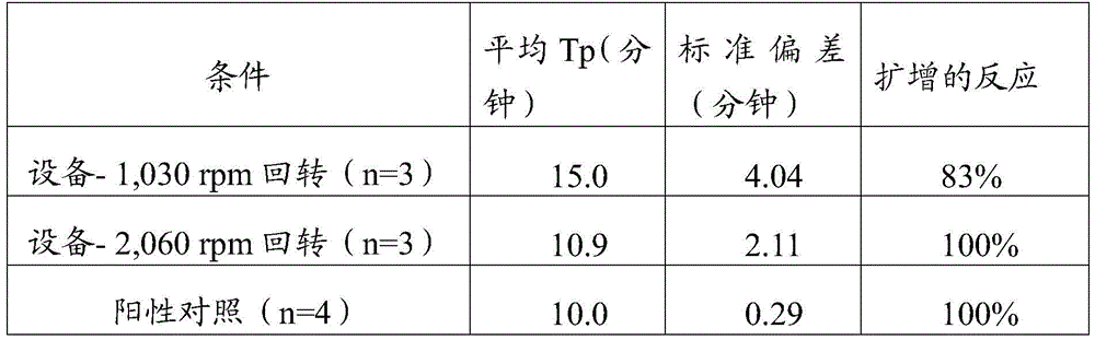
实施例2:交替改变的低速回转Example 2: Alternating low-speed slew
第二个实验以两个独立的部分进行,涉及使用1,030rpm的回转速度每15秒交替改变回转方向持续60秒。使用标准实验室台式方案将另外的干燥试剂再水合,用作阳性对照。这些再水合试剂被用于利用LAMP扩增核酸序列。阳性对照的性能被用作比较该设备再水合情况的结果的基准。The second experiment was performed in two separate sections and involved alternating rotation directions every 15 seconds for 60 seconds using a rotation speed of 1,030 rpm. Additional dry reagents were rehydrated using standard laboratory benchtop protocols and used as positive controls. These rehydration reagents are used to amplify nucleic acid sequences using LAMP. The performance of the positive control was used as a benchmark to compare the results of the rehydration of the device.
第二个实验的结果在下表2中描述。与实施例1中的1,030rpm的单向回转的结果相比,这些结果表明,每15秒交替改变回转方向改善了设备的再水合性能,并允许采用较低的回转速度。The results of the second experiment are described in Table 2 below. Compared to the results for the 1,030 rpm unidirectional swivel in Example 1, these results show that alternating the swivel direction every 15 seconds improves the rehydration performance of the device and allows the use of lower swivel speeds.
表2Table 2
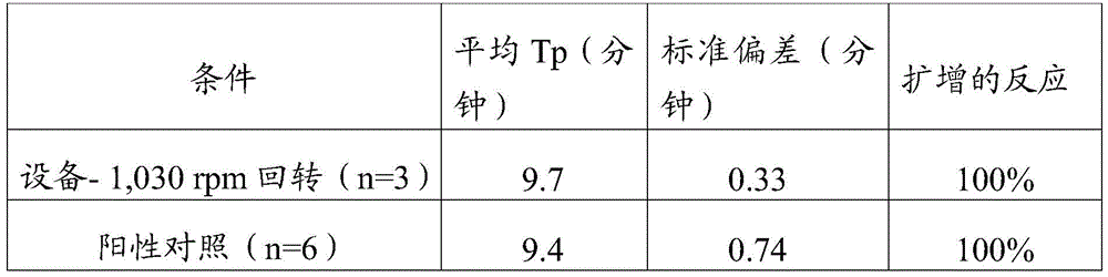
实施例3:交替改变的中速回转Example 3: Alternating medium-speed swings
第三个实验包括使用2,060rpm的回转速度每15秒交替改变回转方向,持续60秒。该方案的其余部分与第二个实验相同。The third experiment consisted of alternating rotation directions every 15 seconds for 60 seconds using a rotation speed of 2,060 rpm. The rest of the protocol was the same as the second experiment.
第三个实验的结果在下表3中描述。与实施例1中2,060rpm的单向回转的结果相比较,这些结果表明,甚至在2,060rpm下,每15秒交替改变回转方向通过降低再水合试剂的转正时间的标准偏差提高了设备的再水合性能。这些结果进一步表明,交替改变回转方向引起的增加的剪切力不会明显损害再水合的酶。The results of the third experiment are described in Table 3 below. Compared to the results of the 2,060 rpm one-way swivel in Example 1, these results show that even at 2,060 rpm, alternating the swivel direction every 15 seconds improves the rehydration of the device by reducing the standard deviation of the rehydration reagent's turn-up time. performance. These results further suggest that the increased shear force induced by alternating the direction of rotation does not significantly impair the rehydrating enzymes.
表3table 3
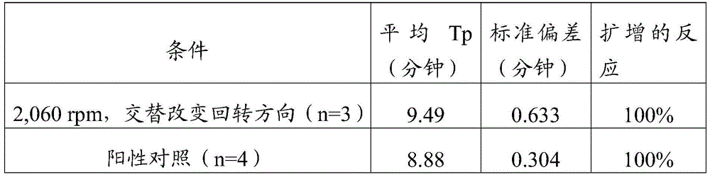
将通过设备利用2,060rpm交替改变的回转持续60秒来再水合干燥试剂的再水合程度与使用标准实验室台式方案再水合的对照进行比较。使用分光光度计对照标准曲线量化所得溶液的浓度。第四个实验的结果在下表4中描述。这些结果进一步表明,该设备能够匹配标准台式方案的再水合性能。The degree of rehydration by the device to rehydrate the dry reagents using alternating rotations at 2,060 rpm for 60 seconds was compared to a control rehydrated using a standard laboratory benchtop protocol. Use a spectrophotometer to quantify the concentration of the resulting solution against a standard curve. The results of the fourth experiment are described in Table 4 below. These results further demonstrate that the device is able to match the rehydration performance of standard benchtop protocols.
表4Table 4
实施例4:扩展的交替改变的回转Example 4: Extended Alternating Rotation
第四个实验包括以2,060rpm单向回转30秒和45秒,而不是之前三个实验所用的60秒持续时间。该方案的其余部分与实施例2和实施例3中描述的相同。The fourth experiment consisted of 30 seconds and 45 seconds of one-way slewing at 2,060 rpm instead of the 60 second duration used in the previous three experiments. The remainder of the protocol is the same as described in Example 2 and Example 3.
第四个实验的结果在下表5中描述。这些结果表明,该设备能够在不到60秒的时间内将干燥试剂再水合至可接受的程度。结合实施例2的结果,增加交替改变的回转方向有可能进一步加强这种能力。The results of the fourth experiment are described in Table 5 below. These results show that the device is able to rehydrate dry reagents to acceptable levels in less than 60 seconds. Combined with the results of Example 2, it is possible to further enhance this capability by adding alternating directions of rotation.
表5table 5
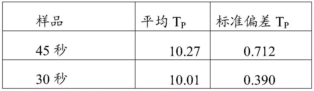

实施例5:没有核酸损失Example 5: No Nucleic Acid Loss
为了证实在如图1-图7所述的设备中没有核酸因混合而损失,将已知浓度的核酸靶在不存在干燥试剂的情况下装载到设备中以2,060rpm交替改变的回转持续60秒,和装载到设备中不回转放置60秒。通过RT-qPCR将所得的核酸溶液的浓度与原始输入溶液进行比较。To confirm that no nucleic acid was lost due to mixing in the device as described in Figures 1-7, known concentrations of nucleic acid targets were loaded into the device in the absence of dry reagents in alternating rotations at 2,060 rpm for 60 seconds , and loaded into the device without rotation for 60 seconds. The concentration of the resulting nucleic acid solution was compared to the original input solution by RT-qPCR.
第一个实验的结果在下面的表6中描述,其证明了无论是设备本身的表面还是回转混合珠的行为都不会导致可检测的核酸损失或损伤。The results of the first experiment, described in Table 6 below, demonstrate that neither the surface of the device itself nor the behavior of the gyratory mixing beads resulted in detectable loss or damage of nucleic acids.
表6Table 6
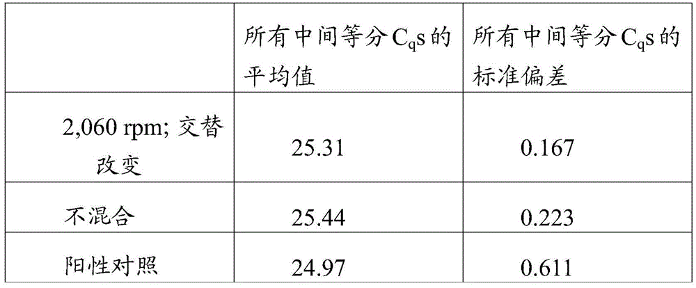
实施例6:热熔Example 6: Hot Melt
进行了一个实验来证明热熔该装置的有效性,如参考图2E和图2F所描述的。An experiment was performed to demonstrate the effectiveness of thermal fusion of the device, as described with reference to Figures 2E and 2F.
构建了测试试样,其由五个井孔(wells)组成,每个井孔连接到各自的气动隔室。井孔(包括从公共管线通向井孔的通路和从测定腔室通向空气腔室的气动导管)的体积分别为5.28mm3、7.56mm3、13.12mm3、5.32mm3和9.96mm3。空气腔室的体积分别为9.24mm3、13.22mm3、22.96mm3、9.29mm3和17.43mm3。以9.2psi至10psi的斜坡式压力(rampedpressure),将水填充到样品试样内。测定腔室被均匀填充,且填充过程本身没有造成明显气泡。在9.2psi下,所有的井孔都被基本上填充,并且在10psi下,井孔被完全填充,并且流体延伸到将井孔连接到空气腔室的气动导管中。因此,这两个压力之间的压力(例如9.6psi)被认为对于完全填充是理想的。A test coupon was constructed consisting of five wells, each connected to a respective pneumatic compartment. The volumes of the wellbore (including access from the common line to the wellbore and pneumatic conduit from the assay chamber to the air chamber) were 5.28mm 3 , 7.56mm 3 , 13.12mm 3 , 5.32mm 3 and 9.96mm 3 , respectively. The volumes of the air chambers were 9.24 mm 3 , 13.22 mm 3 , 22.96 mm 3 , 9.29 mm 3 and 17.43 mm 3 , respectively. Water was filled into the sample coupon at a ramped pressure of 9.2 psi to 10 psi. The assay chamber was filled uniformly and the filling process itself did not cause significant air bubbles. At 9.2 psi, all wells were substantially filled, and at 10 psi, the wells were fully filled and fluid extended into the pneumatic conduit connecting the wells to the air chamber. Therefore, a pressure between these two pressures (eg, 9.6 psi) is considered ideal for complete filling.
在热熔后,流控路径保持两侧的压力;空气和水(至10psig)。此外,流控路径在热熔后10天仍然保持压力(通过加压井孔的隆起和无液体泄漏观察到)。After heat fusion, the fluidic path maintains pressure on both sides; air and water (to 10 psig). In addition, the fluidic path remained under pressure 10 days after thermal fusion (observed by the bulge of the pressurized wellbore and the absence of liquid leakage).
实施例7:扩增和检测Example 7: Amplification and Detection
进行了一个实验来证明,在对参考图1-图7所述的流控路径进行热熔后,加热流控路径不会在样品腔室内引起明显的气泡形成。如实施例6所述,构建由五个井孔组成的测试试样。An experiment was performed to demonstrate that heating the fluidic path did not cause significant bubble formation within the sample chamber after thermal fusion of the fluidic path described with reference to Figures 1-7. A test coupon consisting of five wells was constructed as described in Example 6.
补充有MgCl2、dNTPs、LAMP引物、FAM分子信标探针、Bst 2聚合酶(新英格兰生物实验室(New England Biolabs))和RTx温启动(逆转录酶;新英格兰生物实验室)和100,000份CT 23S DNA(作为模板)的恒温扩增缓冲液(新英格兰生物实验室)被填充到样品试样,其中压力倾斜升至13psi。然后试样热熔并加热至64℃。在升高温度的最初几分钟期间,一些测定腔室中会形成非常小的气泡。在30分钟的过程中,这些微小的气泡是稳定的,并且不会干扰扩增或图像处理。在暴露于64℃的9-15分钟内,五个井孔中的每一个井孔内的扩增都是视觉可检测的。Supplemented with MgCl2 , dNTPs, LAMP primers, FAM molecular beacon probes, Bst2 polymerase (New England Biolabs) and RTx warm start (Reverse Transcriptase; New England Biolabs) and 100,000 Isothermal Amplification Buffer (New England Biolabs) of CT 23S DNA (as template) was filled into the sample coupon with the pressure ramped up to 13 psi. The sample was then melted and heated to 64°C. During the first few minutes of elevated temperature, very small bubbles formed in some assay chambers. These tiny bubbles were stable over the course of 30 minutes and did not interfere with amplification or image processing. Amplification in each of the five wells was visually detectable within 9-15 minutes of exposure to 64°C.
参考标记列表List of reference marks
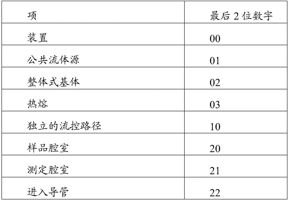


Claims (10)
Priority Applications (1)
| Application Number | Priority Date | Filing Date | Title |
|---|---|---|---|
| CN202210359309.4A CN114832873B (en) | 2018-03-22 | 2019-03-22 | Reaction wells for assay equipment |
Applications Claiming Priority (7)
| Application Number | Priority Date | Filing Date | Title |
|---|---|---|---|
| US15/928,551 | 2018-03-22 | ||
| US15/928,551 US10046322B1 (en) | 2018-03-22 | 2018-03-22 | Reaction well for assay device |
| US16/027,749 | 2018-07-05 | ||
| US16/027,749 US10618047B2 (en) | 2018-03-22 | 2018-07-05 | Reaction well for assay device |
| PCT/US2019/023702 WO2019183559A1 (en) | 2018-03-22 | 2019-03-22 | Reaction well for assay device |
| CN201980021278.8A CN112041068B (en) | 2018-03-22 | 2019-03-22 | Reaction wells for assay equipment |
| CN202210359309.4A CN114832873B (en) | 2018-03-22 | 2019-03-22 | Reaction wells for assay equipment |
Related Parent Applications (1)
| Application Number | Title | Priority Date | Filing Date |
|---|---|---|---|
| CN201980021278.8A Division CN112041068B (en) | 2018-03-22 | 2019-03-22 | Reaction wells for assay equipment |
Publications (2)
| Publication Number | Publication Date |
|---|---|
| CN114832873A true CN114832873A (en) | 2022-08-02 |
| CN114832873B CN114832873B (en) | 2024-04-30 |
Family
ID=63079344
Family Applications (4)
| Application Number | Title | Priority Date | Filing Date |
|---|---|---|---|
| CN201980021278.8A Active CN112041068B (en) | 2018-03-22 | 2019-03-22 | Reaction wells for assay equipment |
| CN201980021309.XA Active CN112055617B (en) | 2018-03-22 | 2019-03-22 | Optically responsive well for assay devices |
| CN202310060870.7A Pending CN116037234A (en) | 2018-03-22 | 2019-03-22 | Optical Reaction Wells for Assay Devices |
| CN202210359309.4A Active CN114832873B (en) | 2018-03-22 | 2019-03-22 | Reaction wells for assay equipment |
Family Applications Before (3)
| Application Number | Title | Priority Date | Filing Date |
|---|---|---|---|
| CN201980021278.8A Active CN112041068B (en) | 2018-03-22 | 2019-03-22 | Reaction wells for assay equipment |
| CN201980021309.XA Active CN112055617B (en) | 2018-03-22 | 2019-03-22 | Optically responsive well for assay devices |
| CN202310060870.7A Pending CN116037234A (en) | 2018-03-22 | 2019-03-22 | Optical Reaction Wells for Assay Devices |
Country Status (11)
| Country | Link |
|---|---|
| US (4) | US10046322B1 (en) |
| EP (2) | EP3768428A4 (en) |
| JP (2) | JP7401448B2 (en) |
| KR (1) | KR20200139697A (en) |
| CN (4) | CN112041068B (en) |
| AU (2) | AU2019237517B2 (en) |
| CA (1) | CA3092112A1 (en) |
| IL (2) | IL311285A (en) |
| SG (1) | SG11202007766VA (en) |
| WO (2) | WO2019183559A1 (en) |
| ZA (2) | ZA202005052B (en) |
Families Citing this family (9)
| Publication number | Priority date | Publication date | Assignee | Title |
|---|---|---|---|---|
| US10046322B1 (en) | 2018-03-22 | 2018-08-14 | Talis Biomedical Corporation | Reaction well for assay device |
| US11008627B2 (en) | 2019-08-15 | 2021-05-18 | Talis Biomedical Corporation | Diagnostic system |
| EP3992610A1 (en) * | 2020-10-30 | 2022-05-04 | Hach Lange GmbH | A process photometer arrangement |
| CN113897283A (en) * | 2021-05-18 | 2022-01-07 | 成都万众壹芯生物科技有限公司 | Microfluidic nucleic acid detection kit and detection device |
| CN113522381B (en) * | 2021-05-26 | 2022-11-15 | 西北工业大学太仓长三角研究院 | Different concentration liquid drop produces chip based on induction charge electroosmosis |
| KR102704928B1 (en) * | 2021-08-25 | 2024-09-10 | 한국기계연구원 | Microfluidic device being capable of initiating flow sequentially from multiple reservoirs |
| DE102022210777A1 (en) | 2022-10-13 | 2024-04-18 | Robert Bosch Gesellschaft mit beschränkter Haftung | Microfluidic cartridge, microfluidic device and method for its operation |
| WO2024137514A1 (en) | 2022-12-22 | 2024-06-27 | Synthego Corporation | Systems and method for automated oligonucleotide synthesis |
| USD1069156S1 (en) | 2023-04-10 | 2025-04-01 | Becton, Dickinson And Company | Dispensing device |
Citations (12)
| Publication number | Priority date | Publication date | Assignee | Title |
|---|---|---|---|---|
| US4070249A (en) * | 1976-06-08 | 1978-01-24 | American Home Products Corporation | Apparatus for compensating for pressure within a biological test device |
| WO1998040466A1 (en) * | 1997-03-13 | 1998-09-17 | Corning Incorporated | Integrated fluid circuit for the execution of a chemical or biological process |
| CN102112594A (en) * | 2008-08-01 | 2011-06-29 | 智能生物系统公司 | A sample port of a cell culture system |
| EP2436446A1 (en) * | 2010-10-04 | 2012-04-04 | F. Hoffmann-La Roche AG | Multi-chamber plate and method for filling it with a sample fluid |
| CN102655938A (en) * | 2009-11-02 | 2012-09-05 | 环境,食品及农村国务部,由动物卫生和兽医实验所代理 | Device and apparatus |
| CN102802402A (en) * | 2009-05-29 | 2012-11-28 | 生命技术公司 | Fluidic systems for sequential delivery of reagents |
| US20140272982A1 (en) * | 2013-03-14 | 2014-09-18 | Formulatrix, Inc. | Microfluidic device |
| CN104582849A (en) * | 2012-05-09 | 2015-04-29 | 统计诊断与创新有限公司 | Multiple reaction chambers in a test cartridge |
| CN105121019A (en) * | 2013-03-15 | 2015-12-02 | 伊鲁米那股份有限公司 | System and method for generating or analyzing a biological sample |
| CN105344394A (en) * | 2015-09-24 | 2016-02-24 | 基蛋生物科技股份有限公司 | High-precision micro liquid equivalent flow distributor |
| US20170014821A1 (en) * | 2015-07-17 | 2017-01-19 | Stat-Diagnostica & Innovation, S.L. | Fluidic System for Performing Assays |
| CN107206407A (en) * | 2015-01-07 | 2017-09-26 | 诺信公司 | Fuid distribution system |
Family Cites Families (123)
| Publication number | Priority date | Publication date | Assignee | Title |
|---|---|---|---|---|
| US3454178A (en) | 1966-01-10 | 1969-07-08 | Charles E Bender | Sterile cap for a freeze-drying container and method of freeze-drying materials under sterile conditions |
| US3689224A (en) | 1966-04-13 | 1972-09-05 | Westinghouse Electric Corp | Chemical contaminant detection sampler |
| US4119407A (en) | 1976-03-08 | 1978-10-10 | Bio-Dynamics, Inc. | Cuvette with reagent release means |
| US4426451A (en) * | 1981-01-28 | 1984-01-17 | Eastman Kodak Company | Multi-zoned reaction vessel having pressure-actuatable control means between zones |
| US4608231A (en) | 1984-12-12 | 1986-08-26 | Becton, Dickinson And Company | Self-contained reagent package device for an assay |
| US4964539A (en) | 1989-04-06 | 1990-10-23 | Seaquist Closures | Multiple chamber dispensing container and closure system |
| EP0501796A3 (en) | 1991-03-01 | 1993-10-06 | Biotrack, Inc. | Capillary stop-flow junction having improved stability against accidental fluid flow |
| US5256571A (en) | 1991-05-01 | 1993-10-26 | Cytyc Corporation | Cell preservative solution |
| JPH10503993A (en) | 1994-08-19 | 1998-04-14 | ダブリュ.エル.ゴア アンド アソシエイツ,インコーポレイティド | Vented vials for lyophilization and methods to minimize contamination of lyophilized products |
| US5856174A (en) * | 1995-06-29 | 1999-01-05 | Affymetrix, Inc. | Integrated nucleic acid diagnostic device |
| US5662866A (en) | 1995-09-25 | 1997-09-02 | Steris Corporation | Two compartment cup for powdered sterilant reagent components |
| US6027694A (en) | 1996-10-17 | 2000-02-22 | Texperts, Inc. | Spillproof microplate assembly |
| JP2001521162A (en) | 1997-10-27 | 2001-11-06 | アイデックス・ラボラトリーズ・インコーポレーテッド | Analysis apparatus and method for identifying analyte in solution |
| US6043097A (en) | 1997-12-05 | 2000-03-28 | Bayer Corporation | Reagent package |
| US6204375B1 (en) | 1998-07-31 | 2001-03-20 | Ambion, Inc. | Methods and reagents for preserving RNA in cell and tissue samples |
| US6087182A (en) * | 1998-08-27 | 2000-07-11 | Abbott Laboratories | Reagentless analysis of biological samples |
| US6637463B1 (en) | 1998-10-13 | 2003-10-28 | Biomicro Systems, Inc. | Multi-channel microfluidic system design with balanced fluid flow distribution |
| EP1153303B1 (en) | 1999-02-16 | 2006-09-27 | Applera Corporation | Bead dispensing system |
| US7195670B2 (en) | 2000-06-27 | 2007-03-27 | California Institute Of Technology | High throughput screening of crystallization of materials |
| GB9922971D0 (en) | 1999-09-29 | 1999-12-01 | Secr Defence | Reaction system |
| US6734401B2 (en) * | 2000-06-28 | 2004-05-11 | 3M Innovative Properties Company | Enhanced sample processing devices, systems and methods |
| US6627159B1 (en) | 2000-06-28 | 2003-09-30 | 3M Innovative Properties Company | Centrifugal filling of sample processing devices |
| EP1314024A4 (en) | 2000-08-02 | 2007-04-11 | Caliper Life Sciences Inc | High throughput separations based analysis systems |
| US6615856B2 (en) | 2000-08-04 | 2003-09-09 | Biomicro Systems, Inc. | Remote valving for microfluidic flow control |
| JP2002100291A (en) | 2000-09-21 | 2002-04-05 | Hitachi Ltd | Method and apparatus for measuring electron beam intensity distribution of color cathode ray tube and method of manufacturing color cathode ray tube |
| US6453928B1 (en) | 2001-01-08 | 2002-09-24 | Nanolab Ltd. | Apparatus, and method for propelling fluids |
| WO2002060585A1 (en) | 2001-01-25 | 2002-08-08 | Senomyx, Inc. | Method and apparatus for solid or solution phase reaction under ambient or inert conditions |
| US6805841B2 (en) | 2001-05-09 | 2004-10-19 | The Provost Fellows And Scholars Of The College Of The Holy And Undivided Trinity Of Queen Elizabeth Near Dublin | Liquid pumping system |
| US20040208751A1 (en) | 2001-05-22 | 2004-10-21 | Lazar Juliana M | Microchip integrated multi-channel electroosmotic pumping system |
| US7179423B2 (en) | 2001-06-20 | 2007-02-20 | Cytonome, Inc. | Microfluidic system including a virtual wall fluid interface port for interfacing fluids with the microfluidic system |
| GB0129816D0 (en) | 2001-12-13 | 2002-01-30 | The Technology Partnership Plc | Testing device for chemical or biochemical analysis |
| DE20121042U1 (en) * | 2001-12-29 | 2002-07-18 | Bolte, Georg, Dr., 33790 Halle | Device for testing the wettability of surfaces |
| JP3569267B2 (en) * | 2002-03-27 | 2004-09-22 | コニカミノルタホールディングス株式会社 | Fluid transport system |
| EP1542010A4 (en) | 2002-07-12 | 2007-11-21 | Mitsubishi Chem Corp | ANALYSIS CHIP, ANALYTICAL CHIP UNIT, ANALYSIS APPARATUS, ANALYSIS METHOD WITH THE APPARATUS AND METHOD FOR PRODUCING THE ANALYSIS CHIP |
| US7135147B2 (en) | 2002-07-26 | 2006-11-14 | Applera Corporation | Closing blade for deformable valve in a microfluidic device and method |
| JP3768486B2 (en) | 2003-03-20 | 2006-04-19 | 株式会社エンプラス | Micro fluid handling equipment |
| US6843281B1 (en) | 2003-07-30 | 2005-01-18 | Agilent Techinologies, Inc. | Methods and apparatus for introducing liquids into microfluidic chambers |
| US20050086830A1 (en) | 2003-10-24 | 2005-04-28 | Zukor Kenneth S. | Processing cap assembly for isolating contents of a container |
| CN100562745C (en) * | 2003-12-23 | 2009-11-25 | 卡钳生命科学股份有限公司 | Analyte injection system |
| US7407799B2 (en) * | 2004-01-16 | 2008-08-05 | California Institute Of Technology | Microfluidic chemostat |
| US7432106B2 (en) | 2004-03-24 | 2008-10-07 | Applied Biosystems Inc. | Liquid processing device including gas trap, and system and method |
| US20060099567A1 (en) | 2004-04-08 | 2006-05-11 | Biomatrica, Inc. | Integration of sample storage and sample management for life science |
| US20080176209A1 (en) | 2004-04-08 | 2008-07-24 | Biomatrica, Inc. | Integration of sample storage and sample management for life science |
| CA2560513A1 (en) | 2004-04-08 | 2005-12-01 | Biomatrica, Inc. | Integration of sample storage and sample management for life science |
| US8961900B2 (en) | 2004-04-28 | 2015-02-24 | Yokogawa Electric Corporation | Chemical reaction cartridge, method of producing chemical reaction cartridge, and mechanism for driving chemical reaction cartridge |
| US7887750B2 (en) | 2004-05-05 | 2011-02-15 | Bayer Healthcare Llc | Analytical systems, devices, and cartridges therefor |
| US7645423B2 (en) | 2004-08-20 | 2010-01-12 | International Business Machines Corporation | Optical micro plugs for multichannel and multilayer pharmaceutical device |
| EP1828746B1 (en) | 2004-10-18 | 2016-12-28 | Life Technologies Corporation | Fluid processing device including composite material flow modulator |
| GB0503986D0 (en) | 2005-02-26 | 2005-04-06 | Secr Defence | Reaction apparatus |
| US7731907B2 (en) * | 2005-04-09 | 2010-06-08 | Boehringer Ingelheim Microparts Gmbh | Device and process for testing a sample liquid |
| WO2006116616A2 (en) | 2005-04-26 | 2006-11-02 | Applera Corporation | Systems and methods for multiple analyte detection |
| US20060286004A1 (en) | 2005-06-15 | 2006-12-21 | Jacobs Merrit N | Containers for reducing or eliminating foaming |
| US7763453B2 (en) | 2005-11-30 | 2010-07-27 | Micronics, Inc. | Microfluidic mixing and analytic apparatus |
| US20080241910A1 (en) | 2007-03-27 | 2008-10-02 | Searete Llc, A Limited Liability Corporation Of The State Of Delaware | Devices for pathogen detection |
| US9056291B2 (en) | 2005-11-30 | 2015-06-16 | Micronics, Inc. | Microfluidic reactor system |
| US7998708B2 (en) * | 2006-03-24 | 2011-08-16 | Handylab, Inc. | Microfluidic system for amplifying and detecting polynucleotides in parallel |
| US20070280857A1 (en) | 2006-06-02 | 2007-12-06 | Applera Corporation | Devices and Methods for Positioning Dried Reagent In Microfluidic Devices |
| US20070280856A1 (en) | 2006-06-02 | 2007-12-06 | Applera Corporation | Devices and Methods for Controlling Bubble Formation in Microfluidic Devices |
| US8187557B2 (en) | 2006-07-13 | 2012-05-29 | Cepheid | Reagent reservoir system for analytical instruments |
| EP1878802A1 (en) * | 2006-07-14 | 2008-01-16 | Roche Diagnostics GmbH | Disposable device for analysing a liquid sample containing a nucleic acid with a nucleic acid amplification apparatus |
| WO2008024319A2 (en) | 2006-08-20 | 2008-02-28 | Codon Devices, Inc. | Microfluidic devices for nucleic acid assembly |
| KR100758274B1 (en) | 2006-09-27 | 2007-09-12 | 한국전자통신연구원 | A microfluidic device for equalizing the flow of multiple microfluids in the chamber, and a microfluidic network using the same |
| CN103497991A (en) * | 2006-11-06 | 2014-01-08 | 科隆迪亚戈有限公司 | Device and method for analysis using binding members |
| WO2008127438A2 (en) | 2006-11-27 | 2008-10-23 | The Penn State Research Foundation | Parallel flow control (pfc) approach for active control, characterization, and manipulation of nanofluidics |
| EP3032251B1 (en) | 2007-04-04 | 2018-05-23 | Ande Corporation | Plastic microfluidic separation and detection platforms |
| CN101688170A (en) | 2007-04-24 | 2010-03-31 | 生物马特里卡公司 | Sample storage for life science |
| KR101335726B1 (en) | 2007-06-04 | 2013-12-04 | 삼성전자주식회사 | Disk type microfluidic device for conducting immunoassey and biochemistry analysis simultaneously |
| US20090047191A1 (en) | 2007-06-08 | 2009-02-19 | Gafur Zainiev | Closed space disposable micro-reactor and uses thereof |
| CN103157400B (en) * | 2007-06-21 | 2014-12-24 | 简·探针公司 | Instrument and method for exposing container to multiple areas |
| US20090136385A1 (en) | 2007-07-13 | 2009-05-28 | Handylab, Inc. | Reagent Tube |
| US8105783B2 (en) | 2007-07-13 | 2012-01-31 | Handylab, Inc. | Microfluidic cartridge |
| WO2009035847A1 (en) | 2007-09-14 | 2009-03-19 | Siemens Heathcare Diagnostics Inc. | Apparatus and methods for encapsulation of in vitro diagnostic reagents |
| US20090081768A1 (en) | 2007-09-21 | 2009-03-26 | Applera Corporation | Devices and Methods for Thermally Isolating Chambers of an Assay Card |
| DE102007059533A1 (en) | 2007-12-06 | 2009-06-10 | Thinxxs Microtechnology Ag | Microfluidic storage device |
| WO2009078107A1 (en) | 2007-12-19 | 2009-06-25 | Shimadzu Corporation | Dispensing device |
| CA2715985A1 (en) * | 2008-02-21 | 2009-08-27 | Avantra Biosciences Corporation | Assays based on liquid flow over arrays |
| US20110041922A1 (en) | 2008-03-12 | 2011-02-24 | Fluimedix Aps | Controlled liquid handling |
| JP5244461B2 (en) | 2008-05-29 | 2013-07-24 | 株式会社東芝 | Chemical analyzer and analysis chip |
| EP2300164B1 (en) | 2008-06-19 | 2018-03-14 | Boehringer Ingelheim Microparts GmbH | Fluid metering container |
| KR101578149B1 (en) | 2009-01-29 | 2015-12-17 | 삼성전자주식회사 | Valve unit for microfluid control and manufacturing method thereof |
| DE102009015395B4 (en) | 2009-03-23 | 2022-11-24 | Thinxxs Microtechnology Gmbh | Flow cell for treating and/or examining a fluid |
| EP2430195B1 (en) | 2009-05-11 | 2019-01-23 | Biomatrica, INC. | Compositions and methods for biological sample storage |
| KR20110027419A (en) | 2009-09-10 | 2011-03-16 | 삼성전자주식회사 | Fluid receiving chamber, microfluidic device with fluid receiving chamber, and fluid mixing method |
| SG169918A1 (en) | 2009-10-02 | 2011-04-29 | Fluidigm Corp | Microfluidic devices with removable cover and methods of fabrication and application |
| DE102009048378B3 (en) | 2009-10-06 | 2011-02-17 | INSTITUT FüR MIKROTECHNIK MAINZ GMBH | Microfluidic structure |
| CA3028780C (en) | 2009-12-07 | 2022-05-31 | Meso Scale Technologies, Llc | Assay cartridges and methods of using the same |
| KR101851117B1 (en) * | 2010-01-29 | 2018-04-23 | 마이크로닉스 인코포레이티드. | Sample-to-answer microfluidic cartridge |
| ES2914111T3 (en) | 2010-03-01 | 2022-06-07 | Ecole Polytechnique Fed Lausanne Epfl | Apparatus and method for detecting and measuring biomolecular interactions |
| US8720036B2 (en) | 2010-03-09 | 2014-05-13 | Netbio, Inc. | Unitary biochip providing sample-in to results-out processing and methods of manufacture |
| WO2011126892A2 (en) | 2010-03-30 | 2011-10-13 | Advanced Liquid Logic, Inc. | Droplet operations platform |
| CA3016653C (en) * | 2010-04-16 | 2024-01-02 | Opko Diagnostics, Llc | Feedback control in microfluidic systems |
| US20130109106A1 (en) * | 2010-07-09 | 2013-05-02 | Koninklijke Philips Electronics N.V. | System for selectively proceeding a sample |
| US9376709B2 (en) | 2010-07-26 | 2016-06-28 | Biomatrica, Inc. | Compositions for stabilizing DNA and RNA in blood and other biological samples during shipping and storage at ambient temperatures |
| GB201013267D0 (en) | 2010-08-06 | 2010-09-22 | Enigma Diagnostics Ltd | Vessel and process for production thereof |
| EP2624954B1 (en) | 2010-10-07 | 2020-08-26 | BOEHRINGER INGELHEIM microParts GmbH | Method for washing a microfluid cavity |
| GB201101488D0 (en) | 2011-01-28 | 2011-03-16 | Ge Healthcare Ltd | Container storing freeze dried biological sample |
| DE102011003856B4 (en) | 2011-02-09 | 2020-06-18 | Robert Bosch Gmbh | Microsystem for fluidic applications as well as manufacturing and use methods for a microsystem for fluidic applications |
| GB201103917D0 (en) | 2011-03-08 | 2011-04-20 | Univ Leiden | Apparatus for and methods of processing liquids or liquid based substances |
| WO2013106458A2 (en) | 2012-01-09 | 2013-07-18 | Micronics, Inc. | Microfluidic reactor system |
| JP6196661B2 (en) | 2012-04-20 | 2017-09-13 | スリップチップ, エルエルシー | Fluidic devices and systems for sample preparation or autonomous analysis |
| WO2013171483A1 (en) | 2012-05-18 | 2013-11-21 | Fluorogenics Ltd | Vessel of thermally conductive plastic for freeze - drying |
| EP2679307B1 (en) | 2012-06-28 | 2015-08-12 | Thinxxs Microtechnology Ag | Microstorage device, in particular for integration into a microfluid flow cell |
| ITTO20120703A1 (en) | 2012-08-03 | 2014-02-04 | Biomerieux Sa | DISPOSABLE MICROFLUID DEVICE, CARTRIDGE INCLUDING THE MICROFLUID DEVICE, APPARATUS TO PERFORM AN AMPLIFICATION OF NUCLEIC ACID, METHOD OF MANUFACTURING THE MICROFLUIDIC DEVICE, AND METHOD OF USING THE MICROFLUIDIC DEVICE |
| CN103849548A (en) | 2012-12-03 | 2014-06-11 | 三星电子株式会社 | Reagent container for amplifying nucleic acid, method of preparing the reagent container, method of storing the reagent, and microfluidic system for nucleic acid analysis |
| CA2903382A1 (en) | 2013-03-01 | 2014-09-12 | Wave 80 Biosciences, Inc. | Methods and systems for enhanced microfluidic processing |
| DE102013205412A1 (en) | 2013-03-27 | 2014-10-02 | Robert Bosch Gmbh | Normally closed valve for microfluidic components made of a polymer layer system and method |
| US9968930B2 (en) | 2013-04-04 | 2018-05-15 | Surnetics, Llc | Microfluidic products with controlled fluid flow |
| EP3300751B1 (en) | 2013-05-23 | 2022-07-06 | NewIV Medical Corp. | Pneumatically coupled direct drive fluid control system and process |
| DK2821138T4 (en) | 2013-07-05 | 2022-05-16 | Thinxxs Microtechnology Gmbh | FLOATING CELL WITH INTEGRATED DRY MATERIAL |
| US10946376B2 (en) | 2013-07-05 | 2021-03-16 | Thinxxs Microtechnology Ag | Carrier element for introducing a dry substance into a flow cell |
| SG11201602457RA (en) | 2013-09-30 | 2016-04-28 | Agency Science Tech & Res | Microfluidic device |
| US10191071B2 (en) * | 2013-11-18 | 2019-01-29 | IntegenX, Inc. | Cartridges and instruments for sample analysis |
| CA2931711C (en) | 2013-11-27 | 2019-06-25 | F.Hoffmann-La Roche Ag | A method for laser welding a disposable test-unit |
| DE102013114634A1 (en) | 2013-12-20 | 2015-06-25 | Karlsruher Institut für Technologie | Microfluidic bioreactor with a modular structure for the synthesis of cell metabolites, the method of use and its use |
| WO2016051272A1 (en) | 2014-09-29 | 2016-04-07 | Chipcare Corporation | A device for optical detection of cells comprising a cartridge and fluidic chip and methods thereof |
| EP3248018B1 (en) | 2015-01-22 | 2020-01-08 | Becton, Dickinson and Company | Devices and systems for molecular barcoding of nucleic acid targets in single cells |
| TWI581862B (en) | 2015-06-16 | 2017-05-11 | 亞諾法生技股份有限公司 | Holding carrier for a microfluidic device |
| US10233491B2 (en) * | 2015-06-19 | 2019-03-19 | IntegenX, Inc. | Valved cartridge and system |
| CN205047979U (en) * | 2015-09-30 | 2016-02-24 | 博奥生物集团有限公司 | Micro -fluidic valve and micro -fluidic chip |
| US11214823B2 (en) * | 2015-12-22 | 2022-01-04 | Canon U.S.A., Inc. | Sample-to-answer system for microorganism detection featuring target enrichment, amplification and detection |
| EP3263215B1 (en) | 2016-06-30 | 2021-04-28 | ThinXXS Microtechnology AG | Device with a flow cell with reagent storage |
| US20210008559A1 (en) | 2016-12-12 | 2021-01-14 | Talis Biomedical Corporation | Capsule containment of dried reagents |
| US10046322B1 (en) | 2018-03-22 | 2018-08-14 | Talis Biomedical Corporation | Reaction well for assay device |
-
2018
- 2018-03-22 US US15/928,551 patent/US10046322B1/en active Active
- 2018-07-05 US US16/027,749 patent/US10618047B2/en active Active
-
2019
- 2019-03-22 EP EP19771251.6A patent/EP3768428A4/en active Pending
- 2019-03-22 CN CN201980021278.8A patent/CN112041068B/en active Active
- 2019-03-22 SG SG11202007766VA patent/SG11202007766VA/en unknown
- 2019-03-22 EP EP19770621.1A patent/EP3768426A4/en active Pending
- 2019-03-22 IL IL311285A patent/IL311285A/en unknown
- 2019-03-22 CA CA3092112A patent/CA3092112A1/en active Pending
- 2019-03-22 KR KR1020207029194A patent/KR20200139697A/en active Pending
- 2019-03-22 IL IL276747A patent/IL276747B2/en unknown
- 2019-03-22 US US17/040,064 patent/US11633736B2/en active Active
- 2019-03-22 AU AU2019237517A patent/AU2019237517B2/en active Active
- 2019-03-22 WO PCT/US2019/023702 patent/WO2019183559A1/en not_active Ceased
- 2019-03-22 WO PCT/US2019/023764 patent/WO2019183608A1/en not_active Ceased
- 2019-03-22 CN CN201980021309.XA patent/CN112055617B/en active Active
- 2019-03-22 CN CN202310060870.7A patent/CN116037234A/en active Pending
- 2019-03-22 CN CN202210359309.4A patent/CN114832873B/en active Active
- 2019-03-22 JP JP2020550666A patent/JP7401448B2/en active Active
-
2020
- 2020-08-14 ZA ZA2020/05052A patent/ZA202005052B/en unknown
-
2023
- 2023-03-09 US US18/181,493 patent/US20240001364A1/en not_active Abandoned
- 2023-09-13 ZA ZA2023/08720A patent/ZA202308720B/en unknown
- 2023-12-07 JP JP2023206579A patent/JP2024026300A/en active Pending
-
2024
- 2024-02-22 AU AU2024201167A patent/AU2024201167A1/en active Pending
Patent Citations (13)
| Publication number | Priority date | Publication date | Assignee | Title |
|---|---|---|---|---|
| US4070249A (en) * | 1976-06-08 | 1978-01-24 | American Home Products Corporation | Apparatus for compensating for pressure within a biological test device |
| WO1998040466A1 (en) * | 1997-03-13 | 1998-09-17 | Corning Incorporated | Integrated fluid circuit for the execution of a chemical or biological process |
| CN102112594A (en) * | 2008-08-01 | 2011-06-29 | 智能生物系统公司 | A sample port of a cell culture system |
| CN102802402A (en) * | 2009-05-29 | 2012-11-28 | 生命技术公司 | Fluidic systems for sequential delivery of reagents |
| CN102655938A (en) * | 2009-11-02 | 2012-09-05 | 环境,食品及农村国务部,由动物卫生和兽医实验所代理 | Device and apparatus |
| US20120270225A1 (en) * | 2009-11-02 | 2012-10-25 | The Secretary of State for Environment, Food & Rural Affairs Acting Through the Animal Health and | Device and apparatus |
| EP2436446A1 (en) * | 2010-10-04 | 2012-04-04 | F. Hoffmann-La Roche AG | Multi-chamber plate and method for filling it with a sample fluid |
| CN104582849A (en) * | 2012-05-09 | 2015-04-29 | 统计诊断与创新有限公司 | Multiple reaction chambers in a test cartridge |
| US20140272982A1 (en) * | 2013-03-14 | 2014-09-18 | Formulatrix, Inc. | Microfluidic device |
| CN105121019A (en) * | 2013-03-15 | 2015-12-02 | 伊鲁米那股份有限公司 | System and method for generating or analyzing a biological sample |
| CN107206407A (en) * | 2015-01-07 | 2017-09-26 | 诺信公司 | Fuid distribution system |
| US20170014821A1 (en) * | 2015-07-17 | 2017-01-19 | Stat-Diagnostica & Innovation, S.L. | Fluidic System for Performing Assays |
| CN105344394A (en) * | 2015-09-24 | 2016-02-24 | 基蛋生物科技股份有限公司 | High-precision micro liquid equivalent flow distributor |
Also Published As
Similar Documents
| Publication | Publication Date | Title |
|---|---|---|
| CN114832873B (en) | Reaction wells for assay equipment | |
| Li et al. | A “place n play” modular pump for portable microfluidic applications | |
| JP4888394B2 (en) | Microreactor and liquid feeding method using the same | |
| US7919306B2 (en) | Biological sample reaction chip, biological sample reaction apparatus, and biological sample reaction method | |
| US11478791B2 (en) | Flow control and processing cartridge | |
| CN115305183A (en) | Centrifugal microfluidic chip integrating isothermal amplification and CRISPR/Cas nucleic acid detection and method | |
| WO2006099042A2 (en) | Microfluidic valve for liquids | |
| US20170234783A1 (en) | Biological substance extraction device and biological substance extraction apparatus | |
| HK40079357A (en) | Reaction well for assay device | |
| HK40079357B (en) | Reaction well for assay device | |
| HK40032242A (en) | Reaction well for assay device | |
| HK40032242B (en) | Reaction well for assay device | |
| US10537862B2 (en) | Valve-less mixing method and mixing device | |
| HK40091186A (en) | Optical reaction well for assay device | |
| KR20250023506A (en) | SYSTEMS AND METHODS FOR PERFORMING BIOLOGICAL ASSAYS USING A THERMALLY SEALED VALVE | |
| HK40034346B (en) | Optical reaction well for assay device | |
| CN119614557B (en) | A method for processing nucleic acid | |
| CN114875121B (en) | Apparatus and method for detecting nucleic acid amplification products using lateral chromatography test strips | |
| Kinahan et al. | Nucleic acid purification on a Lab-on-a-Disc with time-controlled incubation | |
| EP3313559A1 (en) | Valve-less mixing method and mixing device |
Legal Events
| Date | Code | Title | Description |
|---|---|---|---|
| PB01 | Publication | ||
| PB01 | Publication | ||
| SE01 | Entry into force of request for substantive examination | ||
| SE01 | Entry into force of request for substantive examination | ||
| REG | Reference to a national code |
Ref country code: HK Ref legal event code: DE Ref document number: 40079357 Country of ref document: HK |
|
| GR01 | Patent grant | ||
| GR01 | Patent grant |