CN100562745C - Analyte injection system - Google Patents
Analyte injection system Download PDFInfo
- Publication number
- CN100562745C CN100562745C CNB2004800326937A CN200480032693A CN100562745C CN 100562745 C CN100562745 C CN 100562745C CN B2004800326937 A CNB2004800326937 A CN B2004800326937A CN 200480032693 A CN200480032693 A CN 200480032693A CN 100562745 C CN100562745 C CN 100562745C
- Authority
- CN
- China
- Prior art keywords
- channel
- acid
- analyte
- sample
- electrolyte
- Prior art date
- Legal status (The legal status is an assumption and is not a legal conclusion. Google has not performed a legal analysis and makes no representation as to the accuracy of the status listed.)
- Expired - Lifetime
Links
- 0 CC*C(CC)[C@@](C)(C(C)CC)[C@@](CN)N* Chemical compound CC*C(CC)[C@@](C)(C(C)CC)[C@@](CN)N* 0.000 description 1
Images


Classifications
-
- B—PERFORMING OPERATIONS; TRANSPORTING
- B01—PHYSICAL OR CHEMICAL PROCESSES OR APPARATUS IN GENERAL
- B01L—CHEMICAL OR PHYSICAL LABORATORY APPARATUS FOR GENERAL USE
- B01L3/00—Containers or dishes for laboratory use, e.g. laboratory glassware; Droppers
- B01L3/50—Containers for the purpose of retaining a material to be analysed, e.g. test tubes
- B01L3/502—Containers for the purpose of retaining a material to be analysed, e.g. test tubes with fluid transport, e.g. in multi-compartment structures
- B01L3/5027—Containers for the purpose of retaining a material to be analysed, e.g. test tubes with fluid transport, e.g. in multi-compartment structures by integrated microfluidic structures, i.e. dimensions of channels and chambers are such that surface tension forces are important, e.g. lab-on-a-chip
- B01L3/502715—Containers for the purpose of retaining a material to be analysed, e.g. test tubes with fluid transport, e.g. in multi-compartment structures by integrated microfluidic structures, i.e. dimensions of channels and chambers are such that surface tension forces are important, e.g. lab-on-a-chip characterised by interfacing components, e.g. fluidic, electrical, optical or mechanical interfaces
-
- B—PERFORMING OPERATIONS; TRANSPORTING
- B01—PHYSICAL OR CHEMICAL PROCESSES OR APPARATUS IN GENERAL
- B01L—CHEMICAL OR PHYSICAL LABORATORY APPARATUS FOR GENERAL USE
- B01L3/00—Containers or dishes for laboratory use, e.g. laboratory glassware; Droppers
- B01L3/50—Containers for the purpose of retaining a material to be analysed, e.g. test tubes
- B01L3/502—Containers for the purpose of retaining a material to be analysed, e.g. test tubes with fluid transport, e.g. in multi-compartment structures
- B01L3/5027—Containers for the purpose of retaining a material to be analysed, e.g. test tubes with fluid transport, e.g. in multi-compartment structures by integrated microfluidic structures, i.e. dimensions of channels and chambers are such that surface tension forces are important, e.g. lab-on-a-chip
- B01L3/502746—Containers for the purpose of retaining a material to be analysed, e.g. test tubes with fluid transport, e.g. in multi-compartment structures by integrated microfluidic structures, i.e. dimensions of channels and chambers are such that surface tension forces are important, e.g. lab-on-a-chip characterised by the means for controlling flow resistance, e.g. flow controllers, baffles
-
- B—PERFORMING OPERATIONS; TRANSPORTING
- B01—PHYSICAL OR CHEMICAL PROCESSES OR APPARATUS IN GENERAL
- B01L—CHEMICAL OR PHYSICAL LABORATORY APPARATUS FOR GENERAL USE
- B01L3/00—Containers or dishes for laboratory use, e.g. laboratory glassware; Droppers
- B01L3/50—Containers for the purpose of retaining a material to be analysed, e.g. test tubes
- B01L3/502—Containers for the purpose of retaining a material to be analysed, e.g. test tubes with fluid transport, e.g. in multi-compartment structures
- B01L3/5027—Containers for the purpose of retaining a material to be analysed, e.g. test tubes with fluid transport, e.g. in multi-compartment structures by integrated microfluidic structures, i.e. dimensions of channels and chambers are such that surface tension forces are important, e.g. lab-on-a-chip
- B01L3/502753—Containers for the purpose of retaining a material to be analysed, e.g. test tubes with fluid transport, e.g. in multi-compartment structures by integrated microfluidic structures, i.e. dimensions of channels and chambers are such that surface tension forces are important, e.g. lab-on-a-chip characterised by bulk separation arrangements on lab-on-a-chip devices, e.g. for filtration or centrifugation
-
- C—CHEMISTRY; METALLURGY
- C12—BIOCHEMISTRY; BEER; SPIRITS; WINE; VINEGAR; MICROBIOLOGY; ENZYMOLOGY; MUTATION OR GENETIC ENGINEERING
- C12Q—MEASURING OR TESTING PROCESSES INVOLVING ENZYMES, NUCLEIC ACIDS OR MICROORGANISMS; COMPOSITIONS OR TEST PAPERS THEREFOR; PROCESSES OF PREPARING SUCH COMPOSITIONS; CONDITION-RESPONSIVE CONTROL IN MICROBIOLOGICAL OR ENZYMOLOGICAL PROCESSES
- C12Q1/00—Measuring or testing processes involving enzymes, nucleic acids or microorganisms; Compositions therefor; Processes of preparing such compositions
- C12Q1/68—Measuring or testing processes involving enzymes, nucleic acids or microorganisms; Compositions therefor; Processes of preparing such compositions involving nucleic acids
- C12Q1/6804—Nucleic acid analysis using immunogens
-
- C—CHEMISTRY; METALLURGY
- C12—BIOCHEMISTRY; BEER; SPIRITS; WINE; VINEGAR; MICROBIOLOGY; ENZYMOLOGY; MUTATION OR GENETIC ENGINEERING
- C12Q—MEASURING OR TESTING PROCESSES INVOLVING ENZYMES, NUCLEIC ACIDS OR MICROORGANISMS; COMPOSITIONS OR TEST PAPERS THEREFOR; PROCESSES OF PREPARING SUCH COMPOSITIONS; CONDITION-RESPONSIVE CONTROL IN MICROBIOLOGICAL OR ENZYMOLOGICAL PROCESSES
- C12Q1/00—Measuring or testing processes involving enzymes, nucleic acids or microorganisms; Compositions therefor; Processes of preparing such compositions
- C12Q1/68—Measuring or testing processes involving enzymes, nucleic acids or microorganisms; Compositions therefor; Processes of preparing such compositions involving nucleic acids
- C12Q1/6876—Nucleic acid products used in the analysis of nucleic acids, e.g. primers or probes
- C12Q1/6883—Nucleic acid products used in the analysis of nucleic acids, e.g. primers or probes for diseases caused by alterations of genetic material
-
- G—PHYSICS
- G01—MEASURING; TESTING
- G01N—INVESTIGATING OR ANALYSING MATERIALS BY DETERMINING THEIR CHEMICAL OR PHYSICAL PROPERTIES
- G01N27/00—Investigating or analysing materials by the use of electric, electrochemical, or magnetic means
- G01N27/26—Investigating or analysing materials by the use of electric, electrochemical, or magnetic means by investigating electrochemical variables; by using electrolysis or electrophoresis
- G01N27/416—Systems
- G01N27/447—Systems using electrophoresis
- G01N27/44756—Apparatus specially adapted therefor
- G01N27/44773—Multi-stage electrophoresis, e.g. two-dimensional electrophoresis
-
- G—PHYSICS
- G01—MEASURING; TESTING
- G01N—INVESTIGATING OR ANALYSING MATERIALS BY DETERMINING THEIR CHEMICAL OR PHYSICAL PROPERTIES
- G01N27/00—Investigating or analysing materials by the use of electric, electrochemical, or magnetic means
- G01N27/26—Investigating or analysing materials by the use of electric, electrochemical, or magnetic means by investigating electrochemical variables; by using electrolysis or electrophoresis
- G01N27/416—Systems
- G01N27/447—Systems using electrophoresis
- G01N27/44756—Apparatus specially adapted therefor
- G01N27/44791—Microapparatus
-
- B—PERFORMING OPERATIONS; TRANSPORTING
- B01—PHYSICAL OR CHEMICAL PROCESSES OR APPARATUS IN GENERAL
- B01L—CHEMICAL OR PHYSICAL LABORATORY APPARATUS FOR GENERAL USE
- B01L2200/00—Solutions for specific problems relating to chemical or physical laboratory apparatus
- B01L2200/06—Fluid handling related problems
- B01L2200/0673—Handling of plugs of fluid surrounded by immiscible fluid
-
- B—PERFORMING OPERATIONS; TRANSPORTING
- B01—PHYSICAL OR CHEMICAL PROCESSES OR APPARATUS IN GENERAL
- B01L—CHEMICAL OR PHYSICAL LABORATORY APPARATUS FOR GENERAL USE
- B01L2400/00—Moving or stopping fluids
- B01L2400/04—Moving fluids with specific forces or mechanical means
- B01L2400/0403—Moving fluids with specific forces or mechanical means specific forces
- B01L2400/0415—Moving fluids with specific forces or mechanical means specific forces electrical forces, e.g. electrokinetic
-
- B—PERFORMING OPERATIONS; TRANSPORTING
- B01—PHYSICAL OR CHEMICAL PROCESSES OR APPARATUS IN GENERAL
- B01L—CHEMICAL OR PHYSICAL LABORATORY APPARATUS FOR GENERAL USE
- B01L3/00—Containers or dishes for laboratory use, e.g. laboratory glassware; Droppers
- B01L3/50—Containers for the purpose of retaining a material to be analysed, e.g. test tubes
- B01L3/502—Containers for the purpose of retaining a material to be analysed, e.g. test tubes with fluid transport, e.g. in multi-compartment structures
- B01L3/5027—Containers for the purpose of retaining a material to be analysed, e.g. test tubes with fluid transport, e.g. in multi-compartment structures by integrated microfluidic structures, i.e. dimensions of channels and chambers are such that surface tension forces are important, e.g. lab-on-a-chip
- B01L3/502761—Containers for the purpose of retaining a material to be analysed, e.g. test tubes with fluid transport, e.g. in multi-compartment structures by integrated microfluidic structures, i.e. dimensions of channels and chambers are such that surface tension forces are important, e.g. lab-on-a-chip specially adapted for handling suspended solids or molecules independently from the bulk fluid flow, e.g. for trapping or sorting beads, for physically stretching molecules
-
- C—CHEMISTRY; METALLURGY
- C12—BIOCHEMISTRY; BEER; SPIRITS; WINE; VINEGAR; MICROBIOLOGY; ENZYMOLOGY; MUTATION OR GENETIC ENGINEERING
- C12Q—MEASURING OR TESTING PROCESSES INVOLVING ENZYMES, NUCLEIC ACIDS OR MICROORGANISMS; COMPOSITIONS OR TEST PAPERS THEREFOR; PROCESSES OF PREPARING SUCH COMPOSITIONS; CONDITION-RESPONSIVE CONTROL IN MICROBIOLOGICAL OR ENZYMOLOGICAL PROCESSES
- C12Q2563/00—Nucleic acid detection characterized by the use of physical, structural and functional properties
- C12Q2563/179—Nucleic acid detection characterized by the use of physical, structural and functional properties the label being a nucleic acid
-
- C—CHEMISTRY; METALLURGY
- C12—BIOCHEMISTRY; BEER; SPIRITS; WINE; VINEGAR; MICROBIOLOGY; ENZYMOLOGY; MUTATION OR GENETIC ENGINEERING
- C12Q—MEASURING OR TESTING PROCESSES INVOLVING ENZYMES, NUCLEIC ACIDS OR MICROORGANISMS; COMPOSITIONS OR TEST PAPERS THEREFOR; PROCESSES OF PREPARING SUCH COMPOSITIONS; CONDITION-RESPONSIVE CONTROL IN MICROBIOLOGICAL OR ENZYMOLOGICAL PROCESSES
- C12Q2565/00—Nucleic acid analysis characterised by mode or means of detection
- C12Q2565/10—Detection mode being characterised by the assay principle
- C12Q2565/125—Electrophoretic separation
-
- C—CHEMISTRY; METALLURGY
- C12—BIOCHEMISTRY; BEER; SPIRITS; WINE; VINEGAR; MICROBIOLOGY; ENZYMOLOGY; MUTATION OR GENETIC ENGINEERING
- C12Q—MEASURING OR TESTING PROCESSES INVOLVING ENZYMES, NUCLEIC ACIDS OR MICROORGANISMS; COMPOSITIONS OR TEST PAPERS THEREFOR; PROCESSES OF PREPARING SUCH COMPOSITIONS; CONDITION-RESPONSIVE CONTROL IN MICROBIOLOGICAL OR ENZYMOLOGICAL PROCESSES
- C12Q2565/00—Nucleic acid analysis characterised by mode or means of detection
- C12Q2565/60—Detection means characterised by use of a special device
- C12Q2565/629—Detection means characterised by use of a special device being a microfluidic device
Landscapes
- Chemical & Material Sciences (AREA)
- Health & Medical Sciences (AREA)
- Life Sciences & Earth Sciences (AREA)
- Analytical Chemistry (AREA)
- Molecular Biology (AREA)
- General Health & Medical Sciences (AREA)
- Organic Chemistry (AREA)
- Immunology (AREA)
- Proteomics, Peptides & Aminoacids (AREA)
- Chemical Kinetics & Catalysis (AREA)
- Pathology (AREA)
- Physics & Mathematics (AREA)
- Biochemistry (AREA)
- Zoology (AREA)
- Engineering & Computer Science (AREA)
- Wood Science & Technology (AREA)
- Dispersion Chemistry (AREA)
- Genetics & Genomics (AREA)
- Hematology (AREA)
- Electrochemistry (AREA)
- Clinical Laboratory Science (AREA)
- General Physics & Mathematics (AREA)
- Biophysics (AREA)
- Microbiology (AREA)
- Biotechnology (AREA)
- Bioinformatics & Cheminformatics (AREA)
- General Engineering & Computer Science (AREA)
- Investigating Or Analysing Biological Materials (AREA)
- Investigating Or Analyzing Materials By The Use Of Electric Means (AREA)
- Investigating, Analyzing Materials By Fluorescence Or Luminescence (AREA)
- Investigating Or Analysing Materials By The Use Of Chemical Reactions (AREA)
- Automatic Analysis And Handling Materials Therefor (AREA)
- Apparatus Associated With Microorganisms And Enzymes (AREA)
Abstract
Description
相关申请的交叉参考Cross References to Related Applications
本申请要求Park等于2003年12月23日提交的在先美国专利临时申请号60/532,042“分析物注射系统”的优先权和权益。该在先申请的全部公开内容以整体纳入本文作为参考。This application claims priority and benefit to prior US Patent Provisional Application No. 60/532,042, "Analyte Injection System," filed December 23, 2003 by Park et al. The entire disclosure of this prior application is incorporated herein by reference in its entirety.
发明领域 field of invention
本发明涉及分析性电泳系统和方法领域。本发明包括高分辨率和高灵敏度的等速电泳(ITP)和毛细管电泳(CE)测定。The present invention relates to the field of analytical electrophoresis systems and methods. The present invention includes high resolution and high sensitivity isotachophoresis (ITP) and capillary electrophoresis (CE) assays.
发明背景Background of the invention
总的来说,电泳是带电荷的分子在电场中的移动。基于电泳的分析方法具有广泛用途,尤其是在蛋白和核酸分析领域。可将含有感兴趣带电分析物分子的样品置于选择性介质,如大小排阻介质、离子交换介质或具有pH梯度的介质中,在这些介质中它们可因差别性迁移而与其它样品分子高分辨。可检测分离的分子进行鉴定和定量。In general, electrophoresis is the movement of charged molecules in an electric field. Analytical methods based on electrophoresis are widely used, especially in the field of protein and nucleic acid analysis. Samples containing charged analyte molecules of interest can be placed in a selective medium, such as a size exclusion medium, an ion exchange medium, or a medium with a pH gradient, where they can migrate differentially with other sample molecules. distinguish. Isolated molecules can be detected for identification and quantification.
毛细管和微流体级电泳分离在需要小体积样品或高通量的分析中尤其常用。例如,可制作含有微米级加样通道、分离通道和检测通道的塑料或玻璃基材芯片。可通过机器人操纵的样品收集管将样品从微孔板中转移到加样通道中。电势可引起诸样品成分通过分离通道中的选择性介质移动,而顺序检测从分离通道洗脱到检测通道中的诸成分。该试验系统的微米级尺寸可采用微米级或纳米级样品体积而提供快速分析。然而,对于复杂样品或稀释样品而言,其分辨率或灵敏度可能不够。Capillary and microfluidic-scale electrophoretic separations are especially commonly used in analyzes requiring small sample volumes or high throughput. For example, plastic or glass substrate chips can be fabricated with micron-scale loading channels, separation channels, and detection channels. Samples are transferred from the microplate to the loading channel via robotically manipulated sample collection tubes. The electrical potential causes sample components to move through the selective medium in the separation channel and sequentially detect components eluting from the separation channel into the detection channel. The micron-scale size of the assay system provides rapid analysis using micron- or nanoscale sample volumes. However, the resolution or sensitivity may not be sufficient for complex or dilute samples.
提高毛细管电泳(CE)方法的分辨率和灵敏度的一种方法是在CE分离之前用等速电泳(ITP)预分解和预浓缩样品。在ITP中,将样品加到电泳迁移率大于样品的先行电解质(LE)和电泳迁移率小于样品的拖尾电解质(TE)之间的通道中。在电场影响下,感兴趣分析物可通过样品药团(bolus)迁移,在LE和/或TE溶液的界面上累积。以这种方式,可将感兴趣分析物与某些其它样品成分相分离,并浓缩至较高的检测水平。因此,可浓缩样品并脱盐,以提供改进的注射材料,用于进一步以高分辨率进行高灵敏度检测的毛细管电泳分离。例如,在Vreeland等的“通过碱介导的去堆积进行串联等速电泳-区带电泳提高微流体系统的检测灵敏度”(TandemIsotachophoresis-Zone Electrophoresis via Base-Mediated Destacking forIncreased Detection Sensitivity in Microfluidic Systems),Anal.Chem.(2003)ASAP文章中,用毛细管区带电泳(CZE)进一步分解和检测经ITP浓缩的样品。在Vreeland文章中,将样品在电泳迁移率受Tris缓冲液的pH控制的TE和LE之间进行ITP。在通过ITP浓缩分析物的同时,分离通道阴极端处的水解作用形成羟基离子(-OH)。该羟基离子通过分离通道迁移最终可中和Tris缓冲液而消除了LE和TE溶液之间的迁移率差异。Tris中和将ITP分离介质转变成CZE分离介质。然后,由于样品有效体积减少和ITP试验步骤引起的分析物浓缩,可以比相同样品的标准CZE方法更高的灵敏度和分辨率来分离分析物。Vreeland方法受限于相容性样品的以ITP为基础的pH,可能由于中和步骤而很耗时,和由于缓冲液制备或羟基离子产生中的变化而前后不一致。One way to improve the resolution and sensitivity of capillary electrophoresis (CE) methods is to preresolve and preconcentrate samples using isotachophoresis (ITP) prior to CE separation. In ITP, a sample is added to a channel between a leading electrolyte (LE) with a greater electrophoretic mobility than the sample and a trailing electrolyte (TE) with a lower electrophoretic mobility than the sample. Under the influence of the electric field, the analyte of interest can migrate through the sample bolus, accumulating at the interface of the LE and/or TE solution. In this way, the analyte of interest can be separated from certain other sample components and concentrated to a higher detection level. Thus, samples can be concentrated and desalted to provide improved injectable material for further capillary electrophoresis separation at high resolution with high sensitivity detection. For example, in "Tandem Isotachophoresis-Zone Electrophoresis via Base-Mediated Destacking for Increased Detection Sensitivity in Microfluidic Systems" by Vreeland et al., Anal .Chem. (2003) ASAP article, capillary zone electrophoresis (CZE) was used to further decompose and detect the samples concentrated by ITP. In the Vreeland article, samples were subjected to ITP between TE and LE where the electrophoretic mobility was controlled by the pH of the Tris buffer. Hydrolysis at the cathodic end of the separation channel forms hydroxyl ions (-OH) while analytes are concentrated by the ITP. The migration of the hydroxyl ions through the separation channel can eventually neutralize the Tris buffer to eliminate the difference in mobility between the LE and TE solutions. Tris neutralization converts ITP separation medium to CZE separation medium. Then, due to the reduced sample effective volume and the analyte concentration induced by the ITP assay step, analytes can be separated with higher sensitivity and resolution than standard CZE methods for the same samples. The Vreeland method is limited by the ITP-based pH of compatible samples, can be time consuming due to the neutralization step, and inconsistent due to changes in buffer preparation or hydroxyl ion generation.
在ITP与CE相结合的另一方案中,将电场切换到分离通道进行分析物的毛细管电泳分离之前,感兴趣分析物以ITP模式迁移,直到它们达到与CE分离通道的交界点。例如,在Wainright等的“在微流体装置中通过等速电泳预浓缩样品”(SamplePre-concentration by Isotachophoresis in Microfluidic Devices),J.Chromat.A979(2002)第69-80页中,在ITP通道中预浓缩样品,直到它们到达与CE通道的交界点。通过聚焦于该交界点的共聚焦物镜接受光线的光电倍增管(PMT)用显微镜监测该交界点。In another scheme combining ITP and CE, the analytes of interest migrate in ITP mode until they reach the junction point with the CE separation channel before switching the electric field to the separation channel for capillary electrophoretic separation of the analytes. For example, in Wainright et al., "Sample Pre-concentration by Isotachophoresis in Microfluidic Devices", J. Chromat. A979 (2002) pp. 69-80, in the ITP channel Pre-concentrate samples until they reach the junction with the CE channel. The junction is monitored microscopically by a photomultiplier tube (PMT) receiving light through a confocal objective focused on the junction.
可通过,例如荧光或光吸收来检测进入该交界点的分析物,手动切换电场将分析物注入CE通道中。然而,问题在于手动切换可能前后不一致,一些分析物用PMT可能检测不到,微米级的PMT检测可能麻烦而昂贵。Analyte entering this junction can be detected by, for example, fluorescence or light absorption, and the electric field is manually switched to inject analyte into the CE channel. However, the problem is that manual switching may be inconsistent, some analytes may not be detectable with PMT, and PMT detection at the micron scale can be cumbersome and expensive.
如上所述,需要提高毛细管和微米级电泳方法的灵敏度、一致性和分辨率。需要可以在电泳模式之间自动一致地切换的系统。通过阅读以下内容将会明白本发明提供的这些和其它特征。As mentioned above, there is a need to improve the sensitivity, consistency, and resolution of capillary and microscale electrophoresis methods. There is a need for a system that can automatically and consistently switch between electrophoretic modes. These and other features provided by the present invention will become apparent upon reading the following.
发明概要 Summary of the invention
本发明提供,例如,基于触发电压将分析物连贯一致地注射入分离介质中的系统和方法。可在其通道中通过等速电泳(ITP)堆积预处理和浓缩分析物,然后当该通道中检测到电压时,将堆积的分析物施加于分离通道区段。The present invention provides, for example, systems and methods for coherently injecting analytes into a separation medium based on a trigger voltage. The analyte can be pretreated and concentrated by isotachophoretic (ITP) stacking in its channel, and then the stacked analyte is applied to the separation channel segment when a voltage is detected in that channel.
本发明方法可提供具有高灵敏度、速度和分辨率的高度可重复的分析结果。该方法可包括,例如,在堆积通道区段中堆积一种或多种分析物进行分析物注射,检测该通道中的电势,和当检测到所选电压时,通过沿分离通道区段施加电场或压差将堆积的分析物施加到分离通道区段中。该通道可以是,例如具有构成加样通道区段、堆积通道区段和/或分离通道区段的交叉或共同通道区段的微米级通道。The method of the present invention can provide highly reproducible analytical results with high sensitivity, speed and resolution. The method can include, for example, injecting the analyte by packing one or more analytes in a stacking channel segment, detecting an electrical potential in the channel, and when a selected voltage is detected, by applying an electric field along the separation channel segment or differential pressure to apply the accumulated analyte into the separation channel segment. The channel can be, for example, a microscale channel with intersecting or common channel sections forming sample application channel sections, stacking channel sections and/or separation channel sections.
堆积分析物可发生在堆积通道区段中,可将感兴趣分析物夹在该区段中所选缓冲液之间,使分析物在ITP期间聚集成浓缩条带。典型的注入分析物包括例如:蛋白质、核酸、碳水化合物、糖蛋白、离子等。堆积通道区段可含有迁移率不同的拖尾电解质和/或先行电解质。例如,在电场影响下先行电解质的迁移率可以比拖尾电解质或感兴趣分析物更快。在许多实施方式中,拖尾电解质和先行电解质的pH、粘度、电导率、大小排阻、离子强度、离子组成、温度和/或可影响电解质相对迁移率的其它参数可以不同。可调整拖尾电解质的迁移率,使其小于分析物,以致在ITP期间分析物累积在拖尾界面上。任选地,可调整先行电解质的迁移率,使其大于一种或多种分析物,以致在ITP分离期间该分析物累积在先行界面上。通过小幅度调整拖尾和先行电解质的迁移率,可使分析物聚集在先行和拖尾电解质之间,而不感兴趣样品成分迁移到堆积通道区段的其它区带。即,可调整拖尾电解质的迁移率,使其大于一种或多种不感兴趣样品成分,或可调整先行电解质的迁移率,使其小于一种或多种不感兴趣样品成分,以使它们不会与感兴趣分析物一起聚集在这两种电解质之间。Analyte stacking can occur in a stacking channel segment where the analyte of interest can be sandwiched between selected buffers, allowing the analyte to aggregate into concentrated bands during ITP. Typical injected analytes include, for example: proteins, nucleic acids, carbohydrates, glycoproteins, ions, etc. Stacking channel segments may contain trailing electrolytes and/or leading electrolytes with different mobilities. For example, the mobility of the leading electrolyte under the influence of the electric field may be faster than that of the trailing electrolyte or the analyte of interest. In many embodiments, the pH, viscosity, conductivity, size exclusion, ionic strength, ionic composition, temperature, and/or other parameters that can affect the relative mobility of the electrolytes may differ between the trailing electrolyte and the leading electrolyte. The mobility of the tailing electrolyte can be tuned to be smaller than that of the analyte so that the analyte accumulates at the tailing interface during ITP. Optionally, the mobility of the leading electrolyte can be adjusted to be greater than one or more analytes such that the analyte accumulates on the leading interface during ITP separation. By small adjustments in the mobilities of the trailing and leading electrolytes, analytes can be concentrated between the leading and trailing electrolytes, while sample components not of interest migrate to other zones of the stacking channel segment. That is, the mobility of the trailing electrolyte can be adjusted to be greater than one or more sample components of no interest, or the mobility of the leading electrolyte can be adjusted to be less than one or more sample components of no interest so that they do not Will accumulate between these two electrolytes together with the analyte of interest.
当分析物注射方法的通道包括分开的堆积和分离通道区段时,可通过把电场从堆积通道区段切换到分离通道区段而从堆积通道切换到分离通道区段,例如,当堆积的分析物进入堆积和分离通道区段的交界点时。例如,将电场施加于分离通道区段可包括从分离通道区段中缺少实质电流而堆积通道区段中有电流,切换到分离通道区段中有电流而堆积通道区段中电流切断。可通过施加浮动电压以防止电流在该通道区段流动,或仅通过在该通道区段中提供高电阻(例如,不允许从该通道区段输出任何明显电流)切断该通道区段的电流。任选地,可通过施加跨分离通道区段的压差进行切换。When the channel of the analyte injection method comprises separate stacking and separation channel segments, the electric field can be switched from the stacking channel segment to the separation channel segment by switching the electric field from the stacking channel segment to the separation channel segment, e.g. When the material enters the junction point of the accumulation and separation channel section. For example, applying an electric field to the separation channel segment may include switching from a substantial absence of current flow in the separation channel segment with current flow in the stack channel segment to current flow in the separation channel segment with current cut off in the stack channel segment. Current flow to a channel segment can be shut off by applying a floating voltage to prevent current flow in the channel segment, or simply by providing a high resistance in the channel segment (eg, not allowing any appreciable current flow from the channel segment). Optionally, switching may be performed by applying a pressure differential across the separation channel segment.
该注射方法中的分离通道区段可分辨分析物与其它分析物或样品成分。这种分辨能力可鉴定或定量测定感兴趣分析物。分离通道区段可具有选择性条件或分离介质,以影响分析物和样品成分的迁移。例如,分离通道可含有pH梯度、大小选择性介质、离子交换介质、提高粘度的介质、疏水介质等。The separation channel segment in this injection method can distinguish the analyte from other analytes or sample components. This resolving power allows the identification or quantification of analytes of interest. Separation channel segments may have selective conditions or separation media to affect the migration of analytes and sample components. For example, separation channels may contain pH gradients, size selective media, ion exchange media, viscosity increasing media, hydrophobic media, and the like.
可检测分离通道区段中被分辨的分析物,以鉴定和/或定量。可使检测器集中监测分离通道区段中的分析物或当其从分离通道区段中洗脱时检测分析物。可通过监测分析物的相关参数,例如电导率、荧光、吸光度、折射指数等来检测分析物。The resolved analytes in the separation channel segment can be detected for identification and/or quantification. The detector can be made to centrally monitor the analyte in the separation channel segment or to detect the analyte as it elutes from the separation channel segment. Analytes can be detected by monitoring parameters related to the analyte, such as conductivity, fluorescence, absorbance, refractive index, and the like.
例如,可用各种技术将样品溶液加样到这些方法的通道中,以提供足够的灵敏度和速度。例如,当加样通道不能容纳进行所需检测的足量分析物样品时,可连续多次加样堆积,然后融合多次堆积物,提供小体积浓度提高的分析物。可通过以下方法来堆积两个或多个分析物样品,例如:将第一个样品加到加样通道中;跨样品施加电场,从而堆积该样品;将第二个样品加到加样通道中;和跨堆积样品和第二样品施加电场以堆积第二样品,和使这两个堆积样品在拖尾和先行电解质之间聚集在一起。在加样第二样品之前让堆积的第一样品流向加样通道以清除过多电解质和除空样品溶液可有助于该多重堆积技术。浓缩分析物样品的另一种方法可以是,例如,将分析物样品加到加样通道中,该加样通道的横截面大于堆积通道区段的横截面,以致大体积样品的分析物不必远距离迁移到拖尾或先行电解质的界面上累积。For example, sample solutions can be loaded into the channels of these methods using various techniques to provide adequate sensitivity and speed. For example, when the loading channel cannot accommodate a sufficient amount of analyte sample for the required detection, multiple loading stacks can be stacked in succession, and then the multiple stacks can be fused to provide a small volume of increased concentration of the analyte. Two or more analyte samples can be stacked by, for example: adding the first sample to the loading channel; applying an electric field across the samples, thereby stacking the samples; adding the second sample to the loading channel and applying an electric field across the stacked sample and the second sample to stack the second sample, and bringing the two stacked samples together between the trailing and leading electrolytes. This multiple stacking technique can be facilitated by allowing the stacked first sample to flow to the loading channel to remove excess electrolyte and to empty the sample solution prior to loading the second sample. Another method of concentrating the analyte sample may be, for example, adding the analyte sample to a sample application channel with a cross-section larger than that of the stacking channel section so that the analyte of the bulky sample does not have to be far apart. Distance migration accumulates at the interface of the trailing or leading electrolyte.
可将迁移率介于其本身迁移率介于拖尾电解质和先行电解质之间的两种或多种分析物之间的间隔电解质加到样品和/或堆积的分析物之间,以将样品分离成两种或多种感兴趣分析物。在一个实施方式中,堆积包括在两个或多个分析物样品区段之间加入迁移率大于其本身的迁移率大于拖尾电解质的至少一种分析物,和小于其本身的迁移率小于先行电解质的至少一种其它分析物的一种或多种间隔电解质。在另一实施方式中,两个或多个分析物样品区段中的一种或多种是先前堆积的分析物样品,在多次堆积加样步骤期间插入该间隔电解质。也可在样品中包括该间隔电解质,而不将其注入分析物之间。可调整该间隔电解质的迁移率,使其位于两种或多种分析物迁移率之间,以在ITP中分离分析物。可通过选择合适的电解质pH、间隔电解质组成、间隔电解质粘度、间隔电解质电导率等来进行这种间隔电解质的调节。A spacer electrolyte between two or more analytes whose mobility is between the trailing electrolyte and the leading electrolyte can be added between the sample and/or stacked analytes to separate the sample into two or more analytes of interest. In one embodiment, stacking comprises adding between two or more analyte sample sections at least one analyte having a mobility greater than its own mobility greater than that of the trailing electrolyte, and a mobility less than its own than that of the leading electrolyte. One or more spacer electrolytes for at least one other analyte of the electrolyte. In another embodiment, one or more of the two or more analyte sample sections are previously stacked analyte samples, and the spacer electrolyte is inserted during multiple stack loading steps. The spacer electrolyte can also be included in the sample without injecting it between the analytes. The mobility of the spacer electrolyte can be adjusted to lie between the mobilities of two or more analytes to separate the analytes in the ITP. This adjustment of the spacer electrolyte can be performed by selecting appropriate electrolyte pH, spacer electrolyte composition, spacer electrolyte viscosity, spacer electrolyte conductivity, and the like.
在一些注射方法中,可聪明地配制电解质,以对注射的分析物进行ITP分离。例如,如果要通过实验或计算确定某分析物的pK,可调整先行和拖尾电解质的pH值,使其包括pK,以使挤入先行电解质的分析物所带电荷减少和移动性降低,和/或挤入拖尾电解质的分析物所带电荷增多和移动性提高。在注射堆积的分析物之前进行这种调整可提高ITP的选择性和浓缩能力。In some injection methods, electrolytes can be intelligently formulated to allow ITP separation of injected analytes. For example, if the pK of an analyte is to be determined experimentally or computationally, the pH of the leading and trailing electrolytes can be adjusted to include the pK so that analytes that squeeze into the leading electrolyte are less charged and less mobile, and And/or analytes that squeeze into the tailing electrolyte have increased charge and mobility. Performing this adjustment prior to injection of stacked analytes improves the selectivity and concentration of the ITP.
可通过检测所选电压引起堆积的分析物注射入分离通道区段中。可监测该通道中各种位置的电压,可确定能准确表明进行注射的优选时机的电压。例如,检测电压可包括监测维持分离通道区段零电流(或其它定义的电流)条件所必需的空载电压。用于触发分离启动的典型电压可包括,例如电压峰、电压槽、预先设定的电压、相对电压、电压绝对量、作为时间函数的电压导数(例如第一次导数测量电压变化速率和第二次导数测量电压变化速率的变化率)(例如在电压图形顶部观察到的零斜率)、上述任何电压或上述电压的任何组合之间的时间。从ITP转换到注射堆积的分析物到分离通道区段中可以是在检测到该电压时沿该通道区段自动施加电场或压差。Injection of the accumulated analyte into the separation channel segment can be induced by detecting the selected voltage. The voltage at various locations in the channel can be monitored, and a voltage can be determined that accurately indicates the preferred timing for injection. For example, sensing voltage may include monitoring the no-load voltage necessary to maintain a zero current (or other defined current) condition of the separation channel segment. Typical voltages used to trigger detach activation may include, for example, voltage peaks, voltage sinks, pre-set voltages, relative voltages, absolute magnitudes of voltage, derivatives of voltage as a function of time (e.g. the first derivative measures the rate of change of voltage and the second The subderivative measures the rate of change of the rate of change of the voltage), such as the zero slope observed at the top of the voltage graph, the time between any of the above voltages, or any combination of the above voltages. Switching from the ITP to injecting the stacked analyte into the separation channel segment may be the automatic application of an electric field or a pressure differential along the channel segment upon detection of this voltage.
本发明的用于注射分析物的系统可自动注射堆积的分析物,以提供可靠的连贯一致和灵敏的分析。分析物注射系统可包括,例如:堆积在通道中的分析物、与通道电接触和与控制器通信的电压检测器,以使在该电压检测器检测到所选电压时控制器可启动通道分离区段中的电流,或沿该通道区段产生压差。一般该通道是具有加样通道区段、堆积通道区段和分离通道区段的微米级通道。The system for injecting analytes of the present invention can automatically inject stacked analytes to provide reliable consistent and sensitive analysis. The analyte injection system can include, for example, an analyte deposited in the channel, a voltage detector in electrical contact with the channel and in communication with the controller such that the controller can initiate channel separation when the voltage detector detects a selected voltage A current flow in the segment, or a pressure difference is created along the channel segment. Typically the channel is a micron-scale channel having a sample loading channel section, a stacking channel section and a separation channel section.
通常,该系统中的堆积通道区段的结构适合用拖尾电解质(TE)和/或先行电解质(LE)进行等速电泳。所述电解质可具有不同的可调节的迁移率。例如,所述电解质可具有不同pH值、粘度、电导率、大小排阻截留值、离子强度、离子组合物、温度、浓度或抗衡离子和协同离子。堆积在该通道中的分析物可包括分子,如蛋白质、核酸、碳水化合物、糖蛋白、衍生分子、离子等。可定制电解质,以选择性堆积感兴趣分析物同时排斥其它样品成分。例如,可配制拖尾电解质使其迁移率小于感兴趣分析物的迁移率和大于不感兴趣样品成分的迁移率,以使感兴趣分析物累积在TE前缘,而不感兴趣成分通过TE离去。可配制LE,使其迁移率大于感兴趣分析物的迁移率和小于不感兴趣样品成分的迁移率,以使分析物累积在LE界面上,而不感兴趣成分迁移到远离LE界面的前缘。Typically, the configuration of the stacking channel segments in the system is suitable for isotachophoresis with trailing electrolyte (TE) and/or leading electrolyte (LE). The electrolytes may have different adjustable mobilities. For example, the electrolytes may have different pH values, viscosities, conductivity, size exclusion cutoffs, ionic strengths, ionic compositions, temperatures, concentrations or counterions and cooperating ions. Analytes packed in the channel may include molecules such as proteins, nucleic acids, carbohydrates, glycoproteins, derivatized molecules, ions, and the like. Electrolytes can be tailored to selectively accumulate analytes of interest while rejecting other sample components. For example, a tailing electrolyte can be formulated to have a mobility less than that of the analyte of interest and greater than that of sample components not of interest so that analytes of interest accumulate at the TE front and components of no interest leave through the TE. The LE can be formulated to have a mobility greater than that of the analyte of interest and less than that of sample components not of interest so that analytes accumulate at the LE interface while components of non-interest migrate away from the leading edge of the LE interface.
该系统的分离通道区段可含有能分离堆积在堆积柱中的分析物和不感兴趣成分的条件或选择性介质。例如,该分离柱可包含pH梯度,大小选择性介质、离子交换介质、疏水介质、提高粘度的介质等。The separation channel section of the system may contain conditions or selective media capable of separating the analyte and components of no interest that have accumulated in the stacking column. For example, the separation column may contain a pH gradient, size selective media, ion exchange media, hydrophobic media, viscosity increasing media, and the like.
所述控制器可接受电压检测器的输出,以在检测到所选电压时启动注射。该控制器可以是,例如逻辑设备或系统操作员。在一些实施方式中,注射是从堆积通道的ITP电场状态切换到施加将堆积的分析物插入分离通道区段所需的驱动力。例如,在检测到电压时,注射可以是从ITP电流切换到基本消除堆积通道区段中的电流,同时启动分离通道区段中的电场或电压。The controller can accept the output of the voltage detector to initiate injection when a selected voltage is detected. The controller can be, for example, a logic device or a system operator. In some embodiments, the injection is switching from the state of the ITP electric field of the stacking channel to applying the driving force required to insert the stacked analyte into the separation channel segment. For example, upon detection of a voltage, the injection may be to switch from the ITP current to substantially eliminate the current in the stacked channel segment while simultaneously initiating the electric field or voltage in the separated channel segment.
该系统的各通道区段可包括与堆积通道区段流体接触的加样通道区段。可采用各种加样方案来满足具体分析的需要。在一个实施方式中,加样通道区段的横截面可大于堆积通道区段的横截面,以便在较短时间内在堆积通道区段中累积较大体积的分析物样品,即分析物分子通过大横截面加样通道区段的平均迁移距离比在相同体积的长加样通道区段中的迁移距离短。在加样的另一方面,在多个堆积方案中,可在加入第二样品之前将第一堆积分析物样品拖回到加样通道区段,以提高分析物浓度和试验灵敏度。可通过,例如,提供跨堆积通道区段的压差,使第一堆积样品返流回加样通道区段来实现这种“拖回”。可从,例如微流体芯片上的孔,或通过流体处理系统,如通过收集管(吸管)接受微阵列的样品来填满加样通道区段。Each channel segment of the system may include a sample loading channel segment in fluid contact with the stacking channel segment. Various loading schemes are available to meet specific analysis needs. In one embodiment, the cross-section of the sample loading channel section may be larger than that of the stacking channel section, so that a larger volume of analyte sample can be accumulated in the stacking channel section in a shorter time, that is, the analyte molecules pass through a large The average migration distance of a cross-sectional loading channel segment is shorter than in a long loading channel segment of the same volume. In another aspect of loading, in multiple stacking schemes, the first stacked analyte sample can be drawn back to the loading channel segment prior to adding the second sample to increase analyte concentration and assay sensitivity. This "dragging back" can be achieved by, for example, providing a pressure differential across the stacking channel segment, causing the first stacked sample to flow back into the sample loading channel segment. The sample loading channel segments can be filled, eg, from wells on a microfluidic chip, or by a fluid handling system that accepts sample from the microarray, such as through a collection tube (pipettor).
间隔电解质可用于此系统,例如,以提高两种或多种感兴趣分析物之间的分辨率。例如,可将迁移率位于两种或多种分析物迁移率之间的间隔电解质引入堆积通道区段中含有分析物的样品区段之间。迁移率比间隔电解质慢的分析物被隔开在间隔电解质之后,而迁移率更快的分析物被隔开在间隔电解质前方。在另一实施方式中,可将分析物样品与间隔电解质混合,例如,在ITP的瞬时或稳定状态条件的影响下被隔开在分离的分析物区带中。Spacer electrolytes can be used in this system, for example, to improve resolution between two or more analytes of interest. For example, a spacer electrolyte having a mobility between the mobilities of two or more analytes may be introduced between analyte-containing sample segments in stacking channel segments. Analytes with slower mobility than the spacer electrolyte are spaced behind the spacer electrolyte, while analytes with faster mobility are spaced in front of the spacer electrolyte. In another embodiment, an analyte sample can be mixed with a spacer electrolyte, eg, spaced in separate analyte zones under the influence of transient or steady state conditions of the ITP.
本发明系统可具有与控制器通信的电压检测器,以检测通道中的电压和对电压起反应。电压检测器可检测跨通道诸区段的两个或多个电接触点之间的电压或通道中任何位置接触点之间的电压和参比电压如接地电压。在该系统的一些实施方式中,电压检测器在堆积过程中可监测分离通道区段中的电压。可监测堆积期间分离通道区段与堆积通道区段的交界点或沿分离通道区段的任何位置上的电压,例如,当分离通道区段中没有实质电流时,如当通过空载电压调节器向分离通道区段施加空载电压时,此时没有电流从该通道区段的一端输出,或此时该通道区段的控制开关处于关闭位置。The inventive system may have a voltage detector in communication with the controller to detect and react to the voltage in the channel. The voltage detector may sense a voltage between two or more electrical contacts across sections of the channel or between contacts anywhere in the channel and a reference voltage such as ground. In some embodiments of the system, a voltage detector can monitor the voltage in the separation channel segment during stacking. The voltage at the junction of the separation channel segment and the stacking channel segment or at any point along the separation channel segment during stacking can be monitored, for example, when there is no substantial current flow in the separation channel segment, such as when passed through an open-load voltage regulator When no-load voltage is applied to the separation channel section, no current is output from one end of the channel section at this time, or the control switch of the channel section is in the closed position at this time.
在检测到所选电压时,控制器可自动将该系统从堆积模式切换到分离模式,将堆积的分析物注射入分离通道区段中。该电压可以是,例如,电压峰、选择电压、电压槽、相对电压、电压改变速率等。自动切换可以是,例如,电流在该通道区段中流动、跨通道区段的相对电压改变或沿该通道区段施加的压差,以诱导堆积的分析物沿分离通道区段迁移。Upon detection of the selected voltage, the controller can automatically switch the system from the stacking mode to the separation mode, injecting the stacked analyte into the separation channel segment. The voltage may be, for example, a voltage peak, a selected voltage, a voltage sink, a relative voltage, a rate of voltage change, or the like. Automatic switching can be, for example, current flow in the channel segment, a relative voltage change across the channel segment, or a pressure differential applied along the channel segment to induce migration of stacked analytes along the separation channel segment.
可用该系统的分析物检测器检测分离通道区段中分离的分析物,以鉴定和/或定量感兴趣分析物。可设置分析物检测器,以监测分离通道区段中的分析物,或从分离通道区段洗脱的分析物。分析物检测器可包括荧光计、分光光度计、折射计、电导计等。The analyte detector of the system can be used to detect the analyte separated in the separation channel segment to identify and/or quantify the analyte of interest. The analyte detector can be configured to monitor the analyte in the separation channel segment, or the analyte eluted from the separation channel segment. Analyte detectors may include fluorometers, spectrophotometers, refractometers, conductivity meters, and the like.
本发明系统非常适合微流体应用。可将例如,加样通道区段、堆积通道区段、分离通道区段、检测室等结合在微流体芯片中。微流体装置的微米级尺寸与本发明的许多系统相容。本领域已知的微流体系统可提供用于实施本发明系统的电压、压力、液体处理、通讯和检测器等。The inventive system is well suited for microfluidic applications. For example, sample loading channel segments, stacking channel segments, separation channel segments, detection chambers, etc. can be incorporated in the microfluidic chip. The micron-scale dimensions of microfluidic devices are compatible with many systems of the invention. Microfluidic systems known in the art can provide the voltages, pressures, fluid handling, communications, and detectors, etc., used to implement the systems of the present invention.
定义definition
除非本文或说明书以下部分有特别定义,本文所用的所有技术和科学术语具有本发明所属领域普通技术人员通常所理解的涵义。Unless otherwise defined herein or in the following parts of the specification, all technical and scientific terms used herein have the meaning commonly understood by one of ordinary skill in the art to which this invention belongs.
在详细描述本发明之前,应理解本发明不限于具体的方法或系统,当然它们可以不同。也应理解本文所用术语目的是描述具体实施方式,不旨在限制。Before the present invention is described in detail, it is to be understood that this invention is not limited to particular methods or systems, which can, of course, vary. It is also to be understood that the terminology used herein is for the purpose of describing particular embodiments and is not intended to be limiting.
本说明书和所附权利要求中所用术语,单数形式“一个”、“一种”和“这种”包括复数涵义,除非该内容明确指出其它涵义。因此,例如,提到“一种成分”可包括两种或多种成分的组合;提到“诸分析物”可包括一种分析物等。As used in this specification and the appended claims, the singular forms "a", "an" and "the" include plural referents unless the content clearly dictates otherwise. Thus, for example, reference to "a component" may include a combination of two or more components; reference to "analytes" may include a single analyte, and the like.
虽然实施本发明可采用与本文所述类似的、经修饰的或相当的许多方法和材料,而无需进行额外实验,但本文描述的是优选的材料和方法。在本发明说明书和权利要求书中,对以下列出的术语定义如下。Although many methods and materials similar, modified, or equivalent to those described herein can be used in the practice of the present invention without undue experimentation, the preferred materials and methods are described herein. In the specification and claims of the present invention, the terms listed below are defined as follows.
本文所用术语“分析物”指由分析物检测器检测到的样品成分。本文所用的“感兴趣分析物”指需要在某试验中进行检测和/或定量的分析物。The term "analyte" as used herein refers to a sample component detected by an analyte detector. As used herein, "analyte of interest" refers to an analyte that is desired to be detected and/or quantified in an assay.
本文所用术语“通道”指在本发明方法和系统中流动和/或保留液体的管道。通道可以是例如:管、柱、毛细管、微流体通道等。一个通道可在该通道的不同部分中包括各种通道区段例如,该通道的共享部分和/或与该通道其它区段相交的部分。通道区段通常是通道的功能部分,例如加样通道区段、堆积通道区段和分离通道区段。As used herein, the term "channel" refers to a conduit for flowing and/or retaining liquids in the methods and systems of the present invention. Channels can be, for example: tubes, columns, capillaries, microfluidic channels, and the like. A channel may include various channel segments in different portions of the channel, eg, shared portions of the channel and/or portions that intersect with other segments of the channel. Channel segments are usually functional parts of a channel, such as sample loading channel segments, stacking channel segments, and separation channel segments.
本发明中“倾斜通道”可以是引起通道中流动的样品成分倾斜的通道区段。例如,倾斜通道的内表面形状在样品流经该倾斜通道时可使样品产生相对于该通道轴倾斜走向的条带或峰。An "inclined channel" in the present invention may be a channel section that causes an inclination of the sample components flowing in the channel. For example, the shape of the inner surface of an inclined channel can cause the sample to produce bands or peaks that run obliquely with respect to the axis of the channel when the sample flows through the inclined channel.
本文所用术语“迁移率”指带电分子,如溶液中的分析物或电解质在通道电场影响下的迁移速率。The term "mobility" as used herein refers to the rate of migration of charged molecules, such as analytes or electrolytes in solution, under the influence of a channel electric field.
本文所用术语“空载电压”指基本上阻止通道区段中电流流过该区段所需的或在该区段中建立恒定电流所需的电压。As used herein, the term "no-load voltage" refers to the voltage required to substantially prevent current flow in a channel segment through the segment or to establish a constant current flow in the segment.
本文所用术语“微米级”指约1000μm-0.1μm范围的尺寸。As used herein, the term "microscale" refers to a size in the range of about 1000 μm to 0.1 μm.
附图简要说明Brief description of the drawings
图1是等速电泳系统示意图。Figure 1 is a schematic diagram of the isotachophoresis system.
图2是ITP将某分析物瞬时浓缩在先行电解质界面上的示意图。Figure 2 is a schematic diagram of ITP instantaneously concentrating an analyte on the leading electrolyte interface.
图3是ITP瞬时分离感兴趣分析物和分析物经ITP处在稳定并列状态的示意图。Fig. 3 is a schematic diagram of instantaneous separation of an analyte of interest by ITP and the analyte in a stable juxtaposed state through ITP.
图4是在ITP期间选择性去除样品成分的示意图。Figure 4 is a schematic illustration of the selective removal of sample components during ITP.
图5A-5C是示范性样品溶液加样技术的示意图。5A-5C are schematic illustrations of exemplary sample solution loading techniques.
图6A-6E是描述多次加载分析物样品堆积技术的顺序的示意图。6A-6E are schematic diagrams depicting the sequence of multiple loading analyte sample stacking techniques.
图7A-7C是显示利用横截面大于堆积通道区段横截面的加样通道区段提高样品溶液加载体积的示意图。7A-7C are schematic diagrams showing the use of a loading channel segment with a cross-section larger than that of the stacking channel segment to increase the loading volume of a sample solution.
图8A-8D是检测堆积通道区段接触点上电压的示意图。8A-8D are schematic diagrams of detecting voltages on stacked channel segment contacts.
图9A-9D是分析物流经倾斜通道时产生倾斜条带的示意图。9A-9D are schematic illustrations of the generation of slanted bands when analytes flow through slanted channels.
图10A-10D是样品成分倾斜并分散于ITP倾斜通道中而感兴趣分析物条带维持聚集的示意图。10A-10D are schematic illustrations of sample components tilted and dispersed in an ITP tilted channel while analyte bands of interest remain aggregated.
图11A-11C是将堆积的分析物施加于分离通道区段的示意图。11A-11C are schematic illustrations of the application of stacked analytes to a separation channel segment.
图12A和12B是具有将样品溶液提供给加样通道区段的收集管的微流体芯片示意图。12A and 12B are schematic diagrams of microfluidic chips with collection tubes providing sample solutions to sample loading channel segments.
图13A和13B是分析物注射系统示意图,其中堆积通道区段与分离通道区段共享共有的通道。13A and 13B are schematic diagrams of an analyte injection system in which stacking channel segments share a common channel with separation channel segments.
图14A-14C是加入了螺旋形和蛇形倾斜通道的分析物注射系统的示意图。14A-14C are schematic illustrations of an analyte injection system incorporating helical and serpentine inclined channels.
图15是通过转弯使外侧移动距离与内侧移动距离比例增加的倾斜通道的示意图。Figure 15 is a schematic illustration of an inclined passage with a proportional increase in the distance traveled outside to the distance moved inside through a turn.
图16A-16C是倾斜通道示意图,其倾斜是通过通道一边提供的表面移动距离比另一边更大而产生的。Figures 16A-16C are schematic illustrations of inclined channels in which the inclination is created by providing a surface that travels a greater distance on one side of the channel than on the other side.
图17是本发明另一实施方式的示范性微流体芯片通道结构示意图,利用间隔分子进行等速电泳和将感兴趣成分峰与不需要的成分峰相分开和相分离。17 is a schematic diagram of an exemplary channel structure of a microfluidic chip according to another embodiment of the present invention, using spacer molecules for isotachophoresis and phase separation and phase separation of peaks of components of interest from peaks of unwanted components.
图18A-D是图17通道结构的一部分的示意图,它用于将感兴趣成分峰与不需要的成分峰相分离和用于将感兴趣成分峰分成分开的成分并检测分开的诸成分。18A-D are schematic illustrations of a portion of the channel structure of FIG. 17 for separating peaks of a component of interest from peaks of unwanted components and for separating peaks of a component of interest into separate components and detecting the separate components.
图19是图18A-D中所示的通道的另一种结构,用于将感兴趣成分峰与不需要的成分峰相分开和相分离,和用于将感兴趣成分峰分成分开的成分并检测分开的诸成分。Figure 19 is an alternative configuration of the channels shown in Figures 18A-D for separating and phase-separating peaks of components of interest from peaks of unwanted components, and for separating peaks of components of interest into separate components and Separate components are detected.
图20A显示了DNA-抗体偶联物和抗原复合物利用合适的间隔分子作等速电泳将其互相分离的电压和光学特性。图20B-C是图20A中所示的DNA抗体偶联物峰(图20B)和抗体复合物峰(图20C)的分解图,显示出各成分峰的电压斜率转变发生在检测到优化的最大信号图形约半秒钟内。Figure 20A shows the voltage and optical properties of DNA-antibody conjugates and antigen complexes separated from each other by isotachophoresis using suitable spacer molecules. 20B-C are exploded views of the DNA antibody conjugate peak (FIG. 20B) and antibody complex peak (FIG. 20C) shown in FIG. Signal graphics within about half a second.
图21显示了用于进行免疫试验检测血清AFP水平时DNA抗体偶联物和抗原复合物的示范性电压和光学特性,显示至少有三个可用于引发等速电泳从堆积相切换到CE分离相的电压斜率转变。Figure 21 shows exemplary voltage and optical properties of DNA-antibody conjugates and antigen complexes when used to detect serum AFP levels in an immunoassay, showing that there are at least three phases that can be used to initiate isotachophoretic switching from the stacking phase to the CE separation phase voltage slope transition.
发明详述Detailed description of the invention
本发明涉及将分析物注射入分离通道的方法和系统。分析物样品的堆积可以较小注射体积较高分析物浓度,改进电泳分离的试验灵敏度和分辨率。The present invention relates to methods and systems for injecting analytes into separation channels. Stacking of analyte samples allows for higher analyte concentrations in smaller injection volumes, improving assay sensitivity and resolution of electrophoretic separations.
在许多情况下,可通过注射前在倾斜通道中堆积分析物来提高灵敏度和分离效果。通过检测到电压而触发自动注射的时机可提高该试验运行之间结果的一致性。In many cases, sensitivity and separation can be improved by packing analytes in the inclined channel prior to injection. The timing of the automatic injection triggered by the detection of voltage improves the consistency of results between runs of this test.
本发明方法和系统可以高水平的灵敏度和分辨率用于分离、鉴定和/或定量测定分析物。本发明分析物可以是,例如,带电分子如蛋白质、核酸、碳水化合物、糖蛋白、离子、衍生分子等。The methods and systems of the invention can be used to separate, identify and/or quantify analytes with high levels of sensitivity and resolution. Analytes of the invention can be, for example, charged molecules such as proteins, nucleic acids, carbohydrates, glycoproteins, ions, derivative molecules, and the like.
分析物注射方法Analyte Injection Method
对于灵敏的、可重复的、高分辨率的试验本发明方法可提供将堆积的分析物注射入分离通道的精确时机。本发明方法通常包括,例如,将样品加到加样通道区段,然后在堆积通道区段中进行等速电泳(ITP),检测能表明堆积的分析物样品已处于注射位置的电压,施加电场或压差以将堆积的分析物样品施加于分离通道区段,和检测分离的感兴趣分析物。ITP可包括分析物通过倾斜通道迁移。可通过评价检测信号来确定分析物的存在或量。For sensitive, reproducible, high-resolution assays the method of the invention provides precise timing of injection of stacked analytes into the separation channel. The method of the present invention generally includes, for example, adding a sample to the loading channel section, then performing isotachophoresis (ITP) in the stacking channel section, detecting a voltage that indicates that the stacked analyte sample is at the injection site, applying an electric field or differential pressure to apply the stacked analyte sample to the separation channel segment and detect the separated analyte of interest. ITP can involve analyte migration through inclined channels. The presence or amount of an analyte can be determined by evaluating the detection signal.
堆积感兴趣分析物Stack analytes of interest
可用等速电泳(ITP)将感兴趣分析物堆积与比原始分析物样品小的体积中。例如,可将样品药团加到通道中两种不同缓冲液系统之间,施加电流,产生溶质区带的稳定迁移状态,以降低迁移率。在稳定状态中,这些区带可采取相同的浓度以先行电解质相同的速度沿通道迁移。或者,可将样品药团加到某电解质附近,以动态(瞬时)状态堆积在注射界面,例如,不需要ITP电解质之间达到稳态平衡。Isotachophoresis (ITP) can be used to pack analytes of interest into a smaller volume than the original analyte sample. For example, a sample bolus can be added to a channel between two different buffer systems, and an electrical current applied to generate a stable migration state of the solute zone to reduce mobility. In steady state, these zones can assume the same concentration and migrate along the channel at the same speed as the preceding electrolyte. Alternatively, the sample bolus can be added near an electrolyte and accumulate at the injection interface in a dynamic (transient) state, eg, without the need for a steady-state equilibrium between the ITP electrolytes.
可在,例如,微流体芯片的通道中进行堆积,将样品加到芯片中拖尾电解质和先行电解质的通道区域之间。如图1A所示,可通过真空孔12和样品孔13之间的压差将分析物样品10加到加样通道区段11。当施加跨堆积通道区段14的电场时,高迁移率(例如,电荷/质量比高)的先行电解质15、中等迁移率的分析物16和低迁移率的拖尾电解质17即携带电流,如图1B所示。随着ITP进行,可建立一种稳定状态,此时分析物16的体积降低到带电分析物16的浓度与先行电解质15的浓度相等。在此稳定状态中,堆积分析物溶液沿堆积通道区段14迁移,与先行和拖尾电解质的速率相同,如图1C所示,在堆积通道区段中每单位体积的电解质和带电分析物携带相同量的电流。在ITP期间,一些因素,如分析物和电解质的电荷密度和不同的瞬时迁移速率,趋向将分析物和电解质聚集在各区带中。本发明的堆积通道区段可以是任何尺寸,包括尺寸为(宽度或深度)的范围例如约1000μm-0.1μm,或约100μm-1μm,或约10μm的微米级通道。Stacking can be performed, for example, in the channels of a microfluidic chip where the sample is applied between the channel regions of the trailing electrolyte and the leading electrolyte. As shown in FIG. 1A , an
也可以瞬时状态进行堆积。如图2A所示,起初稀释和分散的分析物分子20可累积在例如先行电解质界面21上,如图2B所示。分析物在界面上的这种浓积可发生在建立稳定状态均一的分析物和电解质运载体浓积之前。任选地,例如,可在ITP开始施加电场期间,在拖尾电解质界面22上以瞬时状态累积某分析物。在其它实施方式或瞬时ITP中,可在ITP电解质界面以外的其它区带中浓积分析物。It can also be piled up in a transient state. As shown in FIG. 2A, initially diluted and dispersed
多种感兴趣分析物可以稳定状态或瞬时状态累积,例如,累积在一种或两种电解质界面上。如图3A-3C所示,可将含有第一种感兴趣分析物31和第二种感兴趣分析物32的样品溶液30加到拖尾电解质溶液33和先行电解质溶液34之间。当第一种分析物的迁移率低于第二种分析物但高于拖尾电解质时,第一种分析物在电场存在下可累积在拖尾电解质界面上。同时,在瞬时状态,如图3B所示,迁移率稍高于第一种分析物的第二种分析物可在样品药团的另一端沿迁移率较快的先行电解质的界面上累积。这种情况可提供机会来分别顺序地或平行地将第一种和第二种分析物施加于一个或多个分离通道区段,如本领域技术人员所理解的那样。一旦在ITP中建立了稳定状态,如图3C所示,可将带电的第一种和第二种分析物压积到狭窄的相邻条带中,例如,一起用于在分离通道区段中分离。Multiple analytes of interest can accumulate in a steady state or in a transient state, for example, at one or both electrolyte interfaces. As shown in FIGS. 3A-3C , a
在本发明方法中,可调节拖尾电解质和先行电解质的迁移率,对感兴趣分析物进行选择性预浓缩,同时将该分析物与不感兴趣样品成分相分离。如图4A所示,可将含有感兴趣分析物41、低迁移率的不感兴趣样品成分42和高迁移率的不感兴趣样品成分43的样品溶液40加到拖尾电解质44和先行电解质45之间。当对该通道施加电场时,低迁移率的不感兴趣样品成分42可以落在拖尾电解质之后,而高迁移率的不感兴趣样品成分43可以跑在先行电解质之前,如图4B所示。连续进行ITP到稳定状态可(例如)将该分析物与不感兴趣样品成分相分离,如图4C所示。从感兴趣分析物中去除不感兴趣样品成分可提供改进的注射材料,而在分离通道区段中进行分离。在用ITP预处理样品以去除不感兴趣样品成分之后,分析施加于分离通道区段的感兴趣分析物时,优点例如有:背景干扰降低,因注射体积减少而具有较高分辨率,因基线较佳和重叠峰较少而能更准确地定量等。In the method of the present invention, the mobilities of the trailing electrolyte and the leading electrolyte can be adjusted to selectively preconcentrate the analyte of interest while separating the analyte from uninteresting sample components. As shown in FIG. 4A , a
可根据本领域已知方法定制拖尾电解质和先行电解质,通过调整电解质迁移率高度特异地保留和堆积感兴趣分析物,同时去除不感兴趣样品成分。在该方法的一个实施方式中,选择电解质的pH,使其包括感兴趣分析物的pK,以使pK在该范围之外的不感兴趣样品成分在ITP中被去除。例如,可根据经验或根据分析物的已知分子结构来确定感兴趣分析物的pK。在其它实施方式中,可使感兴趣分析物紧密地挤在所选的已知迁移率低于和高于该分析物的拖尾和先行电解质组合物之间。电解液中可采用许多离子和缓冲剂来溶解分析物,例如氯化物、TAPS、MOPS和HEPES。任选地,可通过调整样品溶液、拖尾电解质溶液和/或先行电解质溶液的粘度或大小排阻特征来调节电解质和/或分析物的迁移率。调整ITP溶液的迁移率、分析物溶液和/或电解质溶液的迁移率的另一种选择可以是,通过在瞬时ITP迁移期间调整这些溶液的浓度、离子强度或电导率。在其它选择中,可通过选择溶液的温度来调整分析物、电解质或ITP溶液的迁移率。Tailing electrolytes and leading electrolytes can be customized according to methods known in the art to highly specifically retain and stack analytes of interest by adjusting electrolyte mobility while removing uninteresting sample components. In one embodiment of the method, the pH of the electrolyte is selected to include the pK of the analyte of interest such that uninteresting sample components with pKs outside this range are removed in the ITP. For example, the pK of an analyte of interest can be determined empirically or from the known molecular structure of the analyte. In other embodiments, the analyte of interest may be tightly squeezed between selected trailing and leading electrolyte compositions of known mobilities below and above the analyte. Many ions and buffers are available in the electrolyte to dissolve the analyte, such as chloride, TAPS, MOPS, and HEPES. Optionally, electrolyte and/or analyte mobility can be adjusted by adjusting the viscosity or size exclusion characteristics of the sample solution, trailing electrolyte solution, and/or leading electrolyte solution. Another option to adjust the mobility of the ITP solution, the mobility of the analyte solution and/or the electrolyte solution may be by adjusting the concentration, ionic strength or conductivity of these solutions during the transient ITP migration. Among other options, the mobility of the analyte, electrolyte, or ITP solution can be tuned by selecting the temperature of the solution.
各种样品溶液加样方法可用于本发明方法中的分析得益。堆积通道可一次加入样品溶液、多次加入样品溶液和在样品溶液加样之间加入间隔电解质,如以下所详述那样。Various sample solution loading methods can be used for analytical benefit in the methods of the present invention. The stacking channel allows for one addition of sample solution, multiple additions of sample solution, and spacer electrolyte between sample solution additions, as detailed below.
可根据本领域已知技术将一加样样品加到样品加样通道区段,如图5A-5C所示。可将样品溶液50施加于加样通道区段51,例如利用电渗流(EOF)或压差使样品溶液从样品孔52流经加样通道区段,出来后流过废液通道53交叉口,再沿加样通道区段分流,如图5A所示。或者,在样品孔52和废液孔54之间的压差的作用下,可将样品溶液50加到分支处进入加样通道区段51,如图5B所示。在图5A和5B中,必须调整无电流的其它孔的电压来保证零电流。在另一加样方式中,废液孔54上的相对真空可以将样品溶液50、拖尾电解质和先行电解质拖成“收聚”流,如图5C所示,用于精确和一致地测定样品体积。A loading sample can be added to the sample loading channel segment according to techniques known in the art, as shown in Figures 5A-5C. The
可用多种堆积技术加入额外量的样品溶液进行ITP。可将第一种样品加到加样通道区段60中,如图6A所示。可施加跨堆积通道区段61的电场来堆积分析物样品62,如图6B所示。堆积的分析物样品62可回流到加样通道区段,将样品溶液63再加到第一堆积分析物的附近,如图6C所示。可跨堆积通道区段施加电场以第二次堆积第二种分析物样品64,如图6D所示。在第二次堆积期间开始时,可存在基本上由拖尾缓冲液组成的分离区带65,但其在电场中可分散成为落在第二次堆积分析物之后的拖尾电解质。最终,在电场影响下可使第一次和第二次堆积的分析物混合,形成多层堆积物66,它的量两倍于第一次堆积的分析物,如图6E所示。再增加数轮堆积物拖回、加样和堆积可进一步提高多次堆积物中分析物的量。任选地,可将大体积的样品溶液加到横截面大于堆积通道区段横截面的加样通道区段中。如图7A所示,例如,可利用跨样品孔72和废液孔73的压差将样品溶液70加到大横截面的加样通道区段71中。在电场影响下,分析物样品74可浓积在堆积通道区段入口附近,如图7B所示。具有更大横截面的加样通道区段可在较短时间中浓缩分析物,这是因为与体积类似而横截面较小的加样通道区段相比,分析物移动的轴向距离75减少。可将拖尾电解质76任选地加入相邻于浓缩的分析物样品74的位置,以通过提供压差用拖尾电解质来冲洗加样通道区段进行后续ITP,如图7C所示。ITP can be performed by adding additional volumes of sample solution using a variety of stacking techniques. A first sample can be added to the sample
本发明方法可通过将间隔电解质置于ITP的分析物样品段之间而具有优点。间隔电解质的迁移率可介于拖尾电解质和先行电解质之间。间隔电解质的迁移率可介于两种或多种感兴趣分析物之间。间隔电解质可提高多种感兴趣分析物之间的分辨率。在一个实施方式中,间隔电解质可存在于加入的样品溶液中,以在施加电场时提供分析物之间的间隔区带。在另一实施方式中,可在多轮堆积之间加入间隔电解质。例如,可如上所述,但利用遗留的最初堆积中存在的间隔电解质,利用一种或多种加样样品溶液区段中存在的间隔电解质,或通过在样品溶液区段各轮加样之间加入间隔电解质,来进行多次堆积。可如上所述调整间隔电解质,以调整拖尾和先行电解质的迁移率,确定感兴趣分析物之间的迁移间隔。The method of the present invention may have advantages by placing a spacer electrolyte between the analyte sample segments of the ITP. The mobility of the spacer electrolyte may be between that of the trailing electrolyte and the leading electrolyte. The mobility of the spacer electrolyte can be between two or more analytes of interest. Spacer electrolytes improve resolution between multiple analytes of interest. In one embodiment, a spacer electrolyte may be present in the added sample solution to provide a spacer zone between analytes when an electric field is applied. In another embodiment, spacer electrolytes can be added between rounds of stacking. For example, as described above, but using spacer electrolytes present in the initial stack left over, using spacer electrolytes present in one or more loaded sample solution segments, or by passing the sample solution segment between rounds of loading Add spacer electrolyte for multiple stacks. Spacer electrolytes can be adjusted as described above to adjust the mobility of trailing and leading electrolytes to determine the migration space between analytes of interest.
检测电压Detection voltage
检测与溶液、分析物和/或电解质在堆积通道区段中迁移相关的电压,可提供,例如,将堆积的分析物施加到分离通道区段相一致的启动信号。在ITP期间,跨堆积通道区段的电压或沿堆积通道区段上任何点上可测量的电压可随时间变化。从一次ITP运作到下一次运作,各运作之间可能有相一致的可检测电压,其作用可以是用于连贯一致地触发注射和从ITP转换到不同分离方案的计时标记。Detecting a voltage associated with migration of solution, analyte, and/or electrolyte in the stacking channel segment can provide, for example, an activation signal consistent with the application of the stacked analyte to the separation channel segment. During an ITP, the voltage across or measurable at any point along a stacked channel segment may vary over time. There may be a consistent detectable voltage between runs from one ITP run to the next, which can serve as a timing marker for consistent triggering of injections and transitions from ITP to different separation protocols.
在检测电压的典型实施方式中,进行ITP期间拖尾电解质、分析物和先行电解质在堆积通道区段中流动。拖尾电解质对电流的阻抗比先行电解质高。例如,用伏特计监测沿堆积通道区段半途某点的电压,如图8所示,可检测随着ITP进行时的电压。随着开始加样时施加于堆积柱入口的样品溶液80(的流动),先行电解质81填满了堆积通道区段,在沿该通道区段半途的接触点82上检测到的电压约为ITP电场电压的一半。随着分析物和拖尾电解质83从堆积通道区段迁移下来,堆积通道区段的入口侧电阻增加,导致在伏特计接触上可检测的电压升高,如图8B所示。约在堆积分析物抵达伏特计接触点时,随着检测电压(的升高),接触点两侧的电阻差达到最大值,如图8C所示。最后,随着分析物接近堆积通道区段末端,该区段基本上充满了拖尾电解质,使接触点两侧的电阻相等,检测到的电压回复到约为ITP电场电压的一半,如图8D所示。在这个例子中,电压的检测可包括起始电压值、电压开始升高、电压升高或降低的变化速率(斜率、凹度等)、最大电压(电压峰值)、在最大电压处观察到斜率为零、返回到起始电压、任何预定的电压、该通道区段中各位置之间的相对电压、上述电压之一的两种或多种(变化)之间的时间等。例如,可利用接触沿堆积通道区段上不同点的一个或多个伏特计观察连贯一致但有所不同的电压变化图。可选择这些连贯一致的可检测电压来触发各通道区段中电流或压差的转换,而将堆积的分析物施加于分离通道区段。In a typical embodiment where voltage is detected, the trailing electrolyte, analyte and leading electrolyte flow in the stacking channel segment during ITP. The trailing electrolyte has a higher resistance to electric current than the leading electrolyte. For example, monitoring the voltage at a point halfway along the stacking channel section with a voltmeter, as shown in Figure 8, can detect the voltage as ITP progresses. With the
如果分离通道不是整个电路的一部分(例如,没有接地连接的“死路”)或如果将空载电压施加于分离通道区段,与堆积通道区段电接触的分离通道区段将没有任何实质性电流。在检测电压的优选结构中,伏特计接触点可位于分离通道区段和堆积通道区段之间的某点上,或位于沿分离通道区段的任何位置上。在一个优选实施方式中,可通过监测分离通道区段空载电压来检测电压。If the split channel is not part of the overall circuit (for example, a "dead circuit" without a ground connection) or if no-load voltage is applied to the split channel segment, the split channel segment in electrical contact with the stacked channel segment will not have any substantial current flow . In a preferred configuration for sensing voltage, the voltmeter contact may be located at a point between the separation channel segment and the stacking channel segment, or at any location along the separation channel segment. In a preferred embodiment, the voltage can be detected by monitoring the no-load voltage of the separation channel segment.
提高倾斜通道的分离效果Improved Separation Effects for Inclined Channels
可在分析物通过倾斜通道区段期间和/或之后使其堆积来提高感兴趣分析物与其它样品成分的分离。例如,在等速电泳方法中当不感兴趣样品成分经数轮(电泳)变得分散而感兴趣分析物继续被电解质聚集时,可提高试验的灵敏度。The separation of the analyte of interest from other sample components can be improved by allowing the analyte to accumulate during and/or after its passage through the inclined channel segment. For example, in isotachophoresis methods, when sample components of no interest become dispersed over several rounds (electrophoresis) while analytes of interest continue to be aggregated by the electrolyte, the sensitivity of the assay can be increased.
当通道从直线路径分叉时,在分析系统通道中流动的分析物条带可能变得分散。如图9A-9D所示,在转弯91内侧流动的分析物90移动距离比在转弯外侧流动的分析物短。开始时紧密的条带沿该通道的较长侧变为倾斜和分散的条带,如图9C所示。倾斜条带的轴向扩散可稀释该条带,并阻止条带的重排,如图9D所示。倾斜和扩散后,图9A中聚焦于该条带的检测器所检测的条带最大信号比图9D中聚焦于该条带的检测器所检测的更强更窄。在许多色谱分析中,因为所产生的峰加宽和变短,这种条带分散可能是成问题的。然而,本发明可联用ITP技术和有意加强的倾斜,通过堆积感兴趣分析物同时分散不感兴趣样品成分来提高分离效果。Analyte bands flowing in an analytical system channel may become scattered when the channel diverges from a straight path. As shown in Figures 9A-9D,
例如,在一个实施方式中,可采用灵敏度提高的和改进的定量方法将小量的感兴趣分析物与较大量的不感兴趣样品成分相分离。在没有倾斜通道的ITP系统中,例如图10A示意图所示,小量堆积的感兴趣分析物100可在例如选择的拖尾和先行电解质之间迁移,而较大量的迁移率类似于拖尾电解质的不感兴趣样品成分101,在拖尾电解质前缘附近迁移。聚焦于该通道的检测器102不能分辨分析物与不感兴趣样品成分峰,如检测器输出信号表103中所示。可通过例如将多个倾斜通道区段之一引入堆积通道来提高此分析的灵敏度和定量能力。在堆积通道中迁移的分析物100和样品成分101(图10B)可变得倾斜,并分散于倾斜通道104中(图10C)。退出倾斜通道一段时间后,先行和拖尾电解质的堆积力可使该通道中的分析物峰聚集并重排,而无引导的样品成分峰维持倾斜,并变得弥散。聚焦于该通道的检测器可从样品成分背景的减弱和侵入减少来检测分析物的存在和量。For example, in one embodiment, increased sensitivity and improved quantitation methods can be used to separate small amounts of analytes of interest from larger amounts of sample components that are not of interest. In an ITP system without inclined channels, such as shown schematically in Figure 10A, a small amount of stacked analyte of
可通过选择拖尾和/或先行电解质来提高分析物的堆积聚集,同时提高电解质和样品成分之间的迁移率差别来提高倾斜通道中ITP分离的效果。在选择性ITP中,选择先行和拖尾电解质的迁移率使其接近某分析物的已知迁移率和/或提高这两种电解质与一种或多种不感兴趣样品成分之间的迁移率差别。例如,在上述情况下,在感兴趣分析物的迁移率大于不感兴趣样品成分时,可选择迁移率不同于(不感兴趣的)样品成分但更接近于分析物的拖尾电解质,从而分析物受到紧密引导同时不感兴趣样品成分落在后面而经历倾斜和弥散作用。如果感兴趣分析物的迁移率低于不感兴趣样品成分,可以相似方式选择迁移率处于分析物和不感兴趣样品成分之间的先行电解质,以提高倾斜通道的ITP分离效果。在优选实施方式中,选择迁移率处于感兴趣分析物和一种或多种不感兴趣样品成分之间,但更接近于分析物的电解质。在另一实施方式中,可选择迁移率接近感兴趣分析物的已知迁移率的先行和拖尾电解质。当较快和较慢样品成分迁移到该分析物附近和/或在ITP期间当瞬时堆积奏效时,这种方法可提供特别效益。ITP separations in inclined channels can be enhanced by selecting trailing and/or leading electrolytes to enhance analyte stacking, while increasing the mobility differential between the electrolyte and sample components. In selective ITP, the mobilities of the leading and trailing electrolytes are chosen to approximate the known mobility of an analyte and/or to increase the mobility difference between the two electrolytes and one or more sample components not of interest . For example, in the case described above, where the analyte of interest has a greater mobility than the sample components not of interest, a tailing electrolyte may be selected that has a mobility different from that of the (not interested) sample component but closer to the analyte so that the analyte is Tight guidance while sample components not of interest fall behind to experience tilting and dispersion. If the mobility of the analyte of interest is lower than that of the sample components not of interest, a leading electrolyte with a mobility between the analyte and the sample components of no interest can be selected in a similar manner to improve the ITP separation effect of the inclined channel. In a preferred embodiment, an electrolyte is selected that has a mobility between the analyte of interest and one or more sample components not of interest, but closer to that of the analyte. In another embodiment, the leading and trailing electrolytes may be selected to have a mobility close to the known mobility of the analyte of interest. This approach may provide particular benefit when faster and slower sample components migrate into the vicinity of the analyte and/or during ITP when transient stacking comes into play.
倾斜通道ITP的有效性可因各种因素而发生很大变化,这些因素例如有:通道涉及的转弯半径、通道的内径、通道壁的形状、倾斜通道的横截面、溶液的流动速度和粘度。例如以下章节“倾斜通道ITP系统”中所述,可利用短转弯半径、在同一方向上重复转弯、提高相对通道壁表面长度之间差异和垂直于转弯轴线的更宽的通道横截面的通道形状来提高通道的倾斜度。例如,可通过计算和/或实验产生适合于具体方法或系统的条件。The effectiveness of an inclined channel ITP can vary widely depending on factors such as: the radius of turns involved in the channel, the inner diameter of the channel, the shape of the channel walls, the cross-section of the inclined channel, the flow velocity and viscosity of the solution. Channel shapes that take advantage of short turning radii, repeated turns in the same direction, increased differences between relative channel wall surface lengths, and wider channel cross-sections perpendicular to the axis of turns, such as described in the following section "Incline channel ITP systems" to increase the inclination of the channel. Conditions suitable for a particular method or system can be generated, for example, by calculation and/or experimentation.
为了考虑扩散如何影响转弯所引起的倾斜量,可考虑二维度、非维度化的平流-扩散方程(也参见《分析化学》(Analytical Chemistry),第73卷,第6期,1350-1360,2001年3月15日):To consider how diffusion affects the amount of tilt induced by a turn, consider the two-dimensional, non-dimensionalized advection-diffusion equation (see also Analytical Chemistry, Vol. 73, No. 6, 1350-1360, 2001 March 15):
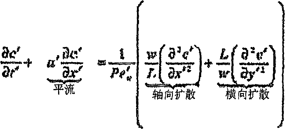
其中,L是转弯通道的长度,w是转弯通道的内部宽度,Pe’w是分散的佩克莱数;u’、c’、t’、x’和y’分别是标准化的速度、浓度、时间、轴向通道尺寸和横向通道尺寸。经测定,在本发明中Pe’w、L和w这三个参数对在倾斜通道的影响下分析物的倾斜和分散特别重要。Among them, L is the length of the turning channel, w is the inner width of the turning channel, Pe' w is the dispersed Peclet number; u', c', t', x' and y' are the normalized velocity, concentration, Time, axial channel size, and transverse channel size. It was determined that in the present invention the three parameters Pe'w , L and w are of particular importance for the tilting and dispersion of the analyte under the influence of the tilted channel.
佩克莱数(Pe)是一种无维度因数,代表某分析物的平流(或前向运动)和扩散的比例。如果Pe大,通过第一倾斜通道的倾斜峰可足够长时间地保持稳定的倾斜形状,而受相反方向的第二个转弯作用而转向。如果Pe小,倾斜通道中的倾斜峰可在较短时间中通过该通道的宽度扩散,将倾斜峰转变成弥散加宽的峰。在本发明方法中,可以最容易地使不感兴趣样品成分倾斜并扩散离开感兴趣分析物,例如,当倾斜通道中存在的条件所提供的佩克莱数大于倾斜通道长度与倾斜通道内部宽度的比值(即Pe>L/w)时。当这些条件所提供的佩克莱数比倾斜通道长度与倾斜通道宽度的比值高约0.01倍、0.1倍、1倍、10倍、100倍或更多时,可获得不感兴趣样品在倾斜通道中发生倾斜、扩散和分散的显著效果。The Peclet number (Pe) is a dimensionless factor that represents the ratio of advection (or forward motion) to diffusion for an analyte. If Pe is large, the sloping peak passing through the first sloping channel can maintain a stable sloping shape long enough to be turned by the second turn in the opposite direction. If Pe is small, a sloped peak in a sloped channel can diffuse across the width of the channel in a shorter time, converting the sloped peak into a diffusely broadened peak. In the method of the present invention, sample components not of interest can be most easily tilted and diffused away from the analyte of interest, for example, when the conditions present in the tilted channel provide a Peclet number greater than the ratio of the length of the tilted channel to the internal width of the tilted channel. Ratio (ie Pe>L/w). Samples of no interest in an inclined channel can be obtained when these conditions provide a Peclet number approximately 0.01, 0.1, 1, 10, 100, or more higher than the ratio of the inclined channel length to the inclined channel width Dramatic effects of tilting, spreading and dispersing occur.
影响佩克莱数的条件可以是,例如,影响分子在该通道中的平流和/或扩散的条件,如本领域技术人员所知的那样。例如,溶液粘度、凝胶的存在、温度、分子浓度、分子沿该通道迁移的速度、该通道直径等可影响Pe。调整控制平流和扩散的条件可提供能导致样品成分在通过本发明的倾斜通道区段期间和/或之后分散至所需水平的佩克莱数。Conditions affecting the Peclet number may be, for example, conditions affecting the advection and/or diffusion of molecules in the channel, as known to those skilled in the art. For example, solution viscosity, the presence of gels, temperature, molecular concentration, the speed at which molecules migrate along the channel, the channel diameter, etc. can affect Pe. Adjusting the conditions controlling advection and diffusion can provide a Peclet number that results in dispersion of sample constituents to desired levels during and/or after passage through the inclined channel segments of the present invention.
将堆积的分析物施加于分离通道Applying stacked analytes to the separation channel
可通过,例如施加跨分离通道区段和堆积的分析物的电场或压差将ITP所堆积的分析物注射入分离通道区段中。电场和/或电压可使分析物迁移或流入分离通道区段中。如上所述,可通过检测电压来触发施加电场或电压以提供一致性和功能性分析物的注射时机。施加于分离通道区段的电场或压差可与堆积通道区段中的电流消除同时进行。可设定(施加)电压和注射之间的时机,与通道、交界点和溶液区段的具体形状相符合。该时机在确定峰的分辨率和信号强度中可起到关键作用,因为它可影响移交后瞬时等速电泳持续的时间。The ITP-packed analyte can be injected into the separation channel segment by, for example, applying an electric field or a pressure differential across the separation channel segment and the stacked analyte. The electric field and/or voltage can cause the analyte to migrate or flow into the separation channel segment. As described above, detection of a voltage can trigger application of an electric field or voltage to provide consistent and functional analyte injection timing. The application of an electric field or a voltage differential to the separation channel segments can be performed simultaneously with the current removal in the stack channel segments. The voltage (applied) and the timing between injections can be set to conform to the specific shape of the channels, junctions and solution segments. This timing can play a key role in determining the resolution and signal strength of peaks, as it can affect how long the transient isotachophoresis lasts after handover.
分离通道区段可提供通过电泳分离分析物和/或通过选择性介质分离的条件。在优选实施方式中,分离通道区段具有微米级尺寸(例如,深度或宽度范围约为1000μm-0.1μm,或约为1000μm-1μm),例如,可快速分离小体积分析物样品。分离通道区段可含有能够对分析物的分离起作用的分离介质,例如pH梯度介质、大小选择性介质、离子交换介质、提高粘度的介质、疏水性介质等。Separation channel segments may provide conditions for separation of analytes by electrophoresis and/or separation by selective media. In preferred embodiments, the separation channel segments have micron-scale dimensions (eg, depth or width in the range of about 1000 μm-0.1 μm, or about 1000 μm-1 μm), eg, to allow rapid separation of small volume analyte samples. Separation channel segments may contain separation media capable of contributing to the separation of analytes, such as pH gradient media, size selective media, ion exchange media, viscosity increasing media, hydrophobic media, and the like.
分离通道区段(以及堆积通道区段)可含有提高粘度的介质如凝胶,以在不需要EOF的分离模式中降低电渗流(EOF)。分离通道区段可以独立于其它通道区段,或可与其它通道区段,例如加样通道区段和堆积通道区段共享通道所有的部分或一部分。在优选实施方式,分离通道区段是独立的,但在沿堆积通道区段长度的一些点上以液体接触相交。Separation channel segments (as well as stacking channel segments) may contain viscosity increasing media such as gels to reduce electroosmotic flow (EOF) in separation modes where EOF is not desired. Separation channel segments may be independent of other channel segments, or may share all or part of a channel with other channel segments, such as sample loading channel segments and stacking channel segments. In a preferred embodiment, the separation channel segments are independent but intersect in liquid contact at some point along the length of the stacking channel segments.
在典型实施方式中,当堆积通道区段和分离通道区段的交界点上检测到峰电压时,将经ITP分离的堆积分析物注射入分离通道区段中。例如,随着夹在拖尾电解质112和先行电解质113之间的堆积分析物111,在ITP中迁移通过分离通道区段与堆积通道区段交界处的伏特计接触点时,分离通道区段110中的空载电压达到最大(和电压改变的速率或电压图形的斜率变为零),如图11A所示。电压最大可触发堆积通道区段中ITP电场的消除,和在分离通道区段中施加电泳电场而诱导堆积的分析物111迁移(施加)进入分离通道区段中,如图11B所示。分析物迁移通过分离通道区段的选择性介质可在ITP期间使感兴趣分析物114与该分析物共同迁移通过堆积通道区段的不感兴趣样品成分115相分离(分辨),如图11C所示。在一些实施方式中,在ITP期间,例如可通过毛细管区带电泳使分离通道区段中堆积在一起或互相贴近的多种感兴趣分析物互相分离。In typical embodiments, the ITP-separated stacked analyte is injected into the separation channel segment when a peak voltage is detected at the junction of the stacking channel segment and the separation channel segment. For example, as the
本领域技术人员知道确定注射时机的另一方案。此方案可根据计算或模型,或可凭经验确定。例如,可将时间延误构建到触发的反应中,该反应基于通道体积、通道的几何形状、伏特计接触位置、电压的选择、与影响电压的溶液特性相关的分析物位置等。在一具体实施例中,分析物在瞬时ITP(还未达到稳定状态)中堆积拖尾电解质界面附近,而其余的样品溶液药团具有高电阻,合适的触发时间可以是电压峰后的某个时间,使堆积的分析物有额外的迁移时间到达与分离通道区段的交界点。Another scheme for timing injection is known to those skilled in the art. This scheme can be based on calculations or models, or can be determined empirically. For example, a time delay can be built into the triggered response based on channel volume, channel geometry, voltmeter contact location, choice of voltage, analyte location relative to solution properties that affect voltage, etc. In a specific embodiment, the analyte accumulates near the tailing electrolyte interface in the transient ITP (not reached a steady state), while the rest of the sample solution bolus has a high resistance, a suitable trigger time may be some time after the voltage peak Time, so that the accumulated analytes have additional migration time to reach the junction with the separation channel segment.
可沿分离通道区段自动施加电场(即不需要手动切换)。可通过,例如电子装置和本领域已知的算法实现这种自动施加电场。例如,可设置伏特计,使当接触点的电压达到设定水平时跳过开关。在优选实施方式中,可对逻辑装置,例如,集成电路或计算机进行编程,以根据设定的参数(例如,发生设定的电压)启动传动装置的开关。The electric field can be applied automatically (ie no manual switching is required) along the separation channel segment. Such automatic application of the electric field can be accomplished, for example, by electronic means and algorithms known in the art. For example, a voltmeter can be set to trip a switch when the voltage at a contact reaches a set level. In a preferred embodiment, a logic device, such as an integrated circuit or computer, can be programmed to actuate the switching of the transmission according to set parameters (eg, a set voltage occurs).
检测分析物Analyte detection
可检测分离通道区段中和/或从分离通道区段顺序洗脱后用本发明方法分离的分析物。可固定合适的检测器,例如,监测检测通道中的分析物,顺序扫描诸通道区段中的分析物,或提供整个通道的连续摄像。Analytes separated by the methods of the invention may be detected in the separation channel segment and/or after sequential elution from the separation channel segment. Suitable detectors can be fixed, for example, to monitor the analyte in the detection channel, to sequentially scan the analyte in the channel sections, or to provide continuous imaging of the entire channel.
合适的检测器常常由待检测分析物的类型所决定。常常可通过,例如分光光度法监测特定的吸收光波长来检测蛋白和核酸。可通过监测溶液电导率的改变来检测许多离子型感兴趣分析物。许多分析物具有荧光或可用荧光标记物来标记,用荧光计检测。可以用折射计检测溶液中的许多分析物,尤其是碳水化合物。The appropriate detector is often dictated by the type of analyte being detected. Proteins and nucleic acids can often be detected by monitoring specific wavelengths of light absorbed, eg, spectrophotometrically. Many ionic analytes of interest can be detected by monitoring changes in solution conductivity. Many analytes are fluorescent or can be labeled with a fluorescent marker for detection with a fluorometer. Many analytes in solution, especially carbohydrates, can be detected with a refractometer.
在一个典型实施方式中,可利用显微镜物镜聚焦于该通道的光电倍增管(PMT)监测透过分离通道区段的光源进行检测。本领域技术人员将理解,如何通过加入合适的激发光源,例如激光或灯泡的过滤光,将这种安排设置为荧光检测器。任选地,可将物镜装在X-Y扫描机上,监测微流体芯片上的任何位置。通过这种安排,可扫描分离通道区段长度中的沿pH梯度分离的分析物。在另一实施方式中,可跨分离通道出口安置电导计传感器,以在带电分析物从通道区段中洗脱出来时监测它们。In an exemplary embodiment, detection may be performed by monitoring the light source passing through the separation channel segment using a photomultiplier tube (PMT) with a microscope objective focused on that channel. Those skilled in the art will understand how to configure this arrangement as a fluorescence detector by adding a suitable excitation light source, such as a laser or filtered light from a bulb. Optionally, the objective lens can be mounted on an X-Y scanner to monitor any location on the microfluidic chip. With this arrangement, the length of the separation channel segment can be scanned for analytes separated along the pH gradient. In another embodiment, a conductometric sensor can be positioned across the separation channel outlet to monitor charged analytes as they elute from the channel segment.
检测器可以与数据储存装置和/或逻辑装置相连,以记录实验的运行。可将得自检测器,如PMT和电导计的模拟输出供给图表绘图机,以将分析物分离图形的踪迹保留在纸上。模数转换器可将检测信号传递给逻辑装置进行数据存储、分离图形的提供和/或试验评价。通过与回归分析的相应标准曲线作比较,数字逻辑装置可大大有助于分析物的定量。The detectors can be connected to data storage devices and/or logic devices to record the run of the experiment. Analog outputs from detectors such as PMTs and conductivity meters can be fed to a chart plotter to keep a trace of the analyte separation pattern on paper. The analog-to-digital converter may pass the detection signal to a logic device for data storage, provision of discrete patterns, and/or test evaluation. Digital logic devices can greatly assist in the quantification of analytes by comparison with corresponding standard curves for regression analysis.
分析物注射系统Analyte Injection System
本文所述的动电性分析物注射系统可提供灵敏的分析物检测,具有高度一致方式的高分辨率。可根据诸通道中电压的检测所确定的精确时机,将选择性堆积于堆积通道区段中的分析物注射(施加)到分离通道区段中。可通过提供自动注射子系统提高此精确性。The electrokinetic analyte injection system described herein provides sensitive analyte detection with high resolution in a highly consistent manner. Analytes selectively accumulated in stacking channel segments can be injected (applied) into separation channel segments with precise timing determined by detection of voltages in the channels. This accuracy can be increased by providing an automatic injection subsystem.
本发明系统通常包括,在通道中堆积分析物,与控制器通信和与通道一个或多个位置相接触的电压检测器,在电压检测器检测到所选电压时在通道中建立电流或压差,和将该电流或压差传输到控制器。该通道可包括相交的堆积通道区段和分离通道区段,形成连续的通道或共享公用通道部分。施加于分离通道区段被分离的分析物可以用与逻辑装置相连的检测器检测,以测定特定分析物的存在或评价分析物的量。Systems of the invention generally include, depositing analyte in a channel, a voltage detector in communication with a controller and in contact with one or more locations of the channel, and establishing a current or voltage differential in the channel when the voltage detector detects a selected voltage , and transmit that current or differential voltage to the controller. The channel may comprise intersecting stacked channel segments and separate channel segments forming a continuous channel or sharing a common channel portion. The separated analytes applied to the separation channel segment can be detected by a detector coupled to a logic device to determine the presence of a particular analyte or to assess the amount of an analyte.
通道aisle
本发明通道可以是,例如,包括加样区段、堆积区段、分离区段和/或检测区段的一条多功能通道。任选地,该通道可包括以交接点上液体接触但分开的加样通道区段、堆积通道区段和分离通道区段。在优选实施方式中,如图11示意图所示,加样通道区段是堆积通道区段的延伸,分离通道区段与堆积通道区段通过分析物注射的交界点以液体相接触。该系统的诸通道可以是本领域已知的任何通道,例如,管、柱、毛细管、微流体通道等。在优选实施方式中,例如,该通道是微流体芯片上的微米级通道。The inventive channel may be, for example, a multifunctional channel comprising a sample application section, a stacking section, a separation section and/or a detection section. Optionally, the channel may comprise a loading channel segment, a stacking channel segment and a separation channel segment that are in liquid contact at the junction but separate. In a preferred embodiment, as shown in the schematic diagram of FIG. 11 , the sample loading channel section is an extension of the stacking channel section, and the separation channel section and the stacking channel section are in liquid contact at the junction point where the analyte is injected. The channels of the system can be any channels known in the art, eg, tubes, columns, capillaries, microfluidic channels, and the like. In a preferred embodiment, for example, the channel is a microscale channel on a microfluidic chip.
可通过模型注射、光刻、蚀刻、激光消融等将微流体装置的通道包埋在基材表面上。这些通道可具有微米级尺寸,例如,深度或宽度的范围约为1000μm-0.1μm,或约为100μm-1μm。例如,可通过电渗流、毛细管作用(表面张力)、压差、重力等使液体在通道中流动。通道末端可在(例如)溶液孔中和/或在与其它通道或腔室的交界点上。通道的各端可具有电接触,以提供电场和/或电流来分离分析物或诱导EOF。检测器可与通道功能性相连,以监测感兴趣的参数,例如电压、电导率、电阻、电容、电流、折射率、光吸收、荧光、压力、流速等。微流体芯片可在功能性信息通讯上连接和用途上连接以支持仪器的使用,如电力连接、真空源、气压源、液压源、模拟和数字通讯线路、光纤等。The channels of the microfluidic device can be embedded on the substrate surface by mold injection, photolithography, etching, laser ablation, etc. These channels may have micron-scale dimensions, eg, a depth or width in the range of about 1000 μm-0.1 μm, or about 100 μm-1 μm. For example, liquids may be caused to flow in channels by electroosmotic flow, capillary action (surface tension), pressure differential, gravity, and the like. Channel ends can be, for example, in solution wells and/or at junctions with other channels or chambers. Each end of the channel can have electrical contacts to provide an electric field and/or current to separate analytes or induce EOF. Detectors can be functionally linked to the channels to monitor parameters of interest such as voltage, conductivity, resistance, capacitance, current, refractive index, light absorption, fluorescence, pressure, flow rate, and the like. Microfluidic chips can be connected in functional information communication and purpose to support the use of instruments, such as power connections, vacuum sources, air pressure sources, hydraulic sources, analog and digital communication lines, optical fibers, etc.
该通道可包括加样通道区段以将一个或多个体积的样品溶液引入该通道。可以本领域技术人员所知道的方式安置这种加样通道,例如注射器环,包括通向微流体芯片的收集管120,如图12所示,和/或冲洗通道区段,如图5A-5C的示意图所示。加样通道区段的横截面可大于堆积通道区段的横截面,如图7所示,以将大体积样品溶液中的分析物快速浓积在堆积通道区段入口附近。The channel may include a sample loading channel segment to introduce one or more volumes of sample solution into the channel. Such sample loading channels can be arranged in a manner known to those skilled in the art, such as syringe rings, including
本系统通道可包含凝胶状物质,它能有益地影响通道的迁移和流动特征,如2003年9月4日提交的美国专利申请序列号60/500,177,“减少迁移率变动试验的干扰”(Reduction of Migration Shift Assay Interference)中所述,将其全部内容纳入本文作为参考。可将凝胶掺入到通道中,以降低溶液的不良电渗流,同时为分离提供更佳的电泳特性。凝胶可通过减慢较大分子的泳动来影响分析物和/或电解质的相对迁移率。凝胶可作为工具帮助调节堆积通道区段中分析物和ITP电解质的迁移区带。例如,感兴趣分析物通常大于常用的ITP电解质。通过将凝胶置于堆积通道区段中,可使快速分析物(大但荷质比高)变慢,在先行电解质小分子盐或缓冲液之后迁移。任选地,凝胶可减慢分析物,使其迁移仅比拖尾电解质稍快。可通过(例如)改变凝胶类型、凝胶基质浓度和凝胶基质交联程度来调节凝胶对大分子迁移的阻抗。在堆积或分离通道区段中,凝胶可提高分析物的浓度和/或分辩率。在堆积通道区段或分离通道区段中可存在一种或多种不同凝胶。在实施本发明方法过程中,可采用各种不同凝胶,包括但不限于:聚丙烯酰胺凝胶、聚乙二醇(PEG)、聚环氧乙烷(PEO)、蔗糖和表氯醇的共聚物、聚乙烯吡咯烷酮(PVP)、羟乙基纤维素(HEC)、聚-N,N-二甲基丙烯酰胺(pDMA)或琼脂糖凝胶。在该装置的微流体通道中存在的凝胶浓度约为0.1-3.0%,例如0.9-1.5%。The channels of the present system may contain gel-like substances that beneficially affect the migration and flow characteristics of the channels, as described in U.S. Patent Application Serial No. 60/500,177, "Reducing Interference in Mobility Shift Assays," filed September 4, 2003 ( Reduction of Migration Shift Assay Interference), the entire contents of which are incorporated herein by reference. Gels can be incorporated into the channels to reduce undesirable electroosmotic flow of solutions while providing better electrophoretic properties for separations. Gels can affect the relative mobility of analytes and/or electrolytes by slowing down the mobility of larger molecules. The gel can be used as a tool to help tune the migration zones of analytes and ITP electrolytes in the stacking channel segment. For example, analytes of interest are often larger than commonly used ITP electrolytes. By placing the gel in a stacking channel segment, fast analytes (large but high charge to mass ratio) can be slowed down to migrate behind the preceding electrolyte small molecule salt or buffer. Optionally, the gel can slow down the analyte so that it migrates only slightly faster than the tailing electrolyte. The resistance of the gel to migration of macromolecules can be tuned by, for example, varying the gel type, gel matrix concentration, and degree of gel matrix crosslinking. In stacking or separation channel segments, the gel can increase the concentration and/or resolution of analytes. One or more different gels may be present in either the stacking channel segment or the separation channel segment. In carrying out the method of the present invention, various gels can be used, including but not limited to polyacrylamide gels, polyethylene glycol (PEG), polyethylene oxide (PEO), sucrose, and epichlorohydrin gels. Copolymer, polyvinylpyrrolidone (PVP), hydroxyethylcellulose (HEC), poly-N,N-dimethylacrylamide (pDMA) or agarose gel. The gel concentration present in the microfluidic channels of the device is about 0.1-3.0%, eg 0.9-1.5%.
堆积通道区段的功能是,例如,通过ITP选择性堆积感兴趣分析物,注射入分离通道区段作进一步分离和检测。堆积通道区段的各端上可具有电接触点,以施加适合于分析物堆积的电场。堆积通道区段可以与例如,外部驱动的气动或液压分支管液体相接触,从而可以实施上述“堆积感兴趣分析物”章节中所述的多次堆积技术的压力驱使的流动,如电解质加载或拖回。堆积通道区段可含有例如,适用于等速电泳(ITP)的电解质,如拖尾电解质、间隔电解质和/或先行电解质,如上述方法章节中所述。堆积通道区段可具有拖尾电解质孔18,如图1所示,和先行电解质孔19,以将电解质引入通道区段中。The function of the stacking channel segment is, for example, to selectively stack the analyte of interest via ITP for injection into the separation channel segment for further separation and detection. The stacking channel segments may have electrical contacts on each end to apply an electric field suitable for analyte stacking. Stacking channel segments may be in liquid contact with, for example, externally driven pneumatic or hydraulic manifolds, thereby enabling pressure-driven flow of multiple stacking techniques as described above in the "Stacking analytes of interest" section, such as electrolyte loading or Drag back. Stacking channel segments may contain, for example, electrolytes suitable for isotachophoresis (ITP), such as trailing electrolytes, spacer electrolytes, and/or leading electrolytes, as described in the Methods section above. The stacking channel segment may have trailing electrolyte holes 18, as shown in FIG. 1, and leading electrolyte holes 19 to introduce electrolyte into the channel segment.
分离通道区段可接受从堆积通道区段注射的堆积分析物,通过各种分离技术,例如增加ITP轮次、离子交换、大小排阻、疏水作用、反相层析、等电聚焦、毛细管区带电泳等进一步分离。分离通道区段可包括沿通道区段施加电场的电接触和/或驱使液体流动的外部连接电压源。分离通道区段可以是(例如)与堆积通道区段相交的通道区段、与堆积通道区段共有通道的通道区段和/或与堆积通道区段在功能上共享通道部分的通道区段。在典型实施方式中,分离通道区段与堆积通道区段在沿堆积通道区段长度上的一些点上相交,如图11所示。在这个实施方式中,将感兴趣的堆积分析物注射入分离通道区段后,不感兴趣样品成分可保留在分开的堆积通道区段部分中。在其它实施方式中,例如,堆积和分离通道区段可以在功能上位于一共同通道中,而没有插入的交界点。如图13A所示,通道区段中的堆积可持续直到检测到电压。一旦检测到该电压,可改变通道中的条件,以过渡到分离模式。这种过渡可包括(例如)在通道二末端130上施加压差,以导致分析物流入大小排阻树脂131中,如图13B所示。较小分子先于较大分子洗脱通过检测器132。过渡到分离模式的其它例子可包括(例如)电流流动方向的改变、液体流动方向的改变、将分离缓冲液注射入通道、电场电压的改变等。Separation channel segments accept stacked analytes injected from stacking channel segments by various separation techniques such as increased ITP rounds, ion exchange, size exclusion, hydrophobic interaction, reversed phase chromatography, isoelectric focusing, capillary zones Electrophoresis and other further separation. The separation channel segment may include electrical contacts to apply an electric field along the channel segment and/or an externally connected voltage source to drive fluid flow. The separation channel segment may be, for example, a channel segment that intersects the stacking channel segment, shares a channel with the stacking channel segment, and/or functionally shares a channel portion with the stacking channel segment. In an exemplary embodiment, the separation channel segment intersects the accumulation channel segment at some point along the length of the accumulation channel segment, as shown in FIG. 11 . In this embodiment, after injection of the bulk analyte of interest into the separation channel segment, sample components not of interest may remain in separate bulk channel segment portions. In other embodiments, for example, the stacking and separating channel segments may be functionally located in a common channel without intervening junctions. As shown in Figure 13A, buildup in the channel segment can continue until a voltage is detected. Once this voltage is detected, conditions in the channel can be changed to transition to split mode. Such a transition may include, for example, applying a pressure differential across the channel ends 130 to cause the analyte to flow into the
倾斜通道ITP系统Inclined channel ITP system
本发明的等速电泳系统可包括在堆积通道之中和/或之前的倾斜通道区段,用以提高感兴趣分析物与不感兴趣样品成分的分离。可分散样品成分,同时通过在倾斜通道中堆积聚集感兴趣分析物。例如,可转向通过累积的大角度、急转弯、横截面宽度较大的倾斜通道、具有不同长度相反表面形状的倾斜通道和/或具有使佩克莱数大于倾斜通道长度与倾斜通道宽度的比值的条件的倾斜通道系统,来提高分离效果。The isotachophoresis system of the present invention may include sloped channel sections within and/or prior to the stacking channel to improve separation of analytes of interest from sample components not of interest. Sample components can be dispersed while analytes of interest are concentrated by packing in inclined channels. For example, may steer through accumulated steep angles, sharp turns, inclined passages with large cross-sectional widths, inclined passages with different lengths and opposite surface shapes, and/or have a Peclet number greater than the ratio of inclined passage length to inclined passage width The condition of the inclined channel system to improve the separation effect.
提高倾斜通道区段中的倾斜和分散的一种方法是在通道中提供较大转角。在二维平面中,可利用(例如)连续的螺旋形弯道或转换成蛇形弯道来累积转角,如图14A-14C所示。螺旋形弯道的优点是,可通过在一个方向上累积大量转角,伴随地累积倾斜。螺旋形倾斜通道的缺点可能是弯道半径所固有的连续扩展变为有效性较低的曲率。螺旋形倾斜通道构造的困难也可能是与内部通道末端连接的进入问题。在螺旋形倾斜通道构造中提供进入通道末端的一种方法可以是加入能进出中心的并排螺旋通道,如图14B所示。或者,例如,可通过吸管或另一平面中的后通道以第三维度进入螺旋形通道末端,如图14A所示。对螺旋形通道长度的另一限制是优化倾斜所需的佩克莱数随螺旋形通道长度增加而增加。如图14C所示的蛇形倾斜通道可容易地通向通道末端,但产生的弯道可消除前面弯道造成的倾斜,尤其在各弯道之间的佩克莱数大或时间短的情况下。任选地,可采用三维倾斜通道,如螺旋和卷曲。One way to improve inclination and dispersion in inclined channel sections is to provide larger corners in the channel. In a two-dimensional plane, corners may be accumulated using, for example, continuous spiral turns or transitions into serpentine turns, as shown in FIGS. 14A-14C . The advantage of a spiral bend is that, by accumulating a large number of corners in one direction, a concomitant accumulation of inclines is possible. A disadvantage of a helically inclined channel may be that the inherent continuous expansion of the radius of the bend becomes a less effective curvature. Difficulties in the construction of helically inclined channels may also be an access problem connected to the end of the internal channel. One way to provide access to the end of the channel in a helical inclined channel configuration could be to incorporate side-by-side helical channels that can access the center, as shown in Figure 14B. Alternatively, the end of the helical channel can be accessed in a third dimension, eg, through a straw or a back channel in another plane, as shown in Figure 14A. Another limitation on the length of the helical channel is that the Peclet number needed to optimize the tilt increases with the length of the helical channel. A serpentine inclined channel as shown in Figure 14C can easily lead to the end of the channel, but the resulting curve can eliminate the tilt caused by the previous curve, especially when the Peclet number or time between the curves is large or short Down. Optionally, three-dimensional inclined channels such as spirals and coils can be used.
通过倾斜通道区段而产生的倾斜和分散可能在具有相对于通道内径形成的急转弯的通道中更明显。例如,流经通道内径与弯道宽度比值高的倾斜通道可提高倾斜作用。在一个实施方式中,当通道的沿弯道半径(倾斜通道的内部宽度)的横截面大于垂直于该弯道半径(倾斜通道的深度)的横截面时,提高了含有弯道的倾斜通道区段的倾斜作用。The inclination and divergence created by sloping channel sections may be more pronounced in channels with sharp turns formed relative to the inner diameter of the channel. For example, a sloped channel with a high ratio of flow channel inner diameter to bend width can enhance the tilting effect. In one embodiment, an inclined passage area containing a bend is increased when the cross-section of the passage along the radius of the bend (inner width of the inclined passage) is greater than the cross-section perpendicular to the radius of the bend (depth of the inclined passage). segment tilt.
倾斜通道区段的形状可影响迁移分析物的倾斜和分散。例如,对于通道表面外形,通过提高沿弯道外侧的移动距离与沿弯道内侧的移动距离之间的比例可提高倾斜作用。可通过增加弯道点的通道内部宽度与通道深度的比例来增加倾斜作用。如图15所示,在流经具有bolbus外侧弯道表面的弯道时,可使分析物150高度倾斜。当倾斜通道第一侧边151上的表面移动距离大于倾斜通道第二侧边152上的表面移动距离时,可增加倾斜通道中的倾斜作用,即使在整个倾斜通道上没有弯曲,如图16所示。例如,可从相反的表面移动距离差别范围在500%以上、到100%、到50%、到10%或更小获得明显的倾斜作用。The shape of the sloped channel segment can affect the slope and dispersion of migrating analytes. For example, for a channel surface profile, the tilt effect can be increased by increasing the ratio between the distance traveled along the outside of the curve and the distance traveled along the inside of the curve. The tilting effect can be increased by increasing the ratio of channel interior width to channel depth at the bend point. As shown in FIG. 15, the
在先行和拖尾电解质之间选择性堆积感兴趣分析物是本发明倾斜通道ITP系统的一个重要方面。可在倾斜期间和/或之后将感兴趣分析物连续重聚集于此二电解质之间,同时不感兴趣样品成分变得分散。可通过计算或经验数据了解感兴趣分析物的迁移率。可选择迁移率在感兴趣分析物和侵入性不感兴趣样品成分之间的拖尾和/或先行电解质。为提高分析物的聚集和不感兴趣样品成分的分散,可选择迁移率不同于不感兴趣样品成分但更接近感兴趣分析物的电解质。Selective stacking of analytes of interest between leading and trailing electrolytes is an important aspect of the present inclined channel ITP system. The analyte of interest can be continuously refocused between the two electrolytes during and/or after ramping, while sample components not of interest become dispersed. The mobility of an analyte of interest can be known from calculations or empirical data. Trailing and/or leading electrolytes can be selected with mobilities between the analyte of interest and invasive sample components of no interest. To improve the aggregation of analytes and the dispersion of sample components not of interest, an electrolyte may be selected that has a mobility different from that of the sample components not of interest but closer to the analyte of interest.
可将倾斜的ITP通道区段结合到上述系统和分析物的注射方法中。通过倾斜通道ITP分散其它样品成分后,可将较高纯度的感兴趣分析物注射入分离通道。一旦检测到电压,就可开始注射分析物。Slanted ITP channel segments can be incorporated into the systems and analyte injection methods described above. After dispersing other sample components through the inclined channel ITP, higher purity analytes of interest can be injected into the separation channel. Once the voltage is detected, analyte injection can begin.
利用间隔分子进行ITP和分离样品成分峰Utilizing Spacer Molecules for ITP and Separation of Sample Component Peaks
本发明提供了提高本发明等速电泳系统分辨灵敏度的额外技术。当采用荧光标记抗体偶联物以本发明所述内容进行迁移率变动免疫试验时,可发现这些额外技术的具体实用性,如2003年9月4日提交的题为“减少迁移率变动试验的干扰”(Reduction of Migration Shift Assay Interference)的共待审专利申请USSN60/500,177。迁移率变动免疫试验是检测和定量生物分子之间相关性的有用方法。例如,在电泳或层析试验中分子的保留时间的改变可表明存在着一种结合分子。结合可以是特异性的,例如抗体-抗原相互作用,或者是非特异性的,例如带正电分子的离子吸引于带负电的聚合物。The present invention provides additional techniques for increasing the resolution sensitivity of the isotachophoretic system of the present invention. These additional techniques may find particular utility when employing fluorescently labeled antibody conjugates to perform mobility shift immunoassays as described herein, as described in a paper entitled "Reducing Mobility Shift Assays," filed September 4, 2003. Co-pending patent application USSN60/500,177 for Reduction of Migration Shift Assay Interference. Mobility shift immunoassays are useful methods for detecting and quantifying correlations between biomolecules. For example, a change in the retention time of a molecule in an electrophoretic or chromatographic assay can indicate the presence of a bound molecule. Binding can be specific, such as an antibody-antigen interaction, or non-specific, such as the ion attraction of a positively charged molecule to a negatively charged polymer.
可在亲和性分子与分析物的其它相互作用中观察到迁移率变动。例如,当抗体与抗原结合时,或当多糖与凝集素结合时,可观察到迁移率变动。然而,由于这些分子有多种构象和不稳定的电荷密度,这些分子的层析或电泳常常产生宽大而分辨率差的峰。也可能各对亲和性分子/分析物存在多样性需要为各对开发专门的迁移率变动试验。如果在标准条件下进行的试验中将亲和性分子连接于能够高度可辨的运载体聚合物上就可避免这些问题。例如,日本专利申请号WO 02/082083“电泳方法”(Method for Electrophoresis)中描述了采用运载体/亲和分子的技术例子,将其全文纳入本文作为参考。虽然在迁移率变动试验中对亲和分子使用统一的运载体分子可提高分辨率,但问题是过量的标记抗体偶联物产生的峰干扰,尤其是采用大量过量的标记抗体偶联物来加速结合反应的动力学和提高试验的动态范围时。例如,加入过量的标记抗体偶联物所产生的问题是它常常可在电泳分离图案中产生大峰,此大峰可干扰结合于该偶联物(即抗原组合物)的抗原的检测,这种组合物被用于检测样品中抗原或分析物的存在。Mobility shifts can be observed in other interactions of the affinity molecule with the analyte. Mobility shifts are observed, for example, when antibodies are bound to antigens, or when polysaccharides are bound to lectins. However, due to the multiple conformations and unstable charge densities of these molecules, chromatography or electrophoresis of these molecules often produces broad and poorly resolved peaks. It is also possible that the diversity of each pair of affinity molecules/analytes requires the development of a specific mobility shift assay for each pair. These problems can be avoided if the affinity molecule is attached to a highly resolvable carrier polymer in assays performed under standard conditions. Examples of techniques using carrier/affinity molecules are described, for example, in Japanese Patent Application No. WO 02/082083 "Method for Electrophoresis", which is incorporated herein by reference in its entirety. While the use of uniform carrier molecules for affinity molecules in mobility shift assays improves resolution, the problem is peak interference from excess labeled antibody conjugates, especially with large excesses of labeled antibody conjugates to accelerate When combining the kinetics of a reaction and increasing the dynamic range of an experiment. For example, a problem with adding an excess of a labeled antibody conjugate is that it can often produce large peaks in the electrophoretic separation pattern that can interfere with the detection of antigen bound to the conjugate (i.e., antigen composition). are used to detect the presence of an antigen or analyte in a sample.
因此,迁移率变动试验中,尤其是采用亲和分子运载体的试验中仍然需要阻断或基本消除过量的标记偶联物迁移峰所造成的干扰的方法。本领域中描述了可用于解决这个问题的数种技术,如将第二抗体偶联物加入结合反应混合物中,进一步改变抗原复合物的迁移,使其远离抗体偶联物峰,如美国专利号5,948,231所述,将其全文内容纳入本文作为参考。此外,采用迁移率介于先行和拖尾电解质之间的间隔分子的等速电泳技术,可在抗体偶联物和抗原偶联物峰之间产生间隔,以帮助提高对这些峰的分辨率,参见例如Kopwillem,A.等,“利用氨基酸间隔物对血清蛋白质组分进行等速电泳”(Serum Protein Fractionation by Isotachophoresis UsingAmino Acid Spacers),J.Chroma.(1976)118:35-46和Svendsen,P.J.等,“在等速电泳系统中用安福林运载体两性电解质作为缓冲液和间隔离子分离蛋白质”(Separation of Proteins Using Ampholine Carrier Ampholytes as Buffer andSpacer Ions in an Isotachophoresis System),Science Tools,《KLB器械杂志》(KLB Instrument Journal)(1970)17:13-17中所述,将其全文内容纳入本文作为参考。Therefore, methods for blocking or substantially eliminating the interference caused by the migration peaks of excess labeled conjugates are still needed in mobility shift assays, especially in assays using affinity molecule carriers. Several techniques are described in the art that can be used to address this problem, such as adding a secondary antibody conjugate to the binding reaction mixture to further alter the migration of the antigen complex away from the antibody conjugate peak, as described in U.S. Patent No. 5,948,231, the entire contents of which are incorporated herein by reference. In addition, isotachophoresis using spacer molecules with a mobility between the leading and trailing electrolytes can create a space between the antibody conjugate and antigen conjugate peaks to help improve the resolution of these peaks, see For example Kopwillem, A. et al., "Serum Protein Fractionation by Isotachophoresis Using Amino Acid Spacers", J. Chroma. (1976) 118: 35-46 and Svendsen, P.J. et al. , "Separation of Proteins Using Ampholine Carrier Ampholytes as Buffer and Spacer Ions in an Isotachophoresis System", Science Tools, KLB Instruments Magazine (KLB Instrument Journal) (1970) 17:13-17, the entire contents of which are incorporated herein by reference.
然而,即使当采用这些技术时,发现当使用高浓度的标记抗体偶联物和样品(如混合的人血清样品)中存在少量分析物(如抗原)(如约1皮摩尔数量级或更少)时,抗体偶联物迁移峰可能仍趋于分散到抗原复合物区域中,而影响试验的检测灵敏度。However, even when employing these techniques, it has been found that when high concentrations of labeled antibody conjugates are used and small amounts of analyte (e.g., antigen) (e.g., on the order of about 1 picomolar or less) are present in the sample (e.g., pooled human serum sample), , the antibody conjugate migration peak may still tend to disperse into the antigen complex region, affecting the detection sensitivity of the assay.
本文所述的本发明内容可用于在将该复合物注入微流体装置的分离通道中之前(如,当将抗原复合物与样品中的其它污染成分相分离时),通过将偶联物与抗体复合物相分离来基本消除干扰来源的抗体偶联物。具体说,如下所述,揭示了将样品(如临床体液样品或组织样品)中感兴趣的第一种成分(如抗原复合物)与至少第二种成分(如过量的标记抗体偶联物)相分离的方法,该方法通常包括通过等速电泳在第一通道区段中堆积第一种和第二种成分;让堆积的第二种成分流过在交叉点上流体连接于第一通道区段的第二通道区段,检测该交叉点或附近与第一种和/或第二种堆积成分相对应的预先选定的电信号;和沿流体连接于交叉点的第三通道区段施加电场或压差,当检测到预先选定的的电信号时,将堆积的第一种成分引入第三通道区段。该方法还可包括在第三通道区段中将堆积的第一种成分分离成各种成分,并检测诸分离成分。The invention described herein can be used to combine the conjugate with the antibody before injecting the complex into the separation channel of the microfluidic device (for example, when separating the antigen complex from other contaminating components in the sample). Complex phase separation to substantially eliminate interfering sources of antibody conjugates. Specifically, as described below, it is disclosed that a first component (such as an antigen complex) of interest in a sample (such as a clinical body fluid sample or a tissue sample) is combined with at least a second component (such as an excess of a labeled antibody conjugate). A method of phase separation, the method generally comprising packing first and second components in a first channel section by isotachophoresis; flowing the packed second component through a region fluidly connected to the first channel at an intersection point A second channel section of the segment, detecting a preselected electrical signal corresponding to the first and/or second accumulation components at or near the intersection point; and applying The electric field or differential pressure, when a preselected electrical signal is detected, introduces the first component of the stack into the third channel segment. The method may also include separating the accumulated first component into components in the third channel section and detecting the separated components.
在一个具体实施方式中,堆积包括将先行电解质缓冲液、拖尾电解质缓冲液和含有间隔分子电泳迁移率介于先行电解质离子和拖尾电解质离子之间的间隔缓冲液引入第一通道区段,和通过等速电泳堆积第一种和第二种成分。该先行电解质可选自,例如氯化物、溴化物、氟化物、磷酸盐、乙酸盐、硝酸盐和二甲胂酸盐。拖尾电解质可选自,例如HEPES、TAPS、MOPS(3-(4-吗啉基)-1-丙烷磺酸)、CHES(2-(环己基氨基)乙烷磺酸)、MES(2-(4-吗啉基)乙烷磺酸)、甘氨酸、丙氨酸、β-丙氨酸等。间隔分子可选自,例如MOPS(3-(4-吗啉基)-1-丙烷磺酸)、安福林、氨基酸、MES、壬酸、D-葡糖醛酸、乙酰水杨酸、4-乙氧基苯甲酸、戊二酸、3-苯基丙酸、苯氧基乙酸、半胱氨酸、马尿酸、对羟基苯乙酸、异丙基丙二酸、衣康酸、柠康酸、3,5-二甲基苯甲酸、2,3-二甲基苯甲酸、对羟基肉桂酸和5-溴-2,4-二羟基苯甲酸,或者其它适合的间隔分子包括电泳迁移率在先行和拖尾电解质缓冲液中所存在离子之间的离子。这种间隔分子能在间隔分子与先行和拖尾电解质之间的离子前缘处堆积的第一种成分和堆积的第二种成分之间产生分隔区域。In a specific embodiment, stacking comprises introducing a leading electrolyte buffer, a trailing electrolyte buffer, and a spacer buffer containing spacer molecules having an electrophoretic mobility between the leading electrolyte ion and the trailing electrolyte ion into the first channel segment, and stack the first and second components by isotachophoresis. The leading electrolyte may be selected from, for example, chlorides, bromides, fluorides, phosphates, acetates, nitrates and cacodylates. The tailing electrolyte may be selected from, for example, HEPES, TAPS, MOPS (3-(4-morpholino)-1-propanesulfonic acid), CHES (2-(cyclohexylamino)ethanesulfonic acid), MES (2- (4-morpholino)ethanesulfonic acid), glycine, alanine, β-alanine, etc. The spacer molecule can be selected from, for example, MOPS (3-(4-morpholino)-1-propanesulfonic acid), amphetamine, amino acid, MES, nonanoic acid, D-glucuronic acid, acetylsalicylic acid, 4- Ethoxybenzoic acid, glutaric acid, 3-phenylpropionic acid, phenoxyacetic acid, cysteine, hippuric acid, p-hydroxyphenylacetic acid, isopropylmalonic acid, itaconic acid, citraconic acid, 3,5-Dimethylbenzoic acid, 2,3-dimethylbenzoic acid, p-hydroxycinnamic acid, and 5-bromo-2,4-dihydroxybenzoic acid, or other suitable spacer molecules including electrophoretic mobility prior and the ions present in the tailing electrolyte buffer. Such spacer molecules are capable of creating a separation region between the stacked first component and the stacked second component at the ion front between the spacer molecule and the leading and trailing electrolytes.
可通过产生跨第一和第二通道区段的电势进行样品的等速电泳,使第二种成分堆积,然后流入第二通道区段(在此处与感兴趣的第一种堆积成分相分离)。如上所述,第一种成分可包括,例如荧光标记的抗原-抗体复合物,第二种成分可包括荧光标记的抗体(如,标记的DNA-抗体偶联物)。优选第一种和第二种成分都带有电荷,其中第一种和第二种成分可以都带负电或都带正电,或者一种成分带正电另一种带负电。第一种和第二种带电成分也可选自,例如核酸、蛋白质、多肽、多糖和合成聚合物。Isotachophoresis of a sample can be performed by generating a potential across the first and second channel segments, causing the second component to accumulate and then flow into the second channel segment (where it is separated from the first accumulated component of interest). ). As noted above, the first component can include, for example, a fluorescently labeled antigen-antibody complex, and the second component can include a fluorescently labeled antibody (eg, a labeled DNA-antibody conjugate). Preferably both the first and second components are charged, wherein the first and second components may be both negatively charged or both positively charged, or one component may be positively charged and the other may be negatively charged. The first and second charged components may also be selected from, for example, nucleic acids, proteins, polypeptides, polysaccharides and synthetic polymers.
检测电信号的步骤可包括,例如检测第一和第二通道区段的交叉点上或其附近的光学信号、电压信号或电流信号。因此,通过使用等速电泳间隔分子以及可以诱捕分离自主要分离通道的侧通道中的不良成分迁移峰的微流体通道网络设计和测定脚本的组合,发现可大大提高从等速电泳获得的分辨率的灵敏度。The step of detecting an electrical signal may comprise, for example, detecting an optical signal, a voltage signal or a current signal at or near the intersection of the first and second channel sections. Thus, a combination of microfluidic channel network design and assay scripts using isotachophoretic spacer molecules that can trap undesirable component migration peaks in side channels separated from the main separation channel was found to greatly improve the resolution obtained from isotachophoresis sensitivity.
参见图17,显示了利用间隔分子进行等速电泳将不良成分峰与感兴趣的成分峰分开和分离得到感兴趣成分所用的示范性微流体芯片通道结构示意图。图17的微流体芯片含有一般命名为150的通道网络,其中包括许多通道或通道区段,其中几个的末端在缓冲液或电解质贮存室中。具体说,该通道网络包括末端在拖尾电解质缓冲液贮存室160中的通道区段162,末端在废液贮存室168中的通道区段166,末端在含有间隔缓冲液如MOPS的样品(和间隔缓冲液)贮存室174中的通道区段172,末端在废液贮存室180中的通道区段178,位于还连接于通道区段186和190的ITP堆积通道区段182和分离通道区段194的流体连接处的短互连通道区段184,其中通道区段186和190依次分别终止于间隔缓冲液贮存室188和先行电解质缓冲液贮存室192,以及分别终止于先行电解质缓冲液贮存室198和202的通道区段196和200。注意,各缓冲液贮存室的组成可因微流体芯片的具体用途而不同。先行电解质贮存室192、198和202中充满了含有电泳迁移率高于任何样品成分迁移率的离子的电解质溶液。拖尾电解质贮存室160中充满了含有电泳迁移率低于任何样品成分迁移率的电解质离子溶液。间隔缓冲液贮存室174和188中充满了含有电泳迁移率介于先行和拖尾电解质之间的电解质离子溶液。在这种情况下,将样品置入间隔缓冲液贮存室174中,含有至少两种不同的样品成分,如DNA抗体偶联物和抗原-DNA-抗体复合物。Referring to FIG. 17 , it shows a schematic diagram of an exemplary microfluidic chip channel structure for isotachophoresis using spacer molecules to separate undesired component peaks from interesting component peaks and to separate interested components. The microfluidic chip of Figure 17 contains a channel network, generally designated 150, comprising a number of channels or channel segments, several of which terminate in buffer or electrolyte reservoirs. Specifically, the channel network includes a
该微流体芯片也包括许多连接通道区段164、170和176,ITP堆积通道区段182和流体相连的分离通道区段194,这构成整个通道网络。将芯片的诸贮存室与真空(或压力)源连接,和/或接受一个电极,或这二者。例如,可在2001年2月23日提交的题为“多端口压力控制系统”(Multi-Port Pressure Control Systems)的共待审专利申请USSN 09/792,435中找到包括选择性和各自改变此系统各贮存室的压力和/或电压的多端口压力控制微流体装置和系统的例子,将其全部内容纳入本文作为参考。在使用时,当将电极置于相应的贮存室中时,例如将电极板置于基材上时可在基材上形成或独立地形成与相连的贮存室以液体相接触的电极。进而使各电极操作性连接于控制单元或电压控制器(未显示),以控制输出到各电极的电压(或电流)。也提供真空或压力源(未显示),它们给一个或多个相连的贮存室提供合适的真空(或压力)。可将多头贮存室压力控制器连接于多个独立控制的压力调节器,以影响液体在微流体通道网络各通道中的受压移动,如上述共待审专利申请USSN 09/792,435中所述。通过选择性控制和改变施加于微流体装置各贮存室的压力,可将交叉连接的微流体通道中液流精确地控制在所需流速。可将该受压流动与动电学液体控制相结合,从而提供复合的压力/动电学液流控制系统,用于将样品加样到该系统的通道中进行ITP试验。虽然图17中仅显示了一个单独的通道网络,应理解,该装置可包括通道网络阵列,各自具有上述通道网络的总体特征。The microfluidic chip also includes a number of connecting
将样品加到通道网络中,用等速电泳以间隔分子首先进行样品堆积步骤,优选用压力引起的流动控制加样,以帮助降低动电液体运输相关电场所引起的样品偏移作用。然而,应理解,本文描述的加样技术也可能必需依赖动电液体控制和运输(例如,当系统不具有多端口压力控制能力时)。首先对废液贮存室168和180施加真空,同时对贮存室188施加相应的反压力(或真空),以阻止间隔缓冲液流入通道区段186中。对贮存室168和180施加真空可停止电解质160流入并充满通道区段164,同时置于间隔缓冲液贮存室174中的样品将流入并充满通道区段170和176。此外,缓冲液贮存室192、198和202中的先行电解质将流入并充满通道区段182和194。因此,这种流动模式将使样品和间隔缓冲液夹在通道区段164中的拖尾电解质溶液和通道区段182和194中的先行电解质缓冲液之间。The sample is loaded into the channel network using isotachophoresis to space the molecules first for a sample stacking step, preferably with pressure-induced flow control loading to help reduce the effect of sample deflection due to the electric fields associated with electrokinetic fluid transport. However, it should be understood that the sampling techniques described herein may also necessarily rely on electrokinetic fluid control and transport (eg, when the system does not have multi-port pressure control capabilities). Vacuum is first applied to waste
为通过ITP使样品堆积在两个(或多个)小体积(例如对应于样品中的DNA抗体偶联物和抗原复合物),然后在与贮存室160和192液体接触的电极之间建立正电压梯度,随着样品移动通过各通道区段,这样使170、176和主要堆积通道区段182中发生ITP。间隔缓冲液(在图18A-D中称为“SP”)可在样品中,例如此时在堆积的抗体偶联物峰210和堆积的抗原复合物峰212之间,在间隔与先行和拖尾电解质缓冲液(在图18A-D中分别称为“L”和“T”)之间的离子前缘处,提供了两个堆积体积210和212之间的分隔区域。图18A-D和图19中最好地说明了这一点。允许比抗原复合物峰212移动更快的抗体偶联物峰210首先迁移到侧通道184中,通过通道区段190向贮存室192移动。电压检测器(如伏特计)和/或光学检测器安置处能与通道区段188和192的交叉点187发生传感器通信,在样品通过交叉点187时监测样品的电压信号和/或光学信号。本文所用的短语“传感器通信”指安置在能接受特定位置(例如微米级通道)的特定信号位置上的检测系统。例如,就光学检测器而言,传感器通信指安置在所述微米级通道或者液流交叉点或连接点透明区域附近的检测器,这种设置使该光学检测器能接受并检测此通道的光学信号,例如荧光、化学发光等。这种结构一般包括采用位于足够接近流动控制元件或通道之处能收集到可检测水平的光学信号的合适物镜和光具系列。显微镜检测器,如荧光检测器是本领域熟知的。参见,例如,美国专利号5,274,240和5,091,652,各自纳入本文作为参考。To stack the sample in two (or more) small volumes (e.g., corresponding to the DNA-antibody conjugate and antigen complex in the sample) by ITP, a positive electrode is then established between electrodes in fluid contact with
如上所述,当在与堆积的第二种成分210对应的交叉点187处检测到峰电压时,该检测到的电压信号可通过合适方法触发贮存室160和192之间产生的ITP电场消除,随后在分离通道区段194中施加毛细管电泳(CE)电场以诱导堆积的第一种成分峰212迁移(施加)到分离通道区段中,如图18C-D所示。为了确定上述切换电压梯度的时间,可采用交叉点187(或例如图19的芯片结构的ITP堆积通道区段182和分离通道区段194的流体连接交叉点)的电压、电流和/或光学信号数据。根据以下所述的这些数据,然后可将电压梯度切换到贮存室188和202之间,而允许与贮存室192接触的电极空载,使得在通道区段190中没有电流。As mentioned above, when a peak voltage is detected at the
图20A-C显示了用等速电泳以合适的间隔分子互相分离的DNA-抗体偶联物和抗原复合物的示范性电压和光学特性,和类似于图17的微流体通道网络。如图所示,样品中的诸成分分别产生了两个光学最大值216和218,和电压信号220和222分别产生了两个电压斜率改变。光学最大值信号216、218和随后出现的电压斜率改变220、222彼此发生在大约半秒内,如图20B-C所示。换句话说,在第一个光学最大值216出现后大约1/2秒发生了第一个电压斜率改变220,在第二个光学最大值218出现后大约1/2秒发生了第二个电压斜率改变222。因此,可利用测量到电压斜率改变220、222(和/或光学信号最大值216、218)之一的出现,将电压梯度改变的切换信号从该试验ITP相的孔160和192切换到该试验分离相的孔188和202。通过控制缓冲液和间隔电解质的相对电导率,可控制电压斜率的大小,以使上述测量易于进行。20A-C show exemplary voltage and optical properties of DNA-antibody conjugates and antigen complexes separated from each other with suitable spacer molecules using isotachophoresis, and a microfluidic channel network similar to that of FIG. 17 . As shown, components in the sample produce two
参见图21,也观察到在某些试验结构中,电压(和光学信号图形)包括两种以上,例如三种以上不同的电压斜率改变,它们互相发生在相对接近(例如,约1/2秒级或更短)的时间。已证明这是在微流体装置中进行甲胎蛋白(AFP)检测的免疫试验所发生的情况,甲胎蛋白是胎儿早期血浆蛋白,功能相当于白蛋白,由胎儿卵黄囊、肝脏和胃肠道产生,如2003年9月4日提交的题为“减少迁移率变动试验的干扰”(Reduction of Migration Shift Assay Interference)的共待审美国申请序列号60/500,177所述,此前已将其纳入本文作为参考。在AFP免疫试验时,常需要区分和比较各种AFP组分的不同水平。通过凝集素-亲和电泳(采用兵豆凝集素LCA)可将AFP分为至少3种组分。LCA将AFP分成三条条带:LCA-无反应性(AFP-L1)、弱反应性(AFP-L2);以及强反应性(AFP-L3)。Referring to FIG. 21, it was also observed that in some experimental configurations, the voltage (and optical signal pattern) included two or more, such as more than three, different voltage slope changes that occurred relatively close to each other (e.g., about 1/2 second grade or less). This has been shown to be the case in immunoassays in microfluidic devices for the detection of alpha-fetoprotein (AFP), an early fetal plasma protein that is functionally equivalent to albumin and produced by the fetal yolk sac, liver and gastrointestinal tract produced, as described in co-pending U.S. Application Serial No. 60/500,177, entitled "Reduction of Migration Shift Assay Interference," filed September 4, 2003, and previously incorporated herein Reference. In the AFP immunoassay, it is often necessary to distinguish and compare the different levels of various AFP components. AFP can be separated into at least 3 components by lectin-affinity electrophoresis (using lentil agglutinin LCA). LCA divides AFP into three bands: LCA-non-reactive (AFP-L1), weakly reactive (AFP-L2); and strongly reactive (AFP-L3).
例如,已证明,AFP L1与AFP L3的相对水平比较,可用作肝细胞癌的标记,总AFP可用作怀孕妇女可能怀有神经管缺陷婴儿的标记。进行AFP免疫试验时采用DNA-抗体偶联物来捕获微流体系统中感兴趣的各种AFP组分,如上述USSN60/500,177中所详述,虽然任何一个电压斜率改变都可用于将电压梯度改变信号从孔160和192切换到该试验CE分离相的孔188和202,但是据观察,采用最后产生的电压导数(例如,对于四种专利样品各自通过该装置而言,图21中显示了第三个不同的电压改变224)可提供触发该切换的最佳结果。For example, it has been demonstrated that relative levels of AFP L1 compared to AFP L3 can be used as a marker for hepatocellular carcinoma, and total AFP can be used as a marker for a pregnant woman who may be carrying a baby with neural tube defects. AFP immunoassays employ DNA-antibody conjugates to capture various AFP components of interest in microfluidic systems, as detailed in the
感兴趣的第一种堆积成分212迁移通过分离通道区段194可通过毛细管区带电泳分离(分辨)样品中的感兴趣成分214,如图18D所示。通过将间隔缓冲液经贮存室188和通道区段186(和184)引入分离通道区段194中,将把第一种堆积的成分212夹在其上游的间隔缓冲液和下游液体边界之间,这会导致去堆积作用和使堆积成分212与该试验ITP相期间堆积在ITP堆积通道区段182中的其它污染物质相分离。Migration of the first bulk component of
因为也许不可能将所有堆积的第二种成分210转移到通道区段184中,导致在分离通道区段194中有一些堆积成分210的遗留物,在分离通道区段中存在作为拖尾缓冲液的间隔缓冲液,将意味着分离通道中的不良遗留物成分210将被夹在较慢的分隔缓冲液和较快的先行电解质缓冲液之间,这将使其进一步堆积于分离通道区段194中。因此,该ITP界面的自身灵敏特性将最大程度减少分离通道区段中存在第二种成分210遗留物所引起的干扰和移动较快的成分210扩散进入移动较慢的成分峰212中。以这种方式,可基本上将实质量的成分210,和与感兴趣成分212(如抗原复合物)堆积在一起可能干扰迁移率变动试验的不感兴趣的任何其它标记物质,与堆积成分212相分离。这可显著降低影响分离通道区段检测区域基线信号的物质的量,从而提高该试验的灵敏度。应注意,各种缓冲液中存在的筛选介质可帮助调节该试验ITP相期间感兴趣成分的迁移率,也可提高该试验CE相期间污染物质与成分212相分离的效果。Because it may not be possible to transfer all of the accumulated
为了进一步使偶联物遗留成分峰进入分离通道区段194可能造成的干扰减至最小,可采用图19所示的通道网络结构的另一实施方式,此方式中取消了将通道区段186和190与ITP堆积通道区段182和分离通道区段194流体相连接的互连通道区段184。在此替代实施方式中,将电压检测器和/或光学检测器置入与ITP堆积通道区段182和分离通道区段194之间流体连接的传感器通信中。此外,在该具体实施方式中,利用在分离通道区段194中检测到对应于感兴趣的成分峰212的第二个电压斜率改变222(或第二个光学最大值218)来触发将电压梯度从该试验的ITP相切换到该试验的CE相,可保证几乎所有的第二种成分210进入侧通道190中,在此将其丢弃到液体贮存室192中。在本发明另一实施方式中,通道区段186也可与通道区段190的对侧通道区段182、194相交和位于其上。In order to further minimize the interference that the residual component peak of the conjugate enters the
电压检测器voltage detector
可使本发明系统中的电压检测器与各通道接触,以检测传输给控制器的电压。电压检测器的类型和复杂性可取决于(例如)通道硬件的配置和待检测电压的类型。Voltage detectors in the system of the present invention can be brought into contact with each channel to sense the voltage delivered to the controller. The type and complexity of the voltage detector may depend, for example, on the configuration of the channel hardware and the type of voltage to be detected.
电压检测器的范围可包括,例如简单的受电压作用而跳闸的继电器开关,模拟检流计,装有图表记录器的模拟装置,具有数字输出的伏特计,通过逻辑装置进行评价。伏特计通常可检测两个位置电极之间,例如,通道中和地面的接触位置或通道中两个不同位置之间的电压电势。与通道相接触的电压电极的位置可改变堆积运作期间检测到的电压图形。然而,可能常常要为范围广阔的通道位置上的伏特计接触点(例如,伏特计接触点不一定在堆积和分离通道区段之间的交界点上)确定连贯一致地和明确地触发注射所需的定义明确的电压。Voltage detectors may range from, for example, simple relay switches tripped by voltage, analog galvanometers, analog devices with chart recorders, voltmeters with digital outputs, evaluation by logic devices. A voltmeter typically detects a voltage potential between electrodes at two locations, for example, a contact location in a channel and ground or between two different locations in a channel. The position of the voltage electrodes in contact with the channels can change the voltage pattern detected during the stacking operation. However, it may often be determined for voltmeter contacts over a wide range of channel locations (e.g., voltmeter contacts not necessarily at the junction between stacked and separated channel segments) to consistently and unambiguously trigger injection. well-defined voltage.
在一个实施方式中,伏特计接触处可位于通道两端。因为电阻相对高的拖尾电解质在通道中取代了先行电解质,维持所选电流流过该通道需要的电压可能要提高。在这种情况下,触发注射的电压可以是(例如)设定的电压。In one embodiment, voltmeter contacts may be located at both ends of the channel. As the relatively high-resistance trailing electrolyte displaces the leading electrolyte in the channel, the voltage required to maintain the selected current flowing through the channel may have to increase. In this case, the voltage that triggers the injection may be, for example, a set voltage.
在另一实施方式中,可将伏特计接触点定位在地面(或其它参比电压)上和与堆积通道区段相交的分离通道区段的任何点上。如果不允许电流流过分离通道区段(例如空载电压使分离通道区段维持零电流时或分离通道区段不是整个电路的一部分时),分离通道区段中的任何位置将反映堆积通道区段交界处的电压。随着TE/LE界面通过该交界处,在分离通道区段中检测到的电压可升高到峰值然后降低,其方式类似于图8的电压图形,如本领域技术人员所知道的那样。In another embodiment, the voltmeter contacts can be positioned on ground (or other reference voltage) and on any point of the separation channel segment that intersects the stacking channel segment. If current is not allowed to flow through the split channel segment (such as when the no-load voltage maintains the split channel segment at zero current or when the split channel segment is not part of the overall circuit), any location in the split channel segment will reflect the stacked channel region The voltage at the segment junction. As the TE/LE interface passes the junction, the voltage detected in the separation channel segment may rise to a peak and then fall in a manner similar to the voltage graph of Figure 8, as known to those skilled in the art.
在无电流和与堆积通道区段接触的分离通道区段中监测电压时,缺少电流可能由于(例如)空载电压的调节或电路分隔所引起。空载电压调节装置可以是本领域已知的电子设备,它能检测电流在通道区段中的流动,并对该通道区段施加电压,以中和任何跨该通道区段的电压电势,从而阻止电流流动。可任选地设置空载电压调节器,以调节该通道区段的压差,在该通道区段中提供选择的恒定电流。阻止电流在通道区段中流动的另一种方法是确保该通道区段不是整个电路的一部分。例如,可将电开关安置于该通道区段的一端,以选择性打开或关闭任何相关电路。When voltage is monitored in no current flow and isolated channel segments in contact with stacked channel segments, the lack of current flow may be caused by, for example, adjustment of the no-load voltage or circuit separation. The no-load voltage regulating means may be an electronic device known in the art that senses the flow of current in a channel segment and applies a voltage to the channel segment to neutralize any voltage potential across the channel segment, thereby prevent the flow of current. An unloaded voltage regulator may optionally be provided to regulate the differential voltage across the channel segment providing a selected constant current in the channel segment. Another way to prevent current flow in a channel segment is to ensure that the channel segment is not part of the overall circuit. For example, an electrical switch may be placed at one end of the channel segment to selectively open or close any associated electrical circuits.
可将伏特计与控制器相连接,以启动将分析物施加(注射)于分离通道区段。启动注射可以手动或自动。例如,伏特计可为系统操作员(控制员)提供可视电压读数,使其一旦观察到电压(如选择的电压或电压峰)时,即可手动转换通道的电场或液体流动。在另一实施例中,控制器是一种数字逻辑设备,与伏特计电连接并设置为一旦检测到所选电压时自动将堆积的分析物施加到分离通道区段。A voltmeter can be connected to the controller to initiate the application (injection) of the analyte to the separation channel segment. Initiation of the injection can be manual or automatic. For example, a voltmeter can provide a visual voltage readout to a system operator (controller) who can manually switch a channel's electric field or fluid flow once a voltage (such as a selected voltage or voltage peak) is observed. In another embodiment, the controller is a digital logic device electrically connected to the voltmeter and configured to automatically apply the stacked analyte to the separation channel segment upon detection of a selected voltage.
分析物检测器Analyte detector
可将合适的分析物检测器掺入到本发明系统中以检测分析物。检测器的类型和构型取决于(例如)待检测分析物的类型和/或通道设计。可将分析物检测器与逻辑装置相连来储存分析物的检测图形和评价分析结果。Suitable analyte detectors may be incorporated into the systems of the invention to detect analytes. The type and configuration of the detector depends, for example, on the type of analyte to be detected and/or the channel design. The analyte detector can be connected to a logic device to store the analyte detection profile and evaluate the analysis results.
本系统可检测的分析物范围可以很广,许多是带电分子或经修饰而带有电荷的分子。例如,感兴趣分析物可以是蛋白质、核酸、碳水化合物、糖蛋白、离子等。虽然可用另一种机制,如大小排阻产生堆积,但在本发明的许多系统中,通过带电分析物在电场中的迁移来驱动堆积。本领域技术人员知道,不带电的感兴趣分析物可通过适当地调整pH或用带电化学基团衍生的分析物接受电荷进行电泳堆积。The system can detect a wide range of analytes, many of which are charged molecules or molecules modified to be charged. For example, analytes of interest can be proteins, nucleic acids, carbohydrates, glycoproteins, ions, and the like. In many systems of the present invention, accumulation is driven by migration of charged analytes in an electric field, although another mechanism, such as size exclusion, can be used to produce accumulation. Those skilled in the art know that uncharged analytes of interest can be electrophoretically stacked by appropriate adjustment of the pH or by accepting a charge with an analyte derivatized with an electrochemical group.
本系统中的分析物检测器可以是本领域已知的任何合适的检测器。例如,检测器可以是荧光计、分光光度计、折光计、电导计等。用可得到的检测器不能检测的分析物常常可用标记分子衍生而赋予其可检测性。可安置检测器或使其聚焦监测通道区段,包括交界点和/或分离通道区段中的分析物。检测器可在分析物流出分离通道区段时,例如在腔室的检测通道中,监测这些分析物。The analyte detector in the system can be any suitable detector known in the art. For example, the detector can be a fluorometer, spectrophotometer, refractometer, conductivity meter, or the like. Analytes that are not detectable with available detectors can often be derivatized with a labeling molecule to render them detectable. Detectors may be positioned or focused to monitor channel segments, including junctions and/or separate analytes in channel segments. The detector can monitor the analytes as they flow out of the separation channel segment, for example in the detection channel of the chamber.
分析物检测器可监测通道位置,顺序扫描通道长度,或提供分离的分析物的连续图像。在一个实施方式中,静置的分光光度检测器可以是聚焦于具体通道位置或交界点的光电倍增管。在另一实施方式中,分析物检测器可以是聚焦于微通道的荧光计,通过安置在X-Y输送机上的共聚焦显微镜物镜顺序扫描微流体装置通道中分离的分析物。在另一实施方式中,分析物检测器可以是能够在多个分离腔室中一次提供许多分离图像的电耦装置(CCD)阵列。Analyte detectors can monitor channel position, scan channel length sequentially, or provide continuous images of separated analytes. In one embodiment, the stationary spectrophotometric detector may be a photomultiplier tube focused on a specific channel location or junction. In another embodiment, the analyte detector can be a fluorometer focused on the microchannel, sequentially scanning the separated analytes in the channel of the microfluidic device through a confocal microscope objective mounted on an X-Y conveyor. In another embodiment, the analyte detector may be a charge coupled device (CCD) array capable of providing many separation images at a time in multiple separation chambers.
可将分析物检测器与逻辑装置相连来储存和评价分析结果。该系统的逻辑装置可包括,例如图表记录器、晶体管、电路板、集成电路、中央处理器、计算机监视器、计算机系统、计算机网络等。计算机系统可包括,例如具有可输入软件系统的数据组和指令组的数字计算机硬件。该计算机可与检测器相连,以评价分析物的存在、身份、数量和/或位置。该计算机可以是,例如PC(Intel x86或奔腾芯片-与


应理解,本文所述实施例和实施方式的目的只是说明,本领域技术人员根据这些内容作出的各种修改或改变,应包括在本申请的精神和范围内以及所附权利要求的范围内。It should be understood that the purpose of the examples and implementations described herein is only for illustration, and various modifications or changes made by those skilled in the art based on these contents shall be included in the spirit and scope of the present application and the scope of the appended claims.
虽然为了阐明和理解的目的详述了上述发明,本领域技术人员应明白,通过阅读本文公开的内容,可作出各种形式和细节的改变,而不背离本发明的真实范围。例如,可以各种组合使用上述许多技术和装置。Although the foregoing invention has been described in detail for purposes of illustration and understanding, those skilled in the art will understand from the disclosure herein that various changes in form and detail may be made without departing from the true scope of the invention. For example, many of the techniques and devices described above can be used in various combinations.
将本申请中所引用的所有发表物、专利、专利申请和/或其它文档的内容纳入作为参考用于所有目的,其程度正如单独地将各发表物、专利、专利申请和/或其它文档纳入作为参考用于所有目的。The contents of all publications, patents, patent applications and/or other documents cited in this application are incorporated by reference for all purposes to the same extent as if each individual publication, patent, patent application and/or other document were individually incorporated Used as a reference for all purposes.
Claims (33)
Applications Claiming Priority (2)
| Application Number | Priority Date | Filing Date | Title |
|---|---|---|---|
| US53204203P | 2003-12-23 | 2003-12-23 | |
| US60/532,042 | 2003-12-23 |
Publications (2)
| Publication Number | Publication Date |
|---|---|
| CN1906483A CN1906483A (en) | 2007-01-31 |
| CN100562745C true CN100562745C (en) | 2009-11-25 |
Family
ID=34794221
Family Applications (1)
| Application Number | Title | Priority Date | Filing Date |
|---|---|---|---|
| CNB2004800326937A Expired - Lifetime CN100562745C (en) | 2003-12-23 | 2004-06-12 | Analyte injection system |
Country Status (8)
| Country | Link |
|---|---|
| US (1) | US20050133370A1 (en) |
| EP (1) | EP1697732A1 (en) |
| JP (1) | JP2007518977A (en) |
| KR (3) | KR100852348B1 (en) |
| CN (1) | CN100562745C (en) |
| AU (1) | AU2004313572B2 (en) |
| RU (1) | RU2006126664A (en) |
| WO (1) | WO2005068993A1 (en) |
Cited By (1)
| Publication number | Priority date | Publication date | Assignee | Title |
|---|---|---|---|---|
| CN110044988A (en) * | 2019-04-26 | 2019-07-23 | 常州大学 | A kind of method of tortuous capillary electrophoresis detection multienzyme |
Families Citing this family (86)
| Publication number | Priority date | Publication date | Assignee | Title |
|---|---|---|---|---|
| US6048734A (en) | 1995-09-15 | 2000-04-11 | The Regents Of The University Of Michigan | Thermal microvalves in a fluid flow method |
| US6692700B2 (en) | 2001-02-14 | 2004-02-17 | Handylab, Inc. | Heat-reduction methods and systems related to microfluidic devices |
| US8895311B1 (en) | 2001-03-28 | 2014-11-25 | Handylab, Inc. | Methods and systems for control of general purpose microfluidic devices |
| US7829025B2 (en) | 2001-03-28 | 2010-11-09 | Venture Lending & Leasing Iv, Inc. | Systems and methods for thermal actuation of microfluidic devices |
| US7010391B2 (en) | 2001-03-28 | 2006-03-07 | Handylab, Inc. | Methods and systems for control of microfluidic devices |
| US7323140B2 (en) | 2001-03-28 | 2008-01-29 | Handylab, Inc. | Moving microdroplets in a microfluidic device |
| US6852287B2 (en) | 2001-09-12 | 2005-02-08 | Handylab, Inc. | Microfluidic devices having a reduced number of input and output connections |
| WO2004094986A2 (en) * | 2003-04-16 | 2004-11-04 | Handylab, Inc. | System and method for electrochemical detection of biological compounds |
| EP2407243B1 (en) | 2003-07-31 | 2020-04-22 | Handylab, Inc. | Multilayered microfluidic device |
| CA3198754A1 (en) | 2004-05-03 | 2005-11-17 | Handylab, Inc. | A microfluidic device and methods for processing polynucleotide-containing samples |
| US8852862B2 (en) | 2004-05-03 | 2014-10-07 | Handylab, Inc. | Method for processing polynucleotide-containing samples |
| EP1747453B1 (en) * | 2004-05-13 | 2009-09-02 | Agilent Technologies, Inc. | Controlling sample loading of a specimen |
| WO2006098700A1 (en) * | 2005-03-18 | 2006-09-21 | Nanyang Technological University | Microfluidic sensor for interfacial tension measurement and method for measuring interfacial tension |
| JP2006317357A (en) * | 2005-05-13 | 2006-11-24 | Shimadzu Corp | Microchip electrophoresis method and apparatus |
| US20100064780A1 (en) * | 2005-07-27 | 2010-03-18 | Howard A Stone | Pressure Determination In Microfludic Systems |
| US10900066B2 (en) | 2006-03-24 | 2021-01-26 | Handylab, Inc. | Microfluidic system for amplifying and detecting polynucleotides in parallel |
| US7998708B2 (en) | 2006-03-24 | 2011-08-16 | Handylab, Inc. | Microfluidic system for amplifying and detecting polynucleotides in parallel |
| US11806718B2 (en) | 2006-03-24 | 2023-11-07 | Handylab, Inc. | Fluorescence detector for microfluidic diagnostic system |
| ES2692380T3 (en) | 2006-03-24 | 2018-12-03 | Handylab, Inc. | Method to perform PCR with a cartridge with several tracks |
| US7951278B2 (en) * | 2006-07-20 | 2011-05-31 | The Board Of Trustees Of The Leland Standford Junior University | Method of detecting directly undetectable analytes using directly detectable spacer molecules |
| US8562804B2 (en) | 2006-07-20 | 2013-10-22 | The Board Of Trustees Of The Leland Stanford Junior University | Fluorescent finger prints for indirect detection in isotachophoresis |
| US8765076B2 (en) | 2006-11-14 | 2014-07-01 | Handylab, Inc. | Microfluidic valve and method of making same |
| WO2008060604A2 (en) | 2006-11-14 | 2008-05-22 | Handylab, Inc. | Microfluidic system for amplifying and detecting polynucleotides in parallel |
| US8105783B2 (en) | 2007-07-13 | 2012-01-31 | Handylab, Inc. | Microfluidic cartridge |
| US9186677B2 (en) | 2007-07-13 | 2015-11-17 | Handylab, Inc. | Integrated apparatus for performing nucleic acid extraction and diagnostic testing on multiple biological samples |
| US9618139B2 (en) | 2007-07-13 | 2017-04-11 | Handylab, Inc. | Integrated heater and magnetic separator |
| US20090136385A1 (en) | 2007-07-13 | 2009-05-28 | Handylab, Inc. | Reagent Tube |
| US8182763B2 (en) | 2007-07-13 | 2012-05-22 | Handylab, Inc. | Rack for sample tubes and reagent holders |
| USD621060S1 (en) | 2008-07-14 | 2010-08-03 | Handylab, Inc. | Microfluidic cartridge |
| US8133671B2 (en) | 2007-07-13 | 2012-03-13 | Handylab, Inc. | Integrated apparatus for performing nucleic acid extraction and diagnostic testing on multiple biological samples |
| WO2009012185A1 (en) | 2007-07-13 | 2009-01-22 | Handylab, Inc. | Polynucleotide capture materials, and methods of using same |
| US8287820B2 (en) | 2007-07-13 | 2012-10-16 | Handylab, Inc. | Automated pipetting apparatus having a combined liquid pump and pipette head system |
| US8016260B2 (en) | 2007-07-19 | 2011-09-13 | Formulatrix, Inc. | Metering assembly and method of dispensing fluid |
| US20090166201A1 (en) * | 2007-12-28 | 2009-07-02 | General Electric Company | Injection method for microfluidic chips |
| CN101270381B (en) * | 2008-05-14 | 2011-04-13 | 肖水清 | Multiple PCR fast detecting method for oral cavity pathogen |
| USD618820S1 (en) | 2008-07-11 | 2010-06-29 | Handylab, Inc. | Reagent holder |
| USD787087S1 (en) | 2008-07-14 | 2017-05-16 | Handylab, Inc. | Housing |
| WO2010040227A1 (en) | 2008-10-10 | 2010-04-15 | The Governing Council Of The University Of Toronto | Hybrid digital and channel microfluidic devices and methods of use thereof |
| US8100293B2 (en) | 2009-01-23 | 2012-01-24 | Formulatrix, Inc. | Microfluidic dispensing assembly |
| US8846314B2 (en) * | 2009-03-03 | 2014-09-30 | The Board Of Trustees Of The Leland Stanford Junior University | Isotachophoretic focusing of nucleic acids |
| US8580097B2 (en) | 2009-04-27 | 2013-11-12 | Wako Pure Chemical Industries, Ltd. | Isotachophoresis of blood-derived samples |
| AU2010249678B2 (en) | 2009-05-19 | 2014-08-28 | The Regents Of The University Of California | Multi-directional microfluidic devices and methods |
| US8721858B2 (en) * | 2010-03-12 | 2014-05-13 | The Board Of Trustees Of The Leland Stanford Junior University | Non-focusing tracers for indirect detection in electrophoretic displacement techniques |
| WO2011137533A1 (en) | 2010-05-05 | 2011-11-10 | The Governing Council Of The University Of Toronto | Method of processing dried samples using digital microfluidic device |
| PT2407777T (en) | 2010-07-06 | 2016-09-23 | Molecular Control Ag | Extraction of analytes separed by isotachophoresis |
| US20120044341A1 (en) * | 2010-08-19 | 2012-02-23 | Stith Curtis W | Optofluidic microscope system-on-chip |
| US8986529B2 (en) | 2010-09-13 | 2015-03-24 | The Board Of Trustees Of The Leland Stanford Junior University | Isotachophoresis having interacting anionic and cationic shock waves |
| US9151732B2 (en) | 2010-10-01 | 2015-10-06 | The Board Of Trustees Of The Leland Stanford Junior University | Enhanced isotachophoresis assays using additives with spatial gradients |
| EA024771B1 (en) * | 2010-11-22 | 2016-10-31 | Борис Славинович ФАРБЕР | Method for rapid laboratory diagnostics of diseases based on identification of specific proteins |
| WO2012071472A2 (en) | 2010-11-23 | 2012-05-31 | The Regents Of The University Of California | Multi-directional microfluidic devices comprising a pan-capture binding region and methods of using the same |
| US8524061B2 (en) | 2010-11-29 | 2013-09-03 | The Board Of Trustees Of The Leland Stanford Junior University | On-chip hybridization coupled with ITP based purification for fast sequence specific identification |
| EP2646832B1 (en) | 2010-12-03 | 2019-09-11 | The Regents of The University of California | Protein renaturation microfluidic devices and methods of making and using the same |
| CN106190806B (en) | 2011-04-15 | 2018-11-06 | 贝克顿·迪金森公司 | Scan real-time microfluid thermal cycler and the method for synchronous thermal cycle and scanning optical detection |
| WO2013089887A2 (en) | 2011-09-30 | 2013-06-20 | The Regents Of The University Of California | Microfluidic devices and methods for assaying a fluid sample using the same |
| USD692162S1 (en) | 2011-09-30 | 2013-10-22 | Becton, Dickinson And Company | Single piece reagent holder |
| EP3273253B1 (en) | 2011-09-30 | 2020-08-26 | Becton, Dickinson and Company | Unitized reagent strip |
| CN104040238B (en) | 2011-11-04 | 2017-06-27 | 汉迪拉布公司 | Polynucleotides sample preparation apparatus |
| BR112014018995B1 (en) | 2012-02-03 | 2021-01-19 | Becton, Dickson And Company | systems to perform automated testing |
| JP6028997B2 (en) * | 2012-09-04 | 2016-11-24 | 国立研究開発法人日本原子力研究開発機構 | Multiple large-volume injection-concentration-separation-preparative purification method using capillary isotachophoresis |
| US10478544B2 (en) | 2014-09-25 | 2019-11-19 | Nxstage Medical, Inc. | Medicament preparation and treatment devices, methods, and systems |
| JP2017536226A (en) * | 2014-10-01 | 2017-12-07 | ユニバーシティ・オブ・タスマニアUniversity Of Tasmania | Extraction and concentration device |
| CN108026494A (en) | 2015-06-05 | 2018-05-11 | 米罗库鲁斯公司 | Limitation evaporation and the digital microcurrent-controlled apparatus and method of air matrix of surface scale |
| US10695762B2 (en) | 2015-06-05 | 2020-06-30 | Miroculus Inc. | Evaporation management in digital microfluidic devices |
| WO2017132630A1 (en) | 2016-01-29 | 2017-08-03 | Purigen Biosystems, Inc. | Isotachophoresis for purification of nucleic acids |
| JP2020501107A (en) | 2016-08-22 | 2020-01-16 | ミロキュラス インコーポレイテッド | Feedback system for parallel droplet control in digital microfluidic devices |
| CA3049416A1 (en) | 2016-12-28 | 2018-07-05 | Miroculus Inc. | Digital microfluidic devices and methods |
| EP4632366A3 (en) * | 2017-03-30 | 2025-12-31 | 908 Devices Inc. | MICROFLUIDIC ANALYSIS OF BIOLOGICAL SAMPLES |
| EP3607312A4 (en) * | 2017-04-03 | 2021-03-10 | Technion Research & Development Foundation Limited | Microfluidic devices and methods using the same |
| US11623219B2 (en) | 2017-04-04 | 2023-04-11 | Miroculus Inc. | Digital microfluidics apparatuses and methods for manipulating and processing encapsulated droplets |
| CN110892258A (en) | 2017-07-24 | 2020-03-17 | 米罗库鲁斯公司 | Digital microfluidic system and method with integrated plasma collection device |
| CN111432919B (en) * | 2017-08-02 | 2022-08-02 | 普瑞珍生物系统公司 | Systems, devices and methods for isotachophoresis |
| CN115582155B (en) | 2017-09-01 | 2025-08-26 | 因特格拉生物科学股份公司 | Digital microfluidic device and method of use thereof |
| CA3086405A1 (en) | 2018-01-05 | 2019-07-11 | Path Ex, Inc. | Device for the capture and removal of disease material from fluids |
| US10046322B1 (en) * | 2018-03-22 | 2018-08-14 | Talis Biomedical Corporation | Reaction well for assay device |
| CA3096855A1 (en) | 2018-05-23 | 2019-11-28 | Miroculus Inc. | Control of evaporation in digital microfluidics |
| WO2020086761A1 (en) * | 2018-10-24 | 2020-04-30 | Path Ex, Inc. | Method for the capture and isolation of disease material from flowing matter |
| CN109738637A (en) * | 2019-01-17 | 2019-05-10 | 南方医科大学 | Rapid detection kit and detection method of epidermal cell growth factor in skin care products |
| CN113543883A (en) | 2019-01-31 | 2021-10-22 | 米罗库鲁斯公司 | Non-fouling compositions and methods for manipulating and treating encapsulated droplets |
| EP3953041A4 (en) | 2019-04-08 | 2023-01-25 | Miroculus Inc. | MULTIPLE CARTRIDGE DIGITAL MICROFLUIDIC APPARATUS AND METHODS OF USE |
| US11524298B2 (en) | 2019-07-25 | 2022-12-13 | Miroculus Inc. | Digital microfluidics devices and methods of use thereof |
| CN110567790B (en) * | 2019-09-11 | 2021-11-05 | 南京信息工程大学 | Microelectrophoresis chip and detection method for online concentration and detection of charged small particles |
| WO2021176065A1 (en) | 2020-03-06 | 2021-09-10 | Cambridge Enterprise Limited | Highly sensitive biomolecule detection and quantification |
| JP7443554B2 (en) * | 2020-03-26 | 2024-03-05 | エフ. ホフマン-ラ ロシュ アーゲー | Apparatus and method for sample analysis |
| CN112899140B (en) * | 2021-01-21 | 2022-05-13 | 中国科学技术大学 | Micro-fluidic chip for multi-parameter detection of water body |
| US11857961B2 (en) | 2022-01-12 | 2024-01-02 | Miroculus Inc. | Sequencing by synthesis using mechanical compression |
| US20230392188A1 (en) * | 2022-06-02 | 2023-12-07 | Perkinelmer Health Sciences, Inc. | Electrophoresis-mediated characterization of dna content of adeno-associated virus capsids |
Citations (10)
| Publication number | Priority date | Publication date | Assignee | Title |
|---|---|---|---|---|
| US5348633A (en) * | 1993-01-22 | 1994-09-20 | Northeastern University | Method for quantitating trace amounts of an analyte in a sample by affinity capillary electrophoresis |
| US5536382A (en) * | 1994-05-23 | 1996-07-16 | Advanced Molecular Systems, Inc. | Capillary electrophoresis assay method useful for the determination of constituents of a clinical sample |
| US5817225A (en) * | 1996-08-16 | 1998-10-06 | Exxon Research And Engineering Company | Electrophoresis system for the purification, concentration and size fractionation of nucleic acids |
| CN1226845A (en) * | 1996-08-02 | 1999-08-25 | 卡钳技术有限公司 | Analytical system and method |
| US5948231A (en) * | 1995-04-20 | 1999-09-07 | Perseptive Biosystems, Inc. | Compositions, methods and apparatus for ultrafast electroseparation analysis |
| CN1228841A (en) * | 1996-06-28 | 1999-09-15 | 卡钳技术有限公司 | Electropipettes and Electrophoretic Offset Compensation Devices |
| CN1253625A (en) * | 1997-04-25 | 2000-05-17 | 卡钳技术有限公司 | Microfluidic devices incorporating improved channel geometries |
| DE19927535A1 (en) * | 1999-06-16 | 2001-01-04 | Merck Patent Gmbh | Miniaturized analysis system with device for discharging substances |
| WO2002082083A1 (en) * | 2001-04-04 | 2002-10-17 | Wako Pure Chemical Industries, Ltd. | Electrophoresis |
| US20020189946A1 (en) * | 2000-02-11 | 2002-12-19 | Aclara Biosciences, Inc. | Microfluidic injection and separation system and method |
Family Cites Families (9)
| Publication number | Priority date | Publication date | Assignee | Title |
|---|---|---|---|---|
| JPS6135968Y2 (en) * | 1980-02-08 | 1986-10-18 | ||
| JPS56122944A (en) * | 1980-02-29 | 1981-09-26 | Shimadzu Corp | Analyzing method for analytical data of electrophoresis |
| US6001229A (en) * | 1994-08-01 | 1999-12-14 | Lockheed Martin Energy Systems, Inc. | Apparatus and method for performing microfluidic manipulations for chemical analysis |
| JPH09210960A (en) * | 1996-01-30 | 1997-08-15 | Shimadzu Corp | Capillary electrophoresis device |
| US6074827A (en) * | 1996-07-30 | 2000-06-13 | Aclara Biosciences, Inc. | Microfluidic method for nucleic acid purification and processing |
| US20050077175A1 (en) * | 1999-06-16 | 2005-04-14 | Friedhelm Eisenbeiss | Miniaturized analytical system |
| AU5405100A (en) * | 1999-06-16 | 2001-01-02 | Gesellschaft Zur Forderung Der Spektrochemie Und Angewandten Spektroskopie E.V. | Device for preparing samples |
| JP4753517B2 (en) * | 2000-02-11 | 2011-08-24 | アクララ バイオサイエンシーズ, インコーポレイテッド | Microfluidic device and method with sample injector |
| CN104039874B (en) * | 2011-11-17 | 2017-05-03 | 索尔维特殊聚合物意大利有限公司 | Method for manufacturing polymer electrolyte separator and polymer electrolyte separator thereof |
-
2004
- 2004-06-12 CN CNB2004800326937A patent/CN100562745C/en not_active Expired - Lifetime
- 2004-06-12 US US10/865,959 patent/US20050133370A1/en not_active Abandoned
- 2004-06-12 AU AU2004313572A patent/AU2004313572B2/en not_active Ceased
- 2004-06-12 RU RU2006126664/28A patent/RU2006126664A/en not_active Application Discontinuation
- 2004-06-12 KR KR1020067006387A patent/KR100852348B1/en not_active Expired - Lifetime
- 2004-06-12 EP EP04754971A patent/EP1697732A1/en not_active Withdrawn
- 2004-06-12 KR KR1020077019658A patent/KR20070094668A/en not_active Ceased
- 2004-06-12 WO PCT/US2004/018551 patent/WO2005068993A1/en not_active Ceased
- 2004-06-12 JP JP2006546944A patent/JP2007518977A/en active Pending
- 2004-06-12 KR KR1020077019659A patent/KR20070094669A/en not_active Ceased
Patent Citations (10)
| Publication number | Priority date | Publication date | Assignee | Title |
|---|---|---|---|---|
| US5348633A (en) * | 1993-01-22 | 1994-09-20 | Northeastern University | Method for quantitating trace amounts of an analyte in a sample by affinity capillary electrophoresis |
| US5536382A (en) * | 1994-05-23 | 1996-07-16 | Advanced Molecular Systems, Inc. | Capillary electrophoresis assay method useful for the determination of constituents of a clinical sample |
| US5948231A (en) * | 1995-04-20 | 1999-09-07 | Perseptive Biosystems, Inc. | Compositions, methods and apparatus for ultrafast electroseparation analysis |
| CN1228841A (en) * | 1996-06-28 | 1999-09-15 | 卡钳技术有限公司 | Electropipettes and Electrophoretic Offset Compensation Devices |
| CN1226845A (en) * | 1996-08-02 | 1999-08-25 | 卡钳技术有限公司 | Analytical system and method |
| US5817225A (en) * | 1996-08-16 | 1998-10-06 | Exxon Research And Engineering Company | Electrophoresis system for the purification, concentration and size fractionation of nucleic acids |
| CN1253625A (en) * | 1997-04-25 | 2000-05-17 | 卡钳技术有限公司 | Microfluidic devices incorporating improved channel geometries |
| DE19927535A1 (en) * | 1999-06-16 | 2001-01-04 | Merck Patent Gmbh | Miniaturized analysis system with device for discharging substances |
| US20020189946A1 (en) * | 2000-02-11 | 2002-12-19 | Aclara Biosciences, Inc. | Microfluidic injection and separation system and method |
| WO2002082083A1 (en) * | 2001-04-04 | 2002-10-17 | Wako Pure Chemical Industries, Ltd. | Electrophoresis |
Non-Patent Citations (3)
| Title |
|---|
| A new PMMA-microchip device for isotachophoresis withintegrated conductivity detector. Benedikt Gra? , a, Andreas Neyerb, Matthias J?hnckc, DirkSiepeb, Friedhelm Eisenbei?c, Günther Webera and RolandHergenr?dera.Sensors and Actuators B: Chemical,Vol.72 No.3. 2001 |
| Immunoassays using capillary electrophoresis laser inducedfluorescence detection for DNA adducts. Wang HL, Lu ML, Mei N, Lee J, Weinfeld M, Le XC.ANALYTICA CHIMICA ACTA,Vol.500 No.1-2. 2003 |
| Single electrode conductivity detection for electrophoreticseparation systems. Prest JE, Baldock SJ, Bektas N, Fielden PR, Brown BJT.JOURNAL OF CHROMATOGRAPHY A,Vol.836 No.1. 1999 |
Cited By (1)
| Publication number | Priority date | Publication date | Assignee | Title |
|---|---|---|---|---|
| CN110044988A (en) * | 2019-04-26 | 2019-07-23 | 常州大学 | A kind of method of tortuous capillary electrophoresis detection multienzyme |
Also Published As
| Publication number | Publication date |
|---|---|
| AU2004313572A1 (en) | 2005-07-28 |
| KR100852348B1 (en) | 2008-08-14 |
| KR20070094668A (en) | 2007-09-20 |
| AU2004313572B2 (en) | 2008-07-03 |
| KR20070094669A (en) | 2007-09-20 |
| KR20070011230A (en) | 2007-01-24 |
| US20050133370A1 (en) | 2005-06-23 |
| RU2006126664A (en) | 2008-01-27 |
| JP2007518977A (en) | 2007-07-12 |
| EP1697732A1 (en) | 2006-09-06 |
| WO2005068993A1 (en) | 2005-07-28 |
| CN1906483A (en) | 2007-01-31 |
Similar Documents
| Publication | Publication Date | Title |
|---|---|---|
| CN100562745C (en) | Analyte injection system | |
| EP2541239B1 (en) | Isotachophoresis method | |
| EP1700098B1 (en) | Method for determining diffusivity and molecular weight in a microfluidic device | |
| US5770029A (en) | Integrated electrophoretic microdevices | |
| US7758737B1 (en) | Total analyte quantitation | |
| US7169277B2 (en) | High throughput separations based analysis systems | |
| US20020112959A1 (en) | Unbiased sample injection for microfluidic applications | |
| US9182372B2 (en) | Stopped-flow, micro-fluidic device and method for the charge-based separation of complex analyte mixtures | |
| CN100458434C (en) | Analyte Injection System | |
| Liu | Experimental Study of Free-solution Separation under Pulsed Electrophoresis in Microchip | |
| Zheng | Microfluidics in blood-based diagnostics |
Legal Events
| Date | Code | Title | Description |
|---|---|---|---|
| C06 | Publication | ||
| PB01 | Publication | ||
| C10 | Entry into substantive examination | ||
| SE01 | Entry into force of request for substantive examination | ||
| C14 | Grant of patent or utility model | ||
| GR01 | Patent grant | ||
| CX01 | Expiry of patent term | ||
| CX01 | Expiry of patent term |
Granted publication date: 20091125 |